addendum #4 - novascotia.ca · addendum #4 the following changes shall form part of the ... zone 2...
TRANSCRIPT

P.O. Box 1749, Halifax, NS B3J 3A5, Tel: 902-490-6494 Fax: 902-490-4206
E-mail: [email protected] Web Site: www.halifax.ca
FINANCE AND ICT- PROCUREMENT Karen Rundle - Contract Administrator
T15-093 February 29, 2016
Tender For
Merv Sullivan Park Sports Field Floodlighting
ADDENDUM #4
The following changes shall form part of the “Tender Document”, T15-093- Merv Sullivan Park Sports Field Floodlighting
1. Closing date has been changed to March 2, 2016, 2:00pm local time.
ALL OTHER SPECIFICATIONS, TERMS AND CONDITIONS REMAIN UNCHANGED. Jane Pryor Manager of Procurement

P.O. Box 1749, Halifax, NS B3J 3A5, Tel: 902-490-6494 Fax: 902-490-4206
E-mail: [email protected] Web Site: www.halifax.ca
FINANCE AND ICT- PROCUREMENT Karen Rundle - Contract Administrator
T15-093 February 23, 2016
Tender For
Merv Sullivan Park Sports Field Floodlighting
ADDENDUM #3
The following clarifications shall form part of the “Tender Document”, T15-093- Merv Sullivan Park Sports Field Floodlighting
Please be advised of the following:
1) An additional mandatory site meeting is scheduled for Friday, Feb 26, 2016 on site at 2:00pm.
Interested vendors are to meet at 3791 Novalea Drive, Halifax. Vendors who attended the previous site
meeting are not required to attend.
2) Note : Light levels and spill are to be as per scan 131278C dated 07 Dec 15 not as indicated in the
specification under Lighting Equipment Section 26 50 10 Page 1 in 1.1 Summary.
ALL OTHER SPECIFICATIONS, TERMS AND CONDITIONS REMAIN UNCHANGED.

P.O. Box 1749, Halifax, NS B3J 3A5, Tel: 902.490.6494 Fax: 902.490.4206
E-mail: [email protected] Web Site: www.halifax.ca
Jane Pryor Manager of Procurement

P.O. Box 1749, Halifax, NS B3J 3A5, Tel: 902-490-6494 Fax: 902-490-4206
E-mail: [email protected] Web Site: www.halifax.ca
FINANCE AND ICT- PROCUREMENT Karen Rundle - Contract Administrator
T15-093 February 22 , 2016
Tender For
Merv Sullivan Park Sports Field Floodlighting
ADDENDUM #2
The following clarifications shall form part of the “Tender Document”, T15-093- Merv Sullivan Park Sports Field Floodlighting
Please be advised of the following:
1) In the Form of Tender Proponents are asked to provide unit pricing for additional conduit and trenching but the wiring requirements relating to this are not clear.
To clarify this additional conduit and trenching is intended to apply to the service connection from the pole to the electrical enclosure and the wiring requirements are detailed in the Single Line Diagram on sheet E02. One conduit is a spare.
2) Proponents are to provide unit costs for rock breaking if encountered in the trenching locations. Any rock breaking required for the construction of the pole bases is to be included in the lump sum price.
Rock Breaking Cost per Cubic meter $_____________________
3) The Service Enclosure will be installed on the other side of the asphalt path closer to the ball field.
4) The new utility pole will be installed by others
5) The bleacher in proximity to pole FS#A2 will need to be relocated during construction. Contractors are to include the cost of removal and reinstallation leveled on gravel and pressure treated 2x8 lumber.
6) Scheduling inspections with NSPI are to be done in advance and if necessary special inspection charges are to be paid to expedite the approval process. These charges are to be included in the tender price.
7) Every effort is to be made to ensure equipment and material are ordered and received in coordination with the work, minimising potential delays. Primarily this applies to the lighting equipment and electrical enclosures. Preparation and submission of shop drawings for approval is to be done within two weeks of receipt of Purchase Order.
P.O. Box 1749, Halifax, NS B3J 3A5, Tel: 902.490.6494 Fax: 902.490.4206
E-mail: [email protected] Web Site: www.halifax.ca
8) This is a heavily used facility and the disruption to users is to be kept to a minimum.
All trenching and excavations are to be backfilled or secured with temporary modular fencing at the end of each work day to allow for evening use of the facility. Extended work days may be considered depending on facility scheduling and benefit to work progress.
All work is to end each day before 5:30pm to allow for evening use of the facility.
9) Prior to award of the tender HRM will confirm proposed schedule with potential proponent.
Contractors are to provide a proposed schedule of works with their submission.
ALL OTHER SPECIFICATIONS, TERMS AND CONDITIONS REMAIN UNCHANGED. Jane Pryor Manager of Procurement
P.O. Box 1749, Halifax, NS B3J 3A5, Tel: 902-490-6494 Fax: 902-490-4206
E-mail: [email protected] Web Site: www.halifax.ca
FINANCE AND ICT- PROCUREMENT Karen Rundle - Contract Administrator
T15-093 February 17 , 2016
Tender For
Merv Sullivan Park Sports Field Floodlighting
ADDENDUM #1
The following clarifications shall form part of the “Tender Document”, T15-093- Merv Sullivan Park Sports Field Floodlighting
1. Attached are Specifications missing from main tender.
ALL OTHER SPECIFICATIONS, TERMS AND CONDITIONS REMAIN UNCHANGED. Jane Pryor Manager of Procurement

Attachment 1
Control System Summary

Control System Summary
Project InformationProject #: 131278Project Name: Merv Sullivan ParkDate: 12/07/15Project Engineer: LMomeniSales Representative: Lloyd CorkumControl System Type: Control and MonitoringCommunication Type: Digital CellularScan: 131278CDocument ID: 131278P1V3-1207151559Distribution Panel Location or ID: Electrical Service #1Total # of Distribution Panel Locations for Project: 1Design Voltage/Hertz/Phase: 347/60/3Control Voltage: 120
Project Specific Notes:
Softball = Zone 1 + 2Softball / Soccer = Zone 2 + 3
Materials ChecklistContractor/Customer Supplied:
A single control circuit must besupplied per distribution panel location.
If the control voltage is NOT available,a control transformer is required.
Electrical distribution panel to provideovercurrent protection for circuits
Thermal/Magnetic circuit breakersized per full load amps on CircuitSummary by Zone Chart
Wiring: Dedicated control power circuit Power circuit to and from lightingcontactors Harnesses for cabinets at remotelocations Means of grounding, including lightningground protection
Electrical conduit wireway system Entrance hubs rated NEMA 4:must be die-cast zinc, PVC, orcopper-free die-cast aluminum
Mounting hardware for cabinetsControl circuit lock-on device to preventunauthorized power interruption to controlpowerAnti-corrosion compound to apply to ends ofwire, if necessary
Call Control-Link Central TM operations centerat 877/347-3319 to schedule activation of thecontrol system upon completion of the installation.Note: Activation may take up to 1 1/2 hours
Equipment ListingDESCRIPTION APPROXIMATE SIZE
1.Control and Monitoring Cabinet 24 X 72
QTY SIZETotal Contactors 7 30 AMPTotal Off/On/Auto Switches: 3
IMPORTANT NOTES1. Please confirm that the design voltage listed above is accurate for this
facility. Design voltage/phase is defined as the voltage/phase being connected
and utilized at each lighting pole's ballast enclosure disconnect. Inaccurate
design voltage/phase can result in additional costs and delays. Contact
your Musco sales representative to confirm this item.
2. In a 3 phase design, all 3 phases are to be run to each pole. When a 3 phase
design is used Musco's single phase luminaires come pre-wired to utilize all 3
phases across the entire facility.
3. One contactor is required for each pole. When a pole has multiple circuits, one
contactor is required for each circuit. All contactors are UL 100% rated for the
published continuous load. All contactors are 3 pole.
4. If the lighting system will be fed from more than one distribution location,
additional equipment may be required. Contact your Musco sales representative.
5. A single control circuit must be supplied per control system.
6. Size overcurrent devices using the full load amps column of the Circuit Summary
By Zone chart- Minimum power factor is 0.9.
NOTE: Refer to Installation Instructions for more details on
equipment information and the installation requirements
C 1999,2015 Musco Sports Lighting,LLC
Form: T-5030-1T:\131\131278P1V3-1207151559.pdf

Control System Summary
Merv Sullivan Park / 131278 - 131278CElectrical Service #1 - Page 2 of 4
T:\131\131278P1V3-1207151559.pdf

Control System Summary
Merv Sullivan Park / 131278 - 131278CElectrical Service #1 - Page 3 of 4
T:\131\131278P1V3-1207151559.pdf
CONTROL POWER CONSUMPTION
120V Single Phase
VA loadingof MuscoSuppliedEquipment
INRUSH: 2303.0
SEALED: 272.8
SWITCHING SCHEDULE
Field/Zone Description ZonesSoftball 1,2
-Zone 1 1-Zone 2 2
Soccer/Football 2,3-Zone 2 2-Zone 3 3
BALLAST SPECIFICATIONS VOLTAGE: 347v THREE PHASE.90 Minimum Power Factor
BALLAST OPERATING VOLTAGE
1500 Watt Metal Halide LampOperating line amperage per fixture- maximum
1000 Watt Metal Halide LampOperating line amperage per fixture- maximum
208
8.6
6.5
220
8.3
6.4
240
7.5
5.8
277
6.5
4.9
347
5.1
4.0
380
4.7
3.6
480
3.7
2.9
CIRCUIT SUMMARY BY ZONEPOLE CIRCUIT DESCRIPTION # OF
FIXTURES
FULL
LOAD
AMPS
CONTACTOR
SIZE (AMPS)
CONTACTOR
ID
ZONE
A1 Zone 1 2 5.1 30 C1 1
A2 Zone 1 2 5.1 30 C2 1
B1 Zone 2 8 15.3 30 C3 2
B2 Zone 2 6 10.2 30 C4 2
F1 Zone 3 4 10.2 30 C5 3
F2 Zone 3 5 10.2 30 C6 3
F3 Zone 3 4 10.2 30 C7 3

Control System Summary
Merv Sullivan Park / 131278 - 131278CElectrical Service #1 - Page 4 of 4
T:\131\131278P1V3-1207151559.pdf
PANEL SUMMARYCABINET
#
CONTROL
MODULE
LOCATION
CONTACTOR
ID
CIRCUIT DESCRIPTION FULL
LOAD
AMPS
DISTRIBUTION
PANEL ID (BY
OTHERS)
CIRCUIT
BREAKER
POSITION (BY
OTHERS)
1 1 C1 Pole A1 5.10
1 1 C2 Pole A2 5.10
1 1 C3 Pole B1 15.30
1 1 C4 Pole B2 10.20
1 1 C5 Pole F1 10.20
1 1 C6 Pole F2 10.20
1 1 C7 Pole F3 10.20
ZONE SCHEDULECIRCUIT DESCRIPTION
ZONE SELECTORSWITCH
ZONE DESCRIPTION POLE ID CONTACTORID
Zone 1 1 Zone 1 A1 C1
A2 C2
Zone 2 2 Zone 2 B1 C3
B2 C4
Zone 3 3 Zone 3 F1 C5
F2 C6
F3 C7
Attachment 2
Geotechnical Soils and Foundation Report

GEOTECHNICAL
INVESTIGATION, PROPOSED
LIGHTING UPGRADE, MERV
SULLIVAN MEMORIAL PARK
Project No. 121618406
Prepared for:
HΛLIFΛX
2nd Floor, 90 Alderney Drive
P.O. Box 1749
Halifax NS B3J 3A5
Prepared by:
Stantec Consulting Ltd.
102-40 Highfield Park Drive
Dartmouth NS B3A 0A3
September 10, 2015

GEOTECHNICAL INVESTIGATION, PROPOSED LIGHTING UPGRADE, MERV SULLIVAN MEMORIAL
PARK
September 10, 2015
v:\1216\active\121618xxx\121618406\7_reports\geotechnical\rpt_jsm_so_20150910.docx i
Table of Contents
1.0 INTRODUCTION ............................................................................................................. 1
2.0 SITE DESCRIPTION .......................................................................................................... 1
3.0 INVESTIGATIVE PROCEDURE ......................................................................................... 1
3.1 BOREHOLES ........................................................................................................................ 1
3.2 SURVEYING ......................................................................................................................... 2
3.3 LABORATORY TESTING ...................................................................................................... 2
4.0 SUBSURFACE CONDITIONS ........................................................................................... 2
4.1 FILL....................................................................................................................................... 3
4.2 GLACIAL TILL ...................................................................................................................... 3
4.3 BEDROCK ........................................................................................................................... 3
4.4 GROUNDWATER ................................................................................................................ 3
5.0 RECOMMENDATIONS .................................................................................................... 3
5.1 GENERAL ............................................................................................................................ 3
5.2 SITE PREPARATION ............................................................................................................. 4 5.2.1 Excavation ....................................................................................................... 4 5.2.2 Structural Fill ..................................................................................................... 4
5.3 FOUNDATION DESIGN ...................................................................................................... 4 5.3.1 Spread Footings .............................................................................................. 4 5.3.2 Rock Anchors .................................................................................................. 6
6.0 CLOSURE ........................................................................................................................ 7
LIST OF TABLES
Table 1 Subsurface Conditions ................................................................................................... 2 Table 2 Unconfined Compressive Strength Testing Results ..................................................... 3 Table 3 Soil Parameters for Design of Foundations .................................................................. 5
LIST OF APPENDICES
APPENDIX A Statement of General Conditions
Symbols and Terms Used on Borehole and Test Pit Records
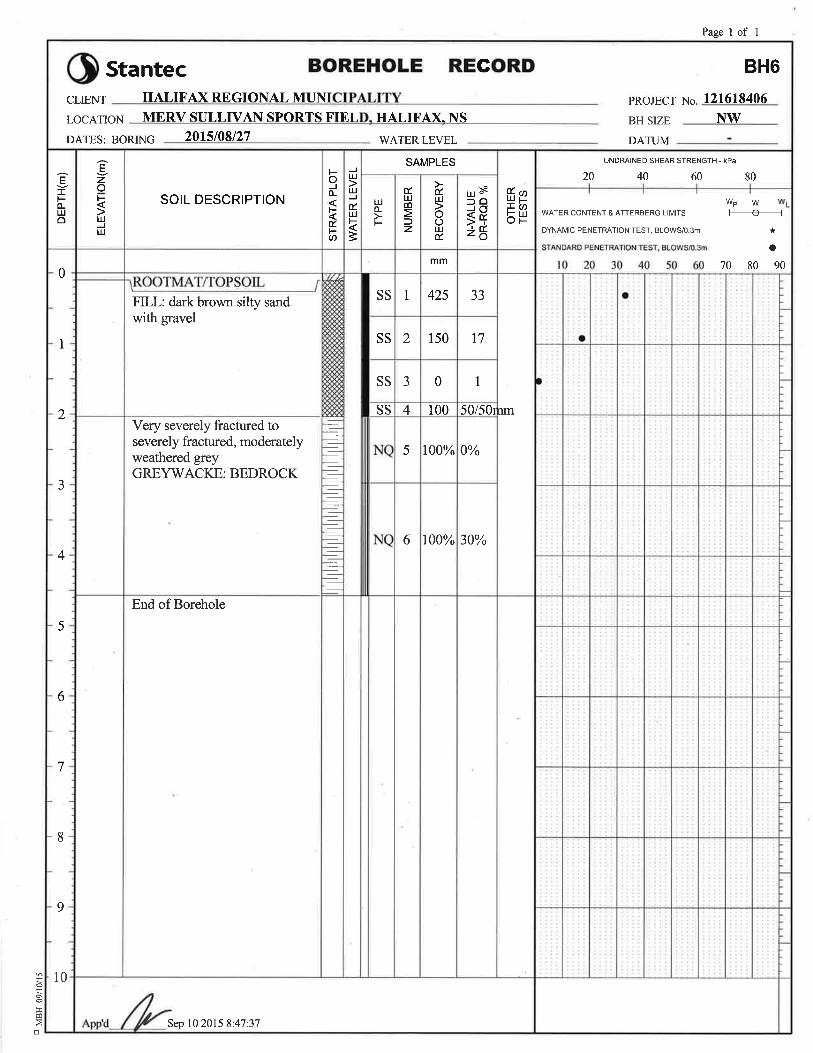
Borehole Records BH1 to BH7
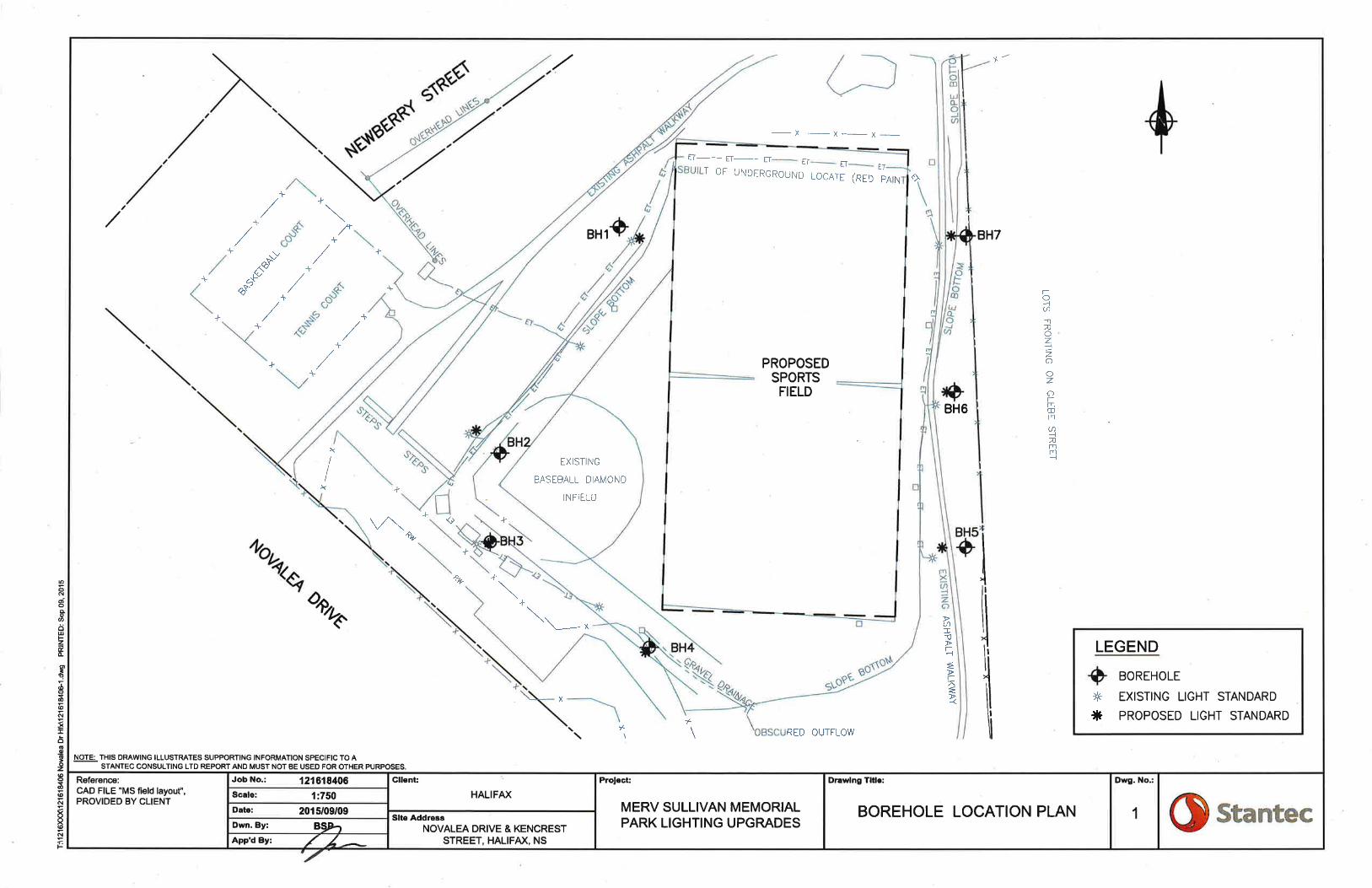
Drawing No. 1, Borehole Location Plan

GEOTECHNICAL INVESTIGATION, PROPOSED LIGHTING UPGRADE, MERV SULLIVAN MEMORIAL
PARK
September 10, 2015
v:\1216\active\121618xxx\121618406\7_reports\geotechnical\rpt_jsm_so_20150910.docx 1
1.0 INTRODUCTION
Stantec Consulting Ltd. (Stantec), acting at the request of HΛLIFΛX has performed a
geotechnical investigation for the proposed lighting upgrade in the Merv Sullivan Memorial Park
in Halifax, Nova Scotia. The purpose of the investigation was to determine soil and bedrock
conditions for use in the design of the proposed foundations.
The scope of this investigation consisted of drilling a borehole at the location of each of the
seven proposed light standards, field and laboratory testing, and the preparation of this
geotechnical report.
This report contains all of our findings from the investigation and has been prepared specifically
and solely for the project described herein.
2.0 SITE DESCRIPTION
The proposed light standards are to be located around the perimeter of the Merv Sullivan
Memorial Park in Halifax, Nova Scotia. The park is bordered by residences and Novalea Drive,
Newberry Street, and Kencrest Avenue. It is understood that this area was a former quarry. There
are currently several underground utilities in the park, including storm water lines and buried
electrical lines.
Our previous experience in the area and geological mapping indicate that the principal native
overburden at the site consists of glacial till comprised of silty sand with gravel overlying
greywacke bedrock of the Goldenville Formation.
3.0 INVESTIGATIVE PROCEDURE
The field component of the geotechnical investigation was carried out on August 26 and 27,
2015. A Stantec geotechnical site representative was on-site to observe the drilling of the
boreholes and to record the subsurface conditions encountered. The location of the boreholes is
shown on the appended Drawing No. 1, Borehole Location Plan.
3.1 BOREHOLES
The boreholes were advanced using a truck mounted CME 55 drill. The depth of the boreholes
ranged between 3.0 and 6.1 metres.
Each borehole was advanced through the overburden using standard 100 millimetre diameter
flight augers and NW sized casing. Soil sampling was carried out at regular intervals using

GEOTECHNICAL INVESTIGATION, PROPOSED LIGHTING UPGRADE, MERV SULLIVAN MEMORIAL
PARK
September 10, 2015
v:\1216\active\121618xxx\121618406\7_reports\geotechnical\rpt_jsm_so_20150910.docx 2
conventional split spoon samplers while performing Standard Penetration Testing. The Standard
Penetration Test (SPT) “N-value” is the number of blows required to advance a 50 mm outside
diameter split spoon sampler a distance of 300 mm into the soil using a standardized drop height
and weight. N values generally provide an indication of relative soil compactness and may also
be used to aid in estimating other soil parameters. Bedrock was cored in all of the boreholes with
NQ sized drill rods.
3.2 SURVEYING
The borehole locations were surveyed by Stantec personnel. The locations were tied into the
proposed light standard locations which were laid out in the field by others.
3.3 LABORATORY TESTING
Soil samples collected during the drilling program were stored in moisture tight containers and
taken to our Dartmouth laboratory for final classification and testing. Soil classification was based
on procedures described in ASTM D2487, Standard Practice for Classification of Soils for
Engineering Purposes (Unified Soil Classification System) and in ASTM D 2488, Standard Practice
for Description and Identification of Soils, Visual Manual Procedure.
Laboratory testing included unconfined compressive strength testing on the bedrock samples
obtained. Results of the laboratory testing are provided on the appended Borehole Records.
4.0 SUBSURFACE CONDITIONS
A detailed description of the subsurface conditions encountered and the sampling conducted
are provided on the appended Borehole Records. An explanation of the terminology and
graphics used in this report are also appended (see the Symbols and Terms Used on Borehole
and Test Pit Records). The conditions encountered in the investigation are summarized in the
following table:
Table 1 Subsurface Conditions
BH
No.
Thickness of Topsoil Layer
(mm)
Thickness of FILL Layer
(m)
Thickness of Glacial TILL Layer
(m)
Depth to Bedrock
(m)
BH1 80 2.2 - 2.3
BH2 - 1.7 - 1.7
BH3 - 1.2 - 1.2
BH4 80 0.4 - 0.5
BH5 50 2.3 - 2.4
BH6 100 1.9 - 2.0
BH7 80 2.5 0.7 3.3

GEOTECHNICAL INVESTIGATION, PROPOSED LIGHTING UPGRADE, MERV SULLIVAN MEMORIAL
PARK
September 10, 2015
v:\1216\active\121618xxx\121618406\7_reports\geotechnical\rpt_jsm_so_20150910.docx 3
4.1 FILL
A layer of fill was encountered in all of the boreholes drilled at this site. The fill was generally
comprised of dark brown silty sand with gravel. The thickness of the fill layer ranged between 0.4
and 2.5 metres. Frequent cobbles and boulders and trace amounts of debris were encountered
in the fill layer.
4.2 GLACIAL TILL
A layer of glacial till was encountered in borehole BH7 beneath the fill layer. The glacial till was
comprised predominately of silty sand with gravel. The thickness of this layer was 0.7 metres.
4.3 BEDROCK
Greywacke bedrock of the Goldenville Formation was encountered in all of the boreholes drilled
at this site. The Rock Quality Designation (RQD) ranged between 0% and 100%, and averaged
36%, indicating that the rock mass quality is predominantly described as severely fractured. The
results of the unconfined compressive strength testing that was completed on samples of the
bedrock are summarized below:
Table 2 Unconfined Compressive Strength Testing Results
BH No. Depth of Sample (m) Unconfined Compressive Strength (MPa)
BH2 2.5-2.6 127
BH4 2.4-2.5 68
4.4 GROUNDWATER
Standpipe was not installed in any of the boreholes drilled for this investigation as the standpipe
may have caused a tripping hazard. It is anticipated that the groundwater surface would be
within close proximity to the ground surface.
It should be noted that groundwater levels are subject to fluctuations by seasonal weather
trends and individual precipitation events, as well as with site use and construction activities.
5.0 RECOMMENDATIONS
5.1 GENERAL
It is understood that the proposed development will consist of the installation of seven new light
standards around the perimeter of the park. It is anticipated that the footings for the light
standards will be constructed on glacial till or bedrock.
GEOTECHNICAL INVESTIGATION, PROPOSED LIGHTING UPGRADE, MERV SULLIVAN MEMORIAL
PARK
September 10, 2015
v:\1216\active\121618xxx\121618406\7_reports\geotechnical\rpt_jsm_so_20150910.docx 4
The scope of this investigation did not include an environmental screening assessment. All fill
should be tested prior to disposal offsite (if necessary).
5.2 SITE PREPARATION
5.2.1 Excavation
It is recommended that all existing rootmat/topsoil and fill encountered be removed from below
the area of the light tower foundations, down to the underlying glacial till or bedrock. Where
bedrock removal is required to achieve design subgrade elevations, removal will require the use
of hydraulic breakers and/or blasting.
Due to the fines content of the native glacial till, it will be sensitive to deterioration from exposure
to construction trafficking, groundwater seepage and surface water runoff. If glacial till bearing
surfaces become softened and disturbed, we recommend over excavation by at least 300 mm
and replacement with granular fill to structural fill requirements stated below.
Temporary de-watering of excavations may be required to control groundwater and surface
water runoff. Surface water should be directed away from excavations and groundwater
seepage should be directed to sumps and disposed of by pumping. Discharge of water must be
completed in accordance with the HRM disposal guidelines.
5.2.2 Structural Fill
If structural fill is required below the foundations, removal of unsuitable materials and
replacement with structural fill should include the footing footprint and extend laterally around
the footing perimeter a distance at least equal to the required thickness of structural fill below
the footing (i.e. 1 horizontal to 1 vertical structural splay).
Granular material such as NSTIR Type 2 Gravel or similar approved non-frost susceptible granular
material is recommended for structural fill below footings (if required).
Structural fill should be compacted to at least 100 percent of Standard Proctor Maximum Dry
Density. The materials should be placed in a lift thickness compatible with the compaction
equipment utilized to ensure that the required degree of compaction is achieved throughout.
5.3 FOUNDATION DESIGN
5.3.1 Spread Footings
Buried spread footings provide both distribution of stress to the founding stratum and resist
overturning of the structure. Often, soil cover over the footing base may provide additional
overturning resistance. The parameters required for design of these types of foundations,
including design bearing resistance pressures, unit weight of compacted granulars (used for

GEOTECHNICAL INVESTIGATION, PROPOSED LIGHTING UPGRADE, MERV SULLIVAN MEMORIAL
PARK
September 10, 2015
v:\1216\active\121618xxx\121618406\7_reports\geotechnical\rpt_jsm_so_20150910.docx 5
backfill), internal angle of friction of soil strata and coefficient of friction for structure to
foundation strata, are provided in Table 3, below.
Table 3 Soil Parameters for Design of Foundations
Parameter Value
Undisturbed Till Intact Bedrock Compacted Granular(1)
Total Unit Weight (kN/m3) 20 26 21
Submerged Unit Weight (kN/m3) 10 16 11
Internal Angle of Friction (degrees) 32 - 36
Concrete/Material Friction Factor (unformed) 0.3 0.65 0.4
Active Earth Pressure Coefficient, Ka 0.31 - 0.25
At Rest Earth Pressure Coefficient Ko 0.47 - 0.41
Passive Earth Pressure Coefficient, Kp 3.25 - 3.85
ULS Bearing Resistance (kPa)(2) 400 1,000 400
SLS Bearing Resistance (kPa)(2) 250 1,000 250
(1) Fill should be placed in lifts appropriately sized for the compaction equipment being used. Backfill should be
compacted to 95 percent of maximum standard Proctor dry density. Structural Fill should be compacted to
100 percent of maximum standard Proctor dry density.
(2) The factored bearing resistance at Ultimate Limit States (ULS) is estimated in accordance with the National Building
Code of Canada (NBCC, 2010). The factored bearing resistance (using a bearing resistance factor of 0.5) at ULS is
provided. SLS bearing resistance provided is estimated assuming a total settlement of 25 mm.
A geotechnical resistance factor of 0.8 should be used in sliding analysis.
In the case of construction over shallow rock, spread footings could be oversized with respect to
bearing requirements to obtain overturning design requirements.
All footings should have an equivalent soil cover of at least 1.2 meters for frost protection.
If passive resistance of backfill is relied upon for design, backfill materials should consist of
imported granular material such as NSTIR Type 2 Gravel or equivalent non-frost susceptible
material. All backfill should be placed in lifts appropriately sized for the compaction equipment
being used and compacted to 95 percent of maximum standard Proctor dry density.
Generally, groundwater levels should be anticipated to rise seasonally and in localized, short
term cases, it should be expected to rise to final graded surfaces around light tower foundations
(i.e. full buoyancy of the foundations should be anticipated).
It is recommended that inspection by experienced geotechnical personnel be carried out
during excavation and backfilling to ensure that all unsuitable soils are removed, that approved
fill materials are used, and that the required compaction is carried out.
GEOTECHNICAL INVESTIGATION, PROPOSED LIGHTING UPGRADE, MERV SULLIVAN MEMORIAL
PARK
September 10, 2015
v:\1216\active\121618xxx\121618406\7_reports\geotechnical\rpt_jsm_so_20150910.docx 6
5.3.2 Rock Anchors
Rock anchors make use of a relatively small footprint to take advantage of the high bearing
strength of bedrock, transferring overturning loads to tension anchors grouted into the bedrock
at depth.
Design of rock anchors should be based on the factored ultimate capacity of the socket, which
is a function of the socket diameter, socket length and average factored bond stress at ULS.
Based on the rock type experience in the region, a factored ultimate bond stress of 300 kPa in
tension; and 400 kPa in compression is recommended for use in preliminary design. This
incorporates a resistance factor of 0.3 for tension, and 0.4 for compression in accordance with
the NBCC, 2010.
The uplift resistance should also consider pulling a cone or wedge of rock and soil as well as the
bond stress. The cone can be taken as a 60° apex from the base of the socket. Where a series of
anchors are anticipated throughout the light tower bases, the uplift will mobilize a zone of rock
which splays outward from the base of the anchors at 30°. A submerged unit weight for bedrock
of 16 kN/m3 should be used for the uplift calculation. Typically a factor of 1.25 is applied to the
submerged weight of rock in this analysis.
Due to the fractured and weathered nature of the bedrock surface, it is recommended that the
upper 1 meter of the bedrock (from the current bedrock surface) be neglected when
determining the rock socket length and socket lengths be kept between 4 m (minimum) and 10
m (maximum). The anchors installations should be monitored full-time by personnel having
experience with anchor installations. The bond length of anchors may need to be increased if it
is found that fractured zone extends beyond 1 meter in depth.
It is recommended that the initial two anchor installations and 2% of the remaining anchor
installations be performance tested, and the remaining installations be proof tested in order to
confirm that the design and the Contractor’s installation methods meet the project
requirements. Further recommendations pertaining to performance and proof testing
procedures can be provided upon request.

GEOTECHNICAL INVESTIGATION, PROPOSED LIGHTING UPGRADE, MERV SULLIVAN MEMORIAL
PARK
September 10, 2015
v:\1216\active\121618xxx\121618406\7_reports\geotechnical\rpt_jsm_so_20150910.docx 7
6.0 CLOSURE
Use of this report is subject to the Statement of General Conditions provided in Appendix A. It is
the responsibility of HΛLIFΛX who is identified as “the Client” within the Statement of General
Conditions, and its agents to review the conditions and to notify Stantec Consulting Ltd. should
any of these be not satisfied. The Statement of General Conditions addresses the following:
Use of the report
Basis of the report
Standard of care
Interpretation of site conditions
Varying or unexpected site conditions
This report was prepared by James Mitchell, P.Eng., PMP and reviewed by Mark Bochmann,
P.Eng. Should you have any questions, please do not hesitate to contact us.
Sincerely,
STANTEC CONSULTING LTD.
James S. Mitchell, P.Eng., PMP Mark Bochmann, P.Eng.
Senior Associate, Geotechnical Engineering Associate, Geotechnical Engineering
GEOTECHNICAL INVESTIGATION, PROPOSED LIGHTING UPGRADE, MERV SULLIVAN MEMORIAL
PARK
September 10, 2015
APPENDIX A Statement of General Conditions
Symbols and Terms Used on Borehole and Test Pit Records
Borehole Records BH1 to BH7
Drawing No. 1, Borehole Location Plan
SEPTEMBER 2013
STATEMENT OF GENERAL CONDITIONS USE OF THIS REPORT: This report has been prepared for the sole benefit of the Client or its agent and may not be used by any third party without the express written consent of Stantec Consulting Ltd. and the Client. Any use which a third party makes of this report is the responsibility of such third party. BASIS OF THE REPORT: The information, opinions, and/or recommendations made in this report are in accordance with Stantec Consulting Ltd.’s present understanding of the site specific project as described by the Client. The applicability of these is restricted to the site conditions encountered at the time of the investigation or study. If the proposed site specific project differs or is modified from what is described in this report or if the site conditions are altered, this report is no longer valid unless Stantec Consulting Ltd. is requested by the Client to review and revise the report to reflect the differing or modified project specifics and/or the altered site conditions. STANDARD OF CARE: Preparation of this report, and all associated work, was carried out in accordance with the normally accepted standard of care in the state or province of execution for the specific professional service provided to the Client. No other warranty is made. INTERPRETATION OF SITE CONDITIONS: Soil, rock, or other material descriptions, and statements regarding their condition, made in this report are based on site conditions encountered by Stantec Consulting Ltd. at the time of the work and at the specific testing and/or sampling locations. Classifications and statements of condition have been made in accordance with normally accepted practices which are judgmental in nature; no specific description should be considered exact, but rather reflective of the anticipated material behavior. Extrapolation of in situ conditions can only be made to some limited extent beyond the sampling or test points. The extent depends on variability of the soil, rock and groundwater conditions as influenced by geological processes, construction activity, and site use. VARYING OR UNEXPECTED CONDITIONS: Should any site or subsurface conditions be encountered that are different from those described in this report or encountered at the test locations, Stantec Consulting Ltd. must be notified immediately to assess if the varying or unexpected conditions are substantial and if reassessments of the report conclusions or recommendations are required. Stantec Consulting Ltd. will not be responsible to any party for damages incurred as a result of failing to notify Stantec Consulting Ltd. that differing site or sub-surface conditions are present upon becoming aware of such conditions. PLANNING, DESIGN, OR CONSTRUCTION: Development or design plans and specifications should be reviewed by Stantec Consulting Ltd., sufficiently ahead of initiating the next project stage (property acquisition, tender, construction, etc), to confirm that this report completely addresses the elaborated project specifics and that the contents of this report have been properly interpreted. Specialty quality assurance services (field observations and testing) during construction are a necessary part of the evaluation of sub-subsurface conditions and site preparation works. Site work relating to the recommendations included in this report should only be carried out in the presence of a qualified geotechnical engineer; Stantec Consulting Ltd. cannot be responsible for site work carried out without being present.

SYMBOLS AND TERMS USED ON BOREHOLE AND TEST PIT RECORDS – JULY 2014 Page 1 of 3
SYMBOLS AND TERMS USED ON BOREHOLE AND TEST PIT RECORDS
SOIL DESCRIPTION
Terminology describing common soil genesis:
Rootmat - vegetation, roots and moss with organic matter and topsoil typically forming a
mattress at the ground surface
Topsoil - mixture of soil and humus capable of supporting vegetative growth
Peat - mixture of visible and invisible fragments of decayed organic matter
Till - unstratified glacial deposit which may range from clay to boulders
Fill - material below the surface identified as placed by humans (excluding buried services)
Terminology describing soil structure:
Desiccated - having visible signs of weathering by oxidization of clay minerals, shrinkage cracks, etc.
Fissured - having cracks, and hence a blocky structure
Varved - composed of regular alternating layers of silt and clay
Stratified - composed of alternating successions of different soil types, e.g. silt and sand
Layer - > 75 mm in thickness
Seam - 2 mm to 75 mm in thickness
Parting - < 2 mm in thickness
Terminology describing soil types:
The classification of soil types are made on the basis of grain size and plasticity in accordance with the Unified
Soil Classification System (USCS) (ASTM D 2487 or D 2488) which excludes particles larger than 75 mm. For
particles larger than 75 mm, and for defining percent clay fraction in hydrometer results, definitions proposed by
Canadian Foundation Engineering Manual, 4th Edition are used. The USCS provides a group symbol (e.g. SM)
and group name (e.g. silty sand) for identification.
Terminology describing cobbles, boulders, and non-matrix materials (organic matter or debris):
Terminology describing materials outside the USCS, (e.g. particles larger than 75 mm, visible organic matter, and
construction debris) is based upon the proportion of these materials present:
Trace, or occasional Less than 10%
Some 10-20%
Frequent > 20%
Terminology describing compactness of cohesionless soils:
The standard terminology to describe cohesionless soils includes compactness (formerly "relative density"), as
determined by the Standard Penetration Test (SPT) N-Value - also known as N-Index. The SPT N-Value is described
further on page 3. A relationship between compactness condition and N-Value is shown in the following table.
Compactness Condition SPT N-Value
Very Loose <4
Loose 4-10
Compact 10-30
Dense 30-50
Very Dense >50
Terminology describing consistency of cohesive soils:
The standard terminology to describe cohesive soils includes the consistency, which is based on undrained shear
strength as measured by in situ vane tests, penetrometer tests, or unconfined compression tests. Consistency
may be crudely estimated from SPT N-Value based on the correlation shown in the following table (Terzaghi and
Peck, 1967). The correlation to SPT N-Value is used with caution as it is only very approximate.
Consistency Undrained Shear Strength Approximate
SPT N-Value kips/sq.ft. kPa
Very Soft <0.25 <12.5 <2
Soft 0.25 - 0.5 12.5 - 25 2-4
Firm 0.5 - 1.0 25 - 50 4-8
Stiff 1.0 - 2.0 50 – 100 8-15
Very Stiff 2.0 - 4.0 100 - 200 15-30
Hard >4.0 >200 >30

SYMBOLS AND TERMS USED ON BOREHOLE AND TEST PIT RECORDS – JULY 2014 Page 2 of 3
ROCK DESCRIPTION
Except where specified below, terminology for describing rock is as defined by the International Society for Rock
Mechanics (ISRM) 2007 publication “The Complete ISRM Suggested Methods for Rock Characterization, Testing
and Monitoring: 1974-2006”
Terminology describing rock quality:
RQD Rock Mass Quality Alternate (Colloquial) Rock Mass Quality
0-25 Very Poor Quality Very Severely Fractured Crushed
25-50 Poor Quality Severely Fractured Shattered or Very Blocky
50-75 Fair Quality Fractured Blocky
75-90 Good Quality Moderately Jointed Sound
90-100 Excellent Quality Intact Very Sound
RQD (Rock Quality Designation) denotes the percentage of intact and sound rock retrieved from a borehole of
any orientation. All pieces of intact and sound rock core equal to or greater than 100 mm (4 in.) long are
summed and divided by the total length of the core run. RQD is determined in accordance with ASTM D6032.
SCR (Solid Core Recovery) denotes the percentage of solid core (cylindrical) retrieved from a borehole of any
orientation. All pieces of solid (cylindrical) core are summed and divided by the total length of the core run (It
excludes all portions of core pieces that are not fully cylindrical as well as crushed or rubble zones).
Fracture Index (FI) is defined as the number of naturally occurring fractures within a given length of core. The
Fracture Index is reported as a simple count of natural occurring fractures.
Terminology describing rock with respect to discontinuity and bedding spacing:
Spacing (mm) Discontinuities Spacing
Bedding
>6000 Extremely Wide -
2000-6000 Very Wide Very Thick
600-2000 Wide Thick
200-600 Moderate Medium
60-200 Close Thin
20-60 Very Close Very Thin
<20 Extremely Close Laminated
<6 - Thinly Laminated
Terminology describing rock strength:
Strength Classification Grade Unconfined Compressive Strength (MPa)
Extremely Weak R0 <1
Very Weak R1 1 – 5
Weak R2 5 – 25
Medium Strong R3 25 – 50
Strong R4 50 – 100
Very Strong R5 100 – 250
Extremely Strong R6 >250
Terminology describing rock weathering:
Term Symbol Description
Fresh W1 No visible signs of rock weathering. Slight discoloration along major
discontinuities
Slightly W2 Discoloration indicates weathering of rock on discontinuity surfaces.
All the rock material may be discolored.
Moderately W3 Less than half the rock is decomposed and/or disintegrated into soil.
Highly W4 More than half the rock is decomposed and/or disintegrated into soil.
Completely W5 All the rock material is decomposed and/or disintegrated into soil.
The original mass structure is still largely intact.
Residual Soil W6 All the rock converted to soil. Structure and fabric destroyed.
SYMBOLS AND TERMS USED ON BOREHOLE AND TEST PIT RECORDS – JULY 2014 Page 3 of 3
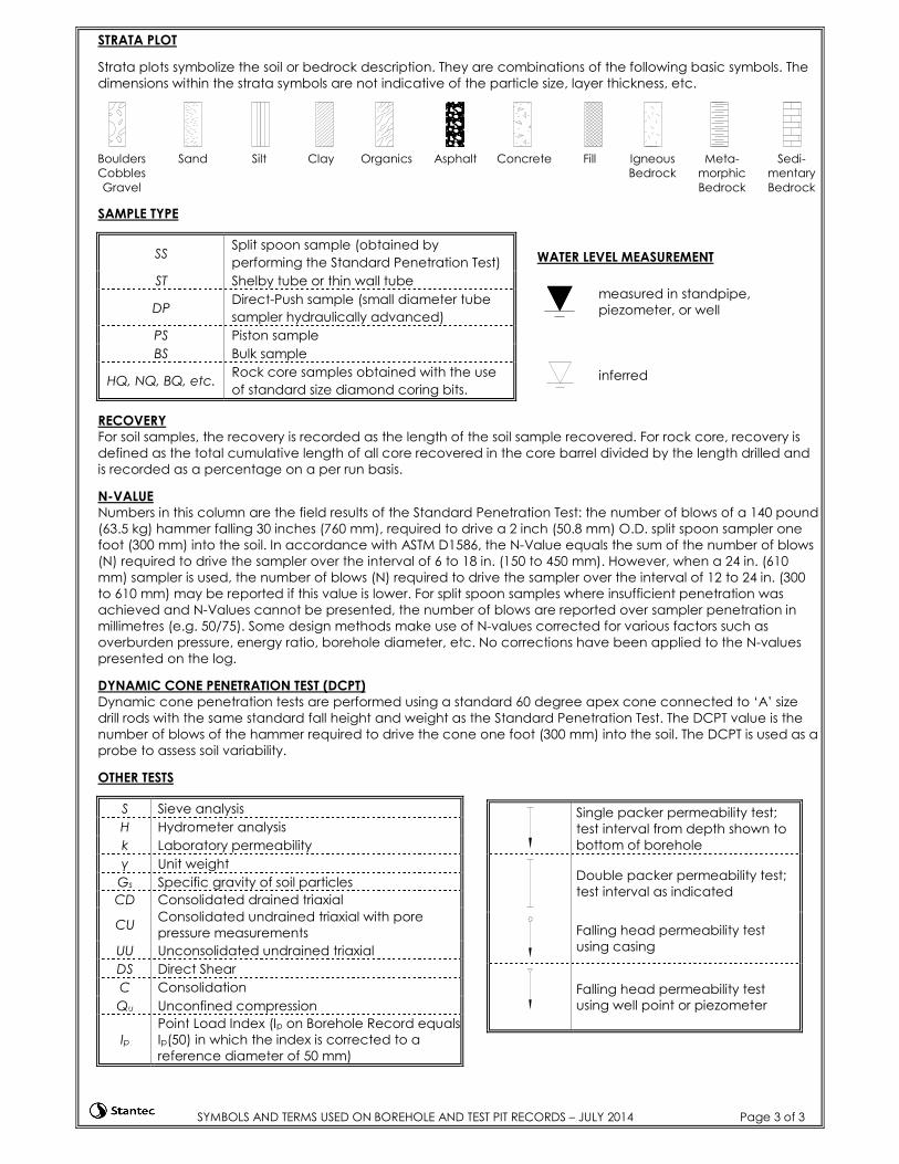
STRATA PLOT
Strata plots symbolize the soil or bedrock description. They are combinations of the following basic symbols. The
dimensions within the strata symbols are not indicative of the particle size, layer thickness, etc.
Boulders
Cobbles
Gravel
Sand Silt Clay Organics Asphalt Concrete Fill Igneous
Bedrock
Meta-
morphic
Bedrock
Sedi-
mentary
Bedrock
SAMPLE TYPE
SS Split spoon sample (obtained by
performing the Standard Penetration Test)
ST Shelby tube or thin wall tube
DP Direct-Push sample (small diameter tube
sampler hydraulically advanced)
PS Piston sample
BS Bulk sample
HQ, NQ, BQ, etc. Rock core samples obtained with the use
of standard size diamond coring bits.
RECOVERY
For soil samples, the recovery is recorded as the length of the soil sample recovered. For rock core, recovery is
defined as the total cumulative length of all core recovered in the core barrel divided by the length drilled and
is recorded as a percentage on a per run basis.
N-VALUE
Numbers in this column are the field results of the Standard Penetration Test: the number of blows of a 140 pound
(63.5 kg) hammer falling 30 inches (760 mm), required to drive a 2 inch (50.8 mm) O.D. split spoon sampler one
foot (300 mm) into the soil. In accordance with ASTM D1586, the N-Value equals the sum of the number of blows
(N) required to drive the sampler over the interval of 6 to 18 in. (150 to 450 mm). However, when a 24 in. (610
mm) sampler is used, the number of blows (N) required to drive the sampler over the interval of 12 to 24 in. (300
to 610 mm) may be reported if this value is lower. For split spoon samples where insufficient penetration was
achieved and N-Values cannot be presented, the number of blows are reported over sampler penetration in
millimetres (e.g. 50/75). Some design methods make use of N-values corrected for various factors such as
overburden pressure, energy ratio, borehole diameter, etc. No corrections have been applied to the N-values
presented on the log.
DYNAMIC CONE PENETRATION TEST (DCPT)
Dynamic cone penetration tests are performed using a standard 60 degree apex cone connected to ‘A’ size
drill rods with the same standard fall height and weight as the Standard Penetration Test. The DCPT value is the
number of blows of the hammer required to drive the cone one foot (300 mm) into the soil. The DCPT is used as a
probe to assess soil variability.
OTHER TESTS
S Sieve analysis
H Hydrometer analysis
k Laboratory permeability
γ Unit weight
Gs Specific gravity of soil particles
CD Consolidated drained triaxial
CU Consolidated undrained triaxial with pore
pressure measurements
UU Unconsolidated undrained triaxial
DS Direct Shear
C Consolidation
Qu Unconfined compression
Ip
Point Load Index (Ip on Borehole Record equals
Ip(50) in which the index is corrected to a
reference diameter of 50 mm)
WATER LEVEL MEASUREMENT
measured in standpipe,
piezometer, or well
inferred
Single packer permeability test;
test interval from depth shown to
bottom of borehole
Double packer permeability test;
test interval as indicated
Falling head permeability test
using casing
Falling head permeability test
using well point or piezometer


Attachment 3
Musco Lighting File 131278C

ILLUMINATION SUMMARY
Not to be reproduced in whole or part without the written consent of MuscoSports Lighting, LLC. ©1981, 2015 Musco Sports Lighting, LLC.
ENGINEERED DESIGNBy: Line Momeni
File # / Date: 131278C 07-Dec-15
2723
2121
2527
3329
2829
3440
3031
3032
3434
2727
2832
3427
3126
2834
3630
2930
2834
3637
2530
3234
3838
2225
3337
3730
2228
3340
3929
2630
3236
3735
3132
3131
3339
3434
2922
2327
F3
F1
F2
37.3m 38.0m
25.9m
68.2m
36.0m
38.0m
36.0m
0.0m
36.9m
27.0m
B2
B1
EXIS
TIN
G B
ASE
LIN
E
SCALE 1 : 1000
0 20m 40m
EQUIPMENT LIST FOR AREAS SHOWNPole Luminaires
QTY LOCATION SIZE GRADEELEVATION
MOUNTINGHEIGHT
LAMPTYPE
QTY /POLE
THISGRID
OTHERGRIDS
1 B1 21.34m - 21.34m 1500W MZ 8 8 01 B2 21.34m - 21.34m 1500W MZ 6 6 02 F1, F3 18.29m - 18.29m 1500W MZ 4 4 01 F2 18.29m - 18.29m 1500W MZ 5 5 05 TOTALS 27 27 0
Pole loca on(s) dimensions are rela veto 0,0 reference point(s)
MY PROJECTName: HRM North End Sports Fields
Loca on: Halifax, NS
GRID SUMMARYName: Soccer/Football
Size: 109.7m x 54.9mSpacing: 9.1m x 9.1m
Height: 0.9m above grade
CONSTANT ILLUMINATIONSUMMARY HORIZONTAL FOOTCANDLES
En re GridGuaranteed Average: 30
Scan Average: 30.79Maximum: 40Minimum: 21Avg / Min: 1.47
Guaranteed Max / Min: 2.5Max / Min: 1.91
UG (adjacent pts): 1.49CU: 0.55
No. of Points: 72LUMINAIRE INFORMATION
Luminaire Type: Green Genera onDesign Usage Hours: 5,000 hours
Design Lumens: 134,000Avg Lamp Tilt Factor: 1.000
No. of Luminaires: 27Avg KW: 42.23 (45.9 max)
Guaranteed Performance: The Guaranteed AverageCONSTANT ILLUMINATION described above is guaranteedfor the design usage hours of the system.Field Measurements: Illumina on measured in accordance withIESNA LM-5-04 and CIBSE LG4. Individual values may vary.See the Warranty document for details.Electrical System Requirements: Refer to AmperageDraw Chart and/or the "Musco Control System Summary"for electrical sizing.Installa on Requirements: Results assume +/- 3%nominal voltage at line side of the ballast and structureslocated within 3 feet (1m) of design loca ons.

ILLUMINATION SUMMARY
Not to be reproduced in whole or part without the written consent of MuscoSports Lighting, LLC. ©1981, 2015 Musco Sports Lighting, LLC.
ENGINEERED DESIGNBy: Line Momeni
File # / Date: 131278C 07-Dec-15
A1
A2
35
39
33
32
26
20
18
19
22
24
39
37
32
34
32
28
25
25
29
29
27
34
32
28
28
30
31
28
30
28
27
29
33
34
28
25
26
27
27
26
26
27
29
28
34
32
27
23
24
24
23
24
26
25
22
30
33
28
24
22
21
20
21
24
19
20
26
30
28
25
21
20
18
19
20
22
28
29
27
26
23
21
18
17
28
31
31
32
28
26
22
17
14
30
34
34
32
28
24
19
21
30
31
29
26
21
19
6.7m
12.2m
9.1m
57.6m
12.2
m
6.7m
61.0
m
7.6m
B2
B1
EXIS
TIN
G B
ASE
LIN
E
SCALE 1 : 1000
0 20m 40m
EQUIPMENT LIST FOR AREAS SHOWNPole Luminaires
QTY LOCATION SIZE GRADEELEVATION
MOUNTINGHEIGHT
LAMPTYPE
QTY /POLE
THISGRID
OTHERGRIDS
2 A1-A2 18.29m - 18.29m 1500W MZ 2 2 01 B1 21.34m - 21.34m 1500W MZ 8 8 01 B2 21.34m - 21.34m 1500W MZ 6 6 04 TOTALS 18 18 0
Pole loca on(s) dimensions are rela veto 0,0 reference point(s)
MY PROJECTName: HRM North End Sports Fields
Loca on: Halifax, NS
GRID SUMMARYName: So ball
Size: 63.4m/65.5m/64.6m - basepath 18.3mSpacing: 6.1m x 6.1m
Height: 0.9m above grade
CONSTANT ILLUMINATIONSUMMARY HORIZONTAL FOOTCANDLES
In eld Ou ieldGuaranteed Average: 30 20
Scan Average: 31.24 25.08Maximum: 39 34Minimum: 23 14Avg / Min: 1.34 1.81
Guaranteed Max / Min: 2 2.5Max / Min: 1.69 2.48
UG (adjacent pts): 1.22 1.60CU: 0.47
No. of Points: 25 82LUMINAIRE INFORMATION
Luminaire Type: Green Genera onDesign Usage Hours: 5,000 hours
Design Lumens: 134,000Avg Lamp Tilt Factor: 1.000
No. of Luminaires: 18Avg KW: 28.15 (30.6 max)
Guaranteed Performance: The Guaranteed AverageCONSTANT ILLUMINATION described above is guaranteedfor the design usage hours of the system.Field Measurements: Illumina on measured in accordance withIESNA LM-5-04 and CIBSE LG4. Individual values may vary.See the Warranty document for details.Electrical System Requirements: Refer to AmperageDraw Chart and/or the "Musco Control System Summary"for electrical sizing.Installa on Requirements: Results assume +/- 3%nominal voltage at line side of the ballast and structureslocated within 3 feet (1m) of design loca ons.

ILLUMINATION SUMMARY
Not to be reproduced in whole or part without the written consent of MuscoSports Lighting, LLC. ©1981, 2015 Musco Sports Lighting, LLC.
ENGINEERED DESIGNBy: Line Momeni
File # / Date: 131278C 07-Dec-15
F3
F1
F2
A1
A2 B2
B1
0.25
0.42
0.65
0.82
1.03
1.07
0.79
0.54
0.46
0.38
0.40
0.54
0.61
0.58
0.55
0.70
1.04
1.11
1.19
1.15
0.84
0.55
0.35
0.34
0.500.76 1.12 1.19 1.17 0.92 0.53 0.37 0.26 0.21
0.18
0.19
0.25
0.36
0.27
0.14
0.10
0.08
0.09
0.09
0.10
0.12
0.12
0.15
0.17
0.18
0.19
0.20
0.19
0.17
0.16
0.15
0.14
0.13
0.140.150.17
0.23
4956
PUB
NOVALEA DRIVE20.574 WIDE
KENCREST AVENUE
18.288 WIDE
NEW
BER
RY
STR
EET
18.2
88 W
IDE
EXIS
TING
BAS
E LI
NE
SCALE 1 : 1500
0 15m 30m
EQUIPMENT LIST FOR AREAS SHOWNPole Luminaires
QTY LOCATION SIZE GRADEELEVATION
MOUNTINGHEIGHT
LAMPTYPE
QTY /POLE
THISGRID
OTHERGRIDS
2 A1-A2 18.29m - 18.29m 1500W MZ 2 2 01 B1 21.34m - 21.34m 1500W MZ 8 8 01 B2 21.34m - 21.34m 1500W MZ 6 6 02 F1, F3 18.29m - 18.29m 1500W MZ 4 4 01 F2 18.29m - 18.29m 1500W MZ 5 5 07 TOTALS 31 31 0
Pole loca on(s) dimensions are rela veto 0,0 reference point(s)
MY PROJECTName: HRM North End Sports Fields
Loca on: Halifax, NS
GRID SUMMARYName: Spill @ 100'
Spacing: 9.1mHeight: 0.9m above grade
CONSTANT ILLUMINATIONSUMMARY HORIZONTAL FOOTCANDLES
En re GridScan Average: 0.4521
Maximum: 1.19Minimum: 0.08
No. of Points: 62LUMINAIRE INFORMATION
Luminaire Type: Green Genera onDesign Usage Hours: 5,000 hours
Design Lumens: 134,000Avg Lamp Tilt Factor: 1.000
No. of Luminaires: 31Avg KW: 48.48 (52.7 max)
Guaranteed Performance: The CONSTANT ILLUMINATIONdescribed above is guaranteed for the designusage hours of the system.Field Measurements: Illumina on measured in accordance withIESNA LM-5-04 and CIBSE LG4. Individual values may vary.See the Warranty document for details.
Electrical System Requirements: Refer to AmperageDraw Chart and/or the "Musco Control System Summary"for electrical sizing.
Installa on Requirements: Results assume +/- 3%nominal voltage at line side of the ballast and structureslocated within 3 feet (1m) of design loca ons.
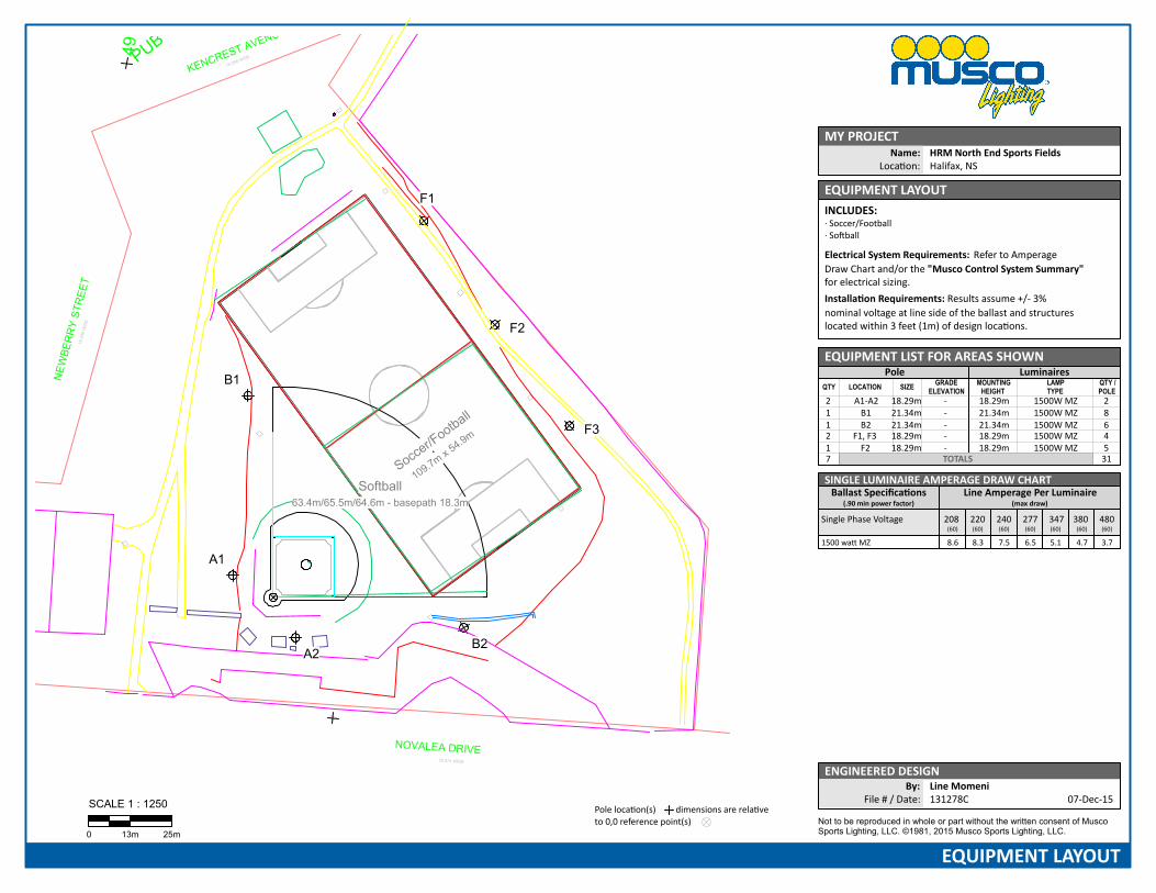
EQUIPMENT LAYOUT
Not to be reproduced in whole or part without the written consent of MuscoSports Lighting, LLC. ©1981, 2015 Musco Sports Lighting, LLC.
ENGINEERED DESIGNBy: Line Momeni
File # / Date: 131278C 07-Dec-15
Soccer/F
ootball
109.7m x 54.9m F3
F1
F2
Softball63.4m/65.5m/64.6m - basepath 18.3m
A1
A2B2
B1
4956
PUB
NOVALEA DRIVE20.574 WIDE
KENCREST AVENUE
18.288 WIDEN
EWBE
RR
Y ST
REE
T18
.288
WID
E
EX
ISTI
NG
BA
SE
LIN
E
SCALE 1 : 1250
0 13m 25m
Pole loca on(s) dimensions are rela veto 0,0 reference point(s)
MY PROJECTName: HRM North End Sports Fields
Loca on: Halifax, NS
EQUIPMENT LAYOUTINCLUDES:· Soccer/Football· So ball
Electrical System Requirements: Refer to AmperageDraw Chart and/or the "Musco Control System Summary"for electrical sizing.Installa on Requirements: Results assume +/- 3%nominal voltage at line side of the ballast and structureslocated within 3 feet (1m) of design loca ons.
EQUIPMENT LIST FOR AREAS SHOWNPole Luminaires
QTY LOCATION SIZE GRADEELEVATION
MOUNTINGHEIGHT
LAMPTYPE
QTY /POLE
2 A1-A2 18.29m - 18.29m 1500W MZ 21 B1 21.34m - 21.34m 1500W MZ 81 B2 21.34m - 21.34m 1500W MZ 62 F1, F3 18.29m - 18.29m 1500W MZ 41 F2 18.29m - 18.29m 1500W MZ 57 TOTALS 31
SINGLE LUMINAIRE AMPERAGE DRAW CHARTBallast Speci ca ons
(.90 min power factor)Line Amperage Per Luminaire
(max draw)
Single Phase Voltage 208(60)
220(60)
240(60)
277(60)
347(60)
380(60)
480(60)
1500 wa MZ 8.6 8.3 7.5 6.5 5.1 4.7 3.7

Attachment 4
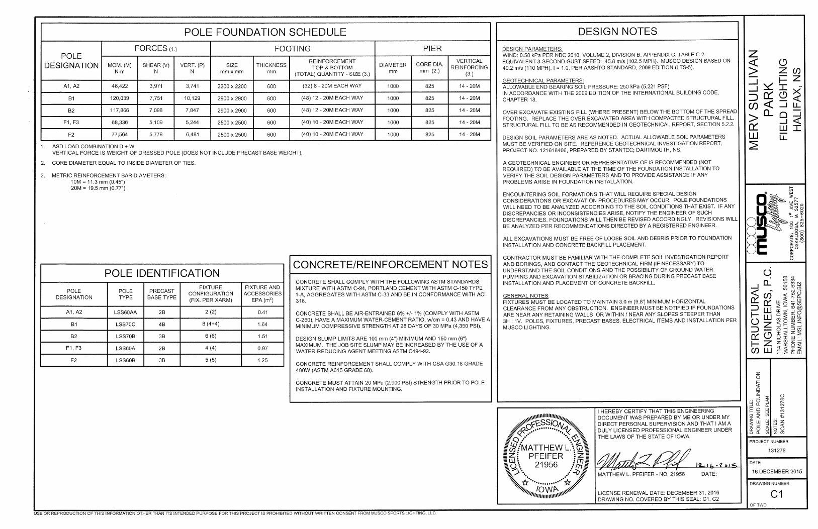
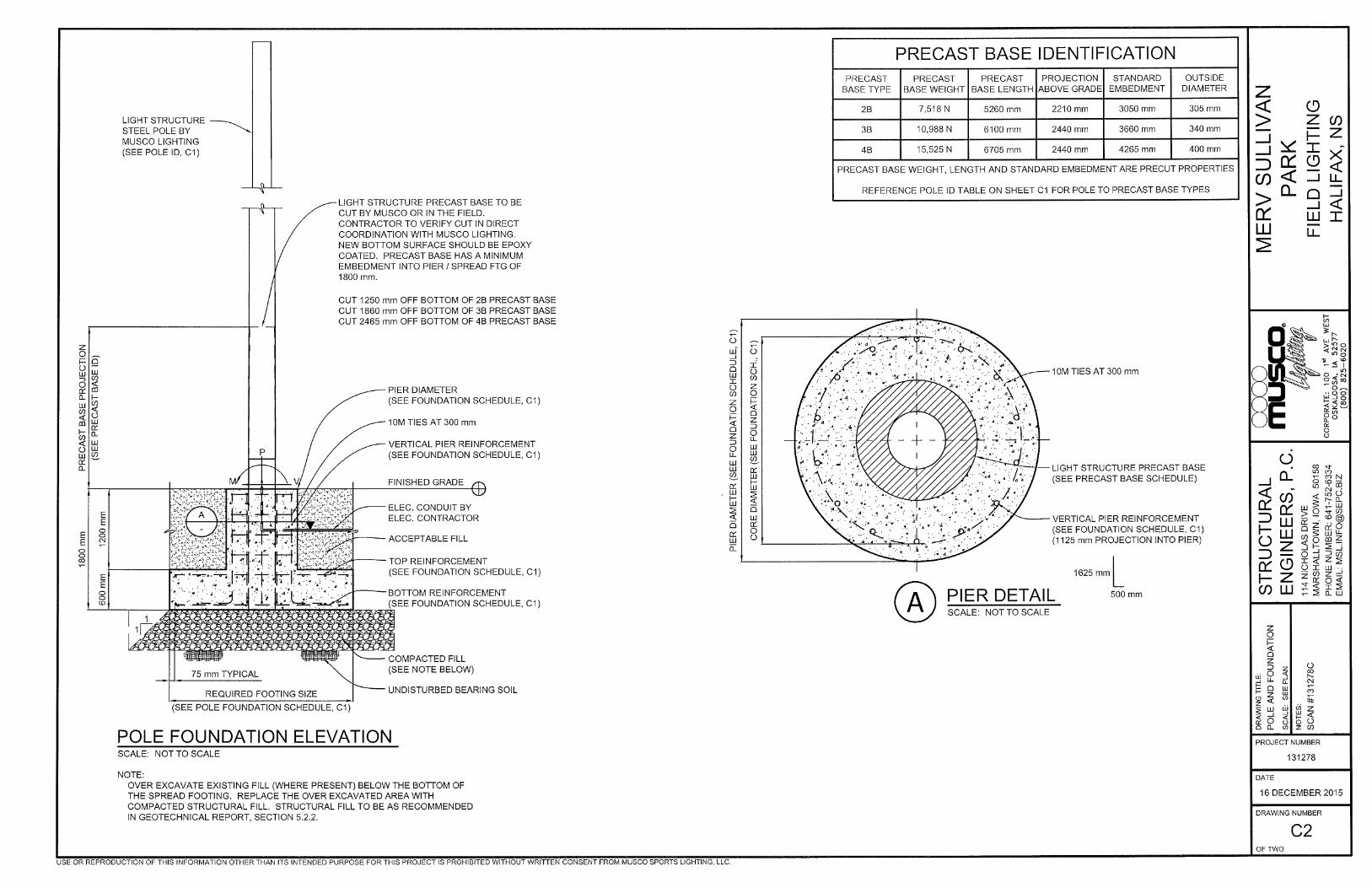
Musco Lighting Drawings 131278-C1 and 131278-C2