addendum # 1 - rhode · pdf fileaddendum # 1. 12/7/16 . solicitation #7551144 . ... m-101...
TRANSCRIPT

State of Rhode Island
Department of Administration / Division of Purchases One Capitol Hill, Providence, Rhode Island 02908-5855
Tel: (401) 574-8100 Fax: (401) 574-8387
ADDENDUM # 1
12/7/16
Solicitation #7551144
Title: Replacement of Existing Cooling Tower – CCRI Newport Campus
Submission Deadline: December 19, 2016 @ 2:00 pm (ET)
Per the issuance of ADDENDUM #1 the following are noted:
Addendum 1 (See Attached) Questions and Responses Related Documents Pre-Bid Attendance Sheet
Interested Parties should monitor this website on a regular basis, for any additional information that may be posted. Gary P. Mosca Chief Buyer

Addendum No. 112/06/2016
7551144 Cooling Tower Replacement – CCRI Newport Campus
1. Question 1: The bid form asks for an Alternate No. 1 that isn’t described in the specs nor shown onthe drawings and Sect. 011000 Summary of Work states par. 1.2, page 2 that there are no alternates;please clarify.
F&O Response: Refer to Specification section 23 65 00, par. 1.3A “Substitutions” for requirements.
2. Question 2: Will a water treatment system and/or chemicals be required or is there an existingsystem that will remain? Will a glycol solution be required?
F&O Response: There is an existing chemical water treatment system that shall remain and isconnected to existing to remain piping. A glycol solution is not required.
3. Question 3: Per Sect. 236500, par. 2.1A, page 3, it appears that Delta Cooling Towers is theproprietary cooling tower vendor, are we correct?
F&O Response: The Delta cooling tower was used as the basis of design to meet CCRI’s projectrequirements for a non-corroding tower that fits in the available space with the necessary clearances.Specification section 23 65 00, par. 1.3A “Substitutions”, describes how the Contractor may proposeand submit substitutions for review.
4. Question 4: Drawings MD-101, M-101 & M-501 are confusing on piping removal & new pipeinstallation. Is it safe to say that this work begins at the outside face of the wall?
F&O Response: Use drawing M-101 to identify the beginning of new piping scope of work. Adjustdemolition of existing piping shown on MD-101, and the new piping shown on M-501, to thelocations shown on M-101. Note that on drawings MD-101, M-101, and M-501, new piping has adarker thicker lineweight than existing piping.
5. Question 5: Vibration isolator mounts are shown on detail 2/S-101 & mentioned in the coolingtower installation Sect. 236500, par. 3.2B, page 7, but there is no Section 230548 as mentioned andthey are not specified to be furnished with the cooling tower. Please verify that they are required andif so, provide quantities and model numbers. Will seismic calculations have to be provided?
F&O Response: Yes, vibration isolation for the cooling tower shall be required. Yes, seismiccalculations that define the need and type of restraint shall be provided by the seismic restraintequipment supplier. See also the attached specification section 23 05 48.
6. Question 6: We did not look at the ductwork insulation during the pre-bid walk-thru this morningthat has to be removed & replaced as shown on M-102. Provide contact information at the campusto make arrangements to look at this.
F&O Response: Mark Libutti 401-825-2380

7. Question 7: Will ductwork insulation mockups be required per Sect. 230713, par. 1.4C, pages 1-2?
F&O Response: Yes, an insulation mockup shall be required for review by the Engineer and Ownerbefore the reinsulation part of the project begins.
8. Question 8: Five (5) year warranty by the contractor on the entire tower per Sect. 236500, par. 1.8B,page 3, far exceeds the normal one (1) year warranty after acceptance and is not covered by themanufacturer’s warranty, we request that this is reduced to one (1) year by the contractor.
F&O Response: THE COLLEGE REQUIRES AN EXTENDED WARRANTEE BEPROVIDED.
9. Question 9: The drawing shows we (REYMSA) can meet the footprint of the Delta Tower.
F&O Response: Please refer to response to Question 3.
10. Question 10: I represent REYMSA Seamless Fiberglass Cooling Towers who is competitive withDelta Cooling Towers, but REYMSA is a better construction and performs better than Delta.You or the Architect can have the REYMSA Tower painted any color you want.We have REYMSA Towers at National Grid in RI and Mass Bay CC in MA.I have also attached a brochure for your review.
F&O Response: Please refer to response to Question 3.

FUSS & O’NEILL COOLING TOWER REPLACEMENT20151126.A10 COMMUNITY COLLEGE OF RI (CCRI)
VIBRATION AND SEISMIC RESTRAINT FOR HVAC EQUIPMENT 230713 - 1\\private\dfs\Projectdata\P2015\1126\A10\Deliverables\Bid&ConstructionDocuments\CD\Specifications\230548_VIB_SEISMIC.DOC
PART 1 - GENERAL
1.1 RELATED DOCUMENTS
A. Drawings and general provisions of the Contract, including General and Supplementary Conditionsand Division 01 Specification Sections, apply to this Section.
1.2 SCOPE OF WORK
A. All new and disturbed fuel piping (natural gas, propane, fuel oil) shall have seismic restraints.
B. Cooling tower shall receive seismically restrained spring vibration isolators with a 1” minimumdeflection. Provide the number, type, size, and distribution of spring isolators as required by thecooling tower manufacturer.
1.3 DESCRIPTION
A. Intent
1. All mechanical equipment, piping and ductwork as noted on the equipment schedule or inthis Specification shall be mounted on vibration isolators to prevent the transmission ofvibration and mechanically transmitted sound to the building structure. Vibration isolatorsshall be selected in accordance with the weight distribution so as to produce reasonablyuniform deflections.
2. All isolators and isolation materials shall be of the same manufacturer and shall be certifiedby the manufacturer.
3. It is the intent of the seismic portion of this Specification to keep all mechanical buildingsystem components in place during a seismic event.
4. All such systems must be installed in strict accordance with seismic codes, componentmanufacturer and building construction standards. Whenever a conflict occurs between themanufacturer or construction standards, the most stringent shall apply.
5. This Specification is considered to be minimum requirements for seismic consideration andis not intended as a substitute for legislated, more stringent, national, state or localconstruction requirements (such as California Title 24, California OSHPD, CanadianBuilding Codes, or other requirements).
6. Any variance or non-compliance with these Specification requirements shall be corrected bythe Contractor in an approved manner.
7. Seismic restraints shall be designed in accordance with seismic force levels as detailed in thestate’s commercial Building Code and the American Society of Civil Engineer’s Standard for“Minimum Design Loads for Buildings and Other Structures (ASCE/SEI 7)” also known asASCE 7.
B. The work in this section includes, but is not limited to the following:

FUSS & O’NEILL COOLING TOWER REPLACEMENT20151126.A10 COMMUNITY COLLEGE OF RI (CCRI)
VIBRATION AND SEISMIC RESTRAINT FOR HVAC EQUIPMENT 230713 - 2\\private\dfs\Projectdata\P2015\1126\A10\Deliverables\Bid&ConstructionDocuments\CD\Specifications\230548_VIB_SEISMIC.DOC
1. Vibration isolation for piping, ductwork and equipment.2. Equipment isolation bases.3. Flexible piping connections.4. Seismic restraints for isolated equipment.5. Seismic restraints for non-isolated equipment.6. Certification of seismic restraint designs and installation supervision.7. Certification of seismic attachment of housekeeping pads.8. All mechanical systems. Equipment buried underground is excluded but entry of services
through the foundation wall is included. Equipment referred to below is typical. (Equipmentnot listed is still included in this Specification)
AC Units Comp Room Units PumpsAir Distribution Boxes Condensers Rooftop UnitsAir Handling Units Condensing Units Tanks (All types)Air Separators Cooling Towers Unit HeatersBoilers Ductwork Variable Frequency DrivesCabinet Heaters Fans Water HeatersChillers Heat ExchangersCompressors Piping
C. Definitions
1. Life Safety Systems: All systems involved with fire protection including sprinkler piping, firepumps, jockey pumps, fire pump control panels, service water supply piping, water tanks,fire dampers and smoke exhaust systems.
a. All medical and life support systems.b. Fresh air relief systems on emergency control sequence including air handlers,
conduit, duct, dampers, etc.
2. Positive Attachment: A cast-in anchor, a drill-in wedge anchor, a double sided beam clamploaded perpendicular to a beam, or a welded or bolted connection to structure. Single sided"C" type beam clamps for support rods of overhead piping, ductwork, fire protection, or anyother equipment are not acceptable on this Project as seismic anchor points.
3. Transverse Bracing: Restraint(s) applied to limit motion perpendicular to the centerline ofthe pipe or duct.
4. Longitudinal Bracing: Restraint(s) applied to limit motion parallel to the centerline of thepipe, or duct.
1.4 SUBMITTAL
A. The manufacturer of vibration isolation and seismic restraints shall provide submittals for productsas follows:

FUSS & O’NEILL COOLING TOWER REPLACEMENT20151126.A10 COMMUNITY COLLEGE OF RI (CCRI)
VIBRATION AND SEISMIC RESTRAINT FOR HVAC EQUIPMENT 230713 - 3\\private\dfs\Projectdata\P2015\1126\A10\Deliverables\Bid&ConstructionDocuments\CD\Specifications\230548_VIB_SEISMIC.DOC
1. Include rated load, rated deflection, and overload capacity for each vibration isolation device.
2. Descriptive Data:
a. Catalog cuts or data sheets on vibration isolators and specific restraints detailingcompliance with the Specification.
b. Detailed schedules of flexible and rigidly mounted equipment, showing vibrationisolators and seismic restraints by referencing numbered descriptive Drawings.
3. Shop Drawings:
a. Submit fabrication details for equipment bases including dimensions, structuralmember sizes and support point locations.
b. Provide all details of suspension and support for ceiling hung equipment.c. Where walls, floors, slabs or supplementary steel work are used for seismic restraint
locations, details of acceptable attachment methods for ducts, and pipe must beincluded and approved before the condition is accepted for installation. Restraintmanufacturers' submittals must include spacing, static loads and seismic loads at allattachment and support points.
d. Provide specific details of seismic restraints and anchors; include number, size andlocations for each piece of equipment.
e. Submittals for all directional seismic snubbers shall include the load deflection curvesup to 1/2" deflection in the x, y and z planes.
4. Delegated-Design Submittal: For each vibration isolation and seismic-restraint device.
a. Include design calculations and details for selecting vibration isolators, seismicrestraints, and vibration isolation bases complying with performance requirements,design criteria, and analysis data signed and sealed by the qualified professionalengineer responsible for their preparation.
b. Design Calculations: Calculate static and dynamic loading due to equipment weight,operation, and seismic and wind forces required to select vibration isolators andseismic and wind restraints and for designing vibration isolation bases.
1) Coordinate design calculations with wind load calculations required for equipmentmounted outdoors. Comply with requirements in other Sections for equipmentmounted outdoors.
5. Seismic Certification and Analysis:
a. Seismic restraint calculations must be provided for all connections of equipment tothe structure. Calculations must be stamped by a registered professional engineer withat least five years of seismic design experience, licensed in the state of the joblocation.
b. All restraining devices shall have a preapproval number from California OSHPD orsome other recognized government agency showing maximum restraint ratings.Preapprovals based on independent testing are preferred to preapprovals based oncalculations. Where preapproved devices are not available, submittals based on

FUSS & O’NEILL COOLING TOWER REPLACEMENT20151126.A10 COMMUNITY COLLEGE OF RI (CCRI)
VIBRATION AND SEISMIC RESTRAINT FOR HVAC EQUIPMENT 230713 - 4\\private\dfs\Projectdata\P2015\1126\A10\Deliverables\Bid&ConstructionDocuments\CD\Specifications\230548_VIB_SEISMIC.DOC
independent testing are preferred. Calculations (including the combining of tensileand shear loadings) to support seismic restraint designs must be stamped by aregistered professional engineer with at least five years of seismic design experienceand licensed in the state of the job location. Testing and calculations must includeboth shear and tensile loads, as well as, one test or analysis at 45 degrees to theweakest mode.
c. Analysis must indicate calculated dead loads, static seismic loads and capacity ofmaterials utilized for connections to equipment and structure. Analysis must detailanchoring methods, bolt diameter, embedment and/or welded length. All seismicrestraint devices shall be designed to accept, without failure, the forces detailed in thestate’s commercial Building Code and ASCE 7 acting through the equipment centerof gravity. Overturning moments may exceed forces at ground level.
1.5 PERFORMANCE REQUIREMENTS
A. Delegated Design: Design trapeze pipe hangers and equipment supports, including comprehensiveengineering analysis by a qualified professional engineer, using performance requirements anddesign criteria indicated.
B. Structural Performance: Hangers and supports for HVAC piping and equipment shall withstandthe effects of gravity loads and stresses within limits and under conditions indicated according toASCE/SEI 7.
C. Design supports for multiple pipes, including pipe stands, capable of supporting combined weightof supported systems, system contents, and test water.
D. Design equipment supports capable of supporting combined operating weight of supportedequipment and connected systems and components.
E. Design seismic-restraint hangers and supports for piping and equipment..
1.6 CODE AND STANDARDS REQUIREMENTS
A. Typical Applicable codes and Standards
1. International Building Code (IBC)2. ASCE/SEI 73. State Building Code with ammendments and modifications
1.7 MANUFACTURER'S RESPONSIBILITY
A. Manufacturer of vibration isolation and seismic control equipment shall have the followingresponsibilities:
1. Determine vibration isolation and seismic restraint sizes and locations.2. Provide vibration isolation and seismic restraints as scheduled or specified.

FUSS & O’NEILL COOLING TOWER REPLACEMENT20151126.A10 COMMUNITY COLLEGE OF RI (CCRI)
VIBRATION AND SEISMIC RESTRAINT FOR HVAC EQUIPMENT 230713 - 5\\private\dfs\Projectdata\P2015\1126\A10\Deliverables\Bid&ConstructionDocuments\CD\Specifications\230548_VIB_SEISMIC.DOC
3. Provide calculations and materials if required for restraint of unisolated equipment.4. Provide installation instructions, Drawings and trained field supervision to insure proper
installation and performance.5. Provide field survey of the installation and submit letter to Engineer stating that the seismic
and vibration isolation equipment has been installed in accordance with the manufacturer'sinstructions.
1.8 RELATED WORK
A. Housekeeping Pads
1. Housekeeping pad reinforcement and monolithic pad attachment to the structure details anddesign shall be prepared by the restraint vendor if not already indicated on the Drawings.
2. Housekeeping pads shall be coordinated with restraint vendor and sized to provide aminimum edge distance of ten (10) bolt diameters all around the outermost anchor bolt toallow development of full drill-in wedge anchor ratings. If cast-in anchors are to be used, thehousekeeping pads shall be sized to accommodate the ACI requirements for bolt coverageand embedment.
B. Supplementary Support Steel
1. Contractor shall supply supplementary support steel for all equipment, piping, ductwork, etc.including roof mounted equipment, as required or specified.
C. Attachments
1. Contractor shall supply restraint attachment plates cast into housekeeping pads, concreteinserts, double sided beam clamps, etc., in accordance with the requirements of the vibrationvendor's calculations.
1.9 SEISMIC FORCE LEVELS
A. Seismic analysis shall be in accordance with the state’s building code and the latest version ofInternational Building Code, whichever is more conservative.
PART 2 - PRODUCTS
2.1 INTENT
A. All vibration isolators and seismic restraints described in this Section shall be the product of asingle manufacturer. Mason Industry's products are the basis of these Specifications; products ofother manufacturers are acceptable provided their systems strictly comply with the Specificationand have the approval of the Engineer. Submittals and certification sheets shall be in accordancewith Part 1.4 of this Specification.

FUSS & O’NEILL COOLING TOWER REPLACEMENT20151126.A10 COMMUNITY COLLEGE OF RI (CCRI)
VIBRATION AND SEISMIC RESTRAINT FOR HVAC EQUIPMENT 230713 - 6\\private\dfs\Projectdata\P2015\1126\A10\Deliverables\Bid&ConstructionDocuments\CD\Specifications\230548_VIB_SEISMIC.DOC
B. For the purposes of this Project, failure is defined as the discontinuance of any attachment pointbetween equipment or structure, vertical permanent deformation greater than 1/8 inch and/orhorizontal permanent deformation greater than 1/4 inch.
2.2 PRODUCT DESCRIPTIONS
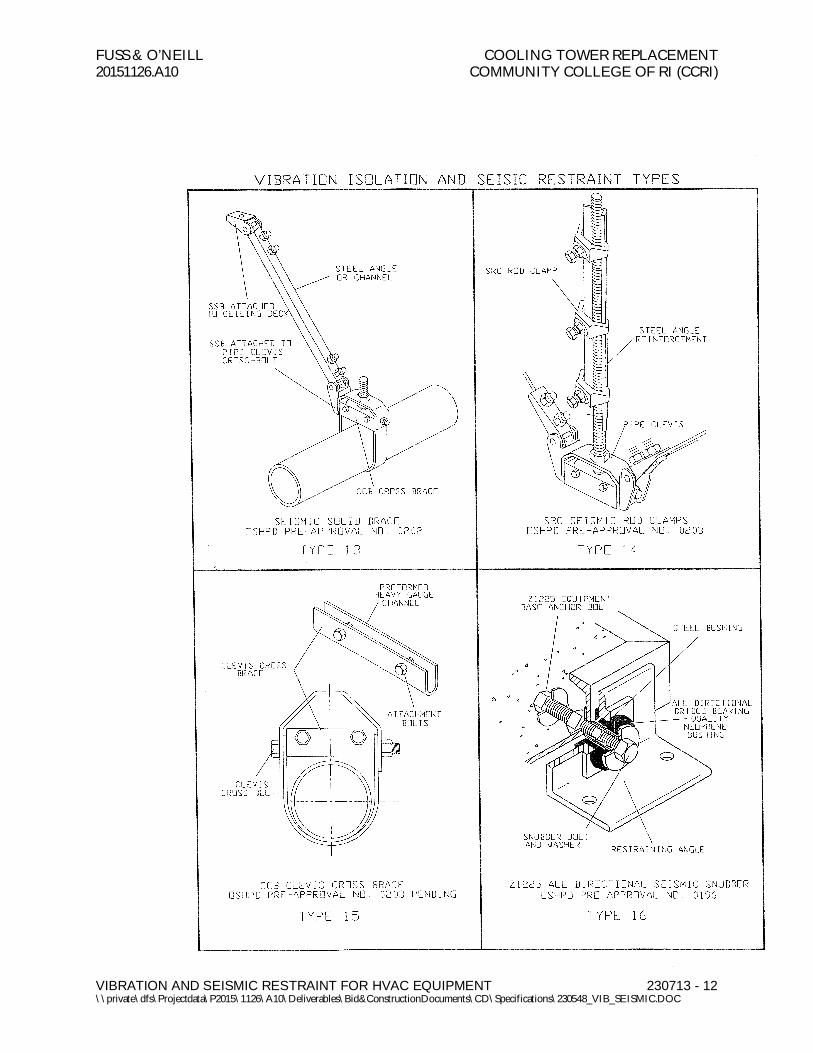
A. Vibration Isolator and Seismic Restraint TypesThe numbers of the following paragraphs correlate to the graphic representations at the end of this Article.
1. Two layers of 3/4-inch thick neoprene pad consisting of 2-inch square waffle modulesseparated horizontally by a 16 gage galvanized shim. Load distribution plates shall be used asrequired. Pads shall be Type Super "W" as manufactured by Mason Industries, Inc.
2. Not Used3. Sheet metal panels shall be bolted to the walls or supporting structure by assemblies
consisting of a neoprene bushing cushioned between 2 steel sleeves. The outer sleeveprevents the sheet metal from cutting into the neoprene. Enlarge panel holes as required.Neoprene elements pass over the bushing to cushion the back panel horizontally. A steeldisc covers the inside neoprene element and the inner steel sleeve is elongated to act as astop so tightening the anchor bolts does not interfere with panel isolation in 3 planes.Bushing assemblies can be applied to the ends of steel cross members where applicable. Allneoprene shall be bridge-bearing quality. Bushing assemblies shall be type PB asmanufactured by Mason Industries, Inc.
4. A one piece molded bridge bearing neoprene washer/bushing. The bushing shall surroundthe anchor bolt and have a flat washer face to avoid metal-to-metal contact. Neoprenebushings shall be type HG as manufactured by Mason Industries, Inc.
5. Not Used6. SLR Type Restrained Spring Mount7. SSLFH Type Housed Spring Mount8. Not Used9. Not Used10. Hangers shall consist of rigid steel frames containing minimum 1-¼ inch thick neoprene
elements at the top and a steel spring with general characteristics as in Type 5 seated in asteel washer reinforced neoprene cup on the bottom. The neoprene element and the cupshall have neoprene bushings projecting through the steel box. To maintain stability theboxes shall not be articulated as clevis hangers nor the neoprene element stacked on top ofthe spring. Spring diameters and hanger box lower hole sizes shall be large enough to permitthe hanger rod to swing through a 30 degree arc from side to side before contacting the rodbushing and short circuiting the spring. Submittals shall include a hanger Drawing showingthe 30 degree capability. Hangers shall be type 30N as manufactured by Mason Industries,Inc.
11. Precompressed hangers shall be as specified in Paragraph 2.3 A.10., but they shall also belocked at the rated deflection by means of a resilient seismic upstop to keep the piping orequipment at a fixed elevation during installation. The hangers shall be designed with arelease mechanism to free the spring after the installation is complete and the hanger issubjected to its full load. Deflection shall be clearly indicated by means of a scale. Submittalsshall include a Drawing of the hanger showing the 30 degree capability. Hangers shall betype PC30N as manufactured by Mason Industries, Inc.

FUSS & O’NEILL COOLING TOWER REPLACEMENT20151126.A10 COMMUNITY COLLEGE OF RI (CCRI)
VIBRATION AND SEISMIC RESTRAINT FOR HVAC EQUIPMENT 230713 - 7\\private\dfs\Projectdata\P2015\1126\A10\Deliverables\Bid&ConstructionDocuments\CD\Specifications\230548_VIB_SEISMIC.DOC
Types 12 - 14 apply to trapeze as well as clevis hanger locations. At trapeze anchor locationspiping must be shackled to the trapeze. Types apply to hanging equipment as well.
12. Seismic Cable Restraints shall consist of galvanized steel aircraft cables sized to resist seismicloads with a minimum safety factor of 2 and arranged to provide all-directional restraint.Cable end connections shall be steel assemblies that swivel to final installation angle andutilize two clamping bolts to provide proper cable engagement. Cables must not be allowedto bend across sharp edges. Cable assemblies shall have an anchorage preapproval "R"number from OSHPD in the state of California verifying the maximum certified loadratings. Cable assemblies shall be Type SCB at the ceiling and at the clevis bolt, SCBHbetween the hanger rod nut and the clevis, or SCBV if clamped to a beam all asmanufactured by Mason Industries, Inc.
13. Seismic solid braces shall consist of steel angles or channels to resist seismic loads with aminimum safety factor of 2 and arranged to provide all directional restraint. Seismic solidbrace end connectors shall be steel assemblies that swivel to the final installation angle andutilize two through bolts to provide proper attachment. Seismic solid brace assembly shallhave anchorage preapproval "R" number from OSHPD in the state of California verifyingthe maximum certified load ratings. Solid seismic brace assemblies shall be type SSB asmanufactured by Mason Industries, Inc.
14. Steel angles, sized to prevent buckling, shall be clamped to pipe or equipment rods utilizing aminimum of three ductile iron clamps at each restraint location when required. Welding ofsupport rods is not acceptable. Rod clamp assemblies shall have an anchorage preapproval"R" number from OSHPD in the state of California. Rod clamp assemblies shall be TypeSRC as manufactured by Mason Industries, Inc.
15. Pipe clevis cross bolt braces are required in all restraint locations. They shall be specialpurpose preformed channels deep enough to be held in place by bolts passing over the crossbolt. Clevis cross braces shall have an anchorage preapproval "R" number from OSHPD inthe State of California. Clevis cross brace shall be type CCB as manufactured by MasonIndustries, Inc.
16. All-directional seismic snubbers shall consist of interlocking steel members restrained by aone-piece molded neoprene bushing of bridge bearing neoprene. Bushing shall bereplaceable and a minimum of 1/4 inch thick. Rated loadings shall not exceed 1000 psi. Aminimum air gap of 1/8 inch shall be incorporated in the snubber design in all directionsbefore contact is made between the rigid and resilient surfaces. Snubber end caps shall beremovable to allow inspection of internal clearances. Neoprene bushings shall be rotated toinsure no short circuits exist before systems are activated. Snubbers shall have an anchoragepreapproval "R" number from OSHPD in the State of California verifying the maximumcertified horizontal and vertical load ratings. Snubber shall be Type Z-1225 as manufacturedby Mason Industries, Inc.
17. Not Used18. Stud wedge anchors shall be manufactured from full diameter wire, not from undersized
wire that is "rolled up" to create the thread. The stud anchor shall also have a safety shoulderwhich fully supports the wedge ring under load. The stud anchors shall have an evaluationreport number from the I.C.B.O Evaluation Service, Inc. verifying its allowable loads. Drill-in stud wedge anchors shall be type SAS as manufactured by Mason Industries, Inc.
19. Female wedge anchors are preferred in floor locations so isolators or equipment can be slidinto place after the anchors are installed. Anchors shall be manufactured from full diameter

FUSS & O’NEILL COOLING TOWER REPLACEMENT20151126.A10 COMMUNITY COLLEGE OF RI (CCRI)
VIBRATION AND SEISMIC RESTRAINT FOR HVAC EQUIPMENT 230713 - 8\\private\dfs\Projectdata\P2015\1126\A10\Deliverables\Bid&ConstructionDocuments\CD\Specifications\230548_VIB_SEISMIC.DOC
wire, and shall have a safety shoulder to fully support the wedge ring under load. Femalewedge anchors shall have an evaluation report number from the I.C.B.O Evaluation Service,Inc. verifying to its allowable loads. Drill-in female wedge anchors shall be type SAB asmanufactured by Mason Industries, Inc.
20. Not Used21. Not Used22. Not Used23. Not Used24. Flexible stainless steel hose shall have stainless steel braid and carbon steel fittings. Sizes
3 inches and larger shall be flanged. Smaller sizes shall have male nipples. Minimum lengthsshall be as tabulated:
a. Flanged Male Nipples3 x 14 10 x 26 1/2 x 9 1-1/2 x 134 x 15 12 x 28 3/4 x 10 2 x 145 x 19 14 x 30 1 x 11 2-1/2 x 186 x 20 16 x 32 1-1/4 x 12 8 x 22
b. Hoses shall be installed on the equipment side of the shut-off valves horizontally andparallel to the equipment shafts wherever possible. Hoses shall be type BSS asmanufactured by Mason Industries, Inc.
25. Not Used26. Not Used27. Not Used28. Not Used29. Housekeeping pad anchors shall consist of a ductile iron casting that is tapered and
hexagonal, smaller at its base than its top. The upper portion shall have holes for rebar topass through. The anchor shall be continuously threaded from top to bottom for theattachment of soleplates. Housekeeping pad anchors shall be attached to the structural slabusing a stud wedge anchor. Housekeeping pad anchors shall be type HPA and stud wedgeanchor shall be type SAS both as manufactured by Mason Industries, Inc.

FUSS & O’NEILL COOLING TOWER REPLACEMENT20151126.A10 COMMUNITY COLLEGE OF RI (CCRI)
VIBRATION AND SEISMIC RESTRAINT FOR HVAC EQUIPMENT 230713 - 9\\private\dfs\Projectdata\P2015\1126\A10\Deliverables\Bid&ConstructionDocuments\CD\Specifications\230548_VIB_SEISMIC.DOC
NOT USED

FUSS & O’NEILL COOLING TOWER REPLACEMENT20151126.A10 COMMUNITY COLLEGE OF RI (CCRI)
VIBRATION AND SEISMIC RESTRAINT FOR HVAC EQUIPMENT 230713 - 10\\private\dfs\Projectdata\P2015\1126\A10\Deliverables\Bid&ConstructionDocuments\CD\Specifications\230548_VIB_SEISMIC.DOC
NOT USED
NOT USED

FUSS & O’NEILL COOLING TOWER REPLACEMENT20151126.A10 COMMUNITY COLLEGE OF RI (CCRI)
VIBRATION AND SEISMIC RESTRAINT FOR HVAC EQUIPMENT 230713 - 11\\private\dfs\Projectdata\P2015\1126\A10\Deliverables\Bid&ConstructionDocuments\CD\Specifications\230548_VIB_SEISMIC.DOC
NOT USED
FUSS & O’NEILL COOLING TOWER REPLACEMENT20151126.A10 COMMUNITY COLLEGE OF RI (CCRI)
VIBRATION AND SEISMIC RESTRAINT FOR HVAC EQUIPMENT 230713 - 12\\private\dfs\Projectdata\P2015\1126\A10\Deliverables\Bid&ConstructionDocuments\CD\Specifications\230548_VIB_SEISMIC.DOC

FUSS & O’NEILL COOLING TOWER REPLACEMENT20151126.A10 COMMUNITY COLLEGE OF RI (CCRI)
VIBRATION AND SEISMIC RESTRAINT FOR HVAC EQUIPMENT 230713 - 13\\private\dfs\Projectdata\P2015\1126\A10\Deliverables\Bid&ConstructionDocuments\CD\Specifications\230548_VIB_SEISMIC.DOC
NOT USED
NOT USED

FUSS & O’NEILL COOLING TOWER REPLACEMENT20151126.A10 COMMUNITY COLLEGE OF RI (CCRI)
VIBRATION AND SEISMIC RESTRAINT FOR HVAC EQUIPMENT 230713 - 14\\private\dfs\Projectdata\P2015\1126\A10\Deliverables\Bid&ConstructionDocuments\CD\Specifications\230548_VIB_SEISMIC.DOC
NOT USED
NOT USED
NOT USED NOT USED

FUSS & O’NEILL COOLING TOWER REPLACEMENT20151126.A10 COMMUNITY COLLEGE OF RI (CCRI)
VIBRATION AND SEISMIC RESTRAINT FOR HVAC EQUIPMENT 230713 - 15\\private\dfs\Projectdata\P2015\1126\A10\Deliverables\Bid&ConstructionDocuments\CD\Specifications\230548_VIB_SEISMIC.DOC
PART 3 -
NOT USED
NOT USED
NOT USED
NOT USED

FUSS & O’NEILL COOLING TOWER REPLACEMENT20151126.A10 COMMUNITY COLLEGE OF RI (CCRI)
VIBRATION AND SEISMIC RESTRAINT FOR HVAC EQUIPMENT 230713 - 16\\private\dfs\Projectdata\P2015\1126\A10\Deliverables\Bid&ConstructionDocuments\CD\Specifications\230548_VIB_SEISMIC.DOC
PART 3 - EXECUTION
3.1 GENERAL
A. All vibration isolators and seismic restraint systems shall be installed in strict accordance with themanufacturer’s written instructions and all certified submittal data.
B. Installation of vibration isolators and seismic restraints shall not cause any change in position ofequipment, piping or ductwork resulting in stresses or misalignment.
C. No rigid connections between equipment and the building structure shall be made that degradesthe noise and vibration control system herein specified.
D. The Contractor shall not install any equipment, piping, or duct that makes a rigid connection withthe building unless isolation is not specified. "Building" includes, but is not limited to, slabs, beams,columns, studs and walls.
E. Coordinate with Work of other sections to avoid rigid contact with the building.
F. Any conflicts with Work of other sections which will result in rigid contact with equipment orpiping due to inadequate space or other unforeseen conditions shall be brought to theArchitect’s/Engineer’s attention prior to installation. Corrective work necessitated by conflicts afterinstallation shall be at the Contractor’s expense.
G. Bring to the Architect’s/Engineer’s attention any discrepancies between the Types and the fieldconditions or changes required due to specific equipment selection, prior to installation. Correctivework necessitated by discrepancies after installation shall be at the Contractor’s expense.
H. Correct, at no additional cost, all installations which are deemed defective in workmanship andmaterials at the Contractor’s expense.
I. Overstressing of the building structure shall not occur because of overhead support of equipment.Contractor shall submit loads to the Engineer for approval. Generally, bracing may occur from:
1. Flanges of structural beams.2. Upper truss cords in bar joist construction.3. Cast in place inserts or wedge type drill-in concrete anchors.
J. Type 12 cable restraints shall be installed with slight slack to avoid short circuiting the isolatedsuspended equipment or piping.
K. Type 12 cable assemblies are installed taut on non-isolated systems. Type 13 seismic solid bracesmay be used in place of cables on rigidly attached systems only.
L. At locations where Type 12 or 13 restraints are located, the support rods must be braced whennecessary to accept compressive loads with Type 14 braces.

FUSS & O’NEILL COOLING TOWER REPLACEMENT20151126.A10 COMMUNITY COLLEGE OF RI (CCRI)
VIBRATION AND SEISMIC RESTRAINT FOR HVAC EQUIPMENT 230713 - 17\\private\dfs\Projectdata\P2015\1126\A10\Deliverables\Bid&ConstructionDocuments\CD\Specifications\230548_VIB_SEISMIC.DOC
M. At all locations where Type 12 or 13 restraints are attached to pipe clevises, the clevis cross boltshall be reinforced with Type 15 braces.
N. Drill-in concrete anchors for ceiling and wall installation shall be Type 18, and Type 19 femalewedge type for floor mounted equipment.
O. Vibration isolation manufacturer shall furnish integral structural steel bases as required.Independent steel rails are not permitted on this Project.
P. Hand built elastomeric expansion joints may be used when pipe sizes exceed 24 inches or specifiedmovements exceed Type 23 capabilities.
Q. Where piping passes through walls, floors or ceilings the vibration isolation manufacturer shallprovide Type 27 wall seals.
R. Air handling equipment and centrifugal fans shall be protected against excessive displacementwhich results from high air thrust in relation to the equipment weight. Horizontal thrust restraintshall be Type 28 (see selection guide).
S. Locate isolation hangers as near to the overhead support structure as possible.
3.2 SEISMIC RESTRAINTS
A. Vibration Isolation of Piping1. Horizontal pipe isolation: The first three pipe hangers in the main lines near the mechanical
equipment shall be as described in Type 11. Type 11 hangers shall also be used in alltransverse braced isolated locations. Brace hanger rods with Type 14 SRC clamps.Horizontal runs in all other locations throughout the building shall be isolated by hangers asdescribed in Type 10. Floor supported piping shall rest on isolators as described in Type 6.Heat exchangers and expansion tanks are considered part of the piping run. The first threeisolators from the isolated equipment will have the same static deflection as specified for themountings under the connected equipment. If piping is connected to equipment located inbasements and hangs from ceilings under occupied spaces, the first three hangers shall have0.75-inch deflection for pipe sizes up to and including 3 inches, 1-1/2 inches deflection forpipe sizes up to and including 6 inches, and 2-1/2 inches deflection thereafter. Hangers shallbe located as close to the overhead structure as practical. Where piping connects tomechanical equipment install Type 23 expansion joints or Type 24 stainless hoses.
B. Seismic Restraint of Piping
1. Seismically restrain all piping listed as a, b or c below. Use Type 12 cables if isolated. Type 12or 13 restraints may be used on unisolated piping.
a. Fuel oil piping, gas piping, medical gas piping, and compressed air piping that is 1inch I.D. or larger.
b. Piping located in boiler rooms, mechanical equipment rooms, and refrigerationequipment rooms that is 1-1/4 inches I.D. and larger.

FUSS & O’NEILL COOLING TOWER REPLACEMENT20151126.A10 COMMUNITY COLLEGE OF RI (CCRI)
VIBRATION AND SEISMIC RESTRAINT FOR HVAC EQUIPMENT 230713 - 18\\private\dfs\Projectdata\P2015\1126\A10\Deliverables\Bid&ConstructionDocuments\CD\Specifications\230548_VIB_SEISMIC.DOC
c. All other piping 2-1/2 inches diameter and larger.
2. Transverse piping restraints shall be at 40 feet maximum spacing for all pipe sizes, exceptwhere lesser spacing is required to limit anchorage loads.
3. Longitudinal restraints shall be at 80 feet maximum spacing for all pipe sizes, except wherelesser spacing is required to limit anchorage loads.
4. Where thermal expansion is a consideration, guides and anchors may be used as transverseand longitudinal restraints provided they have a capacity equal to, or greater than, therestraint loads in addition to the loads induced by expansion or contraction.
5. For fuel oil and all gas piping, transverse restraints shall be at 20 feet maximum andlongitudinal restraints at 40 feet maximum spacing.
6. Transverse restraint for one pipe section may also act as a longitudinal restraint for a pipesection of the same size connected perpendicular to it if the restraint is installed within24 inches of the elbow or TEE, or combined stresses are within allowable limits at longerdistances.
7. Use hold-down clamps to attach pipe to all trapeze members before applying restraints in amanner similar to clevis supports.
8. Branch lines will not be allowed as a restraint for main lines.9. Cast iron pipe of all types, glass pipe and any other pipes joined with a four band shield and
clamp assembly shall be braced by means of Type 10 hangers of Type 5 floor isolators.Spring deflection shall be a minimum of 0.75 inches.
C. Seismic Restraint of Ductwork
1. Seismically restrain all duct work with Type 12 or 13 restraints as listed below:
a. Restrain rectangular ducts with cross-sectional area of 6 sq.ft. or larger.b. Restrain round ducts with diameters of 28 inches or larger.c. Restrain flat oval ducts the same as rectangular ducts of the same nominal size.
2. Transverse restraints shall occur at 30-foot intervals or at both ends of the duct run if lessthan the specified interval. Transverse restraints shall be installed at each duct turn and ateach end of a duct run.
3. Longitudinal restraints shall occur at 60-foot intervals with at least one restraint per duct run.Transverse restraints for one duct section may also act as a longitudinal restraint for a ductSection connected perpendicular to it if the restraints are installed within 4 feet of theintersection of the ducts and if the restraints are sized for the larger duct. Duct joints shallconform to SMACNA duct construction standards.
4. The ductwork must be reinforced at the restraint locations. Reinforcement shall consist ofan additional angle on top of the ductwork that is attached to the support hanger rods.Ductwork is to be attached to both upper angle and lower trapeze.
5. A group of ducts may be combined in a larger frame so that the combined weights anddimensions of the ducts are less than, or equal, to the maximum weight and dimensions ofthe duct for which bracing details are selected.
6. Walls, including gypsum board non-bearing partitions, which have ducts running throughthem may, replace a typical transverse brace. Provide channel framing around ducts and solidblocking between the duct and frame.

FUSS & O’NEILL COOLING TOWER REPLACEMENT20151126.A10 COMMUNITY COLLEGE OF RI (CCRI)
VIBRATION AND SEISMIC RESTRAINT FOR HVAC EQUIPMENT 230713 - 19\\private\dfs\Projectdata\P2015\1126\A10\Deliverables\Bid&ConstructionDocuments\CD\Specifications\230548_VIB_SEISMIC.DOC
D. All mechanical equipment shall be vibration isolated and seismically restrained as per the scheduleson the Drawings.
3.3 SEISMIC RESTRAINT EXCLUSIONS
A. The following exclusions may be allowed only if they do not violate the requirements of the statebuilding code and ASCE/SEI 7:
1. Pipinga. All clevis or trapeze supported piping suspended from hanger rods where the point of
attachment is less than the 12 inches in length from the structure to the structuralconnection of the clevis or trapeze.
2. Ductworka. Rectangular, square or oval ducts less than 6 sq.ft. in cross-sectional area.b. Round duct less than 28 inches in diameter.c. Duct supported by hanger rods where the point of attachment is less than 12 inches
in length from the structure to the structural connection of the ductwork. Suspendedequipment.
END OF SECTION 23 05 48
