added resistance in waves of intact and … · within acceptable limits and the added resistance in...
TRANSCRIPT

Brodogradnja/Shipbilding Volume 66 Number 2, 2015
1
Ivana Martić
Nastia Degiuli
Ivan Ćatipović
ISSN 0007-215X
eISSN 1845-5859
ADDED RESISTANCE IN WAVES OF INTACT AND DAMAGED SHIP
IN THE ADRIATIC SEA
UDC 629.5.015.24(262.3)
Original scientific paper
Summary
In this paper the ship added resistance in regular head waves and at different sea states
in a certain frequency range at different forward speeds was calculated. Calculations were
conducted using hydrodynamic software. Since after a maritime accident a damaged ship
often has to be removed from the place where the accident occurred, the seakeeping
characteristics of the damaged ship were also calculated. The response of the damaged ship
was simulated using two models: damage simulated as an increase in the ship displacement
mass and as a flooded tank within the midship area. Calculations are based on the linear
potential flow theory and added resistance was determined by the wave drift force as the
second order wave load. The quadratic transfer function QTF which describes low-frequency
second order wave loads was approximated by its zeroth term only, i.e. by the drift load at
incoming wave frequencies. The mean added resistance values of the intact and the damaged
ship were compared. The calculation results show that added resistance in waves of the
damaged ship with a flooded tank differs slightly from the added resistance in waves of the
damaged ship with an increased displacement.
Keywords: potential flow; wave load; added resistance in waves; quadratic transfer
function; drift force
1. Introduction
In order to evaluate the safety of ship navigation and the possibility of carrying out the
designed purpose of the ship, it is necessary to know its seakeeping characteristics. In order to
ensure good seakeeping characteristics, the ship motion amplitudes and accelerations must be
within acceptable limits and the added resistance in waves should not have a significant effect
on the decrease in ship speed and the increase in power and fuel consumption [1]. Sailing in
waves also affects the ship maneuverability. Due to the ship added resistance in waves, the
power and fuel consumption of the ship can increase up to 85% compared to sailing in calm
waters [2]. When a ship oscillates in waves, energy is transmitted to the surrounding water
due to damping of oscillatory motions. Added resistance is caused by the drift force due to the
Ivana Martić, Nastia Degiuli, Added resistance in waves of intact and damaged ship
Ivan Ćatipović in the Adriatic Sea
2
interference of incoming waves and the waves due to heave and pitch motions, the
hydrodynamic damping of heave and pitch motions in calm water (radiation) and diffraction
due to the interaction of the incoming waves and the ship. Drift force is the most important
component of added resistance. The diffraction induced added resistance is dominant for
relatively high wave frequencies, while the viscous damping can be neglected [3]. Added
resistance can be determined with certain accuracy experimentally and by using different
analytical and numerical methods. The accuracy of added resistance calculation depends on
the accuracy of the ship motion prediction [4].
It is possible to estimate the ship added resistance by using empirical equations. Many
theoretical calculation methods have been developed, but not all of these methods provide
satisfactory results or their application is relatively limited by the type of the ship, speed,
direction of waves and similar factors. The methods for determination of added resistance
mainly use the strip method which allows the calculation of the ship motions and loads
induced by waves with acceptable accuracy for low Froude numbers and slender bodies.
According to some studies, the strip method provides results with satisfactory accuracy if the
effect of radiation is dominant, but due to the diffraction of waves on the bow part of a ship
the method requires a certain correction in the added resistance calculations [5]. In the
seakeeping analysis of three-dimensional bodies it is common practice to calculate
radiation/diffraction model by some other methods like boundary element methods or any
other method based on the Green function (offshore structures, small /L B ratio or similar).
In this paper, a comparison of the experimental results [6] with numerically calculated
results of the container ship added resistance in regular waves is presented in order to evaluate
the suitability of numerical methods when solving this complex hydrodynamic problem.
Added resistance was calculated by evaluation of the drift forces as the mean value of the
second-order wave loading at different frequencies of incoming waves through the quadratic
transfer function QTF. The ship added resistance for two different sea states was also
calculated. In order to evaluate the impact of fluid motions inside the tank of the damaged
ship, a flooded tank inside the ship hull was generated and the obtained calculation results of
the damaged ship were compared with the added resistance of the intact ship. For comparison
purposes, the added resistance of the ship with the added displacement mass that equals the
mass of the fluid inside the tank was also calculated.
The analysis was performed using hydrodynamic software [7].
2. Added resistance in waves
While moving forward in waves, a ship generates waves associated with forward speed
through still water and waves associated with its vertical relative motion response to waves
[8]. The total resistance of the ship in regular waves consists of resistance in still water that is
constant at a given constant speed and oscillating resistance due to motions of the ship
depending on encounter wave frequencye
. The time averaged part of the resistance increase
due to motions relative to waves is called the ship added resistance.
When a ship sails in waves, its forward speed decreases due to the increasing resistance.
Therefore, to sustain the forward speed, engine power and fuel consumption are increasing.
The ship speed loss is also caused by several other factors such as the resistance due to wind
acting on the hull and superstructure, resistance due to diffraction of waves, due to reduction
of the propulsion efficiency as well as due to ship maneuverability, etc. [1]. Generally
speaking, a ship can experience a 15-30% resistance increase in a seaway mainly caused by
added resistance in waves [3].

Added resistance in waves of intact and damaged ship Ivana Martić, Nastia Degiuli,
in the Adriatic Sea Ivan Ćatipović
There are two basic approaches for the estimation of time averaged added resistance: a
radiated wave energy method and an integrated pressure method [8]. The radiated energy
method is based on the strip theory and determines radiated wave energy during one period of
ship oscillation as follows:
' *2
33
0
d deT
z b
L
P b v x t (1)
where '
33b is the hydrodynamic damping coefficient of the vertical motion of the cross section,
*2
zv is the vertical average velocity of the water particles relative to the cross section,
eT is the
period of vertical oscillation of the cross section.
Based on this energy delivered to the surrounding water it is possible to determine the mean
added resistance as follows: 2
*'
' 33
332
cos dd
2 dazAW
b
La e b a
vR k MN v x
x
(2)
where k is the wave number, is the wave direction, e
is the encounter frequency, '
33N is
the two-dimensional potential damping coefficient for heave, v is the ship speed, '
33M is the
two-dimensional potential mass coefficient for heave.
The method provides good results in head to beam waves, but it is not reliable in the
case of the following sea. At low encounter frequencies when the ship transfer function
converges to one, the sectional added mass is high and potential sectional damping is almost
zero. In that case high motion peaks and extreme added resistance can be expected [8].
The calculation of the ship added resistance using the integrated pressure method is
based on the longitudinal integration of oscillating pressure on the wetted surface area of the
hull. Since the ship local coordinate system oscillates together with the hull, it rotates with the
angle of pitch motions. Due to the relative motion and variation of the wetted surface area, the
integrated vertical hydrodynamic load causes the second order contribution to the mean added
resistance.
The contribution to the total mean added resistance at the given encounter frequency e
is finally given by:
2
2
2
1 d 1d cos
2 d 2
AW a w a a
b e z
La a b a a
R s y zg x
x
(3)
where a
s is the vertical relative motion, x
s z , is the volume of displacement, a
z is
the vertical motion, a
is the pitch angle, z
is the phase shift for heave, is the phase
shift for pitch.
In order to simulate the fluid flow around a ship when sailing in waves as simply as
possible with satisfactory suitability, the linear potential flow theory is used. It is based on the
simplest form of two-dimensional progressive surface wave of small amplitude. Fluid flow in
potential theory is irrotational, homogeneous, inviscid and incompressible, and the velocity
field is described by a continuous scalar function that has a finite value in every point of the
fluid and defines the velocity vector. The linear potential flow theory is based on the Laplace
equation (continuity of homogeneous incompressible fluid), the Euler equation that defines
the balance of forces on the material particle and the Bernoulli equation, i.e. the law of
conservation of energy per unit mass.
Ivana Martić, Nastia Degiuli, Added resistance in waves of intact and damaged ship
Ivan Ćatipović in the Adriatic Sea
4
The hydrodynamic software [7] used to perform necessary calculations is based on the
boundary integral equations and linear potential flow theory. In order to take into account the
ship forward speed, encounter frequency approximation is implemented in the software [7]
based on the Green function. The translating-pulsating source method based on the Green
function is used in hydrodynamic calculations for cases where forward speed is simulated.
Since the method is very time consuming and numerically demanding, when the forward
speed is small in amplitude, an approximate free surface boundary condition can be used:
0 on 0e
g zz
(4)
where φ is the fluid potential.
Since the low to moderate ship speeds corresponding to 0.3Fr are considered in this
paper, it was possible to base the calculations on the approximated boundary condition given
in equation (4).
3. Quadratic transfer function QTF and approximation of QTF
The drift force due to incoming wave is caused by hydrodynamic loads and the second
order interaction between motion and wave field of the first order. Given the potential of flow
velocity of incoming wave in deep water, and based on the Bernoulli equation, the mean
pressure of the second order can be determined. By integration of the mean pressure along the
hull it is possible to determine the forces and moments of the second order that act on the ship
hull. Added resistance is determined by the drift forces as the second order load due to
incoming waves, through quadratic transfer function QTF. During the ship-wave interaction,
part of the energy that incoming waves possess is transferred to the ship in accordance with
the momentum theorem. The drift force is more significant for ships with a higher block
coefficient. Considering the fact that only head waves were taken into account in this paper,
the drift force acts in the negative direction of the longitudinal axis of the ship coordinate
system. Numerical approximation of motions and loads due to drift forces requires knowing
the second-order wave loads at different frequencies of incoming waves. Low-frequency load
can be described by the quadratic transfer function QTF of incoming waves and diffraction
and radiation of wave fields. To determine the QTF function it is therefore necessary to solve
the problem of the second-order wave loads.
Low-frequency second-order wave loads occur at frequencies equal to the difference of
two wave frequencies in all possible combinations at a certain sea state. They are proportional
to the products of wave amplitudes (QTF) and consist of two parts: one part depending on the
square products of the wave field of the first order, and the second part of incoming wave and
diffraction potentials of the second order, which can be determined based on the Froude-
Krylov force of the second order and Haskind integral on the body surface as follows [9]:
, , ,i j q i j p i j
F F F (5)
where ,q i j
F is the first-order wave load, ,p i j
F is the second-order wave load, i
,
j are the incoming wave frequencies.
While the first part can be determined by wave diffraction and radiation solution of the
first order, the second part of the second-order wave load slowly converges and includes
gradients of velocity potential [9].
The Haskind integral allows the elimination of the unknown diffraction potential by
replacing it with radiation potential [1]:

Added resistance in waves of intact and damaged ship Ivana Martić, Nastia Degiuli,
in the Adriatic Sea Ivan Ćatipović
0
7d d , 1...6k
k
S S
S S kn n
(6)
where 7 is the diffraction potential,
k is the radiation potential,
0 is the incoming wave
potential, 0
S is the wetted surface.
Since the QTF is assumed to be a regular function of the incoming wave frequencies i
and j
and taking into account the relation i j
, the QTF is developed as Taylor
series expansion:
2
0 1 2, / 2 ...
i j i i iF F F F (7)
The zeroth-order term 0 iF represents the load due to integration of pressure along
the hull wetted surface, i.e. the drift force. The often used approximation proposed by
Newman when determining that term can significantly underestimate the second-order wave
loads and also can provide wrong phase shift since the approximation is a real function while
the QTF is a complex function. The zeroth-order term depends on the incoming wave
frequency as the mean value of two frequencies 1 2/ 2 , the first-order term is linearly
proportional to the difference of two frequencies 1 2
and the second-order term is
proportional to the square of difference between the two frequencies.
The term 1 iF is composed of four parts:
1 1 1 1
1 1 2 3i q p p pF F F F F (8)
where 1
qF is the contribution of the first-order wave load, 1
1pF is the contribution of the
second-order incoming wave load and diffraction waves, 1
2pF is the second-order correction of
the boundary condition on the hull, 1
3pF is the effect of forcing pressure over the free surface
(second-order correction of the boundary condition on the free surface).
The term 2 iF does not have analytical expression but it can be defined as the
difference of the total QTF function of the bichromatic wave field and the zeroth and the first-
order term previously mentioned:
0 1
22
2 ,2 2
i i i i
i
F F F
F
(9)
4. Added resistance in regular waves of the S-175 container ship
To compare the experimentally obtained results of the ship added resistance with those
calculated numerically, the S-175 container ship model test data were used [6]. Tests were
conducted on a stationary model and at three different speeds. Regular head waves (180°) of
30 mm wave height and different ratios of wavelength and the length of the model / L were
generated. The principal dimensions of the full scale S-175 container ship and its model are
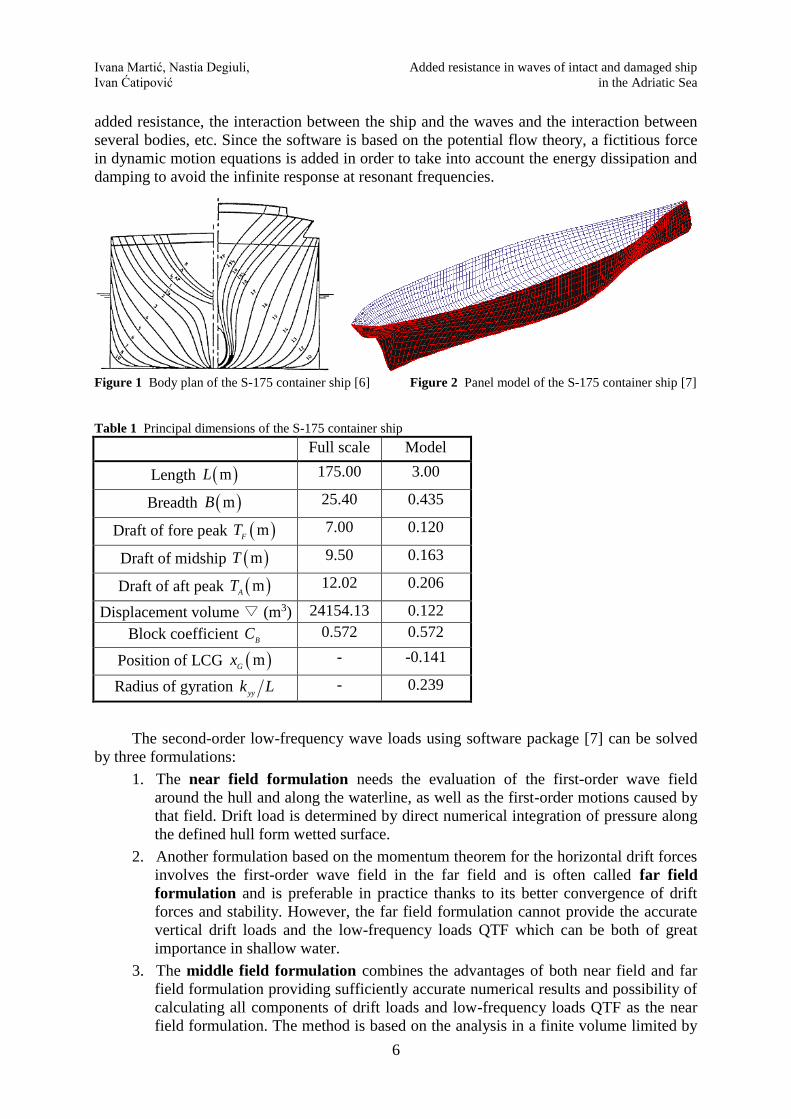
given in Table 1 and the body plan is shown in Figure 1. The hull mesh created using
hydrodynamic software [7] is shown in Figure 2.
In order to numerically calculate the added resistance, hydrodynamic software was used
[7]. The software is based on the potential flow theory and provides the solutions of the first-
and second-order motions and loads. The hull characteristics and parameters of the waves are
necessary as an input. It allows calculation of diffraction and radiation components of the ship
Ivana Martić, Nastia Degiuli, Added resistance in waves of intact and damaged ship
Ivan Ćatipović in the Adriatic Sea
6
added resistance, the interaction between the ship and the waves and the interaction between
several bodies, etc. Since the software is based on the potential flow theory, a fictitious force
in dynamic motion equations is added in order to take into account the energy dissipation and
damping to avoid the infinite response at resonant frequencies.
Figure 1 Body plan of the S-175 container ship [6] Figure 2 Panel model of the S-175 container ship [7]
Table 1 Principal dimensions of the S-175 container ship
Full scale Model
Length mL 175.00 3.00
Breadth mB 25.40 0.435
Draft of fore peak mF
T 7.00 0.120
Draft of midship mT 9.50 0.163
Draft of aft peak mA
T 12.02 0.206
Displacement volume ∇ (m3) 24154.13 0.122
Block coefficient B
C 0.572 0.572
Position of LCG mG
x - -0.141
Radius of gyration yy
k L - 0.239
The second-order low-frequency wave loads using software package [7] can be solved
by three formulations:
1. The near field formulation needs the evaluation of the first-order wave field
around the hull and along the waterline, as well as the first-order motions caused by
that field. Drift load is determined by direct numerical integration of pressure along
the defined hull form wetted surface.
2. Another formulation based on the momentum theorem for the horizontal drift forces
involves the first-order wave field in the far field and is often called far field
formulation and is preferable in practice thanks to its better convergence of drift
forces and stability. However, the far field formulation cannot provide the accurate
vertical drift loads and the low-frequency loads QTF which can be both of great
importance in shallow water.
3. The middle field formulation combines the advantages of both near field and far
field formulation providing sufficiently accurate numerical results and possibility of
calculating all components of drift loads and low-frequency loads QTF as the near
field formulation. The method is based on the analysis in a finite volume limited by
Added resistance in waves of intact and damaged ship Ivana Martić, Nastia Degiuli,
in the Adriatic Sea Ivan Ćatipović
the hull and a control surface surrounding the hull. Pressure integration over the hull
surface is evaluated with a semi-analytical method using the far field potentials like
the previous formulation.
The low-frequency wave loading ( )F t is evaluated in time domain after the
determination of the quadratic transfer function QTF and complex amplitudes and it is defined
by a double summation [9]:
' *
1 1
( ) exp ( )ij
N N
i j i ji j
F t F a a i t
(10)
where '
ijF is the drift force in waves,
ia is the complex amplitude of incoming wave, *
ja is the
complex conjugate amplitude of incoming wave, ,i j
are the incoming wave frequencies.
Within this study only the constant part of the quadratic transfer function QTF is taken into
account, i.e. the diagonal elements of QTF matrix which represent the drift forces in waves as
constant values at certain frequencies.
The added resistance force in waves is defined as: ' 2( )jj j
F t F a (11)
where j
a is the amplitude of head incoming waves.
Finally, the added resistance coefficient in waves is given by the following relation:
2 2
( )
/XW
j
F tC
ga B L (12)
where is the density of water, g is the gravity acceleration, B is the model breadth, L is
the model length.
In this paper previously described numerical procedure is used to calculate constant part
of the second-order wave load which represents added resistance due to waves.
The calculations are conducted for four Froude numbers and four velocities of the S-175
container ship model shown in Table 2. Based on the model test data, regular head waves
were applied on the model. The frequencies of generated incoming waves were determined on
the basis of the range of the ratio / 0.3 2.0L [6]. Wave frequencies were calculated
using the dispersion equation for a limited depth of water considering that the model was
tested in a tank of 3.5 meters depth.
Table 2 Froude numbers and velocities of the S-175 container ship model
Froude number Fr Velocity v, m/s
0 0
0.087 0.472
0.148 0.803
0.198 1.074
The comparison of the calculation results of added resistance coefficients obtained by
using different methods and experimentally obtained coefficients is shown in Figures 3-6
based on the ratio of the wavelength and the length of the model.
The abbreviations of the aforementioned methods of calculating the second-order low-
frequency wave loads are the following:
Ivana Martić, Nastia Degiuli, Added resistance in waves of intact and damaged ship
Ivan Ćatipović in the Adriatic Sea
8
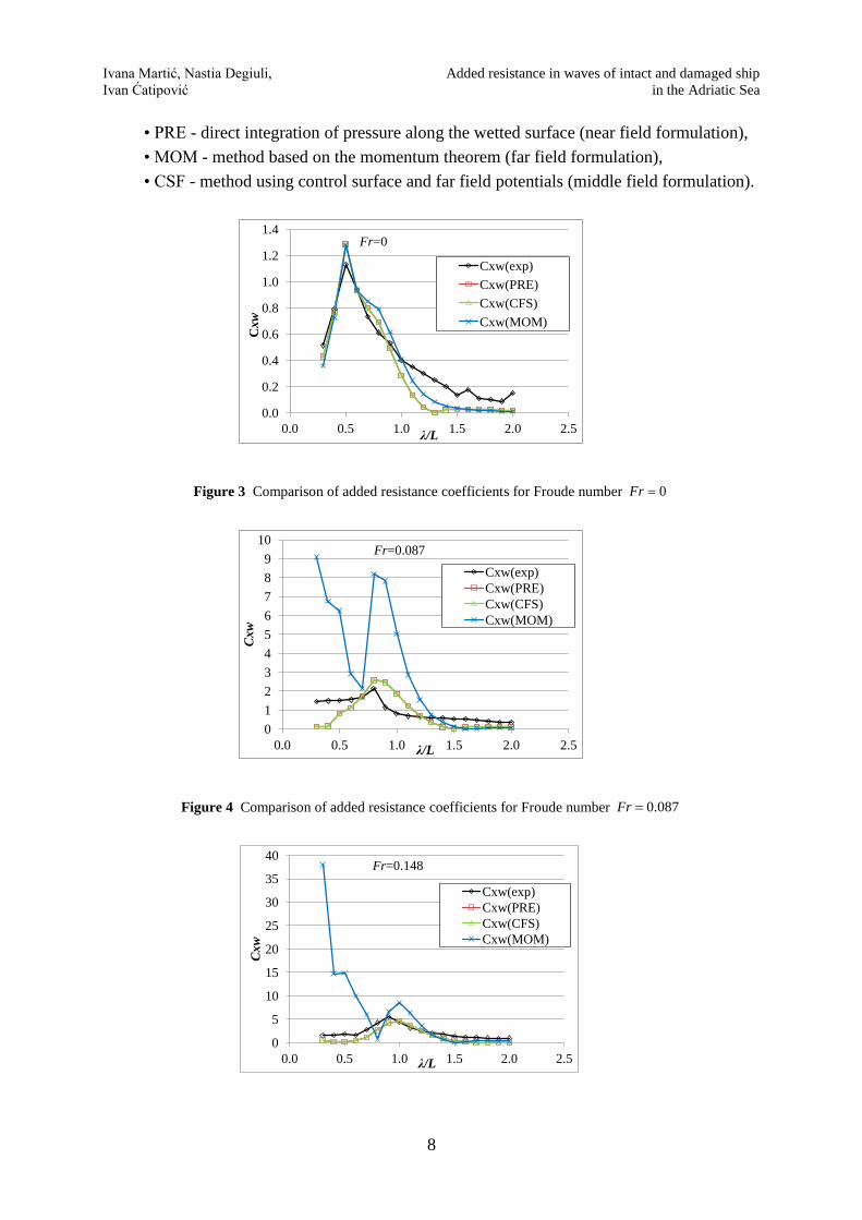
• PRE - direct integration of pressure along the wetted surface (near field formulation),
• MOM - method based on the momentum theorem (far field formulation),
• CSF - method using control surface and far field potentials (middle field formulation).
0.0
0.2
0.4
0.6
0.8
1.0
1.2
1.4
0.0 0.5 1.0 1.5 2.0 2.5
Cxw
λ/L
Cxw(exp)
Cxw(PRE)
Cxw(CFS)
Cxw(MOM)
Fr=0
Figure 3 Comparison of added resistance coefficients for Froude number 0Fr
0
1
2
3
4
5
6
7
8
9
10
0.0 0.5 1.0 1.5 2.0 2.5
Cxw
λ/L
Cxw(exp)
Cxw(PRE)
Cxw(CFS)
Cxw(MOM)
Fr=0.087
Figure 4 Comparison of added resistance coefficients for Froude number 0.087Fr
0
5
10
15
20
25
30
35
40
0.0 0.5 1.0 1.5 2.0 2.5
Cxw
λ/L
Cxw(exp)
Cxw(PRE)
Cxw(CFS)
Cxw(MOM)
Fr=0.148
Added resistance in waves of intact and damaged ship Ivana Martić, Nastia Degiuli,
in the Adriatic Sea Ivan Ćatipović
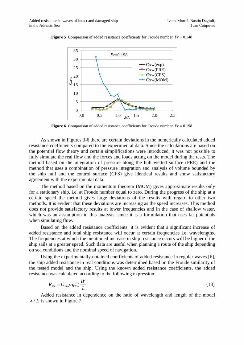
Figure 5 Comparison of added resistance coefficients for Froude number 0.148Fr
0
5
10
15
20
25
30
35
0.0 0.5 1.0 1.5 2.0 2.5
Cxw
λ/L
Cxw(exp)
Cxw(PRE)
Cxw(CFS)
Cxw(MOM)
Fr=0.198
Figure 6 Comparison of added resistance coefficients for Froude number 0.198Fr
As shown in Figures 3-6 there are certain deviations in the numerically calculated added
resistance coefficients compared to the experimental data. Since the calculations are based on
the potential flow theory and certain simplifications were introduced, it was not possible to
fully simulate the real flow and the forces and loads acting on the model during the tests. The
method based on the integration of pressure along the hull wetted surface (PRE) and the
method that uses a combination of pressure integration and analysis of volume bounded by
the ship hull and the control surface (CFS) give identical results and show satisfactory
agreement with the experimental data.
The method based on the momentum theorem (MOM) gives approximate results only
for a stationary ship, i.e. at Froude number equal to zero. During the progress of the ship at a
certain speed the method gives large deviations of the results with regard to other two
methods. It is evident that these deviations are increasing as the speed increases. This method
does not provide satisfactory results at lower frequencies and in the case of shallow water,
which was an assumption in this analysis, since it is a formulation that uses far potentials
when simulating flow.
Based on the added resistance coefficients, it is evident that a significant increase of
added resistance and total ship resistance will occur at certain frequencies i.e. wavelengths.
The frequencies at which the mentioned increase in ship resistance occurs will be higher if the
ship sails at a greater speed. Such data are useful when planning a route of the ship depending
on sea conditions and the nominal speed of navigation.
Using the experimentally obtained coefficients of added resistance in regular waves [6],
the ship added resistance in real conditions was determined based on the Froude similarity of
the tested model and the ship. Using the known added resistance coefficients, the added
resistance was calculated according to the following expression: 2
2
AW XW a
BR C g
L (13)
Added resistance in dependence on the ratio of wavelength and length of the model
/ L is shown in Figure 7.

Ivana Martić, Nastia Degiuli, Added resistance in waves of intact and damaged ship
Ivan Ćatipović in the Adriatic Sea
10
0
20
40
60
80
100
120
140
160
180
200
0.0 0.5 1.0 1.5 2.0 2.5
RAW
, kN
λ/L
Fr=0.0
Fr=0.087
Fr=0.148
Fr=0.198
Figure 7 The ship added resistance for different Froude numbers
5. Added resistance of intact and damaged ship at defined sea states
A damaged ship often needs to be removed by towing after a maritime accident. The
water that has penetrated inside the hull not only affects and threatens the stability of the ship,
but has also an impact on the ship seakeeping characteristics. It is necessary to know what
impact has the fluid inside the hull that moves along with the ship on the global motions and
loads in order to determine the method and route of towing.
Determination of seakeeping characteristics in this case is based on the coupled motions
of ship motions as a rigid body and fluid sloshing inside the tank. Hydrodynamic problem of
solving the coupled motions and loads of the ship and internal fluid inside the tanks is also
considered under assumptions of linear potential flow theory. Sloshing and seakeeping of the
ship are two separately observed hydrodynamic parts. Since a linear potential flow theory is
considered, within the tanks there is no damping and the problem of resonant frequencies of
fluid motion in the tank and possibly unrealistic responses to these frequencies may occur. It
is therefore necessary to correct the hydrodynamic model by using damping factors which
may be based on empirical data or experimental tests.
Hydrostatic forces and moments acting on the vessel shall be determined by integrating
the pressure along the hull wetted surface. Hydrodynamic loads acting on the ship can be
determined based on flow velocity potential of wave diffraction and its components and
radiation potential.
In the case of sloshing inside the tank, a similar procedure is used to determine the
hydrodynamic and hydrostatic loads. Since according to the liner theory the free surface of a
fluid inside the tank is constantly horizontal, a correction of the tank walls vertical coordinates
is used in the integration of pressure along the wetted surface of the walls. The calculations
are conducted based on the center of the free surface of liquid inside the tank.
In order to simulate the impact of sloshing inside the hull due to damage, a flooded tank
is generated inside the mesh of the S-175 container ship as shown in Figure 8. The volume of
liquid in the tank is 48.49% of the volume displacement of the undamaged ship on a draft
equal to 12.01667 mT , or 32.74% of the volume displacement of the damaged ship that has
vertically immersed for 3.483 mT .

Added resistance in waves of intact and damaged ship Ivana Martić, Nastia Degiuli,
in the Adriatic Sea Ivan Ćatipović
Figure 8 Panel model of the S-175 container ship with internal tank [7]
Fluid inside the tank was first treated as the ship added displacement mass but without
affecting the global motions and loads. After that, the seakeeping characteristics of the ship
were calculated considering also the sea water inside the tank in order to determine the impact
of motion and loads of liquid in the tank on global ship motions at a defined sea state. The
calculation is based on the Tabain wave spectrum as a modification of JONSWAP (Joint
North Sea Wave Project) spectrum for the Adriatic Sea to assess the safety of towing the ship
in the sea conditions characteristic for the Adriatic Sea.
The Tabain wave spectrum is defined as follows:
4 2
1 3
5.1862
5
0.01350.862 1.63
H pgS e
(14)
where
2
2 22
m
mp e
(15)
1/3
1.80.32
0.60m
H
(16)
0.08 for
0.1 for
m
m
>
(17)
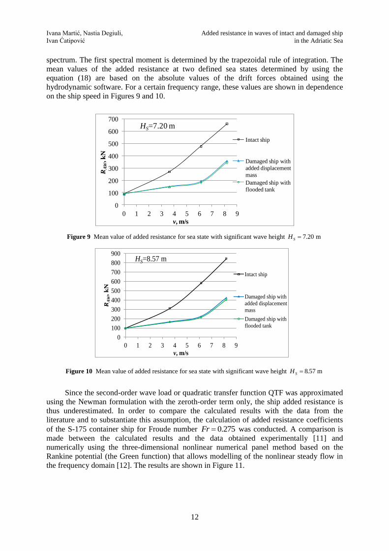
According to theoretical predictions the most likely maximum significant wave height
for the period of 20 years is 7.20 m and for the period of 100 years it is 8.57 m [10]. For sea
states with the aforementioned significant wave heights, the mean value of added resistance of
the intact and the damaged S-175 container ship is calculated. The mean added resistance is
determined based on a summation or an integration of the contributions over the whole
frequency range as follows [8]:
20
2 ( ) ( )dAW
AW
a
RR S
(18)
where 2
( )AW
a
R
stands for drift force at certain wave frequency obtained using hydrodynamic
software [7].
Relation between the mean added resistance and the regular wave amplitude squared is
linear, and the wave spectrum is assumed to be ideal. The spectral function is obtained by
multiplying drift force at certain frequency and the corresponding ordinate of the Tabain
Ivana Martić, Nastia Degiuli, Added resistance in waves of intact and damaged ship
Ivan Ćatipović in the Adriatic Sea
12
spectrum. The first spectral moment is determined by the trapezoidal rule of integration. The
mean values of the added resistance at two defined sea states determined by using the
equation (18) are based on the absolute values of the drift forces obtained using the
hydrodynamic software. For a certain frequency range, these values are shown in dependence
on the ship speed in Figures 9 and 10.
0
100
200
300
400
500
600
700
0 1 2 3 4 5 6 7 8 9
RAW
, k
N
v, m/s
Intact ship
Damaged ship with
added displacement
mass
Damaged ship with
flooded tank
HS=7.20 m
Figure 9 Mean value of added resistance for sea state with significant wave height 7.20 mSH
0
100
200
300
400
500
600
700
800
900
0 1 2 3 4 5 6 7 8 9
RA
W,
kN
v, m/s
Intact ship
Damaged ship with
added displacement
mass
Damaged ship with
flooded tank
HS=8.57 m
Figure 10 Mean value of added resistance for sea state with significant wave height 8.57 mSH
Since the second-order wave load or quadratic transfer function QTF was approximated
using the Newman formulation with the zeroth-order term only, the ship added resistance is
thus underestimated. In order to compare the calculated results with the data from the
literature and to substantiate this assumption, the calculation of added resistance coefficients
of the S-175 container ship for Froude number 0.275Fr was conducted. A comparison is
made between the calculated results and the data obtained experimentally [11] and
numerically using the three-dimensional nonlinear numerical panel method based on the
Rankine potential (the Green function) that allows modelling of the nonlinear steady flow in
the frequency domain [12]. The results are shown in Figure 11.

Added resistance in waves of intact and damaged ship Ivana Martić, Nastia Degiuli,
in the Adriatic Sea Ivan Ćatipović
0.0
2.0
4.0
6.0
8.0
10.0
12.0
0.5 1.0 1.5 2.0
RA
W/ρ
gζ a
2B
2/L
λ/L
RAW/ρgζa2B2/L
S175 - Liu 2011
S175 - EXP
Figure 11 Comparison of obtained results of added resistance coefficients with data from literature
[11], [12]
It can be concluded from Figure 11 that the curve form of the calculated values of
dimensionless added resistance follows the trend of the experimental and numerical data from
the literature. Since in this paper added resistance is based on the potential theory, there are
certain deviations in relation to the experimental data. It may also be noted that the extreme
value of the resulting dimensionless function of added resistance in dependence on the ratio
/ L occurs at a lower / L ratio than in the case of the numerical and experimental data
from the literature.
6. Conclusion
Three methods available in the software package [7] were used to calculate the ship
added resistance. While the method that uses the direct integration of pressure along the hull
wetted surface and the method that analyzes the finite volume around the ship within the
control surfaces in conjunction with the integration of the pressure give similar results
compared to the experimental data, the method which uses the momentum theorem provides a
significant deviation from the experimental results, except in the case of the stationary ship.
As the method of momentum theorem uses far potentials, it is almost unusable in the case of
shallow water.
The quadratic transfer function QTF that represents low-frequency wave loads is
approximated by zeroth-term only or drift force which is constant at a given frequency of
incoming wave. This, the so called Newman’s approximation simplifies the calculation of
added resistance but also significantly underestimates the ship added resistance. Since only
the head waves were generated in this paper, it was assumed that Newman’s approximation of
QTF function would provide satisfactory accuracy of the second-order wave loads. Based on
the obtained results of the added resistance of the intact and the damaged ship at defined sea
states, it can be concluded that the two calculation models used in this paper, i.e. damage
simulated as increased displacement mass and as a flooded tank, give approximately the same
results. The intact ship has a significantly larger added resistance than the damaged ship.
Since the damaged ship with a larger displacement mass and declining natural frequency has
significant response at lower frequencies where the spectral energy at certain sea state is
lower, the added resistance will be also smaller than the added resistance of the intact ship.
It is necessary to adjust the boundary conditions and carefully determine the damping
factor which will prevent infinite responses especially in the case of sloshing inside the ship

Ivana Martić, Nastia Degiuli, Added resistance in waves of intact and damaged ship
Ivan Ćatipović in the Adriatic Sea
14
tank. Despite numerous simplifications, the linear potential flow theory gives satisfactory
results and greatly simplifies the calculation of the interaction of the ship and incoming
waves.
AKNOWLEDGMENTS
This work has been supported in part by the Croatian Science Foundation under the project
8658.
REFERENCES
[1] Prpić-Oršić, J., Čorić, V.: Pomorstvenost plovnih objekata, Zigo, Rijeka, 2006.
[2] Degiuli, N., Ćatipović, I., Martić, I., Werner, A., Čorić, V.: Influence of added resistance in regular waves
on ship fuel consumption, Proceedings of the 9th Conference on Sustainable Development of Energy,
Water and Environment, 9th SDEWES Conference, Venice-Istanbul, 2014.
[3] Alexandersson, M.: A Study of Methods to Predict Added Resistance in Waves, M.Sc. Thesis, KTH
Centre for Naval Architecture, Stockholm, 2009.
[4] Matulja, D., Sportelli, M., Prpić-Oršić, J., Guedes Soares, C.: Methods for estimation of ships added
resistance in regular waves, Proceedings of 19th Symposium of Theory and Practice of Shipbuilding (In
memoriam Prof. Leopold Sorta), SORTA 2010, Lumbarda, Korčula Island, Croatia, 2010.
[5] Kashiwagi, M., Ikeda, T., Sasakawa, T.: Effects of Forward Speed of a Ship on Added Resistance in
Waves, International Journal of Offshore and Polar Engineering, Vol. 20, No. 3, 2010., pp. 196-203.
[6] Nakayama, Y., Yasukawa, H., Hirata, N. and Hata, H.: Time Domain Simulation of Wave-induced
Motions of a Towed Ship in Head Seas, Proceedings of the Twenty-second (2012) International Offshore
and Polar Engineering Conference, 22nd ISOPE Conference Rhodes, Greece, June 2012, pp. 901-907.
[7] HYDROSTAR for Experts, v6.11, 2010. Bureau Veritas, Paris.
[8] Journée, J.M.J., Massie W.W.: Offshore Hydromechanics, Delft University of Technology, Delft, The
Netherlands, 2001.
[9] Chen, X. B. and Rezende, F.: Computations of low-frequency wave loading, Proceedings of the 23rd
International Workshop on Water Waves and Floating Bodies, 23rd IWWWFB, Jeju, Korea, 2008.
[10] Parunov, J., Senjanović, I.: Wave loads on oil tankers in the Adriatic Sea, Proceedings of the 1st
Conference on Marine Technology in Memory of Academician Zlatko Winkler, Rijeka, 2005, pp. 98-111.
[11] Feng, P., Ma, N., Gu, X.: A practical method for predicting the propulsive performance of energy
efficient ship with wave devouring hydrofoils at actual seas, Proceedings of the Institution of Mechanical
Engineers, Part M: Journal of Engineering for the Maritime Environment, 2013.
[12] Liu, S., Papanikolaou, A., Zaraphonitis, G.: Prediction of added resistance of ships in waves, Ocean
Engineering, Vol. 38, No. 4, 2011, pp. 641-650.
Submitted: 12.01.2015.
Accepted: 14.04.2015.
Ivana Martić
Nastia Degiuli, [email protected]
Ivan Ćatipović
University of Zagreb,
Faculty of Mechanical Engineering and Naval Architecture,
Ivana Lučića 5, 10000 Zagreb, Croatia