adaptive resonant vibration control of a piezoelectric ... · pdf fileof a piezoelectric...
TRANSCRIPT

Adaptive Resonant Vibration Controlof a Piezoelectric Flexible Plate ImplementingFiltered-X LMS AlgorithmZhi-cheng Qiu and Biao MaSchool of Mechanical and Automotive Engineering, South China University of Technology, Guangzhou 510641,PR China
(Received 3 July 2013; revised: 15 November 2013; accepted: 2 December 2013)
Vibration in aerospace structures can lead to structural damage. To solve this problem, the implementation of activevibration control must be considered. This paper investigates active vibration control under the persistent resonantexcitation of a clamped-clamped piezoelectric plate system. The finite element method (FEM) and ANSYS modalanalysis methods are utilized to obtain the dynamics model and mode shapes of the plate. A two-norm criterion isused for optimal placement of piezoelectric sensors and actuators, taking into account the non-controlled modes toreduce spillover problems. A genetic algorithm (GA) is used to search the optimal locations of actuators/sensors.Then, a proportional derivative (PD) control algorithm and a filtered-X least mean square (filtered-X LMS) feed-forward control algorithm are designed for the system. Subsequently, numerical simulations with optimal place-ment of actuators and sensors are carried out to compare the performance of the controllers. Finally, experimentsare conducted. The experimental results demonstrate that the designed filtered-X LMS control algorithms cansuppress the resonant vibration better than that of the PD control.
1. INTRODUCTION
Flexible structures are widely used in industrial applicationsand aerospace structures.1, 2 Flexible structures have the advan-tages of light weight and low energy consumption. Nowadaysflexible space structures are developing towards the directionof large scale, flexibility, and low stiffness. However, vibra-tion is easily caused by external disturbance due to the lowstiffness and small damping of the material.3, 4 Moreover, adynamic aeroelastic instability phenomenon results from theinteractions between motions of an aircraft panel and aerody-namic loads exerted on that panel by air flowing past one of thefaces, which is called panel flutter.5, 6 Vibration and flutter willlead to unwanted displacements, positioning errors, and evenworse, lead to the destructive damage of the structure.2 Espe-cially, when the structure vibrates at its resonance frequencies,the structural working life will be greatly shortened. There-fore, active vibration control must be applied to guarantee thenormal working of flexible structures.
The vibration problem has motivated a huge amount of re-search in the vibration control of flexible structures, and a greatamount of work has been conducted in the field of smart struc-tures by many researchers. Forward first used the piezoelectricceramics in the vibration control of an end-supported mast.7
Bailey and Hubbard designed an active vibration damper for acantilever beam using polyvinylidene fluoride (PVDF) film asa distributed-parameter actuator.8 An optimal control design ispresented by Zhou et al. to actively suppress large-amplitude,limited-cycle flutter motions of rectangular isotropic plates atsupersonic speeds using piezoelectric actuators.6 The resultsdemonstrate that the piezoelectric materials show good perfor-mance in panel flutter suppression. Li used the piezoelectricmaterial to improve the flutter characteristics of the supersonicplates.9 The numerical results showed that the aeroelastic flut-ter properties can be greatly improved by introducing active
stiffness and active mass into the supersonic plate with piezo-electric patches.
At present, researches on vibration control mainly lie inmodelling methods of the mathematical model, optimal place-ment of actuators/sensors, and control algorithms.10–12 Thelocations of the actuators/sensors have a significant influenceon the performance of the control system. Misplaced actu-ators/sensors may lead to problems such as lack of observ-ability and controllability. Researchers have used many op-timization criteria and techniques to find the optimal loca-tion of actuators/sensors. Arbel first proposed the concept ofcontrollability/observability in the optimal placement of actu-ators/sensors.13 Bruant and Proslier proposed a modified op-timization criterion in consideration of the spillover effects.14
Some researchers have also suggested other optimization cri-terion based on H2 or H∞ norms.15–17 There are also manyother optimization criterion such as the minimization of thelinear quadratic regulator cost18 and the maximization of theharvested strain energy in piezoceramic materials.19 In addi-tion, the genetic algorithm (GA) has been extensively used infinding the optimal places of the actuators/sensors.20, 21
There are many control algorithms utilized to suppress thevibration of flexible structures. Warminski et al. studied fourtypes of control algorithms for the vibration suppression of alarge, flexible composite beam structure.22 Shin et al. de-signed an acceleration feedback (AF) controller for a clamped-clamped beam.23 Lin and Liu presented a novel resonant fuzzylogic controller (FLC) to minimize structural vibration usingcollocated piezoelectric actuator/sensor pairs.24 The experi-mental results demonstrated the effectiveness of the FLC inactive vibration control. Qiu et al. studied a kind of discrete-time sliding mode variable structure control (VSC) algorithmto suppress vibration of a flexible plate.25 The experimentsdemonstrated that the proposed control algorithm is feasible
224 (pp. 224–239) International Journal of Acoustics and Vibration, Vol. 19, No. 4, 2014

Z. Qiu, et al.: ADAPTIVE RESONANT VIBRATION CONTROL OF A PIEZOELECTRIC FLEXIBLE PLATE IMPLEMENTING FILTERED-X. . .
and efficient in active vibration control. Time delay exists inactive control systems, instability may occur if the time delayis neglected in controller design. Kun et al. presented a theo-retical and experimental study of the delayed positive feedbackcontrol technique using a flexible plate as the research object.26
Tong et al. designed an H∞ time-delay controller for a flexi-ble plate.27 The feasibility and effectiveness of the time-delaycontroller are demonstrated by numerical simulations and ex-periments. Ji et al. proposed an adaptive semi-active SSDV(Synchronized Switch Damping on Voltage) method based onthe LMS algorithm and applied the algorithm to the vibrationcontrol of a composite beam.28
Currently, adaptive control methods in active vibration andnoise are widely used. The adaptive feed-forward control al-gorithm29 is widely used in active resonance vibration con-trol under persistent excitation, which was first presented byWidrow and Stearns.30 A reference signal is needed in theoperation process of a filtered-X LMS algorithm. Unfortu-nately, it is hard to get in a practical application. Model er-rors of the control path may lead to unstable systems or anincreased signal error. However, the algorithm is particularlyeffective in suppressing harmonic vibration and is easy to berealized despite the above-mentioned shortcomings. Andersonand How applied the combined filtered-X LMS feed-forwardand feedback control algorithm to the spacecraft vibration iso-lation platform.31 Zhu et al. used the multi-input multi-output(MIMO) filtered-U least mean square (filtered-U LMS) algo-rithm to control the vibration of a cantilever smart beam.32
Ma implemented a novel adaptive filtering algorithm in a can-tilever beam bonded with piezoelectric patches and comparedwith the least mean square algorithm; satisfactory vibration re-duction was achieved in different situations.33 Carra et al. ap-plied the filtered-X LMS algorithm in a rectangular aluminiumplate vibrating in air or in contact with water.34 Satisfactoryreductions of the error signals were obtained in the experi-ments in the case of an empty tank. The control action pro-duced lower effects while introducing water to the tank. Ohet al. presented the active vibration control of a flexible can-tilever beam using one piezoceramic actuator bonded on thebeam and an adaptive controller based on the filtered-X LMSalgorithm.35 The control results indicated that a considerablevibration reduction could be achieved in a few seconds. Theperformance of the filtered-X LMS algorithm for suppressingwing vibration and flutter was investigated by Carnahan andRichards.36 The control method showed good performance insuppressing wing vibration and flutter.
In industrial applications, it is hard to get an accurate dy-namical model of controlled systems. Both the filtered-X LMSand the filtered-U LMS control algorithms are effective in sup-pressing the vibration of these systems. Das et al. proposed anew virtual FXLMS algorithm for a virtual microphone.37 Thecomparison of the FXLMS algorithm with FULMS is theoret-ically analysed and experimentally validated using a cantileverbeam by Huang et al.38 The difference between the two algo-rithms mainly lies in the structure of the filters. The filtered-XLMS algorithm is based on the finite impulse response (FIR)filter; while the filtered-U LMS algorithm is based on the infi-nite impulse response (IIR) filter. The influence on the refer-ence signal caused by control output feedback will be reflectedby poles in transfer function. Since the transfer function of theFIR filter is a full zeros expression, the FIR filter could not
eliminate the influence to the reference signal caused by con-trol output feedback. Therefore, the FIR model is suitable forthe adaptive filtering feed-forward control method. Comparedwith the FIR filter, the IIR filter with zeros and poles couldcompensate the feedback effect.
The filtered-X LMS algorithm has the merits of a high-controlling correction rate, good robustness to uncertainties,and fast speed of tracking external disturbance. Moreover,this algorithm is easy to implement with its simple structure.Therefore, it is suitable to implement the filtered-X LMS al-gorithm to the clamped-clamped piezoelectric plate system inthis paper. However, the interference source in the filtered-XLMS is supposed to be measurable and used as the referencesignal, and this is not unrealistic in some applications. As acomparison, the filtered-U LMS control algorithm is more suit-able for applications in which the interference source cannot bemeasured directly. It has better convergence and control per-formance than the filtered-X LMS algorithm when feedbackis present. The control performance for the clamped-clampedplate of the filtered-U LMS control algorithm will be studiedin our future work for comparison with the filtered-X LMS al-gorithm.
This paper aims at suppressing the resonance vibration ofa clamped-clamped plate under resonant sinusoidal excitation.Optimal placement of the actuators and sensors is processedbased on the finite element mathematical model using an H2
norm criterion. Then the PD controller and filtered-X LMScontroller are designed. Both simulations and experiments arecarried out to compare the performance of the two designedcontrol algorithms.
The contributions of this paper are as follows: (a) the modelof a piezoelectric clamped-clamped plate used to simulatepanel flutter analysis is obtained by FEM. The FEM modelis used for the optimization of piezoelectric sensors/actuatorsand simulations of control algorithms. (b) A kind of actua-tors/sensors optimal placement method based on the genetic al-gorithm is investigated. The waste time for searching the opti-mal positions is very short when the index of the maximal con-trolled modes and the index of minimal non-controlled modesare obtained. (c) Simulations and experiments are conductedto validate the effectiveness of the filtered-X LMS controller insuppressing the resonant vibration of a clamped-clamped plateunder persistent excitation. A PD controller is also designedas a comparison. The results show that both the designedcontrollers could suppress resonant vibration effectively; thefiltered-X LMS controller shows a better performance.
The rest of the paper is organized as follows. In Section 2,the finite element model of a clamped-clamped plate bondedwith piezoelectric actuators and sensors is derived. In Sec-tion 3, the optimal criterion used for the placement of the ac-tuators and sensors and the GA used for searching for a glob-ally optimal solution are described. A numerical simulationof a clamped-clamped plate is performed. In Section 4, thefiltered-X LMS control algorithm is employed. The numericalsimulation results of PD control and filtered-X LMS controlare provided. In Section 5, a clamped-clamped plate setup isconstructed. Experiments are conducted by using the designedPD control and the filtered-X LMS control algorithms. Finally,the conclusion is drawn in Section 6.
International Journal of Acoustics and Vibration, Vol. 19, No. 4, 2014 225

Z. Qiu, et al.: ADAPTIVE RESONANT VIBRATION CONTROL OF A PIEZOELECTRIC FLEXIBLE PLATE IMPLEMENTING FILTERED-X. . .
Figure 1. Three-dimensional model and schematic diagram of the system.
2. SYSTEM DESCRIPTION AND FINITEELEMENT MODELLING
2.1. Description of a Clamped-ClampedFlexible Plate System
Figure 1 shows the three-dimensional model and theschematic diagram of the system. It should be emphasizedthat the PZT actuators/sensors are glued after the optimiza-tion analysis in Section 3.3. Furthermore, PZT actuators aresurface-bonded symmetrically on the top and bottom surfacesof the plate. The working principle of the system can be de-scribed as follows. Firstly, the disturbance is measured by thePZT sensor in the control side. The signal from the sensor isconverted into the voltage signal by using a charge amplifier.Through an A/D converter circuit, the analogue signal is trans-formed to the digital signal and then transferred into the ARMcontroller. The ARM controller will transmit the signal to thecomputer. By running the algorithm, the computer calculates acontrol output, which will be sent to the ARM controller, D/Aconverter, and PZT drive power supply in sequence.
A four-node rectangular element is used to build up themodel of the system. The element meshing and node are num-bered for the clamped-clamped plate, as shown in Fig. 2. Theplate is modelled using the finite element method (FEM). It isdiscretized by using a four-node rectangular element based onthe Kirchhoff plate theory. Each node has three degrees of free-dom, corresponding to the transverse displacement w, rotationangles θx = ∂w/∂y and θy = −∂w/∂x.
2.2. Piezoelectric Plate Model Derived byusing FEM
Since the investigated piezoelectric clamped-clamped flexi-ble plate is excited by PZT actuators, there is no external forceapplied to the plate system in the present case. The elementdynamics equation is
mqe + kqe = kave · V ae + kavc · V ac; (1)
where m is the mass matrix of a piezoelectric plate element;k is the stiffness matrix of a piezoelectric plate element; V ae
is the excited voltage applied to the PZT actuator used for ex-citation; V ac is the control voltage applied to the PZT actuatorused for control; kave and kavc are the coefficient vectors of theinternal excitation force and control force, respectively.
From the element meshing and node numbering of theclamped-clamped plate illustrated in Fig. 2, the plate is dividedinto 816 elements. There are 25 nodes in the length directionand 35 nodes in the width direction. Each node has three de-grees of freedom. As shown in Fig. 2, the boundary conditionof the plate is clamped-free-clamped-free (CFCF). By apply-ing the boundary condition to the plate system, one should con-strain all the degrees of freedom of nodes on the two edges ofthe plate along the Y direction, i.e., nodes from 1 to 35 and841 to 875 are constrained.
Assembling all the plate elements and the piezoelectric ele-ments under the consideration of the boundary condition, onecan obtain the dynamics equation of the piezoelectric clamped-clamped plate as
Mq + Cq + Kq = FAE + FAC; (2)
226 International Journal of Acoustics and Vibration, Vol. 19, No. 4, 2014

Z. Qiu, et al.: ADAPTIVE RESONANT VIBRATION CONTROL OF A PIEZOELECTRIC FLEXIBLE PLATE IMPLEMENTING FILTERED-X. . .
Figure 2. Element meshing and node numbering for a clamped-clamped plate.
where M ∈ R2415×2415 and K ∈ R2415×2415 are the globalmass matrix and stiffness matrix, respectively; q ∈ R2415×1
is the general coordinate vector; FAE ∈ R2415×1 and FAC ∈R2415×1 are the excitation force and control force vectors, re-spectively; C ∈ R2415×2415 is the damping matrix; C =αM+βK, α and β are the Rayleigh mass and stiffness damp-ing constants, respectively.
After assembling, the output voltage vector of the sensorscan be expressed as
Y(t) = Ksvq; (3)
where Y(t) =Y1(t) Y2(t) . . . Yns(t)
T, the subscript
ns denotes the number of sensors; Ksv is the coefficient matrixof piezoelectric sensors.
2.3. Modal Transformation and State SpaceFormulation
Using a modal transformation method, the coupled equationwill become the decoupled one to simplify the analysis. Thetransformation relation is
q = Φη; (4)
where Φ is the modal matrix, and η is the modal displacementvector.
Substituting Eq. (4) into Eq. (2) and Eq. (3), yields
Mη + Cη + Kη = FAE + FAC; (5)
andY(t) = KsvΦη; (6)
where M = ΦTMΦ, K = ΦTKΦ, C = ΦTCΦ are diago-nal matrices corresponding to the mass, stiffness, and dampingmatrices, respectively; FAE = ΦTFAE and FAC = ΦTFACare the generalized excitation force vector and the generalizedcontrol force vector, respectively.
Equation (5) and Eq. (6) can be written as the state spacerepresentation as
X = AX + Bff + BuU
Y = CX; (7)
where X=
[ηη
]is the state vector; A=
[0 I
−M−1
K −M−1
C
]is the system matrix; Bf =
[0
M−1
ΦTKave
]is the excitation
force matrix; Bu =
[0
M−1
ΦTKavc
]is the control force ma-
trix; C =[0 KsvΦ
]is the output matrix; f = Vae and
U = Vac are the excited and control voltages, respectively.Furthermore, the matrices A, Bf, Bu and C can also be writ-
ten as
A =
[0 I−Ω2 −2ςΩ
], Bf =
[0
Bae
],
Bu =
[0
Bac
], C =
[0 Cs
]; (8)
where Ω = diag(ω1 ω2 . . . ωn), ς = diag(ς1 ς2 . . . ςn),in which diag(·) denotes diagonal operation; ωi, ςi are modalfrequency and damping ratio of the ith mode, respectively;Bae = M
−1ΦTKave; Bac = M
−1ΦTKavc; Cs = KsvΦ.
International Journal of Acoustics and Vibration, Vol. 19, No. 4, 2014 227

Z. Qiu, et al.: ADAPTIVE RESONANT VIBRATION CONTROL OF A PIEZOELECTRIC FLEXIBLE PLATE IMPLEMENTING FILTERED-X. . .
3. OPTIMIZATION OF PIEZOELECTRICSENSORS/ACTUATORS
3.1. H2 Norm Optimal Placement CriterionAssuming the state space representation of a system is
(A,B,C), when the damping ratio of the system meets thecondition ζ 1, the norm of the ith mode can be approxi-mately written as ∥∥Gi
∥∥2=
∥∥Bi
∥∥2
∥∥Ci
∥∥2
2√ζiωi
; (9)
where Gi is the transfer function of the system for the ithmode; B, C are equal to Bae, Cs expressed in Eq. (8).39
From Eq. (9), one can conclude that the norm of the ithmode is related to its modal frequency, damping ratio, con-trol coefficients, and sensor coefficients of the ith mode. Thenorm of the jth actuator for the ith mode is∥∥Gij
∥∥2=
∥∥Bij
∥∥2
∥∥Ci
∥∥2
2√ζiωi
. (10)
Obviously, the denominator in Eq. (10) is proportional tothe ith modal frequency. With the natural frequency increas-ing, the norms of higher modes are getting smaller and smallercompared with those of the lower modes. However, this maycause spillover problems, which are disadvantageous to thecontrolling of the system. Therefore, the H2 norm can not beused as the optimization criterion directly.
Normalization processing of theH2 norm is necessary. Nor-malization for the jth actuator for the ith mode is expressed as
δ2,ij =
∥∥Gij
∥∥22
max(∥∥Gij
∥∥22
) ; (11)
where i = 1, 2, . . . , n; j = 1, 2, . . . , ns; ns denotes the numberof actuators.15
In Eq. (11), δ2,ij can be explained as: the ratio between thenorm of the jth actuator and the maximum norm among all thecandidate actuators for the ith mode. The optimization crite-rion for the jth actuator is defined as
δ2,j =
n∑i=1
wiδ2,ij ; (12)
where wi is the selected weight of the ith mode.The weight wi can be positive or negative values. For the
controlled modes, wi is usually set as positive. The greater theweight is, the more important of the mode is. However, in or-der to reduce spillover problems and minimum energy for non-controlled modes, the weights should be set negative for thenon-controlled modes. Therefore, the algorithm would searchfor a position where not only the norms of the controlled modesare high, but also the norms of the non-controlled modes arelow.
3.2. Genetic Algorithm (GA)Genetic algorithm (GA) is a stochastic optimization algo-
rithm. It was formally presented by J. Holland in 1975.40 Orig-inating from Darwin’s biological theory of evolution, GA com-bines computer science with the biological theory of evolu-tion. The algorithm simulates the rule of survival-of-the-fittest
in nature and has the merits of global, parallelism, rapidity, andadaptability.
In view of the above-mentioned merits, GA is applied to findthe optimal locations of actuators. The genetic operations ofGA include selection, crossover, and mutation.21 Selection isan operation that chooses superior individuals from the initialpopulation as parents of next generation. The selection oper-ation is based on the fitness values of individuals. Those whohave bigger fitness values have bigger chances to be survived.
One should know that selection only selects superior indi-viduals but does not produce new individuals. To generate newindividuals, crossover and mutation are utilized. By selectingtwo individuals from the current population and interchang-ing part of the genes from the crossover points, two new in-dividuals are obtained. There are several crossover operationsincluding one-point crossover, uniform crossover, and arith-metic crossover. By crossover operation, the GA can move ina desirable direction. However, the probability of a crossovershould not be too big or too small. Generally, the probabilityof a crossover usually ranges from 0.59 to 0.99.
Selection and crossover operations complete most of thesearching work of the GA. Sometimes the GA may trap in alocal optimum when only selection and crossover operationsare used. To prevent the GA from getting trapped in a lo-cal optimum, a mutation operation is necessary. Mutation isan operation that changes one gene of an individual accordingto a specific probability of mutation. Similar to the selectedprobability of a crossover operation, the probability of a mu-tation operation should also be appropriately specified. If theprobability of mutation selected is bigger than 0.5, the GA willdegrade to a random search method.
The coordinates of an actuator (xj , yj) are chosen as the op-timization variables. The binary encoded method is used forGA. The length of the binary string depends on the searchingscope. The following operations describe how GA works inthis presentation. (a) The GA iteration firstly starts with a ran-domly selected population. Each individual consists of severalchromosomes corresponding to the actuators. Each chromo-some represents an actuator’s location, and it is encoded in thebinary form. In this investigation, each individual only has onechromosome. (b) Two members of the current population areselected as parents. The selected operation probability is de-termined by member’s fitness value. Those who have biggerfitness values have a bigger chance to be selected. (c) New off-springs are generated by the crossover operation between thetwo selected parents. (d) In order to improve the GA’s searchability, some genes of a child are changed randomly with arate, called mutation.
The GA stops if the iteration reaches the predefined value.Generally speaking, the result obtained from a limited numberof iterations may be a local optimum. Therefore, to get a resultwith a high confidence, one has either to run the GA processseveral times, each with randomly selected initial condition, orwith an increasing number of iterations.
3.3. Numerical Results of OptimalPlacement for Piezoelectric Patches
In this section, the optimal placement of a clamped-clampedplate is studied. The length of the plate between the twoclamped edges is 600 mm; the width of the plate is 510 mm;
228 International Journal of Acoustics and Vibration, Vol. 19, No. 4, 2014

Z. Qiu, et al.: ADAPTIVE RESONANT VIBRATION CONTROL OF A PIEZOELECTRIC FLEXIBLE PLATE IMPLEMENTING FILTERED-X. . .
Table 1. Material properties of the plate and piezoelectric patch.
Symbol Parameter Unit Piezoelectric patch PlateE Young’s modulus GPa 63 34.64ρ Density kg/m3 7650 1840υ Poisson ratio — 0.3 0.33
d31Piezoelectric m/V −166×10−12 —strain constant
Figure 3. Coordinates used for optimal placement.
and its thickness is 2 mm. Material properties of the plateand piezoelectric patch are listed in Table 1. Three dif-ferent sizes of the piezoelectric patch are employed as sen-sors and actuators. The size of actuators is of the samesize as 50 mm×15 mm×1 mm. The sizes of sensors are40 mm×10 mm×1 mm and 20 mm×6 mm×0.5 mm.
Since the piezoelectric patches break easily when placed inthe clamped edges in practical applications, the 68 elements inthe two clamped edges are not suitable to place PZT patches.When the piezoelectric patch is the same as that of the meshingelement size as meshed in Fig. 2, there are 740 candidate ele-ments that can be used to place the sensors and the actuatorsexcluding the 68 elements in the two clamped edges. These740 elements define the searching space for the GA. The vari-ables are defined as the numbers of the two nodes decided bythe location of a piezoelectric patch. The nodes are numberedfrom 0 to 21 in X direction, and numbered from 0 to 33 inY direction, as shown in Fig. 3. Then, they are encoded in abinary string. The string length is 6 bits, i.e., the location of apiezoelectric patch is expressed by a 12 bit binary string. Thefirst six binary strings and the rest of the binary strings corre-spond to the coordinate of actuator/sensor in x direction and ydirection, respectively. Figure 4 shows the typical encoding ofan actuator/sensor.
When the optimization criterion expressed in Eq. (12) isused, only the first three modes of vibration are considered.Only the first mode of vibration is selected as the control mode,and the other two modes as the non-controlled ones. In viewof minimum energy, the weights of the non-controlled modesshould be negative, while the weight of the first bending modeis positive.
In the GA operation, the parameters are selected as: thepopulation size is 20; the probability of crossover is 0.8; theprobability of mutation is set as 0.02; the maximum number ofgenerations is 100. The genetic operation process stops at thepredefined generation.
Figure 4. Typical encoding of actuator/sensor location.
Figure 5. GA results for optimal displacement.
From Fig. 5(a), it can be seen that the performance indexvalue converges to a constant value after 62 generations. TheGA can always find the optimal solution despite the existencesof suboptimal solutions. The optimal solution that the GAworks out shown in Fig. 5(b) is 0000000010000, i.e., the coor-dinates of the optimal solution are x = 0 and y = 16. SinceGA only searches one optimal solution each time. By runningGA for several times, one can get different optimal solutionsdue to the symmetry of the system.
In order to verify the validity of the GA, the enumerationmethod is used to calculate the performance index value ofevery candidate location. The results are displayed in Fig. 6.In Fig. 6, these elements that have negative performance in-dex values are unsuitable to place the actuators. Those whohave positive performance index values are more suitable toplace the actuators. Moreover, the bigger the performance in-dex value is, the more suitable the piezoelectric actuator can be
International Journal of Acoustics and Vibration, Vol. 19, No. 4, 2014 229

Z. Qiu, et al.: ADAPTIVE RESONANT VIBRATION CONTROL OF A PIEZOELECTRIC FLEXIBLE PLATE IMPLEMENTING FILTERED-X. . .
Figure 6. Performance index values using the enumeration method.
bonded. Obviously, the roots of the clamped-clamped plate inX direction have bigger performance index values, and thesevalues that near the middle of Y direction are almost the same.However, the numbers of the elements with the best indicesvalues are located in 51, 52, 765, and 766.
By comparing the optimal solution in the GA with the val-ues in Fig. 6, it can be seen that the two methods get the sameoptimization result. Although there are many suboptimal so-lutions in this system, the GA still finds the optimal locationof the piezoelectric patch effectively. Furthermore, the GA caneasily get global optimization results while solving complexproblems in comparison with other optimization techniques.
There are some points that need to be emphasized to guar-antee the robustness of the GA used to search the optimal lo-cations of actuators/sensors. The GA has good robustness forsolving global optimal problems commonly, while in solvingcomplex optimization problems, both early maturity and poorstability may occur in the GA. The GA is likely to convergeto a local optimum in the case of an inappropriate fitness func-tion. Here, the fitness function is the same as that of equationof Eq. (12) to achieve the global optimum quickly. The num-ber of the initial population is also very important. If the initialpopulation selected is too big, the GA will take a lot of timeto get the global optimum; otherwise if the initial population istoo small, the algorithm is likely to ignore the global optimum.To meet this condition, the initial population size is set as 20in this section.
For any specific optimization problems, the GA may con-verge much faster with the appropriate parameters. These pa-rameters include the crossover rate and the mutation rate. Toobig of a mutation rate will lead to the loss of the optimal so-lution, and too small of a mutation rate can cause prematureconvergence to the local optimal point. For the selection ofthese parameters, there are no practical limits. The crossoverrate is set as 0.8, and the mutation rate is set as 0.02, in thiscase. With the appropriate crossover rate and mutation rate,the GA can always converge to the global optimum in this sec-tion.
The piezoelectric patches should be placed at the roots ofthe two clamped edges in the length direction and close to the
Figure 7. Top and bottom view of the clamped-clamped plate system.
middle in the width direction. Except for the optimal position,the middle of the clamped-clamped plate in X direction is thesuboptimal position for bonding piezoelectric patches. Fig-ure 7(a) and Fig. 7(b) show the top view and the bottom viewof the clamped-clamped plate system, respectively.
As shown in Fig. 7, one edge of the clamped end is used asthe primary exciter, and the other is used for control. Actua-tors 1–4 and 1’–4’ are connected in parallel as a one-channelpiezoelectric actuator is used as the excited actuator to excitethe vibration of the flexible plate. Actuators 5–8 and 5’–8’in the right clamped edge are connected in parallel as a one-channel piezoelectric actuator is used as the control actuatorto suppress the excited vibration. Meanwhile, signals of thetop and bottom actuators are reversed-phase connected to geta bigger control force or excitation force. Also, the two differ-ent sizes of sensors are placed in the plate. Sensors 9–11 areonly boned on the bottom surface. Sensors 9 and 11 are of thedimension 40 mm×10 mm×1 mm. The dimension of sensor10 is 20 mm×6 mm×0.5 mm. In this investigation, only thesensor 11 in the control end is used.
To simplify the building of the model, only the50 mm×15 mm×1 mm piezoelectric patch is used in the fi-nite element method. Since the element meshing size shown inFig. 2 is 25 mm×15 mm, the piezoelectric patches are placedin two elements side-by-side in length and direction, and theyoccupy one element in the width direction. When bonding the
230 International Journal of Acoustics and Vibration, Vol. 19, No. 4, 2014

Z. Qiu, et al.: ADAPTIVE RESONANT VIBRATION CONTROL OF A PIEZOELECTRIC FLEXIBLE PLATE IMPLEMENTING FILTERED-X. . .
Table 2. Comparison of the first four modal frequencies with PZT patches.
Order Frequencies (Hz) Frequencies (Hz) Relative Error(MATLAB) (ANSYS)1 25.9038 25.710 0.754%2 32.5087 32.371 0.425%3 60.0309 59.462 0.957%4 71.1375 71.006 0.185%
PZT patches, modal frequencies of the flexible plate systemmay be changed slightly. Therefore, the modal analysis andthe modal frequencies calculation for the flexible plate withthe PZT patches are performed.
The model of the clamped-clamped plate is built by using acalculated program. When the commercial ANSYS softwareis applied to build the model, the SHELL 63 element is usedto build the plate element, and the three dimensional SOLID45element is used to build the piezoelectric element. The calcu-lated natural frequencies of the first four modes of the platewith bonded PZT patches are listed in Table 2, respectively,by using program calculation and ANSYS software. Thereare many factors such as the differences of the mesh dividingmethod and element types used for PZT patches between thetwo methods; the relative errors of a plate with PZT patches isbigger than a plate without PZT patches. However, the relativeerrors are less than 1%.
The comparison results indicate that the relative errors be-tween the two analysis methods are rather small. Therefore,the fidelity of the obtained model by finite element calculationis accurate to a great degree. Thus, it can be used for simula-tion analysis of the designed control algorithms.
The piezoelectric driving force, sensor output, and the dy-namical equation of the system are needed in the follow-upsimulation. However, these equations cannot be obtained byusing ANSYS. Therefore, it is necessary to write a program toget the model of the system.
By using the finite element modelling method, A, Bf, Bu,and C, the state space equation can be obtained. The sam-pling period is specified as Ts = 3 ms. By converting thecontinuous-time model to the discrete-time one, the coefficientmatrices of the discrete-time system are obtained and used inthe subsequent simulation.
4. LMS AND FILTERED-X LMS FEEDFOR-WARD CONTROL ALGORITHM
4.1. LMS AlgorithmThe adaptive filter is composed of a digital filter and an
adaptive algorithm; x(n), d(n), e(n) and y(n) are the refer-ence signal, desired response, error signal, and control outputof the filter at the nth sampling instant, respectively. The coef-ficients of the digital filter are adjusted according to the adap-tive algorithm so as to minimize the mean square of the errorsignal.
The transversal finite impulse response (FIR) adaptive fil-ter is widely used due to its stability. The property of thetransversal filter is determined by the weights wi(n). Theinput signals are multiplied by the weights and summed toform an output that will be equal to a desired response d(n).The input signal vector, also called the reference signal atthe nth step, is X(n) = [x(n), x(n − 1), . . . , x(n − N +1)]T . The weights are written in a vector form W(n) =
Figure 8. Scheme of the feedforward control.
[w1(n), w2(n), . . . , wN (n)]T of length N . It is the kernel ofthe algorithm.
Therefore, the so-called Widrow-Hoff LMS can be summa-rized as follows
y(n) = XT (n)W(n)
e(n) = d(n)−XT (n)W(n)
W(n+ 1) = W(n) + 2µe(n)X(n)
; (13)
where the bounds of the convergence parameter µ is 0 < µ <1/λmax; λmax is the largest eigenvalue of the autocorrelationmatrix of the input signal.29, 30
4.2. Filtered-X LMS Feedforward ControlAlgorithm
The filtered-X LMS feedforwad control is an algorithm thataims to minimize the mean square value of the vibration at ameasuring point. Figure 8 shows the scheme of the feedfor-ward control based on the LMS algorithm. In Fig. 8, z(n) isassumed as the control response of the controlled structure atthe nth sampling instant. H1 and H2 are the primary (error)path and secondary (control) path of the controlled structure,respectively. H2 is the estimation of H2, and it is written asH2 = [h1, h2, . . . , hP ]
T , where P is the order.Let Xr(n) be the reference signal vector; Y(n) is the output
vector of the controller. The so-called filtered-X signal vectorR(n) is R(n) = [r(n), r(n− 1), . . . , r(n−N + 1)]T .
The filtered-X signal at the nth time is expressed by29, 41
r(n) = HT2 Xr(n) =
P∑k=1
hkx(n− k + 1). (14)
The iterative process of the filtered-X LMS control algo-rithm can be summarized as follows:29, 41
y(n) = XT (n)W(n)
e(n) = d(n)−RT (n)W(n)
W(n+ 1) = W(n) + 2µe(n)R(n)
. (15)
Comparing Eq. (15) with Eq. (13), one can easily find thatin the filtered-X LMS algorithm, the reference signal X(n) isreplaced with the filtered-X signal R(n). There should be ameasure to compensate for the time delay that is caused by thesecondary path due to the existence of the secondary (control)path. Therefore, the reference signals should be first taken aconvolution operation with the control path’s estimation H2,and the result is used to update the weight vector.
International Journal of Acoustics and Vibration, Vol. 19, No. 4, 2014 231
Z. Qiu, et al.: ADAPTIVE RESONANT VIBRATION CONTROL OF A PIEZOELECTRIC FLEXIBLE PLATE IMPLEMENTING FILTERED-X. . .
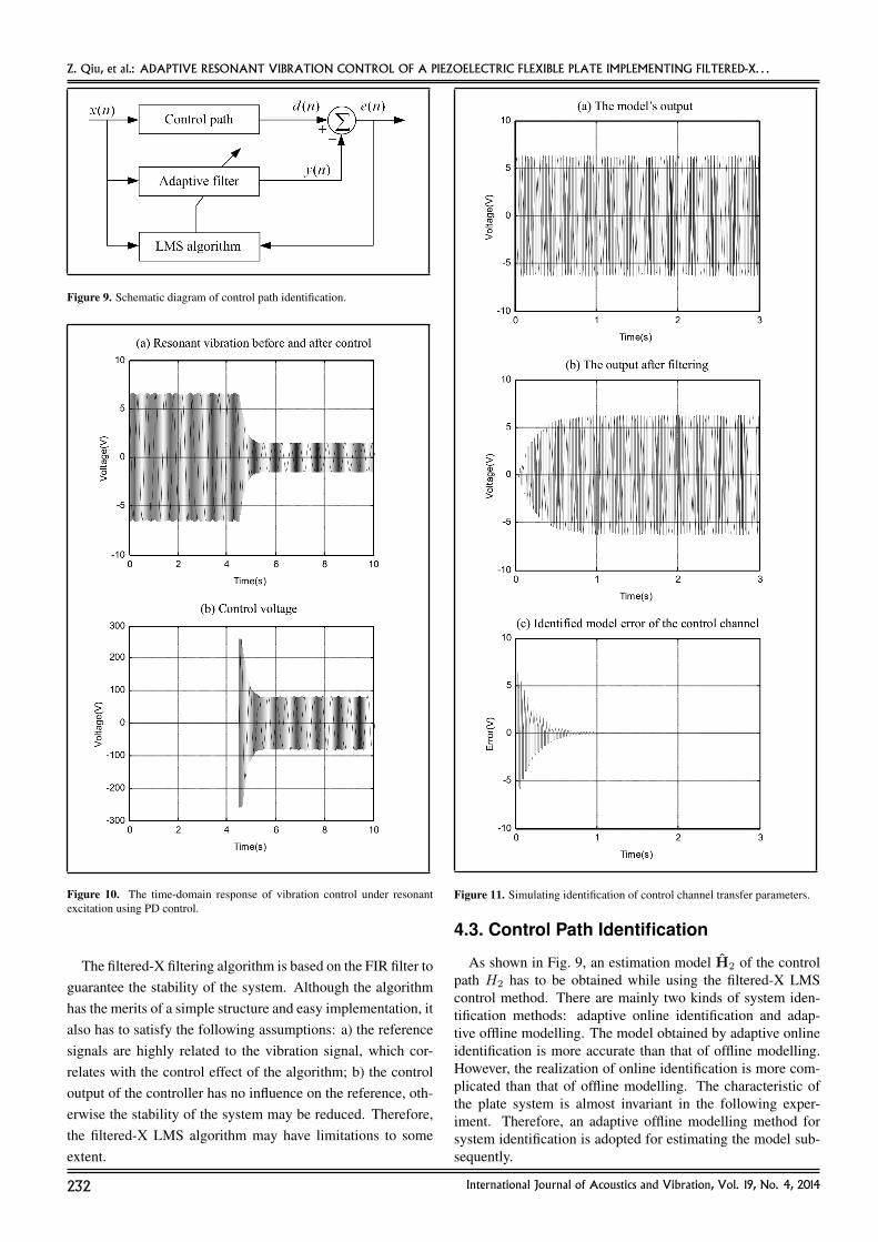
Figure 9. Schematic diagram of control path identification.
Figure 10. The time-domain response of vibration control under resonantexcitation using PD control.
The filtered-X filtering algorithm is based on the FIR filter toguarantee the stability of the system. Although the algorithmhas the merits of a simple structure and easy implementation, italso has to satisfy the following assumptions: a) the referencesignals are highly related to the vibration signal, which cor-relates with the control effect of the algorithm; b) the controloutput of the controller has no influence on the reference, oth-erwise the stability of the system may be reduced. Therefore,the filtered-X LMS algorithm may have limitations to someextent.
Figure 11. Simulating identification of control channel transfer parameters.
4.3. Control Path Identification
As shown in Fig. 9, an estimation model H2 of the controlpath H2 has to be obtained while using the filtered-X LMScontrol method. There are mainly two kinds of system iden-tification methods: adaptive online identification and adap-tive offline modelling. The model obtained by adaptive onlineidentification is more accurate than that of offline modelling.However, the realization of online identification is more com-plicated than that of offline modelling. The characteristic ofthe plate system is almost invariant in the following exper-iment. Therefore, an adaptive offline modelling method forsystem identification is adopted for estimating the model sub-sequently.
232 International Journal of Acoustics and Vibration, Vol. 19, No. 4, 2014

Z. Qiu, et al.: ADAPTIVE RESONANT VIBRATION CONTROL OF A PIEZOELECTRIC FLEXIBLE PLATE IMPLEMENTING FILTERED-X. . .
Figure 12. The time-domain response of vibration control under resonant excitation using filtered-X LMS control.
The working principle of Fig. 9 can be explained as follow-ing: the system to be identified and the adaptive filter are ex-cited by the same input x(n). Then, one can get an error signalbetween the actual output and the filter’s output. The error sig-nal is used by the LMS algorithm to adjust the weights of thefilter. Then the control output of the filter gradually gets closerto the actual output of the system. As soon as the error signalapproaches zero, the filter’s output is almost the same as that ofthe actual output. At that time, the model of the adaptive filtercan be used as the estimation model of the identified system.
In the process of system identification, an adaptive FIR filteris defined as the estimation model of the control path. Accord-ingly, the adaptive FIR filter works on the basis of the LMS al-gorithm. During the identification process, the selection of the
FIR filter’s order is important. If the order is selected too low,the precision of the obtained model will be decreased. Other-wise, if the order selected is too high, phase difference betweenthe estimation model and the actual model will be very large.Thus, the stability of the closed-loop system will be affected.
4.4. Control Simulation
In this section, numerical simulation is carried out to evalu-ate the effectiveness of two algorithms. The first one is the PDcontroller, and the second one is adaptive feedforward controlalgorithm with an adaptive FIR controller based on the LMSalgorithm. The model obtained by using the finite elementmodelling method in Section 3.3 is used for simulation inves-
International Journal of Acoustics and Vibration, Vol. 19, No. 4, 2014 233

Z. Qiu, et al.: ADAPTIVE RESONANT VIBRATION CONTROL OF A PIEZOELECTRIC FLEXIBLE PLATE IMPLEMENTING FILTERED-X. . .
tigation. The excited signal actuated on the actuators is a sinu-soidal signal with the frequency of 25.9 Hz and the amplitudeof 4 V. The control gains of the applied PD control algorithmare specified as Kp = 1.0, Kd = 0.001. The control action isapplied at the moment of t = 4.5 s.
The time-domain responses of vibration suppression andcontrol voltage are shown in Fig. 10(a) and Fig. 10(b), respec-tively. As depicted in Fig. 10(a), the vibration amplitude atten-uates more than 70% after the active control is applied.
When using the filtered-X LMS control algorithm, the adap-tive FIR filter estimation model of the control path has to beobtained beforehand. The system identification is carried outby using the LMS algorithm. The sinusoidal signal is imple-mented in the control path of the model built by FEM, and thenan adaptive FIR filter estimation model can be eventually ob-tained. The order of the adaptive FIR filter is specified as 12.
Figure 11(a) and Fig. 11(b) are the model’s output and thefilter’s output, respectively. Figure 11(c) shows the identifiedmodel error of the control channel. It can be seen that the erroris almost equal to zero after one second. This means that theoutput of the adaptive filter is almost the same as that of themodel’s output. The estimation adaptive FIR filter model ofthe control path is obtained.
The estimation model of the control path in theFIR adaptive filter using in simulation is H2 =[0.2636 0.2404 0.1536 0.0261 −0.1082 −0.2139 −0.2630−0.2425 −0.1579 −0.0314 0.1034 0.2108].
The convergence factor used in the simulation is µ =0.00002. The order of the adaptive filter is specified as 12.Once the estimation model of the control path is obtained, thesimulation results of the filtered-X LMS control method areshown in Fig. 12.
Figure 12(a) depicts the time-domain resonant vibration re-sponse before and after control using the filtered-X LMS algo-rithm. Figure 12(b) shows the control voltage applied to thePZT actuators. The controller weights of the adaptive filter areshown in Figs. 12(c), 12(d), 12(e), and 12(f).
From Figs. 12(c)–12(f), it can be seen that the controllervoltage is small at first due to the initial small weights values.As time goes by, the weights are adjusted according to the ref-erence signal and the vibration signal. It can be seen that thecontrol voltage is gradually increasing, as shown in Fig. 12(b).The voltage is stable after 8 s, as shown in Fig. 12(b). Thevibration amplitude is almost suppressed to zero after 8 s, asshown in Fig. 12(a).
From the simulation results, one can conclude that thefiltered-X LMS algorithm can suppress the resonant vibrationeffectively. Although the PD controller attenuates the vibrationin a shorter time, the vibration no longer attenuates after 5.2 s,as shown in Fig. 10(a). Therefore, the filtered-X LMS algo-rithm shows a better performance in controlling the vibrationunder resonant excitation.
5. EXPERIMENTAL RESULTS
5.1. Experimental Set-upTo validate the feasibility and the performance of the op-
timal placement of sensors/actuators and the applied adap-tive feedforward control algorithms, an active vibration control
Figure 13. Photograph of the experimental setup.
system of a clamped-clamped flexible plate was developed ac-cording to the previous analyses. Experiments on the resonantvibration suppression of the piezoelectric flexible plate wereconducted.
The experimental setup mainly consisted of a piezoelectricflexible clamped-clamped plate, the resonant excitation sys-tem, and the measurement and the control system. The photo-graph of the clamped-clamped plate setup is shown in Fig. 13.The plate is made up of epoxy resin. The dimensions and ma-terial properties of the plate and piezoelectric patches are givenin Section 3.3.
A signal generator is used to generate sinusoidal signals.The measured signal of the PZT sensor is amplified by acharger amplifier (YE5850). One piezoelectric amplifier (PA-I) is used to amplify the output control voltages. The outputsignal after the D/A converter ranges from −5 V to +5 V, andafter amplifying, the driving voltage for the control actuatorranges from −260 V to +260 V. The other piezoelectric am-plifier (PA-II) is used to amplify the generated signal by thegenerator in order to excite the resonant vibration of the plate.It can amplify the excitation sinusoidal signal (from −5 V to+5 V) to a high voltage (from −130 V to +130 V). An ARMboard and a personal computer (PC) are used as the signal pro-cessing and the control system with the corresponding A/D(analog to digital) and D/A (digital to analog) peripheral ex-pander circuit. The control code is written in C++ language.The sampling interval is chosen as 3 ms.
5.2. Experimental Identification and FiltersDesign
Since there are many factors such as the unknown physicalproperties of epoxy resin material, the modal frequencies ofthe system have to be identified. A swept sine (chirp) signalis generated by the signal generator. The starting frequency is0.5 Hz, and the stop frequency is 50 Hz. The swept time is50 s.
Figure 14(a) shows the excited swept sinusoidal signal andthe time-domain response signal measured by the PZT sen-sor when excited by PZT excitation actuators by amplifyingthe swept signal using the piezoelectric amplifier (PA-II). Fig-ure 14(b) depicts the frequency response of the plate by usingFFT for the time domain signal plotted in Fig. 14(a). FromFig. 14(b), it can be known that the first modal frequency ofthe plate is 21.6 Hz.
234 International Journal of Acoustics and Vibration, Vol. 19, No. 4, 2014

Z. Qiu, et al.: ADAPTIVE RESONANT VIBRATION CONTROL OF A PIEZOELECTRIC FLEXIBLE PLATE IMPLEMENTING FILTERED-X. . .
Figure 14. Measured swept sine vibration response excited by PZT actuators.
The natural frequency of the first mode obtained from theFEM model is 25.9 Hz; while in the experiments, the iden-tified modal frequency is 21.6 Hz. The possible reasonswhich may lead to the difference of modal frequencies be-tween the calculated and the experimental are listed as follow:(a) The clamped-clamped boundary condition in the simula-tion is ideal; while in the experiments, the boundaries may notbe totally clamped. (b) The physical parameters of the flexibleplate cannot be known accurately, such as the material density,Young’s modulus, uniformity, etc. These parameters used inthe simulation are not precisely consistent with those of theflexible plate used in the experimental material perfectly. Thisfactor may also lead to the difference between the two modalfrequencies. (c) Moreover, the mass of the glue and the con-nected signal wires of the PZT patches are not considered inthe calculation. These factors will decrease the modal fre-quency in the experimental system. Since the calculated modalfrequency is used to get an approximate value in order to ver-ify the feasibility of the control algorithms, the difference ofmodal frequencies between the calculated and the experimen-tal can be acceptable for this verification.
When the vibration of the first mode of the clamped-
clamped plate is excited, some harmonic frequency compo-nents are easily excited. High-frequency noise also exists inthe measured signal. Those harmonic frequency componentsand high-frequency noises will affect the control performanceof the experiments and sometimes even make the system unsta-ble. Therefore, the actual vibration signal should be processedby predefined filters before conducting active vibration controlexperiments.
In the experiments, Chebyshev filters are designed toprocess the measured vibration signal by the PZT sensor.The Chebyshev filter attenuates fast in the transitional zone.Though amplitude fluctuates in its passband, the Chebyshevfilter has the minimum error with an ideal filter frequency re-sponse curve. There are two kinds of Chebyshev filters. Oneis named the Type I Chebyshev filter, with a ripple in the pass-band; the other is the Type II Chebyshev filter, with a ripple inthe stopband.
The Type I Chebyshev filter is used here. Since only thevibration of the first mode is considered, a fourth order Cheby-shev band-pass filter is designed for signal processing. Thecentral frequency is equal to the first modal frequency of21.6 Hz. The bandwidth of the passband is set as 30 rad/s.The ripple of the passband is less than 1 dB.
5.3. Experiments on Resonant VibrationSuppression using PD Control
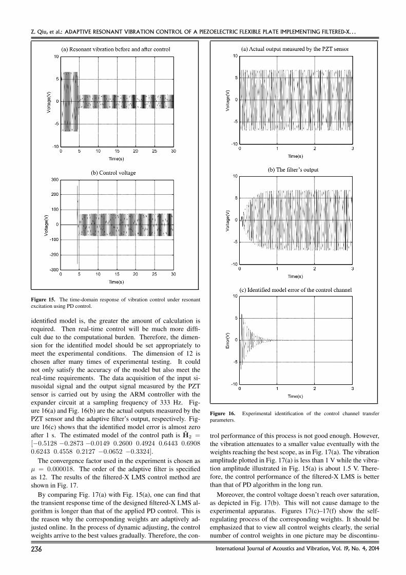
The sinusoidal signal is generated by a signal generator.Its amplitude and frequency are 4 V and 21.6 Hz, respec-tively. The frequency is the same as that of the first vibra-tion mode. The time-domain response of vibration suppres-sion under resonant excitation is shown in Fig. 15(a), using PDcontrol. Figure 15(b) shows the control voltage. The propor-tional and derivative control gains are specified as Kp = 0.95,Kd = 0.001, respectively
It can be seen from Fig. 15(b) that once the control actionis applied, the control voltage reaches saturation abruptly. Thelarge amplitude vibration is suppressed to a small amplitudevibration in Fig. 15(a) quickly, and the control voltage is de-creased due to the fact that the control value under the PD con-trol is equal to the sum of the vibration signal and its derivativeby multiplying the corresponding control gains.
From Fig. 15(a), it can be seen that the vibration amplitudeis constant after 8 s. The amplitude of the control voltage willnot change after 8 s, as shown in Fig. 15(b). The experimentalresults demonstrate the effectiveness of the PD controller. ThePD control experiment results are in good accordance with thesimulation results to some degree.
5.4. Experiments on Resonant VibrationSuppression using Filtered-X LMSAlgorithm
Similar to the simulation research, an offline identificationof the control path between the actuator and the sensor isperformed. The dimension for the identified model on theexperiment is set as 12. It is required that the dimensionof the identified model should describe the characteristics ofthe system accurately. Generally, the dimension should beset as small as possible provided that it could meet the con-trol requirements. Because the higher the dimension of the
International Journal of Acoustics and Vibration, Vol. 19, No. 4, 2014 235
Z. Qiu, et al.: ADAPTIVE RESONANT VIBRATION CONTROL OF A PIEZOELECTRIC FLEXIBLE PLATE IMPLEMENTING FILTERED-X. . .
Figure 15. The time-domain response of vibration control under resonantexcitation using PD control.
identified model is, the greater the amount of calculation isrequired. Then real-time control will be much more diffi-cult due to the computational burden. Therefore, the dimen-sion for the identified model should be set appropriately tomeet the experimental conditions. The dimension of 12 ischosen after many times of experimental testing. It couldnot only satisfy the accuracy of the model but also meet thereal-time requirements. The data acquisition of the input si-nusoidal signal and the output signal measured by the PZTsensor is carried out by using the ARM controller with theexpander circuit at a sampling frequency of 333 Hz. Fig-ure 16(a) and Fig. 16(b) are the actual outputs measured by thePZT sensor and the adaptive filter’s output, respectively. Fig-ure 16(c) shows that the identified model error is almost zeroafter 1 s. The estimated model of the control path is H2 =[−0.5128 −0.2873 −0.0149 0.2600 0.4924 0.6443 0.69080.6243 0.4558 0.2127 −0.0652 −0.3324].
The convergence factor used in the experiment is chosen asµ = 0.000018. The order of the adaptive filter is specifiedas 12. The results of the filtered-X LMS control method areshown in Fig. 17.
By comparing Fig. 17(a) with Fig. 15(a), one can find thatthe transient response time of the designed filtered-X LMS al-gorithm is longer than that of the applied PD control. This isthe reason why the corresponding weights are adaptively ad-justed online. In the process of dynamic adjusting, the controlweights arrive to the best values gradually. Therefore, the con-
Figure 16. Experimental identification of the control channel transferparameters.
trol performance of this process is not good enough. However,the vibration attenuates to a smaller value eventually with theweights reaching the best scope, as in Fig. 17(a). The vibrationamplitude plotted in Fig. 17(a) is less than 1 V while the vibra-tion amplitude illustrated in Fig. 15(a) is about 1.5 V. There-fore, the control performance of the filtered-X LMS is betterthan that of PD algorithm in the long run.
Moreover, the control voltage doesn’t reach over saturation,as depicted in Fig. 17(b). This will not cause damage to theexperimental apparatus. Figures 17(c)–17(f) show the self-regulating process of the corresponding weights. It should beemphasized that to view all control weights clearly, the serialnumber of control weights in one picture may be discontinu-
236 International Journal of Acoustics and Vibration, Vol. 19, No. 4, 2014

Z. Qiu, et al.: ADAPTIVE RESONANT VIBRATION CONTROL OF A PIEZOELECTRIC FLEXIBLE PLATE IMPLEMENTING FILTERED-X. . .
Figure 17. The time-domain response of vibration control under resonant excitation using filtered-X LMS control.
ous. The control voltage in Fig. 17(b) is tuned according to thecontroller weights, while the controller weights in Figs. 17(c),17(d), 17(e), and 17(f) are adjusted according to the referencesignal and the vibration signal.
The actual vibration control result shown in Fig. 17(a) is notas good as that of the simulation in Fig. 12(a). Actually, theexperimental phenomenon plotted in Fig. 17(a) is caused dueto the inconformity between the physical control path and theidentified control path. Gain error and phase error exist be-tween the physical control path and the identified control path.Gain error can be neglected by adjusting gain of the controlpath, while the phase error cannot be diminished. The phaseerror is first transmitted to the filtered-X signal according toEq. (14), and then it is transmitted to the control weights. The
phase errors are accumulated to the control output.The resonant vibration can still be attenuated to a very small
value due to the robustness to uncertainties of filtered-X LMSalgorithm. From Fig. 17(a), one can see that the vibrationreaches the dynamic balance after several times of adjust-ment. The vibration amplitude alternates from a little largerto even smaller. When the vibration amplitude gets bigger inFig. 17(a), the controller weights are tuned online according tothe current sensor signal and the latest reference signal, thusthe control voltage becomes larger.
The control performance of the filtered-X LMS algorithm isrelated with the selections of the convergence factor µ, the di-mension for the identified model of the control path, and theorder of adaptive filter. The value of µ is based on the autocor-
International Journal of Acoustics and Vibration, Vol. 19, No. 4, 2014 237

Z. Qiu, et al.: ADAPTIVE RESONANT VIBRATION CONTROL OF A PIEZOELECTRIC FLEXIBLE PLATE IMPLEMENTING FILTERED-X. . .
relation matrix eigenvalue of the input signal. The convergenceand convergence rate of the filtered-X LMS algorithm shouldbe guaranteed. The value range of µ should meet the inequal-ity: 0 < µ < 1/λmax. Actually, the optimal value can beselected through experimental tests. The larger value of µ willlead to a faster convergence rate. However, a value of µ thatis too large should not be chosen in order to avoid divergencein the control process. The dimension for the identified modelof the control path and the order of the adaptive filter will alsoaffect the control performance. A higher dimension will leadto better performance. However, a larger amount of calcula-tions will also be necessary. Therefore, the dimension for theidentified model of the control path and the order of the adap-tive filter should be specified appropriately, considering boththe control performance and the real-time requirements.
From the experimental results, it can be concluded that theresonant vibration of the clamped-clamped plate can be sup-pressed effectively by using the PD controller and the filtered-X LMS feedforward controller. In addition, control over satu-ration is prevented by using the filtered-X LMS control algo-rithm. Moreover, the control performance is also improved byusing the designed filter-X LMS algorithm.
6. CONCLUSIONS
This paper presents the numerical and experimental re-sults for resonant vibration control of a piezoelectric clamped-clamped plate excited by piezoelectric actuators. The dynam-ics model of the system is obtained by using the finite elementmethod. Locations of the PZT sensors and actuators are opti-mized by optimal placement criteria and GA search methods.A fourth order Chebyshev band-pass filter is designed to elim-inate the noises from the vibration signal measured by the PZTsensor. Numerical simulations and experiments are carried outto verify the effectiveness and feasibility of the optimal place-ment of piezoelectric sensors/actuators and the designed con-trol algorithms, including PD control and filtered-X LMS feed-forward control method. Simulation and experimental resultsdemonstrated that excited resonant vibration can be suppressedeffectively by the proposed two control methods and the loca-tion of sensors/actuators. Moreover, the filtered-X LMS al-gorithm shows better control performance in suppressing theresonant vibration.
FUNDING
This work was partially supported by the National Nat-ural Science Foundation of China under Grants 51175181and 60934001, and partially supported by the Fundamen-tal Research Funds for the Central Universities (SCUT,2014ZG0019), partially supported by National Laboratory ofSpace Intelligent Control. The authors gratefully acknowledgethese support agencies.
REFERENCES1 Niederberger, D., Morari, M., and Pietrzko, S. J. Adaptive
resonant shunted piezoelectric devices for vibration sup-pression, Proc. of SPIE Smart Structures and Materials,5056, 213–224, (2003).
2 Wu, S. Y., Turner, T. L., and Rizzi, S. A. Piezoelectric shuntvibration damping of an F-15 panel under high-acoustic ex-citation, SPIE’s 7th Annual International Symposium onSmart Structures and Materials, International Society forOptics and Photonics, 276–287, (2000).
3 Hyland, D., Junkins, J., and Longman, R. Active controltechnology for large space structures, Journal of Guidance,Control, and Dynamics, 16, 801–821, (1993).
4 Qiu, Z. C., Zhang, X. T., and Ye, C. D. Vibration suppres-sion of a flexible piezoelectric beam using BP neural net-work controller, Acta Mechanica Solida Sinica, 25, 417–428, (2012).
5 Moon, S. H. and Kim, S. J. Suppression of nonlinear com-posite panel flutter with active/passive hybrid piezoelectricnetworks using finite element method, Composite struc-tures, 59, 525–533, (2003).
6 Zhou, R., Lai, Z., Xue, D. Y., et al. Suppression of non-linear panel flutter with piezoelectric actuators using finiteelement method, AIAA Journal, 33, 1098–1105, (1995).
7 Forward, R. Electronic Damping of Orthogonal BendingModes in a Cylindrical Mast-Experiment, Journal of Space-craft and Rockets, 18 (1), 11–17, (1981).
8 Bailey, T. and Hubbard, J. Distributed piezoelectric-polymer active vibration control of a cantilever beam, Jour-nal of Guidance, Control, and Dynamics, 8 (5), 605–611,(1985).
9 Li, F.-M. Active aeroelastic flutter suppression of a super-sonic plate with piezoelectric material, International Jour-nal of Engineering Science, 51, 190–203, (2012).
10 Elshafei, M. A. and Alraiess, F. Modeling and analysis ofsmart piezoelectric beams using simple higher order sheardeformation theory, Smart Materials and Structures, 22,035006, (2013).
11 Farhadi, S. and Hosseini-Hashemi, S. Active vibration sup-pression of moderately thick rectangular plates, Journal ofVibration and Control, 17, 2040–2049, (2011).
12 Ramu, I. and Mohanty, S. Study on Free Vibration Anal-ysis of Rectangular Plate Structures Using Finite ElementMethod, Procedia Engineering, 38, 2758–2766, (2012).
13 Arbel, A. Controllability measures and actuator placementin oscillatory systems, International Journal of Control,33 (3), 565–574, (1981).
14 Bruant, I. and Proslier, L. Optimal location of actuators andsensors in active vibration control, Journal of intelligentmaterial systems and structures, 16 (3), 197–206, (2005).
15 Ambrosio, P., Resta, F., and Ripamonti, F. An H2 norm ap-proach for the actuator and sensor placement in vibrationcontrol of a smart structure, Smart Materials and Struc-tures, 21, 125016, (2012).
238 International Journal of Acoustics and Vibration, Vol. 19, No. 4, 2014

Z. Qiu, et al.: ADAPTIVE RESONANT VIBRATION CONTROL OF A PIEZOELECTRIC FLEXIBLE PLATE IMPLEMENTING FILTERED-X. . .
16 Nestorovic, T. and Trajkov, M. Optimal actuator and sensorplacement based on balanced reduced models, MechanicalSystems and Signal Processing, 36 (2), 271–289, (2013).
17 Qiu, Z. C., Zhang, X. M., Wu, H. X., et al. Optimal place-ment and active vibration control for piezoelectric smartflexible cantilever plate, Journal of Sound and Vibration,301, 521–543, (2007).
18 Darivandi, N., Morris, K., and Khajepour, A. An algo-rithm for LQ optimal actuator location, Smart Materialsand Structures, 22, 035001, (2013).
19 Bachmann, F., Bergamini, A. E., and Ermanni, P. Optimumpiezoelectric patch positioning: A strain energy–based fi-nite element approach, Journal of intelligent material sys-tems and structures, 23 (14), 1575–1591, (2012).
20 Bruant, I., Gallimard, L., and Nikoukar, S. Optimal piezo-electric actuator and sensor location for active vibrationcontrol, using genetic algorithm, Journal of Sound and Vi-bration, 329, 1615–1635, (2010).
21 Yang, Y., Jin, Z., and Kiong Soh, C. Integrated optimaldesign of vibration control system for smart beams usinggenetic algorithms, Journal of Sound and Vibration, 282,1293–1307, (2005).
22 Warminski, J., Bochenski, M., Jarzyna, W., et al. Activesuppression of nonlinear composite beam vibrations by se-lected control algorithms, Communications in NonlinearScience and Numerical Simulation, 16, 2237–2248, (2011).
23 Shin, C., Hong, C., and Jeong, W. B. Active vibration con-trol of beam structures using acceleration feedback controlwith piezoceramic actuators, Journal of Sound and Vibra-tion, 331, 1257–1269, (2012).
24 Lin, J. and Liu, W.-Z. Experimental evaluation of a piezo-electric vibration absorber using a simplified fuzzy con-troller in a cantilever beam, Journal of Sound and Vibration,296, 567–582, (2006).
25 Qiu, Z. C., Wu, H. X., and Zhang, D. Experimental re-searches on sliding mode active vibration control of flexiblepiezoelectric cantilever plate integrated gyroscope, Thin-Walled Structures, 47, 836–846, (2009).
26 Kun, L., Long-Xiang, C., and Guo-Ping, C. An Experimen-tal Study of Delayed Positive Feedback Control for a Flexi-ble Plate, International Journal of Acoustics and Vibration,17, 171–180, (2012).
27 Tong, Z., Long-Xiang, C. and Guo-Ping, C. Experimentalstudy of H∞ control for a flexible plate, Journal of Vibra-tion and Control, 18, 1631–1649, (2012).
28 Ji, H., Qiu, J., Badel, A., et al. Semi-active vibration con-trol of a composite beam by adaptive synchronized switch-ing on voltage sources based on LMS algorithm, Journalof intelligent material systems and structures, 20, 939–947,(2009).
29 Morgan, D. R. History, Applications, and Subsequent De-velopment of the FXLMS Algorithm [DSP History], SignalProcessing Magazine, IEEE, 30, 172–176, (2013).
30 Widrow, B. and Stearns, S. D. Adaptive Signal Processing,Prentice Hall, Englewood Cliffs, NJ, (1985).
31 Anderson, E. H. and How, J. P. Adaptive feedforward con-trol for actively isolated spacecraft platforms, AIAA Struc-tures, Structural Dynamics, and Materials Conference andExhibit, 7–10, (1997).
32 Zhu, X., Gao, Z., Huang, Q., et al. Analysis and imple-mentation of MIMO FULMS algorithm for active vibrationcontrol, Transactions of the Institute of Measurement andControl, 34 (7), 815–828, (2011).
33 Ma, K. Vibration control of smart structures with bondedPZT patches: novel adaptive filtering algorithm and hybridcontrol scheme, Smart Materials and Structures, 12 (3),473–482, (2003).
34 Carra, S., Amabili, M., Ohayon, R., et al. Active vibrationcontrol of a thin rectangular plate in air or in contact withwater in presence of tonal primary disturbance, AerospaceScience and Technology, 12 (1), 54–61, (2008).
35 Oh, J. E., Park, S. H., Hong, J. S., et al. Active vibrationcontrol of flexible cantilever beam using piezo actuator andFiltered-X LMS algorithm, KSME International Journal,12, 665–671, (1998).
36 Carnahan, J. J. and Richards, C. M. A modification tofiltered-X LMS control for airfoil vibration and flutter sup-pression, Journal of Vibration and Control, 14, 831–848,(2008).
37 Das, D. P., Moreau, D. J., and Cazzolato, B. S. A com-putationally efficient frequency-domain filtered-X LMS al-gorithm for virtual microphone, Mechanical Systems andSignal Processing, 37 (1–2), 440-454, (2013).
38 Huang, Q., Luo, J., Li, H., et al. Analysis and implemen-tation of a structural vibration control algorithm based onan IIR adaptive filter, Smart Materials and Structures, 22,085008, (2013).
39 Clark, R. L., Saunders, W. R., and Gibbs, G. P. Adap-tive structures: dynamics and control, Wiley, New York,(1998).
40 Holland, J. H. Adaption in Natural and Artificial Sys-tems. An Introductory Analysis with Applications to Bi-ology, Control, and Artificial Intelligence, University ofMichigan Press, Michigan, (1975).
41 Burgess, J. C. Active adaptive sound control in a duct: Acomputer simulation, The Journal of the Acoustical Societyof America, 70 (3), 715–726, (1981).
International Journal of Acoustics and Vibration, Vol. 19, No. 4, 2014 239