adaptive optics overview - science and technology ...€¦ · adaptive optics overview...
TRANSCRIPT

Adaptive OpticsOverview
(Astronomical)
Richard MyersDurham University
William Herschel Telescope with GLASRayleigh Laser Guide Star
Photo: Tibor Agocs, Isaac Newton Group of Telescopes

Outline• Generic Astronomical AO System
– Specifying AO for AtmosphericTurbulence Compensation
– and where this is not necessarily validfor more general applications
– Astronomical AO Components• 2nd generation Astronomical AO modes
– Wide field AO• Multi-Conjugate AO• Ground Layer AO• Laser Tomographic AO• Multi-object AO
– Very high order correction• eXtreme AO

3
Generic Astronomical Adaptive Optics
Telescope
Science
target
Laser
Natural
Guide
Star
Corrected
Science
focus
dichroic
beamsplitter
IR
light
Visible
light
Wave-
front
Sensor
Adaptive
Mirror
Control
System
wavefront
information
control
signals
atmospheric
turbulence
*
*
Uncorrectedimage
CorrectedImage
Uncorrectedwavefront
Correctedwavefront
Correcting the fluctuating aberrations caused by atmospheric turbulenceabove ground-basedoptical and near-infraredtelescopes.
Basic SingleConjugate AO system

• Kinetic energy in large scale turbulence cascades to smaller scales• Inertial interval
– Inner scale l0 - 1cm. Outer scale L0-10 to 100 m
• Refractive index Structure Function for separation r :
The AtmosphereKolmogorov model of turbulence
J. Vernin, Universite de Nice. Cerro Pachon for Gemini IGPO
[ ]2
2 2 / 3
( ( ) ( )
( )
n
n n
D r n r n
D r C r
! !) = + "
=

• Fried parameter r0 (∝λ6/5):– Size of aperture where
• Diffraction width = Seeing width– For infinite outer scale Kolmogorov turbulence in the near
field, r0 and the telescope diameter D are the only parametersrequired to:
• derive image profiles• determine the number of Deformable mirror actuators required to
produce a given residual wavefront phase variance (on average)~(spacing/r0)5/3
• Determine the required interactuator stroke• But Cn
2(h) will strongly affect off-axis performance• and Scintillation (amplitude variation) is often important in non-
astronomical AO - worst case: phase branch points• Thermal blooming
5 / 3
0
3/ 52top atm
2
00
2D phase structure function at telescope for plane waves:
6.88
2where 0.423 sec ( )
and is the zenith angle
n
rD
r
r C h dh
!
" #$
#
%
& '= ( )
* +
& '& '= ( )( )* +* +
,

Laser Applications of AO
Types of Adaptive Mirror(J.C.Dainty)

Continuous Facesheet Deformable Mirrors

Laser Applications of AO
Bimorph Mirror(J.C.Dainty, Imperial College)

Laser Applications of AO
BimorphDeformable Mirror

Laser Applications of AO
The ELECTRA Segmented Adaptive Mirror(76 tip-tilt-piston segments)
built by ThermoTrex, San Diego
228 degreeof freedomadaptivemirror

Laser Applications of AO
Fitting Error for ContinuousFacesheet Deformable
Mirror (and segmented)Flexible continuous phase sheet
reflectivesurface Actuators:
typically PZT or PMNthrow: 2-20 microns
Minimum physicalactuator separation ~ 7mm
Fitting error:σ2
f =κ (rs/r0)5/3 rad2
Lots of Astronomical assumptions!rs= projected actuator separation on sky κ = fitting coefficient for DM type. (continuous face sheet: 0.35-0.4)

Deformable Mirror Actuators1st generation DMs all involved piezoelectric (PZT) /
electrostrictive (PMN) actuators:– Serious Hysteresis (typically 5-40% of full range)– Curie Point (rapid change of level of hysteresis with temp)– Often limited stroke (hence stacked actuators)– Drive voltage (+/- 400V for low hysteresis “hard” PZT)
• OR magnetostrictive or voice call actuators for higherstroke applications– Non-linearity, bulk, power
• Newer DMs are available with electrostatic, magneticand electromagnetic actuators– Electrostatic
• low hysteresis• MEMS construction (300-500 micron spacing)• 4K actuator devices available• But non-linear, stroke still limited (4 -6 microns mechanical)
– Magnetic• Essentially no hysteresis• Low temperature operation• High stroke• 0.5V operation (COTS CMOS!)

Boston MicromachinesMEMS deformable mirror
Raw: 148 nm RMS WFE Flattened: 6-12 nm WFE In-band: 0.6 nm WFE
32x32 MEMS Evans et al 2006 Optics Exp. 14 5558
Electrostaticallyactuateddiaphragm
Attachmentpost
Membranemirror
GPICourtesy: Bruce Macintosh, LLNL

4k MEMS prototype
• 64x64 MEMS prototypes now in testing• 4 micron stroke Surface quality: 10-30 nm
RMS surface finish, 2-4 microns PV overallcurvature
4k MEMS prototypeCourtesy: Bruce Macintosh, LLNL

Parameter Value Comments
Clear aperture disk diameter 40 mm ± 5 mm Range of acceptable D is 30mmto 100mm (TBC)
If this specification cannot be met, please advice. Itmight be possible to accept a D between 30 mm and100 mm (TBC).Difference in x and y: overall slightly elliptical shapemight also be required.
Number of actuators across thediameter of the clear aperture disk
N=64N=84N=112
Regular Cartesian array assumed.
Yield 100% in mirror clear aperture for D as definedin DM19
Actuator Spacing D/(N-1) mm For D and N see DM19and DM20 respectively
Actuator Geometry Square Might want to investigate the feasibility of having adifferent spacing in the x and y directions.
Actuator Stroke (PV) Larger than or equal to 6 µm P to V mechanicalstroke
Not including provisions the manufacturer may takefor flattening the DM.
Inter-actuator Stroke ≥ 1.65 µm mechanical for N=64≥ 1.31 µm mechanical for N=84≥ 1.04 µm mechanical for N=112
High order WFE (wavefront error) ≤ 30 nm rms TBC after flattening (refer to thedefinition of “mirror flattening”)
Errors of spatial frequencies greater than thosecorresponding to half the actuator spacing frequency(i.e. errors which can not be self-corrected by theDM).
Surface Roughness ≤ 3 nm (TBC) rms
Scratch/Dig Ratio TBD
Temporal Frequency Response < 5° phase lag at frequencies = or < 500 Hz(TBC) and 10% of max stroke (phase lagdecreasing at lower frequencies)
Hysteresis ≤ 1% of maximum stroke (TBC) For max stroke.
In run actuator repeatability ≤ 6 nm RMS WFE over the entire clear apertureof the mirror when all the actuators arestimulated.
In-run repeatability implies the variation inperformance measured during a single power upusing the same actuator commands (within thedynamic range).

Run-to-run actuator repeatability ≤ 6 nm RMS WFE over the entire clear apertureof the mirror when all the actuators arestimulated.
Run-to-run actuator repeatability is the variation inmeasured performance across a number of devicepower-ups for the same actuator command set.
Reflectivity > 80% from 0.5µm to 0.6µm> 95% from 0.8µm to 1µm> 98% from 1.0µm to 2.5µm
These values should be treated as reflectanceguidelines. The supplier should comment onfeasibility.Durability specifications: any specified minimumreflectance should hold for a minimum TBC 10years in the indicated operational and storageenvironments.
Thermal Radiation When the DM actuators are operated, its opticalsurface temperature will not deviate fromambient temperature by more than 2%.

Laser Applications of AO
Shack-HartmannWavefront Sensor (WFS)
Microlens Array
Wavefront
Detector
Each xy offsetmeasures the local wavefrontslope across thecorrespondinglenslet.

Laser Applications of AO
CurvatureWavefront Sensor
Focal PlaneInput Wavefront
Sensing Planes

Wavefront Sensors andDetectors
• The curvature sensor minimises the number of pixelsrequired to remove a given wavefront variance (assumesKolmogorov or similar)– the use of noiseless fibre-coupled avalanche photo-diodes is
therefore feasible
• Shack-Hartmann requires more pixels so a CCD is normallyemployed– low read-noise multi-port frame-transfer specialised devices– Including on-chip electron-multiplication to effectively
eliminate read noise (multiplication noise effectively decreasesquantum efficiency, however)
• Much of the above is driven by photon starvation in NaturalGuide Star Astro AO– Where there is PLENTY of guide light one can consider other
detectors, especially CMOS.

Detector Quantum Efficiencyfor a CCD with a possiblechoice of dichroic filter

Laser Applications of AO
EEV CCD-39Projected read noise (e- rms) versus pixel
rate/port

Laser Applications of AO
4-port frame transfer CCD
Schematic of
4-port frame-
transfer
CCD
read-out port
shielded frame-
transfer area
light sensitive area
(4 quadrants,
gaps exaggerated)
shift register
(2) charge
movement
(1) frame
transfer
Total pixels
LL CCID-11: 64x64
Loral: 64x64
EEV:80x80

Real-time Computer-RTC (please see poster)
• 1st generation astro AO systems used:– Single PC or RISC device for Real-time (though inevitably
accompanied by other housekeeping processors with typicallyshared memory)
– Multi-CPU– Multi-DSP (most common)
• C40 DSP very popular and still running! • TigerSHARC more recently
• 2nd/3rd generation RTCs incorporate FPGAs for some tasks(and high speed serial comms)
• Cell processor evaluated– Not as good as might be thought for this application
• Future systems (for Extremely Large Telescopes)– Evaluating large FPGAs– And GPUs - very promissing!

Isoplanatic angle, temporalvariation
• Angle over which wavefront distortions are essentially thesame:
83
32 5
2 5 / 3
0
22.91 sec ( )
nC h h dh
!" #$
%& '& '
= ( )( )* +* +,
– It is possible to perform a similar turbulence weighted integral oftransverse wind speed in order to derive an effective wind speedand approximate timescale of seeing
– note the importance of Cn2(h) in both cases.
– LIMITS FIELD OF VIEW OF CONVENTIONAL AO

Correcting two turbulence layers
Deformable mirror
Turbulence Layers
Credit: Rigaut, MCAO for Dummies
Works on axis: bothlayers corrected
Does not work off axis: higher layeruncorrected, lower layer overcorrected

2 Deformable mirrors
Conjugated to eachlayer
Turbulence Layers
Credit: Rigaut, MCAO for Dummies
Multiconjugate AO corrects both layers

Ground Layer AO
• Very large field ofview but only partialcorrection
• Use multiple LGS toisolate the ground-layer turbulence whichapplies to all lines ofsight
• Apply correction withsingle deformablemirror– Often implemented with
an adaptive telescopesecondary mirror
Astronomical AO 27
[Courtesy ESO]

Ground Layer AO with AdaptiveSecondary Deformable Mirrors
28
MMT; being built for LBT, VLT
Compare with“normal” size DM

Laser Tomography AO
• Small field of view andhigh-order correction
• Use multiple LGS toperform tomographyof the turbulentvolume
• Apply correction withsingle deformablemirror
• Overcomes LGS coneeffect
Astronomical AO 29
[Courtesy ESO]Being built for VLT

Multi Object AO• Large field of view and
high-order correction– But individual fields are small
• Use multiple LGS toperform tomography of theturbulent volume
• Then the wavefront can becorrected for eachindividual target direction,by applying correction withmultiple deformablemirrors – one for eachscience target
• Correction is ‘open-loop’ inthat the wavefront is notnulled within a control loop
Astronomical AO 30
[Courtesy ESO]Being studied for 42m E-ELT

Extreme AO (XAO)• Tiny field of view and very
high-order correction• Use single very bright NGS
to analyse wavefront alongsingle line of sight
• Block light from guide starand search for companions
• Apply correction with veryhigh order DM
• Some interesting newtechnologies– Very high order
deformable mirrors (4KMEMS)
– Spatially filtered WFS– Apodised pupil plane Lyot
Coronographs– Auxiliary focal plane and
calibration WFSing
Astronomical AO 31
[OSCA: built UCL, deployed: WHT ]
Specialist Extreme AO planetfinders being built for VLT(SPHERE) and Gemini (GPI)
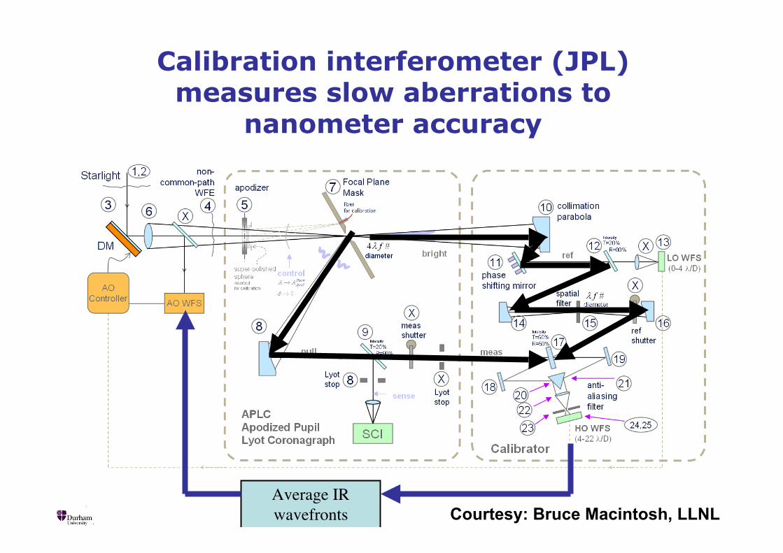
Calibration interferometer (JPL)measures slow aberrations to
nanometer accuracy
Average IRwavefronts Courtesy: Bruce Macintosh, LLNL