adaptive control of active magnetic bearing against
TRANSCRIPT
applied sciences
Article
Adaptive Control of Active Magnetic Bearing againstMilling Dynamics
Rong-Mao Lee * and Tsung-Chia Chen
Department of Mechanical Engineering, National Chin-Yi University of Technology, No. 57, Sec. 2,Zhongshan Rd., Taiping Dist., Taichung 41170, Taiwan; [email protected]* Correspondence: [email protected]; Tel.: +886-4-2392-4505 (ext. 7168)
Academic Editor: Chih Jer LinReceived: 27 November 2015; Accepted: 28 January 2016; Published: 15 February 2016
Abstract: For improving the defects in milling processes caused by traditional spindle bearings, e.g.,the dimensional discrepancy of a finished workpiece due to bearing wear or oil pollution by lubricant,a novel embedded cylindrical-array magnetic actuator (ECAMA) is designed for milling applications.Since ECAMA is a non-contact type actuator, a control strategy named fuzzy model-referenceadaptive control (FMRAC) is synthesized to account for the nonlinearities of milling dynamics andmagnetic force. In order to ensure the superior performance of spindle position regulation, theemployed models in FMRAC are all constructed by experiments. Based on the experimental results,the magnetic force by ECAMA is much stronger than that by the traditional active magnetic bearing(AMB) design under the same test conditions and identical overall size. The efficacy of ECAMAto suppress the spindle position deviation with the aid of FMRAC has been verified as well vianumerical simulations and practical metal cutting.
Keywords: active magnetic bearing; milling; adaptive control
1. Introduction
1.1. Active Magnetic Bearing (AMB)
Active magnetic bearing (AMB) is a magnetic actuator. In the past two decades, AMB hasbeen gradually adopted as a non-contact, lubrication-free, and levitation-efficient device in variousindustrial applications. Owing to its merits, such as the capability to regulate spindle dynamics,AMB has become a potential element for high-speed rotating machinery, e.g., milling machines [1–3],gas turbines [4,5], turbo-molecular pumps [6], and so on.
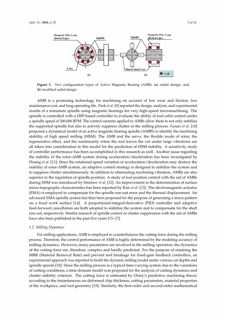
There are two common configurations of AMB, i.e., radial design and modified radial design, asshown in Figure 1 [7]. Radial design is also called the planar type because all of the EM (electromagnetic)poles are placed on the same cross-plane. Although the axial length of the radial design is relativelyshort, the coil turns wound on individual EM poles are very limited. Since the magnetic force isinduced by the coils, the force intensity of the radial design AMB is, therefore, restrained. To enhancethe magnetic force, the modified radial design was proposed [8]. The EM poles of each magnetic fluxloop in radial design (see the dotted line in Figure 1a) are re-arranged to make all the magnetic fluxpassing along the axial direction (see the dotted line in Figure 1b). Since the number of EM poles ineach cross-plane of the modified radial design is merely a half of that of the planar design, the interiorspace between adjacent poles is significantly increased so that more coil turns can be wound on eachyoke to increase the intensity of the magnetic force.
Appl. Sci. 2016, 6, 52; doi:10.3390/app6020052 www.mdpi.com/journal/applsci
Appl. Sci. 2016, 6, 52 2 of 16Appl. Sci. 2016, 6, 52 2 of 16
Figure 1. Two configuration types of Active Magnetic Bearing (AMB): (a) radial design, and (b) modified radial design.
AMB is a promising technology for machining on account of low wear and friction, low maintenance cost, and long operating life. Park et al. [9] reported the design, analysis, and experimental results of a miniature spindle using magnetic bearings for very high-speed micromachining. The spindle is controlled with a DSP-based controller to evaluate the ability of tool orbit control under a spindle speed of 200,000 RPM. The control currents applied to AMBs allow them to not only stabilize the supported spindle but also to actively suppress chatter in the milling process. Gourc et al. [10] proposed a dynamical model of an active magnetic bearing spindle (AMBS) to identify the machining stability of high speed milling (HSM). The AMB and the servo, the flexible mode of rotor, the regenerative effect, and the nonlinearity when the tool leaves the cut under large vibrations are all taken into consideration in this model for the prediction of HSM stability. A sensitivity study of controller performance has been accomplished in this research as well. Another issue regarding the stability of the rotor-AMB system during acceleration/deceleration has been investigated by Huang et al. [11]. Since the rotational speed variation or acceleration/deceleration may destroy the stability of rotor-AMB system, an adaptive control strategy is designed to stabilize the system and to suppress chatter simultaneously. In addition to eliminating machining vibration, AMBs are also superior in the regulation of spindle position. A study of tool position control with the aid of AMBs during HSM was introduced by Smirnov et al. [12]. An improvement in the determination of surface micro-topography characteristics has been reported by Kim et al. [13]. The electromagnetic actuator (EMA) is employed to compensate for the spindle run-out error and the thermal displacement. An advanced EMA-spindle system has then been proposed for the purpose of generating a micro-pattern on a fixed work surface [14]. A proportional-integral-derivative (PID) controller and adaptive feed-forward cancellation are both adopted to stabilize the system and to compensate for the shaft run-out, respectively. Similar research of spindle control or chatter suppression with the aid of AMBs have also been published in the past five years [15–17].
1.2. Milling Dynamics
For milling applications, AMB is employed to counterbalance the cutting force during the milling process. Therefore, the control performance of AMB is highly determined by the modeling accuracy of milling dynamics. However, many parameters are involved in the milling operation; the dynamics of the cutting force are, therefore, complex and hardly predicted. For the purpose of retaining the MRR (Material Removal Rate) and prevent tool breakage for fixed-gain feedback controllers, an experimental approach was reported to build the dynamic milling model under various cut depths and spindle speeds [18]. Since the milling process is a typical time-varying system due to the variations of cutting conditions, a time-domain model was proposed for the analysis of cutting dynamics and chatter stability criterion. The cutting force is estimated by Oxley’s predictive machining theory according to the instantaneous un-deformed chip thickness, cutting parameters, material properties of the workpiece, and tool geometry [19]. Similarly, the first-order and second-order mathematical models for milling dynamics were also proposed in 2002 and 2004,
Figure 1. Two configuration types of Active Magnetic Bearing (AMB): (a) radial design, and(b) modified radial design.
AMB is a promising technology for machining on account of low wear and friction, lowmaintenance cost, and long operating life. Park et al. [9] reported the design, analysis, and experimentalresults of a miniature spindle using magnetic bearings for very high-speed micromachining. Thespindle is controlled with a DSP-based controller to evaluate the ability of tool orbit control undera spindle speed of 200,000 RPM. The control currents applied to AMBs allow them to not only stabilizethe supported spindle but also to actively suppress chatter in the milling process. Gourc et al. [10]proposed a dynamical model of an active magnetic bearing spindle (AMBS) to identify the machiningstability of high speed milling (HSM). The AMB and the servo, the flexible mode of rotor, theregenerative effect, and the nonlinearity when the tool leaves the cut under large vibrations areall taken into consideration in this model for the prediction of HSM stability. A sensitivity studyof controller performance has been accomplished in this research as well. Another issue regardingthe stability of the rotor-AMB system during acceleration/deceleration has been investigated byHuang et al. [11]. Since the rotational speed variation or acceleration/deceleration may destroy thestability of rotor-AMB system, an adaptive control strategy is designed to stabilize the system andto suppress chatter simultaneously. In addition to eliminating machining vibration, AMBs are alsosuperior in the regulation of spindle position. A study of tool position control with the aid of AMBsduring HSM was introduced by Smirnov et al. [12]. An improvement in the determination of surfacemicro-topography characteristics has been reported by Kim et al. [13]. The electromagnetic actuator(EMA) is employed to compensate for the spindle run-out error and the thermal displacement. Anadvanced EMA-spindle system has then been proposed for the purpose of generating a micro-patternon a fixed work surface [14]. A proportional-integral-derivative (PID) controller and adaptivefeed-forward cancellation are both adopted to stabilize the system and to compensate for the shaftrun-out, respectively. Similar research of spindle control or chatter suppression with the aid of AMBshave also been published in the past five years [15–17].
1.2. Milling Dynamics
For milling applications, AMB is employed to counterbalance the cutting force during the millingprocess. Therefore, the control performance of AMB is highly determined by the modeling accuracy ofmilling dynamics. However, many parameters are involved in the milling operation; the dynamicsof the cutting force are, therefore, complex and hardly predicted. For the purpose of retaining theMRR (Material Removal Rate) and prevent tool breakage for fixed-gain feedback controllers, anexperimental approach was reported to build the dynamic milling model under various cut depths andspindle speeds [18]. Since the milling process is a typical time-varying system due to the variationsof cutting conditions, a time-domain model was proposed for the analysis of cutting dynamics andchatter stability criterion. The cutting force is estimated by Oxley’s predictive machining theoryaccording to the instantaneous un-deformed chip thickness, cutting parameters, material propertiesof the workpiece, and tool geometry [19]. Similarly, the first-order and second-order mathematical
Appl. Sci. 2016, 6, 52 3 of 16
models for milling dynamics were also proposed in 2002 and 2004, respectively [20,21]. A hybridadaptive control algorithm is employed to tune the feedrate to regulate the variation of cutting forcebased on the first-order milling dynamic model [20]. Another second-order model was synthesized ina self-tuning regulator for milling processes under various cut depths [21]. Due to the complexity ofmilling operations, neural network [22], fuzzy logic algorithms [23], and heuristic methods [24] wereall applied to the modeling of milling dynamics.
1.3. Embedded Cylindrical-Array Magnetic Actuator (ECAMA)
Though the two types of AMB designs shown in Figure 1 have ever been applied in computernumerical control (CNC) machines [1,3,6], the current AMB design still cannot meet the requirementsfor milling applications, such as the overall size of AMB and the force intensity [25–27]. Forthe purposes of solving these troublesome issues against milling applications, a novel embeddedcylindrical-array magnetic actuator (ECAMA) is proposed [28]. The configuration of the ECAMA isshown in Figure 2. It is composed of modified concave-type yokes [8] and I-shaped electromagnets.The I-shaped electromagnet consists of an I-shaped silicon steel core and the coil. Since the coil is nolonger wound on the yoke (please refer to Figure 1), the coil turns can be greatly increased. On theother hand, the overall size of the ECAMA in the radial direction can certainly be reduced. The topview of the ECAMA and spindle is shown in Figure 3. The yokes and the outer layer of spindle areall made of silicon steel to play the pathway of magnetic flux. The active magnetic milling moduleis depicted in Figure 4. The spindle position deviation is regulated by the magnetic force from theECAMA. In addition, a self-sensing module is equipped close to the cutter to measure the spindleposition deviation online.
Appl. Sci. 2016, 6, 52 3 of 16
respectively [20,21]. A hybrid adaptive control algorithm is employed to tune the feedrate to regulate the variation of cutting force based on the first-order milling dynamic model [20]. Another second-order model was synthesized in a self-tuning regulator for milling processes under various cut depths [21]. Due to the complexity of milling operations, neural network [22], fuzzy logic algorithms [23], and heuristic methods [24] were all applied to the modeling of milling dynamics.
1.3. Embedded Cylindrical-Array Magnetic Actuator (ECAMA)
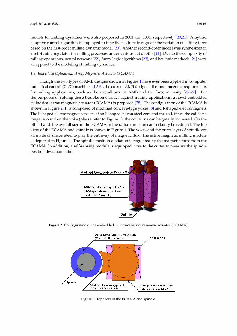
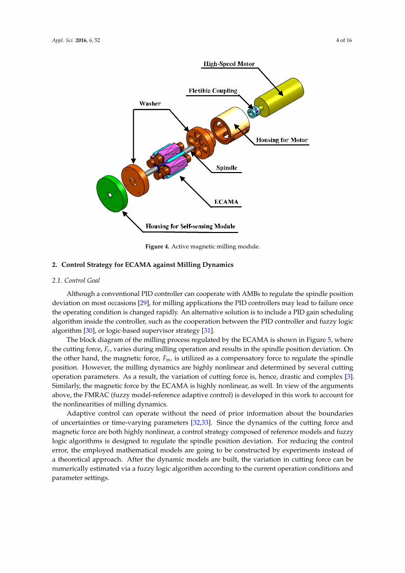
Though the two types of AMB designs shown in Figure 1 have ever been applied in computer numerical control (CNC) machines [1,3,6], the current AMB design still cannot meet the requirements for milling applications, such as the overall size of AMB and the force intensity [25–27]. For the purposes of solving these troublesome issues against milling applications, a novel embedded cylindrical-array magnetic actuator (ECAMA) is proposed [28]. The configuration of the ECAMA is shown in Figure 2. It is composed of modified concave-type yokes [8] and I-shaped electromagnets. The I-shaped electromagnet consists of an I-shaped silicon steel core and the coil. Since the coil is no longer wound on the yoke (please refer to Figure 1), the coil turns can be greatly increased. On the other hand, the overall size of the ECAMA in the radial direction can certainly be reduced. The top view of the ECAMA and spindle is shown in Figure 3. The yokes and the outer layer of spindle are all made of silicon steel to play the pathway of magnetic flux. The active magnetic milling module is depicted in Figure 4. The spindle position deviation is regulated by the magnetic force from the ECAMA. In addition, a self-sensing module is equipped close to the cutter to measure the spindle position deviation online.
Figure 2. Configuration of the embedded cylindrical-array magnetic actuator (ECAMA).
Figure 3. Top view of the ECAMA and spindle.
Figure 2. Configuration of the embedded cylindrical-array magnetic actuator (ECAMA).
Appl. Sci. 2016, 6, 52 3 of 16
respectively [20,21]. A hybrid adaptive control algorithm is employed to tune the feedrate to regulate the variation of cutting force based on the first-order milling dynamic model [20]. Another second-order model was synthesized in a self-tuning regulator for milling processes under various cut depths [21]. Due to the complexity of milling operations, neural network [22], fuzzy logic algorithms [23], and heuristic methods [24] were all applied to the modeling of milling dynamics.
1.3. Embedded Cylindrical-Array Magnetic Actuator (ECAMA)
Though the two types of AMB designs shown in Figure 1 have ever been applied in computer numerical control (CNC) machines [1,3,6], the current AMB design still cannot meet the requirements for milling applications, such as the overall size of AMB and the force intensity [25–27]. For the purposes of solving these troublesome issues against milling applications, a novel embedded cylindrical-array magnetic actuator (ECAMA) is proposed [28]. The configuration of the ECAMA is shown in Figure 2. It is composed of modified concave-type yokes [8] and I-shaped electromagnets. The I-shaped electromagnet consists of an I-shaped silicon steel core and the coil. Since the coil is no longer wound on the yoke (please refer to Figure 1), the coil turns can be greatly increased. On the other hand, the overall size of the ECAMA in the radial direction can certainly be reduced. The top view of the ECAMA and spindle is shown in Figure 3. The yokes and the outer layer of spindle are all made of silicon steel to play the pathway of magnetic flux. The active magnetic milling module is depicted in Figure 4. The spindle position deviation is regulated by the magnetic force from the ECAMA. In addition, a self-sensing module is equipped close to the cutter to measure the spindle position deviation online.
Figure 2. Configuration of the embedded cylindrical-array magnetic actuator (ECAMA).
Figure 3. Top view of the ECAMA and spindle. Figure 3. Top view of the ECAMA and spindle.
Appl. Sci. 2016, 6, 52 4 of 16Appl. Sci. 2016, 6, 52 4 of 16
Figure 4. Active magnetic milling module.
2. Control Strategy for ECAMA against Milling Dynamics
2.1. Control Goal
Although a conventional PID controller can cooperate with AMBs to regulate the spindle position deviation on most occasions [29], for milling applications the PID controllers may lead to failure once the operating condition is changed rapidly. An alternative solution is to include a PID gain scheduling algorithm inside the controller, such as the cooperation between the PID controller and fuzzy logic algorithm [30], or logic-based supervisor strategy [31].
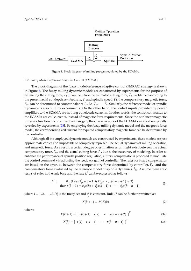
The block diagram of the milling process regulated by the ECAMA is shown in Figure 5, where the cutting force, cF , varies during milling operation and results in the spindle position deviation.
On the other hand, the magnetic force, mF , is utilized as a compensatory force to regulate the spindle position. However, the milling dynamics are highly nonlinear and determined by several cutting operation parameters. As a result, the variation of cutting force is, hence, drastic and complex [3]. Similarly, the magnetic force by the ECAMA is highly nonlinear, as well. In view of the arguments above, the FMRAC (fuzzy model-reference adaptive control) is developed in this work to account for the nonlinearities of milling dynamics.
Adaptive control can operate without the need of prior information about the boundaries of uncertainties or time-varying parameters [32,33]. Since the dynamics of the cutting force and magnetic force are both highly nonlinear, a control strategy composed of reference models and fuzzy logic algorithms is designed to regulate the spindle position deviation. For reducing the control error, the employed mathematical models are going to be constructed by experiments instead of a theoretical approach. After the dynamic models are built, the variation in cutting force can be numerically estimated via a fuzzy logic algorithm according to the current operation conditions and parameter settings.
Figure 4. Active magnetic milling module.
2. Control Strategy for ECAMA against Milling Dynamics
2.1. Control Goal
Although a conventional PID controller can cooperate with AMBs to regulate the spindle positiondeviation on most occasions [29], for milling applications the PID controllers may lead to failure oncethe operating condition is changed rapidly. An alternative solution is to include a PID gain schedulingalgorithm inside the controller, such as the cooperation between the PID controller and fuzzy logicalgorithm [30], or logic-based supervisor strategy [31].
The block diagram of the milling process regulated by the ECAMA is shown in Figure 5, wherethe cutting force, Fc, varies during milling operation and results in the spindle position deviation. Onthe other hand, the magnetic force, Fm, is utilized as a compensatory force to regulate the spindleposition. However, the milling dynamics are highly nonlinear and determined by several cuttingoperation parameters. As a result, the variation of cutting force is, hence, drastic and complex [3].Similarly, the magnetic force by the ECAMA is highly nonlinear, as well. In view of the argumentsabove, the FMRAC (fuzzy model-reference adaptive control) is developed in this work to account forthe nonlinearities of milling dynamics.
Adaptive control can operate without the need of prior information about the boundariesof uncertainties or time-varying parameters [32,33]. Since the dynamics of the cutting force andmagnetic force are both highly nonlinear, a control strategy composed of reference models and fuzzylogic algorithms is designed to regulate the spindle position deviation. For reducing the controlerror, the employed mathematical models are going to be constructed by experiments instead ofa theoretical approach. After the dynamic models are built, the variation in cutting force can benumerically estimated via a fuzzy logic algorithm according to the current operation conditions andparameter settings.
Appl. Sci. 2016, 6, 52 5 of 16Appl. Sci. 2016, 6, 52 5 of 16
Figure 5. Block diagram of milling process regulated by the ECAMA.
2.2. Fuzzy Model-Reference Adaptive Control (FMRAC)
The block diagram of the fuzzy model-reference adaptive control (FMRAC) strategy is shown in Figure 6. The fuzzy milling dynamic models are constructed by experiments for the purpose of estimating the cutting force, cF [3] online. Once the estimated cutting force, ,~
cF is obtained
according to the present axial cut depth, ,Ca feedrate, f , and spindle speed, ,Ω the
compensatory magnetic force, ,mF can be determined to counter-balance cF , i.e., cm FF~−= .
Similarly, the reference model of spindle dynamics is also built by experiments. On the other hand, the control inputs provided by power amplifiers to the ECAMA are nothing but electric currents. In other words, the control commands to the ECAMA are coil currents, instead of magnetic force requirements. Since the nonlinear magnetic force is a function of coil current and air gap, the characteristics of the ECAMA can also be explicitly revealed by experiments [28]. By employing the fuzzy milling dynamic model and the magnetic force model, the corresponding coil current for required compensatory magnetic force can be determined by the controller.
Although all the employed dynamic models are constructed by experiments, these models are just approximate copies and impossible to completely represent the actual dynamics of milling operation and magnetic force. As a result, a certain degree of estimation error might exist between the actual compensatory force, ,mF and the actual cutting force, ,cF due to the inaccuracy of modeling. In order to enhance the performance of spindle position regulation, a fuzzy compensator is proposed to modulate the control command via adjusting the feedback gain of controller. The rules for fuzzy compensator are based on the error, ,2e between the compensatory force
determined by controller, ,~mF and the compensatory force evaluated by the reference model of
spindle dynamics, mF . Assume there are terms of rules in the rule base and the rule iL can be expressed as follows:
)1()1()()1( then
is )1( , , is )1( , is )( if:
21
21
+−++−+=+
+−−
nkxakxakxakx
DnkxDkxDkxLin
ii
in
iii
(1)
where ,,,2,1 =i ijD is the fuzzy set and i
ja is constant. Rule iL can be further rewritten
as:
)()1( kXMkX i=+ (2)
where: TnkxkxkxkX ])2()()1([)1( +−+=+ (3a)
TnkxkxkxkX ])1()1()([)( +−−= (3b)
Figure 5. Block diagram of milling process regulated by the ECAMA.
2.2. Fuzzy Model-Reference Adaptive Control (FMRAC)
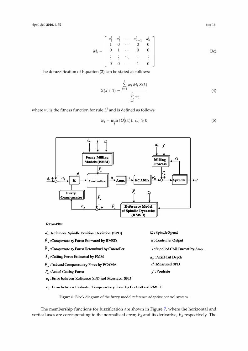
The block diagram of the fuzzy model-reference adaptive control (FMRAC) strategy is shownin Figure 6. The fuzzy milling dynamic models are constructed by experiments for the purpose ofestimating the cutting force, Fc [3] online. Once the estimated cutting force, rFc, is obtained according tothe present axial cut depth, aC, feedrate, f , and spindle speed, Ω, the compensatory magnetic force,Fm, can be determined to counter-balance Fc, i.e., Fm “ ´rFc. Similarly, the reference model of spindledynamics is also built by experiments. On the other hand, the control inputs provided by poweramplifiers to the ECAMA are nothing but electric currents. In other words, the control commands tothe ECAMA are coil currents, instead of magnetic force requirements. Since the nonlinear magneticforce is a function of coil current and air gap, the characteristics of the ECAMA can also be explicitlyrevealed by experiments [28]. By employing the fuzzy milling dynamic model and the magnetic forcemodel, the corresponding coil current for required compensatory magnetic force can be determined bythe controller.
Although all the employed dynamic models are constructed by experiments, these models are justapproximate copies and impossible to completely represent the actual dynamics of milling operationand magnetic force. As a result, a certain degree of estimation error might exist between the actualcompensatory force, Fm, and the actual cutting force, Fc, due to the inaccuracy of modeling. In order toenhance the performance of spindle position regulation, a fuzzy compensator is proposed to modulatethe control command via adjusting the feedback gain of controller. The rules for fuzzy compensatorare based on the error, e2, between the compensatory force determined by controller, rFm, and thecompensatory force evaluated by the reference model of spindle dynamics, Fm. Assume there are `
terms of rules in the rule base and the rule Li can be expressed as follows:
Li : if xpkq is Di1, xpk´ 1q is Di
2, ¨ ¨ ¨ , xpk´ n` 1q is Din
then xpk` 1q “ ai1xpkq ` ai
2xpk´ 1q ` ¨ ¨ ¨ ` ainxpk´ n` 1q
(1)
where i “ 1, 2, ¨ ¨ ¨ , `, Dij is the fuzzy set and ai
j is constant. Rule Li can be further rewritten as:
Xpk` 1q “ MiXpkq (2)
where:Xpk` 1q “ r xpk` 1q xpkq ¨ ¨ ¨ xpk´ n` 2q s
T(3a)
Xpkq “ r xpkq xpk´ 1q ¨ ¨ ¨ xpk´ n` 1q sT
(3b)
Appl. Sci. 2016, 6, 52 6 of 16
Mi “
»
—
—
—
—
—
—
–
ai1 ai
2 ¨ ¨ ¨ ain´1 ai
n1 0 ¨ ¨ ¨ 0 00 1 ¨ ¨ ¨ 0 0...
.... . .
......
0 0 ¨ ¨ ¨ 1 0
fi
ffi
ffi
ffi
ffi
ffi
ffi
fl
(3c)
The defuzzification of Equation (2) can be stated as follows:
Xpk` 1q “
ř
i“1wi Mi Xpkq
ř
i“1wi
(4)
where wi is the fitness function for rule Li and is defined as follows:
wi “ minjpDi
jpxqq, ωi ě 0 (5)
Appl. Sci. 2016, 6, 52 6 of 16
=
−
0100
00100001
121
in
in
ii
i
aaaa
M (3c)
The defuzzification of Equation (2) can be stated as follows:
)(
)1(
1i
1
=
==+
i
iii
w
kXMwkX (4)
where iw is the fitness function for rule iL and is defined as follows:
0)),((min ≥= iij
ji xDw ω (5)
Figure 6. Block diagram of the fuzzy model reference adaptive control system.
The membership functions for fuzzification are shown in Figure 7, where the horizontal and vertical axes are corresponding to the normalized error, 2E and its derivative, 2
•E respectively.
Figure 6. Block diagram of the fuzzy model reference adaptive control system.
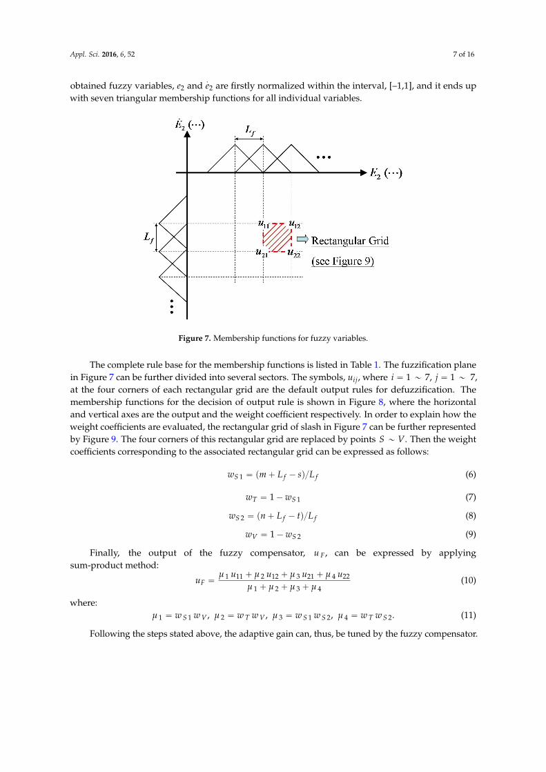
The membership functions for fuzzification are shown in Figure 7, where the horizontal andvertical axes are corresponding to the normalized error, E2 and its derivative, E2 respectively. The
Appl. Sci. 2016, 6, 52 7 of 16
obtained fuzzy variables, e2 and.e2 are firstly normalized within the interval, [–1,1], and it ends up
with seven triangular membership functions for all individual variables.
Appl. Sci. 2016, 6, 52 7 of 16
The obtained fuzzy variables, 2e and 2e are firstly normalized within the interval, [–1,1], and it ends up with seven triangular membership functions for all individual variables.
Figure 7. Membership functions for fuzzy variables.
The complete rule base for the membership functions is listed in Table 1. The fuzzification plane in Figure 7 can be further divided into several sectors. The symbols, ,iju where
,7~1,7~1 == ji at the four corners of each rectangular grid are the default output rules for defuzzification. The membership functions for the decision of output rule is shown in Figure 8, where the horizontal and vertical axes are the output and the weight coefficient respectively. In order to explain how the weight coefficients are evaluated, the rectangular grid of slash in Figure 7 can be further represented by Figure 9. The four corners of this rectangular grid are replaced by points VS ~ . Then the weight coefficients corresponding to the associated rectangular grid can be expressed as follows:
ffS LsLmw /)(1 −+= (6)
11 ST ww −= (7)
ffS LtLnw /)(2 −+= (8)
21 SV ww −= (9)
Finally, the output of the fuzzy compensator, ,Fu can be expressed by applying
sum-product method:
4321
224213122111
μμμμμμμμ
++++++
=uuuu
uF (10)
where:
.,,, 24213211 STSSVTVS wwwwwwww ==== μμμμ (11)
Following the steps stated above, the adaptive gain can, thus, be tuned by the fuzzy compensator.
Figure 7. Membership functions for fuzzy variables.
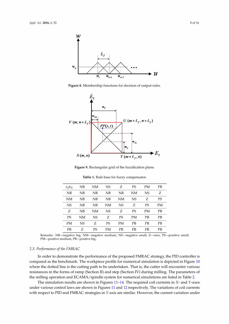
The complete rule base for the membership functions is listed in Table 1. The fuzzification planein Figure 7 can be further divided into several sectors. The symbols, uij, where i “ 1 „ 7, j “ 1 „ 7,at the four corners of each rectangular grid are the default output rules for defuzzification. Themembership functions for the decision of output rule is shown in Figure 8, where the horizontaland vertical axes are the output and the weight coefficient respectively. In order to explain how theweight coefficients are evaluated, the rectangular grid of slash in Figure 7 can be further representedby Figure 9. The four corners of this rectangular grid are replaced by points S „ V. Then the weightcoefficients corresponding to the associated rectangular grid can be expressed as follows:
wS 1 “ pm` L f ´ sqL f (6)
wT “ 1´wS 1 (7)
wS 2 “ pn` L f ´ tqL f (8)
wV “ 1´wS 2 (9)
Finally, the output of the fuzzy compensator, u F, can be expressed by applyingsum-product method:
uF “µ 1 u11 ` µ 2 u12 ` µ 3 u21 ` µ 4 u22
µ 1 ` µ 2 ` µ 3 ` µ 4(10)
where:µ 1 “ w S 1 w V , µ 2 “ w T w V , µ 3 “ w S 1 w S 2, µ 4 “ w T w S 2. (11)
Following the steps stated above, the adaptive gain can, thus, be tuned by the fuzzy compensator.
Appl. Sci. 2016, 6, 52 8 of 16Appl. Sci. 2016, 6, 52 8 of 16
Figure 8. Membership functions for decision of output rules.
Figure 9. Rectangular grid of the fuzzification plane.
Table 1. Rule base for fuzzy compensator.
2e /2e NB NM NS Z PS PM PB
NB NB NB NB NB NM NS Z NM NB NB NB NM NS Z PSNS NB NB NM NS Z PS PMZ NB NM NS Z PS PM PBPS NM NS Z PS PM PB PBPM NS Z PS PM PB PB PBPB Z PS PM PB PB PB PB
Remarks: NB—negative big, NM—negative medium, NS—negative small, Z—zero, PS—positive small, PM—positive medium, PB—positive big.
2.3. Performance of the FMRAC
In order to demonstrate the performance of the proposed FMRAC strategy, the PID controller is compared as the benchmark. The workpiece profile for numerical simulation is depicted in Figure 10 where the dotted line is the cutting path to be undertaken. That is, the cutter will encounter various resistances in the forms of ramp (Section II) and step (Section IV) during milling. The parameters of the milling operation and ECAMA/spindle system for numerical simulations are listed in Table 2.
The simulation results are shown in Figures 11–14. The required coil currents in X- and Y-axes under various control laws are shown in Figures 11 and 12, respectively. The variations of coil currents with respect to PID and FMRAC strategies in Y-axis are similar. However, the current
Figure 8. Membership functions for decision of output rules.
Appl. Sci. 2016, 6, 52 8 of 16
Figure 8. Membership functions for decision of output rules.
Figure 9. Rectangular grid of the fuzzification plane.
Table 1. Rule base for fuzzy compensator.
2e /2e NB NM NS Z PS PM PB
NB NB NB NB NB NM NS Z NM NB NB NB NM NS Z PSNS NB NB NM NS Z PS PMZ NB NM NS Z PS PM PBPS NM NS Z PS PM PB PBPM NS Z PS PM PB PB PBPB Z PS PM PB PB PB PB
Remarks: NB—negative big, NM—negative medium, NS—negative small, Z—zero, PS—positive small, PM—positive medium, PB—positive big.
2.3. Performance of the FMRAC
In order to demonstrate the performance of the proposed FMRAC strategy, the PID controller is compared as the benchmark. The workpiece profile for numerical simulation is depicted in Figure 10 where the dotted line is the cutting path to be undertaken. That is, the cutter will encounter various resistances in the forms of ramp (Section II) and step (Section IV) during milling. The parameters of the milling operation and ECAMA/spindle system for numerical simulations are listed in Table 2.
The simulation results are shown in Figures 11–14. The required coil currents in X- and Y-axes under various control laws are shown in Figures 11 and 12, respectively. The variations of coil currents with respect to PID and FMRAC strategies in Y-axis are similar. However, the current
Figure 9. Rectangular grid of the fuzzification plane.
Table 1. Rule base for fuzzy compensator.
.e2/e2 NB NM NS Z PS PM PB
NB NB NB NB NB NM NS Z
NM NB NB NB NM NS Z PS
NS NB NB NM NS Z PS PM
Z NB NM NS Z PS PM PB
PS NM NS Z PS PM PB PB
PM NS Z PS PM PB PB PB
PB Z PS PM PB PB PB PB
Remarks: NB—negative big, NM—negative medium, NS—negative small, Z—zero, PS—positive small,PM—positive medium, PB—positive big.
2.3. Performance of the FMRAC
In order to demonstrate the performance of the proposed FMRAC strategy, the PID controller iscompared as the benchmark. The workpiece profile for numerical simulation is depicted in Figure 10where the dotted line is the cutting path to be undertaken. That is, the cutter will encounter variousresistances in the forms of ramp (Section II) and step (Section IV) during milling. The parameters ofthe milling operation and ECAMA/spindle system for numerical simulations are listed in Table 2.
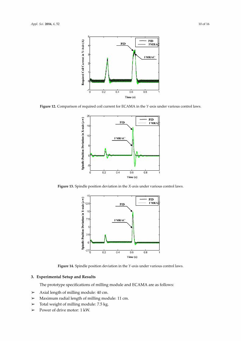
The simulation results are shown in Figures 11–14. The required coil currents in X- and Y-axesunder various control laws are shown in Figures 11 and 12 respectively. The variations of coil currentswith respect to PID and FMRAC strategies in Y-axis are similar. However, the current variation under

Appl. Sci. 2016, 6, 52 9 of 16
PID control in the feed direction (X-axis) is much more drastic in comparison with that under theFMRAC strategy. On the other hand, the maximum current under the FMRAC strategy is also lowerthan that under PID control especially during step resistance (referred to Section IV in Figure 10).The related spindle position deviation in X- and Y-axes are shown in Figures 13 and 14 respectively.Significant tremble of position deviation in X-axis can be observed under PID control, no matter ramp(Section II in Figure 10) or step (Section IV in Figure 10) cutting is engaged. In addition, the positiondeviations in Y-axis under both of the two control strategies are relatively smoother than those inX-axis due to the design of slot milling simulation. The proposed FMRAC strategy is verified bynumerical simulation for its efficacy of spindle position regulation. In comparison with PID control, theperformance of spindle position regulation under the proposed FMRAC strategy is much improvedand the required coil current is also reduced.
Table 2. Parameters of milling operation and ECAMA/spindle system for numerical simulations.
Parameters Value
Nominal air gap between spindle and yoke 10´3 mDistance between flexible coupling and top yoke 5ˆ 10´2 mDistance between flexible coupling and bottom yoke 0.2 mDistance between flexible coupling and gapself-sensing module 0.23 m
Distance between flexible coupling and cutter tip 0.25 mTransverse mass moment of inertia of spindle 2.2572ˆ 10´2 Kg´m2
Polar mass moment of inertia of spindle 5.9ˆ 10´4 Kg´m2
Stiffness of current 9.54 NAStiffness of displacement ´14313 NmSpinning speed of spindle 10k rpmFeedrate 3 mmin
Appl. Sci. 2016, 6, 52 9 of 16
variation under PID control in the feed direction (X-axis) is much more drastic in comparison with that under the FMRAC strategy. On the other hand, the maximum current under the FMRAC strategy is also lower than that under PID control especially during step resistance (referred to Section IV in Figure 10). The related spindle position deviation in X- and Y-axes are shown in Figures 13 and 14, respectively. Significant tremble of position deviation in X-axis can be observed under PID control, no matter ramp (Section II in Figure 10) or step (Section IV in Figure 10) cutting is engaged. In addition, the position deviations in Y-axis under both of the two control strategies are relatively smoother than those in X-axis due to the design of slot milling simulation. The proposed FMRAC strategy is verified by numerical simulation for its efficacy of spindle position regulation. In comparison with PID control, the performance of spindle position regulation under the proposed FMRAC strategy is much improved and the required coil current is also reduced.
Table 2. Parameters of milling operation and ECAMA/spindle system for numerical simulations.
Parameters Value Nominal air gap between spindle and yoke m10 3−
Distance between flexible coupling and top yoke m105 2−× Distance between flexible coupling and bottom yoke m2.0 Distance between flexible coupling and gap self-sensing module m23.0 Distance between flexible coupling and cutter tip m25.0 Transverse mass moment of inertia of spindle 22 mKg102572.2 −× −
Polar mass moment of inertia of spindle 24 mKg109.5 −× −
Stiffness of current N/A54.9 Stiffness of displacement N/m14313− Spinning speed of spindle 10k rpm Feedrate m/min3
Figure 10. Profile of workpiece for numerical simulation. Figure 10. Profile of workpiece for numerical simulation.
Appl. Sci. 2016, 6, 52 10 of 16
Figure 11. Comparison of required coil current for the ECAMA in the X-axis under various control laws.
Figure 12. Comparison of required coil current for ECAMA in the Y-axis under various control laws.
Figure 13. Spindle position deviation in the X-axis under various control laws.
Figure 11. Comparison of required coil current for the ECAMA in the X-axis under various control laws.
Appl. Sci. 2016, 6, 52 10 of 16
Appl. Sci. 2016, 6, 52 10 of 16
Figure 11. Comparison of required coil current for the ECAMA in the X-axis under various control laws.
Figure 12. Comparison of required coil current for ECAMA in the Y-axis under various control laws.
Figure 13. Spindle position deviation in the X-axis under various control laws.
Figure 12. Comparison of required coil current for ECAMA in the Y-axis under various control laws.
Appl. Sci. 2016, 6, 52 10 of 16
Figure 11. Comparison of required coil current for the ECAMA in the X-axis under various control laws.
Figure 12. Comparison of required coil current for ECAMA in the Y-axis under various control laws.
Figure 13. Spindle position deviation in the X-axis under various control laws. Figure 13. Spindle position deviation in the X-axis under various control laws.
Appl. Sci. 2016, 6, 52 11 of 16
Figure 14. Spindle position deviation in the Y-axis under various control laws.
3. Experimental Setup and Results
The prototype specifications of milling module and ECAMA are as follows:
Axial length of milling module: 40 cm. Maximum radial length of milling module: 11 cm. Total weight of milling module: 7.5 kg. Power of drive motor: 1 kW. Maximum speed of drive motor: 24k rpm Total weight of ECAMA: 2.8 kg Axial length of ECAMA: 12.2 cm Maximum radial length of ECAMA: 10 cm Maximum power consumption of ECAMA: 60 W (by an individual I-shape electromagnet)
The comparison between the ECAMA and traditional AMB is listed in Table 3. It is obvious that the ECAMA is able to provide a much stronger regulation force than that of a traditional design of similar size.
Table 3. Comparison between ECAMA and traditional AMB design.
Specifications ECAMA Modified Radial Design AMB Diameter (mm) 88 85
Axial Length (mm) 122 81
Coil Turns 1200 (on each individual I-shape silicon steel core)
220 (on each individual pair of electromagnetic poles)
Max Induced Magnetic Force (N)
224 (1.5 A coil current supplied)
65 (3 A coil current supplied)
Remark: The diameter of wound coil is 0.5 mm for both ECAMA and modified radial design AMB.
The test rig, including the milling machine (How-Mau CNC Machinery Co., Ltd., New Taipei City, Taiwan), is depicted in Figure 15. Commercial software MATLAB/Simulink (R2011a, The MathWorks, Natick, MA, USA, 2011) and signal processing interface (DS1104, dSPACE, Paderborn, Germany, 2007), have been also employed in the intensive experiments. A HSS (high-speed steel) cutter (Chien Wei Machinery&Hardware Co., Ltd., Taichung City, Taiwan) of 8 mm diameter and four cutting blades is equipped and the cutting path is defined in Figure 16. The operation parameters for milling test are set as follows:
Materials of workpiece: acrylic, aluminum and copper (three types of materials). Spindle speed (ω): 3000 rpm
Figure 14. Spindle position deviation in the Y-axis under various control laws.
3. Experimental Setup and Results
The prototype specifications of milling module and ECAMA are as follows:
â Axial length of milling module: 40 cm.â Maximum radial length of milling module: 11 cm.â Total weight of milling module: 7.5 kg.â Power of drive motor: 1 kW.

Appl. Sci. 2016, 6, 52 11 of 16
â Maximum speed of drive motor: 24k rpmâ Total weight of ECAMA: 2.8 kgâ Axial length of ECAMA: 12.2 cmâ Maximum radial length of ECAMA: 10 cmâ Maximum power consumption of ECAMA: 60 W (by an individual I-shape electromagnet)
The comparison between the ECAMA and traditional AMB is listed in Table 3. It is obvious thatthe ECAMA is able to provide a much stronger regulation force than that of a traditional design ofsimilar size.
Table 3. Comparison between ECAMA and traditional AMB design.
Specifications ECAMA Modified Radial Design AMB
Diameter (mm) 88 85
Axial Length (mm) 122 81
Coil Turns 1200 (on each individual I-shapesilicon steel core)
220 (on each individual pair ofelectromagnetic poles)
Max Induced Magnetic Force (N) 224(1.5 A coil current supplied)
65(3 A coil current supplied)
Remark: The diameter of wound coil is 0.5 mm for both ECAMA and modified radial design AMB.
The test rig, including the milling machine (How-Mau CNC Machinery Co., Ltd., New Taipei City,Taiwan), is depicted in Figure 15. Commercial software MATLAB/Simulink (R2011a, The MathWorks,Natick, MA, USA, 2011) and signal processing interface (DS1104, dSPACE, Paderborn, Germany, 2007),have been also employed in the intensive experiments. A HSS (high-speed steel) cutter (Chien WeiMachinery&Hardware Co., Ltd., Taichung City, Taiwan) of 8 mm diameter and four cutting blades isequipped and the cutting path is defined in Figure 16. The operation parameters for milling test are setas follows:
â Materials of workpiece: acrylic, aluminum and copper (three types of materials).â Spindle speed (ω): 3000 rpmâ Feedrate (f ): 300 mm/min.â Axial cut depth (Da): 2.5 mm.â Radial cut depth (Dr): 1 mm.
Appl. Sci. 2016, 6, 52 12 of 16
Feedrate (f): 300 mm/min. Axial cut depth (Da): 2.5 mm. Radial cut depth (Dr): 1 mm.
Figure 15. Test rig for milling operation.
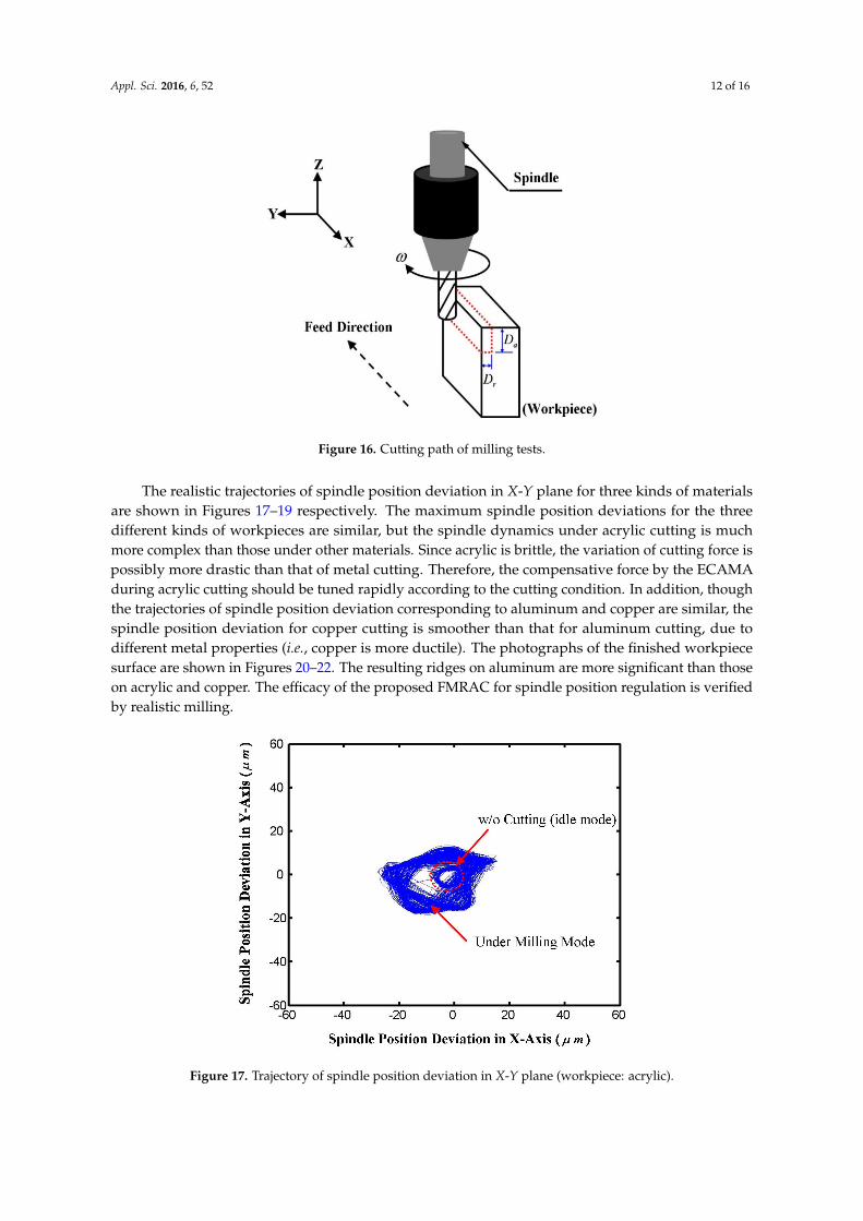
Figure 16. Cutting path of milling tests.
The realistic trajectories of spindle position deviation in X-Y plane for three kinds of materials are shown in Figures 17–19, respectively. The maximum spindle position deviations for the three different kinds of workpieces are similar, but the spindle dynamics under acrylic cutting is much more complex than those under other materials. Since acrylic is brittle, the variation of cutting force is possibly more drastic than that of metal cutting. Therefore, the compensative force by the ECAMA during acrylic cutting should be tuned rapidly according to the cutting condition. In addition, though the trajectories of spindle position deviation corresponding to aluminum and copper are similar, the spindle position deviation for copper cutting is smoother than that for aluminum cutting, due to different metal properties (i.e., copper is more ductile). The photographs of the finished workpiece surface are shown in Figures 20–22. The resulting ridges on aluminum are more significant than those on acrylic and copper. The efficacy of the proposed FMRAC for spindle position regulation is verified by realistic milling.
Figure 15. Test rig for milling operation.
Appl. Sci. 2016, 6, 52 12 of 16
Appl. Sci. 2016, 6, 52 12 of 16
Feedrate (f): 300 mm/min. Axial cut depth (Da): 2.5 mm. Radial cut depth (Dr): 1 mm.
Figure 15. Test rig for milling operation.
Figure 16. Cutting path of milling tests.
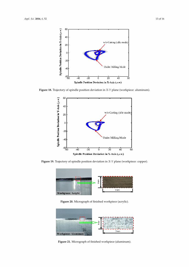
The realistic trajectories of spindle position deviation in X-Y plane for three kinds of materials are shown in Figures 17–19, respectively. The maximum spindle position deviations for the three different kinds of workpieces are similar, but the spindle dynamics under acrylic cutting is much more complex than those under other materials. Since acrylic is brittle, the variation of cutting force is possibly more drastic than that of metal cutting. Therefore, the compensative force by the ECAMA during acrylic cutting should be tuned rapidly according to the cutting condition. In addition, though the trajectories of spindle position deviation corresponding to aluminum and copper are similar, the spindle position deviation for copper cutting is smoother than that for aluminum cutting, due to different metal properties (i.e., copper is more ductile). The photographs of the finished workpiece surface are shown in Figures 20–22. The resulting ridges on aluminum are more significant than those on acrylic and copper. The efficacy of the proposed FMRAC for spindle position regulation is verified by realistic milling.
Figure 16. Cutting path of milling tests.
The realistic trajectories of spindle position deviation in X-Y plane for three kinds of materialsare shown in Figures 17–19 respectively. The maximum spindle position deviations for the threedifferent kinds of workpieces are similar, but the spindle dynamics under acrylic cutting is muchmore complex than those under other materials. Since acrylic is brittle, the variation of cutting force ispossibly more drastic than that of metal cutting. Therefore, the compensative force by the ECAMAduring acrylic cutting should be tuned rapidly according to the cutting condition. In addition, thoughthe trajectories of spindle position deviation corresponding to aluminum and copper are similar, thespindle position deviation for copper cutting is smoother than that for aluminum cutting, due todifferent metal properties (i.e., copper is more ductile). The photographs of the finished workpiecesurface are shown in Figures 20–22. The resulting ridges on aluminum are more significant than thoseon acrylic and copper. The efficacy of the proposed FMRAC for spindle position regulation is verifiedby realistic milling.
Appl. Sci. 2016, 6, 52 13 of 16
Figure 17. Trajectory of spindle position deviation in X-Y plane (workpiece: acrylic).
Figure 18. Trajectory of spindle position deviation in X-Y plane (workpiece: aluminum).
Figure 19. Trajectory of spindle position deviation in X-Y plane (workpiece: copper).
Figure 17. Trajectory of spindle position deviation in X-Y plane (workpiece: acrylic).
Appl. Sci. 2016, 6, 52 13 of 16
Appl. Sci. 2016, 6, 52 13 of 16
Figure 17. Trajectory of spindle position deviation in X-Y plane (workpiece: acrylic).
Figure 18. Trajectory of spindle position deviation in X-Y plane (workpiece: aluminum).
Figure 19. Trajectory of spindle position deviation in X-Y plane (workpiece: copper).
Figure 18. Trajectory of spindle position deviation in X-Y plane (workpiece: aluminum).
Appl. Sci. 2016, 6, 52 13 of 16
Figure 17. Trajectory of spindle position deviation in X-Y plane (workpiece: acrylic).
Figure 18. Trajectory of spindle position deviation in X-Y plane (workpiece: aluminum).
Figure 19. Trajectory of spindle position deviation in X-Y plane (workpiece: copper). Figure 19. Trajectory of spindle position deviation in X-Y plane (workpiece: copper).Appl. Sci. 2016, 6, 52 14 of 16
Figure 20. Micrograph of finished workpiece (acrylic).
Figure 21. Micrograph of finished workpiece (aluminum).
Figure 22. Micrograph of finished workpiece (copper).
4. Conclusions
In this work, the control strategy for the ECAMA to regulate spindle position deviation against milling dynamics has been proposed and verified. According to the simulation and experimental investigations, the following points are made:
(1) The ECAMA is a potential solution for milling applications of AMB. It is designed to deal with the issues of magnetic force intensity and overall AMB size at the same time. That is, the regulation force by AMB can be much enhanced under a reasonable size. However, for regular industrial machinery, the size of the ECAMA should be much larger than that in this work to achieve the requirements of industrial applications.
(2) Since the dynamics of milling processes and magnetic force are both highly nonlinear, estimation errors of the cutting force or magnetic force are definitely met. These force dynamics are investigated by experiments in this work instead of parameters analysis by theoretical methods. The accuracy of experimental models is highly determined by the experiment design. Therefore, the test rig design and the selection of analysis method should be addressed carefully.
(3) A fuzzy compensator is designed to achieve the adaptive gain control. As previously mentioned, the estimation errors are hard to be avoided. A fine-tuning scheme for control gain is, therefore, embedded to diminish the degree of estimation error. For further applications, such as chatter suppression, the membership functions and the decision rules have to be modified to make the regulation behavior faster and more efficient.
Author Contributions: R.-M. Lee conceived and designed the experiments; R.-M. Lee performed the experiments; R.-M. Lee and T.-C. Chen analyzed the data; T.-C. Chen contributed reagents/materials/analysis tools; R.-M. Lee wrote the paper.
Figure 20. Micrograph of finished workpiece (acrylic).
Appl. Sci. 2016, 6, 52 14 of 16
Figure 20. Micrograph of finished workpiece (acrylic).
Figure 21. Micrograph of finished workpiece (aluminum).
Figure 22. Micrograph of finished workpiece (copper).
4. Conclusions
In this work, the control strategy for the ECAMA to regulate spindle position deviation against milling dynamics has been proposed and verified. According to the simulation and experimental investigations, the following points are made:
(1) The ECAMA is a potential solution for milling applications of AMB. It is designed to deal with the issues of magnetic force intensity and overall AMB size at the same time. That is, the regulation force by AMB can be much enhanced under a reasonable size. However, for regular industrial machinery, the size of the ECAMA should be much larger than that in this work to achieve the requirements of industrial applications.
(2) Since the dynamics of milling processes and magnetic force are both highly nonlinear, estimation errors of the cutting force or magnetic force are definitely met. These force dynamics are investigated by experiments in this work instead of parameters analysis by theoretical methods. The accuracy of experimental models is highly determined by the experiment design. Therefore, the test rig design and the selection of analysis method should be addressed carefully.
(3) A fuzzy compensator is designed to achieve the adaptive gain control. As previously mentioned, the estimation errors are hard to be avoided. A fine-tuning scheme for control gain is, therefore, embedded to diminish the degree of estimation error. For further applications, such as chatter suppression, the membership functions and the decision rules have to be modified to make the regulation behavior faster and more efficient.
Author Contributions: R.-M. Lee conceived and designed the experiments; R.-M. Lee performed the experiments; R.-M. Lee and T.-C. Chen analyzed the data; T.-C. Chen contributed reagents/materials/analysis tools; R.-M. Lee wrote the paper.
Figure 21. Micrograph of finished workpiece (aluminum).

Appl. Sci. 2016, 6, 52 14 of 16
Appl. Sci. 2016, 6, 52 14 of 16
Figure 20. Micrograph of finished workpiece (acrylic).
Figure 21. Micrograph of finished workpiece (aluminum).
Figure 22. Micrograph of finished workpiece (copper).
4. Conclusions
In this work, the control strategy for the ECAMA to regulate spindle position deviation against milling dynamics has been proposed and verified. According to the simulation and experimental investigations, the following points are made:
(1) The ECAMA is a potential solution for milling applications of AMB. It is designed to deal with the issues of magnetic force intensity and overall AMB size at the same time. That is, the regulation force by AMB can be much enhanced under a reasonable size. However, for regular industrial machinery, the size of the ECAMA should be much larger than that in this work to achieve the requirements of industrial applications.
(2) Since the dynamics of milling processes and magnetic force are both highly nonlinear, estimation errors of the cutting force or magnetic force are definitely met. These force dynamics are investigated by experiments in this work instead of parameters analysis by theoretical methods. The accuracy of experimental models is highly determined by the experiment design. Therefore, the test rig design and the selection of analysis method should be addressed carefully.
(3) A fuzzy compensator is designed to achieve the adaptive gain control. As previously mentioned, the estimation errors are hard to be avoided. A fine-tuning scheme for control gain is, therefore, embedded to diminish the degree of estimation error. For further applications, such as chatter suppression, the membership functions and the decision rules have to be modified to make the regulation behavior faster and more efficient.
Author Contributions: R.-M. Lee conceived and designed the experiments; R.-M. Lee performed the experiments; R.-M. Lee and T.-C. Chen analyzed the data; T.-C. Chen contributed reagents/materials/analysis tools; R.-M. Lee wrote the paper.
Figure 22. Micrograph of finished workpiece (copper).
4. Conclusions
In this work, the control strategy for the ECAMA to regulate spindle position deviation againstmilling dynamics has been proposed and verified. According to the simulation and experimentalinvestigations, the following points are made:
(1) The ECAMA is a potential solution for milling applications of AMB. It is designed to deal with theissues of magnetic force intensity and overall AMB size at the same time. That is, the regulationforce by AMB can be much enhanced under a reasonable size. However, for regular industrialmachinery, the size of the ECAMA should be much larger than that in this work to achieve therequirements of industrial applications.
(2) Since the dynamics of milling processes and magnetic force are both highly nonlinear, estimationerrors of the cutting force or magnetic force are definitely met. These force dynamics areinvestigated by experiments in this work instead of parameters analysis by theoretical methods.The accuracy of experimental models is highly determined by the experiment design. Therefore,the test rig design and the selection of analysis method should be addressed carefully.
(3) A fuzzy compensator is designed to achieve the adaptive gain control. As previously mentioned,the estimation errors are hard to be avoided. A fine-tuning scheme for control gain is, therefore,embedded to diminish the degree of estimation error. For further applications, such as chattersuppression, the membership functions and the decision rules have to be modified to make theregulation behavior faster and more efficient.
Author Contributions: R.-M. Lee conceived and designed the experiments; R.-M. Lee performed the experiments;R.-M. Lee and T.-C. Chen analyzed the data; T.-C. Chen contributed reagents/materials/analysis tools; R.-M. Leewrote the paper.
Conflicts of Interest: The authors declare no conflicts of interest.
References
1. Kyung, J.H.; Lee, C.W. Controller design for a magnetically suspended milling spindle based on chatterstability analysis. Jpn. Soc. Mech. Eng. Ser. C 2003, 46, 416–422. [CrossRef]
2. Auchet, S.; Chevrier, P.; Lacour, M.; Lipinski, P. A new method of cutting force measurement based oncommand voltages of active electro-magnetic bearings. Int. J. Mach. Tools Manuf. 2004, 44, 1441–1449.[CrossRef]
3. Tsai, N.-C.; Shih, L.-W.; Lee, R.-M. Counterbalance of cutting force for advanced milling operations.Mech. Syst. Signal Process. 2010, 24, 1191–1208. [CrossRef]
4. Storace, A.F.; Sood, D.; Lyons, J.P.; Preston, M.A. Integration of magnetic bearings in the design of advancedgas turbine engines. J. Eng. Gas Turbines Power 1995, 117, 655–665. [CrossRef]
5. Swanson, E.E.; Heshmat, H.; Walton, II. Performance of a foil-magnetic hybrid bearing. J. Eng. GasTurbines Power 2002, 124, 375–382. [CrossRef]
6. Spirig, M.; Schmied, J.; Jenckel, P.; Kanne, U. Three practical examples of magnetic bearing control designusing a modern tool. J. Eng. Gas Turbines Power 2002, 124, 1025–1031. [CrossRef]
Appl. Sci. 2016, 6, 52 15 of 16
7. Imoberdorf, P.; Zwyssig, C.; Round, S.D.; Kolar, J.W. Combined radial-axial magnetic bearing for a 1 kW,500,000 rpm permanent magnet machine. In Proceedings of the 22nd Annual IEEE Applied Power ElectronicsConference, Anacheim, CA, USA, 25 February–1 March 2007.
8. Tsai, N.-C.; Hsu, S.-L. On sandwiched magnetic bearing design. Electromagnetics 2007, 27, 371–385. [CrossRef]9. Park, J.-K.; Kyung, J.-H.; Shin, W.-C.; Ro, S.-K. A magnetically suspended miniature spindle and its
application for tool orbit control. Int. J. Precis. Eng. Manuf. 2012, 13, 1601–1607. [CrossRef]10. Gourc, E.; Seguy, S.; Arnaud, L. Chatter milling modeling of active magnetic bearing spindle in high-speed
domain. Int. J. Mach. Tools Manuf. 2011, 51, 928–936. [CrossRef]11. Huang, T.; Chen, Z.; Zhang, H.-T.; Ding, H. Active control of an active magnetic bearings supported spindle
for chatter suppression in milling process. J. Dyn. Syst. Meas. Control 2015, 137, 111003–111011. [CrossRef]12. Smirnov, A.; Pesch, A.H.; Pyrhonen, O.; Sawicki, J.T. High-precision cutting tool tracking with a magnetic
bearing spindle. J. Dyn. Syst. Meas. Control 2015, 137. [CrossRef]13. Kim, J.H.; Zhao, S.; Kim, G.H.; Lee, S.-K. Rolling bearing-suspended spindle run-out control using repetitive
control and adaptive feedforward cancellation. Int. J. Precis. Eng. Manuf. 2013, 14, 2171–2178. [CrossRef]14. Kim, J.-H.; Lee, S.-K. Micro-patterning technique using a rotating cutting tool controlled by an
electromagnetic actuator. Int. J. Mach. Tools Manuf. 2016, 101, 52–64. [CrossRef]15. Qiao, X.; Zhu, C. The active vibration attenuation of a built-in motorized milling spindle. J. Vibrat. Control
2013, 19, 2434–2447. [CrossRef]16. Wroblewski, A.C.; Sawicki, J.T.; Pesch, A.H. Rotor model updating and validation for an active magnetic
bearing based high-speed machining spindle. J. Eng. Gas Turbines Power 2012, 134. [CrossRef]17. Sohnl, J.W.; Paengl, Y.-S.; Choil, S.-B. An active mount using an electromagnetic actuator for vibration control:
experimental investigation. J. Mech. Eng. Sci. 2010, 224, 1617–1625. [CrossRef]18. Lauderbaugh, L.K.; Ulsoy, A.G. Dynamic modeling for control of milling process. J. Eng. Ind. 1998, 110,
367–375. [CrossRef]19. Li, H.Z.; Li, X.P.; Chen, X.Q. A novel chatter stability criterion for the modeling and simulation of the
dynamic milling process in the time domain. Int. J. Adv. Manuf. Technol. 2003, 22, 619–625. [CrossRef]20. Yang, M.Y.; Lee, T.M. Hybrid adaptive control based on the characteristics of CNC end milling. Int. J. Mach.
Tools Manuf. 2002, 42, 489–499. [CrossRef]21. Peng, Y.H. On the performance enhancement of self-turning adaptive control for time varying machining
processes. Int. J. Adv. Manuf. Technol. 2004, 24, 395–403. [CrossRef]22. Chiang, S.-T.; Liu, D.-I.; Lee, A.; Chieng, W. Adaptive control optimization in end milling using neural
network. Int. J. Mach. Tools Manuf. 1995, 34, 637–660. [CrossRef]23. Kim, M.K.; Cho, M.W.; Kim, K. Application of the fuzzy control strategy to adaptive force control of
non-minimum phase end milling operations. Int. J. Mach. Tools Manuf. 1994, 33, 677–696. [CrossRef]24. Tarng, Y.S.; Hwang, S.T. Adaptive learning control of milling operations. Mechatronics 1995, 5, 937–948.
[CrossRef]25. Morita, N.; Yoshida, Y.; Kishioka, S.; Ueno, S. Study on high-speed milling of hard materials. Jpn. Soc. Mech.
Eng. Part C 1997, 63, 4347–4353. [CrossRef]26. Hegazi, A.S. Comparison between conventional and high speed milling processes. J. Eng. Appl. Sci. 2006, 53,
45–61.27. Tang, D.W.; Wang, C.Y.; Hu, Y.N. Finite-element simulation of conventional and high-speed peripheral
milling of hardened mold steel. Metall. Mater. Trans. A 2009, 40, 3245–3257. [CrossRef]28. Tsai, N.-C.; Lee, R.-M. Regulation of spindle position by magnetic actuator array. Int. J. Adv. Manuf. Technol.
2011, 53, 93–104. [CrossRef]29. Allaire, P.E.; Humphris, R.R.; Kelm, R.D. Dynamics of a digitally controlled magnetic bearing. Nippon Kikai
Gakkai Ronbunshu 1985, 51, 1095–1100.30. Rosyadi, M.; Muyeen, S.M.; Takahashi, R.; Tamura, J. A design fuzzy logic controller for a permanent magnet
wind generator to enhance the dynamic stability of wind farms. Appl. Sci. 2012, 2, 780–800. [CrossRef]31. Yeh, H.-Y.; Lee, C.-D. The logic-based supervisor control for sun-tracking system of 1 MW HCPV demo
plant: Study case. Appl. Sci. 2012, 2, 100–113. [CrossRef]

Appl. Sci. 2016, 6, 52 16 of 16
32. Sheng, S.; Sun, C. A near-hover adaptive attitude control strategy of a ducted fan micro aerial vehicle withactuator dynamics. Appl. Sci. 2015, 5, 666–681. [CrossRef]
33. Sheng, S.; Sun, C. Design of a stability augmentation system for an unmanned helicopter based on adaptivecontrol techniques. Appl. Sci. 2015, 5, 575–586. [CrossRef]
© 2016 by the authors; licensee MDPI, Basel, Switzerland. This article is an open accessarticle distributed under the terms and conditions of the Creative Commons by Attribution(CC-BY) license (http://creativecommons.org/licenses/by/4.0/).