*ad usaavlabs technical report 65-81 an … · a an investigation of propeller slipstream effects...
TRANSCRIPT
*AD
USAAVLABS TECHNICAL REPORT 65-81
a AN INVESTIGATION OF PROPELLER SLIPSTREAMEFFECTS ON V/STOL AIRCRAFTPERFORMANCE AND STABILITY
By
L. Butler
K. P. Huang
L. Goland
February 1966
U. S. ARMY AVIATION MATERIEL LABORATORIES
FORT EUSTIS, VIRGINIA
CONTRACT DA 44-177-AMC-48(T)
DYNASCIENCES CORPORATIONBLUE BELL. PENNSYLVANIA
Distribution of thisdocument is unlimited.

4Vf7
Disclaimers
The findings in this report are not to be construed as anofficial Department of the Army position, unless so desig-nated by other authorized documents.
When Government drawings, specifications, or other data areused for any purpose other than in connection with a defi-nitely related Government procurement operation, the UnitedStates Government thereby incurs no responsibility nor anyobligation whatsoever; and the fact that the Government mayhave formulated, furnished, or in any way supplied the saiddrawings, specifications, or other data is not to be regardedby implication or otherwi3e as in any manner licensing theholder or any other person or corporation, or conveying anyrights or permission, to manufacture, use, or sell any pat-ented invention that may in any way be related thereto.
Disposition Instructions
Destroy this report when it is no longer needed. Do notreturn it to the originator.
DEPARTMENT OF THE ARMYU S ARMY AVIATION MATERIEL LABORATORIES
FORT EUSTIS. VIRGINIA 23604
The study summarized in this report was undertaken to extendknowledge of performance and stability characteristics ofV/SIOL aircraft.
The report has been reviewed by the U. S. Army AviationMateriel Laboratories and is considered to be technicallysound. It is published for the exchange of information and
stimulation of ideas.
Task ID121401A14203Contract DA 44-177-AMC-48(T)
USAAVLABS Technical Report 65-81
February 1966
AN INVESTIGATION OF PROPELLER SLIPSTREAMEFFECTS ON V/STOL AIRCRAFT
PERFORMANCE AND STABILITY
Dynasciences Report No. DCR-174
byL. ButlerK.P. HuangL. Goland
Prepared by
Dynasciences CorporationBlue Bell, Pennsylvania
for
U. S. ARMY AVIATION MATERIEL LABORATORIESFORT EUSTIS, VIRGINIA
Di.tribution of thisdocument is unlimited.
An investigation was made of the effects ofpropeller slipstream on several aspects of V/STOL aircraftperformance and stability. Specific areas investigatedinclude wing stall during transition, minimum wing size forstall-free transition, and the effects of slipstream onaircraft pitching moments. In addition, a stability analysiswas performed, and analog .-rap1ter techniques were used todetermine the feasibility of utilizing the slipstream forstability augmentation. Finally, the effects of thenonuniformity of slipstream velocity and wing geometrymodifications on performance were analyzed.
iii
aa
FOREWORD
This report presents the results of the investiga-
tion made for the U.S. Army Aviation Materiel Laboratories*(USAAVLABS), Fort Eustis, Virginia, under Phases IV throughVI of Contract DA 44-177-AMC-48(T), during the period April1964 through March 1965.
The re:sults of L he work performed for the precedingphases :f the above mentionled contract are covered by TRECOMTechnical Report 64-47, publisheo a.n August 1964.
*Formrerly, U.S. Army Transportation Research Command
V
CONTENTS
Pýae
SU M ARY ................................ .. i
FOREWORD .................................... ........ v
LIST OF ILLUSTRATIONS ............................... viii
LIST OF SYMBOLS ..................................... xiii
INTRODUCTION ........................................ 1
STALL OF A WING IMMERSED IN PROPELLER SLIPSTREAM .... 3
MINIMUM WING SIZE FOR VTOL AIRCRAFT TRANSITION WITH-OUT STALL ........................................... 15
PROPELLER AND SLIPSTREAM-INDUCED MOMENTS ............. 25
SLIPSTREAM EFFECTS ON VTOL AIRCRAFT STABILITY ....... 51
MODIFICATION OF SLIPSTREAM TO AUGMENT LIJ- ANDCONTROL . . . . . . . . . . . . . . . . . ......... 96
THE EFFECT OF WING GEOMETRY ON LIFT .......... o...... 110
B IBLIOGRAPHY ........................................ 119
DISTRIBUTION ........................................ 123
vii

-.... . mm z .i - .i i -
I LLUSTRAT IONS
Figure Page
1 Velocity and Angle-of-Attack Distributionof Assumed Slipstream at the Wing .......... 5
2 Pstimated Spanwise Lift Coefficient Dis-tribution and Extent of Wing Stall (Pro-peller Rotating Down at Wing Tip, Aw = 15Degrees, CQ = 0.58, A = 5.00, NACA 0015Airfoil Section) ............................ 9
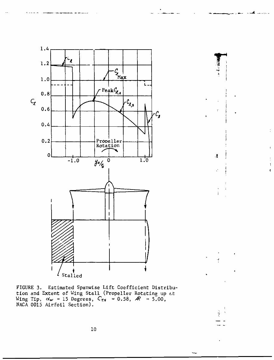
3 Estimated Spanwise Lift Coefficient Dis-tribution and Extent of Wing Stall (Pro-peller Rotating up at Wing Tip, 4 = 15Degrees, Cys = 0.58, A = 5.00, NACA0015 Airfoil Section) ...................... 10
4 Estimated Spanwise Lift Coefficient Dis-tribution and Extent of Wing Stall (Pro-peller Rotating Down at Wing Tip, Q = 50Degrees, CAs = 0.88, 4Z = 5.0, NACA 0015Airfoil Section) ....................... o... 12
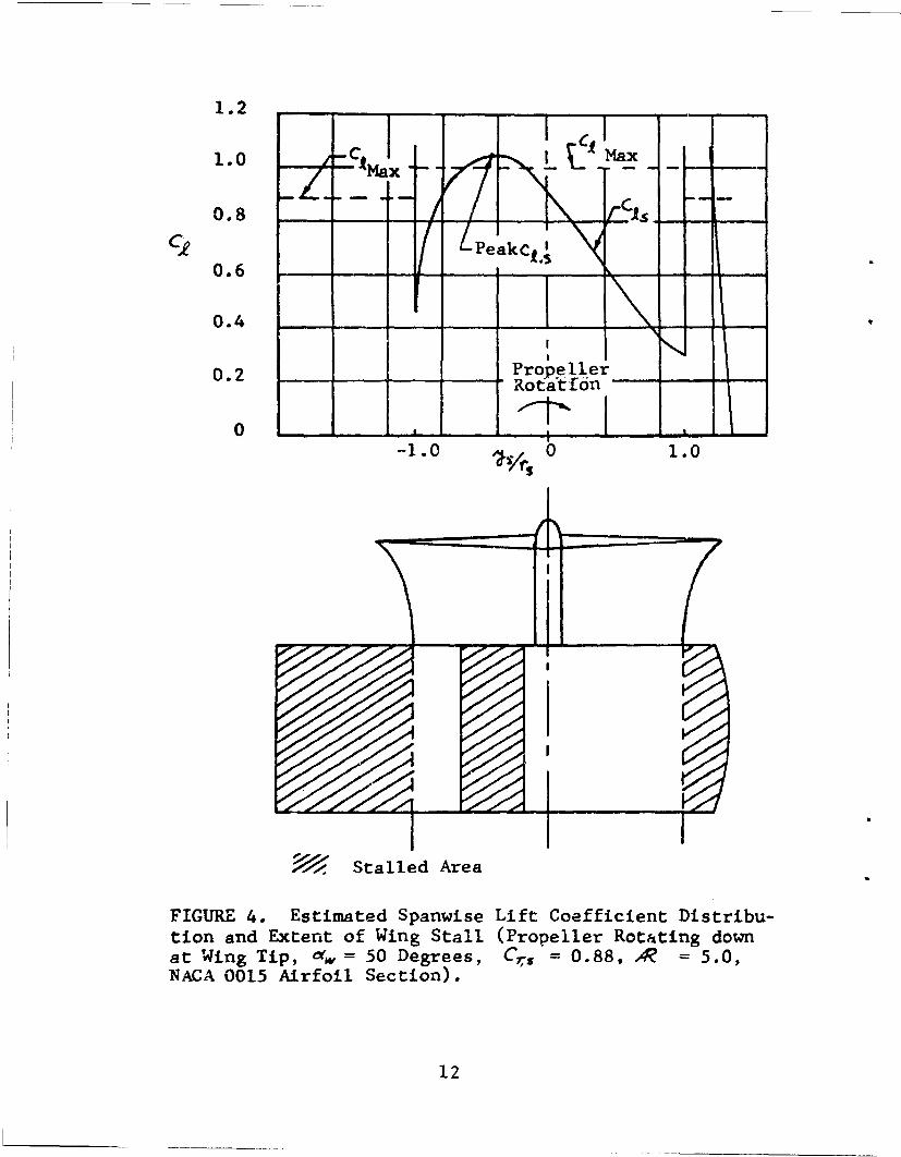
5 Estimated Spanwise Lift Coefficient Dis-tribution and Extent of Wing Stall (Pro-peller Rotating Up at Wing Tip, A = 50Degrees, CQn = 0,88, 4 = 5.0, NACA 00L,Airfoil Section) ............... 13
6 Correlation of Estimated Wing Stall WithinSlipstream with Test Data .................. 14
7 Estimated Longitudinal Force Coefficientsfor a 3500-Pound, Tilt-Wing VTOL Aircraft,Showing Conditions of Ck = 0 ............. 19
8 Effects of Wing Size on Lift CoefficientDuring Transition Maneuver of a 3500-Pound,Tilt-Wing VTOL Aircraft ................... . 20
viii
Figure Page
9 Effects of Wing Area on Airspeed VersusWing Angle of Attack for a 3500-Pound,Tilt-Wing VTOL Aircraft ................... 22
10 Effects of Aspect Ratio (Wing Size) on PeakLocal Lift Coefficient and Stall within theSlipstream for a 3500-Pound, Tilt-Wing VTOLAircraft ............................... .... 23
11 Estimated VTOL Stall Regime as a Function ofAspect Ratio (Wing Size) for a 3500-Pound,Tilt-Wing VIOL Aircraft (Wing Span 24.88Feet) ......................... ............... 24
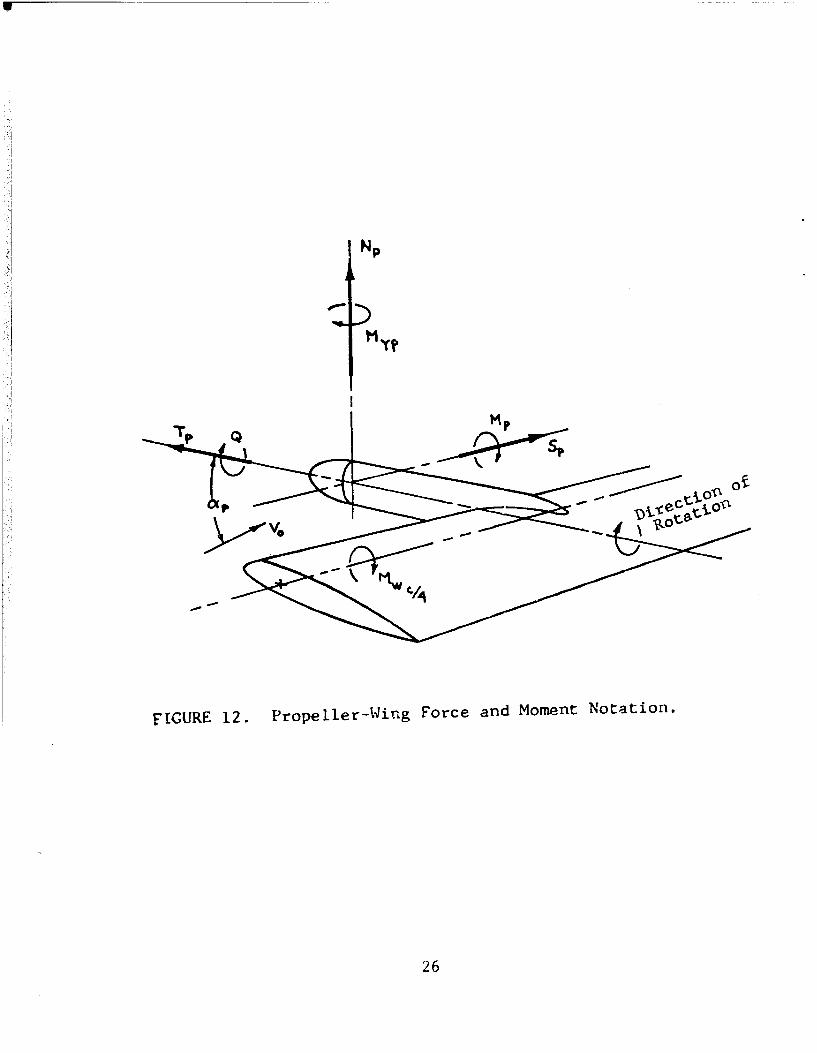
12 Propeller-Wing Force and Moment Notation ... 26
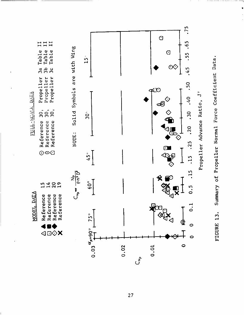
13 Summary of Propeller Notrmal Force CoefficientData ............................. .......... 27
14 Effect of Propeller Blade Pitch, A , on Pro-peller Normal Force Coefficient,C>,Y, ....... 29
15 Effect of Wing on Propeller Normal ForceCoefficient ................................ 31
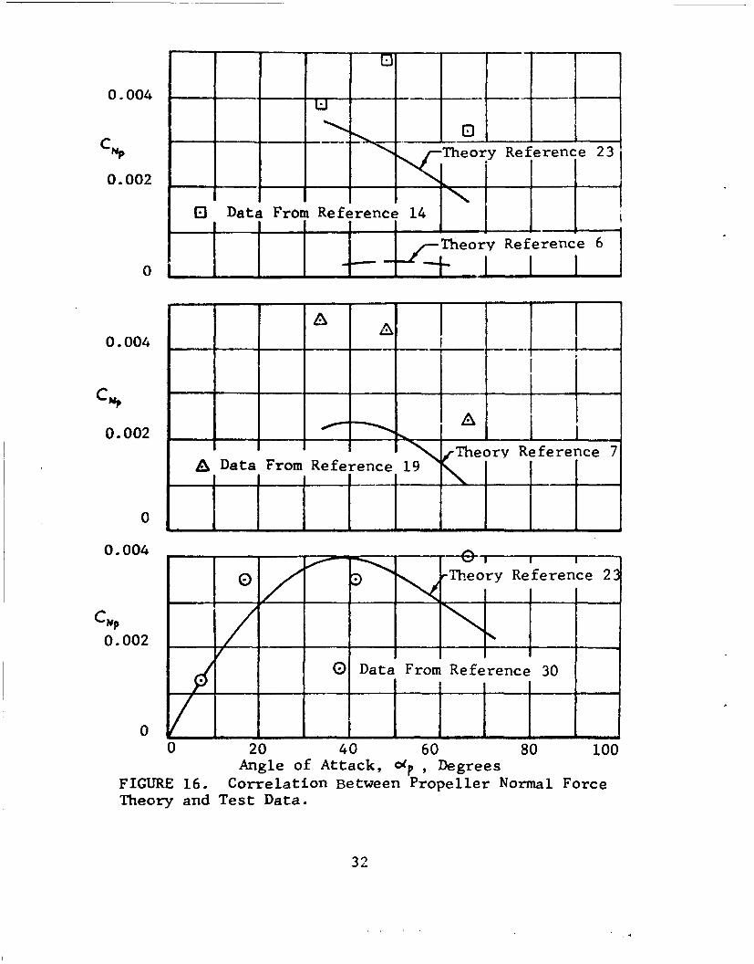
16 Correlation Between Propeller Normal ForceTheory and Test Data ....................... 32
17 Sunmiary of Propeller Pitching Mome.ntCoeffi cient Data .0. . . . . .. ........ ... .. .. 33
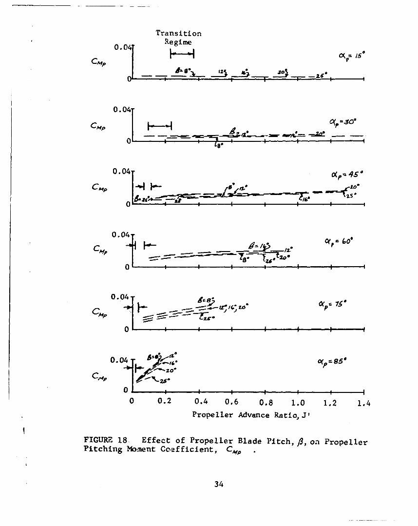
18 Effect of Propeller Blade Pitch, /3 , on Pro-peller Pitching Moment Coefficient, CMp ... 34
19 Effect of Wing on Propeller Pitching MomentCoefficient ...... .o.00 0............ ... .. .. . 35
ix
qw
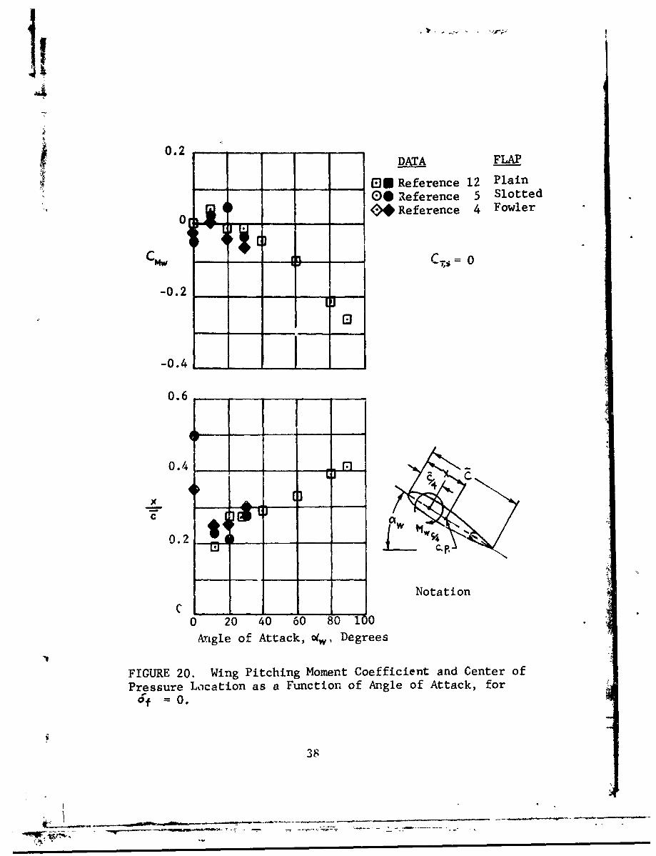
20 Wing Pitcbirng n Pent Coefficient andCenter of Pressure Location as a Function3f Aagle of Attack, for • = 0 .............. 38
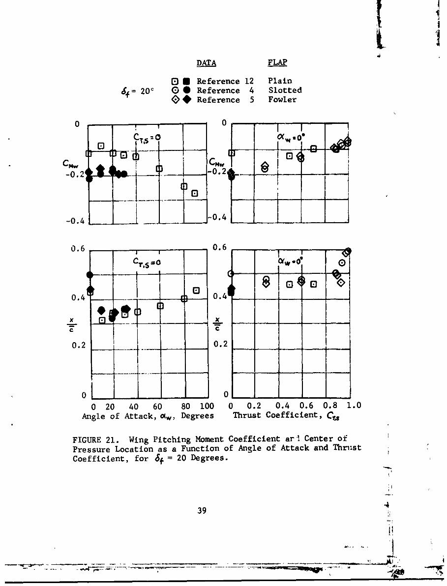
21 Wing PItching Moment Coefficient and Centerof Pressure Location as a Function of Angleof Attack and Thrust Coefficient, for Jfc= 2C Degrees ................ ......... ................... 39
22 Vin.g Pitchir.g .4onent Coefficient and Centerof Pressure Locatior. as a Fnctior. of Angleof attack and Thrust Coefficient, for JIc= 40 degrees................................ 40
23 WIn4g Pitching Nownt Coefficient and Cenzerof •ressure Locatior. as a Furction of Angleof Attack and Thrust Coefficienc, for df= 50 Degrees ............................. 41
24 iiing Pitching Mment Coefficient and Cu.terof Pressure Locaticn as a Furction of Angleof Attack and Thrust Coeificient, for d4'= 'W0 and 70 Degrees ......................... .42
25 ?-.tcz.-g .Nwwnt Coeificient Breakdown. fora iii.g meIrsed i- Propeller Slipstreanus.... 44
26 $lipstrezz Effects o.n ain.g DcI. sh AL.gle(Crta fr.m elference 15) .................... 46
27 Slipstrean Effects on .irfiow Velocity inthe Vicinity of a "IOL's Hcrizontal Tail (Datafrca Reference 15) .......................... 47
A2Ircraft Arcelerations Following PartialLngine Failure .............................. 50
79 Geral Arrazgement of a VIOL TransportAircraft..................................... 52
3C Force and Moamnt Notation ...................... 54
x
Finure Page
31 Profile Drag Coefficients of a WingEquipped with a Fowler Type Flap .......... 76
32 Analog Computer Schematic for VTOLLongitudinal Stability .................... 82
33 Transient Response of Unstabilized Air-craft to a Pulse Disturbance (Vo = 30 Knots). 84
34 Transient Response with Vertical VelocityFeedback Stabilization (Vo = 3G Knots) .... 85
35 Transient Response with Vertical VelocityFeedback Stabilization (Vo = 30 Knots) .... 86
36 Transient Response with Attitude FeedbackStabilization (Vo = 30 Knots) ............. 88
37 Transient Response with Attitude FeedbackStabilization (Vo = 30 Knots) ............. 89
38 Transient Response w.th Attitude FeedbackStabilization (Vo = 30 Knots) ............. 90
39 Transient Response with Vertical Velocityand Attitude Feedback Stabilization(Vo Z 30 Knots) .......................... 91
40 Transient Response of the Unstabilized Air-craft with Reduced Values of Npt and Mpd(V = 30 Knots) ............. 92
41 Transient Response of Unstabilized Aircrzftto a Pulse Disturbance (Vo = 70 Knots) .... 94
42 Transient Response with Vertical Velocityand Attitude Feedback Stabilization(vo = 70 Knots) ......................... 95
Figure Page
43 Circular Jet with Four Concentric VelocityZones ....... ............................... 977
44 Circular Jet with Two Concentric VelocityZones ..... .......... ................. ...... 99
45 Dynamic Pressure Survey Behind Propeller(Reference 2, Figure 7; Wing Removed,
- 1.0, T = 25 Pounds) ............... 108
46 Variation of Lift Coefficient Increment withFlap Deflection Angle (Test Data fromReference 12, Figure 9a; Plain Flap,
C r, = 1 .0 ) ........... ...... .................*........ 112
47 Variation of Lift Coefficient Increment withFlap Deflection Angle (Test Data fromReference 2, Figure 5a; Plain Flap,
C'r$ 1.0) ............................... 11
48 Variation of Lift Coefficient Increment withFlap Deflection Angle (Test Data fromReference 13, Figure 7a; Single-Slotted Flap,
Cr{ = 1.0) ........................ ....... 114
49 Variation of Lift Coefficient Increment withFlap Deflection Angle (Test Data fromReference 4, Fowler Type Flap, cf/c = 0.4,
CTS = 1.0) ........ ....... ............ ... 115
50 Effect of Wing Incidence on Lift Coefficient(Test Data from Reference 13, Figure 9 a;Double-Slotted Flap, Crs = 1.0) ........... 117
xii

SYMBOLS
Aj cross-sectional area of fully developed
slipstream, square feet
A? wing aspect ratio
a basic wing lift curve slope, per radian
0 airfoil section lift curve slope, per radian
ax aircraft longitudinal acceleration, feet persecond per second
01 aircraft vertical acceleration, feet persecond per second
b wing span, feet
bs distance from wing root to slipstreamcenterline, feet
CIO* section profile drag coefficient of wingarea not immersed in slipstream (evaluatedat free stream wing geometric angle of attack)
Cor fuselage profile drag coefficient
section profile drag coefficient of wingarea immerseo in slipstream (evaluated atslipstream wing geometric angle of attack)
cot. tail profile drag coefficient
cow wing drag coefficient, including effect ofslipstream, DO, S
CM pitching moment coefficient, M416SZ
xiii

C1 basic wing lift coefficient
C4S total lift coefficient, including contribu-tions due to propeller thrust and normalforce components, and effect of slipstream,based on y.
,a C" increment of lift coefficient due to effectof slipstream
CIW wing lift coefficient, including effect ofslipstream, Lw/,IS
C, airfoil section lift coefficient; also local
wing lift coefficient
Cl•nz airfoil section maximumm- lift coefficient
C,•.k •maximum local wing lift coefficient of wingarea immersed in slipstream, based on s
local lift coefficient of wing area itmersedin slipstream, based on
increment of local lift coefficient due toeffect of slipstream
CA~p propeller pitching moment coefficient,Mp/en2 4D
CO's total pitching moment coefficient aboutwing quarter-chord, including contributionsdue to propeller pitching moment and normalforce, and effect of slipstream
CN-V wing pitching moment coefficient, Mw/ySz
CNP propeller normal force coefficient,
xiv
-A -- ---
CP propeller power coefficient, P/ln-Of
C~q propeller torque coefficient, Gp!2i
Cr propeller thrust coefficient, Tvp/3'/rDY4)
c; propeller thrust coefficient, -p/en'04
C4 propeller thrust coefficient, 7,/•,(iTr¼)
Cos longitue.nal force coefficient, ./q•S
C wing chord, feet
Z average wing chord, feet
¢, flap chord, feet
C wing chord at slipstream centerline, feet
c.S. center of gravity
C.p. center of pressure
D propeller diameter, feet
DC fuselage drag, pounds
Dt tail drag, pounds
Dw wing drag, including effect of slipstream,
pounds
Dw,, Dwt wing drag derivatives
5?acceleration due to gravity, feet per
second per second
IYY aircraft pitching moment of inertia, slag-square feet
xv

- - .B '-- m-• --'- o• '
IP • geometric angle between propeller thrustaxis and X-axis, radians
ir angle of incidence between propeller thrustaxis and wing-chord line, radians
geometric angle between wing-chord line and
X-axis, radians
J propeller advance ratio, V./nD
propeller advance ratio, V. cosopl/nD
j index number
empirical constants for correction ofadditional angle of attack due to flapdeflections
slipstream stabilizer constants
basic wing lift, pounds
4F fuselage lift, pounds
Lt tail lift, pounds
LW wing lift, pounds
LW" ,L W(wing lift derivatives
I distance from c.g. of aircraft to quartex-chord of horizontal tail, feet
M, Mc~g. aircraft pitching moment about c.g. ofaircraft, pound-feet
fuselage pitching moment, pound-feet
1kp propeller pitching moment, pound-feet
)CA
- -A-
propeller pitching moment derivatives
Mu,mw,,... aircraft pitching moment derivatives
Mw¼ wing pitching moment about wing quarter-chord, pound-feet
MYP propeller yawing moment, pound-feet
Mn mass, slugs
N number of propellers
Alp propeller rormal fo--e, pou:±ds
NMr tail rotor normal force, pounds
n propeller rotational speed, revolutionsDer second
no propeller rotational speed preceding engine
power failure, revolutions per second
P propeller power, foot-pounds per second
Q propeller torque, pound-feet
70 i:ee stream dynamic pressure, pounds persquare foot
Y slipstream dynamic pressure, pounds persquare foot
Rn reynolds number
rs radius of fully developed slipstream, feet
•,z •radii of slipstream velocity zones, feet
S total wing area, square feet
xvii
Sp propeller side force, pounds
$S. slipstream-immersed wing area, j-uare feet
P propeller thrust, pounds
_r tail rotor thrust, pounds
U slVpstream-induced velocity in fully developedslipstream, feet per second
ti U2 slipstream-induced velocities, feet persecond
UO nondimensionalized slipstream-inducedvelocity
U', nondimensionalized slipstream-inducedvelocities
U longitudinal component of free stream
velocity, feet per second
14 free stream velocity, feet per second
V velocity of fully developed slipstream,feet per second
t airflow velocity at horizontal tail, feetper second
vl, V2 slipstream velocities in velocity zones,
feet per second
4/ aircraft gross weight, pounds
w normal component of free stream velocity,feet per second
force acting in X-axis direction, pounds
xviii
)•,,X•,... derivatives of forces actiA in the X-axis
direction
X longitudinal distance from wing leading-edge,
feet
XPw,"• distances in X-axis direction, feet
spanwise distance from wing root, feet
XS spanwise distance from slipstream center-line, positive towards wing tip, feet
y nondimensionalized spanwise distance from
slipstream centerline, yX/4
Z force acting in Z-axis direction, pounds
ZW ,.'" derivatifves of forces acting in Z-axisdirection
vertical distance from wing trailing-edgeto plane of horizontal tail, feet
distances in Z-axis direction, feet
effective wing angle of attack withoutslipstream, o•w - L* 4- 40(F , radians
Cý4 angle of zero lift of basic airfoil section(with no flap), radians
oýF angle of attack between X-axis and freestream, radians
60( change in wing effective angle of attackdue to flap deflection (without slipstream),radians
xix
Oip angle of attack between propeller thrustaxis and free stream,.radiLns
42 spanwise local change in wing angle ofattack due to slipstream rotation, radians
01(5 mean effective wing angle of attack inslipstream, # + 4'r -o +o - , radians
OSC effective wing angle of attack at slip-
stream centerline, radians
0( horizontal tail angle of attack, radians
O/W wing geometric angle of attack, radians
•G) propeller blade pitch at three-quarterblade radius, degrees
aircraft climb angle, radians
6 slipstream stabilizer deflection, radians
Jcwing trailing-edge flap deflection angle,radians
ratio of slipstream induced velocities intwo velocity zones
ratio of radii of slipstream velocity zones
E downwash angle at tail, radians
wing twist from slipstream centerline toperiphery, radians
e fuselage attitude, radians
1 ratio of free stream to jet velocity
xx
mass density of air, slugs per cubic foot
deflection angle of resultant slipstreamflow from propeller thrust axis (slipstreamvelocity assumed uniform and irrotational),radians
velocity potentials
xxi
INTRODUCTION
The present work is a continuation of the inves-tigation of propeller-wing aerodynamics reported inReference 3. In Reference 3, simple analytical expres-sions are presented for the lift and drag of a wingimmersed in propeller slipstream. These expressions werecorrelated with experimental data and it was found thatfair to good agreement is obtained for unstalled wings.Also, a preliminary investigation of wing stall was pre-sented. Furthermore, the previously mentioned expressionswere utilized to evaluate the use of slipstream to augmentstability and it was found that the use of a servo-flap onthe wing trailing edge results in positive dynamic stabilityin the hovering flight condition.
In the program reported herein the problem ofwing stall is further investigated and an expression isgiven for the determination of wing stall within theslipstream. This expression is then utilized to formulatea method for the determination of the minimum wing sizefor stall-free transition of tilt-wing type VTOL aircraft.The above analyses for stall and minimum wing size arepresented in the two following sections.
The effect of propeller-wing interaction onpitching moments is presented in the section titledPropeller and Slipstream-Induced Moments. Data aregiven for propeller normal force and pitching moment withand without the presence of a wing. Furthermore, the effectof propeller slipstream on wing pitching moment and centerof pressure is examined for a range of flap deflections.In addition, slipstream effects on the horizontal tail arediscussed.
The next topic in the present investigation per-tains to stability during the transition maneuver and ispresented in the section title Slipstream Effects on VTOLAircraft Stability. The derivatives, which in Reference 3are obtained for the hovering flight condition, areextended to the transition conditions. A number of stabil-ization augmentation systems are investigated by means ofan analog computer study.
I
In the section titled Modification ofSlipstream to Augment Lift and Control, an analysis_s ade on the possibility of increasing the liftof a slipstream-immersed wing by changing thepropeller-induced velocity profile of the slipstream.Finally, the effects of large flap deflections, wingtuist and relative propeller-wizg orientation and posi-tion on 'wing lift are investigated.
II
(
f--
--
STALL OF A WING IMERlSED IN PROPELLER SLIPSTREAM
Wing stall constitutes a serious problem ifencountered during the transition maneuver of a ttilt-wingVTOL aircrift. The stalled wing not only modifies the liftand drag characteristics of the aircraft but also has anadverse effect on stability and control.
In formulating a method for the orediction ofstall of a wing innersed in a slipstream, it is useful toreview the analyses which are being utilized for conven-tional wings.
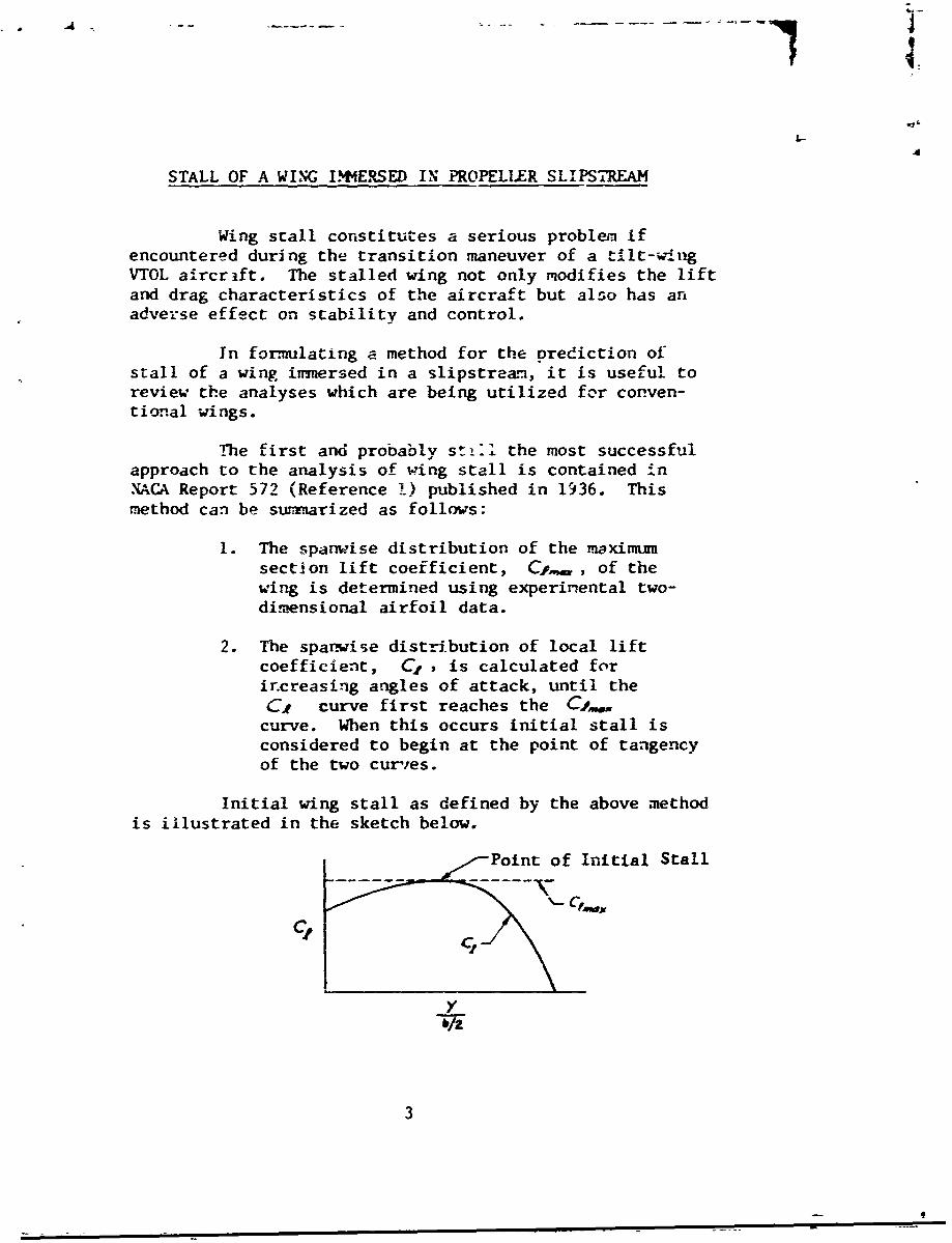
The first and probably still the most successfulapproach to the analysis of wing stall is contained inXACA Report 572 (Reference !) published in 1936. Thismethod can be suxnarized as follows:
1. The spanwise distribution of the maximumsection lift coefficient, C,,,, , of thewing is determined using experimental two-dimensional airfoil data.
2. The spanwise distr-ibution of local liftcoefficient, C, , is calculated forir.creasing angles of attack, until theC, curve first reaches the C,..
curve. When this occurs initial stall isconsidered to begin at the point of tangencyof the two cur';es.
Initial wing stall as defined by the above method
is illustrated in the sketch below.
Point of Initial Stall
c,
3 i,/t.
Jt
As reported in Reference 8 the above method hasbeen used with success in analyzing unswept wings of mildtaper.
Following World War II, the above method wasapplied to the analysis of swept wings, but it was foundthat the resulting stall predictions were less accurate thanthose for unswept wings. In part this is due to the bound-ary layer flow which for swept wings is significantly dif-ferent from what occurs on a two-dimensional airfoil.As indicated in Reference 8, the difference in boundarylayer conditions is, for the most part, due to the spanwisecomponent of velocity over the swept wing, although thewing planform also contributes to this difference. Inspite of these inaccuracies, the above method provides use-
ful results for the swept wing in that it gives a conserva-tive estimate of the condition of initial stall.
It is assumed that this method is applicable alsoto wings partially or fully immersed in a slipstream. Theformulation of the appropriate equations for the wing-pro-peller case is now presented.
STALL ANALYSIS
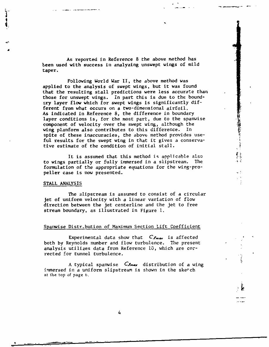
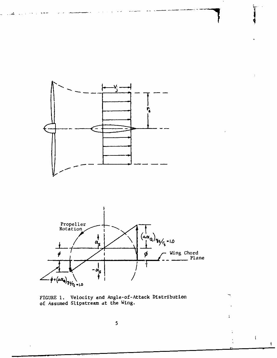
The slipsuream is assumed to consist of a circularjet of uniform velocity with a linear variation of flowdirection between the jet centerline and the jet to freestream boundary, as illustrated in Figure 1.
Spanwise Distribution of Maximunm Section Lift Coefficient
Experimental data show that C is affectedboth by Reynolds number and flow turbulence. The presentanalysis utilizes data from Reference 10, which are cor-rected for tunnel turbulence.
A typical spanwise Cfm•x distribution of a wingimmersed in a uniform slipstream is shown in the sketchat the top of page b.
4
9 m - - - -
VCl
PropellerRotation
Lr .0 rWing Chord
Plane
S,, /
FIGURE 1. Velocity and Angle-of-Attack Distributionof Assumed Slipstream at the Wing.
5
.am+
Wing Tip
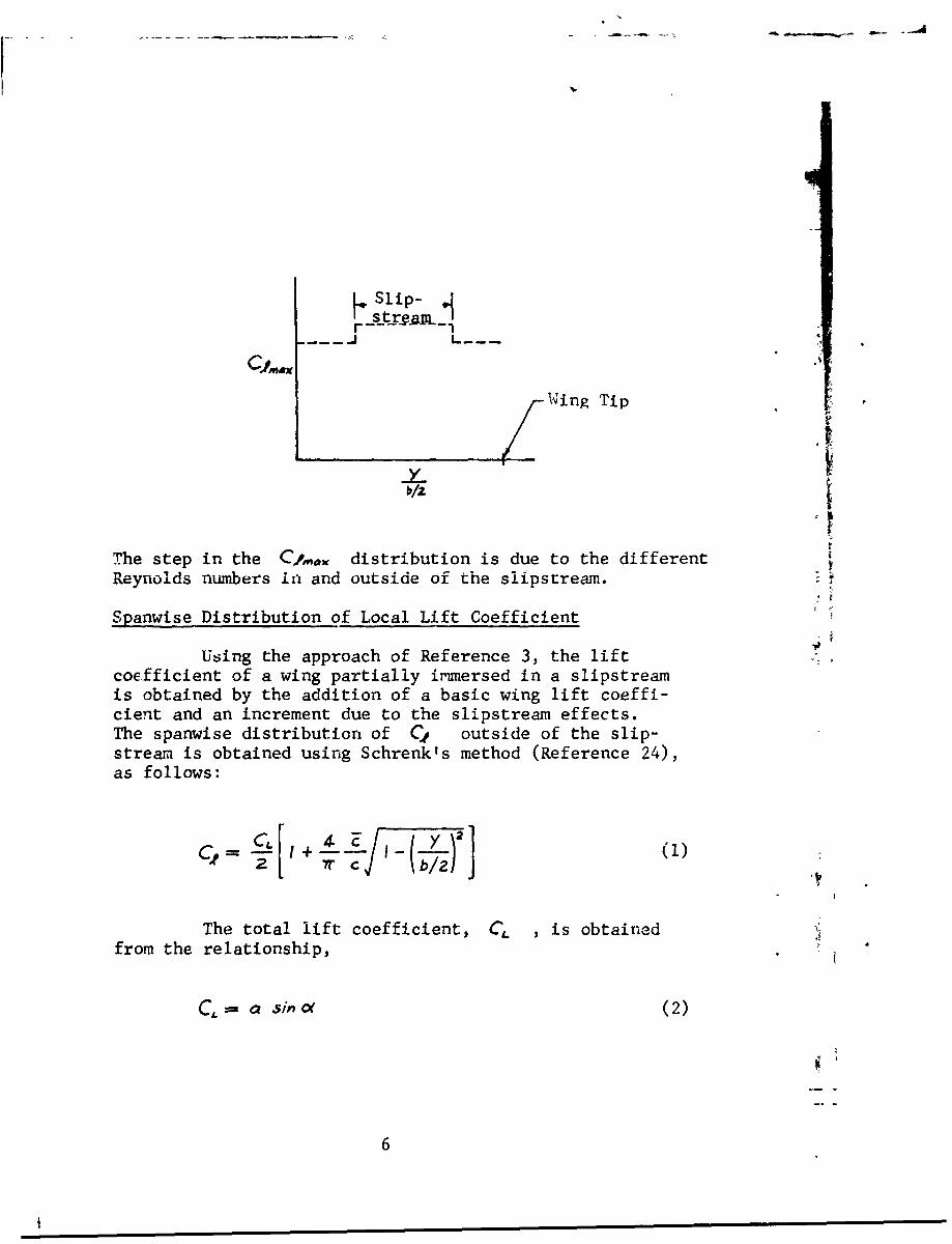
The step in the C distribution is due to the different
Reynolds numbers in and outside of the slipstream.
Spanwise Distribution of Local Lift Coefficient
Using the approach of Reference 3, the liftcoefficient of a wing partially irmmersed in a slipstreamis obtained by the addition of a basic wing lift coeffi-cient and an increment due to the slipstream effects.The spanwise distribution of C* outside of the slip-stream is obtained using Schrenk's method (Reference 24),as follows:
The total lift coefficient, C. , is obtainedfrom the relationship,
CL =a Sin Of (2)
6

4
where
F, , a.PI
In Equation (2), sing is used rather then oto better approximate C, at large values of cel .
Within the slipstream, the basic distribution,Equation (1), is modified to account for the slipstreamdynamic pressure and is expressed in terms of Ys/rsThe equation for the increment lift coefficient, A C3,is obtained from Reference 3. Hence, the lift coefficientdistribution inside the slipstream is given by
-. -+~ •(3)
For a rectangular wing, Z/c = 1, and
LCjs- 1 f'"l''I' '• ]'',b/2 I]q
I+7- t 4)
where
a's= + i (- •+•-• (5)
The term AcKq accounts for the change in local angle ofattack due to slipstream rotation, and is given by
7
~~ --
-) r
I.C' C,
CORREIATION
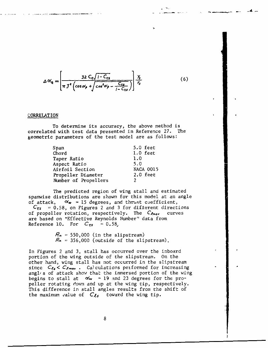
To determine its accuracy, the above method iscorrelated with test data presented in Reference 27. Thegeometric parameters of the test model are as follows:
Span 5.0 feetChord 1,0 feetTaper Ratio 1.0Aspect Ratio s5n
Airfoil Section NACA 0015Propeller Diameter 2.0 feetNumber of Propellers 2
The predicted region of wing stall and estimatedspanwise distributions are shown for this model at an angle
of attack, <yw = 15 degrees, and thrust coefficient,Crs = 0.58, on Figures 2 and 3 for difterent directions
of propeller rotation, respectively. The Cz,,, curvesare based on "Effective Reynolds Number" data fromReference 10. For Crs = 0.58
Rn = 550,000 (in the slipstream)Rn = 356,000 (outside of the slipstream).
In Figures 2 and 3, stall has occurred over the inboard
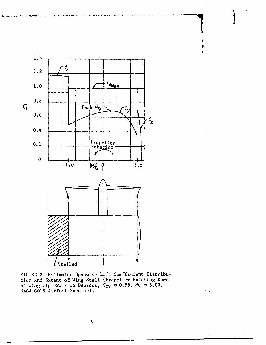
portion of the wing outside of the slipstream. On theother hand, wing stall has not occurred in the slipstreamsince C>s < Cima . Calculations petformed for increasingangl's of attack show that the immersed portion of the wingbegins to stall at •w = 19 and 23 degrees for the pro-peller rotating down and up at the wing tip, respectively.This difference in stall angles results from the shift ofthe maximum value of C1s toward the wing tip.
8
1.4
1.2 __
1.0 4,ax
0.8Pe k 1
0.6
0.4
0. 2 PropellerRotation
0- 0 A
/ir? A. V
FIGURE 2. Estimated Spanwise Lift Coefficient Distribu-tion and Extent of Wing Stall (Propeller Rotating Downat Wing Tip, ocw 15 Degrees, Cr - 0.58, IR =5.00,NACA 0015 Airfoil Section).
9
1.4
1.2
1.0 x
0 .8 _ _P e ak__ _
C 2 c0.6 - ____ _ _
0.4 -
0.2 PropellerRotation
-1.0 YS/O 0I10
/stalled
FIGURE 3. Estimated Spanwise Lift Coefficient Distribu-tion and Extent of Wing Stall (Propeller Rotatine up &.tWing Tip, c~w = 15 Degrees, Crs =0.58, R~ 5:00,NACA 0015 Airfoil Section).
10
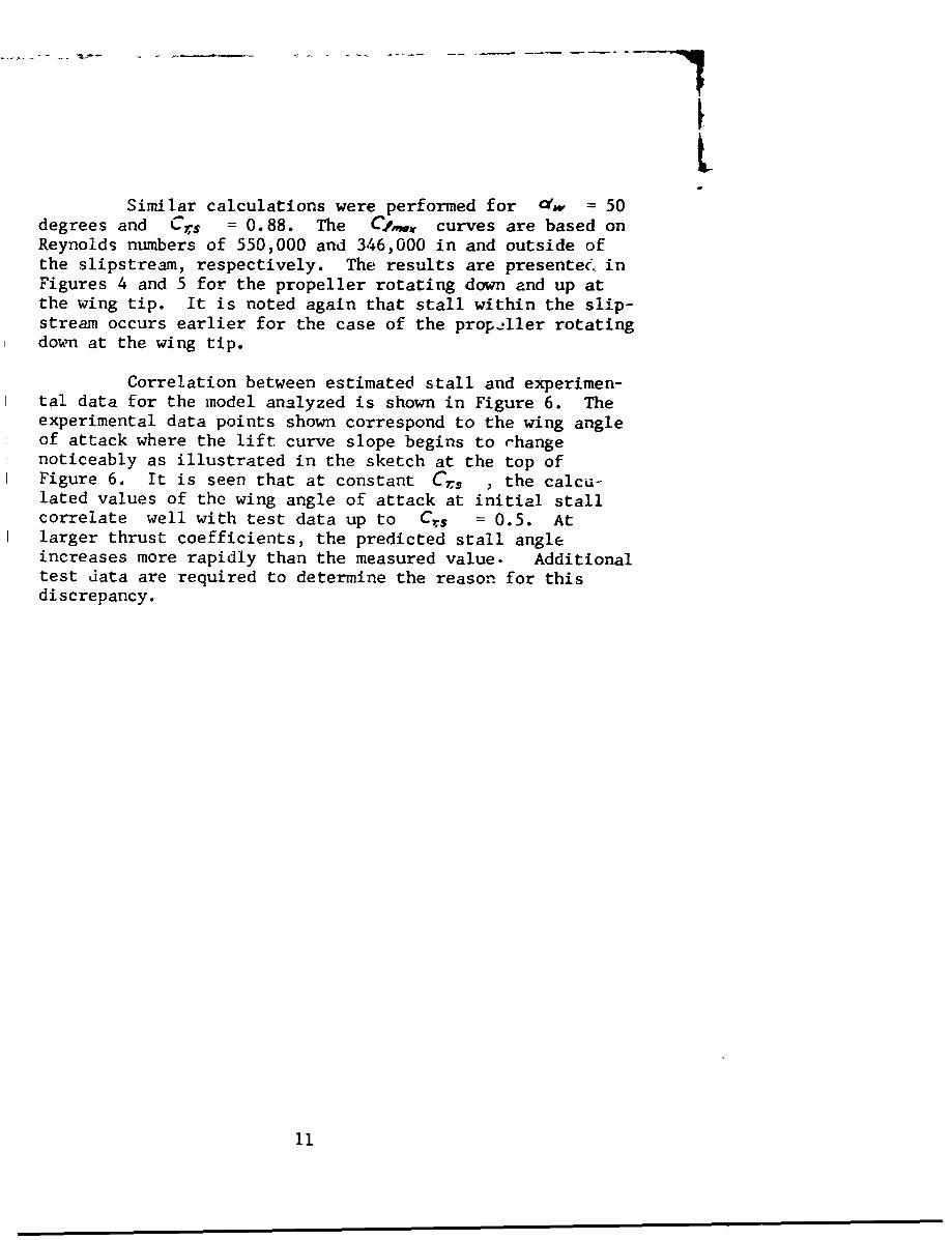
Similar calculations were performed for 'w = 50degrees and Crs = 0.88. The C2, curves are based onReynolds numbers of 550,000 and 346,000 in and outside ofthe slipstream, respectively. The results are presentee inFigures 4 and 5 for the propeller rotating down and up atthe wing tip. It is noted again that stall within the slip-stream occurs earlier for the case of the prop-ller rotatingdoum at the wing tip.
Correlation between estimated stall and experimen-tal data for the model analyzed is shown in Figure 6. Theexperimental data points shown correspond to the wing angleof attack where the lift curve slope begins to rhangenoticeably as illustrated in the sketch at the top ofFigure 6. It is seen that at constant Crs , the calcu-lated values of the wing angle of attack at initial stallcorrelate well with test data up to C,$ = 0.5. Atlarger thrust coefficients, the predicted stall angleincreases more rapidly than the measured value. Additionaltest data are required to determine the reason for thisdiscrepancy.
11
1.2
1.0 I a--Max'-
0.8 / \7N,C2
0.6 / PeakcdI••,
0.4
0.2 Prope ller"Rotat [on
0 1-1.0 0 1.0
. Stalled Area
FIGURE 4. Estimated Spanwise Lift Coefficient Distribu-tion and Extent of Wing Stall (Propeller Rotating downat Wing Tip, yw = 50 Degrees, Cr,s = 0.88, AR 5.0,NACA 0015 Airfoil Section).
12
1.2
1.0Peak CRx
0.8
0.6
0.4 _
0.2 ProplelerRotation
0 1 A-T"'-1.0 0•,, o 1.0
• Stalled -Area
FI'URE 5. Estimated Spanwise Lift Coefficient Distribu-tion and Extent of Wing Stall (Propeller Rotating Up atWing Tip, c'. =50 Degrees, C7s = 0.88, A =5.0, NACA0015 Airfoil Section).
13

SLw Point of Initial Stall
90 I I
A:= 5.0a - -0- - - NACA 0015 Airfoil Section-
3,: Propeller Rotationr 70 --- Down At Wing Tip
S0 E) Data-Reference 27
0 60-0 /~44~
C) ~50
E2400 0 Estimated Stall
$4
C,,
10
0 0.2 0406 .Thrust Coefficient, C1,
FIGURE 6. Correlation of Estimated Wing Stall WithinSlipstream with Test Data.
14

MINIMUM WING SIZE FOR VTOL AIRCRAFTTRANSITION WITHOUT STALL
The stall analysis of the preceding section isnow utilized to determine the minimum wing size for VTOLaircraft transition without stall of the slipstream-immersedportion of the wing. This is accomplished as follows:
1. For an aircraft of a particular gross weightand configuration, a wing size is selected inaccordance with the mission requirement of theaircraft, i.e., high-speed flight or stalling-speed considerations. Also, the span shouldbe such that most of the wing is immersed withinthe propeller slipstreams.
2. Next, the trim values of the thrust coefficient,Crs ,and airspeed, V. , are determined for
a number of wing tilt angles between 10 to 90degrees. This is accomplished by use of thelift and drag equations of Reference 3. First,at a selected wing tilt angle, the total longi-tudinal force coefficient, Cx.s , includingfuselage and tail drag, is calculated using thefollowing expression (all angles in degrees):
c Z ND
rNDO 1C
Ci, 4 rs ", a0038_'A OS(l
0(0,6 3 1(7
15Ds~
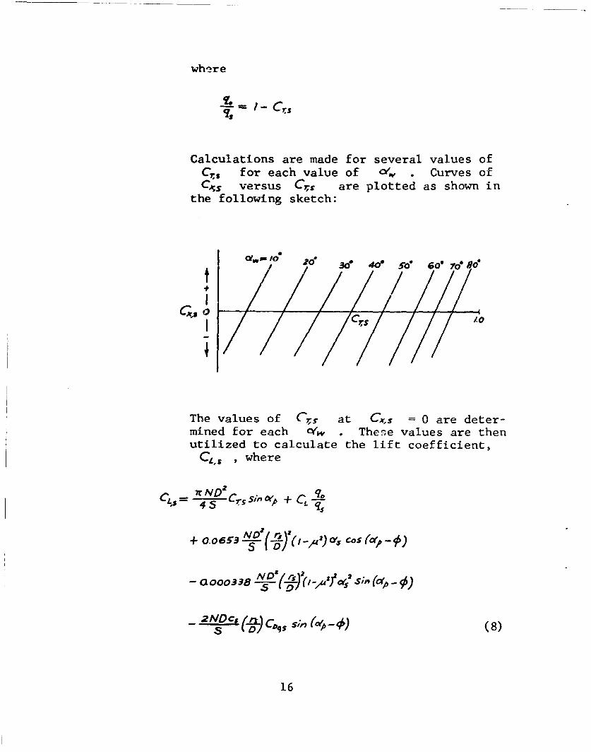
where
Calculations are made for several values ofCr,s for each value of 04 • Curves ofC~s versus Crs are plotted as shown in
the following sketch:
, ,0 o 3d0" 4e so 60" 7do 50'
The values of C61s at Cxs= 0 are deter-mined for each O(w o Thene values are thenutilized to calculate the lift coefficient,
CI'S , where
CL. 7=r ND2 CrS Sin WA + Ct qO45
+ O.o6573.!(-) (Ir* c5cp~
- aooo338 ND I), (•,C'i s -p)
2N o,(8)
16
Next, the airspeed is calculated as follows:
=/ 2WQ-Cr,-c (9)
3. The spanwise lift coefficient distribution ofthe slipstream-immersed portion of the wing iscalculated for each trim condition usingEquation (4). The resulting peak values of
Ct., are plotted versus o4 ,
4. The local Cf,%e corresponding to the peakvalue of Cts in step 3 above is determinedas discussed in the preceding section. Thesevalues are plotted on the same graph as the
Cs values in step 3 above.
5. If the maximum value of Cjs is nearly equalto but not greater than the corresponding valueof C), , the wing size selected above corre-sponds to the minimum size for stall-free tran-sition.
6. If the above is not the case, the calculationprocedure is repeated for another wing size,and so on, until the condition of step 5 issatisfied.
To illustrate the above procedure sample calcula-tions were performed and the results of these calculationsare now discussed.
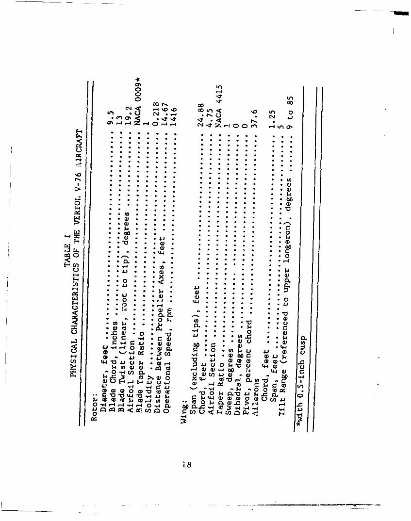
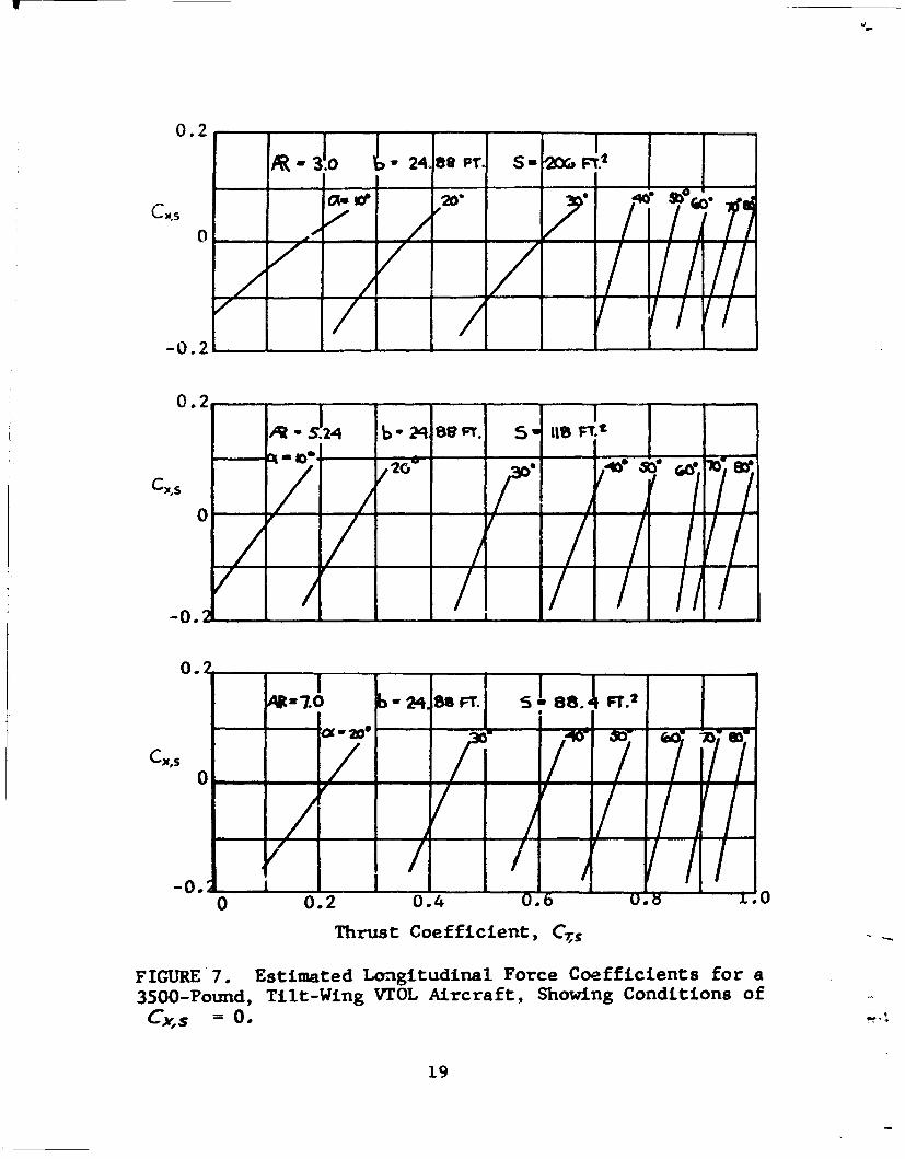
The basic aircraft analyzed corresponds to theVertol V-76. The characteristics of this vehicle aresummarized in Table I. Calculations were performed forthree different wing chords, at constant wing span, corre-sponding to aspect ratios of 3.0, 5.24,and 7.0. The calcu-lated values of the longitudinal force coefficient, Cmsare presented in Figure 7. The trim values of total liftcoefficient, C&s , are presented in Figure 8
17
0 '-4
C- -4OD 00 rl 'LnUtn * C14 %D- * n 0%
tt *< .
0* . * 5 * *1* *
0 so . . . . . . .
o CD
(D -7 . . . 0 * *0
C) -V 0
~~~( o W
(LI .. , w 0 (D *1 p * * * *En 44 4 0) (1 4 u o p u .w . (D (L -4 4) d) -r4 * * * 00 '
x; - 0 r4 *l m U Q)) to 41 W - 0 44 *
CC u r4 r-< ý4. cc L n.13 '0 44 *0 -r 4J $4P 0) d* * ) 0 4) U W 4co p. to 4 W. ) **1 0) P , 41 X > 4 "4.*1C o m m.n Q -. : O U<.F.En.A..-0 V4 L
srf * * 18
-0.2-L- -A-
0.2
1-Sf4 b 2, 89 Fr. 5 itsFr.t
-X' - - 0- -3 0 r e 1
o /0.2
74W b - 24. 88 FT. 5 i8. T.2
cx's
-0.2 1
Cs 0.7
0-0.2 0-,4 . 0 .0FT.1
Thus Cofi cien , iTl
FIGURE 7. Estimated Longitudinal Force Coefficients for a3500-Pound, Tilt-Wing VTOL Aircraft, Showing Conditions of
19

2.4
2.0 (S 99A
-' 1.2
o /-- - 3.o
0.80.4
S~NACA 0015 Airfoil Section
0 10 20 30 40 50 60 70 80 90
Angle of Attack,, c(,, Degree3
FIGURE 8. Effects of Wing Size on Lift Coefficient DuringTransition Maneuver of a 3500-Found, Tilt-Wing VTOL Aircraft.
20
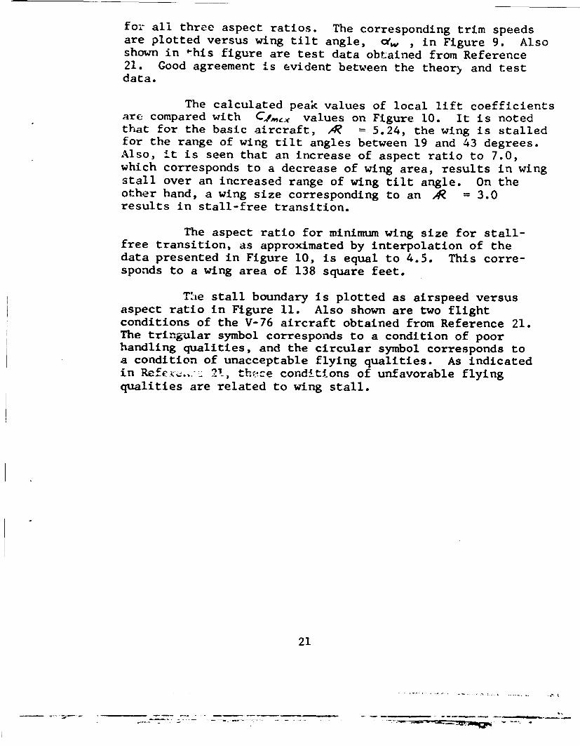
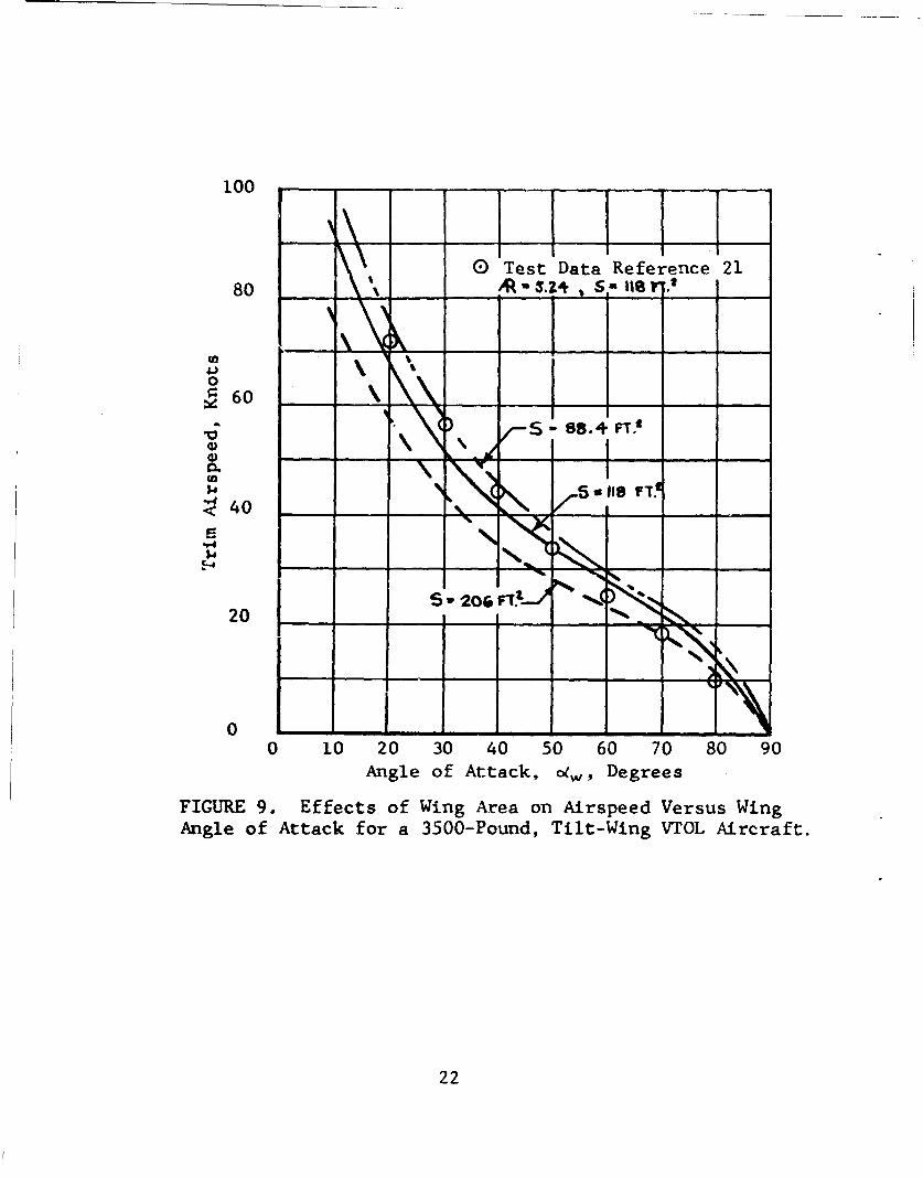
for all three aspect ratios. The corresponding trim speedsare plotted versus wing tilt angle, cf. , in Figure 9. Alsoshown in *his figure are test data obtained from Reference21. Good agreement is evident between the theory and testdata.
The calculated peak values of local lift coefficientsare compared with C1 ,,, values on Figure 10. It is notedthat for the basic aircraft, A = 5.24, the wing is stalledfor the range of wing tilt angles between 19 and 43 degrees.Also, it is seen that an increase of aspect ratio to 7.0,which corresponds to a decrease of wing area, results in wingstall over an increased range of wing tilt angle. On theother hand, a wing size corresponding to an A = 3.0results in stall-free transition.
The aspect ratio for minimum wing size for stall-free transition, as approximated by interpolation of thedata presented in Figure 10, is equal to 4.5. This corre-sponds to a wing area of 138 square feet.
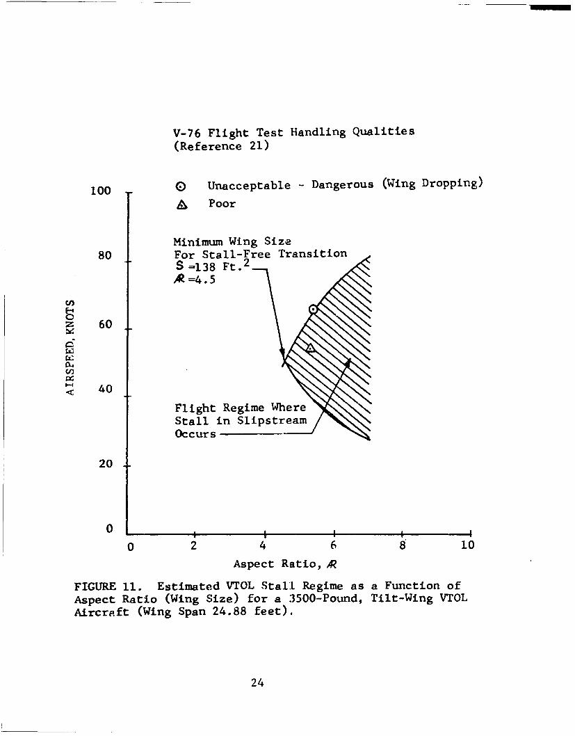
T!he stall boundary is plotted as airspeed versusaspect ratio in Figure 11. Also shown are two flightconditions of the V-76 aircraft obtained from Reference 21.The tringular symbol corresponds to a condition of poorhandling qualities, and the circular symbol corresponds toa condition of unacceptable flying qualities. As indicatedin e 211 th,!e conditions of unfavorable flyingqualities are related to wing stall.
21
100
Test Data Reference 21
80 % S. lia
I%
S4o
0~60
0./40 - -s. FT~
20 206 _ __
0 10 20 30 40 50 60 70 80 90
Angle of Attack, o•w, Degrees
FIGURE 9. Effects of Wing Area on Airspeed Versus Wing
Angle of Attack for a 3500-Pound, Tilt-Wing VTOL Aircraft.
22

I I I c4,ePeak
2.0 -Peal. LL-
1.6 4J-x7-tzJ 2\3.- ~
0 8- -
,-
--
C A3
0.4 - -
No Stall Within Slipstream
Stalled Within Slipstream
0 L I0 10 20 30 40 50 60 70 80 90
Angle of Attack, co(,, DegreesFIGURE 10. Effects of Aspect Ratio (Wing Size) on Peak LocalLift Coefficient and Stall within the Slipstream for a 3500-Pound, Tilt-Wing VTOL Aircraft.
23
V-76 Flight Test Handling Qualities(Reference 21)
100 0 Unacceptable - Dangerous (Wing Dropping)
& Poor
Minimum Wing Size80 For Stall-Free Transition
S =138 Ft. 2
*=4.5
z 60
40
Flight Regime WhereStall in SlipstreamOccurs
20
0
0 2 4 6 8 10Aspect Ratio, AR
FIGURE 11. Estimated VTOL Stall Regime as a Function ofAspect Ratio (Wing Size) for a 3500-Pound, Tilt-Wing VTOLAircraft (Wing Span 24.88 feet).
24
PROPELLER AND SLIPSTREAM-INDUCED MOMENTS
The propeller forces and moments and the effects ofthe slipstream on the VTOL wing pitching moment are discussedin this section. These forces and moments are defined inFigure 12.
PROPELLER SIDE FORCE
The measurements made in Rpference 30 indicate thatthe propeller side force is negligible for the range offlight parameters occurring throughout tilt-wing aircrafttransition.
PROPELLER NORMAL FORCE
A summary of propeller normal force data is shownin rigure 13. This figure serves to indicate trends ofmagnitude of Cvp fox conditions of O'p and J' corre-sponding to the entire range of the transition maneuver. Itshould be noted that all CH, data have been converted tocorrespond to the definition of C,• used in this report.
In general, at constant %p , CNp increaseswith J' . The figure also indicates that throughout thetransition the magnitude of CNF varies between 0 and0.01. The figure shows isolated propeller data (plainsymbols) as well as data for propellers mounted on wings(solid symbols). The scatter of the data is due to theeffect of propeller configuration. Information on theseconfigurations is presented in Table II. All data on Figure13 were obtained for a blade pitch angle, Ao~s, equal to8 degrees.
A specific propeller configuration (3a of Table II)is examined in more detail in Figure 14. The transitionregime is bracketed by arrows. It is seen that CNP
increases with J' at constant O•p . Also the derivativec)CN.1/cdis positive for all values of vp . Finally, as
expected, CMp increases with AOo• at constant J' and
25
MY?
FIGURT 1. . P o e l r W n o ce a d M m n
o a i n
Q2
i-4 i-44LI
ýo .0 a :R
I-a CO ccI U,
.74 *4,-4 r-4 -4 z C -A
0 00 0 44,
E 0
<000 '0 0c
r ) C) 0) ca :.
f-4 UUU 0d0 ýZ0
U 0n
r-4
r-4
cl -4 4-
0p 0Ir-44
c
C', -ý 0(,Q
o 0 o
0 0 W0 n lr-
0 x C7% A
27

r. r- c 04) -) ivi .-A v-A4
r- 4 co~ -W ýQ.. 0 0 00 Iý
al X co~ X -' p ) 4J -- 4 !" LJJCO Q O) a 0) co 1 -A41. 4J 4) 0. 4.J -4 P.Ir-4Cn 4 U 44 U -I()
02)d 41 V 00 Ca r-40 Cf 4 0J.a)> LW w(V
.4 -k *ý4 C 0) . r*. co (A 0-30 0 a0 * 0cz~- -r4-4 1 ýr4 44 r-0 (n (n Cfl4
X ~ . CO > 44 440EP-4)COi- P CO $" CD "0 Q) p- 0 r-4 0 > oc 0 01.
EW0 0. 0 .,-,-- Q) Q)t A )r00 3 0 -4i ., E4.) W0 C C-40 (A r- '-4
cn - r Mn Pu 02 -r r-4 J r4 -.4J. (D.-CO ,-f C.-r4 02 O4)-a4 30 a) 0) )w(nf0cu :3: )t p 0 Cc -4 >OZ 41Cd a) ~0.) 0 C~iE o~E w -A- '-4 w) W~ 04J 0 4- 0 4--I
4J. r-4 IJ r-4 4J. 00 ,-4 C: .-A ..4 r-4 $4a P, rca :3 .-4 W :;-4~ C:- OM - 4C J 4a) 00))0a ) aJ ) 0 Q) (D $ a). a). " ) =a -4 Q
0 ,4 P 0 -4 P.40 "-A 4" - 4 4 4 0roL 3: oa rx 3:c Ec : : > aU c nW4
&-.4
c,) 0 (1 0) )0)W0 Q) 0v-4 v-4 ,4 v-I v-4
'-4 .0 4. .0 .0 .0 .0.Ln 0cu co co Cu3 co co 0 cl
r-H - 00) L-r4 '-r4 *-4 -A.. "14 -A4 -A4
0 cl: u Cu ca co ca Co00 > > > > > >>
> >0 0 00) 00 C 00 C
41 uH LJ-I r4v- -4 r-I r-I r-4<E-4 U3 Uu c
>4-
CdO 0 4 0 4 .Y *1 * C0: 1404 L.4 $- .4 1 ; n -:4nCV
p c'vi. co u i L) 0 . u0 U$
-r4 ~ ~ ~ ~ ~ c. 0)r4% : It- 4C .0 <4 % ICJHIZ.- r-.4 Z) %0 Z < 0 Z0 o 0 Z~ o z r
04
0 r-4
* 0 0 0 0) 0 N. 0 0 -4J CS 0 0 0 V(' %.0 V 0C CNJ
cd 0L) * 0 -
~La 1-4 r-4 -
44IW -1 s 0 0 0) '0 ON a7% 0 a'04 r -4 i m m" 1-4 CM C14 CM4 r-
0. Cu .0 u cc ..40 v-4 CMj m"' CIT tf)'
04 z
28

0.08
0 T'ransition-P 0.04 Regime
f=
0 - - IL
0.08s s
0. 04 -/
0 --'•'t• •-" I, I
0.08
0. 040.04- -
_ - -- •"
- -
C~P0. 04
6C -(P -0
,o
0.08 / /r,"/ a
0.00 . .... ,
0.08
Cp 0.04 •am 9"0
0 / I ! , i I ', I
0 0.1 0.2 0.3 0.4 0.5 0.6 0.7 0.8Propeller Advance Ratio, J1
FIGURE 14. Effect of Propeller Blade Pitch, 8 , on PropellerNormal Force Coefficient, C IV
29 4
The effect of the wing on Cmp is presented inFigure 15 for flap angles of 0 and 50 degrees, respectively.It is noted that in all cases the presence of the wingcauses an increased value of CAI
Correlation between several published theories andexperimental data of CA, is presented in Figure 16. Itis noted that the theory of Reference 6, which actually wasderived fir helicopter rotor drag force, results in verypoor correlation. Better agreement is obtained by use ofthe theories presented in References 7 and 23.
PROPELLER PITCHING MOMENT
A summary of propeller pitching moment data is pre-sented in Figure 17. It is seen that, as in the case ofnormal force, the magnitude of CM,, varies between 0 and0.01 throughout the transition range. The figure alsoshows isolated propeller data (plain symbols) and data forpropellers mounted on wings. The effect of propeller config-uration on the magnitude of Cm. is apparent from thescatter of the data. Again thes, data are for a blade pitchof 8 degrees.
Pitching moment coefficient data for propeller 3aof Table II are pl'otted separately on Figure 18. The rangeof J' typical of the transition maneuver at each' O•p isbracketed by the arrows. From these curves it is apparentthat CM. increases with J' at constant O(p . At anglesof attack below 45 degrees, •Q,/cis approximately 0; how-ever, for otp from 45 degrees to 85 degrees, aCmp/,abecomesincreasingly positive. Also at angles of attack below 45degrees the effect of 1307s on CMp is small. At ap = 45,60 and 75 degrees, the effect of /?o.s is significant butCme is nonlinear.
The effect of a wing on C". is illustrated inFigure 19. It is noted that the presence of the wingresults in a substantial increase of CMv, . This increase,in part, is believed to be due to a wing-induced change inaxial velocity distribution through the propeller. Noapplicable analytical methods have been found in the reviewedtechnical literature pertaining to prediction of propellerpitching moment.
30

NOTE: Solid Symbols are with Wing
0.006
00
0.004 1
CN P
0.002
Data
ONU Reference 14
AA Reference 15
0 1 A0 20 40 60 80
Angle of Attack, oxp, Degrees
0.006- 0" Fowler Flap
0.304
CN A
0.002 A
Data
t•A Reference 15
00 20 40 60 80
Angle of Attack, a(p , Degrees
FIGURE 15. Effect of Wing on Propeller Normal Force
Coefficient.
31
0.004 EF
CN Thor Reference 23
0.002__ __ _ __ ___ __ ___
E) Data From Reference 14
0f--Theory Reference 6
- "- -II---
0.004 _____ __
Cp
0. 002 - - ___A
0
0.004 ,
Cf
J._ • Theory Reference 2
0. 002 __ ___"__ _____ _ __ _0 Data From Reference 30
0-20 40 60 80 100
Angle of Attack, o~p , DegreesFIGRE16. Correlation Between Propeller Normal ForceTheory and Test Data.
32
0(d

.LJn
P- --41-4p r-4 )-q4
F- E 0
cc -A.Ci) CV)
'4 0 4
(1) 4)0) wCr
m~~ m.La -
-r4
(D~~a Q)W r
0~~ u $u1~C4 1.
p1r p $4 "
"14
0 0
~~~4t 0))) II
C14 r4 -4 I I
1, 0 c
(D* I
u u u33
Transition
0.04 Regime
0.04
0. 04[ O(P-4
0 -
0.04-0 I I Io.~o
no t f
Propeller Ada
FIGUE 18 Effet ofPropeller Badvne Ratih3o, Prpele
Pitching Moment Coefficient, CVa
34

NOTE: Solid Symbols are with Wing
0 Reference 140.006 Z Reference 15 U
5f 0'
f•
0.004 _
0.002
0I
0.006 _ _ _ _ _ _ _ _
(Fowler Flap)
0.004
0.002 _A -
0 A0 20 40 60 80
Angle of Attack, 04P, Degrees
FIGURE -9. Effect of Wing on Propeller Pitching MomentCoefficient.
35
WING PITCHING MWMENT AND CENTER OF PRESSURE
Pitching moment and center of pressure data oiseveral wing-propeller configurations are evaluated in thissection. The physical characteristics of these configura-tions are presented in Table III. The pitching momentcoefficient, Cf.,W , as used herein, is
Mw" (10)
where
C = chord, measured from the wing leading edgeto the trailing edge of the flap
Mw, = pitching moment about quarter chord(definition of chord as above).
S= slipstream dynamic pressure
S = wing area based on the chord as definedabove
The center of pressure location, X/F , isdefined as
To utilize the data from References 4 and 5, thepropeller contribution to the pitching moment was deducted,where such was included in the test data. Also, the dataof Reference 4 were corrected to account for the abovementioned definition of chord.
The resulting data are presented irn Figures 20through 24. The solid symbols correspond to data obtainedwith windmilling propellers, and the plaia symbols refer topropeller-off conditions. These data cover angles of attack
36
is
* .- I -m m"'

4 4 4 J 44 - f.,0
-A~
P4 0 0 0 0 0Q) ~ -r - H 0 0 00. 41 0 0 0 G
tv Cd .
0J 0A H- 1 0 44
C.) 4 4 J- 4 NI-Io
1-4 r-4 r4 r.O Ui r
P-40 (nN0r
14 p V
*O 0 4 0 -4 r4 -W 4:3:C. 0 0-4 4 0 r4 H
z C14 r4 4.4 m C4
E-4E 0 4 C M 0 -0 -W c40 f -4 H0 H0 C4J
-A H- CUn %0 CUr3O 44~ 0 0 H 0
coZ4H . o 1
> m
;ý C, -I0-- 4 f- 0
4o 0 0 0
O-. H4 f- r-40 1
W ' H H1 04 V)) t
Pd ý r4 r4 0 0
1.4C H H 0 N7
4
4• 0.20._DATA FLAP
-- -8 Reference 12 Plain00 Reference 5 Slotted
-i- -Reference 4 Fowler
CM,, - CTs
-o.219
0
-0.4
0.6
0.4 n.L w. 1
NotationC
0 20 40 60 80 1I0
Angle of Attack, •w, Degrees
'1/
FIGURE 20. Wing Pitching Moment Coefficient and Center ofPressure Location as a Function of Angle of Attack, for
0f = 0.
38
K __ ___ ___ __
U C r
I
DATA FLAP
E •Reference 12 Plain20c G0 Reference 4 Slotted* Reference 5 Fowler
0CTIS: -0 WL
CMW THIT0 •l :I _ ! I I
--0.42
-0.4 1 ..........-- .
0.6 - 0.6
CT'ss 0 f0.4
E) 0.4 4 0
C... I -I - -h-
0.2 0.2
0 0
0 20 40 60 80 100 0 0.2 0.4 0.6 0.8 1.0
Angle of Attack, yw, Degrees Thrust Coefficient, CS
FIGURE 21. Wing Pitching Moment Coefficient arl Center of
Pressure Location as a Function of Angle of Attack and Thruist
Coefficient, for = 20 Degrees.
39 4
____ I
- -- ---- ~- -

DATA FLAP
Sf = 400 Reference 5 SlottedReference 4 Fowler
-0 0 .... .
CM,. CM4 4
-0.2 ..- 0.2
-0.4 ý -0.4
0.8 0.8CT,= 0 O(w O
0.6 0.6-
IC
0.4 0.4 -
0.2 0.2 -0 20 40 60 80 100 0 0.2 0.4 0.6 0.8 1.0
Angle of Attack, A,, Degrees Thrust Coefficient, CTs
FIGURE 22. Wing Pitching Moment Coefficient and Center ofPressure Location as a Function of Angle of Attack and ThrustCoefficient, for 4 40 Degrees.
40
DATA FLAP
EU 0 Reference 12 Plain6f= 500 0@ Reference 5 Slotted
<* Reference 4 Fowler0 .. . 0r TT I '
_o . 0'a e 0Io w nO,CMW $L-o.MW,
- ____
-0.2 1-0.2 0 0
-0.4 _-.
0.8 0.8
, T. Of t!
0.6 , 0.6
C C
0.4 -] 0 0.4 0
0.2 0.2 -
0 20 40 60 80 100 0 0.2 0.4 0.6 0.8 1.0Angle of Attack, c(w,Degrees Thrust Coefficient, Ccr's
FIGURE 23. Wing Pitching Moment Coefficient and Center ofPressure Location as a Function of Angle of Attack and ThrustCoefficient, for if = 50 Degrees.
41
¶ iI
S- . -_ + -- _ - - - -_, .. X~
• " - - ' +,+ +-++ +-' +.. . ... ... +'+ -+-_--'+"'4: , _ '. • J• , , . ,,,t - --
DATA FLAP
if = 600 Reference 5 SlottedE) N f 70' Reference 12 Plain
0 0
CMw 0,/ '3c w1
-0.2 3 - -0.2 -2
S4.4<L
-0.4 - _
0.8 0.8
CTS -so w -SOO
0.6 0.6
x x>
C Z
0.4 1_ 0.4] 0SI~d E] 13
EO)
0.2 0.2 -
0 20 40 60 80 100 0 0.2 0.4 0.6 0.8 1.0Angle of Attack, ow, Degrees Thrust Coefficient, C.C.
FIGUP'E 24. Wing Pitching Moment Coefficient and Center ofPressur:e Location as a Function of Angle of Attack dnd ThrustCoefficient, for Sf = 60 and 70 Degrees.
42
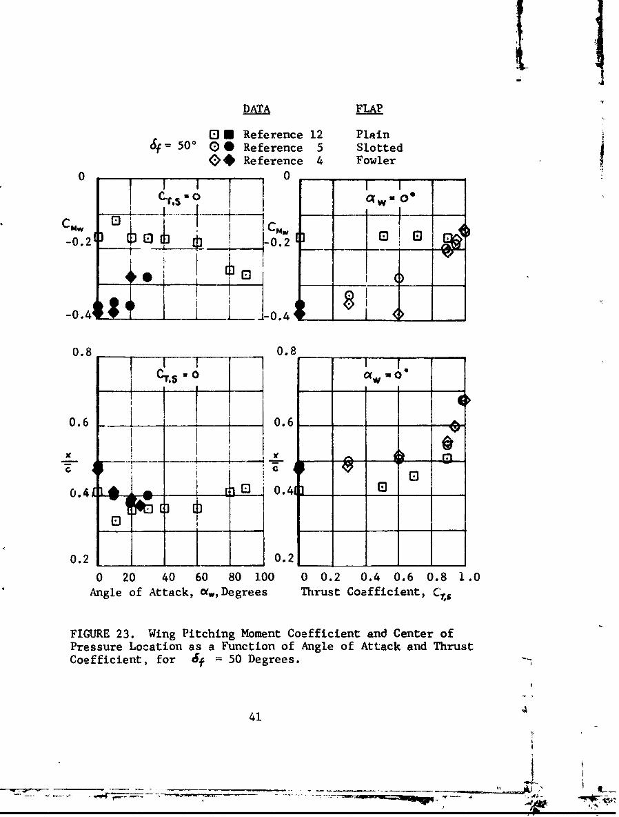
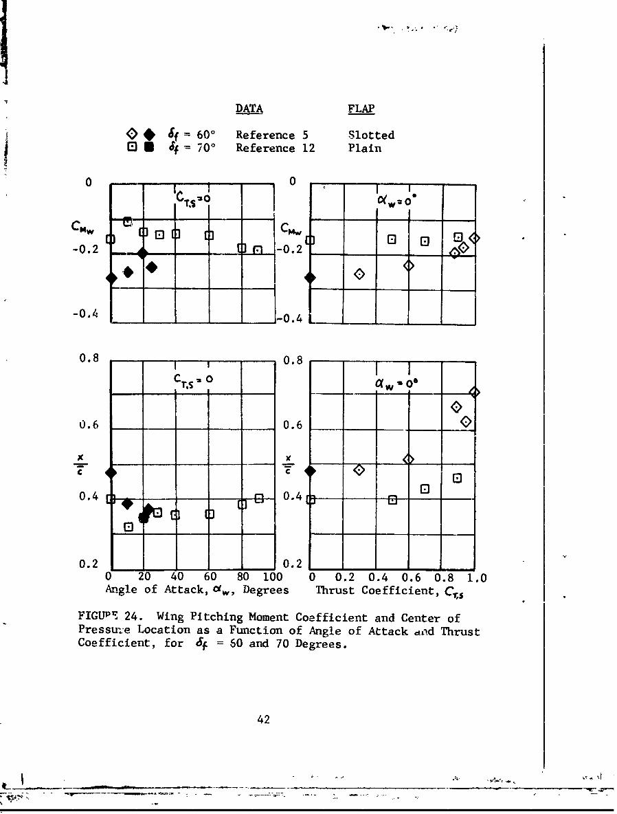
from 0 to 90 degrees and flap angles from 0 to 70 degrees.The data are presented versus fw a t Cs = 0, andversus Cis at dw = 0. Data are not presented f orsimultaneously nonzero values of C1 s and w , since nodirect measurements of the wing aerodynamic pitching moment Iwere made for these conditions.
From the data presented it can be concluded thatthe effects of Cis (which is a function of V. andVj ) on center of pressure location are small for values
of Crs between 0 and 0.8. However, the data for Cgs = 0show that the ce .ter of pressure location is affected byangle-of-attack changes. This implies that the data forCs = 0 are useful for approximating the center of pres-
sure location and wing pitching moments in the C,,,range from0 to 0.8. At values of Crs above 0.8, however, thereexists a sharp rearward shift in the center of pressurelocation to about the 70-percent chord point at CXS = 1.0.Due to the predominant thrust effect at high values ofC,& (corresponding to a low speed and high tilt angle
flight condition) the data from the C'w = 0, Cs>Ocurves may be used to approximate the actual center of pres-sure location and wing pitching moment.
The data also show that for models of the samegeometric characteristics (the models of References 4 and5) the Fowler and the slotted flaps produce equivalent wingpitching moments and center of pressure locations. The useof a plain flap results in lower negative values of CmNthan either the Fowler or the slotted flap. The effect ofthe slipstream (thrust) on the center of pressure locationis about the same for all flap types analyzed.
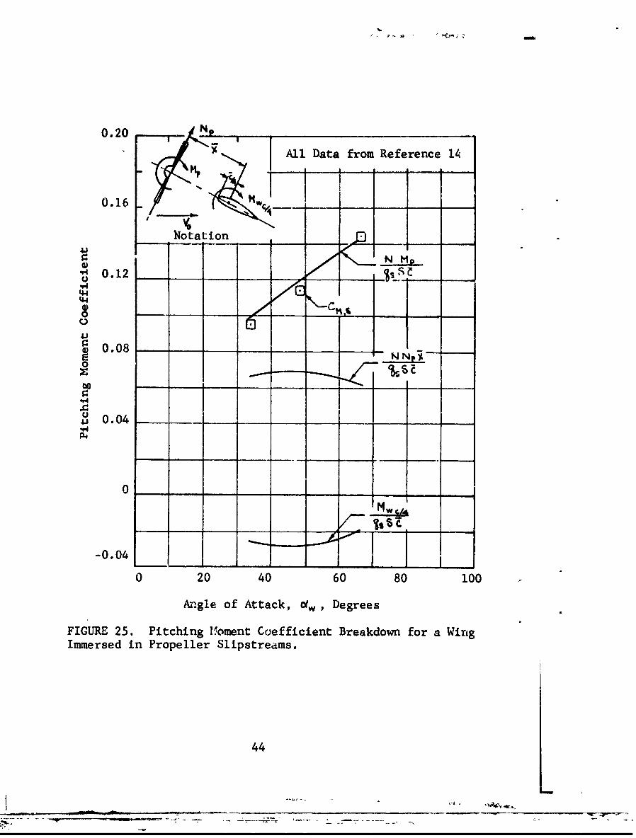
The rclative magnitude of the propeller and wingcontributions to the total pitching moment is obtained byexamining the data of Reference 14, which are reproducedin Figure 25. It is seen that for the specific conditionsillustrated, the magnitude of the propeller pitching momentis two to three times that of the wing.
43-. - _ _ _ -- - _ _ _ _ _ _ _ _ , - - - - - --- -- . _
'U. - ...- |
0.20 N I All Data from Reference 1i
0.16 MW-
-Notation
N MgGI __ __ __
S0.12 __SS
144
0'
S0.08
o .
0.04
,44
el-I
0
-0.04
0 20 40 60 80 100
Angle of Attack, dw , Degrees
FIGURE 25. Pitching 11oment Coefficient Breakdown for a WingImmersed in Propeller Slipstreams.
44
SLIPSTREAM EFFECT ON THE HORIZONTAL TAIL
Data.on the effects of propeller slipstreams on theflow in the vicinity of the horizontal tail of aircraft arepresented in References 15, 25, 26 and 27. The data ofReference 25 are found to be the most applicable to the caseof tilt-wing VTOL aircraft. These data are reproduced onFigures 26 and 27. Figure 26 presents the downwash angle atthe tail, C , as a function of Crs and c4, for severalvertical positions of the tail above the wing quarter-chordline. For C,;s = 0 the downwash angles are zero for loca-tions Z/c>O . These angles remain relatively small forvalues of Crs up to 0.6. For larger values of Crs ,i.e., where the slipstream effects are very large, the down-wash angle, C , increases rapidly with the angle of attack,Ofw . As noted in the figure, a downwash angle of 40
degrees occurs for some of these conditions.
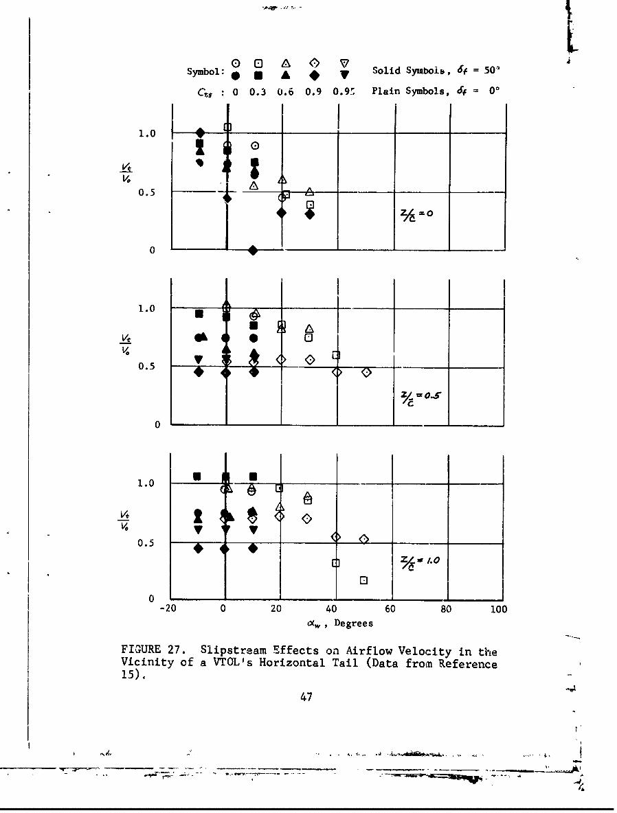
The effects of the slipstream on the velocities atthe tail, Vt , are presented in Figure 27. It may be notedthat in general Ve/Vo is less than unity. This impliesthat the tail is in a region of reduced dynamic pressure.The data indicate that an increase of slipstream velocity(an increase of C,, ) results in decrease of velocity atthe tail.
GROUND PROXIMITY
No general analytical method has been available forthe determination of the effect of ground proximity on theaerodynamic characteristics of a wing immersed in a slip-stream. However, a number of experimental investigationshave been performed on this subject, and the results ofthese tests are now discussed. As reported in References21, 22, and 28,buffeting, unsteadiness, and abrupt yawdisturbances were experienced during ground proximity testsof the Vertol V-76 aircraft. Similar results were obtainedfrom model tests as reported in Reference 18. In the latterreport, it is indicated that the unsteadiness tay be theresult of slipstream recirculation through the pro2eller.In general, the test data show that fuselage design has apronounced effect on hovering stability in ground effect.
45 ....
.. ~- - -- --- :~

Symbol: a A T * V Solid Symbols, 4f = 500
Cv-s 0 0.3 0.6 0.9 0.95 Plain Symbols, 4f = 00
40
00 ,
A&
0.
0
40
Co
20)
20
0
"60 80 100
"" w, DegreesI
FIGURE 26. Slipstream Effects on Wing Downwash Angle(Data from Reference 15).
46
LISymbol: * @ A # , Solid Symboi,, 6, 0 = .O
C,$,, 0 0.3 0.6 0.9 0.9ý Plain Symbols, 0f
1.0 I i-I_ _ _ _
0.5 6
Z4=0
0 1,
1.0
0.5
00
1.0
0.5 >
oc•, egree
[1i 3/6/.0
00
-20 0 20' 40' 60 810 100O(w, Degrees
FIGURE 27. Slipstream Effects on Airflow Velocity in theVicinity of a VTOL's Horizontal Tail (Data from Reference15).
47
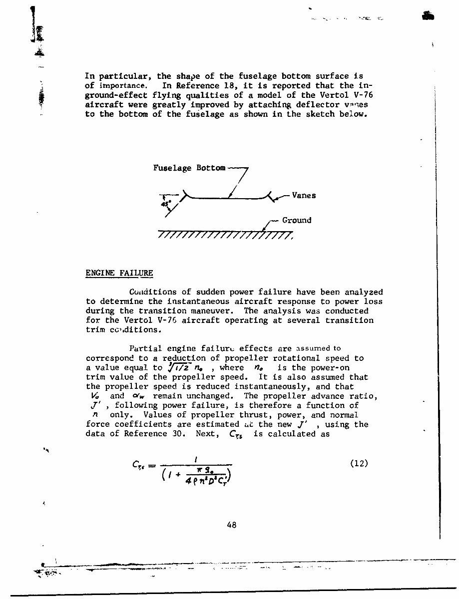
In particular, the shape of the fuselage bottom surface isof importance. In Reference 18, it is reported that the in-ground-effect flying qualities of a model of the Vertol V-76aircraft were greatly improved by attaching deflector v.nesto the bottom of the fuselage as shown in the sketch below.
Fuselage Bottom---7
Vanes
/ Ground
ENGINE FAILURE
Cuiiditions of sudden power failure have been analyzedto determine the instantaneous aircraft response to power lossduring the transition maneuver. The analysis was conductedfor the Vertol V-76 aircraft operating at several transitiontrim ccLditions.
Partial engine failurt.; effects are assumed tocorrespond to a reduction of propeller rotational speed toa value equal to Y77 nP. , where no is the power-ontrim value of the propeller speed. It is also assumed thatthe propeller speed is reduced instantaneously, and thatVL and 01w remain unchanged. The propeller advance ratio,
following power failure, is therefore a function ofn only. Values of propeller thrust, power, and normal
force coefficients are estimated 4t the new J' , using thedata of Reference 30. Next, Cr is calculated as
(12)
48
__________ -- - .----.-
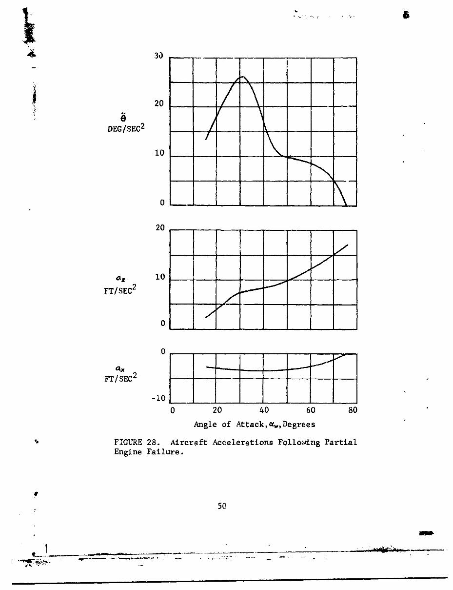
Theni the lift and longitudinal force coefficients are calcu-lated for the power failure condition. Wing pitching momentcoefficients, Cqs , which include nacelle and propeller con-tributions, are estimated from data of Reference 5. Thesecoefficients are utilized to determine the instantaneouschange from the trim values of the forces and moments actingon the aircraft. The resulting longitudinrl, normal, andpitching accelerations are presented in Figure 28. A changeof 912 of the normal acceleration occurs near the hoveringcondition. The maximum pitch acceleration (26 degrees persecond per second) occurs at IN'w = 30 degrees.
In addition to aircraft trim changes, power failurecan also cause the slipstream-immersed portion of the wingto stall. For example, before power failure, for a trim con-dition corresponding to 01w = 45 degrees, Cr$ = 0.74 andV.= 60 feet per second, Figure 10 shows that the slipstream-immersed portion of the wing is unstalled. However, followingpower failure, Crs decreases to 0.64, which results in a peakvalue of CQ -= 1.99. The corresponding C,,, is 1.55, andhence wing stall is resulted.
49
I.
S~3o
9! 20
DEG/SEC2 - - -
10
20
•=10 __ __-
FT/SEC2
0
0 I
axFT/SEC2
-10
0 20 40 60 80
Angle of Attack,c(, Degrees
FIGURE 28. Aircraft Accelerations Following PartialEngine Failure.
f
50
7 ~ -.-

SLIPSTRFAM EFFECTS ON VTOL AIRCRAFT STABILITY
The primaty objective of the analysis presentedin this section is te evaluate the use of propeller slip-streams tc augment the stability of a tilt-wing VTOL air-craft during transition. The stability analysis is conduc-ted for a four-propeller tilt-wing VTOL transport aircraftsimilar in configuration to the XC-142 Tri-Service VTOLaircraft. Details of this aircraft are shown in Figure 29and Table IV. The aircraft analyzed differs from the XC-142in that it employs a full-span Fowler flap and has a wingarea of 747 square feet when the flap is in the extendedposition. The analysis which is made for the longitudinaldegrees of freedom at transition airspeeds of 30 to 70knots is similar to that of References 31 and 32.
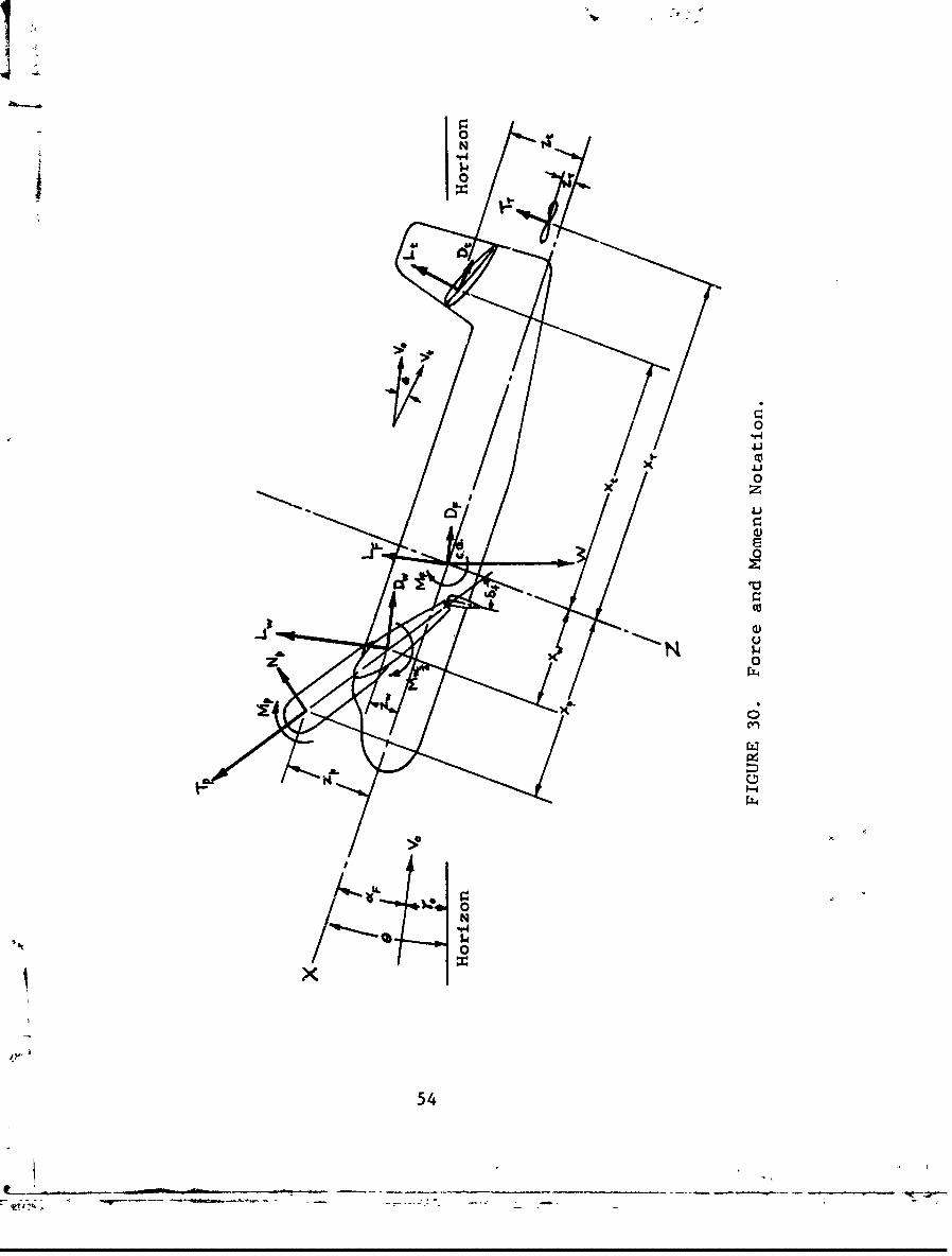
A body axes coordinate system is used in the analysis.The body axes system refers to a right-handed, orthogonalsystem of axes fixed at the aircraft center of gravity,rotating and translating with the aircraft. As shown inFigure 30, the X-axis is aligned along a reference line(datum line) fixed to the fuselage (positive pointingforward). The Z-axis is perpendicular to the X-axis,positive towards the bottom of the fuselage, and the Y-axisis mutually perpendicular to the X- and Z-axes.
EQUATIONS OF MOTION
The longitudinal equations of motion are asfollows:
z~~~~~~~~~ =[Lsni Dos][Lin•c - Dp coso.
+ [ L't s';n (o'( CO - ( os -
+ C05 -N(13)
51

U --.
/4I.i
0
U4
0
Q4-
0
"iaa
00
C~4
SI
52
it- - - -~ -, - - - -

TABLE IVVTOL TRANSPORT CHARACTERISTICS
FUSELAGE:Length, feet 50.0
WING:Area (flap retra..ted), square feet 535Area (flap extenled), square feet 747Span, feet 67.5Aspect ratio (flap retracted) 8.53Aspect ratio (flap extended) 6,42Mean aerodynamic chord (flhp retracted), feet 8.07Mean eerodynamic chord (fla, extended), feet 10.50Taper ratio 3.61Airfoil section NACA 4415
FLAP:Type FowlerChord, percent of wing chord 39Span Full
HORIZONTAL TAIL:Area, square feet 140Aspect ratio 5.68Span, feet 31.1Mean aerodynamic chord, feet 5.5Tail length, center of gravity to 0.25-max.,feet 25
PROPELLERS:Main: Number of blades 3
Diameter, feet 15.5
Tail: Number of blades 3Diameter, feet 8.0Moment arm, wing pivot to rotor center, 32.0feet
53
53
_ _ _ _ _ _ _ _ _ -i I
1V
0N t
"*140
*4J
4-i0z4JJ
0
54Z
Z Z=-[ LwcosOX+ DwSinO#]-[f coso~+DsycF
Z[P;siP-Y pjCos Lp;] +Wcose o9- (ý-i(14)
•M! Mw',/ +[LwCOsot" 4 D..sin0(j XW
- [Lwsiný'F - Dwcos 16' -z, ] +
-[L. Cos(0,c- 6) +rPtsin (CXF- 49)] xt TT X
N
-Z;TCos L*.-N/V'; Si",i] Z~j
TL j] x. - O+,.Z, 1; o (15)
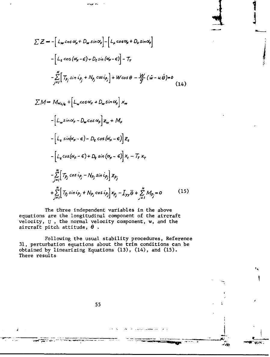
The three independent variables in the aboveequations are the longitudinal component of the aircraftvelocity, u , the normal velocity component, w, and theaircraft pitch attitude, e .
Following the usual stability procedures, Reference31, perturbation equations about the trim conditions can beobtained by linearizing Equations (13), (14), and (15).There results
5555
-j - 8
- --
-~---.* w ~ ~'-- -- -*q - - -

X U +X,:, + )(,w+. W +Xoý +X' o== o (16)
Zi"+ Za+Zww++ZO e +Zoe , 0 (17)
Muu + A44 + Mww + M ,ý + 19e + M6 + Mi j 0 (18)
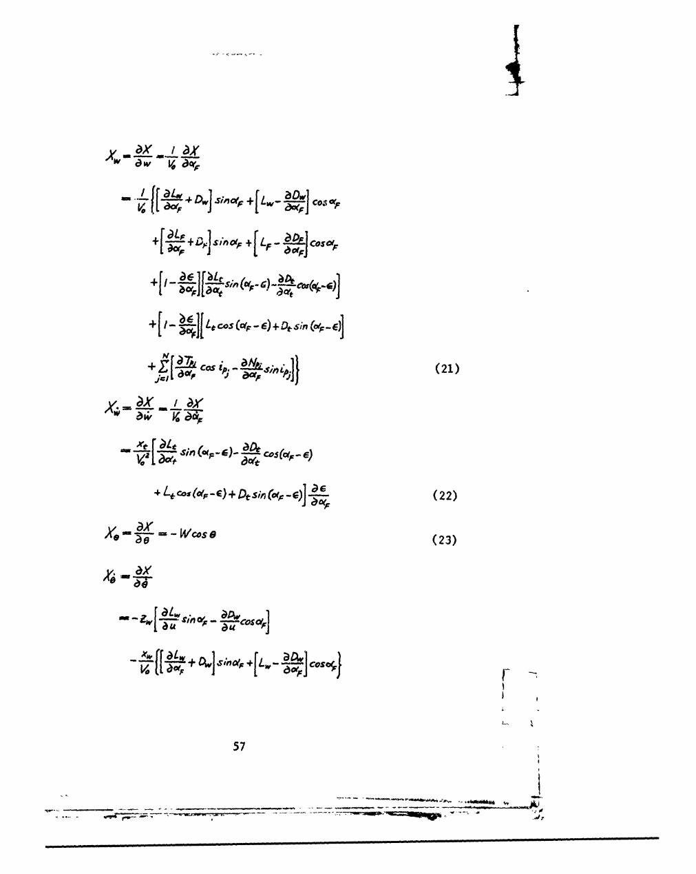
In Equations (16), (17), and (18), u, w, and 0now represent perturbation variables; i.e., u is the changeof the longitudinal component of velocity from the equilib-rium value, etc. Also, XV, Zu, etc., are the total sta-bility derivatives; that is, X = dX/au, Zu =a Z/6u. Thesederivativw3, which are evaluated at the trim conditions,are obtained by performing the appropriate partial dif-ferentiation of Equations (13), (14), and (15).
The total stability derivatives are:
xux
xU dx
_ cos - e) +iO (19)
Y W -(20)
56
4)4-i (01we GO-i cofsc'rIi~
Cos ~ Cso~
Xti.+fL-
r ~0 1
(22)
T Wose(23
57
+ Cos (CF-OE) +O (tce]
-ZjLJ 2Cos~.. I;.
+j [ c .sc,1 -" 'Pns"ý
T (24)
Zi- r
Cos (25) +ýA
!ý7r' IV C Cos(25)
58
+ Xx+D]COS(e)+ W (28)c)
si (a -c) (29) (F
+ T, +
+~f[~~c~w +COa'.V4Losj,
59e, ;EIa-4~F(7
/ ý
a,;v Va -____
Vo0
4-0-D
*~~ [Cos(-Ej
Xt (cae )
net0- ~(*e c
-4 Srn (OfC -. ) + tC s( t 0
jer )
MuAm
+ do~c~c ) u si&f-e)
M. cM~Z7 -
Af ;)Af, c)Aofw.* aA .+r aTr
C~a (32)
gxw a
-Afl
1+ 1,
Xe6 fr1 ŽC.1[ r 1O(g-)
t~~~~~~~~D ci ~I~tCSOp -s sm(a,;)
/ _ _d fCOS i a ul p . p
OAl
61 -
M4 )W.a 7 T07
+t 4 -- s;,, ( -E) - tcsu (of-c
VI'
Lt)]+ (34)
M. - 0 (35)
++ D J $mic -4 +] w e osce4
4 -wDwcos¶..r ~j£h~
62
it_ _ __ _ _ _

** 4 Cal (avg -. e) tD, sio (tee - )
-4Isin (*..c) +Dtcos(4- coJ
aXTUr
Al~Colh COI, 'Sirj
j __ .
+ INV~ 36
I (os)
Usin teasnpi S hAil
.- 0 P'. a0
1363
Usin th assmptollstha

the total stability derivatives bezome
__-T- (39)
x4-/ ao;-w '50e
sig __ 'Os -1
+E (40)
L~Lar (41)
K.r-We 6 (42)
Aax
urnsv +---1 - + sine~4 L)6 -L tW-g ao( I
64
"V ( Odc~J (43)
alA
j=I (44)
Z CIZM 0(45)
C)IV - + 1.j..
a,~ a (F~ AV] ()-0
.aC4
Z17- f 7,p
65l
---- -- - - -- - - - - - _ _ _ _ - - - -*..~er (46)-- -
ZD~jU3-W iAG(48)
Aý - rw +Du+ ~Cos 6
ju' V. Y~f DW
.gasijjn 0. + a~f Cos5,(49)
MI '
ma u
+4~~4±sin~~+ X~c~EJK+__
6166
WO - +S..
5'-50

M4 '51)
-. 01
_C.,
w . C)-I
+A~t S~n + cs- - I t Csl 61
=CSO - Sofl +0V. V,~
- ,N+~m[,a 7ev ()
4=; (54) fF0 .
672
-. - -- -___________________ -________,_4
I~ ID .16 ar
+XE[LZ S -V LSin
+W ~cS41~Jn + 4D-cs CsiJ
I C) a a"
+ Cosvq + 55Vo aoul
~-V--- . - -) -F aa

INCORPORATION OF SLIPSTREAM EFFECTS INTO THE VTOL STABILITYDERIVATIVES
The derivatives Xu, Zu, Mu, etc., defined in thepreceding section consist of contributions from propellerforces and moments, wing forces and moments, and horizontaltail and tail rotor forces. The methods used to determinethe contributions of each of these items to the derivativesare now discussed.
Wing Derivatives
The wing X and Z stability derivatives are estimatedby using the lift and drag analysis of Reference 3 forwings immersed in slipstreams. The wing moment derivativesare estimated from the test data of Reference 15.
The slipstream lift and drag analysis is summarizedby the following equations. Wing lift and drag are expressedas
Lw= Ciw TsS (57)
and
Dw= Cw 2s .S (58)
The lift and drag coefficients,CLw and CDw , based onslipstream dynamic pressure, are
C =-(- Crs) aav + 3.74 (1 -,A%2)(!NADE % ~ cs-#
9(59)
s Ds
69
+ 3. U Si')r- Si,(O,-4I) (60)
The wing stability derivatives can be obtainedby differentiating Equations (59) and (60) with respectto u and 9, . Since
= ,.,, = =,
there follows
+ 3.7 (A D,
-,a) Rr 0Cos(
+ (e-Le' (t.9 4 rs;c I (Olp )
- 2cA ,u a,- OI(1
-- r,) (, S/l (01p )
70
-v.-.... -. ... .. . .. * " - -

-4p-
-" f. s ( ap -4 ,)
r 2 N-c)'"r' ýLC A (6
+_ 2N c Cr .ý Co + r Vs LA
- 120-t84 au
_
--
4 0
-,.Ae (-n) 5a I
71 •

+ 3 .74 t A2 Cos&~,#
+ r
ml A&j cosop#
-2~c rs a ft sin (
+.L2C5 D
II
t4~+ ~ 0- )cosa# (63)
72
~C~w w
s "Ncrs O/
+ 2NCrs1C a -O(ty~f )ri
acr~ aoc
21c , LJ co~e-) cos01dp-#
+ S7 , aSin
5L 0
__ ~ rs# C((at,)
+ t3A2[ 11T(q~sO73 4o~e
~s~p+ 2 cs~-fz----
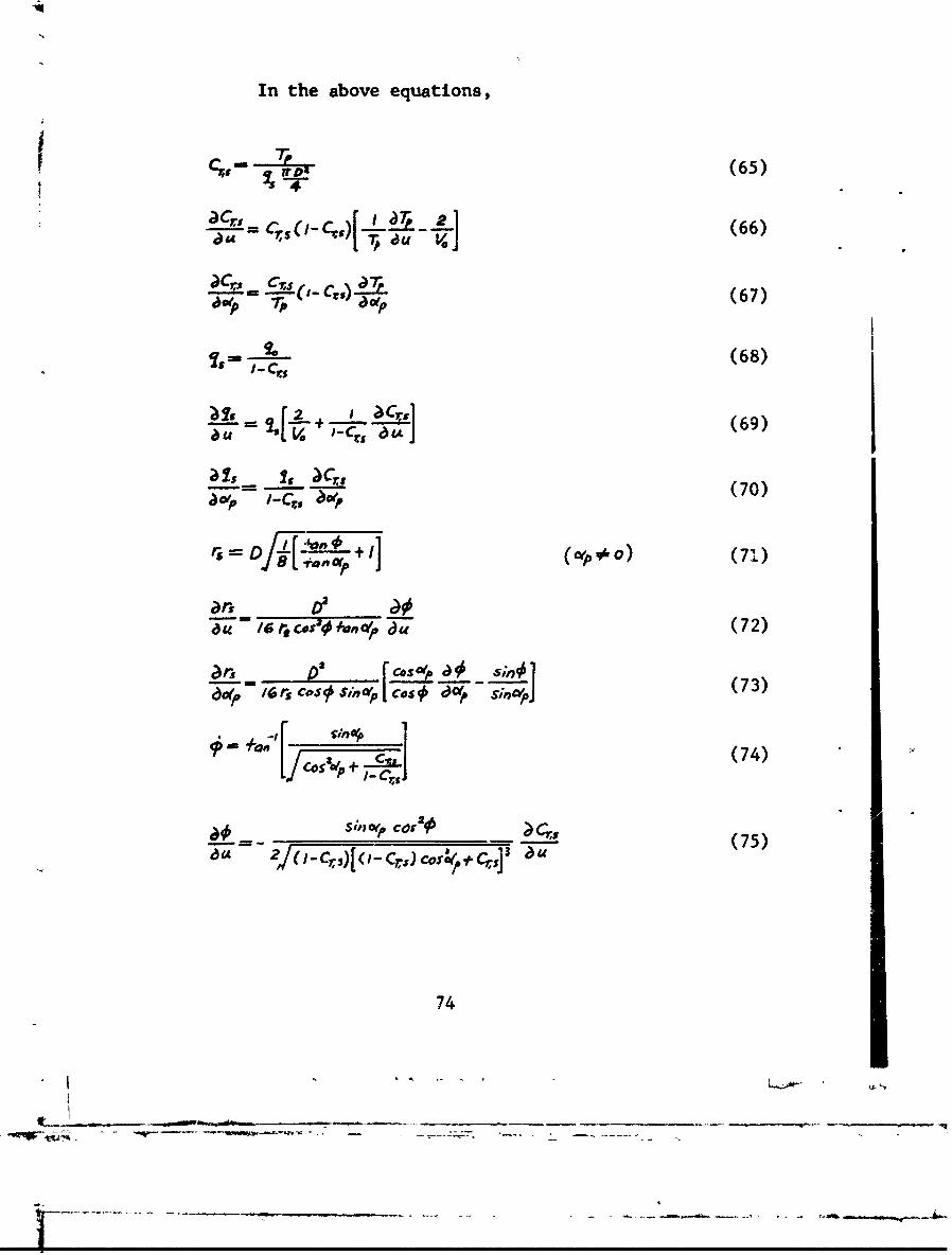
In the above equations,
TC-- TAP (65)
e--n- = 5 (C."[ T A (66)
a•' C,3 a~ (67)
•' (68)
-('2 •.+,_r (69)
is s J4
____ " ~ '••d (70)
=,r -
C-'" /s7['Vpr# +1 au 0] (71)
(72
0 r .-V . C r. S C ") 1
qoc~"? (75)IT- C6
2s[ 2 cl 74
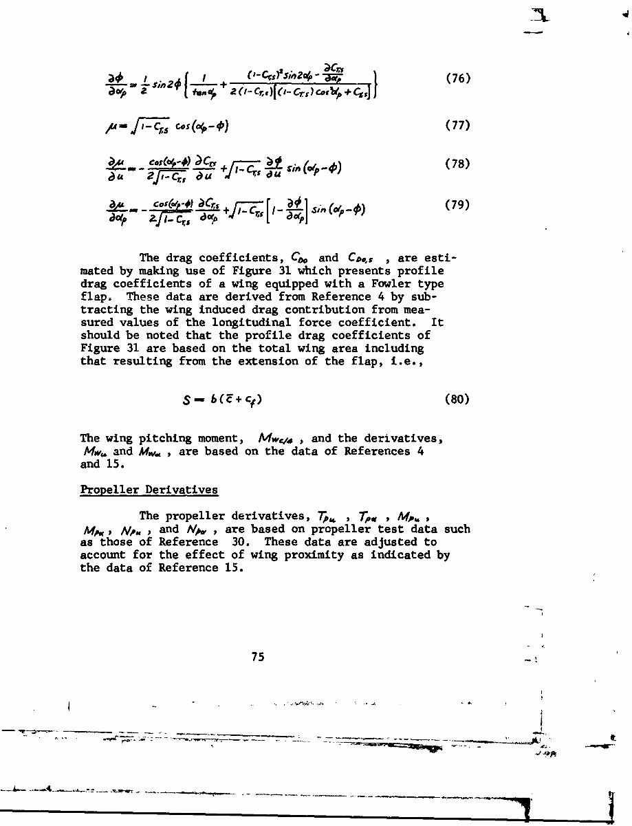
__ sin2f + 'C.)SnC1W-P_ (76)
r1_- _C [os 0 - (77)
aol" ajT U
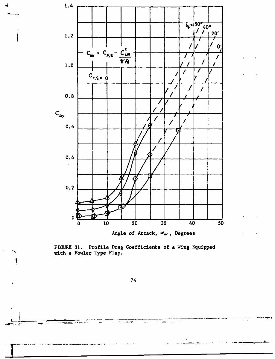
The drag coefficients, Co and Co.,o are esti-mated by making use of Figure 31 which presents profiledrag coefficients of a wing equipped with a Fowler typeflap. These data are derived from Reference 4 by sub-tracting the wing induced drag contribution from mea-sured values of the longitudinal force coefficient. Itshould be noted that the profile drag coefficients ofFigure 31 are based on the total wing area includingthat resulting from the extension of the flap, i.e.,
S - 6(E+ C) (80)
The wing pitching moment, Mwqa , and the derivatives,Mw. and Mw., , are based on the data of References 4
and 15.
Propeller Derivatives
The propeller derivatives, T , A,Af, N,* , and A/• , are based on propeller test data such
as those of Reference 30. These data are adjusted toaccount for the effect of wing proximity as indicated bythe data of Reference 15.
75 -
- ,,.,- 7•'-•' - --• - -- - - - ------,.. .. ...-_. . -•- - - --.. .-- -
-- - - _________m__--_--__L
1.4-~ 1~1.2 I 200
COO- CXs - CLW" / "
1.0 C's [ /11t/CTS -0/ /
0.8 J_
0.6
0.2 - -
0 10 20 30 40 50
Angle of Attack, 01, Degrees
FIGURE 31. Profile Drag Coefficients of a Wing Equipped"with a Fowler Type Flap.
76
-

Horizontal Tail Derivatives
The inmerical evaluation of the horizontal tailderivatives is based on the data of Reference 15. Thesedata are reproduced, in part, as Figures 26 and 27. Tailrotor derivatives are obtained from the data of Reference29 using a tail rotor advance ratio and a tail rotor angleof attack, based on values of C and 14 from Reference 15.In the analysis, consideration was given to the fact that at30 knots control moments are generated by means of a hori-zontal tail rotor, and at 70 knots by means of a horizon-tal tail surface.
Slipstream Stabilizer Derivatives
From Equation (5) it is seen that the angle ofattack in the slipstream, o, , is affected by flap deflec-tion, df . It follows that the lift and drag derivativesof the wing can be readily varied provided ýhat a meansfor changing cs is incorporated into the aircraft controlsystem. Accordingly, the use of a wing trailing-edgeflap for stability augmentation is investigated. Thegeneral flap stabilizer characteristics are described bythe following equation:
kJ+kGe+k. + +kww. o (81)
Equation (81) includes pitch attitude and rate feedback,k,e + kg6 , and vertical velocity feedback, kI.
The appropriate stabilizer derivatives for the three air-craft equations of motion are:
. _Lr Z= (82)
- /-- -_L-W (83)
Sas- xYY asas -b &W] (84)
77
77

Values of c)L..4fS , IbDwfJ)c and aM/I6 are obtained from
the test data of Reference 12.
NEWRCAL YALUr'S OF DERIVATIVES
The trim conditions for 30 and 60 knots are asfollows:
Crs = 0.9275cOw = OP = 40 degrees4+i = 50 degreesW = 35,288 poundsr. = -650 pounds (forZMc-y.= 0)C,, = 0.516C,. = 0.718Ca = 1.22C ,,As = 0.15
Ca = 0.35vw = Ofp = 8 degreesdf = 50 degreesW = 34,200 poundsLe = -2070 pounds (forZAen.= 0)CLW = 1.85Co = 0.313Co = 0.13C,,s = 0.11
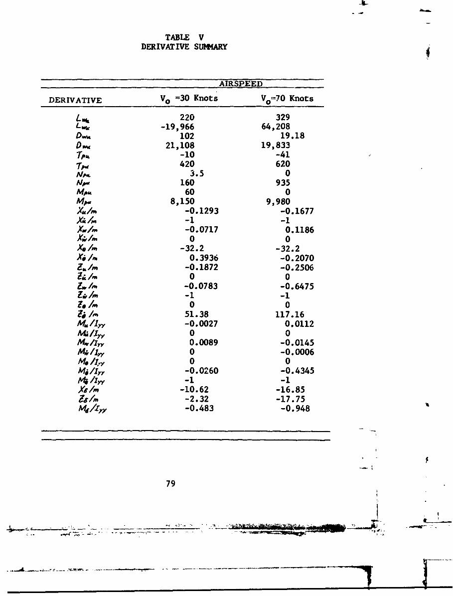
The numerical values of the derivatives are sumnmrizedin Table V.
78
- -------
I l mm m l mi n l - .
-Lit
TABLE VDERIVATIVE SUMARY
AIRSPEED
DERIVATIVE VO =30 Knots Vo=70 Knots
/.mý 220 329L ,a -19,966 64,208Dw, 102 19.18D ,, 21,108 19,8331 pAt -10 -41T". 420 620NP,, 3.5 0ANP. 160 935M,,, 60 0mow 8,150 9,980Xm /m -0.1293 -0.1677A /M -1 -1
/,,. -0.0717 0.11860 0
Xe/rn -32.2 -32.2Xi/f, 0.3936 -0.2070z,./0 -0.1872 -0.2506
& n0 0t_ /1% -0.0783 -0.6475Z&/M -1 -1Lis/r" 0 04 /rn 51.38 117.16/Am /lXY -0.0027 0.0112At /Iy, 0 0Mw/Iyy 0.0089 -0.0145S/In, 0 -0.0006Af/ 1,, 0 0Mi/lyy -0.0260 -0.4345A l,-1 -1As/,n -10.62 -16.85& /1 -2.32 -17.75M/r/, -0.483 -0.948
79
- -w--
- - ------------ *-~-- - - -- - ---
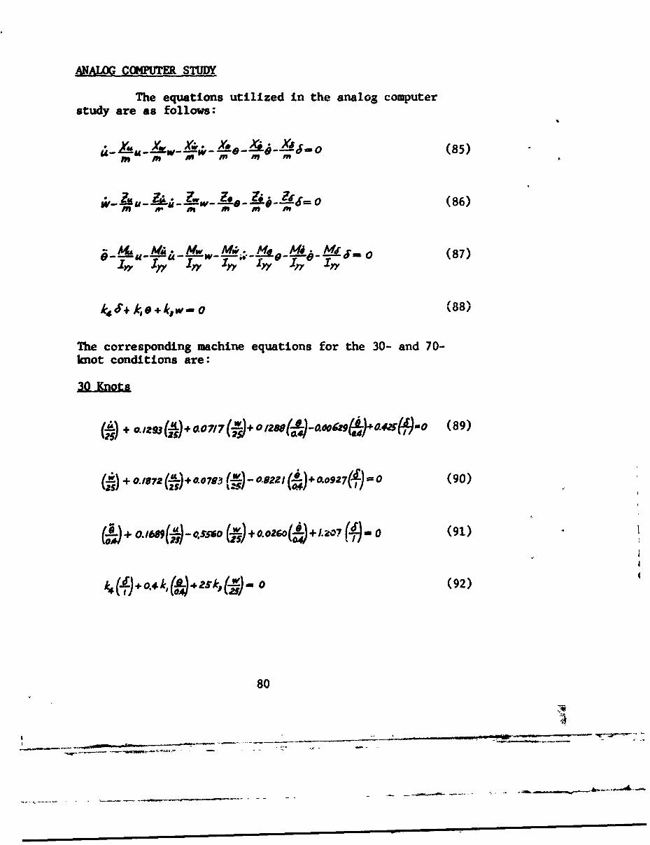
ANALOG COMPUTER STUDY
The equations utilized in the analog computerstudy are as follows:
S W -W-, 49- ,YO u-i. -L o (85)
Z. , .... _,,= (86)- A- Mf' 49
e___A4_M__A Mw Me_• "k4. .i 0'•• (87)
•,, Y -r7Y I,• IYv 1 0-" I -YY
k4S+ kO +kw- o (88)
The corresponding machine equations for the 30- and 70-knot conditions are:
(•,) + oa,2,,(•,)o 0.07/7 0 ( 2Bo(80 O.OQ9 V,441(,-)NO (89)
Ci¶) +0.,,72(jj÷+O7oU , )-.o.ua2I ÷ O.oaT•)=O (90)
+0307 + 0 .0o,27MA)+ 0. 16 0. A5 756O0 (~+0.0260(i+1.207 (#) 0 (91)
k4 +o4k0 (92)
80
- '- - . .... - --.--.- N
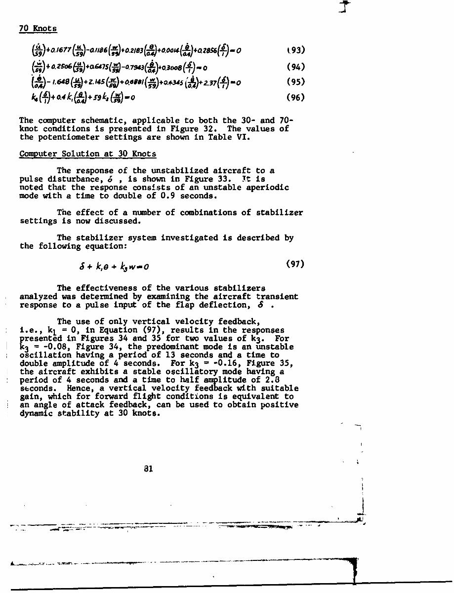
70 Knots
N )+oI677" ('Lo~all$(.ý).o.21e3 +0- a0014
( ,,)+O.Z~o6 )*7S(7-o.7M a%+ 031"(*)-.o (94)
( I -. 649 *+Z. 145(g+0010B ()+.4 )+2.37() 0o (95)f S1)+ 0.4 k,(f'A"•+ rqk, (1-W)"Wo(6
The computer schematic, applicable to both the 30- and 70-knot conditions is presented in Figure 32. The values ofthe potentiometer settings are shown in Table VI.
Computer Solution at 30 Knots
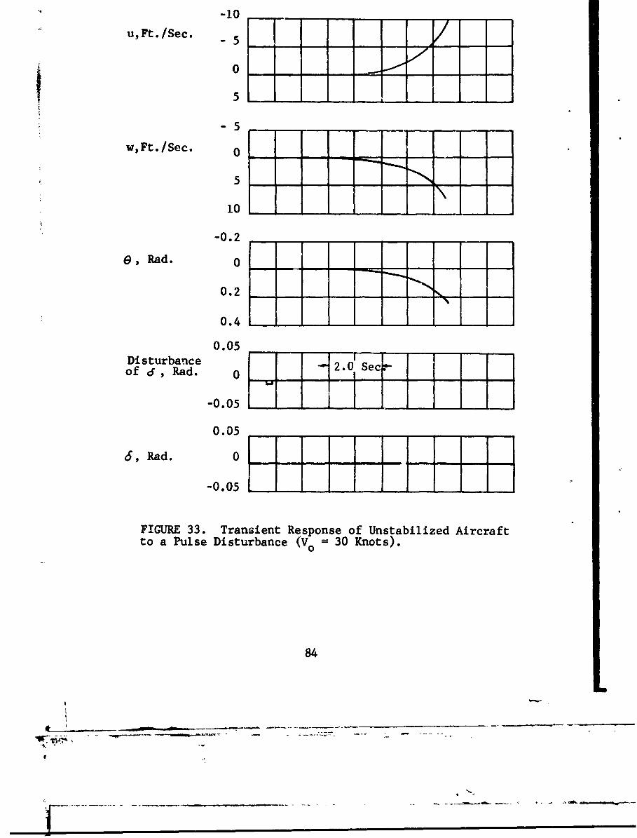
The response of the unstabilized aircraft to apulse disturbance, 6 , is shown in Figure 33. Yt isnoted that the response consists of an unstable aperiodicmode with a time to double of 0.9 seconds.
The effect of a number of combinations of stabilizersettings is now discussed.
The stabilizer system investigated is described bythe following equation:
J + k,e k/w-O (97)
The effectiveness of the various stabilizersanalyzed was determined by examining the aircraft transientresponse to a pulse input of the flap deflection, 6
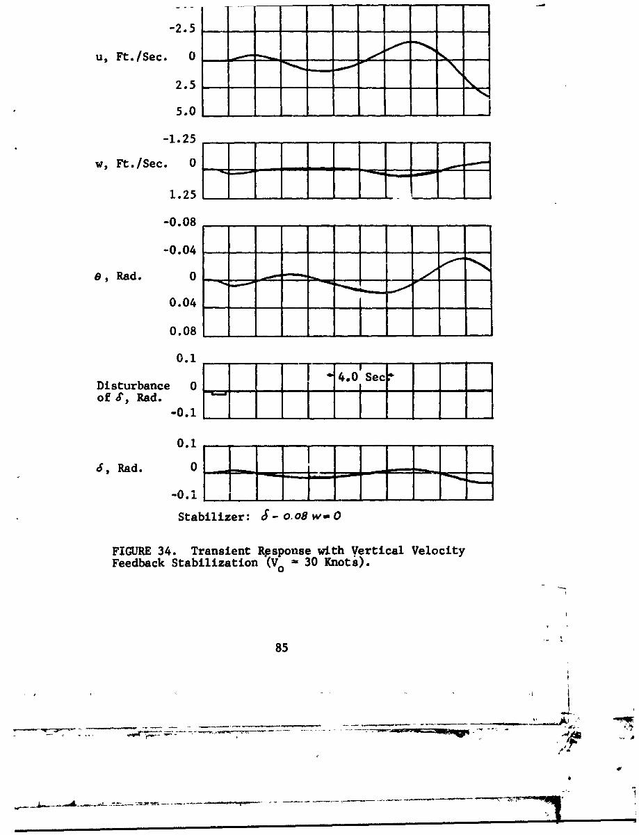
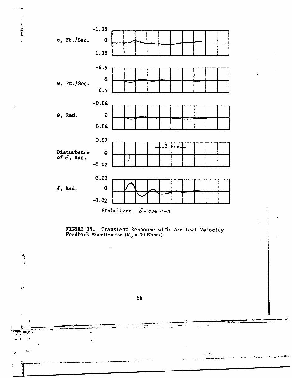
The use of only vertical velocity feedback,i.e., k1 = 0, in Equation (97), results in the responsespresented in Figures 34 and 35 for two values of k 3 . Fork3 = -0.08, Figure 34, the predominant mode is an unstableoscillation having a period of 13 seconds and a time todouble amplitude of 4 seconds. For k 3 = -0.16, Figure 35,the aircraft exhibits a stable oscillatory mode having aperiod of 4 seconds and a time to half amplitude of 2.8seconds. Hence, a vertical velocity feedback with suitablegain, which for forward flight conditions is equivalent toan angle of attack feedback, can be used to obtain positivedynamic stability at 30 knots.
81
_____I

00
0
41: - -- - - - I-
0)
.-I
, V
U
0
)a
S . . . .. ..
L4-
C4)
i E .43 , cl
io mmm 82 m

TABLE VIANALOG COMPUTER POTENTIOMETER SETTINGS
FOR VTOL LONGITUDINAL STABILITY ANALYSIS(WITHOUT STABILIZER)
POTENTIOMETER POTENTIOMETER SETTING*NUMBER 30-Knot Airspeed 70-Knot Airspeed
2 QO0 0.7170 0POl 0.1293 0.1677
Q01 0.0629 0P 0 2 0.5152 0.2183
Q02 0.1000 0.1000
Q0 3 0 0.1186Q04 0 0.0014P 0 5 0.1689 0
Q05 0.5560 0P0 7 0 0.2145
Q07 0 0.1648P0 8 0.0260 0.4345
Q0 8 0 0.0881P1 3 0.0100 0.0100P 18 0.1207 0.2370P
19 0.0927 0.3008
Q1 9 0.0425 0.0286P21 0.8221 0.7943
Q21 0.0783 0.6475Q22 0.1872 0.2506
*The remaining potentiometers shown in Figure 32 were
used to simulate the stabilizer or for static check.Hence, they were set at zero for the unstabilized flightconditions.
83
• -10
u,Ft./Sec. 5
0_-5
-5
w, Ft./Sec. 0
5 117E
10
-0.2
e, Rad. 0
0.2 ___
0.4
0.05Disturbance 2.0 Secof 6, Rad. 0 1
-0.05 _
0.05
6, ad. 0
-0.05 ...
FIGURE 33. Transient Response of Unstabilized Aircraftto a Pulse Disturbance (Vo 30 Knots).
84
- - -- ~-
Si Im-
-2.5 ..
u , Ft ./Sec. 0 ",-- N
2.5
5.0 _
-1.25
w, Ft./Sec. 0
1.25E i
-0.08
-0.04
a, Rad. 0
0.04 "1_
0.08
0.1 iii * 4,0 Sec" ii
Disturbance 0 , 0 ,, -
of S', Rad. -0 -1_0.1
0.1
J, Rad. 0
-0.1
Stabilizer: 6- 0.08w-O
FIGURE 34. Transient Response with Vertical VelocityFeedback Stabilization (Vo = 30 Knots).
85
--- -- I !
uF.Ie.-1.25 F.•: ~ ~ U, ./Sec. 0 -.
1.25 E-0 .5 - . ..-.... .
w, Ft./Sec. 0 J -h h -
0.5
-0.04 .....
e, Rad. 0
0.04
0.02
Disturbance 0 0jIj 4 H Ho f d -,, R a d . _0 .0
-0.02
d'. Rad. 0
-0.02
Stabilizer: 6- o.16 w.O
FIGURE 35. Transient Response with Vertical VelocityFeedback Stabilization (Vo = 30 Knots).
86
iL --- ----
'40.
f , %A
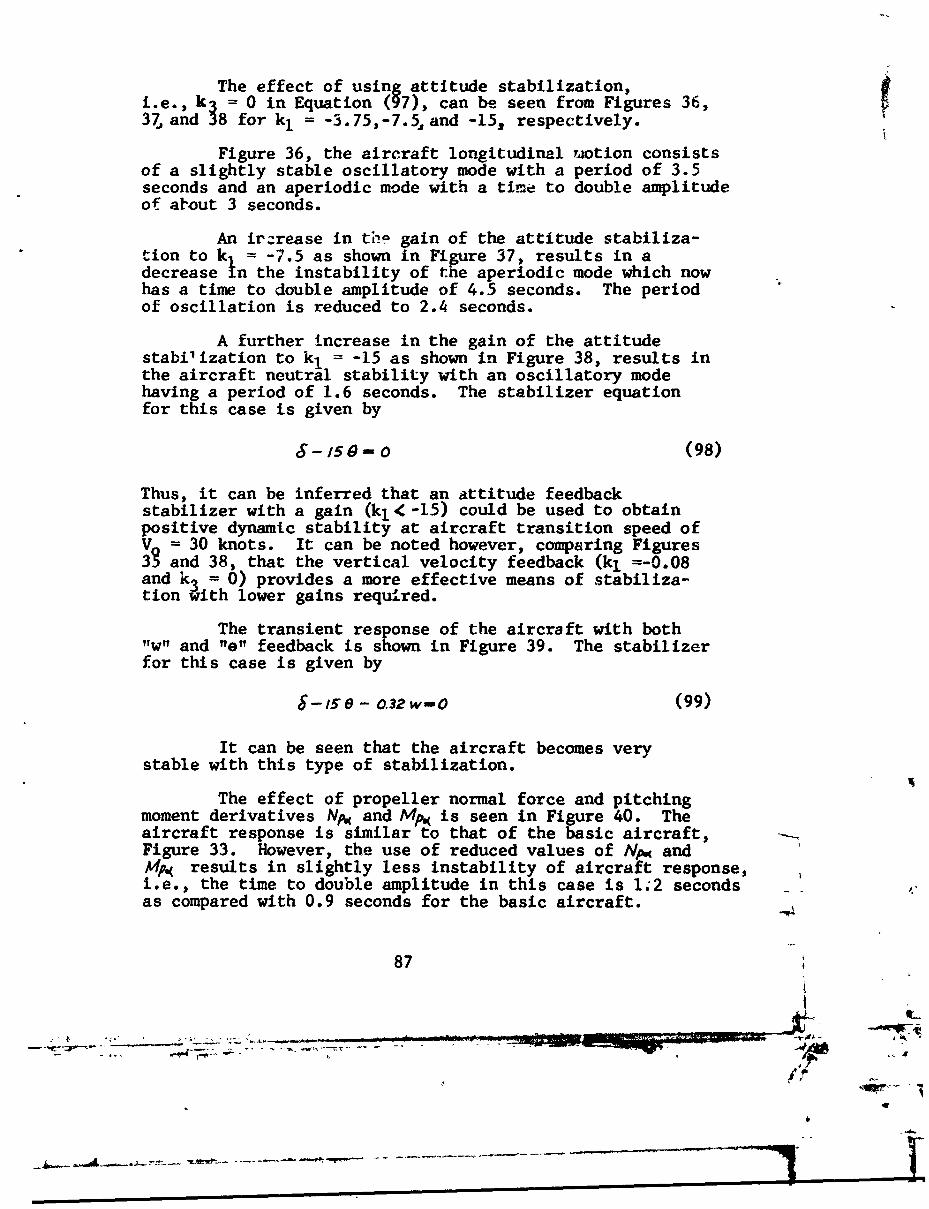
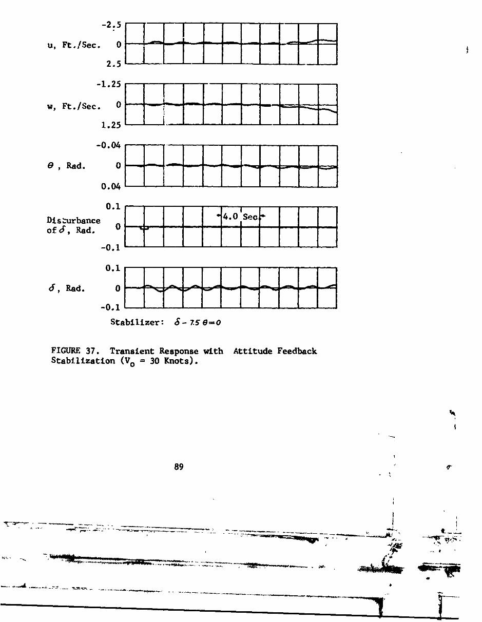
The effect of using attitude stabilization,i.e., k 0 in Equation (97), can bee seen from Figures 36,37 ;2 38 for k, = -3.75,-7.5, and -15, respectively.
Figure 36, the aircraft longitudinal TAotion consistsof a slightly stable oscillatory mode with a period of 3.5seconds and an aperiodic mode with a time to double amplitudeof ahout 3 seconds.
An ir-rease in thie gain of the attitude stabiliza-tion to k = -7.5 as shown in Figure 37, results in adecrease In the instability of the aperiodic mode which nowhas a time to double amplitude of 4.5 seconds. The periodof oscillation is reduced to 2.4 seconds.
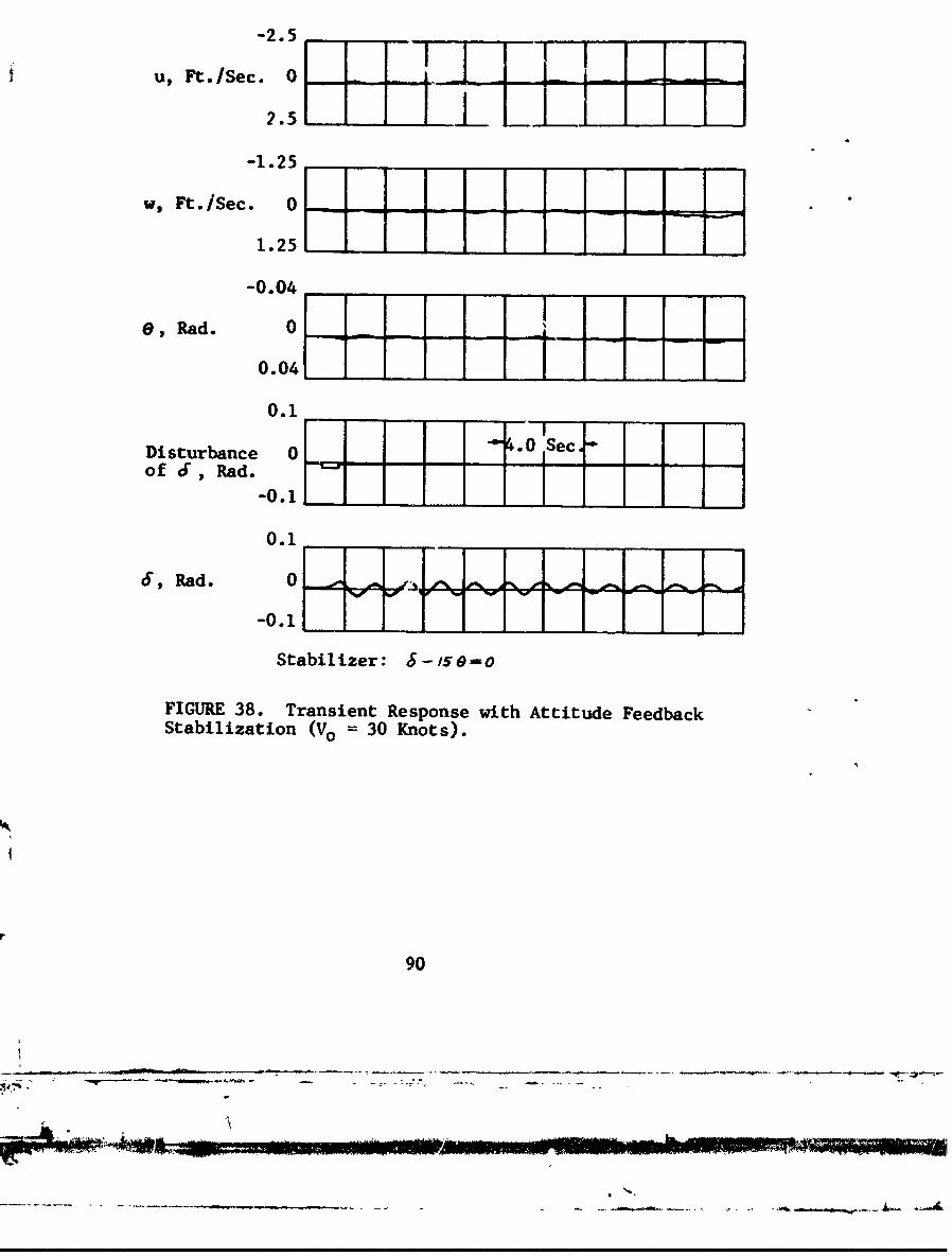
A further increase in the gain of the attitudestabilization to k, = -15 as shown in Figure 38, results inthe aircraft neutral stability with an oscillatory modehaving a period of 1.6 seconds. The stabilizer equationfor this case is given by
S-/50-o (98)
Thus, it can be inferred that an attitude feedbackstabilizer with a gain (kl<-15) could be used to obtainpositive dynamic stability at aircraft transition speed ofV= 30 knots. It can be noted however, comparing Figures
and 38, that the vertical velocity feedback (k1 =-0.08and k3 = 0) provides a more effective means of stabiliza-tion with lower gains required.
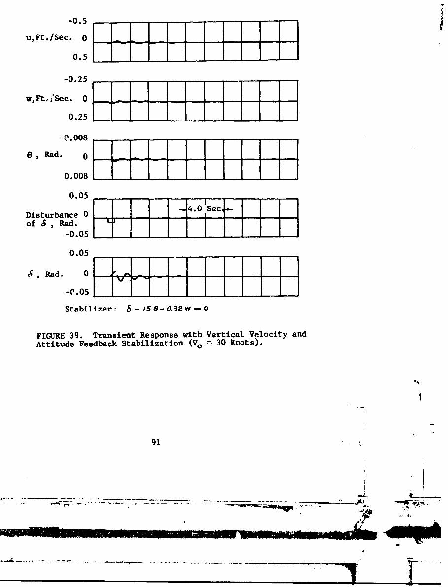
The transient response of the aircraft with both"w" and "e" feedback is shown in Figure 39. The stabilizerfor this case is given by
8-15" - 0.32 w-0 (99)
It can be seen that the aircraft becomes verystable with this type of stabilization.
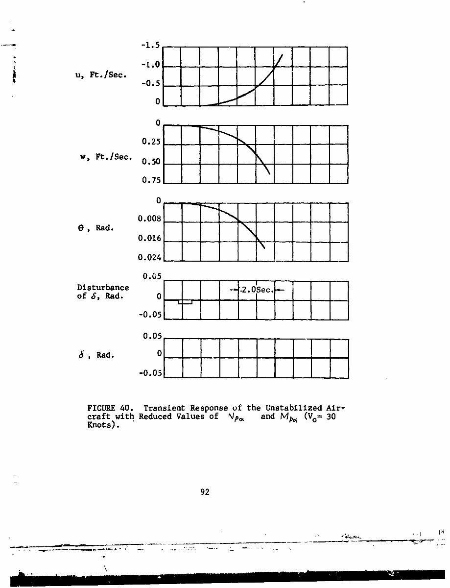
The effect of propeller normal force and pitchingmoment derivatives NpW and A4p. is seen in Figure 40. Theaircraft response is similar to that of the basic aircraft,Figure 33. However, the use of reduced values of Np.( andA,/p.( results in slightly less instability of aircraft response,i.e., the time to double amplitude in this case is 1.2 secondsas compared with 0.9 seconds for the basic aircraft.
87
a o-
-4l,
*0

-5.0.-
U. Ft./Sec. 0
-2.5 -
w, Ft. /Sec. 0 --S2. 5I - II
a, . Id. 0-0.041
-0.1..-- ~
Disturbance oL #. Sec, Iof 6, Rad. -
0.04
-0.i
Stabilizer: 6f-37549=0O
FIGURE 36. Transient Response with Attitude FeedbackStabilization (V0 30 Knot~s).
Il
.0.
-2.5
u, Ft. /Sec. 0----
2.5SoI - F -! -!- 'i- - -F
-1.25
w, Ft. /Sec. 0 m j j71.25 --
-0.04
1 , Rad. 0 -- ---
0.04 d10.1 -4.0 See
Disturbance 10of 6, Rad. 0 -i
-0.1
0.1
6, Rad. 0 m .. ..
-0.1
Stabilizer: S- 750-=0
FIGURE 37. Transient Response with Attitude FeedbackStabilization (Vo = 30 Knots).
89
- -1
-~- ~Z~~rz------ t_
-2.5
u, Ft.ISec.0 0iiL- I
2.5H . I-1.25
WS Ft. /Sec. 0il
1.251
-0.04
0, Rad. 0
0 . 04
0.1
Disturbance 0 4.0 1Secof 6, Rad.
0.1
6f, Rad.0
Stabilizer: 5-l5s--o
FIGURE 38. Transient Response with Attitude FeedbackStabilization (Vo 30 Knots).
90
iWO
-0.5
u, Ft.ISec. 0 _-.
0.5
-0.25
w,Ft:,iSec. 0 --- Poo
0.25
-CI.008
,I-ad. 0 j- -=--
0.008
0.05i0 .05 4.0 Sec .
Disturbance 0 -- tecof 6 , Rad.
-0.05
0.05
R• ad. 0 •••• ,,•-
-0.05
Stabilizer: 1 - 5- o032 w - o
FIGURE 39. Transient Response with Vertical Velocity andAttitude Feedback Stabilization (Vo 30 Knots).
91
I I WON4t -
---- I-1 .5
-1.0A u, Ft./Sec. -0.5
0
0.25
w, Ft./Sec. 0.50
0.75
0
0.008 .. _e, Rad.
0.016 __
0.024 __1
0.05Disturbance 2.OSec. -
of 6, Rad. 0 -
-0.05
0.05
c, Rad. 0
-0.051 1
FIGURE 40. Transient Response of the Unstabilized Air-craft with Reduced Values of Np= and Mp, (Vo= 30Knots).
92
il•: ',' i II i• i . • : .] I I I l i • I 'II ! -- I I ' ! ! ! ! ! i ! ! !• I i i i ;
-I I I I I l l a II I I I I II I I -x , , , , , ,

Computer Solution at 70 Knots
The basic, unstabilized, aircraft response toa pulse disturbanceý is shown in Figure 41. As expected,the response for this flight condition is similar tothat of a typical fixed-wing aircraft. The aircraftresponse consists of a long period oscillation (phugoidmode) with a period of 10 seconds and a time to halfamplitude of 9 seconds.
The use of a stabilizer corresponding to
8- 150 - o.16g w-o (100)
results in the response shown in Figure 42. As notedfrom this Figure, the response is very rapid and stable.
Correlation with Experimental Data
The calculations made herein can be compared onlyqualitatively with existing test data. Available data,such as those of Reference 17, and still unpublished dataobtaived from the Princeton University long track facility,are for model aircraft with scaled-up gross weights andmoments of inertia which substantially exceed the designvalues utilized herein. However, the trend shown in thepresent calculations agrees with the experimental data, inthat the instability exhibited at low speeds is graduallyreduced as che speed increases.
Conclusions
From the above analog computer study, it may beconcluded that propeller slipstream can be used to augmentthe dynamic stability of a tilt-wing VTOL aircraft through-out the entire transition flight regime. This includesthe hovering condition as reported in Reference 3. It isnoted that a combination of attitude and angle-of-attackfeedback results in stable responses both at 30 and 70knots.
93
S_; e
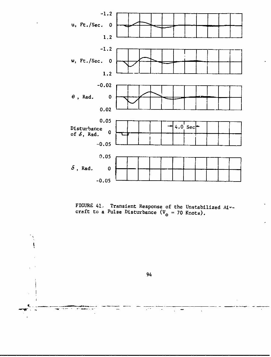
-1.2
U, Ft. /Sec. - -0 jf V1.2
-1.2 --
w, Ft./Sec. 0 -
- i1.2
-0.02
e, R ad . 0 - - ý m m-
0.02
0.05 4Disturbance
- . eof 6, Rad. 0 -
-0.05 i
0.05
, Rad.
0
-0.05
FIGURE 41, Transient Response of the Unstabilized AIv-craft to a Pulse Disturbance (Vo = 70 Knots).
94
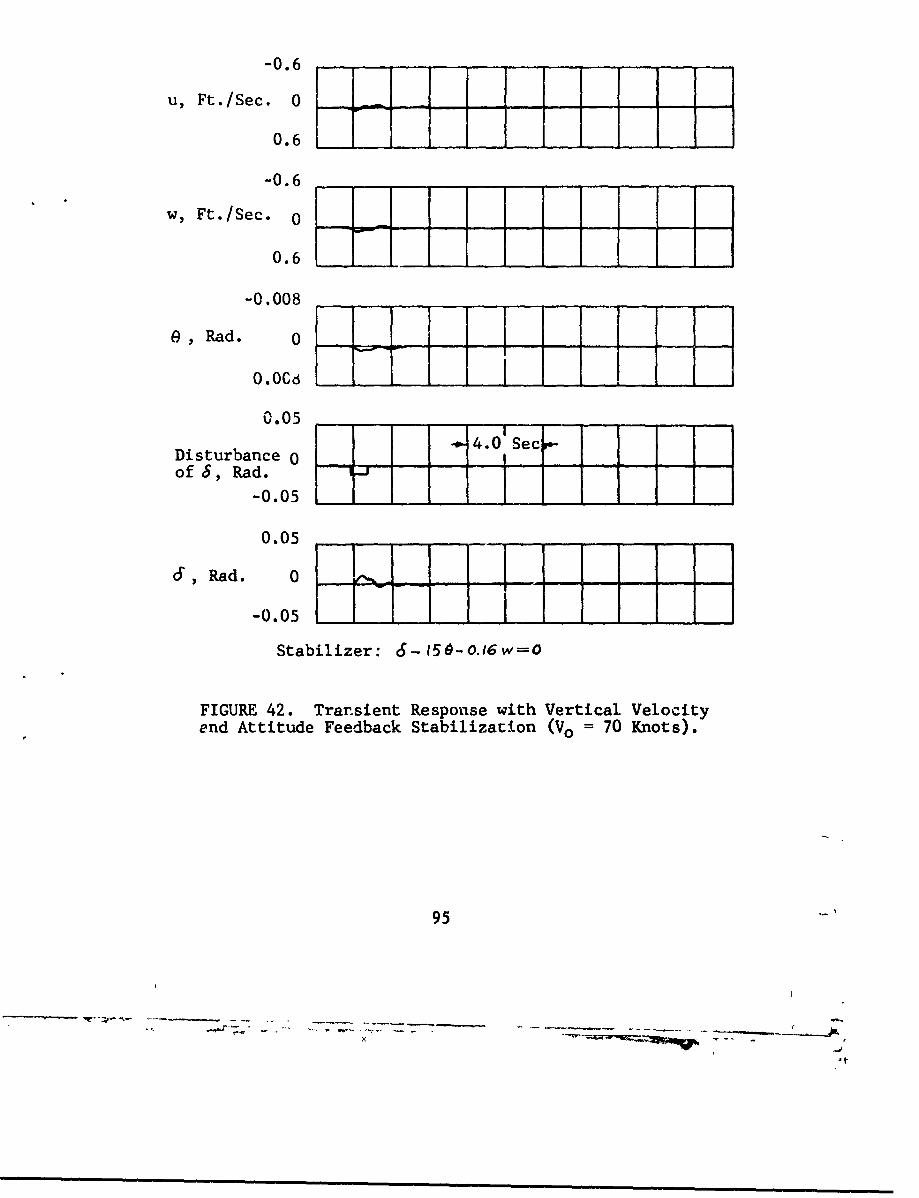
-0.6
u, Ft./Sec. 0 B0.6
-0.6
w, Ft./Sec. 0
0.6 1 1 1 1 11 __-0.008
0, Rad. 0
0.05 Sec-
Disturbance 0 4of 8, Rad. - 1
-0.05
0.056, ad. 0 w _
-0.05 1 1I
Stabilizer: (5-15-0-.16w=O
FIGURE 42. Trar.sient Response with Vertical Velocityend Attitude Feedback Stabilization (Vo = 70 Knots).
95
- - - - - - - - - - - S
i m i • t

MODIFICATION OF SLIPSTREAM TO AUGMENTLIFT AND CONTROL
This section presents the results of an analyticalstudy of the effect of the nonuniformity of the velocity ofa jet o.. the lift coefficient of an immersed wing.
The equation of the lift coefficient for a rectangu-lar wing totally immersed in a circular jet, as presented inReference 3, is
Sa [ i -) (101)
where O = angle of attack, radiansS= radius of the jet, feet
= chord of the wing, feet= ratio of free-stream to Jet velocity
This equation has been derived with the assumption that thevelocity of the jet is uniform throughout any cross sectionperpendicular to the direction of flow. In that case thereexists a single velocity potential in the jet, 4j , whichsatisfies Laplace's equation and is also subject to the jetboundary conditions.
In extending the theory to cover a jet with non-uniform velocity distribution, it is necessary that the velo-city pattern is such that Lne jet flow is still a potentialone. A flow with a number of concentric velocity zones ineach of which the velocity is uniform, such as illustratedin Figure 43, meets this requirement.
In this particular case, the whole jet is consideredto consist of four separate concentric "sub-jets", in eachof which there exists a velocity potential. Each potentialhas to satisfy its own boundary conditions.
96
U -C
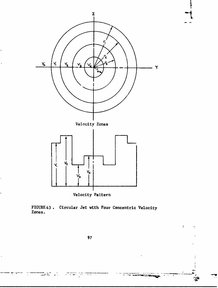
z .e
Velocity Zones
,IT
Velocity Pattern
FIGURE43 . Circular Jet with Four Concentric VelocityZones.
97
- ~- ---- ----- A'
" •d4
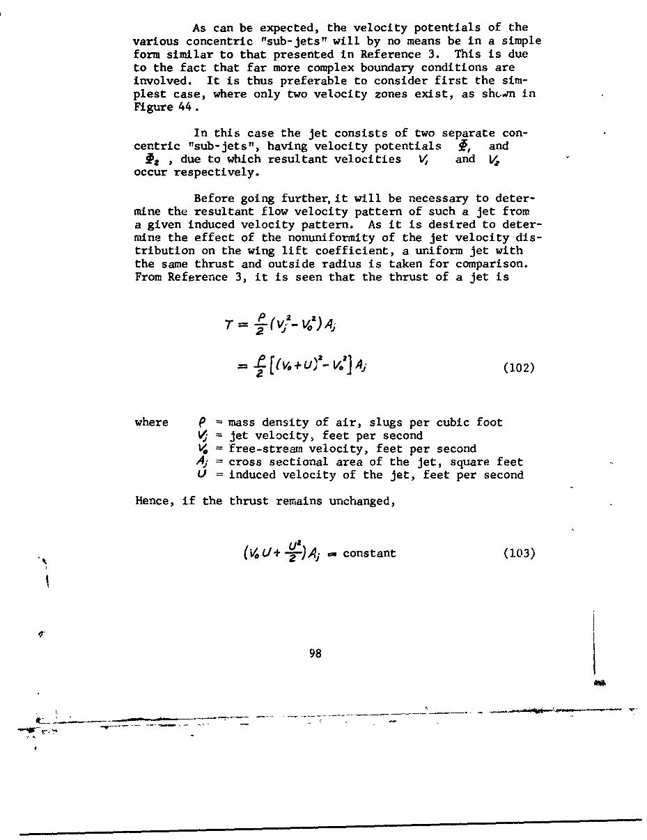
As can be expected, the velocity potentials of thevarious concentric "sub-jets" will by no means be in a simpleform similar to that presented in Reference 3. This is dueto the fact that far more complex boundary conditions areinvolved. It is thus preferable to consider first the sim-plest case, where only two velocity zones exist, as shcwn inFigure 44.
In this case the jet consists of two separate con-centric "sub-jets", having velocity potentials 1, and
13 , due to which resultant velocities V, and V.occur respectively.
Before going further, it will be necessary to deter-mine the resultant flow velocity pattern of such a jet froma given induced velocity pattern. As it is desired to deter-mine the effect of the nonuniformity of the jet velocity dis-tribution on the wing lift coefficient, a uriform jet withthe same thrust and outside radius is taken for comparison.From Reference 3, it is seen that the thrust of a jet is
T= 2-a
21 I.÷fv] A (102)
where P = mass density of air, slugs per cubic footS= jet velocity, feet per secondS= free-strean velocity, feet per secondAy = cross sectional area of the jet, square feetU = induced velocity of the jet, feet per second
Hence, if the thrust remains unchanged,
(VOt]+ 2uýL-) Ai =- constant (103)
98
a
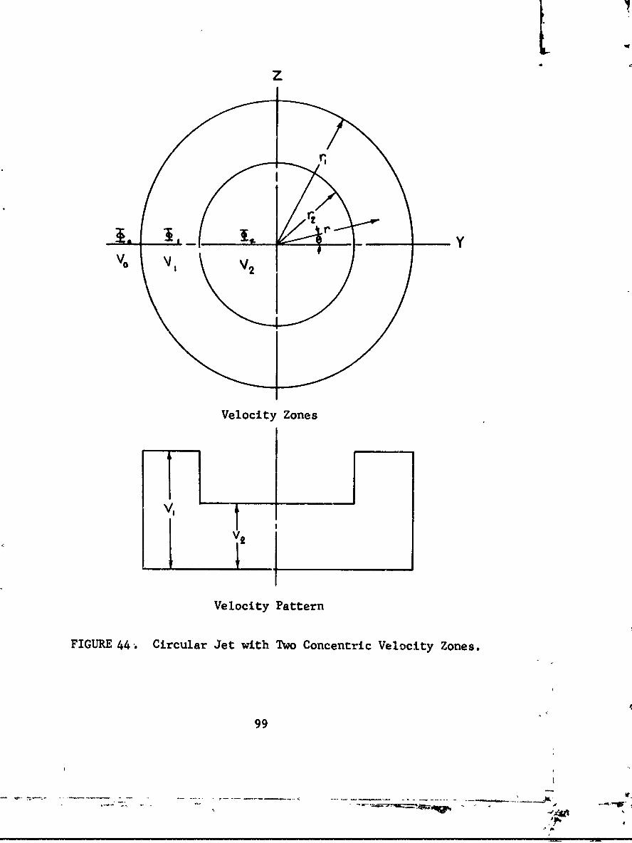
L.Z
,, V 2•
Velocity Zones
v, t
Velocity Pattern
FIGURE 44 . Circular Jet with Two Concentric Velocity Zones.
99
Aw.
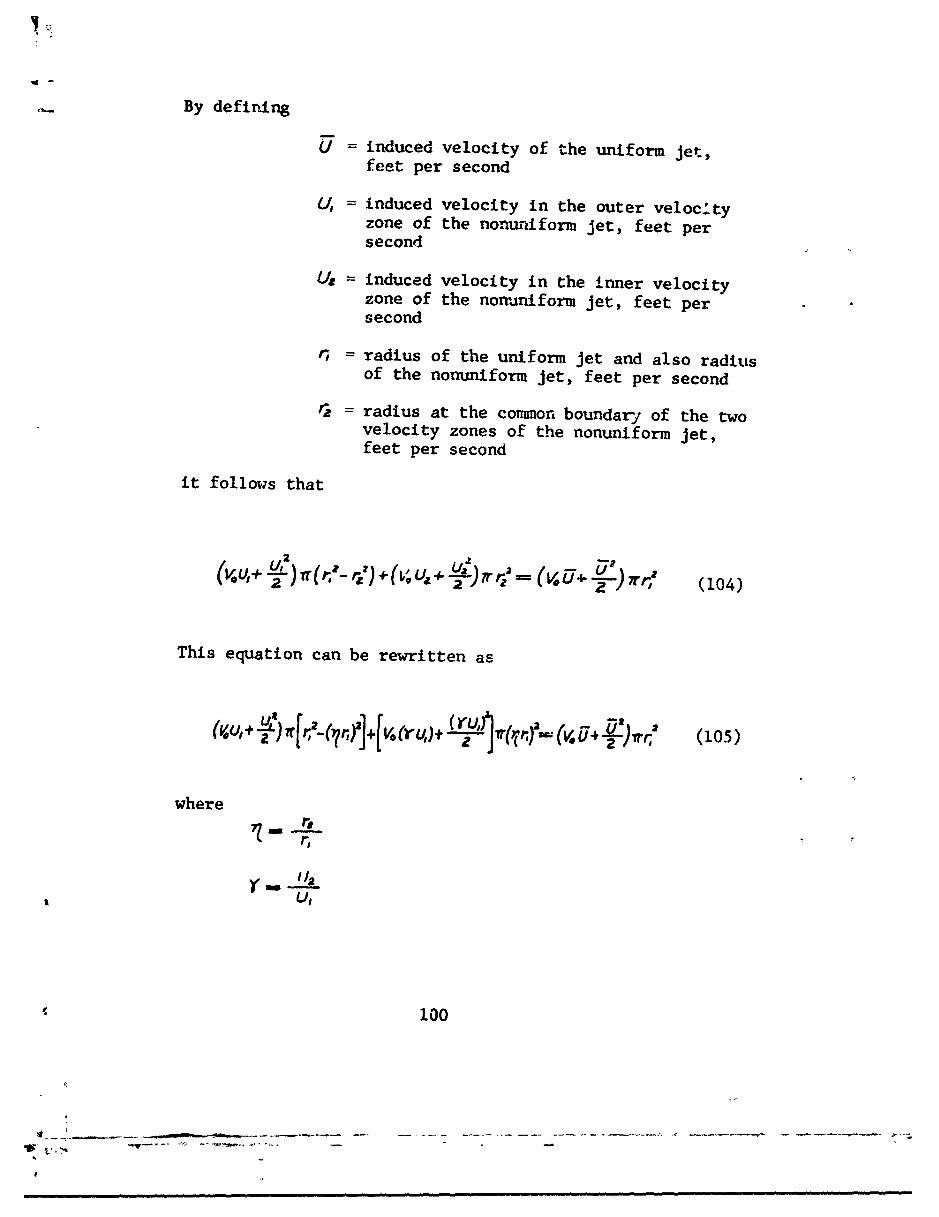
By defining
L = induced velocity of the uniform jet,feet per second
U, = induced velocity in the outer veloc.tyzone of the nonuniform jet, feet persecond
Ue = induced velocity in the inner velocityzone of the nonuniform jet, feet persecond
= radius of the uniform jet and also radiusof the nonuniform jet, feet per second
S= radius at the common boundary of the twovelocity zones of the nonuniform jet,feet per second
it follows that
'a 2-)7rr," (104)
This equation can be rewritten as
= L) [r[,--rf1j+[V. frU)+ I"V 2b G 15
where
r,
100
i ...,____,_..,,,- ,,, , ,, ,, ,,, , ,, ,~ e , ,, , ,, , ,,_ , ,, ,,,, , , ,,_,,, , ,, ,,_ , , , , ,, ,, , , ,,,, , , ,, ,,,,,
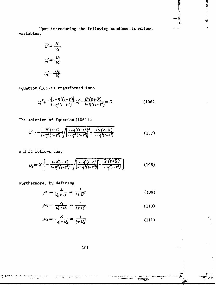
Upon introcucing the following nondimensionalizedvariables,
i. UV.
U, =U,
V.O
Equation (105) is transformed into
[ -'(i_ r-) 'ji_&'(2#_+ ,0 (106)
The solution of Equation (106, is
_, __- ___- r (- -) 1 2 (1'(07)
and it follows that
, -•IY) (108)(-Y1 U•"+'-r, z -,,•j[-,,• r-i~: z8
Furthermore, by defining
/t4 - * -W - (109.)"V, + u I/
VO 1, (110)
V.+U
"V"=IV ÷ /+U1 (Iii)
101

it is possible to evaluate ,u and /4q in terms of A,O? and ) as a result of the use of Equations (107) and
(18), as follows:
/.Il= - - (112)
--- (113)
I- I #
The new boundary conditions for the jet with twovelocity zones are as follows:
L•-• -- ( at Z=O and r,- y<r, (114)
az
3 -Vo(atZ2 0and Oý6Y:Srs (115)
t = at (116)V, ST a r r=r
V, == V=.4 at r=r, (117)
V ft= VI-A&F at r -=r. (0l8)
r~r~ (11)
v , at rmra (119)
102
------- _
w ee --- w -M mw w Awm•• mee •
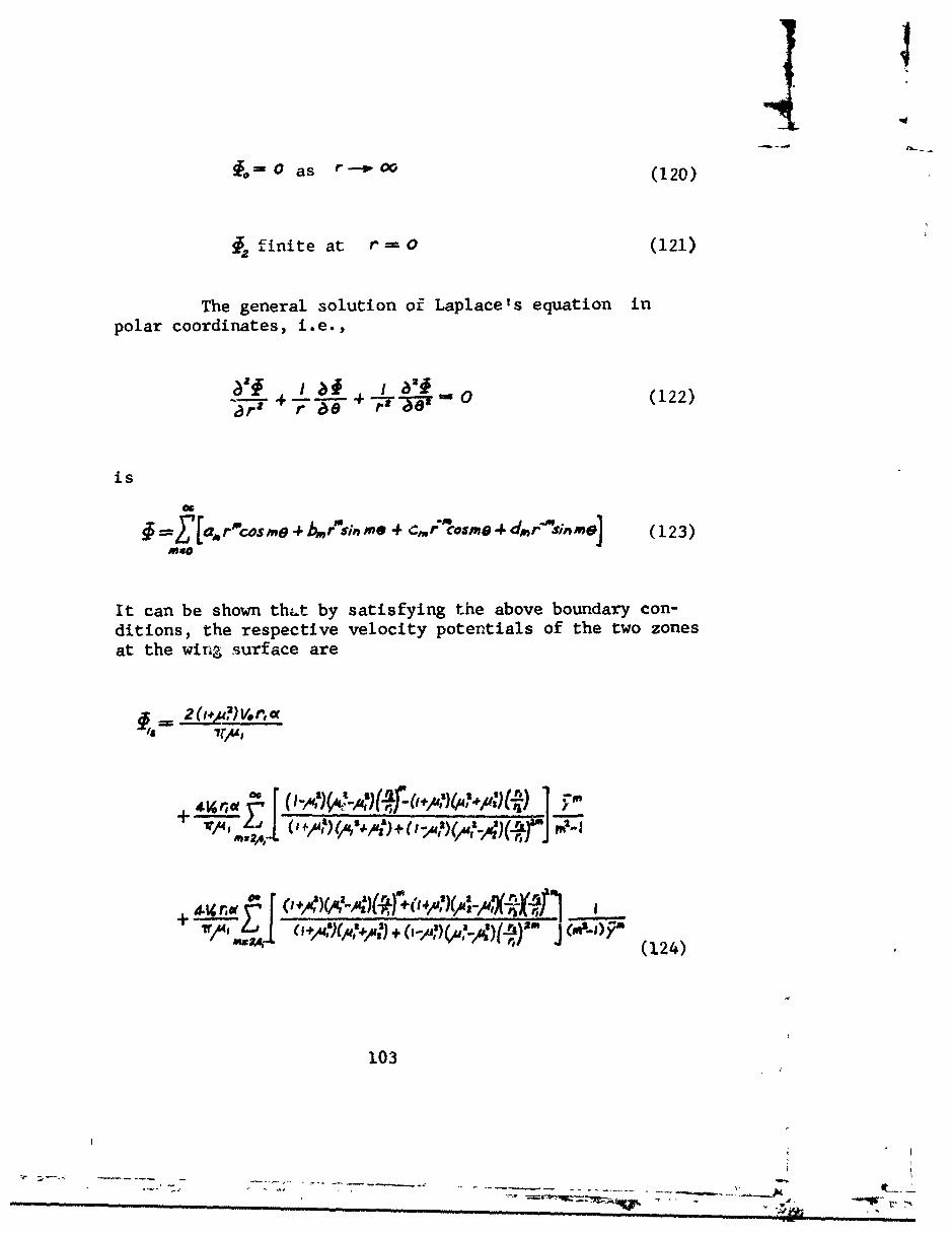
0 as r- oo (120)
finite at r ==AO (121)
The general solution of Laplace's equation inpolar coordinates, i.e.,
alf /10 1a 24(122)
is
~4 [ a.rlco s me +br"'s; n m 4 Sm~o s m a4dm r"'sin m e (123)Mao
It can be shown thLt by satisfying the above boundary con-ditions, the respective velocity potentials of the two zonesat the wing surface are
/S
4AL re( r+0i-A"" ,, 1 +0'4/0)Y')' I
11 (124)
103
-.. .. .- ..w--- -- - - - 4.-
where
Y =-
and
wherd
* ~ ~ILA~ (125)
where
It is seen that the second item in the denominatorof the general expression of the infinite series appearingin Equations (124) and (125), viz. (-,)(,-•t)Cr/,)is in most cases of a higher order and can be neglected.Also, an approximation of Equations (124) and (125) can beachieved by taking m = 2, 4, 6, and 8, and disregardingthe remaining terms of the infinice series which convergefast. There follows:
104
t
,\~
2 V, r, tISI
+ 2. r.
+ a( -)V.ricd(fI. -JN t ~ F},,)
+ z(Wt-e,I)4g) V-0 . NA -
?~#* (~A')(2~#t)Loyi
- Va (127
[a( I 77105
-r A . -1 Y4
The lift coefficient of the totally immersed wing,based on free-stream dynamic pressure, o , is
I V.
c= -fs 5 cfaS (128)
I ra 0
where it, and 1ts are the functions of y given inEquations (126)and (127).
Two sample calculations are now made using thefollowing velocity patterns:
r2r, -
u, 2
U,
U" V V,i.e., &C 0.5
(2) r, = T
U,
V" •i.e.,,, 0 .5
The lift coefficient of the wing has been calculatedfor the two cases as follows:
(1) CL,-9.82c (129)
(2) C1. 10,31 r, (130)
106
Also, by setting
S- = 0.5
In Equation (101), there results that the lift coefficient ofa wing immersed in a uniform jet with the same thrust asthat in each of the two nonuniform jets is
L = /0.•2 -' (131)
It is seen from the above that ajet with an induced velocityirn the outer zone doubie that in the inner zone gives a liftcoefficient about 2 percent less than a uniform jet havingthe same thrust. On the other hand, a jet with an inducedvelocity in the inner zone double that in the outer zonegives a lift coefficient about 3 percent more than a uni-form jet having the same thrust.
The velocity pattern of an actual slipstream isusually very nonuniform. However, this can be well approxi-mated by a jet consisting of a number of concentric "sub-jets", by means of which an analysis similar to thatperformed above for the case of two "sub-jets" can be workedout. Without finding the solution in detail, it can beconcluded qualitatively at this stage that by shifting thepeak velocity at any cross section of the jet toward thecenter, the lift on the wing will increase.
The result of the above analysis is substantiatedby the test data of References 2 and 13. As reported therein,the propeller with a blade angle, AO.75 , of 3.7 degreesgives a higher lift coefficient than the one with a bladeangle of 8.0 degrees. As can be seen from the dynamicpressure survey diagram (see Figure 45, reproduced fromReference 2), for 3o.7 = 3.7 degrees the velocity patternis such that the peak is closer to the slipstream center.
107
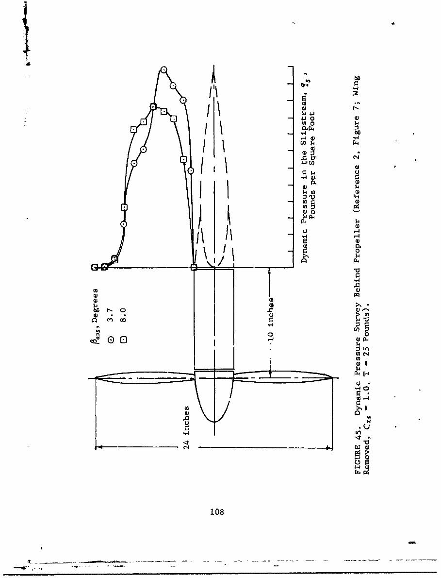
41 00
V) 0-
*14
04 a
S W)
14-a) 02
r-4r) A
~~ C4O
"4.6
C144
02
1082

It should also be noted that an increase of liftcorresponds to an increase of pitching moment about theaircraft center of gravity. Hence, increased wing pirformanme,at constant propeller thrust, can be utilized to increase thecontrollability of the aircraft.
109
THE EFFECT CO WING GEOMETRY ON LIFT
TRAILING EDGE FLAPS
This section presents the result of an investigationof the effect of large flap deflections on the lift coeffi-cient of a wing immersed in a propeller slipstream.
The effective angle of attack, o$ , of the portionof the wing immersed in the propeller slipstream, as indi-cated in Reference 3, is
S= , + • _ - 14.0(132)
The above equation indicates that a change in flapdeflection angle is equal to an equal change of angle ofattack of the wing. This relationship gives quite satis-factory results when compared with test data for small flapdeflection angles, i.e., less than 15 to 20 dcgrees. How-ever, for larger deflection angles the use of Equation (132)often results in values of lift which exceed the experimen-tal values.
This region of higher flap deflections is ofparticular interest for V/STOL aircraft which utilize flapdeflections up to 60 degrees. No theoretical analysis hasbeen found to determine the wing lift for very high flapdeflections, and hence the determination of the lift mustbe accomplished by use of experimental data.
Existing experimental data for the special case ofzero forward speed, /" = 0, have been used here to formu-late empirical correction factors to the basic theory ofReference 3. Under this condition, the increment liftcoefficient accounts for the entire wing lift and can bewr~itten as follows:
AC= c(ii0 (1.33)
110
Iw
where K is an empirically derived correction factor.
"The experimental data utilized for this purpose areobtained from References 2, 4, 12, and 13 for plain, single-slotted, and gowler flaps. The data are compared in Figures46 through 49 with values calculated using Equation (130)with different values of K . It is noted that the testdata can be approximately reproduced by use of a correctionfactor K= cos/,4. In particular, by comparing the test datawith the curves plotted on Figures 46 and 47, it is notedthat for cf/A = 0.3, /(/ ranges between 0.75 and 0.85,whereas for c1/c = 0.6, ,K, = 0.75 provides reasonablyaccurate results. Similarly for the single-slotted flaps,the data on Figure 48 indicate values of /(, of 0.7 and0.6 for ct/c of 0.3 and 0.6, respectively. Also, Figure49 indicates that for Fowler flaps with Cf/c = 0.4, avalue of K, = 0.875 is appropriate.
WING TWIST
The theory presented in Reference 3 for the liftincrement of a wing immersed in a slipstream was developedfor a rectangular, untwisted wing. To a first-order approxi-mation, twist can be introduced into the equations as a localchange of angle of attack. There follows that for a lineartwist distribution, the lift coefficient increment due tothe slipstream can be written as
(/,&) rs1+Y dF(134)/1 I-)'rl I
where Es is the wing twist between slipstream center andperiphery. Since it can be shown that
- -
-'F--- -- (13s) -

0.7
0 0.3 / -.Theory(K, 0.o)
- 0.6 - -• 'Cos(o.7S
0.6 --i- coS (o.,0,)
• co~s(o,.8os,•K- COS(O-i0sf',
0.5 ____,•-i.
0.4
0.11
0.3
0.1
o.240 60 80 1
&f Degrees
FIGURE 46. Variation of Lift Coefficient Increment with FlapDeflection Angle (Test Data from Reference 12, Figure 9a;Plain Flap, CTIS 1.0).
112
if -
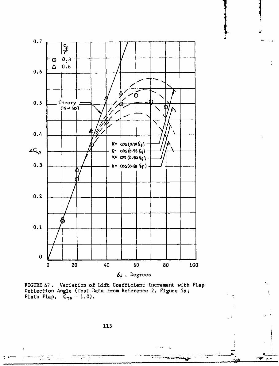
0.7 " ....
-0 0.3-
0.6 0.6
0. 5 Theory
0.4
/K C"OS (0.10
CLS- Ko- , = (0.15 g40 .3 -
- - ( .g f ) -
0.2 -
0.1
0
0 20 40 60 80 1006f , Degrees
FIGURE 47, Variation of Lift Coefficient Increment with FlapDeflection Angle (Test Data from Reference 2, Figure 5a;Plain Flap, C.s = 1.0).
113
r r- - ~ . - ' -v- i
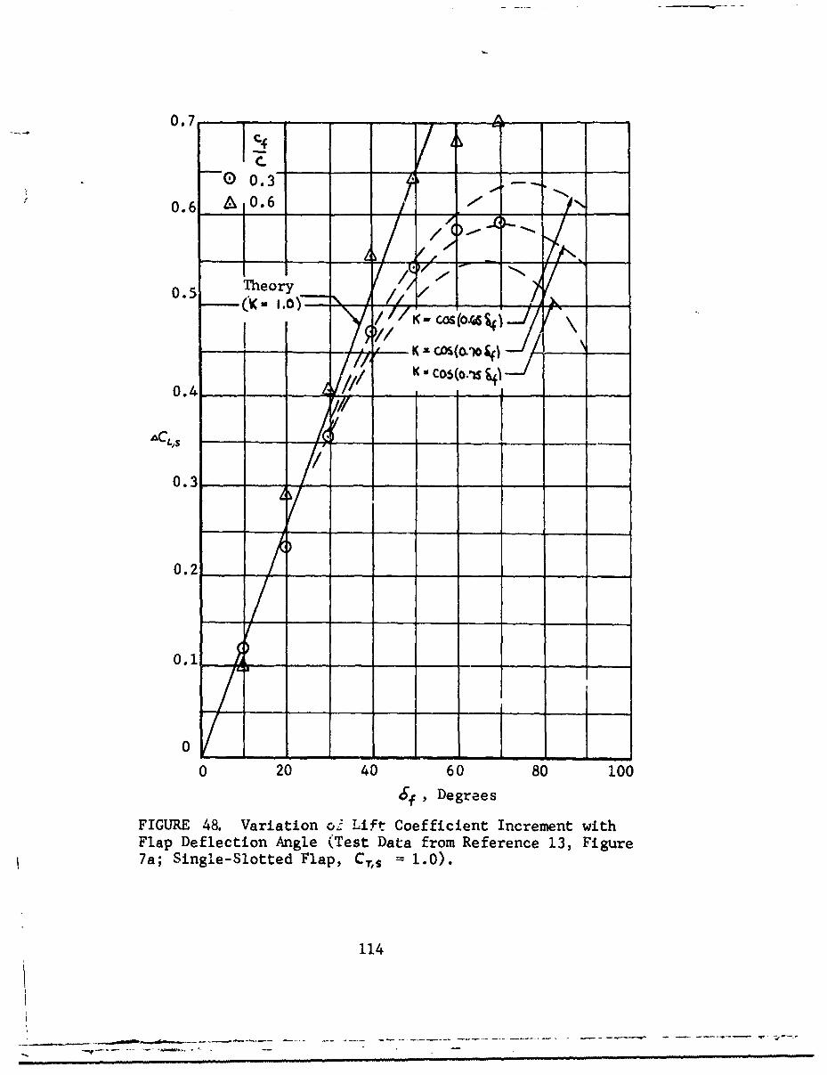
0.7-
0. 6 1?0. 6
0.5 Theory /~
LK xCOS(Olo i
kuC05(o.-.SA
0.3 /
0.2-
0.1-
20 1VI0 040 60 80 100
6,Degrees
FIGURE 48. Variation c3Lift Coefficient Increment withFlap Deflection Angle (Test Data from Reference 13, Figure7a; Single-Slotted Flap, Cr,. = 1.0).
114

I
0.6
0.5 -
Theory
0.4 . -- (• h." - -
ACI -- i
0.3 - -
- - ~K- COS (O.SSSr)-
0.2 Ku nco~~6
/ii I
0 20 40 60 80 100
Sf ,Degrees
FIGURE 49. Variation ci Lift Coefficient Increment with FlapDeflection Angle (Test Data from Reference 4, Fowler TypeFlap, cf/c 0.4, Cý.s = 1.0).
115
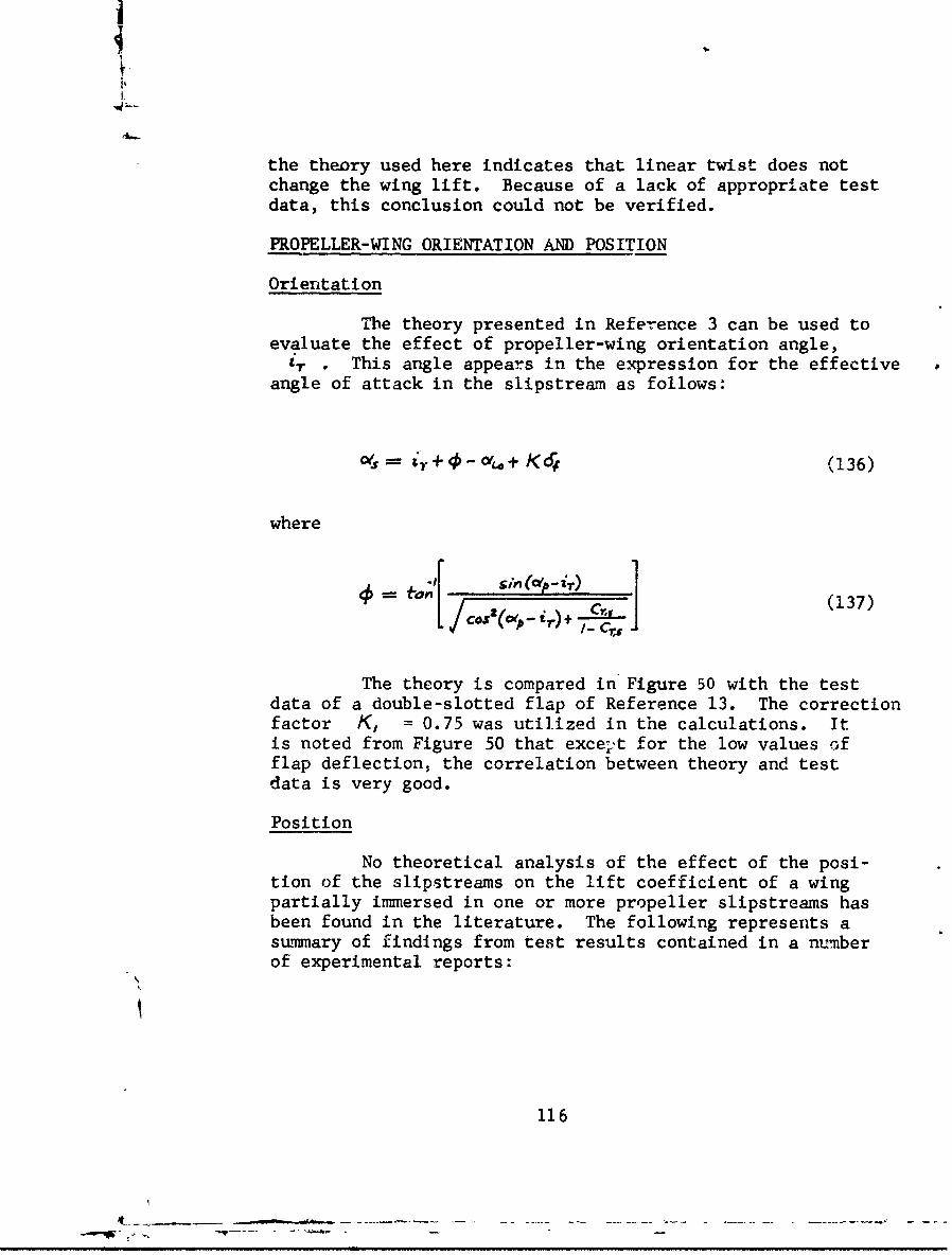
i
the theory used here indicates that linear twist does notchange the wing lift. Because of a lack of appropriate testdata, this conclusion could not be verified.
PROPELLER-WING ORIENTATION AND POSITION
Orientation
The theory presented in Reference 3 can be used toevaluate the effect of propeller-wing orientation angle,
i,. . This angle appears in the expression for the effectiveangle of attack in the slipstream as follows:
s,= &y+ - o+ Kd (136)
where
(o[ T) ] (137)
The theory is compared in Figure 50 with the testdata of a double-slotted flap of Reference 13. The correctionfactor K, = 0.75 was utilized in the calculations. Itis noted from Figure 50 that excep.t for the low values offlap deflection, the correlation between theory and testdata is very good.
Position
No theoretical analysis of the effect of the posi-tion of the slipstreams on the lift coefficient of a wingpartially immersed in one or more propeller slipstreams hasbeen found in the literature. The following represents asummary of findings from test results contained in a numberof experimental reports:
116

TEST DATA
o T, Degrees
E) 5
0.8
0.6
CL's
0.4
>/0.2
0 20 40 60 80 100
Flap Deflection Angle, 6j , Degrees
FIGURE 50. Effect of Wing Incidence on Lift Coefficient(Test Data from Reference 13, Figure 9a; Double-Slotted Flap,
C-,s = 1.0).
117
-r.....-.-...
Longitudinal
References 2, 9, and 11 show some data on the effectof the longitudinal position. These data, which are notentirely consistent, indicate that the optimum wing-propellerrelative position is such that the wing leading edge is about0.3 to 0.5 propeller diameter behind the propeller disc plane.
Vertical
The test data presented in References 2, 9, and 11indicaze that maximum lift is obtained when the verticalposition of the wing is close to the propeller center.
118
"4 -' .|.
B IBLIOGRAPHY
1. Anderson, R. F., Determination of the Characteris-tics of Tapered Wings, NACA TR 572, 1936.
2. Draper, J.W., and Kuhn, R.E., Some Effects of Pro-peller Operation and Location on Ability of a Wingwith Plain Flaps to Deflect Propeller SlipstreamDownward for Vertical Take-Off, NACA TN 3360, J955.
3. Dynasciences Corporation, Effects of Propeller Slip-2tream on V/STOL Aircraft Performance and Stability,TRECOM Technical Report 64-47, U.S. Army AviationMateriel Laboratories,* Fort Eustis, Virginia,August 1964.
4. Fink, M.P., Mitchell, R.G., and White, L.C., Aero-dynamic Data on a Large Semispan Tilting Wing with0.6-Diameter Chord, Fowler Flap, and Single Pro-peller Rotatir,6 UP at Tip, NASA TN D-2180, 1964.
5. Fink, M.P., Mitchell, R.G., and White, L.C., Aero-dynamic Data on Large Semispan Tilting Wing with0.6-Diameter Chord, Single-Slotted Flap, and SinglePropeller Rotating Down at Tip, NASA TN D-2412,1964.
6. Gessow, A., and Myers, G.C., Aerodynamics of theHelicopter, The MacMillan Co., New York, New York,1952.
7. Hamilton Standard Division, United Aircraft Corpora-tion, Generalized Performance of Conventional Pro-pellers for VTOL-STOL Aircraft, Report No. HS-1829,Hamilton Standard Division, United Aircraft Corpora-tion, Windsor Locks, Connecticut, March 1958.
8. Harper, C.W., and Maki. R.L., A Review of the StallChaiacteristics of Swept Wings, NASA TN D-2373,July 1964.
*Formerly U.S. Army Transportation Research Command
119
-.. .. . - ------- -- - ....... ---------. - .--- '- ----•-e -- - -
9. Hayes, W.C., Kuhn, R.E., and Sherman, I.R., Effectsof Propeller Position and Develop on the SlipstreamDeflection Characteristics of a Wing-Propeller Con-figuration Equipped with a Sliding and Fowler Flap,NACA TN 4404, 1958.
10. Jacobs, E.N., and Sherman A., Airfoil SectionCharacteristics as Affected by Variations in ReynoldsNumber, NACA TR 586, 1939.
11. Kuhn, R.E., Investigation of the Effects of GroundProximity and Propeller Position on the Effective-ness of a Wing with Large-Chord Slotted Flaps inRedirecting Propeller Slipsti .ams Downward forVertical Take-Off, NACA TN 3629, 1956.
12. Kuhn, R.E., and Draper, J.W., An Investigation ofa Wing Propeller Configuration Employing Large ChordPlain Flaps and Large-Diameter Propellers for Low-Speed Flight and Vertical Take-Off, NACA TN 3307,1954.
13. Kuhn, R.E., and Draper, J.W., Investigation ofEffectiveness of Large-Chord Slotted Flaps inDelecting Propeller Slipstreams Downward forVertical Take-Off and Low Speed Flight, NACA TN3364, 1955.
14. Kuhn, R.E., and Draper, J.W., Investigation ofthe Aerodynamic Characteristics of a Model Wing-Propeller Combination and of the Wing and PropellerSeparately at Angles of Attack up to 900, NACA TR1263, 1956.
15. Kuhn, R.E., and Hayes, W.C., Jr., Wind-TunnelInvestigation of Longitudinal Aerodynamic Charac-teristics of Three Propeller-Driven VTOL Config-urations in the Transition Speed Range, IncludingEffects of Ground Proximity, NASA TN D-55, 1960.
120
--t_
16. Mort, K.W., and Yaggy, P.F., Aerodynamic Charac-teristics of a Full-Scale Propeller Tested withBoth Rigid and Flapping Blades and with CyclicPitch Control, NASA TN D-1774, May 1963.
17. Newson, W., and Kirby, H., Flight Investigation ofStability and Control Characteristics of a 1/9 ScaleMooel of a Four-Propeller Tilt-Wing V/STOL Trans-port, NASA TN D-2443, September 1964.
18. Newson, W.A., Jr., and Tosti, L.P., Slipstream FlowAround Several Tilt-Wing VTOL Aircraft Models Opera-ting Near the Ground, NASA TN D-1382, September 1962.
19. Olcott, J.W., Tests of a Hamilton Standard Fourway,21-Inch-Diameter Model Propeller Employing The U.S.Navy Airborne Model Test Facility, Report No. 675,Princeton University, Princeton, New Jersey, April1964.
20. Payne, H.E., III, and Cromwell, C.H., III, A Sta-bility Analysis of Tilt-Wing Aircraft (Experimental)Report No. 478, Princeton University, Princeton,New Jersey, May 1960.
21. Pegg, R.J., Summary of Flight-Test Results of theVZ-2 Tilt-Wing Aircraft, NASA TN D-989, February1962.
22. Reeder, J.P., Handling Qualities Experience withSeveral VTOL Research Aircraft, NASA TN D-735, 1961.
23. Ribner, H.S., Formulas for Propeller in Yaw andCharts of the Side Force Derivative, NACA TR 819,1945.
24. Schrenk, 0., A Simple Approximation Method forObtaining Spanwise Lift Distribution, NACA TM 948,1940.
121
25. Sleeman, W.C., and Linsley, E.L., Low Speed Wind-Tunnel Investigation of the Effects of PropellerOperation at High Thrust on the Longitudinal Sta-bility and Trim of a Twin-Engine Airplane Con-figuration, NACA RM L52D04, 1952.
26. Stueper, J., Effect of Propeller Slipstream onWing and Tail, NACA TM 874, 1938.
27. Taylor, R.T., Wind-Tunnel Investigation of Effectof Ratio of Wing Chord to Propeller Diameter withAddition of Slats on the Aerodynamic Characteris-tics of Tilting-Wing VTOL Configurations in theTransition Speed Range, NASA TN D-17, 1959.
28. Ward, J.F., Structural Loads Surveys on Two Tilt-Wing VTOL Configuration, NASA TN D-729, 1961.
29. Yaggy, P.F., and Mort, K.W., Wind-Tunnel Tests ofTwo VTOL Propellers in Descent, NASA TN D-1766,March 1963.
30. Yaggy, P.F., and Rogallo, V.L., A Wind-TunnelInvestigation of Three Propellers Through anAngle-of-Attack Range from 0Q to 850, NASA TN D-318,May 1960.
31. Josephs, L.C., VTOL, Vought, Hiller, Ryan, VHR-447Tri-Service Transport, Vol. 4, Stability and Con-trol Report, Part 1, Stability and Control, ReportNo. AER-ElR-13342, Chance Vought Corporation,April 1961.
32. Cromwell, C.H., III, and Payne, H.E., A Stability-Analysis of Tilt-Wing Aircraft, Report No. 477,Princeton University, Princeton, New Jersey, May1960.
122
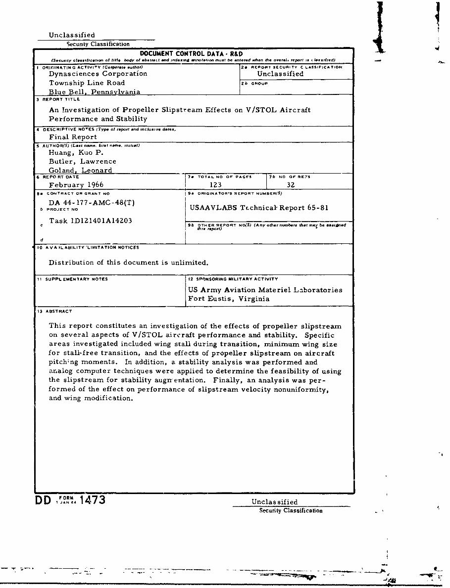
Unclas sifiedSecunty Classification DA
DOCUMENT CO)NTROL DATA- R&D
(Securty classif•cation of title body Of abstract and indexing annotarton must be entered when the oversl report is c lassihed)
I ORIGINATING ACTIVITY (Corporate author) 2& ARCPORT SECURITY C LASSIFICATION
Dynasciences Corporationj Unclassified
Township Line Road 2b GROUP
Blue Bell, Pennsylvania3 REPORT TITLE
An Investigation of Propeller Slipstream Effects on V/STOL AircraftPerformance and Stability
4 DESCRIPTIVE NOTES (Type of report and inclusive dates,
Final Report5 AUTHOR(S) (Last name. first name, initial)
Huang, Kuo P.Butler, LawrenceGoland, Leonard
6 REPORT DATE 70 TOTAL NO OF PAGFS 7b NO OF RE-S
February 1966 123 328a CONTRACT OR GRANT NO g9 ORIGINATOR'S REPORT NUMBER(S)
DA 44- 177-AMC-48(T) Lb PROJECT NO USAAVLABS Technical" Report 65-81
Task ID121401A14203c 9b OTHER REPORT No(S) (Any other numbers that may be easioned
thi# report)
dj
10 AVA IL ABILITY 'LIMITATION NOTICES
Distribution of this document is unlimited.
11 SUPPLEMENTARY NOTES 12 SPONSORING MILITARY ACTIVITY
US Army Aviation Materiel LaboratoriesFort Eustis, Virginia
13 ABSTRACT
This report constitutes an investigation of the effects of propeller slipstream
on several aspects of V/STOL aircraft performance and stability. Specificareas investigated included wing stall during transition, minimum wing sizefor stall-free transition, and the effects of propeller slipstream on aircraftpitch;ng moments. In addition, a stability analysis was performed andanalog computer techniques were applied to determine the feasibility of usingthe slipstream for stability augrrentation. Finally, an analysis was per-
formed of the effect on performance of slipstream velocity nonuniformity,and wing modification.
FORM
DD I 1473 UnclassifiedSecurity Classification
S. .. ..... . ... ........ .... . .. ........ .. . .,v ,., . - .em. .. . ..... . ..... ...... ...
Unclas sifiedSecurity Classificution
14. KEY WORDS LINK A LINK 0 LINK C
--- ROLE WT RQLE WT ROLE WT
Slipstream: effects of propeller on V/STOLaircraft stability and per-formance
V/STOL Aircraft: effect of propeller slip-
stream on stability andperformance
INST RMUCTIONS
I. ORIGINATING ACTIVITY: Enter the name and address 10. AVAILABILITY/LIMITATION NOTICES: Enter any lim-of the contractor. subcontractor, grantee, Department of De- itations on further dissemination of the report, other than thosetense activity or other organization (corporate author) issuing imposed by security classification, using standard statementsthe rep -,..t. I such as:2&. REPORT SECURITY CLASSIFICATION: Enter the over' (1) "Qualified requesters may obtain copies of thisall security classification of the report. Indicate whether".Restricted D)ata" is included. Ma-cing is to be in accod- report from DDC"anc- with appropriate security regulations. (2) "Foreign announcement and dissemination of this2b. GROUP: Automatic downgrading is specified in DOD Di- report by DDC is not authorized."rective 5200. 10 and Armed Forces Industrial Manual. Enter (3) "U. S. Government agencies may obtain copies ofthe group numher. Also, when applicable, show that optional this report directly from DDC. Other qualified DDCmarkings have been used for Group 3 and Group 4 as author- users shall request throughized.
3. REPORT TITLE. Enta. the complete report title in all (4) "U. S. military agencies may- obtain copies of thiscapital letters. Titles in all cases should be unclassified.It a meaningful title cannot be selected without classifica- rhplr rect froua stion. show title classification in all capitals in parenthesisimmediately following the title. ,_."
4. DESCRIPTIVE NOTES: If appropriate, enter the type of (5) "All distribution of this report is controlled. Qual-report, e.g., interim, progress, summary, annual, or final. ified DDC users shall request throughGive the inclusive dateb when a specific reporting period iscovered.
If the report has been furnished to the Office of Techr' 'al5. AUTHtOR(S)y Enter the name(s) of author~s) as shown on S•ervices, Department of Commerce, for sale to the public, 'ndi-or in the report. Enter last name, first name, middle initial. crte Department o merce, f seo t u nIf military, show rank and branch of service. The name of cate this fact and enter the price, if known.the principal author is an absolute minimum requirement. 11. SUPPLEMENTARY NOTES: Use for additional explana-6. REPORT DATE. Enter the date of the report as day, t2r NOtes.month, year. or month, year. If more than one date appears 12. SPONSORING MILITARY ACTIVITY: Enter the name ofon the report, use date of publication. the departmental project office or laboratory spo. ioring (pay-
ing for) the research and development. Include address.7a. TOTAL NUMBER OF PAGES. The total page countehou!d follow normal pagination procedures, Le., enter the 13 AIHSTRACT: Enter an abs. . giving a brief and factualnumber of pager containing information, -.summary of the document indicative of the repnrt, even though
it may also appear elsewhere in the body of the technical re-7b. NUMBER OF REFERENCES: Enter the total number of p,,rt. If adcýitional space is required, a continuation sheetreferences cited in the report. shall be attached.
8a. CONTRACT OR GRANT NUMBER: If appropriate, enter It is highly desiratle that the abstract of classified re-the applicable number of the contract or grant under which ports be unclassified. `;ach parapraph of the abstract shallthe r-port was written. end with an indication t f the military security classification8b. 8c, & 8d. PROJECT NUMBER: Enter the appropriate of the infomration in the paragraph, represented as (TS), (S),military department identification, such as project number, (C). or ().subproject number, system numbers, task number, etc. There is n. limitation on the length of the abstract. How-9a. ORIGINATOR'S REPORT NUMBER(S): Enter the offi- ever, the suggested length is from ISO to 225 words.cial report number by which the document will be identified 14. KEY WORDS: Key words are technically meaningful terms" " and controlled by the originating activity. This number must or short phrases that characterize a report and may be used vsbe unique to this report. index entries for cataloging the repoer. Key words must be9b. OTHER REPORT NUMBER(S): If the report has been selected so that no security classification is required. Iden-assigned any other report numbers (either by the originator .ir-, such as equipment model designation, trade name, mill-or by the sponsor), also enter this number(s). tary project code iname, geographic location. may bef used as
key words but will be followed by an indication of technical
:-ontext. The assignment of links, rules, and weight.i isoptional.
Unclas sie__edj- rtCl a ssitf Icat i-o-n700466