ad-aii52 vax using berkeley unix and ethernet · pdf filethe bulk data system . . . . .. ......
TRANSCRIPT

AD-Aii52 953 INTERFACING THE VAX 11/780 USING BERKELEY UNIX 42BSD 1/2,AND ETHERNET BASED X..(U) AIR FORCE INST OF TECHWRIGHT-PHTTER5ON AFB OH SCHOOL OF ENGI. E BERNARD
7 NLSIIDDEC 84 AFIT/GCS/ENG/84D-4-VOL-i F/G 9/2 N

L1. g2
11111.25 ~IIL4 111 1.
II1111111
MICROCOPY RESOLUTION TEST CHART
NATIONAL BUREAU OF STANDARDS- 1963-A

REPRODUCED AT GOVERNST EXPENSE ")
INIn
I-F
INTERFACING THE VAX 11/780 USINGBERKELEY UNIX 4.2BSD AND
ETHERNET BASED XEROX NETWORK SYSTEMS
THESIS(Volume 1 of 3)
Craig E. BernardCaptain, USAF
Cl AFIT/GCS/ENG/84D-4
DTICELECTE
S DEPARTMENT OF THE AIR FORCE
AIR UNIVERSITY
AIR FORCE INSTITUTE OF TECHNO
Wright-Patterson Air Force Base, Ohio
...... ..... . . . - . ..- -. . -

INTERFACING THE VAX 11/780 USINGBERKELEY UNIX 4.2BSD AND
ETHERNET BASED XEROX NETWORK SYSTEMS
THESIS(Volume 1 of 3)
Craig E. BernardCaptain, USAF
AFIT/GCS/ENG/84D-4 D TIC
ELECTEAFR 2 61985
v fE
Approved for public release; distribution unlimaited
- -4 - - - . . . .

AFIT/GCS/ENG/84D-4
Acce.s l on For
7IC T:.
Ju! t
INTERFACING THE VAX 11/780 .....By~
USING BERKELEY UNIX 4.2BSD fIztr,
AND ETHERNET BASED XEROX NETWORK SYSTEMS A,,I
THESIS
(Volume 1 of 3)
Presented to the Faculty of the School of Engineering
of the Air Force Institue of Technology
Air University
In Partial Fulfillment of the
Requirements for the Degree of
Master of Science in Information Systems
Craig E. Bernard, B. S.
Captain, USAF D TICV-".'h' "CTE
Art 2 3 G85
December 1984
E
Approved for public release; distribution unlimited
-7...

~rinr my..- ~Prefacet
The purpose of this study was to assist the Program and
* Financial Control (P&FC) office in the interfacing of the
VAX 11/780, using the Berkeley Unix 4.2BSD operating system,
with Xerox office automation systems on an Ethernet local
area network. The interfacing desired by P&FC would allow
electronic filing, mailing, and printing services between
the VAX 11/780 and Xerox office automation systems on an
* Ethernet.
I would like to thank my thesis advisor, Dr. Gary
Lamont, for his support and guidance in this research,
especially during the rough spots encountered in this
- investigation. I would also like to thank my thesis reader,
Major Walt Seward,, for his valued comments on this thesis
effort.
I would like to especially thank Mr. Clarence Hoop, Mr.
- George Grenley, and Lt. Jim Child for their assistance in
* this research. These individuals were very helpful in the
acquiring of current information for this investigation.
Finally, I would especially like to thank my wife,
*Linda, for proofreading the drafts for this thesis, and for
giving me encouragement during this investigation.
Craig E. Bernard L

3
ai
Table 2L Content&
Volume 1
Page
Preface o . . . * *. ii
List of Figures . . . . . . . . . . . .vii
List of Tables . . . . ...... * . ix
I. Introduction .... ... ....... I-x
Kii Ethernet Background e o, 1-3Design Goals . . . . . .e. . 1-4Topology . . . . . . . o e 1-5Physical Components . . 1-7Structure . . . . . . . 1-9
Thesis Investigation Overview o I-1Background . . . . . . . . . . . . . . I-11Problem . . . . . . . . . . . . . . . 1-11
Approach ••. . .. 1-13Materials and Equipment . . 1-14
Outline of Thesis . . . . . . . . . . . . 1-15
II. Protocol Requirements . . . . . . . . . . . . II-1
Introduction . . . . . . . @ @ * * e * * * II-1The ISO Model . . . . . . . . . . . . . . II-1
Physical Layer Protocol . . . . . . . . 11-3Data Link Layer Protocol o . . o . 11-3Network Layer Protocol . . . . o . . . 11-4Transport Layer Protocol . . . . . . . 11-5Session Layer Protocol . . . . . . . . 11-7Presentation Layer Protocol . . . . . . 11-8Application Layer Protocol . . . . . . 11-9
Xerox Network Structure , ........ 11-9Overview 11-9XNS Physical Ly;r. ..- 10XNS Data Link Layer. . ...... . 11-13XNS Network Layer .... • ..... 11-18
Local Networking asApplied to the Ethernet . . . . . . 11-18Internetworking as Appliedto Xerox Network Systems . . . . . . 11-18
iii

Page
XNS Transport Layer . . . . . . . . . . 11-21XNS Routing Information Protocol . . 11-22XNS Error Protocol . . . . * . . . . 11-25XNS Echo Protocol . . . . . . . . . 11-28XNS Sequenced Packet Protocol . . . 11-30XNS Packet Exchange Protocol .... 11-33
XNS Session Layer . . . . . . . . . . . 11-33XNS Presentation Layer 0 . .. . . . . 11-36XNS Application Layer . . . . . . . . . 11-37TCP/IP Requirements 11-38
Summary 11-39
III. Protocols Implementation Status . . . . . . . III-1
Introduction . . . . . . . . * * III-1Berkeley Unix 4.2BSD Operating System . . 111-3
User Interface . . . . . . . . . . . . 111-4Internal Structure . . . . . . . . . . 111-5
Socket Layer . . . . . . . . . . . . 111-5The Communication Protocol Layer . . 111-6The Hardware Interface Layer . . . . 111-6
DARPA Protocols Support . . . . . . . . 111-7Ethernet and XNS Software Support . . . 111-8
Overview of Implemented Protocols . . . . 111-9XNS Level Zero . . . . . . . . .... 111-9XNS Levels' One and Two . . . . .II-11XNS Level Three . . . . . . . . . . . . 111-14XNS Level Four . . . ......... 111-15TCP/IP Requirement . . . . . . . . . . 111-18
Summary 111-18
IV. General Design of a XNS Protocol . . . . . . IV-i
Introduction. . . . IV-lThe Courier Protocol . . . . . . . . . . . IV-2Xerox Bulk Data Transfer Protocol . . . . IV-8General Design of theXerox Bulk Data Transfer Protocol . . . . IV-11
The Initiator. ........ .... IV-13Null Transfer . . . . . . . . . . . IV-19Immediate Transfer . . . IV-19Third-Party Transfer . . . . . . . . IV-20
The Produce Remote Procedure . .. .. IV-20Null Transfer . . . . . . . . . . . IV-22Immediate Transfer . . . . . . . . . IV-22Third-Party Transfer. . ..... IV-22
The Consume Remote Procedure . . . . . IV-23Null Transfer . . . . . . . IV-23Immediate Transfer . .. . .. ... IV-25Third-Party Transfer . . . ..... IV-25
Summary . . . . . . . . . a IV-26
iv
Page
V. Implementing and Testing of the LXerox Bulk Data Transfer Protocol . . . . . . V-i
Introduction o . ............ V-IImplementation . . . . . . . . . . . . V-3
Detailed Design Implementation . . . . V-3The Initiator System . . . . . . . .. V-4The Produce andThe Consume Systems . . . . . ... V-7The Bulk Data System . . . . . . V-15
The Send Remote Procedure . . . . V-21The Receive Remote Procedure o . V-22The Cancel Remote Procedure . . . V-23
Code Implementation . . . . . . . . . . V-24Testing . . . . . . . . . . . . . . . . . V-26
Static Analysi............ V-26Dynamic Analysis ........... V-27
Summary . . . . . 0 . * . . V-29
VI. Conclusions and Recommendations .. . . .. VI-l
Conclusions .. . . . . . . o . . . . VI-lRecommendations . . . . o . o . . . . . VI-5
Bibliography o o o o o o BIB-1V ita . . . ... . .. ..o o. .. . . v-1
Volume 2
Appendix A: Ethernet Product Line Information . . A-i
Introduction.. . . . ..... A-iAdvanced Computer Communications .. .. . A-1
Ethernet Controller Support . . . .. A-2ACC's XNS Levels'One Thru Three Implementations . . . . A-2
The Application Interface Module o . A-3 -
The XNS Interface Module . . . . .. A-3The XNS Protocol Module A-3The XNS Network Interface Mdl . . A-4
ACC's XNS Level Four Implementation . . A-6Bridge Communications . . . . o . o .. . A-7
Ethernet Controller Support . . . o . o A-8 4Communications Server/l Device o . o A-9Communications Server/100 Device . . . A-10Gateway Server/i Device . o . . . .o. . A-IlGateway Server/3 Device . . . . . . . . A-li
Interlan . o o o . . . . . . . .. . . A-13Ethernet Controller Support . . . . . . A-13Network Software Packages . .. ... A-15
v
.. -..-. .:... :.... ........ -" . . ... . . ... , . --. . . i . -'.:.ii,/ . .

Page
The Ethernode Package. . .. .. A-15Network Terminal Servers . . . . . . . A-17Multivendor PersonalComputer Networking Software . . . . . A-17
3Com Corporation ....... A-18Ethernet Controller Support . . . . . . A-19Host Systems Support . . . . . . . . . A-20Personal Computers Support . . . . . . A-20
EtherLink ............. A-21EtherStart ............. A-22EtherShare .... ... A-22EtherPrint o . .o. .. . . . . o A-23EtherMail ....... A-23VAX EtherSeries Software 0 * A-23
Network Research Corporation . o o o . o A-24File Transfer Service . . . . o A-25Virtual Terminal Service 0 . 0 . 0 0 . A-26Network Utilities . . . . o o . . . A-26Socket Management ..... . . . A-27
Appendix B: SADT Design . . . . ........ . B-
Appendix C: SADT Data Dictionary . ... . ... C-1
Appendix D: Detailed Design Structure Charts . . . D-1
Appendix E: Detailed Design Data Dictionary . . . E-1
Appendix F: Test Plan . . ... . ... .. . . . F-i
Appendix G: Points of Contact . . . ....... G-1
Volume 3
Appendix H: Code Implementation .. . . .... H-1
vi
.................... ,*. .* ~ ~ * * .- .. *

LIs.Qf Figre
Figure Page
I-i Bus Topology ................ 1-6
1-2 Ethernet Station Components . . . . . . . . . 1-8
1-3 Ethernet Layered Architectue . . . . . . . . 1-10
II-2 Preamble Encoding . . . . . . . . . . . . . . II-12
11-3 A Single Cable Segment .. ......... 11-14
11-4 Two Cable Segments . . . .......... 11-14
11-5 Ethernet Packet . . . . . . . . . . . . . . . 11-16
11-6 Ethernet Data Link Layer . . . . . . . . . . 11-17
11-7 Internet Packet . .. . . . . . . . . . . . . 11-20
11-8 Internetwork . . .*. . . . . . . . . . . . . 11-23
11-9 Routing Information Packet . . . . . . . . . 11-24
II-10 Error Packet ............ . . 11-26
II-l Echo Packet ..... ........... 11-29
11-12 Sequenced Packet . . . .. . . . ...... 11-31
11-13 Packet Exchange Protocol . . . . . . . . . . 11-34
IV-1 The Courier Layered Structure .. .. .. . . IV-4
IV-2 The Courier Model .. . * &. ... * .* .. IV-5
IV-3 SADT A-0 . . . . . . . . .. . . . ..... IV-14
IV-4 SADT AO . . . ................ IV-15
IV-5 SADT Al . . . ....... IV-16
IV-6 SADT A14 . . . . . . . . . . . . . . . . . . IV-17
IV-7 SADT A2 . . o .. . . . . . . . . . . . . . IV-21
IV-8 SADT A3 . . . . . . . . . . . . . . . . . . . IV-24
vii

Figure Page
V-1 The Initiator Process . . . . . . . . . . V-5
V-2 The ProduceServer Process . . . . .. . . . . V-9
V-3 The ConsumeServer Process . . 0 . .0. . . . . V-10
V-4 The Produce Process . ...... ..... V-I1
V-5 The Consume Process . ... . ... .. .. V-12
V-6 The BulkServer Process . . . . . . . . . . . V-17
V-7 The Send Process . . . . . . . . . . . . . . V-18
V-8 The Receive Process . . . . .. . .. . . . . V-19
V-9 The Cancel Process .. . . .. . . . . . . V-20
A-i NU-lI/XNS Package . .............. A-6
A-2 FE-l/XNS Package . .............. A-6
A-3 ESPL Products . . . . . . . . . . . . . . . . A-10
A-4 Internetworking Via GS/3 . . . . . . . . . . A-12
A-5 ITP Architecture .............. A-16
A-6 NETMAN MENU . . . . . . . . . . . . . . . . . A-16
A-7 EtherSeries Network . . . . . . . . . . . . . A-21
viii
• .. i -. _ -. .i.........................................................-.....---,..-

Table Page
II-I Error Types . . . . . . . . . ........ 11-27
III-1 XNS Architecture Structure .. . . .. . . . 111-2
111-2 XNS Level Zero Summary . .. . . . . . . . . 111-10
111-3 XNS Level One Summary ..... ....... I11-12
111-4 XNS Level Two Summary . . ........ .. 111-13
111-5 XNS Level Three Summary . . . .. . . . . . . 111-15
111-6 XNS Level Four Summary . .. . . . . . . . . 111-16
ix
The Program and Financial Control (P&FC) office would
like to be able to perform electronic filing, mailing, and
printing services between the VAX 11/780, using the Berkeley
Unix 4.2BSD operating system, and Ethernet based Xerox
Network Systems (XNS). This study researched the
implementation of an electronic filing service between the
VAX 11/780 and Ethernet based XNS systems. This study also
researched implementations of the DARPA TCP/IP protocols on
the VAX 11/780, because P&FC is mandated by DOD to use these
protocols for internetworking systems.
This study began by outlining the protocol
specifications required for interfacing with XNS systems.
An extensive literature search was then performed to
determine which of the XNS protocol specifications, as well
as the TCP/IP protocols, were already implemented for the
VAX 11/780. It was found that Berkeley Unix 4.2BSD contains
an implementation of TCP/IP. It was also found that the
Xerox Bulk Data Transfer Protocol, a protocol used by the
electronic filing service to transfer files, was not
implemented. Therefore, a design, implementation, and
testing of the Bulk Data Transfer Protocol were presented.
With the design and implementation presented, most of the
protocols needed to implement an electronic filing service
on the VAX 11/780 exist. However, Xerox has not yet
released its electronic filing protocol for public use.
x

and the transport layer, compose the middle level of
* protocols. The Program and Financial Control office is part
of the Department of Defense (DOD), and therefore is
mandated to use the DOD protocols for the middle level (38).
Hence, the DOD protocols for the middle level must also be
considered.
The highest level contains the protocols for electronic
filing, as well as other protocols it depends on. The
session layer. presentation layer, and the application layer
compose the highest level of protocols.
The electronic filing service is in level three of the
protocol structure outlined. Inorder for the electronic
filing service to be implemented on the VAX 11/780, the
support protocols it uses in level three, as well as the
protocols of levels one and two must exist. Therefore,
first, the protocols required for networking computers on
Xerox Network Systems is outlined. Second, an extensive
literature search is performed to determine those protocols
that are already implemented on the VAX 11/780 in support of
electronic filing. Finally, a design and implementation of
one of the support protocols not already implemented for the
VAX 11/780 in support of electronic filing is performed.
k1aterialz. An Eai~et The following equipment is
required:
1. A VAX 11/780 with the Berkeley Unix 4.2BSD
operating system.
1-14

outlined by the Ethernet Specificaton (16). The network
layer concerned with the local transfer of data on an
Ethernet is also outlined in the Ethernet Specification.
The network layer of the ISO model concerned with the
transfer of data between networks, and the transport layer
of the ISO model, are outlined by the Xerox Internetwork
Transport Protocols (54) . The session layer of the ISO
model is not defined in Xerox Network Systems. The
presentation layer of the ISO model is outlined by the Xerox
Courier Protocol (55) and the Xerox Bulk Data Transfer
Protocol (56). The protocols used for such network services
as electronic filing, mailing, and printing are part of the
application layer of the ISO model.
Ap.Qoac. Electronic filing is considered a high level
form of communications used among Xerox computer devices on
an Ethernet based Xerox Network System (54:8). There are
three distinct levels of protocols that must be developed on
the VAX 11/780 to allow it to perform electronic filing with
Xerox computer devices on an Ethernet.
The lowest level is concerned with the physical
connection of the VAX 11/780 to the Ethernet for data
transmission. The physical layer, data link layer, and the
network layer associated with local data routing, makes up
the lowest level of protocols.
The middle level enables the communications of
information between mutiple connected network systems. The
network layer associated with data routing between networks,

If the Vax 11/780 is to interact with Xerox computer
devices on an Ethernet, it must contain the same layers of
protocols that the Xerox computer devices use. Hence, the
communications protocols must be designed and implemented on
the Vax 11/780 to enable it to perform the functions
outlined by the Program and Financial Control office. The
functions desired by the Program and Financial Control
office are contained in the communications protocols of the
highest layers of the ISO model, the application layer.
Therefore, the other layers of the ISO model must be
designed and implemented on the VAX 11/780 to enable it to
communicate with Xerox computer devices on an Ethernet.
Sce. This research project examines the
communications protocols that must be implemented on the VAX
11/780 to allow an electronic filing service between the VAX
11/780 and Xerox computer devices on an Ethernet. The
examinination of support for electronic filing is chosen
because electronic filing is the basis for transferring
information between computer systems on a network. The
establishment of an electronic filing service provides
support for other application services that require file
transfer support, such as electronic printing and mailing.
Standards. All communications protocols designed and
implemented for the VAX 11/780 in support of electronic
filing with the Xerox computer devices on an Ethernet uses
the Xerox Network Systems standards. The lower two layers
of the ISO model, the physical and data link layers, are
1-12

Thesis~ Investigation overview
BakgQoun. The Program and Financial Control office
would like the VAX 11/780 with the Berkeley Unix 4.2BSD
operating system to appear on their Ethernet based Xerox
Network System in a dual role. One role of the VAX 11/780
on their network would be as a stand alone computer
workstation which could request services from Xerox office
automation computers on the Ethernet network. Some of the
services the VAX 11/780 would be able to request are
electronic filing, printing, and mailing. The other role of
the VAX 11/780 on their network would be as a service device
which could process requests for service from Xerox
workstations on the Ethernet. Some of the services which
could be requested are electronic filing, printing, and
mailing. The functions the Program and Financial Control
office would like the VAX 11/780 to perform in its dual role
are electronic mailing, graphics, spread sheets, records
processing, printing, plotting, photocomposition, voice
synthesis, and electronic filing (27).
Probem. Xerox office automation computers on an
Ethernet communicate through layers of protocols based on
the network communications architecture outlined by the
International Standards organization for Open Systems
Interconnection (65). Each layer of protocol, that composes
the network architecture model outlined by the International
Standards organization (ISO), is built on the protocols
below it.

-. I -W A~ I, W I *
The two control variables are set by the data link
layer and accessed by the client layer. One control
variable gives the status of data being transmitted on the
Ether. The other control variable gives the status of data
being received at *a station.
The data items passed between the client and data link
layers contain the source address, destination address,
data, and the type of information. The values of the data
items are set by the client layer when transmitting data on
the Ether. The data link layer sets the data items when it
receives information from the Ether.
The interface between the data link and physical layers
provides the controls for transmission of data between the
two layers. There e three control signals used in this
I ~ interface (16:9). The data link layer sets one of the
signals and the physical layer sets the other two signals.
The data link layer sets a control signal, called
transmit, which tells the physical layer it wants to
transmit a packet.
The physical layer sets a control signal, called
collision, if it detects a collision of its station data on
the Ether. The physical layer also sets another control
signal, called receive, when it begans reading data from the
Ether. These control signals are used to control the
direction data is flowing between the data link and physical
layers, and to suspend transmitting a packet on the Ether
due to a collision.
I-10

Structurg. The Ethernet has a layered architecture
-(See Figure 1-3). There are specified interfaces which
L4 separates the higher layers of the ISO model from the data
link layer. and the data link layer from the physical layer.
The layers of the ISO model above the data link layer is
rn referred to as the client layer in Ethernet terminology.
The interfaces between the client, the data link, and the
physical layers specifies the data and control information
* exchanged between layers.
Client Layer
Interf ace
Data Link Layer
Interf ace
Physical Layer
Figure 1-3. Ethernet Layered Architecture
Source: 16:8
0
The interface between the client and data link layers
is the means for higher layers of the ISO model to transmit
data and also to receive data from the Ether. This
* . interface has two control variables and four data items
(16:9).
1-9

ARHTCUE B ae
FUNC4ETION
w / bS"MD ik.C&aT Sk
l~wfake ECmapazibMe= zy__Receivasefae
SEFiguremive 1-2.lt EteneatainlopoetSource:abl:
TYIA
DOLEMETAI-B
0 / u.w

design goal of maintaining a consistent data rate throughout
the network. However, there are devices, called repeaters,
that can be used to connect Ether cables together that
allows a maximum separation between stations on an Ethernet
to be 2.5 kilometers (Km) (16:47).
Phygial CQmpne s. Each station on an Ethernet must
contain certain components inorder to communicate on the
Ether (See Figure 1-2). These components are a transceiver,
a controller, and a transceiver cable.
The transceiver connects a station to the Ether cable.
The transceiver receives and transmits data on the Ether.
The transceiver also detects when the data being sent by a
station has collided with other data on the Ether.
Stations on an Ethernet must also contain a controller.
The controller contains the data link layer protocol and
some of the circuitry that makes up the physical layer
protocol. The Ethernet's data link layer provides data
encapsulation and link management functions as outlined in
the ISO model.
The final component which makes up the connection of a
station to the Ether cable is the transceiver cable. The
controller will reside at the station and the transceiver
will be connected to the Ether cable, therefore a cable
called the transceiver cable is used to connect the
controller to the transceiver. The transceiver and
transceiver cable on an Ethernet are part of the physical
layer.
1-7

- w-
Figure I1. BUS TopologY
Source: 24:316
An Ethernet can contain up to 1024 stations. The
Ether. which is the physical link that connects all the
stations on an Ethernet, uses baseband coaxial cable
technology. The Ethernet uses the coaxial cable for
* . transferring data at a rate of 10 million bits per second
(Mbps). This high bandwidth of data transfer in a short
time period makes using a local area network, such as the
Ethernet, very acceptable for use where response time is
important. However. the word local in this network
technology means just that. A single Ether cable can only
be extended up to 500 meters. The reason for this is a
1-6
0" " " "' "" ' " " " " " ' " "' " "
' not allow full duplexing. It was felt that the high data
rates provided by the network eliminated the need for full
duplexing. The error control provided by the Ethernet would
be as simple as possible. The Ethernet would only do
checksum error detection to detect transmission errors,
however it would do collision detection and recovery of
network traffic. Again, more elaborate error control is
left to higher layer protocols.
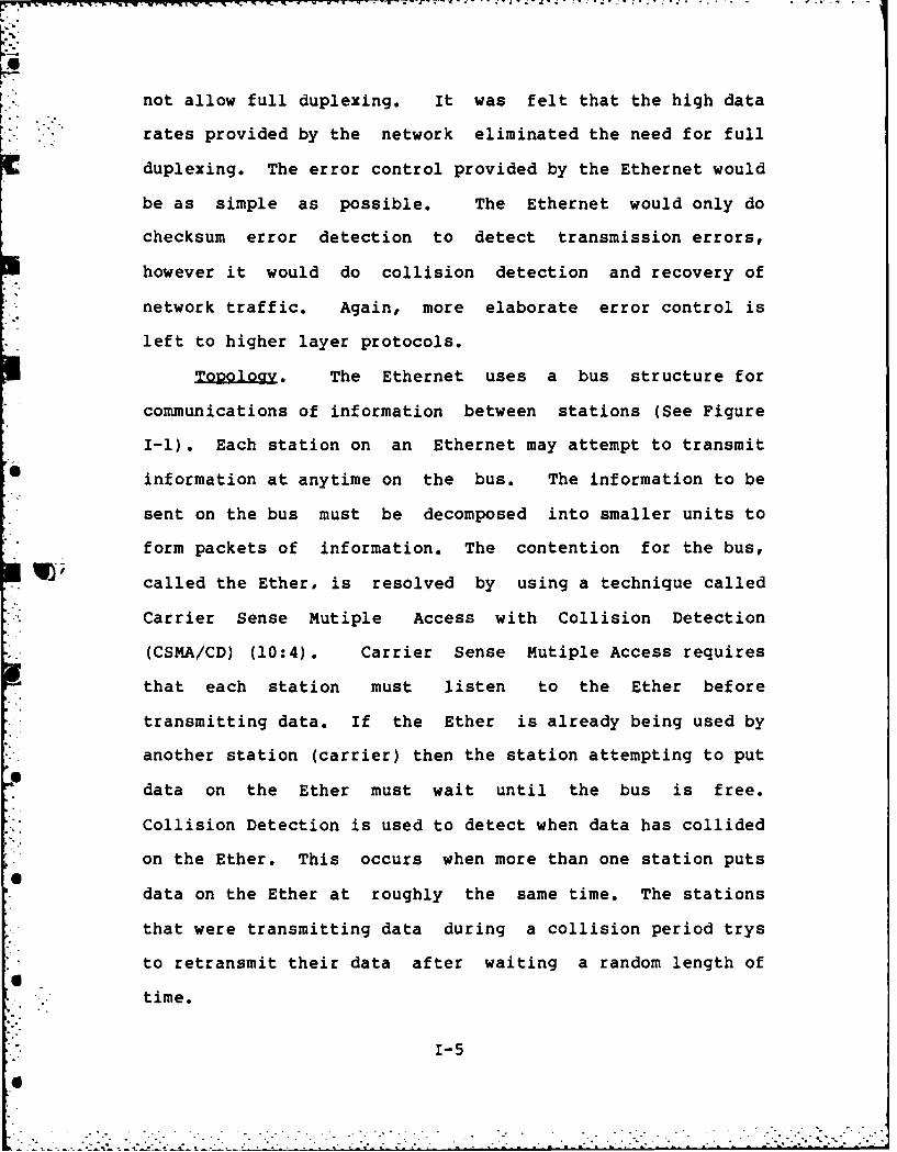
Ig29 ogy. The Ethernet uses a bus structure for
communications of information between stations (See Figure
I-1). Each station on an Ethernet may attempt to transmit
information at anytime on the bus. The information to be
sent on the bus must be decomposed into smaller units to
form packets of information. The contention for the bus,
W) called the Ether, is resolved by using a technique called
Carrier Sense Mutiple Access with Collision Detection
(CSMA/CD) (10:4). Carrier Sense Mutiple Access requires
that each station must listen to the Ether before
transmitting data. If the Ether is already being used by
another station (carrier) then the station attempting to put
data on the Ether must wait until the bus is free.
Collision Detection is used to detect when data has collided
on the Ether. This occurs when more than one station puts
data on the Ether at roughly the same time. The stations
that were transmitting data during a collision period trys
to retransmit their data after waiting a random length of
time.
" - 1-5
* -..- * *.* . * . * .* - *

and contention strategies used by competing systems in a
network for access to the shared medium. The data link
layer protocol specifies how the data is packaged for
transmission on the shared medium.
Design Goals. Many considerations were taken into
account in the design of the Ethernet (16:4). The Ethernet
is designed for use in office automation communications to
assist computer growth in an organization. The control of
the Ethernet and access to it would be designed so that no
one station could dominate the network. Criteria would be
set on the length an Ethernet could be extended to maintain
a consistent data rate throughout the network. A flexible
addressing scheme for station communications was also
considered. The addressing scheme would not only have to
allow station to station addressing, but also a station to a
group of stations, or a station to all the stations on the
network. One of the most important considerations in the
design of the Ethernet was to maintain compatibility between
Ethernet implementation. This would be accomplished by
building the communcations on the Ethernet in a layered
approach and outlining specifications for each layer.
There were several network processes that would not be
part of the Ethernet requirements (16:5). The Ethernet
would not handle security issues such as encryption of data
and measures to combat hostile users. Security measures to
handle these issues however, could be handled by higher
layer protocols using the Ethernet. The Ethernet also would
1-40" I

-7 7. -1
---,office has already installed a Xerox Ethernet local area
network. This network has Xerox office automation computers
such as workprocessors, workstations, laser printers, and
microcomputers connected to it,, The Program and Financial
Control office not only needs the computing power provided
by their Ethernet local area network, Jbut there is also a
need for using a mainframe computer for data processing. /
Therefore, the Program and Financial Control office is
planning to acquire a Digital Equipment Corporation VAX
11/780 mainframe computer with the Unix Berkeley 4.2BSD
operating system. They are also planning to connect the VAX
11/780 mainframe computer to their Ethernet local area
network.
r Ethernet sgun
The Ethernet local area network was developed by a
joint effort between Xerox, Intel, and Digital Equipment
corporations (16). The Ethernet architecture is composed of
the hardware and software specifications to facilitate
communications between computer devices (stations). The
International Standards Organization (ISO) developed a seven
layer architecture for communication between computers in a
computer network (65). Each layer of the architecture is
* built on the lower layers. The Ethernet architecture
encompasses the lower two layers of the ISO model, the
physical and data link layers.
9 _The physical layer protocol specifies the allocation
1-3
6i
* where a limited amount of computing power is needed. These
new computers that have been added to the office are
referred to as c. fice automation computers. The
introduction of all of these new computers to the office
created a need to share information among them. This need
brought about the development of the local area networks
technology.
Local area networks allow autonomous computing devices
the ability to share information., It is very advantageous
to setup a local area network when t ere are many different
computing devices in an office. A local area network allows
6 wordprocessors, workstations, and microcomputers to share
information and very costly resources such as printers,
plotters, and disk storage. However, a local area network
of office automation computers does not solve all of the
computerized needs of all offices. Some offices not only
need the onsite computer devices such as wordprocessors,
workstations, and microcomputers, but also the power of a
mainframe computer. Therefore, a local area network might
have to include provisions for exchanging of information
between an office's mainframe computer and its office
automation computers.
The Office of the Assistant Secretary of Defense
Comptroller (Program and Financial Control office) is an
organization which needs a local area network that contains
office automation computers and a mainframe computer for
information management. The Program and Financial Control -) -
1-2

,%
INTERFACING THE VAXl SING BERKELEY UNIX 4.28SD
N ETHERNET BASD XEROX NETWORK SYSTEMS
I. Introduction
Computers are now a part of many offices. Large
mainframe computers were first used in offices for numerical
calculations and daily transaction processing. However, the
mainframe computers were mostly used at night for processing
jobs in batch mode. Toda', >mainframe computers are
accessible online and are the mainstay of the computing
power offices use Although the mainframe computers are now
accessible online, they are not used for processing all of
the information that must be managed in an office.
Mainframe computers are used primarily by offices for
maintaining large databases and doing number crunching.
This is mainly because it is the most cost effect way to use
these very expensive computer systems.
The evolution of computers has produced new computer
devices that can be used in offices. Wordprocessing
computers enable secretaries to produce and maintanin
documents more efficiently. Workstation computers give
professionals tools that assist them in the performance of
their duties. Workstation computers are also used for data
processing. Microcomputers are used in special applications
I-i 'p

2. An Ethernet controller board for installation in
the Unibus of the VAX 11/780.
.4
3. An Ethernet Transceiver for connecting the VAX
11/780 to an Ethernet.
4. An Ethernet Transceiver cable for connecting the
Ethernet Transceiver to an Ethernet.
5. An Ethernet based Xerox Network System with at
least:
A. A Xerox File Server.
B. A Xerox Print Server.
C. A Xerox 8010 workstation.
D. The Xerox Clearinghouse Service.
outline DfThsi
This thesis concentrates on an investigation of those
protocols needed to allow a VAX 11/780, using the Berkeley
Unix 4.2BSD operating system, to communicate with Xerox
computer systems on an Ethernet local area network. Chapter
Two outlines the protocols that are required for interfacing
the VAX 11/780 and Ethernet based Xerox Network Systems.
Chapter Three presents the current status of those protocols .
that have, or have not, been implemented in support of
interfacing the VAX 11/780 and Ethernet based Xerox Network
Systems. Chapter Four presents a general design of the
1-15

Xerox Bulk Data Transfer Protocol, a protocol that is
required for interfacing with Xerox Network Systems but has
never been implemented for the VAX 11/780. Chapter Five
* presents an implementation and testing of the Xerox Bulk
*Data Transfer Protocol. Finally, Chapter Six specifies
conclusions reached in this investigation, along with
recommendations for future research efforts.
* This thesis also includes a number of appendices.
Appendix A contains Ethernet product line information.
Appendix B contains a SADT general design of the Xerox Bulk
Data Transfer Protocol. Appendix C contains a data
dictionary of terms used in Appendix B. Appendix D contains
a detail design of the Xerox Bulk Data Transfer Protocol
using structure charts. Appendix E contains a data
dictionary of terms used in Appendix D. Appendix F contains
a test plan for dynamically testing an implementation of the
*Xerox Bulk Data Transfer Protocci. Appendix G contains a
- list of the individuals and the organizations contacted
during the course of this investigation. Appendix H
contains an implementation of the Xerox Bulk Data Transfer
Protocol written in the IC' programming language.
1-16
II. ±&Q.~j Reguirement
Introduction
This chapter discusses those protocols that must be
implemented on the VAX 11/780, using the Berkeley Unix
4.2BSD operating system, to allow it to interface with
Ethernet based Xerox Network Systems. This chapter also
discusses the need the Program and Financial Control office
L has for the use of the TCP/IP protocols. First, an overview
of the ISO model for network structures is presented.
Second, an overview of the Xerox network structure as it
relates to the ISO model is presented. Third, a discussion
of the TCP/IP protocol requirements is presented. Finally,
the protocols are outlined that have to be implemented on
the VAX 11/780 to enable it to interface with Xerox Network
K Systems.
LSQ Model
Many different network structures exist for networking
and sharing computer systems. Each structure is composed of
functional areas called protocols. A protocol specifies theF: convention for the orderly exchange of information betweentwo computing elements over a communication path (49). Most
network structures use a layering of protocols. In a
layered protocol structure, each of the protocol layers has
to interface with the protocol layers above and below it,
except the highest and lowest layers.

The highest protocol layer is directly concerned with
providing services for users of a network system. Network
services such as electronic filing, printing, and mailing
* are performed by protocols implemented in the highest layer
of a network structure.
The lowest protocol layer specifies the access
strategies used for allowing computer systems to share a
common physical medium, that is the physical network.
Between the highest and lowest protocol layers are
other protocols which ensure a user request is sent and
received by other computer systems on a network. Each
computer system on a network must contain all the protocol
layers specified by a network architecture in order to
communicate with other systems on a network. This is
because each protocol layer of a network structure
communicates only with its peer protocol layer.
The ISO model is a layered protocol structure used by
many network structures. It was developed to assist network
interfacing by providing a standard for network structures.
The ISO model subdivides the functions of a network system
into seven layers (See Figure 11-1). This subdivision of
network functions simplifies the overall task of interfacing
systems on a network. The reason being the interfacing is
done in increments, hence the implementation of each
separate network function is less complicated.
11-2

Irrrr t. #-,-
-rr
.'
-
''.-
'
-
-
application layer layer 7
presentation layer layer 6
session layer layer 5
transport layer layer 4
network layer layer 3
data link layer layer 2
physical layer layer 1
Figure 11-1. ISO Model.
Physial~ Lyercx Prtcl The physical layer provides
mechanical, electrical, functional, and procedural
characteristics to establish, maintain, and release physical
connections (65:430). This includes the scheme used by a
network for allowing the use of the transmission medium.
Other issues which are covered by the physical layer are
constraints on the physical medium and location of computer
devices on a network.
DA&LayeriProtocol. The purpose of the data link
layer is to provide the functional and procedural means to
9 establish, maintain, and release data links between network
entities (65:430). A data link between devices on a networkcan be in one of two forms, connection oriented or
connectionless.
In a connection oriented method, a data link between
computer devices must first be initiated before data can be
sent over a communications link. Once data transfer has
11-3

been completed over a data link, the data link must be
terminated.
In a connectionless scheme, a single frame of data is
passed from one device on the network to another. The
connectionless scheme is described in the IEEE 802 Data Link
Control Protocol (35). There is no handshaking to ensure
data sent was received by the destination station when a
connectonless scheme is used. This scheme is normally used
on high transmission rate networks, such as local area
networks. The reliability that data will be received by a
device on the network, when a connectionless scheme is used,
is ensured by higher layer protocols of a local area
network.
The data link layer also addresses the issue of data
framing. Data framing specifies the field contents of a
frame of information to be transmitted on the network.
Fields are separated by control characters, or by specifying
the length for each field in a frame. A frame of
information usually contains the source and destination
device address fields, the data field, and the error check
field.
Network L Protocol. The network layer provides
routing and switching of information in a network system
(65:430). The network layer is composed of two sublayers.
One sublayer is concerned with network traffic for a local
network. The other sublayer is concerned with network
traffic between network systems, which is called an
internetwork, or internet.
11-4

The network layer, like the data link layer, may use a
connection oriented or a connectionless scheme for network
traffic routing and switching. In a connection oriented
scheme a logical link is established between the source and
destination devices on a network. Once a link has been
established, blocks of information called packets, are
transmitted from the source device to the destination
device. The link is not terminated until all packets
tramsmitted have been acknowledged by the destination
device.
In a connectionless scheme, packets are transmitted
e independently. This is known as datagram delivery. The
routing used to transmit individual packets may also be
different, because logical packet routes are not predefined.
This scheme allows for a simpler strategy for routing
packets. The reason being routing information, such as
state tables, do not have to be maintained.
TransaoLt Layer Ptocol. The transport layer is
concerned with the reliable and cost effective transfer of
data in the network (65:430). There are five types of
transport services: connection oriented, connectionless,
broadcast, multicast, and expedited (14:25).
A connection oriented service initiates, maintains, and
terminates a connection between transport layers of a
network system. A connection is not terminated until all
the information has been reliably tramsmitted between two
devices on a network.
11-5

A connectionless service provides the reliable transfer
of one packet of information between computer devices on a
network.
The broadcast service transfers a packet of information
to all computer devices on the network. This service does
not ensure that the packet broadcasted was reliably received
by all devices on a network.
The multicast service transfers a packet of information
to a group of computer devices on a network. This service
also does not ensure that the packet transmitted was
reliably received by all devices which make up a multicast
group.
The expedited service provides a means for exchanging
information between transport layers in a short time
periord. This is accomplished by limiting the packet size
when using this service.
The transport layer provides reliable transfer of data
through the use of certain functions. Some of the basic
functions used by a reliable transport layer are sequence
control, error detection and error recovery, and information
assembly/disassembly (14:27).
The sequence control function ensures that all the
packets, which makes up a block of information, were
received by a destination device on the network. This
function is carried out by assigning consecutive sequence
numbers to packets as they are transmitted. The sending
computer device's transport layer checks to make sure all
11-66"

the packets were received by keeping track of the sequence
numbers received by the destination computer device's
transport layer. If the destination computer device did not
receive all of the packets of an information block, then the
sending computer device transmits those packets which were
not received.
The error detection function is carried out by adding a
field to the transport layer packet for data validation,
such as a checksum or a cyclic redundancy check field.
Depending on the type of check field used for data
validation, the transport layer may also be able to do error
recovery. This can only be done with check schemes which
cannot only detect errors, but also detect where the errors
are in a packet of information.
The assembly function encapsulates data from the
session layer into transport layer packets. The disassembly
function concatenates the data fields of transport layer
packets to form an information block.
Session Laye 2 ro o. The session layer provides
control for binding and unbinding between two presentation
entities, as well as controlling the exchanging, delimiting,
and synchronizing of data between two presentation layers
(65:430). The binding control of a session allows two
presentation layers to communicate through a dialogue. The
unbinding control of a session is the means by which
communication between two presentation layers is terminated.
The presentation layers at either end of a dialogue
11-7
I7

controls the state of a session. One presentation layer
wanting to establish a dialogue with another presentation
layer does so by issuing a request to its session layer.
The session layer then establishes a path by which
communications between the requesting and the destination
presentation layers can carry on a dialogue. This path is
established through the use of the transport layer.
Once a communication path has been established by the
session layer. the presentation layers can carry on a
dialogue. The presentation layers use the structure the
session layer defines for data and message exchange.
The presentation layers terminate a dialogue by issuing
the appropriate message to the session layer. The session
I I~elayer then terminates the connection established by the
transport layer.
Presentation Laye.r ProtocolQ. The presentation layer
provides services which may be selected by the application
layer to enable it to interpret the meaning of data
exchanged (65:430). The presentation layer provides a
structuring of data that can be used by the application
layer to transfer information.
The application layer conveys to the presentation layer
the data structure it wishes to use to transmit/receive
information. The presentation layer then makes the
appropriate transformation of the data depending on whether
the data is being transmitted or received. If the data is
being transmitted, then it is transformed into a format
11-8
suitable for transmission by the session layer. If the data
is being received, then it is transformed from the session
layer format to the format specified by the application
layer.
Ap22.icatio.n Layeri £LxkQ&Q. The protocols of this
layer directly serve the end user by providing the
distributed information service appropriate to an
application, to its management, and to system management
(65:430). Application services that might be provided for
an end user are electronic filing, mailing, and printing.
System management tools at the application level might allow
collection of statistics on network operations and resource
usage information. This type of information can assist the
manager of a network system in configuration management,
resource management, and workload management of the network.
OyL~ryi~e3w. Xerox has developed a network structure that
not only allows interfacing with Xerox office automation
computers in a local area network environment, but also
allows the internetworking of Xerox Network Systems (XNS)
with other network systems. The Xerox network structure is
a layered protocol structure. The Xerox layered protocol
structure encompasses the network functions outlined by the
ISO model. The level zero protocols contain the protocols
for particular network systems. This is comparable to the
physical layer, data link layer, and the network layer of
H1-9

the ISO model which deals with a single network system. The
level one protocol is comparable to the network layer of the
ISO model that deals with internetworking of network
systems. The level two protocols are comparable to the
transport layer of the ISO model. The level three protocols
are comparable to the session and the presentation layers of
the ISO model. The level four protocols are comparable to
the application layer of the ISO model.
The Program and Financial Control office uses the
Ethernet at level zero of their Xerox Network System. Their
network system contains only Xerox office automation
equipment. All of the Xerox office automation equipment on
their network contains, at a minimum, level one to level
three of the Xerox network structure. Level four protocols
are also resident on Xerox office automation devices on
their network as appropriate. Therefore, in order for the
Program and Financial Control office to have the VAX 11/780
communicate with other devices on their network, it must
also contain the Xerox network structure.
The following discussion relates the Xerox network
structure to the seven layer ISO model. It is assumed, as
in the case of the Program and Financial Control office,
that the Ethernet is used at level zero for the transmission
of level one to level four protocols of the Xerox network
structure.
Physic.alJ Layer. The physical layer handles the
transmission/reception of Ethernet packets on the Ether.
11-10
This is accomplished by functional components that
produce/receive signals on/from the Ether. The functional
components are an encoder/decoder, synchronization
circuitry, tranceiver cable, carrier sense circuitry, and
the tranceiver (51:31). The encoder/decoder is usually
located on a controller board, which also contains the data
link layer. Each bit sent by the data link layer to the
physical layer is encoded using a Manchester encoding
scheme. This scheme merges the separate bit data and clock
signal into a single, self-synchronization serial bit stream
suitable for transmission on the coaxial cable by the
transceiver (51:96).
The controller board also contains circuitry which
creates/removes a 64 bit pattern before a data link layerr,.packet is transmitted/received (See Figure 11-2). This 64
bit pattern is called the preamble. The preamble has
alternating l's and 0's for the first 62 bits. The last two
bits of the preamble are set to l's. These two bits signal
the beginning of a packet. The preamble is sent through the
encoder to the tranceiver before the first bit of a data
link layer packet is sent. The preamble is discarded upon
receipt by the physical layer. The preamble is used for
synchronization to ensure data on the Ether is valid to all
stations on the network.
The transceiver cable connects the controller board to
the transceiver. The transceiver cable carries three
signals, and power to the transceiver. The three signals
11-ll

are the receive, transmit, and collision signals. The
transmit signal carries the encoded bits which are to be
placed on the Ether by the transceiver. The receive signal
carries the encoded bits received by the transceiver from
the Ether. This signal is sent to the decoder and also a
carrier sense circuitry at the controller. The carrier
sense circuitry signals the data link layer that data is
available. However, the data link layer must check the
address field of the packet to determine if the packet is
addressed to the station. The collsion signal is activated
by the transceiver when it detects an input transition
before 160 nanoseconds has elasped.
i jo i 10 11 o0...i o,01 1 0 11 11 1ugh level --
Figure 11-2. Preamble Encoding
Source: 51:98
The physical layer of the Ethernet not only addresses
the requirements of connecting a station to the Ether, but
also how an Ethernet system can be configured. Certain
limits are placed on an Ethernet configuration to ensure a
11-12

Check3sum
Length Level one
Trans oort Control I Packet Typo - Error Addremng and Delivery
Cesination Networlt
Destination Host
Destination Socket
Source Network
Soure HMs
Source Socket
Error Number
Error Parameter Level two
Error Protocoi
Copy of portion of offending packetContents
Figure II-10. Error Packet
Source: 54:33
11-26

operation. A request operation requests routing information
*about other networks in the internetwork from an internet
router. The networks that information is requested about is
specified in the object network field(s). An internet
router responses to a request operation by specifying, in
the internetwork delay field(s), how many internetwork
router "hops" it takes to get to the network(s) specified in
the object network field(s). If a internetwork delay field
was set to 16, then a requested network in the object
network field could not be reached by the internetwork
router. The internetwork router sets the operation field to
response, and sends the network information back to the
source host address.
I= Error Protocol. The Error Protocol is used
for reporting the occurrence of an error during the
transmission of internet packets. The Error Protocol
specifies an internet packet format (See Figure II-10). An
internet packet with the packet type set to 2 octal denotes
an error packet. Any socket within a host may generate an
error packet in response to some error condition. The error
packet is addressed to the source network, host, and socket
which caused the error condition. The error number field
represents these conditions (See Table II-1). The error
parameter field, of the error packet, may be set to indicate
the type of parameters to use to determine the kind of error
which occurred. The contents field contains a portion of
the internet packet which caused the execution of the Error
Protocol.
11-25

Checksum
Lengt Level one~
Transport Control I Packet Type * RI Addressing and Delivery
Destination Network
Destination Hoat
Destination Socket
Source Network
Source Host
Source SocketOperation
Level twoObMect Network Routing Inf nafion Protocol
interntwork Delay
Object Network
Internetwork Delay
Contents
Figure 11-9. Routing Information Packet
Source: 54:26
11-24
P P- .- ~..- S- - -- - ~ - :--- - -
Source host 0 aI
Source rocessintempcetr
Oedestinationhost~~ntwr a g ewri nefc
Fiuestinatio nteNetworkA
Sorewr 5]4:7 eethost
Encaps11-23o

structure. The five protocols are part of what Xerox calls
its Internet Transport Protocols. The five protocols of the
transport layer provides reliable service by performing
functions such as retransmission, sequencing, duplicate
suppression, and flow control of internet packets (54:2).
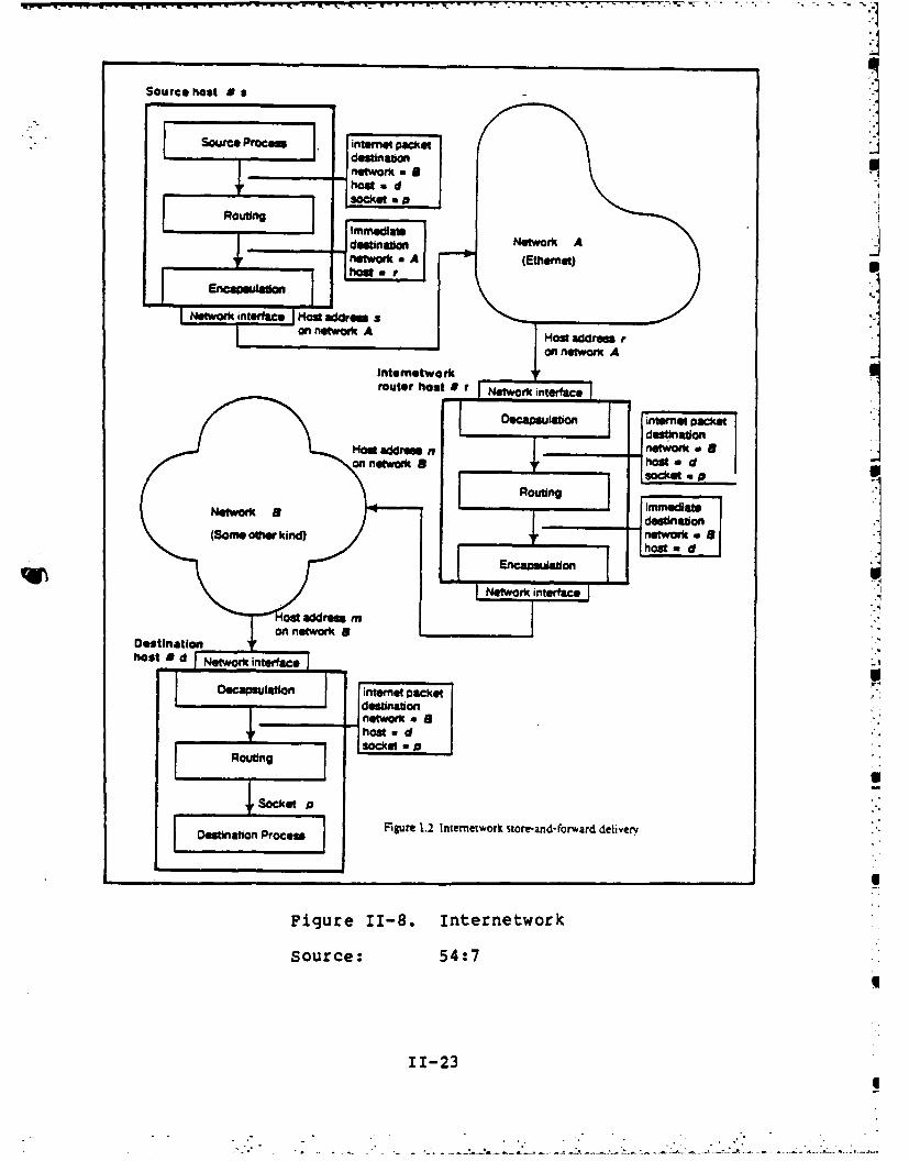
X o ting Information Protocol. The logical
function of switching (routing) internet packets between
sockets (that are on the same host), between sockets and
networks (the host is the source or destination of the
packet), and between networks themselves (in an internetwork
router) is abstractly captured in a router (54:5). Each
host system on an internetwork contains a router. Host
systems on the internet which are responsible for
store-and-forward delivery of internet packets between
networks also contains what is called an internet router
(See Figure 11-8).
The Routing Information Protocol provides a means for
host routers and internetwork routers to exchange routing
information. Each router on an internetwork maintains a
routing table of network addresses used by the resident
host. An internetwork router also maintains addresses of
all the networks it is connected to.
The Routing Information Protocol specifies an internet S
packet format (See Figure 11-9). An internet packet with
the packet type field set to 1 octal denotes a routing
information packet. The operation field of a routing
information packet designates either a request or response
11-22

"hop" count of 15, the packet is discarded. The maximum
number of networks an internetwork packet can traverse is
16.
The packet type field is specified by the transport
layer protocols. It defines the type of internet packet
being transmitted. This field is not interpreted by the
Internet Datagram Protcol, but rather by the transport layer
protocols at a destination station.
The address information of an internet packet contains
source and destination network, host, and socket addresses.
The network address specifies the unique address of one of
the networks which makes up an internetwork. The host
address specifies the unique address of one of the host
systems (stations) on an internetwork. The socket address
specifies a unique socket within a host system. A socket is
a uniquely identified object within a host, to which
internet packets can be delivered, and from which internet
packets may be transmitted (13:2). An internet packet can
be addressed to a host system, to a group of host systems
(multicast), or to all the host systems on the internetwork
(broadcast).
X rans ot L . Xerox Network Systems provide
five protocols for the reliable transmission of information
on the internetwork. The five protocols are Routing
Information Protocol, Error Protocol, Echo Protocol,
Sequence Packet Protocol, and Packet Exchange Protocol.
These protocols make up level two of the Xerox network
11-21

0 1
ChecksumControl Lengml Level one
Transport Control I Packet Type Addressing and Delivery
Oetination Network
Debeination Destinabon How
Network Address Hee
Oetination Socket
Source Network
source S ce N
Network Address
* Source Socket
Level two
Undefined
(0 to W bytes of tanspent data) Oaln
* Potential Garbage Byte
0 1 7
Hop Count Packetrype
Figure 11-7. Internet Packet
Source: 54:15
11-20
. ..6, , . . . - . . -: - : ." "i - . - - . " . - . - -,

function of the Internet Datagram Protocol is to address,
route, and deliver standard internet packets, each of which
is treated as an independent entity with no relation to
other internet packets traversing the system (54:14). An
internet packet is indentified as the data field of an
Ethernet packet when the type field of an Ethernet packet
* has a value of 3000 octal.
The Internet Datagram Protocol specifies the format of
the internet packet (See Figure 11-7). The internet packet
format is composed of three areas: control information,
address information, and data. The control information of
an internet packet contains the checksum, length, transport
control, and the packet type fields. The checksum field is
* - used to detect whether the other fields of an internet
packet is valid. If an internet packet is found to be
erroneous, it is discarded without error reporting. Error
reporting should be handled by the transport layer. The
length field specifies the size of internet packets in
bytes. An internet packet may contain a garbage byte to
insure that all internet packets are of an integral size of
16 bit words. The garbage byte is not included in the
length field.
The transport control field is used to keep track of
how many networks an internet packet has transversed. Each
time an internet packet is being transmitted to another
network, the network router increments the "hop" count. If
a network router receives an internet packet which has a
11-19

xsNetwork Lve
- . Local Networking AA AsRpi t2 th Etherne. The
Ethernet uses a connectionless scheme for routine packets.
The network dedicates itself to routing one packet at a
time. However. it does not ensure that the packet will be
transmitted correctly. or at all. Once a packet has been
placed on the Ethernet, every station on the network will
receive it. The destination address field of an Ethernet
packet determines the destination station(s) of a packet.
The Ethernet provides three forms of addressing, station to
station, multicasting, and broadcasting (10:13). In station
to station addressing, the destination station field of an
Ethernet packet designates the destination station. In
multicasting addressing, the destination address field of an
Ethernet packet designates a group of stations that makes up
a multicast group. In broadcasting addressing, the
destination address field of an Ethernet packet is set to
zero, this indicates that the packet is for every station on
the network.
XN Network L
Internetworking as Al 1o Xerox Network
System. Xerox Network Systems use a datagram technique for
delivering internetwork packets. The datagram technique is
a connectionless scheme for internetwork traffic routing and
switching. The scheme for handling internetwork packets is
outlined in the Xerox Internet Datagram Protocol (54). The
11-18
- . -- - -.v.'" .-? .- -
TransmitFrafn RcevFr
msemrble Aramte star receiving
yell deferring on. 0 dnrciig
no yes
startdWAassemblefame toUw e
trnmisond ne? ejs~trpoes rm~cie rcsccvkigDu no rjsntrreoeno) (noin aaLn ee~~aeQenzn
n os w eFigure 1-6. EterntDaaLikLae
Sorc:163
YIfyes M1u-17frm

physica~fmulicas bit6 octem Destination
Frm Oct= SeuecI
Lce Bype wiciithiOccecam Lransmcred
Figure 11-5. Ethernet Packet
Source: 16:20
11-16

adds the frame check sequence field when constructing
packets to be sent to the physical layer. The frame check
sequence field is used to perform a cyclic redundancy check
(CRC) to detect errors in a packet received from the
physical layer. This check is performed using all fields of
the packet except the CRC field. The function used for
generation of the CRC field and validation of the other
fields is the same one used in the Autodin-II network (25).
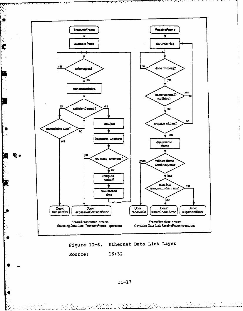
The other function which makes up the data link layer
on the Ethernet is called link management (See Figure 11-6).
Link management involves two task, transmitting/receiving
packets to/from the physical layer and handling data
collisions. The packets communicated between the data link
and physical layers are sent 1 bit at a time. The data link
layer can send a packet to the physical layer for
transmission only when the physical layer is not receiving
data from the Ether. The transmission of a packet between
the data link and physical layers is clocked, therefore no
handshaking is required before each bit is transmitted.
However. when the data link layer is transmitting a packet
to the physical layer. it must monitor the transmission
checking for the occurrence of a collsion. If a collision
occurs, the data link layer determines when to try
retransmitting the packet.
11-15

Coaial Cable Segment
Transceiver Cable Coa=W CableSmM mau
Transceiver A ConncionSttUn to Coaxial Cable
(100 max per sement)
Figure 11-3. A Single Cable Segment
Source: 51:79
segment 1
Repeater
Segment 2
Figure 11-4. Two Cable Segments
Source: 51:79
11-146"

consistent 10 Mbps transmission rate, and a limit on the
propogation delay of information on the Ether. For
instance, a cable segment cannot exceed 500 meters (See
Figure 11-3). It also cannot contain more than 100
transceivers.A
The Ethernet does provide a way to connect cable
segments, by using a repeator device (See Figure 11-4). A
repeator device repeats the signals from one cable segment
to another. However, the maximum number of repeators
allowed within the path of any two stations is two (51:77).
XNS Data LkLave.. The data link layer uses a
connectionless scheme for flow of data on an Ethernet. The
data link layer is composed of two main functions which
allows the transmission/reception of information to/from the
physical layer. called data encapsulation and link
management (16:19). Data encapsulation involves taking
information supplied by the network layer and creating an
Ethernet packet for the physical layer to transmit on the
Ether. Data encapsulation also involves decapsulation of
data out of an Ethernet packet supplied by the physical
layer. The decapsulated data is sent to the network layer.
The Ethernet provides a variable size packet for data
transmission on the Ether (See Figure 11-5). The packet
structure is represented in octets. Each octet represents 8
bits. An Ethernet packet can have from 512 bits to 1200
bits in the data field. The data encapsulation function
11-13: :: ::

Table II-1
Error Types
Error Number Description
0 An unspecified error is detected atdetected at destination.
1 The checksum is incorrect, or thepacket has some other seriousinconsistency detected at destination.
2 The specified socket does not exit atthe specified destination host.
3 The destiantion cannot accept thepacket due to resource limitations.
1000 An unspecified error occurred beforereaching destination.
1001 The checksum is incorrect, or thepacket has some other serious inconsistency before reaching destination
qW 1002 The destination host cannot bereached from here.
1003 The packet has passed through 15internet routers without reaching itsdestination.
1004 The packet is too large to beforwarded through some intermediatenetwork. The Error Parameter fieldcontains the length of the largestpacket that can be accomodated.
Source: 54:34
11-27

.r r -. - - . r -: . < - : X' V' W. ' , b . .Z V' -V.. . - -. : , . i
SProtocol. The Echo Protocol is used to
ensure a host system exist on the internetwork. The Echo
Protocol specifies an internet packet format (See Figure
II-li). An internet packet with the packet type set to 3
octal denotes an Echo Protocol packet. The operation field,
of the echo packet, can be set to echo request or echo
reply- If a host wants to determine the existence of
another host, then an echo packet must be constructed with
the operation field set to echo request, and the data field
set to information to be echoed. When a host system
receives an echo packet with the operation field set to echo
request, it will set the operation field to echo reply and
transmit the packet back to the source host system. When
the host system, which initiated an echo packet with echo
request and data to another host, receives an echo packet
with echo reply and the original data sent to the
destination host, then the host system does exist on the
internetwork. However, if the an echo packet with echo
reply is not received from the destination host of an Echo
Protocol exchange, then the host does not exist on the
internetwork.
11-28
- .. .'. :.. .-. ~..---'.. .~.

Checksum
Length Level oneTransport Control Packet Type - Echo Addressng and Delivery
Destination Network
Detnton Most
Destination Socket
Source Network
Source Most
Source Socket-Operation
Level twoEcho Protocol
Data to be echoed or being echoed
* Figure II-li. Echo Packet
Source: 54:35
11-29

NSegene Packet Prtoo. The Sequenced
*Packet Protocol provides a reliable way of transmitting
internet packets. This is achieved by establishing a
connection between a send device's transport layer and a
receiving device's transport layer. Therefore, the
Sequenced Packet Protocol uses a connection oriented scheme
for the reliable transmission of internet packets. The
Sequenced Packet Protocol transmits informaton that is
received from the session layer. The transport layer
assembles the data it receives into internet packets. Each
packet is sent to a destination station with a sequence
number. The first packet sent has a sequence number of
zero, and successive packets sequence numbers are one higher
then the packet sent before it. Acknowlegement of received
packets by the destination station is sent to the source
station by sending an echo of the packet received. If the
sequence number of a packet echoed to the source station was
higher than expected, then packets were lost or in error.
Therefore, the lost or error packets must be retransmitted
by the source station.
The Sequenced Packet Protocol specifies an internet
packet format (See Figure 11-12). An internet packet with
packet type set to 4 octal denotes a Sequenced Packet
Protocol packet. The connection control field is 8 bits.
The system packet bit, bit 0 of the connection control
field, is used to determine which station the internet
packet is for. The send acknowledgement bit, bit 1 of the
11-30

Checksum L
Length Lel one
Transport Control Paclet T-e SP Addressing and Delivery
Destination Network
Desination Host
Desination Socket
Source Network
Source Host
Source SocketConnection Control I Datastream Ty""
Source Connection ID L l two
Destinaltion Connection ID Sequenced Packet Protocol
Sequence NumberAcknowledge Number
Allocation Number
Level threeControl
Data
0 4 7 15
Jil 111Reserved Datastresm Type
I End.of-message
Attention
Send Acknowledgement
Sysem Packet
Figure 11-12. Sequenced Packet
Source: 54:38
11-31
*.-- : .- -- - * -. ..- . ,d,,..

connection control field, tells the destination station to
acknowledge every packet received. The attention bit, bit 2
of the connection control field, tells the destination
station to notify the session layer of arrived packets. The
end of message bit, bit 3 of the connection control field,
tells the destination station to convey to its session layer
that it is at the end of a message stream of packets.
The datastream type field is not used by the Sequenced
Packet Protocol. The field is transmitted from the source
sequence packet protocol to the destination sequence packet
protocol, where it is sent to the session layer for
interpretation. This field is used for communications
between session layers of a connection.
The source and destination IDs indentifies the sockets
of the source and destination stations that established a
connection.
The sequence number field keeps track of the number of
packets sent in either direction on a connection. The
destination station can also send sequenced packets to the
source station. Therefore, the connection provides a two
way packet communications path. The sequence number field
is used by the destination station to deduce the order of
packets, to acknowledge them, to suppress duplicates, and to
specify flow control information (54:40).
The acknowledge number field specifies the next
sequence packet the destination station is expecting from
the source station.
11-32
*

The allocation number field specifies the number of
packets that will be accepted at a destination station.
During the operation of a connection, this number may go up,
but not down.
The data field contains session layer data.
SPacket E Protocol. The Packet Exchange
Protocol is used for requesting service from a socket. The
Packet Exchange Protocol specifies an internet packet format
(See Figure 11-13). An internet packet with the packet type
set to 5 octal denotes a Packet Exchange Protocol packet.
The ID field specifies the socket that service is requested
of. The client type field specifies the service requested.
The response to a request is sent to the destination socket
address. If the response sent to the destination socket
address has the ID and client type fields of the original
request, then the data field contains a valid response from
the service socket.
X NSessi nti La.yer Protool. Although, Xerox claims
that it does not implement the session layer of the ISO
model, in fact it really does implement the session layer of
the ISO model. It was stated in the Xerox Internet
Transport Protocols document that Xerox has no protocol
corresponding to layer 5 of the ISO model, the session layer
(54:9). However. the Xerox Courier Protocol, which was
stated in the same document as implementing the presentation
layer. also implements the session layer. The Xerox Courier
11-33

ChecksumlLenoth Level one
Transport Control 1 Packet Type PE Addressing and Delivery
Destination Network
Destination Ho
Destination Socket
Source Network
Source Host
Source Socket
I Level two
client Type Packet Exchange Protocol
Figure 11-13. Packet Exchange Protocol Packet
Source: 54:50
11-34
..

-Y I7 "
Protocol implements two types of session layer services, one
that sets up a session for data exchange, and another that
provides transaction processing services.
The establishment of a session for exchanging of data
between two sockets is referred to as layer one of the
Courier Protocol. Layer one defines a block stream that can
carry blocks of arbitrary binary data between system
elements (sockets) (55:3). A block of data consists of data
Ibits which are multiple of 16 bits. First, a session must
be established between two Courier Protocols. This is
achieved by establishing a connection at the transport
layer. using the Sequenced Packet Protocol. Once a
connection has been established, the version of Courier to
be used must be agreed upon by the sending and receiving
* stations. After the version of Courier to be used has been
* agreed on, the data blocks are transmitted between the
* sending and receiving stations by using the Sequenced Packet
Protocol. After all the data has been sent between the
sender and receiver. the sending station transmits an "end"
packet to the receiving station. Once the receiving station
has received all of the data blocks, it transmits an
"end-reply" packet to the sending station. After the
sending station receives the "end-reply" packet from the
receiving station, it then sends another "end" packet to the
* receiving station to terminate the session.
- Courier also provides a session service for transaction
processing. This service is layer three of the Courier
11-35

Protocol. Layer three defines a message stream capable of
carrying service requests (that is, call messages) and
replies (for example, return and abort messages) between
system elements (55:3). Courier defines four message types
for transaction processing: call, reject, return, and
abort. The call message invokes a socket program. The
reject message is sent back when the requested socket
program can not be executed. The return message is sent
back to acknowledge the successful completion of a socket
program. The abort message is sent back when an error
condition occurs doing the execution of the socket program.
The Packet Exchange Protocol, of the Xerox Internet
Transport Protocols, provides service for remote socket
calls, which is what this type of session service is.
X~Presentation Laer The functions of the
presentation layer are also contained in the Courier
Protocol. Layer two of the Courier Protocol implements the
presentation layer functions. Layer two defines an object
stream capable of carrying structured data (for example,
booleans and cardinals) between system elements (sockets)
(55:3). An object stream is composed of data objects. Each
data object represents a data typing such as integer,
string, or array. Each data object is encoded into multiple
bits of 16. The data objects are then sent to layer one of
Courier for transmission, by using the Sequenced Packet
Protocol of the Xerox Internet Transport Protocols.
Remember. layer one of Courier breaks data objects into data
11-36
blocks for transmission. Therefore, when the data blocks
are received at the destination station, they are assembled
into data objects and decoded by the layer two Courier
Protocol to transform them into their correct data type.
Xerox has also developed a dialogue that application
layer protocols can use to transfer large amounts of
information, called bulk data. This dialogue is defined by
the Xerox Bulk Data Transfer Protocol (56). The Xerox Bulk
Data Transfer Protocol defines a dialogue that the sender
and the receiver of bulk data can use to contact each other,
as well as controlling the transfer of the bulk data.
I= Ap21.icatio.n ILayer. Xerox Network Systems have many
applications available to the user. Some of the
applications available are file service, print service, and
electronic mailing. File service allows workstations on the
network to store and retrieve information on mass storage
areas called file servers. The use of file servers on an
internetwork by workstations also allows sharing of
information stored on the file servers between workstations.
Print service allows workstations to share printers on the
network. Print service allows users to send files from
their own workstation, or files located on file servers, to
a printer on the network for printing. Electronic mailing
11-37

allows mailing of documents, files, and messages to other
workstations on the network.
TCP/IP ReQuirements
The Program and Financial Control office is part of the
Department of Defense (DoD). DoD has adopted its own
protocols for the internetworking of packet switched network
systems. DoD uses the Internet Protocol (IP) at the network
layer. DoD also uses the Transmission Control Protocol
(TCP) at the transport layer. These two protocols are
commonly referred to as TCP/IP. TCP/IP was developed by the
Defense Advanced Research Projects Agency (DARPA) (46, 6,
7). It has been mandated that the use of DoD standard
host-to-host protocols (TCP/IP) is mandatory for all DoD
packet-oriented data networks which have a potential for
host-to-host connectivity across network or subnetwork
boundaries (38). Therefore, the Program and Financial
Control office must comply with this mandate. W
Xerox Network Systems use the Xerox Internet Transport 1Protocols (ITP) and the Xerox Internet Datagram Protocol
(IDP) at the transport and network layers. Xerox Network
Systems use these protocols for routing internetwork traffic
and for providing reliable transmission of higher layer.1
protocols information. Therefore, the Program and Financialo
Control office is negotiating with Xerox to provide a device
on a Xerox internetwork which will accept TCP/IP internet
packets and encapsulate them into ITP/I'3P internet packets
11-38
6q.
for routing. However, the Program and Financial Control
office would like the VAX 11/780 to be accessible to
networks in the interwork using TCP/IP. Therefore, TCP/IP
must also be implemented on the VAX 11/780 along with higher
layer protocols supported by TCP/IP such as File Transfer
Protocol (FTP), Simple Mail File Transfer Protocol (SMTP),
and the Terminal/Host Protocol (TELNET) (6).
Summax
The ISO model for network architectures defines a
layering of protocols. This model was developed as a
standard to assist in the internetworking of network
systems. The layering of protocols outlined by the ISO
model is commonly used for the design and implementation of
network structures.
Xerox has develop a network structure based on the
layering of protocols defined by the ISO model. The Xerox
network structure has five levels, beginning with level
zero. Level zero corresponds to layer one, layer two, and
layer three that deals with local area networks, of the ISO
model. Level one corresponds to layer three of the ISO
model that deals with internetworking. Level two
corresponds to layer four of the ISO model. Level three
corresponds to layers five and six of the ISO model. Level
four corresponds to layer seven of the ISO model.
The Program and Financial Control office has
requirements, as outlined in Chapter one, for using a VAX
11-39

11/780 system to interface with a Xerox Network System. The
interfacing will occur at level four of the Xerox network
structure. The interfacing with level four applications
requires the existence of levels three thru zero of the
Xerox network structure on the VAX 11/780, because the Xerox
network structure is layered. Therefore, all four levels of
the Xerox network structure must be implemented on the VAX
11/780 if the Program and Financial Control office
requirements' of interfacing a VAX 11/780 with their Xerox
Network System is to be met.
The Program and Financial Control office, being part of
the Department of Defense, is mandated to use the TCP/IP
protocols at the network and transport layers for
internetwork communications. Therefore, an implementation
of TCP/IP for the VAX 11/780, using Berkeley Unix 4.2BSD, is
alse required.
The Program and Financial Control office is, first,
interested in the interfacing of the VAX 11/780 with
Ethernet based Xerox Network Systems. Second, interested in
having a capability of interfacing with other networks via
the TCP/IP protocols. Hence, the rest of this thesis is
geared toward the accomplishment of the goal of interfacing
the VAX 11/780 with Ethernet based Xerox Network Systems.
The interfacing of Xerox Network Systems and networks using
TCP/IP is a thesis effort in itself. Since the Program and
Financial Control office would like the VAX 11/780 to
eventually interface with host systems on TCP/IP networks,
11-40

Table 111-4
XNS Level Two Summary
XNS Level Two A B C I N
Sequenced Packet F F N F FProtocolEcho Protocol F F N F FPacket Exchange Protocol N F N F FError Protocol P F N F FRouting Information P F N F FProtocol
Definition of Symbols:
A = Advanced Computer Corporation B = BridgeCommunications
C = 3Com Corporation I = InterlanN = Network Research Corporation F = Full
ImplementationP = Partial Implementation N = No
Implementation
XNS level one is specified by the Internet Datagram
Protocol. XNS level two is specified by the Echo Protocol,
the Error Protocol, the Sequenced Packet Protocol, the
Packet Exchange Protocol, and the Routing Information
Protocol.
Bridge Communications and Network Research Corporation
claim to fully implement the XNS level one and the XNS level
two protocols for the VAX 11/780 with the Berkeley Unix
4.2BSD operating system.
Interlan claim to fully implement the XNS level one and
the XNS level two protocols, but they do not have an
111-13
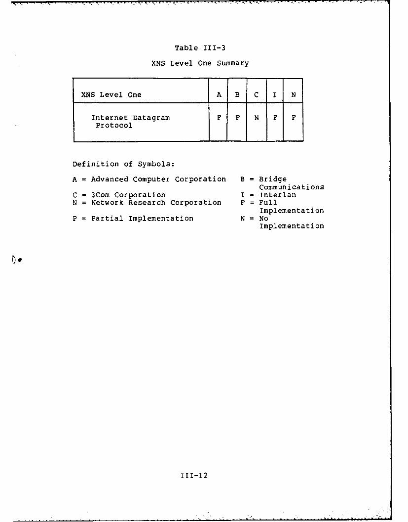
Table 111-3
XNS Level One Summary
XNS Level One A B C I N
Internet Datagram F F N F FProtocol
Definition of Symbols:
A = Advanced Computer Corporation B = BridgeCommunications
C = 3Com Corporation I = InterlanN = Network Research Corporation F = Full
ImplementationP = Partial Implementation N = No
Implementation
111-12

Currently. there is no device driver software for the
Berkeley Unix 4.2 BSD operating system. However, by the time
this report is release device driver software for the
Berkeley Unix 4.2BSD operating system should be available.
Interlan and 3Com also have designed Ethernet
controller boards for the VAX 11/780, but they do not have
device driver software for the Berkeley Unix 4.2BSD
operating system. However, the Berkeley Unix 4.2BSD
networking facilities contain device driver software for the
3Com and the Interlan Ethernet controller boards. An
interesting statement about the performance of the 3Com and
the Interlan controller boards said they both have identical
throughput characteristics with Berkeley Unix 4.2BSD, but
neither have proven entirely satisfactory (31:12). The
reasons being: 1) data has to moved between the VAX Unibus
and the 3Com Ethernet controller board a word at a time and
2) the Interlan Ethernet controller board uses a significant
amount of +5 volt power and it does not perform the Ethernet
CRC checksum.
XNS Levels' Qn A" Two. Level one of the XNS
architecture structure contains the network layer function
of the ISO model concerned with internetworking systems (See
Table 111-3). Level two of the XNS architecture structure
contains the transport layer functions of the ISO model (See
Table 111-4). Specifications for XNS level one and XNS
level two are outlined in the Internet Transport Protocols
document (54).
111-ll

area networking functions of the ISO model (See Table
111-2). This research is interested in an XNS network
environment with the Ethernet providing level zero service,
because this is one of the requirements of the OSD P&FC
office. The Ethernet Version 1.0 specification outlines the
protocols for connecting to and establishing an Ethernet
network (16).
Table 111-2
XNS Level Zero Summary
XNS Level Zero A B C I N
Ethernet Specification F F F F F
Definition of Symbols:
A = Advanced Computer Corporation B = BridgeCommunications
C = 3Com Corporation I = InterlanN = Network Research Corporation F = Full
ImplementationP = Partial Implementation N = No
Implementation
Bridge Communications and Network Research Corporation
have designed Ethernet controller boards and device driversI
for the VAX 11/780 with the Berkeley Unix 4.2BSD operating
system.
Advanced Computer Communications (ACC) has also
designed an Ethernet controller board for the VAX 11/780.
II1-10
A

network server maintains the routing table used by internet
routers by implementing a protocol similar to the XNS
Routing Information Protocol.
The OSD P&FC office requires the interfacing of a VAX
11/780 with Xerox office automation equipment. This
interfacing would allow desired services between the VAX
11/780 and Xerox office automation equipment to occur such
as electionic filing, mailing, and printing. The protocols
that perform these services in a Xerox network environment
are in level four of the XNS architecture structure. The
XNS levels of protocols below XNS level four would also have
to be implemented to meet the requirements of interfacing
the VAX 11/780 with Xerox office automation equipment,
because the protocols that compose the XNS architecture are
layered.
A level by level discussion of which protocols of the
XNS architecture structure have, or have not, been
implemented for the VAX 11/780 is presented. This
discussion is based on the information gathered from the
Ethernet product line search, and the networking information
presented on the Berkeley Unix 4.2BSD operating system.
The implementation of TCP/IP on the VAX 11/780 is also
discussed, because this is another requirement of the OSD
P&FC office.
NSLevel Zero. Level zero of the XNS architecture
structure contains the physical, data link, and the local
111-9

the networking facilities' SOCK_STREAM socket type. The
User Datagram Protocol (UDP) is a specification for a
datagram delivery service. UDP uses the networking
facilities' SOCK_DGRAM socket type to accomplish this task.
The Berkeley Unix 4.2BSD operating system also provides
support for the DARPA application layer protocols SMTP,
TELNET, and FTP (4). The Simple Mail Transfer Protocol
(SMTP) provides an electronic mail service. The TELNET
protocol provides a virtual terminal service. The File
Transfer Protocol (FTP) performs electronic filing on an
internet.
Ethernet a =NS w Support. The Berkeley Unix
4.2BSD networking facilities contain software for connecting
a VAX 11/780 to an Ethernet, and two network servers based
on the XNS protocols.
The networking facilities contain hardware interface
layer software for three 10Mb/s Ethernet controller boards.
The three 10Mb/s Ethernet controller boards are the 3Com
3C300. the Interlan NII010A, and the Proteon proNET
(33:13-14).
The network facilities network servers that are based
on XNS protocols are called "couried" and "routed" (34:34).
The "couried" network server provides a remote procedure
capability using the XNS Courier Protocol. The "routed"
111-8
information about a hardware device such as the hardware
device name, the local network host number where the
hardware device resides, and the network address of the
interface routine to a hardware device. Delivery and
reception of packets from a hardware device are managed by
information in the hardware interface layer data structure
such as a queue of packets to transmit and a queue of
packets received from a hardware device. The hardware
interface layer data structure also stores information
pretaining to the hardware device network operations such as
the number of packets received, the number of packets
transmitted, the number of collision packets, the number of
damaged packets sent, and the number of damaged packets
received at a hardware device. Berkeley Unix 4.2BSD has a
routine that takes the information stored in the hardware
interface layer data structure about a hardware device's
network operations and provides various statistics on the
network operations of the hardware device.
DARPArtocols Support. The Berkeley Unix 4.2BSD
provides support for the DARPA standard Internet protocols
IP, ICMP, TCP, and UDP (34:31). The Internet Protocol (IP)
is a specification for the network layer functions of the
ISO model. The Internet Control Message Protocol (ICMP) is
the control protocol associated with IP that is used to
convey error and status information to Internet users (5).
The Transmission Control Protocol (TCP) is a specification
for the transport layer functions of the ISO model that uses
111-7

manipulated by the user interface routines of the networking
facilities (18:9).
The Communication Prot l Lae. The
communication protocols layer manages the data structure
that is associated with the use of a particular protocol
(for example, the XNS Internet Datagram Protocol). The data
structure that defines the use of a protocol contains four
pieces of information; the protocol identification,
protocol-to-protocol communications, user-to-protocol
communications, and protocol utility routines (18:12). The
protocol identification contains information such as the
socket type that supports a protocol, the protocol
identification number, and the protocol family (i.e XNS).
The protocol-to-protocol communications data define those
routines used to pass information to protocols above and
below a given protocol. The user-to-protocol communications
define the routine used to interface with the socket type a
protocol is using. The protocol utility routines define the
timing mechanisms used to determine the state of a protocol.
tHardware interface L . The hardware
interface layer is responsible for encapsulation and
deencapsulation of any low level header information required
to deliver a message to its destination, in addition to6
manipulating a hardware device (18:13). The hardware
interface layer manages the data structure associated with
using a hardware device on a network system. The hardware
interface layer data structure contains network addressing
111-6
6-' -

concept of a reliable datagram service for the delivery of
* ''I information. The SOCKSEQPACKET socket provides a reliable
sequential transmission of information. These socket types
can be used to support the implementation of protocols that
make up the network and transport layers of a network
structure.
The Berkeley Unix 4.2BSD networking facilities have
routines designed to assist in the manipulation of sockets
(9:29-31). There are routines that allow the creation and
naming of sockets. Routines exist that provide listening
and answering services for sockets. Routines exist that
establish connections between sockets. Routines exist that
provide a means of sending and receiving information to/from
sockets. Finally, routines exist to disconnect one or both
sides of a connection between sockets.
Internal truJtxr. The internal structure of the
networking facilities provided by Berkeley Unix 4.2BSD is
outlined in the 4.2BSD Networking Implementation Notes
document (18). This document specifies that the internal
structure of the networking facilites are divided into three
layers; the highest layer called the socket layer, the
middle layer called the communication protocols layer, and
the lowest layer called the hardware interface layer.
Socket Layer. The socket layer is composed of
those data structures used to manage sockets and their
interconnections. Most of the information stored in the
socket management data structures are supplied and
111-5
0

The Berkeley Unix 4.2BSD operating system also contains
implementations of the protocols that make up the Department
of Defense (DOD) standard for internetworking as outlined by
the Defense Advance Research Projects Agency (DARPA). The
DOD internetworking protocols were implemented using the
networking facilites of the Berkeley Unix 4.2BSD operating
system.
Berkeley Unix 4.2BSD also contains software
Iiaplementations related to connecting a VAX 11/780 to an
Ethernet, as well as protocols related to the XNS
architecture structure.
User Intface. The user interface provided by the
Berkeley Unix 4.2BSD networking facilities is centered on
the concept of a socket. A socket is a bidirectional
endpoint of communications which is "typed" by the semantics
of the communications it supports (18:8). Sockets are the
means by which information is exchanged between processes in
a network environment. Currently, Berkeley Unix 4.2BSD
networking facilities define five socket types; they are
SOCK_DGRAM, SOCK_STREAM, SOCKRAW, SOCKRDM, and
SOCKSEQPACKET (9:28). The SOCKDGRAM socket uses the
concept of a datagram delivery of information. The
SOCKSTREAM socket uses the concept of a virtual circuit for
the delivery of information. The SOCKRAW socket allows
direct access to the network layer functions without a
scheme at the transport layer to ensure the reliable
transmission of information. The SOCKRDM socket uses the
111-4
S%

Ethernet product line, and 3) Ethernet product lines specify
interfacing of other systems with XNS networks, thereby
revealing possible future additions of other systems to the
OSD P&FC network. The Ethernet product line literature
search information is located in Appendix A.
The literature search on the networking facilities of
the Berkeley Unix 4.2BSD operating system is in four areas:
1) the networking facilities of the Berkeley Unix 4.2BSD
operating system, 2) any sofware support for TCP/IP, 3) any
software support for the Ethernet, and 4) any
implementations of the XNS protocols.
This chapter then presents an overview of the
implemented XNS and TCP/IP protocols.
The chapter concludes with a summary of the XNS and the
TCP/IP protocols that have, or have not, been designed and
implemented on the VAX 11/780 with Berkeley Unix 4.2BSD.
BeklyUnix 4.2BSD0eaigSse
The XNS protocol structure that must be designed for
the VAX 11/780 to enable it to interface with Xerox
networking devices at the application layer will be under
the Berkeley Unix 4.2BSD operating system, as required by
the OSD P&FC office. The Berkeley Unix 4.2BSD operating
system defines a framework for supporting network
applications. The networking facilities available under
Berkeley Unix 4.2BSD have a user interface and a documented
internal structure to assist network designers in the design
and implementation of network systems.
111-3

Table III-i
XNS Architecture Structure
Level Four (Application Layer)
Filing ProtocolMailing ProtocolPrinting ProtocolOther Applications Support Protocols
Level Three (Presentation and Session Layers)
Courier ProtocolBulk Data Transfer Protocol
Level Two (Transport Layer)
Sequenced Packet ProtocolEcho ProtocolPacket Exchange ProtocolError ProtocolRouting Information Protocol
Level One (Network Layer)
Internet Datagram Protocol
Level Zero (Data Link and Physical Layers)*!
Ethernet Specification
1
. III-2
S
III. Prtcl Implementation Sau
Tntroduction
As outlined in the previous chapter, a layered
architecture structure is required for networking with Xerox
Network Systems. All five levels of the Xerox Network
System (XNS) protocols must be developed on the VAX 11/780
to meet the requirements specified by the Office of the
Secretary of Defense (OSD) Program and Financial Control
(P&FC) office (See Table III-1). The requirements specified
by the Program and Financial Control office involves the
interfacing of the VAX 11/780 with Xerox office automation
equipment at the application layer.
I)' A literature search was performed to determine which
communications protocols of XNS have already been designed
and implemented for the VAX 11/780 with the Berkely Unix
4.2BSD operating system, the system the OSD P&FC office is
acquiring. The results of the literature search is composed
of two parts: 1) information on Ethernet specific product
lines, and 2) information on the networking facilities of
the Berkeley Unix 4.2BSD operating system.
A literature search of Ethernet product lines is
performed for three reasons: 1) the OSD P&FC office has an
Ethernet at level zero of their Xerox network environment,
2) most implementations of the XNS protccols are part of an
II

1-W %7 ". '-L -k
research was also performed to determine the extent that
TCP/IP was implemented on the VAX 11/780.
The next chapter reviews information gathered during a
literature search that was performed to determine which
protocols of the Xerox Network System and TCP/IP have
already been implemented for the VAX 11/780 using the
Berkeley Unix 4.2BSD operating system.
11-41

implementation for Lhe Berkeley Unix 4.2BSD operating
system. However. they point out that their implementation
is in the C programming language. This should make it
easier to transport their implementation to systems with the
C programming language, such as the VAX 11/780 with the
Berkeley Unix 4.2BSD operating system.
ACC has a full implementation of the XNS level one
protocol. They also have a partial implementation of the
XNS level two protocols. ACC does not have a full
implementation of the Routing Information Protocol and the
Error Protocol, which are part of the XNS level two
protocols. They also have not implemented the Packet
Exchange Protocol, another XNS level two protocol. ACC's
implementations of the XNS level one and the XNS level two
protocols should be available for the Berkeley Unix 4.2BSD
operating system, by the time this report is released.
LS Level Three. Level three of the XNS architecture
structure contains the session layer and the presentation
layer functions of the ISO model (See Table 111-5).
Specifications for XNS level three are outlined by the XNS
Courier Protocol (55) and the XNS Bulk Data Transfer
Protocol (56).
ACC has a partial implementation of the XNS level three
protocols, with a full implementation of the Courier
Protocol and no implementation of the Bulk Data Transfer
Protocol. Currently. their implementation of XNS level
three is only for Unix V7 operating systems. However, they
111-14
n

should have an implementation for the Berkeley Unix 4.2BSD
operating system by the time this report is released.
Table 111-5
XNS Level Three Summary
XNS Level Three A B C I N
Courier Protocol F N N N NBulk Data Transfer N N N N NProtocol
Definition of Symbols:
A = Advanced Computer Corporation B = BridgeCommunications
C = 3Com Corporation I = InterlanN = Network Research Corporation F = Full
ImplementationP = Partial Implementation N = No
Implementation
Berkeley Unix 4.2BSD has a partial implementation of
the XNS level three protocols, with a full implementation of
the Courier Protocol and no implementation of the Bulk Data
Transfer Protocol. The Courier Protocol implemented as part
of the Berkeley Unix 4.2BSD networking facilities is offered
as a network server. However, the Berkeley Unix 4.2BSD6
networking facilities do not implement XNS level one and XNS
level two in support of the Courier Protocol network server.
XN Level Four. Level four of the XNS architecture
structure contains the protocols and standards found in the
111-15
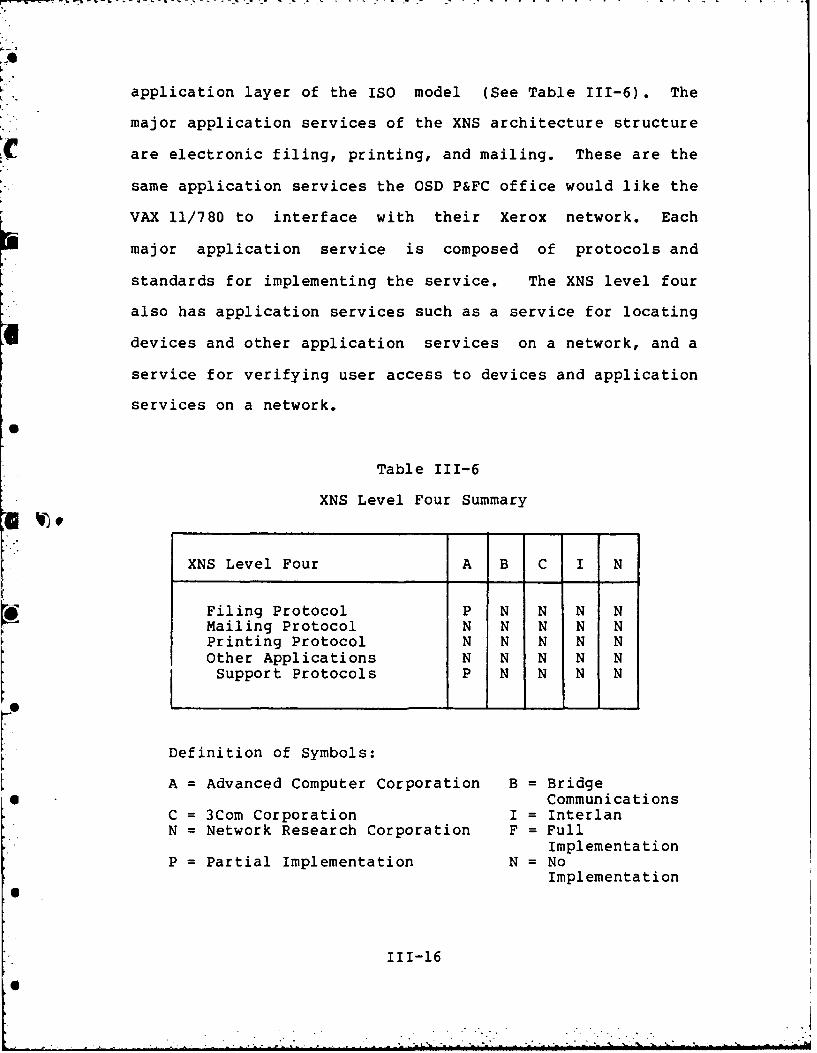
application layer of the ISO model (See Table 111-6) . The
major application services of the XNS architecture structure
C are electronic filing, printing, and mailing. These are the
same application services the OSD P&FC office would like the
VAX 11/780 to interface with their Xerox network. Each
major application service is composed of protocols and
standards for implementing the service. The XNS level four
also has application services such as a service for locating
I devices and other application services on a network, and a
service for verifying user access to devices and application
services on a network.
Table 111-6
XNS Level Four Summary
XNS Level Four A B C I N
EFiling Protocol P N N N NMailing Protocol N N N N NPrinting Protocol N N N N NOther Applications N N N N NSupport Protocols P N N N N
Definition of Symbols:
A = Advanced Computer Corporation B = BridgeS Communications
C = 3Com Corporation I = InterlanN = Network Research Corporation F = Full
ImplementationP =Partial Implementation N =No
Implementation
111-16

An effort was made to acquire the protocols and
standards of the electronic filing service. This was done
for two reasons: 1) this is one of the services the OSD
P&FC would like a VAX 11/780 to perform with Xerox network
devices and 2) the electronic filing service is the basis
for transmitting information in a network environment.
Xerox, however, has decided that their electronic filing
service protocols and standards are still in a period of
evolution and are not stable enough for release to the
public. The only major application service released to the
public by Xerox is their electronic printing service.
The Xerox electronic printing service was released to
the public in a package called Interpress. The Interpress
package contains the protocols and standards of the Xerox
electronic printing service, other application layer
protocols and standards used by the electronic printing
service, and all the protocols of the XNS levels' one
through three. The protocols and standards of the
electronic printing service are in these documents: the
Interpress 82 Reader's Guide (52), the Introduction to
Interpress (BY), the Interpress Electronic Printing Standard
(57), the Character Code Standard (58), and the Printing
Protocol (62). The other application layer protocols and
standards used by the electronic printing service are the
Time Protocol (60), the Authentication Protocol (61), the
Clearinghouse Entry Formats (63), and the Clearinghouse
Protocol (59).
111-17
. ...6 " ; " / _ " - - • _ ' . . ' ' -

ACC has a partial implementation of the Clearinghouse
Protocol. They have used this implementation, along with
the other XNS protocols they have implemented, to design
their own electronic filing service (2). In fact, Xerox has
asked them to develop an interpretor which is to be used for
file transfers between the Xerox file service and the ACC
file service.
TCP/IP Requirement. The OSD P&FC office has as a
requirement the use of the DARPA TCP/IP protocols at the
network and transport layers of the ISO model. 3Com has
implemented TCP/IP on the VAX 11/780. They also have a
partial implementation of the DARPA protocols for file
transfer, virtual terminal service, and electronic mailing.
However, the Berkeley Unix 4.2BSD networking facilities have
a full implementation of the DARPA protocols TCP, IP, UDP,
and ICMP. The Berkeley Unix 4.2BSD networking facilities
also provides support for the DARPA application layer
protocols FTP, SMTP, and TELNET.
Summr
The literature review performed reveals that XNS
levels' zero through two are implemented for the VAX 11/780
with the Berkeley Unix 4.2BSD operating system. It also
reveals that Berkeley Unix 4.2BSD has a full implementation
of TCP/IP, along with the UDP, ICMP, FTP, SMTP, and the
TELNET DARPA protocols.
The literature review also reveals that there are not
111-18
• . .. °I

W V
full implementations of XNS level three and the electronic
filing protocol of XNS level four. The electronic filing
protocol uses XNS level three, hence a full implementation
of XNS level three is required. The only protocol of XNS
level three that has not been implemented is the Xerox Bulk
Data Transfer Protocol. Therefore, the next chapter
presents a general design of the Xerox Bulk Data Transfer
Protocol.
F.
11I-19

IV. General Desgn Q A XAM Protocol
Introduction
The full range of XNS protocols that support and
provide the electronic filing, printing, and mailing
services on a Xerox Network System have not been implemented
for the VAX 11/780 with the Berkeley Unix 4.2BSD operating
system. However. some of the protocols that make up the XNS
network structure have been designed and implemented for the
VAX 11/780 with the Berkeley Unix 4.2BSD operating system,
as outlined in the previous chapter (See Tables 111-2 thru
111-6). The XNS architecture structure is layered,
therefore it requires the lower levels of the XNS structure
to exist before higher levels, such as electronic filing,
printing, and mailing, can be implemented.
The previous chapter pointed out that the protocols
which compose the XNS levels zero through two have been, or
will soon be, designed and implemented for the VAX 11/780
with the Berkeley Unix 4.2BSD operating system. It was also
pointed out that the Advanced Research Corporation (ACC) had
a partial implementation of the XNS level three protocols.
Level three of the XNS architecture structure is composed of
two protocols, the Courier Protocol (55) and the Bulk Data
Transfer Protocol (56). ACC has a full implementation of
the Courier Protocol, but no implementation of the Bulk Data
Transfer Protocol.
IV-l

Level four of the XNS structure, that includes
electronic filing, printing, and mailing functions, are
dependent directly on the use of the Courier Protocol and
the Bulk Data Transfer Protocol of XNS level three.
Therefore, a design and an implementation of the Bulk Data
* Transfer Protocol for the VAX 11/780 with the Berkeley Unix
4.2BSD operating system is required, if XNS level four
applications are to be implemented as desired by the Program
and Financial Control office.
This chapter begins with a brief overview of the
Courier Protocol, because it is the means by which
communications is specified by the Bulk Data Transfer
Protocol. Also, an overview is presented on the Xerox Bulk
Data Transfer Protocol. Finally, a general design of the
Xerox Bulk Data Transfer is discussed.
60 4The Xerox Courier Protocol provides session and
presentation support, as outlined by the ISO model, for
application protocols on a Xerox network. The Courier
* Protocol provides this support through the use of remote
procedure calls. Remote procedure calls allow network users
to execute programs located on remote host systems on a
0 Xerox Network System. The Courier Protocol facilitates the
construction of distributed systems by defining a single
request/reply or transaction discipline for an open-ended
0 set of higher-level applications protocols (55:1).
IV-2
Courier is designed to assist developers of network
services. A network service designer can view a network
service as a program that can be accessed by any remote host
system on a Xerox Network System. The network service
program is composed of procedures that perform primitive
functions of a network service. This is analogous to a
program developed in a high level language that is composed
of subprograms which perform functional tasks.
For example, an electronic printing network service
program might be composed of procedures that spool a file to
a printer, delete a file from a spooled printer queue, and
change the priority of files waiting to be printed in a
spooled printer queue. The electronic printing network
service is advertised as a complete service. A print
service request is carried out for a user of a network by
issuing the appropriate remote procedure calls to the
electronic printing program located at a remote printer.
The Courier Protocol is composed of three layers, the
block stream, the object stream, and the message stream (See
Figure IV-l). The block stream layer defines how the
Courier message and data stream is demarcated and
transmitted between established sockets on a Xerox Network
System. The object stream layer defines the data types that
Courier support. Some of the data types Courier support are
cardinal, string, integer, array, and record. The message
stream defines the message types that can be used for
communication between requestors and providers of services
on a Xerox Network System.
IV-3

- ~ ~A
Layer One MESSAGE STREAM(Call. Return. Abort. etc.)
Laye Two OBJECT STREAMLaye Two(Boolean. Cardinal. etc.)
LayerThree BLOCK STREAMLayerThree(Block)
Figure IV-l. The Courier Layered Structure
Source: 55:3
Courier. like the XNS architecture structure, has a
layered structure where the higher layers depend on the
lower layers. Courier layer three (the message stream) uses
the constructs provided by Courier layer two (the object
stream) to create calls to and interpret returns from remote
procedures. Courier layer one (the block stream) ensures
that Courier layer two (object stream) information is
transmitted between host systems on a Xerox Network System.
The Courier Protocol uses the Xerox Sequenced Packet
Protocol (54) for the reliable transmission of block stream
data.
Since, ACC has already implemented the Courier
Protocol, the detail specification of the object stream and
the block stream layers are not discussed. A detailed
discussion of the object stream and the block stream would
be needed if a design and an implementation of Courier were
being presented. However, what is discussed in detail is
Courier layer three, the message stream.
Courier defines four message types: the call message,7
IV-4

the reject message, the return message, and the abort
message (55:23). Requestors of network services uses the
call message to initiate the execution of remote procedures
on a Xerox Network System (See Figure IV-2). The response
to issuing a call to a remote procedure is returned by
either a reject message, a return message, or an abort
message. The Courier Protocol specifies that a user process
can only have one call message outstanding at any given time
(55:24).
Active PassiveSystem
CALL procedure, arguments Element
(caant~ ________________________ RemoteRETURN results
ABORT error, arguments
Figure IV-2. The Courier Model
Source: 55:2
The call message has a structure that is composed of a
program number. a version number, a procedure value, and
procedure arguments. The program number specifies the
network service program a requestor wants to execute. The
version number specifes the version of a network service
program a requestor wants to execute. The procedure value
specifies the procedure of the network service prcgram a
requestor wants to execute. The procedure arguments specify
the arguments a requestor is supplying to the procedure of
IV-5

the network service program. All of the procedure arguments
passed to a remote procedure must use the data typing
specified for the remote procedure by the network service
program.
The reject message is used by a network service program
to denote that a call to a remote procedure was rejected.
The return of a reject message from a network service
program means the execution of a remote procedure was not
attempted. The reject message specifies five standard
reasons why a call to a remote procedure was rejected
(55:25-26):
1. A program number specified by a call message
does not designate an existing network service
program.
2. A version number specified by a call message
is not implemented by a network service
program. If this reject message is returned,
the network service program also returns to
the caller of a remote procedure the lowest
and the highest version of the network service
program it supports.
3. A call message sent to a network service
program specified a procedure not supported by
the network service program.
IV-6
4. A call message does not have the expected
procedure arguments for a remote procedure.
5. For reasons other than the ones discussed
above which prevent a network service program
from initiating the execution one of its
procedures.
The return message specifies the results from executing
a remote procedure call. A return message is sent only when
a remote procedure executes successfully. The results
returned by a remote procedure are outlined by a network
service program. just as the procedure arguments to a remote
procedure are outlined by a network service program. The
results returned by a remote procedure are data typed using
the formats specified by Courier layer two, the object
stream.
The abort message is returned when an error occured
during the execution of a remote procedure. The network
service program defines appropriate error conditions for
each procedure that composes a network service program.
Each error condition is given a numeric error value, which
is used to signal the occurrence of a particular error.
Therefore, the abort message returns an error value that is
used to decoded the error condition that occurred during the
execution of a remote procedure. The abort message may in
addition to returning an error value, also return
parameters. These parameters are usually the procedure
IV-7
arguments passed to a remote procedure, via a call message,
that caused the generation of an abort message.
The Xerox Bulk Data Transfer Protocol is the means by
which application services on a Xerox Network System, such
as file service and print service, transfer large amounts of
information. The Xerox Bulk Data Transfer Protocol
standardizes the mannner in which the sender and receiver of
bulk data make contact with one another; how bulk data is
demarcated when transfered on the Courier connection between
them; and how the transfer can be aborted; if necessary by
either party (56:35) .
This protocol is an extension of the Courier Protocol.
r The Courier Protocol is designed for calling and receiving
status messages, or return arguments, from remote
procedures. En other words, it is designed only for
initiating a network service, such as electronic filing or
printing. The Courier Protocol is not designed for the
transfer of the actual bulk data that an electronic filing
or printing network service requires. Xerox has specified
how this task is performed between system elements on a
Xerox Network System in the Xerox Bulk Data rransfer
Protocol.
Like the Courier Protocol, the Xerox Bulk Data Transfer
Protocol is designed to assists designers of network
services. The Bulk Data Transfer Protocol assisc designers
IV-8

D-fl52 953 INTERFRCING THE VAX 11/788 USING BERKELEY UNIX 42BSD 2/2AND ETHERNET BASED X..(U) AIR FORCE INST OF TECHWRIGHT-PRTTERSON BFB OH SCHOOL OF ENGI.. E BERNARD
UNCLRSSIFIED DEC 84 AFIT/GCS/ENG/84D-4-VOL-i F/G 9/2 NLEEmnEEEmhhhEEImmmmEEEEEmmmEIllll~lEllllEEIEIIIEIIEEEEEEE
X010
lO 1111202
0 1112-
1111 iiiIL25II1.
MICROCOPY RESOLUTION TEST CHARTNATIONAL BUREAU OF STANDARDS- 1963-A

of network services by providing a standard dialogue between
system elements on a network that participate in the
transfer of bulk data. The Xerox Bulk Data Transfer
Protocol views the transfer of bulk data requires
communication between three system elements: the initiator,
the sender. and the receiver.
The initiator receives and acts upon a request for the
transfer of bulk data. For example, a user on a workstation
* requesting a file be sent to a print server would be
serviced by an initiator. The sender sends bulk data
requested to a specified destination. For example, a file
service sending a file to a designated print service. The
receiver accepts bulk data sent to it and acts upon it. For
- - -example, a print service receiving bulk data from a file
server that is to be printed.
Depending on where the initiator, the sender, and the
receiver of bulk data is located on a network, and the bulk
data request itself, determines the type of bulk data
transfer required. The Bulk Data Transfer Protocol supports
three forms of bulk data transfers: third-party, immediate,
and null (56:36). A third-party transfer is performed when
* the bulk data to be transmitted is not located at the
initiator host system, and it is not destined to be sent to
the initiator host system. Therefore, the communications
required to transmit the bulk data is between three host
systems, the initiator host, the sender host, and the
receiver host.
IV-9
An immediate transfer is performed when the bulk data
to be transmitted is either located at, or destined to be
sent to the host system that received a request for a bulk
data transfer (i.e. the initiator host system). The
communications required to transfer the bulk data is between
two host systems, the initiator host system and either the
sender host or the receiver host.
A null transfer is performed when a bulk data request
requires that no data is actually sent. For instance, a
request to create an empty file on a file service device.
The communcations for this type of bulk data transfer is
between two host systems, the initiator host and either the
sender host or the receiver host.
The communications between the initiator, the sender,
and the receiver is carried out mainly through the use of
Courier remote procedure calls. The initiator determines
the type of bulk data transfer that is needed for each bulk
data request it receives, and issues the appropriate remote
procedure call(s) to the sender and/or the receiver. The
sender has a remote procedure called Produce, which
retrieves the bulk data requested at a system element and
transmits it to another system element as designated by the
initiator. The receiver has a remote procedure called
Consume, which accepts bulk data from a system element
designated by the initiator.
The Produce and Consume remote procedures are not
generalized procedures that can be used for all bulk data
IV-10

transfers. These two remote procedures are application
specific for each network service application, just as the
application specific initiator of a network service is. The
Xerox Bulk Data Transfer Protocol outlines the functions the
initiator of a network service, and the application specific
remote procedures, Produce and Consume, must perfom to
ensure a standard and orderly exchange of bulk data.
General Designf h Xerox Da Data Protocol
The previous section gave the motivation for the use of
the Xerox Bulk Data Transfer Protocol, that being to assist
network designers in the transfer of bulk data between
system elements on a network system. This is achieved by
outlining communication standards between system elements
that participate in the transfer of bulk data. This section
concentrates on a general design of the Xerox Bulk Data
Protocol. The general design maps out the communications
among the initiator of a bulk data request, the Produce
remote procedure, and the Consume remote procedure.
The general design of the Xerox Bulk Data Transfer
Protocol requires the use of a technique that can represent
the communications among the initiator of a bulk data
request, the Produce remote procedure, and the Consume
* remote procedure. The Structured Analysis and Design
Technique (SADT) (15. 48, 50), Data Flow Diagrams (44:139),
and the Hierarchy Plus Input Process Output (HIPO) (44:48)
0 technique are all techniques that can be used to represent
the relationships between components of a system.
IV-11
%%6

The general design of the Xerox Bulk Data Transfer
Protocol is presented using the Structured Analysis and
Design Technique. This general design technique was chosen
for three reasons: 1) it provides a top down design
structure, 2) it represents the design graphically, while
highlighting the components of a design, and 3) it shows the
relationships between objects and activities of a system
(44:134).
The general design presented can be used as a blueprint
for implementing support for bulk data transfers required by
application services on a Xerox Network System. The full
Bulk Data Transfer Protocol must exist on each host system
on a Xerox network that can initiate, produce, and consume
an application service's bulk data.
Host systems on a Xerox network that only retrieve an
application service's bulk data at the local host system,
and sends it to a designated host system on the network,
need only implement the Produce remote procedure of the Bulk
Data Transfer Protocol.
Host systems on a Xerox network that only accept bulk
data sent to it, need only implement the Consume remote
procedure of the Bulk Data Transfer Protocol.
Host systems on a network that can produce and consume,
but not initiate, an application service's bulk data must
implement the Produce and the Consume remote procedures of
the Bulk Data Transfer Protocol.
* An application service uses its application specific
IV- 12
Bulk Data Transfer Protocol for the transmission of
' .N '~information that require a bulk data transfer. The
application specific Bulk Data Transfer Protocol can be
viewed as a complete system, where a bulk data request is
input to the system, and the result of the bulk data request
is the output of the system (See Figure IV-3). The heart of
the Bulk Data Transfer Protocol is the communications and
data transfers among the initiator of a bulk data request,
the Produce remote procedure, and the Consume remote
procedure (See Figure IV-4).
2M InitiatL. The initiator receives a request for
performing a bulk data transfer (See Figure IV-5). The bulk
data request must be parsed to extract information such as
the name, the request type, and the destination of the bulk
data (See Figure IV-5 SADT All). This information is used
to find the source and the sink (destination) addresses of
the host systems that will participate in the bulk data
transfer (See Figure IV-5 SADT A12 and SADT A13). The
initiator address, the source address, the sink address, the
request type, and the bulk data name are used to initiate
the appropriate type of transfer needed to transmit the bulk
data (See Figure IV-5 SADT A14).
The type of bulk data transfer used depends on where
the bulk data is located, where it is destined, and the
request type of the bulk data request (See Figure IV-6 SADT
A141). A null bulk data transfer is used when a bulk data
IV-13
'6 " "° " " -, .'". ' '

t
I0
I. I
Ii
F cj~
~0W2**
C.) *~ U
.-.. ~. ..-- W2 iii :4
Lw ~ Id
r~4B II
I..
9.
£1 0U
II 4
it 0
9.
40 _
i
I
Iv- 14
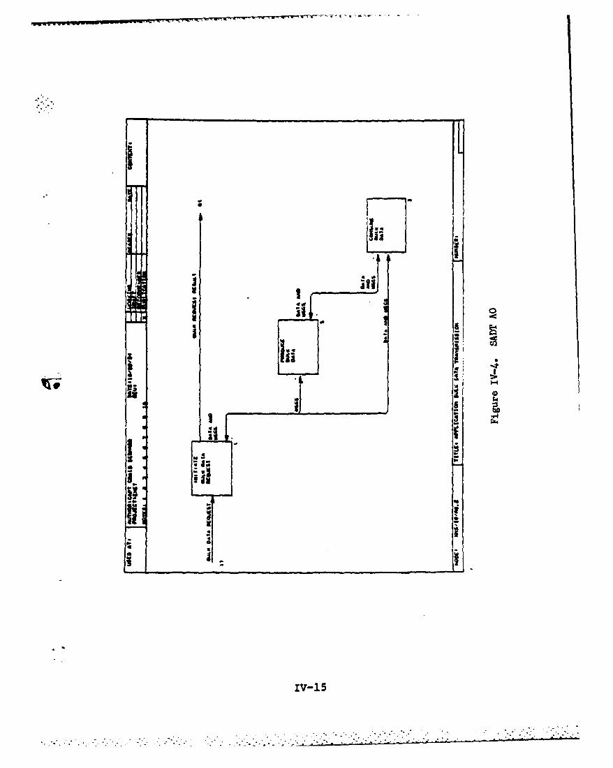
I*
'IiiV-
I
I .4'. 4 jI
iw~s 4
£511
4; I
2 4,
U IlI
I Ia
Iiii aS
4
40
4 4
-
IV-15
~

It *IV 131
949
'Ii
iv-()

!ii ai
i
* -,
El i
'a 3IV--?
. . 3... S:. F" . .. . / - ... i I I 1
request type specifies the creation or emptying of a file,
and the bulk data is not located at the initiator address
(See Appendix B SADT A143). An immediate bulk data transfer
is used when the source address or the sink address of the
bulk data is the same as the initiator address (See Figure
IV-6 SADT A.144). A third-party bulk data transfer is used
when neither the source address nor the sink address is the
same as the initiator address (See Figure IV-6 SADT A145).
A local bulk data transfer is used when the source address
and the sink address of the bulk data is the same as the
initiator address (See Figure IV-6 SADT A142).
The Xerox Bulk Data Transfer does not address the issue
of the local transfer of bulk data. It probably does not
address this issue because only one system element is
involved, that system being the host system where the bulk
data request was received. Therefore, there is no
requirement for communication between system elements of an
application service to achieve the data transfer. The bulk
data transfer takes place using an application service
procedure at the local host system, without the need to use
a Courier connection for communication and data transfer.
However. in the case of the null, immediate, and
third-party bulk data transfers, a Courier connection is
used for communication and the transfer of bulk data among
the initiator, the Produce remote procedure, and the Consume
remote procedure. Once the type of bulk data transfer is
determined, communcation between the initiator, and the
IV-1 8

appropriate Produce and/or Consume remote procedures, is
carried out. This communication specifies the role(s) the
initiator has assigned to the Produce and/or Consume remote
procedures in order to accomplish a bulk data request.
The initiator can assign one of four roles to the
Produce and the Consume remote procedures: null, immediate,
passive, and active. The null role specifies that the
remote procedure is to participate in a null transfer of
bulk data. The immediate role specifies that the remote
procedure is to participate in an immediate transfer of bulk
data. The active or passive role specifies that the remote
procedure is to participate in a third-party transfer of
bulk data. The Produce and the Consume remote procedures
must honor all four roles an initiator can assign to them,heif they are to comply with the Bulk Data Transfer Protocol
(56:41).
BU" Transfer. A null role is assigned to a
Produce remote procedure when it is decided that a null
transfer is to be used, and the bulk data request is for a
task such as creating a file (See Appendix B SADT A1431). A
null role is assigned to a Consume remote procedure when it
is decided that a null transfer is to be used, and the bulk
data request is for a task such as emptying a file (See
Appendix B SADT A1432).
Immeia Transfer. An immediate role is assigned
to a Produce remote procedure when it is decided that an
immediate transfer is to be used, and the destination of the
IV-19

bulk data is the initiator address (See Appendix B SADT
A1441). An immediate role is assigned to a Consume remote
procedure when it is decided that an immediate transfer is
to be used, and the destination of the bulk data is not the
initiator address (See Appendix B SADT A1442).
ThirdPaty TraTransfer. The initiator calls both
the Produce and the Consume remote procedures simultaneously
when a third-party transfer is used to transmit bulk data
(See Appendix B SADT A145). The source address of a
third-party transfer is used to call the Produce remote
procedure. The sink address of a third-party transfer is
used to call the Consume remote procedure. The initiator
decides the complimentary passive or active roles that the
Produce and the Consume remote procedures are to perform.
The Prduce Remote P. The Produce remote
procedure communicates with two system elements. It
directly communicates directly with the initiator, and
indirectly with the Consume remote procedure (See Figure
IV-4). The initiator activates the Produce remote procedure
supplying arguments. The main argument supplied defines the
role Produce is to play in a bulk data transfer (See Figure
IV-7 SADT A2). The bulk data located at the Produce host
system is retrieved, when Produce is to participate in an
immediate or third-party transfer (See Figure IV-7 SADT
A21). The Produce remote procedure returns the status of
performing its assigned role via the initiator Courier
connection.
IV-20

bulk data. The first process, called SendData (See Appendix
E-55), sends bulk data on a connection established by a
Courier call message. The second process, called AcceptData
(See Appendix E-2), receives bulk data from a connection
established by a Courier call message. These two processes
are not only used by the initiator system, but also the
Produce remote procedure system, the Consume remote
procedure system, and the Bulk Data system.
The Produce and Th Consume Sysem. The
Produce and the Consume remote procedures transfer bulk data
either with each other. or with the initiator. The roles
the initiator assigns to the Produce and the Consume remote
procedures determine the source and the destination systems
in a bulk data transfer. The initiator communicates these
roles along with other arguments, to the Produce and the
Consume remote procedures via its interface with the Produce
and the Consume server programs (43:3-1).
A detailed design process, called ProduceServer (See
Appendix E-44), performs the function of interfacing with
the initiator on behalf of the Produce remote procedure. A
detailed design process, called ConsumeServer (See Appendix
E-45), performs the function of interfacing with the
initiator on behalf of the Consume remote procedure. The
ProduceServer and the ConsumeServer processes decapsulate
Courier data typed (55:8) arguments sent to the Produce and
the Consume remote procedures by Courier call messages.
After the arguments are decapsulated into the data types
V-7
," , .... - a . . . - "in U ,,-,nlm um~nln ,nm n/Iminm ww ,h1
only difference being a detailed design process used to
clarify how the initiator's host address is generated, while
in the SADT general design reflects the need for the
information. The lower level processes that complete the
detailed design of the initiator also parallel the lower
level activities specified in the SADT general design of the
initiator.
The SADT general design of the initiator's
communications with the Produce and the Consume remote
procedures is specified by a number of activities (See
Appendix B, SADTs, A14311, A14312, A14322, A14411, A14413,
A14422. A1452. A1453, and A1455). The detailed design of
the initiator produced two common processes that is used for
communications with the Produce and the Consume remote
procedures. The first process, called SendConnectMsg (See
Appendix E-54), is used to send remote procedure calls to
the Produce and the Consume remote procedures. The second
process, call RecStatusMsg (See Appendix E-47), is used to
receive the response from a remote procedure call to the
Produce and the Consume remote procedures.
The transmission of the bulk data between system
elements is carried out by the use of the Xerox Sequenced
Packet Protocol. The SADT general design of the
transmission of bulk data specifies a number of activities
(See Appendix B, SADTs A14412, A14423, A23, A2412, A2422,
A32. A3312. and A3322). The detailed design of the
initiator uses two processes for transferring and receiving
V-6

PROJECTo XftS BULKC DATA ATH04s CAPT CRAN3 E.TRANSFER PRTCOBERNARD, USAV
1xitiator
1.6
E../ F T
7 4Pevaeflgquest, C.U4.at. FiAdDatm FLndData !nIt.Treaster
Address Source Sink
1.1J t. . .4 1.S
WHER21 A *Dattaequaeat. 3 ReqmiAetTp. C a DataNfe.. 0 - Sinktae
C *In~t.Address. F *Souarce~ddress, G - SoarCeStatus. M a SinkAddressI *SinkStatus. J TransferStatus, L. a RaquaestStstuaa
Denotes the direction date Inforwation is (towinag
Denotes the direction control information is flowiing
Figure V-i. The Initiator Process
V-5

Send, the Receive, and the Cancel remote procedures. This
new system is referred to as the Bulk Data system, during
the rest of this chapter.
The detailed design of the Send, the Receive, and the
Cancel remote procedures can be carried out through the use
of the structure charts technique (44:60), the Jackson
method (44:153), or the Warnier mechanics method (44:159).
The detailed design of each of these systems are presented
using the structure charts (8, 64) design tool. Structure
charts are used because of its top down decomposition of
requirements specifications, such as SADT diagrams.
Structure charts are also used because its black box
approach to decomposition of high level requirements frees
the designer from having to worry about minute details
(44:61). This leads to detailed designs that can be used to
implement code in any high level language.
The Initiator ystem. The initiator controls
the actions performed during a transfer of bulk data, as
pointed out in the SADT general design. The initiator
controls the transfer of bulk data between the host system
that has the bulk data, and the host system where the bulk
data is destined. The main processes (See Figure V-l) that
compose the top level detailed design of the initiator are
modeled after the top level activities outlined in the SADT
general design of the initiator (See Appendix B-9). The
V-4

ImDl ementa ti on
" As mentioned earlier, an implementation is presented
for the Xerox Bulk Data Transfer Protocol. The
implementation is based on the SADT general design of the
Xerox Bulk Data Transfer Protocol. The implementation is
composed of two parts. The first part of the implementation
is a detailed design of the SADT general design. The second
part of the implementation is the code derived from
implementing the detailed design in a high level programming
language on a particular host system.
flaile Design Implementation. The SADT general
design presented in chapter four was used to implement a
detailed design of the Xerox Bulk Data Transfer Protocol.
The detailed desi., specfies how the initiator, the Produce
remote procedure, arid the Consume remote procedure perform
the activities specified for them in the SADT general
design. The detailed design also outlines in greater detail
how the communciations among the initiator, the Produce
remote procedure, and the Consume remote procedure are
carried out. An indepth design of the Send, the Receive,
and the Cancel remote procedures that are used to transfer
third-party bulk data is also presented.
The detailed design, like the SADT general design, has
three major systems: the initiator, the Produce remote
procedure, and the Consume remote procedure. In addition to
these three systems, the detailed design has formally
recognized one more system. This system is composed of the
V-3

Still another bulk data service might support Clearinghouse
service applications (59). The communcations required to
transfer bulk data between host systems in each of these
application services are the same, that being the
communciations outlined in the Xerox Bulk Data Transfer
Protocol. However. the data typing of the bulk data being
transferred, and the operations that can be performed on the
bulk data are application specific.
This chapter presents an implementation of the Xerox
Bulk Data Transfer Protocol. The implementation is based on
the SADT general design of the Xerox Bulk Data Transfer
Protocol (See Appendix B). The emphasis of this
implementation is on the communications required to transfer
bulk data between host systems on a network. This
implementation does not address such issues as how the bulk
data is retrieved from a host file system, or the types of
operations that can be performed on the bulk data, such as
copying, renaming, or merging of the bulk data. These types
of issues are addressed in a given application service's
implementation of a bulk data service.
This chapter also outlines the test procedures used to
test the implementation of the Xerox Bulk Data Transfer
Protocol. The types of test procedures used to test the
implementation of the Xerox Bulk Data Transfer Protocol fall
into two categories, static testing and dynamic testing.
v-2

V. Tm~lementatinn And Tetn 2L the
Introduction
The Xerox Bulk Data Transfer Protocol provides
communications standards for the transmission of bulk data
between host systems on a network. The previous chapter
outlined the main structure of this protocol, that being the
communications among the initiator, the producer, and the
consumer of a bulk data request. The Xerox Bulk Data
j Transfer Protocol specifies that the communications among
these three system entities are accomplished by the use of
the remote procedure call facility of the Xerox Courier
Protocol (55). The Xerox Bulk Data Transfer Protocol also
specifies that the transmission of the bulk data between
system elements on a network is performed by the use of the
Xerox Sequenced Packet Protocol (54).
The lower layer protocols that compose the Xerox
network structure. such as the Ethernet Specification (16),
*the Internet Datagram Protocol (54) and the Internet
Transport Protocols (54), have only one implementation on
each host system. The Xerox Bulk Data Transfer Protocol,
* however. can be implemented a number of times on a host
system. For instance, one bulk data service might support
file service applications. Another bulk data service might
be implemented in support of print service applications.
V-1

Protocol presented mapped out the main structure of this
protocol. that being communications among three system
elements: the initiator, the Produce remote procedure, and
the Consume remote procedure. The initiator receives bulk
data requests, and determine the type of transfer needed to
accomplish a bulk data transfer. Once this is determined,
the Produce and the Consume remote procedures are contacted
via Courier remote procedure calls. Arguments are passed to
the Produce and the Consume remote procedures that allow
them to perform the roles assigned to them by the initiator.
The next chapter uses the general design presented for
the Xerox Bulk Data Transfer Protocol to develop a detailed
design of this protocol. The detailed design is then used
to implement the Xerox Bulk Data Transfer Protocol for the
VAX 11/780 with the Berkeley Unix 4.2BSD operating system.
IV-27
0l
, .. - -. - -. ? - --- -, . .- - -. - - - -. - -.i _ '-? ? ? i ..- - - ?. - .- , .--

connection established when Produce made the Courier remote
procedure call to the Receive remote procedure.
SummaryThe emphasis of this chapter is a general design
specification of the Xerox Bulk Data Transfer Protocol. A
general design of the Xerox Bulk Data Transfer Protocol is
presented, because it is the only support protocol for
application services on a Xerox Network System that has not
been designed or implemented for the VAX 11/780 with the
Berkeley Unix 4.2BSD operating system. The general design
presented contributes to providing bulk data transfer
support that is needed for such application services as
electronic filing, printing, and mailing on Xerox Network
Systems. These are all the same application services that
the Program and Financial Control office would like the VAX
11/780 to also provide on their Xerox Network System.
A brief discussion of the Xerox Courier Protocol is
also presented, because it is the basis for communications
that is outlined in the Bulk Data Transfer Protocol. The
Bulk Data Transfer Protocol uses the remote procedure call
feature of the Courier Protocol to assign roles to those
system elements that must participate in the transfer of
bulk data. The connections established by the Courier
remote procedure calls are also used to transport the bulk
data between system elements on a network.
. The general design of the Xerox Bulk Data Transfer
IV-26

Imeit Transfer. When Consume is assigned an
immediate role, it accepts the bulk data sent to it by the
initiator. The bulk data is received by Consumed on the
saeconnection established when the initiator made the
Courier remote procedure call to Consume (See Figure IV-B
SADT A32).
Third-arty Transfer. A third-party transfer
request requires Consume to communicate directly with the
initiator, and indirectly with the Produce remote procedure.
The initiator specifies whether Consume is to play an
active, or a passive role in a third-party bulk data
transfer (See Figure IV-8 SADT A33).
When Consume is assigned an active role in a
third-party bulk data transfer, it issues a call to the Send
remote procedure located at the same host address as the
Produce remote procedure (See Appendix B SADT A3311).
* Consume then receives the bulk data sent by the Produce
remote procedure (See Appendix B SADT A3312). The bulk data
is received from the same connection established when
* Consume made the Courier remote procedure call to the Send
* remote procedure.
*When Consume is assigned a passive role in a
third-party bulk data transfer, it waits for a call from the
Receive remote procedure that is issued by Produce (See
Appendix B SADT A3321). Consume then receives the bulk data
sent to it by the Produce remote procedure (See Appendix BOt
SADT A3322). The bulk data is received from the same
IV- 25

IV2

When Produce is assigned a passive role in a
third-party bulk data transfer, it waits for a call from the
Send remote procedure that is issued by Consume (See
Appendix B SADT A2421). The bulk data is then sent by
Produce to the Consume remote procedure (See Appendix B SADT
A2422). The bulk data is sent on the same connection
established when Consume made the Courier remote procedure
call to the Send remote procedure.
The Consume Remote Prjc. The Consume remote
procedure, just as the Produce remote procedure, also
communicates with two system elements. It communicates
directly with the initiator, and indirectly with the Produce
remote procedure (See Figure IV-4). The initiator activates
the Consume remote procedure supplying arguments. The main
argument supplied defines the role Consume is to play in a
bulk data transfer (See Figure IV-8 SADT A3). The Consume
remote procedure returns the status of performing its
assigned role via the initiator Courier connection.
Null Transfer. When Consume is assigned a null
role, no bulk data is actually transmitted to Consume (See
Figure IV-8 SADT A31). The operation the Consume remote
procedure performs, when a null role is assigned by the
initiator, is specific to an application service. The
Consume remote procedure reports to the initiator whether
such an operation is sucessful or is a failure.
IV-23
6%

Tranfer.As stated earlier, when Produce is
assigned a null role, then no bulk data is actually
transferred (See Figare IV-7 SADT A22). The function that
the Produce remote procedure performs when a null role is
assigned by the initiator is specific to an application
service. The Produce remote procedure does report a sucess
or failure in performing a null bulk data transfer.
Imeit Tranfer. When Produce is assigned an
immediate role, the bulk data retrieved at the local Produce
host system is sent to the initiator. The bulk data is
transmitted to the initiator on the same connection
0 established when the initiator made the Courier remote
procedure call to Produce (See Figure IV-7 SADT A23).
Third-Paty .Transfe~r. A third-party transfer
request requires Produce to communicate directly with the
initiator, and indirectly with the Consume remote procedure.
The initiator specifies whether Produce is to play an
active, or a passive role in a third-party bulk data
transfer (See Figure IV-7 SADT A24).
When Produce is assigned an active role in a
third-party bulk data transfer, it issues a call to the
Receive remote procedure located at the same host address as
the Consume remote procedure (See Appendix B SADT A2411).
* The bulk data is then sent by Produce to a waiting Consume
* remote procedure (See Appendix B SADT A2412). The bulk data
is sent on the same connection established when Produce made
the Courier remote procedure call to the Receive remote
procedure.
IV-22

4~ ~- - - ;-'-;- r' ' *W- . C r~A ~.~
41
lu4~
II; - iJw Ii~ ~Ii
'Eu1; 1
________ cj~
I.- aalv
54
___ I FZ4
S.
ii 1k -
4 ii 4,
S. ~SdI I~*
i
IV-21

that the Produce and the Consume remote procedures
understand, the ProduceServer and the ConsumeServer
processes call Produce and Consume, respectively, with these
arguments (See Figure V-2 and Figure V-3). The status
messages the Produce and the Consume remote procedures
return after performing a bulk data transfer are
encapsulated into Courier data types by the ProduceServer
and the ConsumeServer processes. The encapsulated status
messages are then sent on the Courier connection by the
ProduceServer and the ConsumeServer processes to a waiting
initiator system, thereby completing the remote procedure
calls to the Produce and the Consume remote procedures.
The top level detailed designs of the Produce and the
* Consume remote procedures (See Figure V-4 and Figure V-5)
are very similar to their top level SADT general designs
(See Appendix B, SADT A2 and SADT A3). The differences are
that the top level detailed design of Produce has two
additional processes that do not appear in its top level
SADT general design; and the top level detailed design of
Consume has one additional process that does not appear in
its top level SADT general design.
The process, called SetRole (See Appendix E-57), is
used to decode the role (56:41) the initiator has assigned
the Produce remote procedure. This process is aio used by
the Consume remote procedure for this purpose. This action
is represented in the top level SADT general design of the
V-8

* PROJECT S XNS BULK DATA jAUTHORSI CAP?' CRAMO C.
AS
UHERKI AD* C....GUI. AS *Pre4uceStatma
NODE TITS .DATE&a.. ucsavr~ 22 OCT 1914
Figure V-2. The ProduceServer Process
V-9

* **PROJECT I XMS XDUIADATA AUTM48 CAPOT CRAIG E.TRANSER PROTOCOL BERNARD, USmr
LZZ3.11
UIER11 ' C.asetAs. 50 *CoammeStatmu
MOVES . TITL.ES Consuaoeraver At
,o, a OC Io i8
Figure V-3. The ConsumeServer Process
V-10
.- .' -

PROJCT I NMS SULK DATA AIUTNOR S CAPT CIA:G E.TIAMItE PROTOCOL I CRMWAD * USAF
0. 0.94 AJc
Setifol utt I etPredqace Sodas Xm~tTPartV CanceaLDate Data Data Rfeceive
2.1. 1 2.1.3 2.. .1.5 a.1.6
UNER19 AT - Rote, 0 a ?gp.Transter. AU *TVpeRot*. C a DataaeAZ a RetProdState~s. AN - $eundSLatusaa AP *DatalD
BA e PreI4uLtStatma, N a S~mkAddrw&e. AJ Databutfor
A ProduceRel. .5 rdaa~.t~~t
IC *CancelStatuafl
Figure V-4. The Produce Process
V-11

PbaJECI: XHO S ULIK DATA AUThoOns CA0' CRAIG C.
?RAMPZR JOROTCOLt DERnhD. USAF
3.1
set~ele UtflIvat. Accept..t EgCTpartq
* 13. 1..11.3.3 1.3.4
UNEREI AT a Rele. 0 *TvpeTraster. AU *T~pnete. C *DataiN.w
lP 0 COmNM&Ittua. AJ - Dowt.Itfer. Ow. Arcueptststa
Uv SsreeAddreas. AP *DtelD. N *Coaaemgb.
Figure V-5. The Consume Process
V-12
Produce remote procedure by the splitting of the Produce
Role control variable (See Appendix A2). The same action is
represented in the top level SADT general design of the
Consume remote procedure by the splitting of the Consume
Role control variable (See Appendix A3).
The second process, called CancelReceive (See Appendix
E-14), notifies the Consume remote procedure, via the Cancel
remote procedure (56:44), that the third-party bulk data
could not be sent. This action is not represented in the
top level SADT general design of the Produce remote
procedure because the notification sent to the Consume
remote procedure is optional.
The lower level processes, that complete the detailed
design of the Produce and the Consume remote procedures,
closely follow the specification of the lower level
activities outlined in the SADT general design of Produce
and Consume. The lower level detailed design of Produce and
Consume, however, specifies in greater detail those
processes needed to transfer third-party bulk data. These
processes can be identified as processes that allow Produce
and Consume to play complimentary active or passive
third-party roles.
When the Produce or the Consume remote procedure is
assigned an active role in the transfer of third-party bulk
data. they use two processes for communicating with the
. Bulk Data system. One process, called ActTPCommand (See
Appendix E-9), is used by the Produce and the Consume remote
V-13
procedures to issue calls to the Send, the Receive, and the
Cancel remote procedures. Another process, called
RecTPStatusMsg (See Appendix E-49), is used by the Produce
and the Consume remote procedures to receive return messages
from the Send, the Receive, and the Cancel remote
procedures. These two processes perform the same functions
as the Issue Receive Command activity (See Appendix B, SADT
A2411), and the Issue Send Command acitivity (See Appendix
B, SADT A3311), that were specified in the SADT general
design of the Produce and the Consume remote procedures.
When the Produce or the Consume remote procedure is
assigned a passive role in the transfer of third-party bulk
data. they use two processes for communicating with the Bulk
Data system. These two processes depend on a third process,
called GetFileName (See Appendix E-25), for supplying the
pathname to a file that the passive Produce or Consume
remote procedure uses to communicate with the Bulk Data
system.
The first process used for communicating with the Bulk
Data system. when the Produce or the Consume remote
procedure is assigned a passive role, is called the
SetDataAddress process (See Appendix E-56). The
SetDataAddress process is used by Produce and Consume for
storing the address of a buffer area and the identification
(56:43-44) used for a third-party bulk data transfer. The
address of a buffer area, and the identification used for a
third-party bulk data transfer, are stored in the file
V-14
S-

specified by the GetFileName process. In the case of
Produce being assigned a passive role, the address of the
buffer area is the pointer address to the bulk data that the
Send remote procedure is to transmit to an active Consume
remote procedure. In the case of Consume being assigned a
passive role, the address of the buffer area is the pointer
address where the Receive remote procedure is to store the
bulk data it receives from an active Produce remote
procedure.
The second process used for communicating with the Bulk
Data system. when the Produce or the Consume remote
procedure is assigned a passive role, is called the
MonitorTransfer process (See Appendix E-39). The
MonitorTransfer process allows the passive Produce or
Consume remote procedure to monitor the transfer of the
third-party bulk data. This process performs the same
functions as the Wait For Send Command activity (See
Appendix B, SADT A2421), and the Wait For Receive Command
activity (See Appendix B, SADT A3321), outlined in the SADT
general design of the Produce and the Consume remote
procedures.
T ulk sys t. The Bulk Data system
is used whenever a third-party transfer is used to transfer
bulk data from one host system to another on a network. The
Bulk Data system is composed of three remote procedures:
Send, Receive, and Cancel. These are the only remote
procedures specifically defined by the Xerox Bulk Data
V-15

Transfer Protocol (56:43). The Send, the Receive, and the
Cancel remote procedures combine to form the Xerox Bulk Data
remote program (56:45-46). The Produce and the Consume
activates these remote procedures through Courier call
messages. Like the Produce and the Consume remote
procedures, the Bulk Data system also has a server program
for interfacing with Courier call messages.
A detailed design process, called BulkServer (See
Appendix E-12), interfaces with the Produce and the Consume
remote proceduris that issue Courier call messages to the
Send, the Receive, and the Cancel remote procedures. The
BulkServer decapsulates call messages received from a
Courier connection and determines whether the message is for
the Send, the Receive, or the Cancel remote procedure. Once
this is determined, the appropriate remote procedure is
called with the arguments received from the Courier call
message (See Figure V-6). After the appropriate remote
procedure has finished executing, its results of
participating in a third-party transfer are encapsulated
into Courier data types by the BulkServer process. The
BulkServer process then sends the encapsulated results to
the Produce or the Consume remote procedure that issued the
Courier call message.
The top level detailed designs of the Send (See Figure
V-7), the Receive (See Figure V-8), and the Cancel (See
Figure V-9) remote procedures do not have SADT general
V-16

C~a ENS IU DATA IrORI Capy CRAIG C.MTrANSFE PaOTOCOL DEAO.AA
APSNAT AP.3MAT DU A a
I/I
WE:
V-17

PROJECT' X14S vULK DATA IAUTiaoRt CAPT CRAMG E.TRANSEUl PROTOCOL D ERM4RD, USAF
Send
IK
GetFi to~me GetData Seadcata CadUmliAnAddre&*
4.14.1.a 4.t.3 4.1.4
U4ERES AP - Dataib. &K a FleNe.. 3M Uat.Tl.. DUI * Dat.3~afAddresa
IX a GetAddresSLttas. AJ a DataI'af (r. AN * SadStatus
VY e End~ta
.1 l Send 22 OCT 1984
Figure V-7. The Send Process
V-18

Y NC O O T C O OZC O E .~
4.a
SK.31A~
at ftft Eadt~te tawawin
Fiur.8. The .Reeiearoes
I.I
WW l P M SS t FteWW f OSM" I V-19~dra

PROJECTS XNS BULK DATA jAUTH4OR& CAPT CRAZ E .
i Cacelt
4.3
""'f 1e ies EndUaltla
4.3.1 4.3.2 4.3.3
UNUES AP * DetalD. IK a FILeoam., IM U t, 3T BZ F IladStatiua
IV 0 EndStatvm,
NODE' . IT., TE:4.3 Cancel 22 O:T ;84
Figure V-9. The Cancel Process
V-20

design specifications. The reason for this is that the
emphasis of the SADT general design is on the main structure
of the Xerox Bulk Data Transfer Protocol, that being the
communications among the initiator, the Produce remote
procedure, and the Consume remote procedure. The SADT
general design does show the role the Bulk Data system plays
n the transfer of bulk data (See Appendix B, SADT A2411,
and A3311).
I B~nd BfReot~ Prcdue The Consume
remote procedure activates the Send remote procedure when it
is assigned an active role in a third-party bulk data
transfer. The Consume remote procedure activates the Send
remote procedure that is located at the same host address as
the Produce remote procedure that is playing a complimentary
passive role in a third-party bulk data transfer. The
Consume remote procedure then waits for the Send remote
procedure to send Produce's bulk data. The Send remote
procedure sends Produce's bulk data on the same connection
that was established when Consume issued the Courier call
message to Send.
The Send remote procedure uses four detailed design
processes to accomplish the transfer of Produce's bulk data
to a waiting Consume remote procedure. The first detailed
design process, called GetFileName, supplies the name of the
file that Send and Produce use to communicate the transfer
of Produce's bulk data. The second detail process, called
GetDataAddress (See Appendix E-24) , returns the pointer
V-21
Xerox office automation equipment and mainframe computers,
such as the VAX 11/780, is highly dependent on Xerox to
release its application services protocols fo? piblic use.
Xerox has just recently released its electronic printing
protocols for public use. They are also planning to release
the electronic filing protocols for public use once they
feel it has evolved to a stable standard. Hence, the future
looks bright for a full interface between the VAX 11/780 and
Xerox office automation equipment at the application
services level.
Recommendations
This investigation is an initial effort that not only
assists the Program and Financial Control office in
satisfying their requirements for interfacing the VAX 11/780
with their Ethernet based XNS system, but also provides a
basis for future thesis work. The Program and Financial
Control office was not the only entity interested in this
effort. The people at the Xerox Palo Alto Research Center
and at Advanced Computer Communications were also interested
in this effort. The Program and Financial Control office,
as well as the people at the Xerox Palo Alto Research Center
and at Advanced Computer Communications, are also interested
in continued research in the area of interfacing the VAX
11/780 and Ethernet based Xerox Network Systems. Therefore,
the following specific recommendations are provided:
VI-5

ACC.
D. An interpretor should be available by the
time this report is released that will
provide an interface between the Xerox file
service protocol, and the ACC file service
protocol.
The Program and Financial Control office, being part of
the Department of Defense, is mandated to use the DARPA
TCP/IP protocols for internetworking. Therefore, the
implementation of TCP/IP on the VAX 11/780, using the
Berkeley Unix 4.2BSD operating system, was also
investigated. It was learned that the Berkeley Unix 4.2BSD
operating system provides full support for the DARPA TCP/IP
protocols. It was also learned that the Berkeley Unix
4.2BSD operating system also fully supports the DARPA
application services FTP, SMTP, and TELNET.
This investigation learned that most of the lower level
support protocols used by XNS application services have
already been designed and implemented for the Vax 11/780
using Berkeley Unix 4.2BSD. However, there are still some
key support protocols that have not been fully implemented
for the VAX 11/780, such as the Xerox Bulk Data Transfer
Protocol and the Clearinghouse Protocol.
The Ethernet based Xerox Network System is one of the
most widely used local area network today. The development
of interfaces at the application services level, between
VI-4

should be available for Berkeley Unix 4.2BSD
by the time this report is released.
4. XNS level three (the Courier Protocol and the
Xerox Bulk Data Transfer Protocol)
A. The Courier Protocol is fully implemented
by ACC, and it should be available for
Berkeley Unix 4.2BSD by the time this report
is released.
B. A general design, detailed design, code
implementation, and testing of the Xerox Bulk
Data Protocol is presented in chapters four
and five.
C. The Courier Protocol is fully implemented
by Berkeley Unix 4.2BSD, however this
implementation is not supported by XNS
levels' one and two at present.
5. XNS level four (Application services)
A. The Xerox electronic filino and mailing
protocols have not been released for public
use.
B. The Xerox electronic printing protocol
has just recently been released for public
use.
C. The Clearinghouse distributed database
protocol has been partially implemented by
VI-3

but no device driver software is available
for Berkeley Unix 4.2BSD.
C. Device driver software is available for
the Interlan and 3Com Ethernet controller
boards as part of Berkeley Unix 4.2BSD.
D. Fully implemented by Advanced Computer
Communications (ACC), and it should be
available for Berkeley Unix 4.2BSD by the
time this report is released.
2. XNS level one (Internet Datagram Protocol)
A. Fully implemented by NRC and Bridge
Communications, including a Berkeley Unix
4.2BSD version.
B. Fully implemented by Interlan, but does not
have a Berkeley Unix 4.2BSD version.
C. Fully implemented by ACC, and it should
be available for Berkeley Unix 4.2BSD by the
time this report is released.
3. XNS level two (Internet Transport Protocols)
A. Fully implemented by NRC and Bridge
Communications, including a Berkeley Unix
4.2BSD version.
B. Fully implemented by Interlan, but does not
have a Berkeley Unix 4.2BSD version.
C. Partially implemented by ACC, and it
VI-2

Conclusions anjd Recommendations
Conci us ions
This investigation was initiated because the Program
and Financial Control office needed to interface the VAX
11/780, using the Berkeley Unix 4.2BSD operating system, and
their Ethernet based Xerox Network System. This interfacing
would allow such services as electronic filing, printing,
and mailing between the VAX 11/780 and Xerox computer
devices on an Ethernet. However, since Xerox computer
devices on an Ethernet use the layered Xerox network
structure for communications, this same structure would also
have to exist on the VAX 11/780. Therefore, this
investigation concentrated on determining which of the
protocols, that compose the five level Xerox network
structure, needed to be implemented for the VAX 11/780.
At the time this report was concluded, the status of
the Xerox protocols available and implemented for the VAX
11/780, using the Berkeley Unix 4.2BSD, is as follows:
1. XNS level zero (Ethernet Specification)
A. Fully implemented by Bridge Communications
and Network Research Corporation (NRC),
including device driver software for Berkeley
Unix 4.2BSD.
B. Fully implemented by Interlan and 3Com,
VI-l

"C" programming language for implementation of all network
functions. The Vax 11/80 with the Berkeley 4.2BSD operating
system is the host system the Program and Financial Control
office wants to interface with their Ethernet based XNS
system. The "C" programming language is also used because
the interfaces to the Courier Protocol and the Sequenced
Packet Protocol are in the "C" language.
The dynamic testing of the code implementation could
not be performed for a number of reasons. One reason is
that the Berkeley 4.2BSD operating system could not be
acquired in time for this research. Another reason is the
Courier Protocol and the Sequenced Packet Protocol, the
protocols the code implementation depends on, are currently
not implemented for the Berkeley 4.2BSD operating system.
However, static analysis is performed and dynamic
analysis is outlined for the code implementation. Static
analysis is used to ensure the syntactic and semantic
correctness of the code implementation. The dynamic
analysis test procedures outlined for the code
implementation specifiy those conditions that should be
tested for the initiator system, the Produce remote system,
the Consume remote system, and the Bulk Data system.
V-30

-. system. The code implementation of the Xerox Bulk Data
Transfer Protocol is a model for implementing a bulk data
services on a network system. The test plan of the four
systems addresses those conditions which should be tested
for in a particular code implementation of the Xerox Bulk
E Data Transfer Protocol for a given application service.
* This chapter presented an implementation and testing of
the Xerox Bulk Data Transfer Protocol. The implementation
is based on the general design of the Xerox Bulk Data
Transfer Protocol outlined in chapter four. The
implementation is composed of two parts. The first part is
a detailed design of the SADT general design. The second
5 !~.part is the derivation of code in a high level programming
language from the detailed design.
The detailed design of the SADT general design is
presented using the structure chart technique. The detailed
design is composed of four systems, the initiator system,
the Produce remote procedure system, the Consume remote
procedure system, and the Bulk Data system. These systems
represent the entities that negotiates the transfer of bulk
data from one host system to another.
* - The code implementation of the detailed design is in
the "C" high level programming language. This is done for a
number of reasons. The main reason being that the Vax
* 11/780 with the Berkeley 4.2BSD operating system uses the
V-29

The test plan is composed of four system test; a test
of the initiator system, a test of the Produce remote
system, a test of the Consume remote system, and a test of
the Bulk Data system (See Appendix F). A separate test is
- - outlined for each of the four systems because it is possible
for a host system not to have all four systems, therefore
only the systems that a host system has needs to be tested.
For instance, a host system might only produce bulk data.
Therefore. it only has to test its Produce remote system and
its Bulk Data system.
The test plan uses the equivalence partitioning
technique for performing dynamic analysis. The equivalence
partitioning technique is used because it selects a
reasonably small subset of test cases, out of the infinitely
large set of possible test cases that has a high probability
of finding errors (37). Given some input to a system, valid
and invalid statements about the input can be listed (See
Appendix F-2). Each valid and invalid statement is then
given a unique number. Test cases, which are specified
values for the inputs to a system, are then constructed to
cover as many valid and invalid statements about the inputs
to a system.
The test plan presented for the code implemenation of
the Xerox Bulk Data Transfer Protocol only lists the input
conditions, the valid equivalence classes, and the invalid
equivalence classes. It does not list any test cases.
Recall. test cases are specified values for inputs to a
V-28

White box analysis involved evaluating the code in each
module. one area evaluated was to ensure that variable
references were of the same data type. Another area
evaluated was to ensure that variables had been assigned
values before they were referenced. Finally, path analysis
* was used to ensure each line of code in a module could be
executed.
Interface analysis involved evaluating subroutine calls
between modules. The arguments passed between modules were
checked to ensure they were in the correct calling sequence.
The data types of the arguments passed between modules were
checked to ensure they were of the same data type. Modules
that passed values to submodules through arguments were
checked to ensure those arguments were assigned values.
Finally. submodules that were supposed to return values
through arguments were checked to ensure that those
arguments were assigned values.
Dynamic& Analis~. Dynamic analysis involves the
- . execution of a program over sample test data followed by
analysis of the output (28:185). This type of analysis is
sometimes referred to as black box testing, because during
testing you are only concerned with the inputs and the
outputs of a module, or a system. Dynamic analysis could
not be performed, because the code implementation was not
installed on a host system. However, a test plan is
outlined for dynamic analysis of the Xerox Bulk Data
Transfer Protocol.
V-27

-The code implementation of the Xerox Bulk Data Transfer
Protocol designed for the Vax 11/780 with the Berkeley
4.2BSD operating system was not installed and tested on this
host system. There are a number of reasons why the code
implementation was not installed and tested. First, the
Berkeley 4.2BSD operating system could not be acquired in
time for this research. Second, at the time of this report
the ACC Nu-111XNS software package was not implemented for
the Vax 11/780 with the Berkeley 4.2BSD operating system.
Third, the Vax 11/780 used in this research has not been
configured with an Ethernet controller board. Finally, an
Ethernet based XNS system could not be acquired in time for
testing. Therefore, test procedures are used to perform
static analysis on the code implementation of the Xerox Bulk
Data Transfer Protocol. Test procedures are also outlined
for performing dynamic analysis once the code implementation
has been installed on the Vax 11/780 with the Berkeley
4.2BSD operating system, along with the ACC NU-ll/XNS
software package, and an Ethernet controller board.
SaticU. AnalJ.ys8.is. Static analysis of a software system
involves the use of validation methods that do not require
the actual execution of the system (28:83). Static analysis
was used to ensure the syntactic and semantic correctness of
the code implementation of the Xerox Bulk Data Transfer
40 Protocol. This was done by performing two types of analyses
on the code implementation, white box analysis, and
* interface analysis.
V-26

4.2BSD operating system, it should be available for this
host system configuration by the time this report is
released.
The host system that the coding implementation of the
Xerox Bulk Data Transfer Protocol is designed for is the Vax
11/780 with the Berkeley 4.2BSD operating system. This host
system is used because the aim of this thesis investigation
is to assist the Program and Financial Control office in
networking their XNS environment and the Vax 11/780 with the
Berkeley Unix 4.2BSD operating system.
The high level programming language used to implement
the detailed design of the Xerox Bulk Data Transfer Protocol
is the ECU programming language (29, 30, 32). The "C"
programming language is used, because the Berkeley Unix
4.2BSD operating system uses it for most of its system
programming and networking applications. The "C"
programming language is also used, because the NU-ll/XNS
user interfaces to the Courier Protocol and the Xerox
Sequenced Packet Protocol, are only in the "C" programming
language.
The coding implementation of the Xerox Bulk Data
Transfer Protocol detailed design is a one-to-one
transformation of the detailed design processes to "C"
programming modules (See Appendix H). Some of these modules
rely on system routines that are not a part of the "C"
* programming language, but are supplied by the operating
system. Any system routines used are documented in the
module header located before the code of each module.
4 V-25

exist. The third detailed design process, calledEndWaiting,
signals to the passive party that the bulk data transfer
could not be attempted.
Code Implementation. The detailed design of the Xerox
Bulk Data Transfer Protocol is used to implement this
protocol in a high level programming language on a host
system. Any implementation of the Xerox Bulk Data Transfer
Protocol must use the specified support protocols of the XNS
structure, if it is to be in accordance with the outlined
standard. The Xerox Bulk Data Transfer Protocol outlines
communications among the initiator, the Produce remote
procedure, and the Consume remote procedure via the remote
procedure call facility of the Courier Protocol. It also
specifies that the bulk data is transmitted between host
systems through the use of the Xerox Sequenced Packet
Protocol.
The Advance Computer Communications' XNS Protocol
Package, called NU-ll/XNS-Version 2.0 (43), is used to
support the coding implementation of the Xerox Bulk Data
Transfer Protocol. The NU-ll/XNS software is used because
currently it is the only software package that has an
implementation of the Courier Protocol (41). The NU-ll/XNS
software package also contains support for the Xerox
Sequenced Packet Protocol (42), along with other protocols
that compose the XNS architecture structure (43). Although
at the time of this research, the NU-ll/XNS-Version 2.0 is
not implemented for the Vax 11/780 with the Berkeley Unix
V-24
• a . ... .: . - .i . -. -. : - / i . i . .. . *i
transfer of Produce's bulk data. The second detail process,
called GetDataAddress, returns the pointer address to a
buffer area specified by Consume. This Receive remote
procedure uses this buffer area to store the bulk data it
receives from the Produce remote procedure. The third
detail process, called AcceptData, receives the bulk data
sent by the Produce remote procedure. The fourth detailed
design process, called EndWaiting, signals to Consume that
the bulk data transfer is completed.
Th& cancelRemote Procedr. The active
party in a third-party transfer uses the Cancel remote
procedure to signal to the passive party that the bulk data
transfer could not be attempted. The Cancel remote
procedure provides a means to prevent the passive party from
idly waiting for a bulk data transfer that cannot happen.
The Produce remote procedure might call Cancel when it
cannot locate the requested bulk data. The Consume remote
procedure might call Cancel when it cannot receive the bulk
data Produce is to send.
The Cancel remote procedure uses three detailed design
processes to perform the task of notifying the passive party
that a bulk data transfer cannot be attempted. The first
detailed design process, called GetFileName, supplies the
name of the file that the passive party uses to monitor the
transfer of the bulk data. The second detailed design
process, called FindFile (See Appendix E-22), ensures that
the file the passive party is supposed to be monitoring,
V-23
4
. . . . . . . . .

address to Produce's bulk data. The third detail process,
called SendData, transmits Produce's bulk data to the
waiting Consume remote procedure. The fourth detailed
design process, called EndWaiting (See Appendix E-19),
signals to Produce that the bulk data transfer is-completed.
Tj Rlec.eive Remote ProcedureL. The
Produce remote procedure activates the Receive remote
procedure when it is assigned an active role in a
third-party bulk data transfer. The Produce remote
procedure activates the Receive remote procedure that is
located at the same host address as the Consume remote
0 procedure that is playing a complimentary passive role in a
third-party bulk data transfer. The Recieve remote
procedure accepts the bulk data sent by the Produce remote
* procedure on behalf of the passive Consume remote procedure.
The Receive remote procedure then waits for the Produce
remote procedure to send its bulk data. The Produce remote
procedure sends its bulk data on the same connection that
was established when Produce issued the Courier call message
to Receive. The Receive remote procedure accepts the bulk
data sent by the Produce remote procedure on behalf of the
passive Consume remote procedure.
The Receive remote procedure uses four detailed design
processes to accomplish the reception of Produce's bulk data
on behalf of a Consume remote procedure. The first detailed
design process, called GetFileName, supplies the name of the
file that Receive and Consume use to communicate the
V-22

1.An Ethernet network should be established at AFIT.
-* The hardware is already there for connecting the
AFIT research VAX 11/780 to an Ethernet. In fact,
AFIT already has an Ethernet controller for the VAX
11/780, an Ethernet Transceiver, an Ethernet
Transceiver cable, and Ethernet coaxial cable
available for constructing an Ethernet local area
network.
2. The Program and Financial Control office should be
contacted in an effort to acquire one of their
Ethernet networks for hardware support in the
research of interfacing the VAX 11/780 with
Xerox office automation equipment on an Ethernet.
3. The Advanced Research Corporation has expressed an
interest in allowing AFIT to become a beta test
site for their XNS products. Therefore, a
follow-up should be made in this area.
4. The Xerox Palo Alto Research group has setup joint
research efforts with many institutions. An
effort should be made to include AFIT has one of
those institutions that does joint research with
Xerox.
5. A direct follow-on thesis to this thesis effort
VI-6
could deal with the installation and thorough
dynamic testing of the design and implementation of
the Xerox Bulk Data Transfer Protocol presented in
chapters four and five. This new thesis effort
would however depend on the acquiring of ACC XNS
software, which might be possible if AFIT becomes
a beta test site for their XNS products. This new
thesis effort would also require the installation
of an Ethernet controller board into the bus of the
VAX 11/780, along with the construction of an
Ethernet local area network for testing.
6. Another interesting area, which is also of interest
to the Program and Financial Control office, is
the development of a protocol converter between
the DARPA TCP/IP protocols, and the XNS Internet
Datagram and Internet Transport Protocols.
7. Continuing the effort of providing electronic
filing, printing, and mailing services between the
Xerox office automation computers and the VAX
11/780.
8. Even if an Ethernet based Xerox Network System
cannot be established at AFIT, research should
still be pursued in the use of applying some of
the Xerox protocols to new network systems being
VI-7

developed, as well as for existing network systems.
9. Once an Ethernet network system as been established
at AFIT, the interfacing of it with other networks
at AFIT, such as DELNET (26, 45), should be
initiated.
S
0
VI-80

Bibliography
1. ACC Products. Price List. Advanced ComputerCommunications, Santa Barbara CA, April 1984.
2. ACCES NETWORK FILE MANAGEMT SYSTEM. ProductBrochure, Advanced Computer Communications, SantaBarbara CA, September 1984.
3. Advanced mQ Communications Exchange System.Product Brochure, Advanced Computer Communications,Santa Barbara CA, 1983.
4. B Software f=r Unit 2n the VAX. 4.2BSDVersion. Report. Computer Systems Research Group,University of California, Berkeley, Berkeley, CA,August 1983.
5. Brescia, Mike, Robert Hinden, and Alan Sheltzer."Connecting Different Types of Networks with Gateways,"Data Communications 11... August 1982.
6. Cerf, Vinton G. and Peter T. Kirstein. "Issues inPacket-Network Interconnection," Prceeia 2f theIM, 66.11. (November 1978).
7. Cerf, Vinton G. and Robert E. Kahn. "A Protocol forPacket Network Intercommunication," I= Transactionso Communications, coQzn22i. (May 1974).
8. Constantine, L. L. and E. Yourdon. S ured Desgn:Fundamentals o A Disiin t Comfuter Program AndSystms Design. Yourdon Press. New York, NY.November 1978.
9. Cooper, Eric et al. 4-2gn Sy.sem Manual. Manual.Computer Systems Research Group, University ofCalifornia, Berkeley, Berkeley, CA, July 1983.
10. Crane, Ronald C. and Edward A. Taft. P_ cConsiderations in t Local Network D gn. XeroxPalo Alto Research Center. Palo Alto, California.February 1980.
11. SIiSM. Product Leaflet. Bridge CommunicationsIncorporated, Washington D. C., undated.
12. CS1100 Communications Server. Product Leaflet.Bridge Communications Incorporated, Washington D. C.,undated.
13. Dalal, Yogen K. Usgt M uliple Networks in Xerx'
BIB-l
.

NetworkSystem. Xerox Office Products Division. PaloAlto, California. 1982.
14. Department of Commerce. 2h& .Sel n QtLocal AreaSNtworks. NBS 500-96. National Bureau of
Standards. Washingtion, DC, November 1982.
15. Dickover, M. E., C. L. McGowan, and D. T. Ross.*Software Design Using SADT," Proce1in a 1977 AM
16. Digital Equipment Corporation; Intel Corporation; XeroxCorporation. The Ethernet, A Local Area Network: DataLink Layer and Physical Layer Specifications. Version1.0. September 1980.
17. DS3C300/1081/4M. 3C300 Unibus Ether net Cotrller.Product Brochure. 3Com Corporation, Mountain View CA,undated.
18. Fabry, Robert S., William N. Joy, and Samuel J.Laffler. 4.2BD i Lv.Qor g Implementation Note.Manual. Computer Systems Research Group, University ofCalifornia, Berkeley, Berkeley, CA, July 1983.
19. Fusion Ethernet Software. Product Brochure.Network Research Corporation, Los Angeles CA, undated.
20. Fusion File Transfer Version 2.0. Product Leaflet.Network Research Corporation, Los Angeles CA, undated.
21. Fusion Network tilitie Version 2.&. Product Leaflet.Network Research Corporation, Los Angeles CA, undated.
22. Fusion Run-Time Librarigs Version 2.&. ProductLeaflet. Network Research Corporation, Los Angeles CA,undated.
23. Fusion Virlj Terminal Version 2.Q. Product Leaflet.Network Research Corporation, Los Angeles CA, undated.
24. Gee, Kirk. "Choosing a Local Area Network, CCommunications, 6.-6 (December 1983).
25. Hammond, J. L., Brown J. E., and Liu, S. S."Development of a Transmission Error Model and an ErrorControl Model," Technical Report RADC-TR-75-138. RomeAir Development Center, Griffis AFB NY, 1975.
26. Hartrum, Thomas C., Professor of ElectricalEngineering. LSINET. The AFIT Digital Engineering
9 - IaLarQL (DEL) Networ Qt ILST-11 a P£P-11" .e. Version 3.1. School of Engineering, Air
BIB-2
....................

Force Institute of Technology, Wright-Patterson AFB,Ohio, September 1984.
27. Hoop, Clarence G. Manager for Computer and OfficeAutomation Resources. Memorandum of Possible AFITProjects. Office of the Assistant Secretary of DefenseComptroller (Program and Financial Control Office).Washington DC, January 27, 1984.
28. Howden, William E. and Edward Miller. Sgftware TestingAnd Vaidation Te•ngue. IEEE Computer Society.Long Beach, CA. 1978.
29. Hunter, Bruce H. Understanding . SYBEX Inc.Berkeley,CA. 1984.
30. Kernighan, Brian W. and Dennis M. Ritchie. Te=PrQgramnng Language. Prentice-Hall, Inc. EnglewoodCliffs, NJ. 1978.
31. Kirdle, Bob and Sam Leffler. Hints n 2aCnfiguing VAXStems. Report. Computer Systems Research Group,University of California, Berkeley, Berkeley, CA, March1983.
32. Kochan, Stephen G. Prgramming in f. Hayden Book*Company. Hasbrouck Heights, NJ. 1984.
33. Leffler, Samuel J. Dg Fixes and hangnega 4.2BSD.Report. Computer Systems Research Group, University ofCalifornia, Berkeley, Berkeley, CA, July 1983.
34. -------. Cha ngee t wK in 4.2SD. Report.Computer Systems Research Group, University ofCalifornia, Berkeley, Berkeley, CA, July 1983.
35. "Local Area Network Data Link Control,' WorkingPaper. DLMAC Subcommitte of IEEE Project 802 on LocalArea Network Standards, September 1980.
36. Martin, Marleen R. wUnix and Local ComputerNetworking, =EES 1= 1 SPRING, May 1982. .
37. Milne, Robert, Capt, Professor of ElectricalEngineering. Lecture materials distributed in EE5.93, Software Engineering. School of Engineering, Air MForce Institute of Technology, Wright-Patterson AFB,Ohio, 1984
38. Network Information Center. Internet ProtocolImplementation Guide. Menlo Park CA: SRIInternational, August 1982.
BIB-3

39. NEkT/PLL . Product Leaflet. Interlan Corporation,1 . Westford MA, undated.
40. NS4200 .. Internet Transrt P. Product Leaflet.Interlan Corporation, Westford MA, undated.
41. NU-11/XNS.V2.COUR.VO01. "C" LanguagDe Iterf.ae 2Courier. Manual. Advanced Computer Communications,Santa Barbara CA, 1983.
42. NU-lI/XNS.V2.SPP.UG.VO01. "C" Language Tnterfae tQthe S quence Packet P c. Manual. AdvancedComputer Communications, Santa Barbara CA, 1983.
43. NU-ll/XNS.V2.0V.V00l. Nk11/.XNS. Manual. AdvancedComputer Communications, Santa Barbara CA, 1983.
44. Peters Lawrence J. Software Design: Methods I.Tcni =. Yourdon Press. New York, NY. 1981.
45. Phister, Paul W., Capt. PLotoolsitandards AndImplementation Within Jltj& Diial ng n lrLbrts CmueNetwork (DLE)UigtheUnivergal Network Jeace Device .UNID. MS thesis.Wright-Patterson AFB, Ohio: School of Engineering,Air Force Institute of Technology, December 1983.
46. Postel, Jonathan B. "Internetwork ProtocolApproaches," I=E Transactions on Communications, 2.4.(April 1980).
47. Product R Liat. Product List. InterlanCorporation, Westford MA, May 1984.
48. Ross, D. T. and K. E. Schoman. "Structured Analysisfor Requirements Definition," J=E Transactions nSoftware Engineering. January 1977.
49. Seward, Walter, Major, Professor of ElectricalEngineering. Lecture materials distributed inENE 462, Computer Communication Networks. School ofEngineering, Air Force Institute of Technology,Wright-Patterson AFB, Ohio, February 1982.
50. Thomas, M. "Functional Decompositoin: SADT,"Sru.tured Analysis and Design. InfoTech State of theArt, 1978.
51. Wofberg, N. E. The Et Hndbook. Shotwell andAssociates. San Francisco, CA. 1983.
* 52. XSIG 018404. Tnteg s ]a Reader's Guide. XeroxSystem Integration Guide. Xerox Corporation, El
BIB-4

Segundo, CA, April 1984.
53. XSIG 038404. Introduction t mto .cprg. Xerox SystemIntegration Guide. Xerox Corporation, El Segundo, CA,April 1984.
54. XSIS 028112. Internet Tan r . XeroxSystems Integration Standard. Xerox Corporation. PaloAlto, CA. 1982.
55. XSIS 038112. Courier: The RemoteProe e fallProtocol. Xerox System Integration Standard. Xerox
Corporation, Stamford, Connecticut, December 1981.
56. XSIS 038112 Add. la. D" Data Transfer. Xerox SystemIntegration Standard. Xerox Corporation, Stamford,Connecticut, April 1984.
57. XSIS 048404. Intler&rs Electronic Printing Standad.Version 2.1. Xerox System Integration Standard. XeroxCorporation, Stamford, Connecticut, April 1984.
58. XSIS 058404. C Code Standard. Xerox SystemIntegration Standard. Xerox Corporation, Stamford,Connecticut, April 1984.
59. XSIS 078404. Clearinghouse Protoco. Xerox SystemIntegration Standard. Xerox Corporation, Stamford,Connecticut, April 1984.
60. XSIS 088404. Time PrtoQ.g. Xerox System IntegrationStandard. Xerox Corporation, Stamford, Connecticut,April 1984.
61. XSIS 098404. Authentication Protocol. Xerox SystemIntegration Standard. Xerox Corporation, Stamford,Connecticut, April 1984.
62. XSIS 118404. Printing P. Xerox SystemIntegration Standard. Xerox Corporation, Stamford,Connecticut, April 1984.
63. XSIS 168404. Clearinghouse Entr Formats. XeroxSystem Integration Standard. Xerox Corporation,Stamford, Connecticut, April 1984.
64. Yourdon, E. N. Classic in Software E.nginerng.Yourdon Press. pp 207-232. New York, NY. 1979.
65. Zimmermann, H. "OSI Reference Model - The ISO Model ofArchitecture for Open System Interconnection," JI=ETransaction Communications, 2..4. (April 1980).
BIB-5
. . . .. . . . . .
- . . - . , - ° -• -. r. - -2- - .- - - -.- . - -M % -- -i. - '. -1.i -- im- W - - . L-1 wm'
66. 09-0009-01. fl/ Communications So ProductLeaflet. Bridge Communications Incorporated,Washington D. C., undated.
67. 09-0009-01. Internetwork Router Gtw Se. /.Product Leaflet. Bridge Communications Incorporated,Washington D. C., undated.
68. 09-0012-01. Ethernet System Produict Ldne. ProductBrochure. Bridge Communications Incorporated,Washington D. C., undated.
69. 09-0025-01. Ethernet-X.25 Interconnection ServiceGtw Server/l. Product Leaflet. BridgeCommunications Incorporated, Washington D. C., undated.
70. 3CEL-I(44/15)WCL. Ethr n with Ethrtr 02io.Product Brochure. 3Com Corporation, Mountain View CA,undated.
71. 3CEM-1(44/15)WCL. Eea. Product Brochure. 3ComCorporation, Mountain View CA, undated.
72. 3CPL-1(44/7.5)WCL. LerS erie Personal NtwgkiagProducts. Product Brochure. 3Com Corporation,Mountain View CA, March 1984.
73. 3CES-l(44/15)WCL. E. Product Brochure. 3ComCorporation, Mountain View CA, undated.
BIB-6
-.. . . .. • .• .-....-.........- ............. . ........... - " .. - . .... °. ., , % . .. . . . , . . . * * . . . . . . , . o .. , . . . ..

Captain Craig E. Bernard was born on 5 October 1957 in
Lafayette, Louisiana. He graduated from high school in
Lafayette, Louisiana, in 1975 and attended the University of
Southwestern Louisiana from which he received the degree of
Bachelor of Science in Computer Science in May 1979. Upon
graduation, he received a commission in the USAF through the
ROTC program. Upon entering active duty in June 1979, he
served as a Computer System Analyst for the Air Force Data
Services Center at the Pentagon, Washington D.C., until
entering the School of Engineering, Air Force Institute of
Technology, in May 1983.
Permanent address: 308 Sunnyside Lane
Lafayette, Louisiana 70501
V-I
.° • o . ,' . . • ,-• ° . . , ° " . .

UNCLASSTFTFS ECURITY CLASSIFICATION OF THIS PAGE VOLUME I
REPORT DOCUMENTATION PAGEI& REPORT SECURITY CLASSIFICATION lb. RESTRICTIVE MARKINGS
UNCLASSTFT ,r2@ SECURITY CLASSIFICATION AUTHORITY 3. DISTRIBUTION/AVAILABILITY OF REPORT
Approved for public release;
2b. OECLASSIFICATION/DOWNGRADING SCHEDULE distribution unlimited.
4. PERFORMING ORGANIZATION REPORT NUMBER(S) 5. MONITORING ORGANIZATION REPORT NUMBER(S)
AFIT/G CS/ENG/840-4
Ga. NAME OF PERFORMING ORGANIZATION b. OFFICE SYMBOL 7s. NAME OF MONITORING ORGANIZATION(Ifapplicable)
School of Engineering AFIT/ENG
6. ADDRESS (City. State and ZIP Code) 7b. ADDRESS (City. State and ZIP Code)
Air Force Institute of TechnologyWright-Patterson AFB, Ohio 45433
I&e NAME OF FUNDING/SPOISQRING J8b. OFFICE SYMBOL 9. PROCUREMENT INSTRUMENT IDENTIFICATION NUMBERORGANIZATION OASD(C) Program (If applicable)
& Financial Control Office OASD(C) P&FC
4W. ADDRESS (City. State and ZIP Coade)
10. SOURCE OF FUNDING NOS.PROGRAM PROJECT TASK WORK UNIT
Pentagon ELEMENT NO. NO. NO. NO.
Washington, DC 20301-1100
11. TITLE (Include Security Claufication)
See Box 19
12. PERSONAL AUTHOR(S)Craig E. Bernard, Capt, USAF
13& TYPE OF REPORT 13b. TIME COVERED 14. DATE OF REPORT (Yr., Mo., Day) 15. PAGE COUNT
MS Thesis FROM TO 1984 December 38316. SUPPLEMENTARY NOTATION
17. COSATI CODES 18, SUBJECT TERMS (Continue on reuerse if necessary and identify by block number)
FIELD GROUP SUB. GR. Local Area Networks, Computer Communication Networks,O 0 n2 Computer Network Architectures , y.. 2f
19. ABSTRACT (Continue on reuerse if necessary and identify by block number)
Title: INTERFACING THE VAX 11/780 USING BERKELEY UNIX 4.2BSD AND ETHERNET BASED XEROXNETWORK SYSTEMS
Thesis Chairman: Dr. Gary Lamont
OISTRIBUTION/AVAILABILITY OF ABSTRACT 21. ABSTRACT SECURITY CLASSIFICATION
UNCLASSIFIED/UNLIMITED X SAME AS RPT. C[ OTIC USERS 0 UNCLASSIFIED
22.44AM&OF RESPONSIBLE INDIVIDUAL 22b. TELEPHONE NUMBER 22c. OFFICE SYMBOLUre .ary B. Lamont (Include Area Code)
1 513-2553450 AFIT/ENG
0D FORM 1473, 83 APR EDITION OF I JAN 73 IS OBSOLETE. UNCLASSIFIEDSECURITY CLASSIFICATION OF TIS PAGE

SECURITY CLASSIFICATION OF THIS PAGE
. r....... g :2. , ,,ciaL . tr.. " -ofi ce wuir iii:e t- bc
aLle t, perfori: electronic filing, maiiing, and printing services
between the ... 11/78b, using the Fer1eley Unix 4.21-S7• operating s:.stcm,and U7thernet based Xcrox networh Systems (XUS). This study researched
t:.'e imjiiextaton of an electronic filing service between the VAX 11/780
and Dhernet based ):S systems.. Thiis study also researched implementations
of the D!R-A T.P/T protocols rr the VAX 11/780, because P&FC is mandated
by D-: tc use thetc rctrczls f internetworking systems.
--s study began by outlining the protocol specifications required
for interfacing with XUS systems. An extensive literature search was then
performed to determine which of the )XS protocol specifications, as well as
the Trn/TP protocols, were already implemented for the VAX 11/780. It was
found that Ferkeley Unix 4.2FSIP contains an implementation of TCP/IP. It
was alsc found that the Xerox Pulk Data Transfer Protocol, a protocol used
by the electronic filing service to transfer files, was not implemented.
Therefore, a design, implementation, and testing of the Bulk Data Transfer
Protocol were presented. Vith the design and implementation presented,
most of the protocols needed to implement an electronic filing service on
t;l VPx 11/782 exist. ::owcver, Xerox has not yet released its electronic
filing protccol for public usc.
U: CLA SS :F E7:
SECURITY CLASSIFICATION OF THIS PAGE
*FILMED
5-85
DTIC