ad-ai54 668 national for 1/ engineers wrltham mr new … · 2014-09-27 · 19. key words (conam......
TRANSCRIPT
AD-Ai54 668 NATIONAL PROGRAN FOR INSPECTION OF NON-FEDERAL DAMS 1/ .MOODY STREET DAM (MA..(U) CORPS OF ENGINEERS WRLTHAM MRNEW ENGLAND DIV FEB 79
UNCLASSIFIED F/G 13/ 3 NL
.E///EEEE/I//mhhll/I/I/I/Ilmhhhmmmhhhj,-D///////IENhBhIII/. /////
L611 111L
IIII25-136
MICROCOPY RESOLUTION TEST CHARTNATIONAL BUREAU OF STANDARDS-1963-A
MASSA-CI'ISETTS -RHODE ISLAND COASTAL BASIN
WALTHAM, MASSACHUSETTS
CD MOODY STREET DAM
MA 003450
PHASE I INSPECTION REPORT____
NATIONAL DAM INSPECTION PROGRAM
DTICAtLFECTE
JN 1 0 19853
DEPARTMENT OF THE ARMYNEW ENGLAND DIVISION, CORPS OF ENGINEERS
WALTHAM, MASS. 02154[DISTRIBUJTION STATEMENT AEApproved for public releasel
FEBRUA Y 1979Dstributjon Unlimited (
'85 5 20 091
.....................
~%~9.% *A

lINrI AerTTFSECURITY CLASSIFICATION4 OF THIS PAGE (Whenf a.. knfeed)
READ INSTRUCTIONSREPORT DOCUMENTATION PAGE BEFORE COMPLETING FORM
1. REPORT NUMBER 12. GOVT ACCESSION NO. 3. RIECIPIENT4S CATALOG NUMBER
MA 00345 IAhA_ 5V (P 'S. TITLE (and Subt~aI.) S. TYPE OF REPORT A PERIOD COVERtED #
INSPECTION REPORTMoody Street Dam _______________
* ~~NATIONAL PROGRAM FOR INSPECTION OF NON-FEDERAL 4 EFRIGOG EOTNME
DAMS__________ ..
7. AUTHOR(&) 11. CONTRACT OR GRANT NUMBER(.)
U.S. ARMY CORPS OF ENGINEERS* NEW ENGLAND DIVISION
9. PERFORMING ORGANIZATION NAMIE AND ADDRESS 70. -PROGRAM ELEMENT. PROJECT, TASKAREA &WORK UNIT NUMBERS
I1. CONTROLLING OFFICE NAME AND0 ADDRESS tZ. REPORT DATE
DEPT. OF THE ARMY, CORPS OF ENGINEERS February 1979NEW ENGLAND DIVISION, NEDED 13. NUMBER OF PAGES
424 TRAPELO ROAD, WALTHAM, MA. 02254 . 631. MONITORING AGENCY NAME 6 AOORIESS(if difeent Ono CeflhS*Iid 01#490) 1S. SECURITY CLASS. (o1 Ohio report)
UNCLASSIFIED160. OECL ASSI F1CATION/ DOWNGRADING
SCHEDULE
1S. DISTRIBUTION STATEMENT (of Wife Report)
APPROVAL FOR PUBLIC RELEASE: DISTRIBUTION UNLIMITED
17. DISTRIBUTION STATEMENT (of the bu. metrd in 08c 061 It d11lE10roI "a RP~utf)
IS. SUPPLEMENTARY NOTES
Cover program reads: Phase I Inspection Report, National Dam Inspection Program;however, the official title of the program is: National Program for Inspection ofNon-Federal Dams; use cover date for date of report.
19. KEY WORDS (Conam... en reee ide ifd nII0r .eenad identhity by block mHN00)
DAMS, INSPECTION, DAM SAFETY,
Massachusetts-Rhode Island Coastal BasinWal tham, MassachusettsCharles River
20. ABSTRMAC T O'Centimm en reveres side it necesayan d d Identity block numbce)
.The dam consists of a 169 ft, long granite masonry structure with a full-length overflow spillway, a downstream apron and a fishway structure,It appears to be In good condition. Because of the size (intermediate) andhazard potential (high) the test flood for this dam is the Probable Maximum
DD FO"7 1473 aoDtoN o 10F 'o s 0SOSOLIETE
.

DEPARTMENT OF THE ARMYNEW ENGLAND DIVISION. CORPS OF ENGINEERS
424 TRAPELO ROAD
WALTHAM. MASSACHUSET-S 02154
REPLY TOATTENTION OF
NEDED APR 17 1979
Honorable Edward J. King 0Governor of the Commonwealth ofMassachusetts
State HouseBoston, Massachusetts 02133
Dear Governor King:
1 am forwarding to you a copy of the Moody Street Dam Phase IInspection Report, which was prepared under the National Program forInspection of Non-Federal Dams. This report is presented for your useand is based upon a visual inspection, a review of the past performanceand a brief hydrological study of the dam. A brief assessment is in-cluded at the beginning of the report. I have approved the report andsupport the findings and recommendations described in Section 7 and askthat you keep me informed of the actions taken to implement them. Thisfollow-up action is a vitally important part of this program.
A copy of this report has been forwarded to the Department of Environ-mental Quality Engineering, the cooperating agency for the Commonwealth - "of Massachusetts. In addition, a copy of the report has also beenfurnished the owner, Commonwealth of Massachusetts, MetropolitanDistrict Commission, 20 Somerset Street, Boston, Massachusetts 02108,ATTN: Mr. Martin Weis, Chief Engineer.
Copies of this report will be made available to the public, uponrequest, by this office under the Freedom of Information Act. In the -' "case of this report the release date will be thirty days from the date , •
of this letter.
I wish to take this opportunity to thank you and the Department of. - -. -§Environmental Quality Engineering for your cooperation in carrying out .-
this program.
Sincerely yours,
mncl JN P. C DLE .
As stated Co nel, Corps of EngineersDi sion Engineer
.. .. . . .. . . . .. . ... .... . . . . . . . . . . .. . . . . . . .... . . . . . . .
r.:--...-. -.:.:. .. .-. . --. .. - .. .-........ -... . -P . - -. . A.-., --.. -... -. --.... ..: ....:, '..:.*,. -. ..... ..... : ..;:,;,;. '..,-..-: .-..

MASSACHUSETTS-RHODE ISLAND COASTAL BASINWALTHAM, MASSACHUSETTS
AL L
MOODY STREET DAM
MA 00345
PHASE I INSPECTION REPORT Accession ForNTIS GRA&I ---.. :
NATIONAL DAM INSPECTION PROGP MTIC TABUnannounced 5-".*~%*.**.Justification
Distribution/
Availability CodesAvaif and/or
Dis Special
DEPARTHM OF THE ARMY rc..NWENGLAND DIVISION, CORPS OF ENGINEERS em ...
WALTHAM, MASS 02154 *f/:S.-W
FEBRUARY 1979
w~~~~~~~- w I

* 0
PHASE I INVESTIGATION REPORTNATIONAL DAM INSPECTION PROGRAM
Identification No.: MA 00345Name of Dam: Moody Street L .Town: WalthamCounty: Middlesex ...
State: MassachusettsStream: Charles RiverDate of Site Visit: 6 December 1978
BRIEF ASSESSMENT
The Moody Street Dam consists of a 169 ft. long granitemasonry structure with a full-length overflow spillway, adownstream apron and a fishway structure. The maximumheight of the dam, measured from the top of the lefttraining wall to the stream channel bottom just downstreamof the apron, is approximately 22 ft. Flow is controlledby flashboards mounted beneath a walkway which extendsalong the length of the spillway. The masonry dam wasoriginally constructed in 1847 to provide water for millsand now serves only as a river level control. The fishway was i-._A, ...added in 1978.
Due to the extent of downstream development that wouldbe affected in the event that the dam were to fail, MoodyStreet Dam is confirmed as having a "high" hazard potentialin the Corps of Engineers National Inventory of Dams.
The visible portions of the dam appear to be in goodcondition, based on the examination. However, the over-all condition of the dam can only be considered fair, pri-marily becuase there is no apparent means of lowering thewater level below the spillway crest. In addition, thecondition of the weir and apron was obscured by water flow.No evidence of settlement, lateral movement or other signsof structural failure, or other conditions which wouldwarrant urgent remedial action were noted.
Based on the size (intermediate) and hazard potential(high) classifications in accordance with Corps of Engineersguidelines, the test flood for this dam is the ProbableMaximum Flood (PMF). Hydraulic analyses indicate that thePMF outflow of 14,560 cfs (inflow 14,800 cfs or 65 csm)would overtop the dam (left training wall) by about 3.8 ft.With the water level at the top of the left training wall,the spillway capacity without flashboardz is 7,800 cfs,which is 54 percent of the test flood.
W W W W W W W W_ 0 0 0 0 0 0 0 0.r-.- .- . . . ..-..

. . . . . . . . . . . . -. .. .
The Metropolitan District Commission, owner of the "
dam, should assign or engage a registered professionalengineer to 1) investigate means of lowering the waterlevel below the spillway crest, 2) examine the condition .of the spillway weir, downstream apron and flashboardsat a time when there is low flow over the spillway and3) assess the stability of the dam during earthquake loading,as outlined in Section 7.2. The results of those investi-gations and remedial measures, including preparation of an _.__"_'-__
operation and maintenance manual and an emergency prepared-ness plan as outlined in Section 7.3, should be implemented -by the owner within one year after receipt of this report.As also recommended, a program of biennial periodic technicalinspections should be instituted.
HALEY & ALDRICH, INC. OFS*by : - .'-'. ""-' .
PETER
LeCO- ThT ".' W. 214A6
Peter L. LeCount -'ONAL ..-.-.•."-"." "
Vice President ,.......
.- ,. . 'L- ... '., "
, ' .
SI-::
% - S. %-. -. . _
. . . - . . - -
5.. *. * 5 5. -*. . .. . . . . . . . . . . . . . . . . ...
5 5 - .*5-... .-... .. " ..".,

This Phase I Inspection Report on Moody Street Damhas been reviewed by the undersigned Review 'Board members. In ouropinion, the reported findings, conclusions, and recommendations are
consistent with the Recommended Guidelines for Safety Inspection of2a2s, and with good engineering judgment and practice, and is herebysu bmitted for approval.
JOSEPH A. MCELROY, K-DIERFotundation & Materials Branch ______
Engineering Division
CARNEY M. 44ERZIAN, 1 EMBERDesig-n BranchEngineering Division
3SEPHi FINEGAIN, JR., C kIRI.ief , eservoir Control Ce ttr
*ater Control BranchEngineering Division
APPROVAL RECO12-ENNDED:
JOE B . FRYAR
Chief, Engineering Division %
W W

PREFACE
This report is prepared under guidance contained in theRecommended Guidelines for Safety Inspection of Dams, for :-.-- -
Phase I Investigations. Copies of these guidelines may beobtained from the office of Chief of Engineers, Washington,DC 20314. The purpose of a Phase I Investigation is toidentify expeditiously those dams which may pose hazards tohuman life or property. The assessment of the general condi-tion of the dam is based upon available data and visual inspec-tions. Detailed investigation, and analyses involving topo-graphic mapping, subsurface investigations, testing, anddetailed computational evaluations are beyond the scope of aPhase I Investigation; however, the investigation is intendedto identify any need for such studies. - .-.
In reviewing this report, it should be realized that thereported condition of the dam is based on observations of fieldconditions at the time of inspection along with data availableto the inspection team. In cases where the reservoir was low-ered or drained prior to inspection, such action, while improv-ing the stability and safety of the dam, removes the normalload on the structure and may obscure certain conditions whichmight otherwise be detectable if inspected under the normal .operating environment of the structure.
It is important to note that the condition of a dam dependson numerous and constantly changing internal and external con-ditions, and is evolutionary in nature. It would be incorrectto assume that the present condition of the dam will continueto represent the condition of the dam at some point in thefuture. Only through continued care and inspection can therebe any chance that unsafe conditions be detected.
Phase I Investigations are not intended to provide detailedhydrologic and hydraulic analyses. In accordance with theestablished Guidelines, the test flood is based on the estimated"probable maximum flood" for the region (greatest reasonablypossible storm run-off), or a fraction thereof. Because of themagnitude and rarity of such a storm event, a finding that aspillway will not pass the test flood should not be interpreted L-'as necessarily posing a highly inadequate condition. The testflood provides a measure of relative spillway capacity andserves as an aid in determining the need for more detailedhydrologic and hydraulic studies, considering the size of thedam, its general condition and the downstream damage potential.Consideration of downstream flooding other than in the event X_of a dam failure is beyond the scope of this investigation.
- " ". - . ," .°
• " -°°°-'. " .
. -. .

The Phase I Investigation does not include an assessment 0of the need for fences, gates, no-trespassing signs, repairsto existing fences and railings and other items which may beneeded to minimize trespass and provide greater security forthe facility and safety to the public. An evaluation of theproject for compliance with OSHA rules and regulations is also ,excluded.
P 0

TABLE OF CONTENTS
Section Page"
LETTER OF TRANSMITTAL 0 .
BRIEF ASSESSMENT
REVIEW BOARD PAGE
PREFACE i 0 0
TABLE OF CONTENTS iii
OVERVIEW PHOTO vi "
LOCATION MAP vii
1. PROJECT INFORMATION
1.1 General 1 -
a. Authority 1b. Purpose of Inspection 1 ...
1.2 Description of Project 2
a. Location 2b. Description of Dam and Appurtenances 2c. Size Classification 2d. Hazard Classification 2e. Ownership 3f. Operator 3g. Purpose of Dam 3h. Design and Construction History 3i. Normal Operational Procedures 4
1.3 Pertinent Data 4
2. ENGINEERING DATA
2.1 Design Data 8 " ' .
2.2 Construction Data 8
2.3 Operation Data 8
2.4 Evaluation of Data 8
iii
..° ,-.'

TABLE OF CONTENTS (Continued) - "
Bction Page
VISUAL EXAMINATION
3.1 Findings 9
a. General 9b. Dam 9c. Appurtenant Structures 9d. Reservoir Area 9 0 0e. Downstream Channel 10
3.2 Evaluation 10
OPERATIONAL PROCEDURES
4.1 Procedures 12
4.2 Maintenance of Dam 12
4.3 Maintenance of Operating Facilities 12
4.4 Description of any Warning System in 12Effect
4.5 Evaluation 12
HYDRAULIC/HYDROLOGIC
5.1 Evaluation of Features 13
a. General 13 _ . .b. Design Data 13 .c. Experience Data 13d. Visual Observations 14e. Test Flood Analysis 14f. Dam Failure Analysis 14
STRUCTURAL STABILITY
6.1 Evaluation of Structural Stability 16 :::::*::::
a. Visual Observations 16b. Design and Construction Data '16 . -
c. Operating Records 16 i* .d. Post-Construction Changes 16e. Seismic Stability 16 . -
iv
. . . . . . . .-............ .-

TABLE OF CONTENTS (Continued) o 0
"ection Page
r. ASSESSMENT, RECOMMENDATIONS AND REMEDIALMEASURES
7.1 Dam Assessment 17
a. Condition 17b. Adequacy of Information 17 -
c. Urgency 17d. Need for Additional Investigation 17
7.2 Recommendations 17
7.3 Remedial Measures 180 0
a. Operation and Maintenance Procedures 18
7.4 Alternatives 18
kPPENDIX A - INSPECTION CHECKLIST A-I
k2PENDIX B - ENGINEERING DATA B-1
kPPENDIX C - PHOTOGRAPHS C-i
PPENDIX D - HYDROLOGIC AND HYDRAULIC COMPUTATIONS D-1 .
kPPENDIX E - INFORMATION AS CONTAINED IN THE NATIONAL E-IINVENTORY OF DAMS
vS
• °.- . ... °-9
V-°-°. ."° o..
w " w w-. ° °. °°. U 0"0

SECTION 4 - OPERATIONAL PROCEDURES
1.1 Procedures
There are general, but not formal procedures for p"outine maintenance and operation of the dam.
1.2 Maintenance of Dam
There are no established procedures or manuals toissure periodic inspection and maintenance of the dam.
1.3 Maintenance of Operating Facilities
There is no formal plan to maintain the flashboards at:he spillway. The height of flashboards is increased for 0:he spring and summer and decreased for the winter months.
1.4 Description of any Warning System in Effect
There is no warning system or emergency preparedness3lan in effect for this structure. I S
1.5 Evaluation
The owner should prepare an operations and maintenancenanual for the dam. The manual should delineate the:outine operational procedures and maintenance work to be - Slone on the dam to ensure satisfactory operation and mini-nize deterioration of the facility.
Since failure of the dam would probably cause loss .. -3f life and extensive property damage downstream, theDwner should also prepare a formal emergency preparedness | -.3lan and warning system.
12
wwW W V W 0 W W W a 9 S
. ~~ ~ ~ .-.. . . . . .° . ..

The overall condition of the Moody Street Dam projectcan only be considered fair, primarily because the lackof a means to lower the water below the spillway crest isconsidered to be a significant deficiency.
V7.

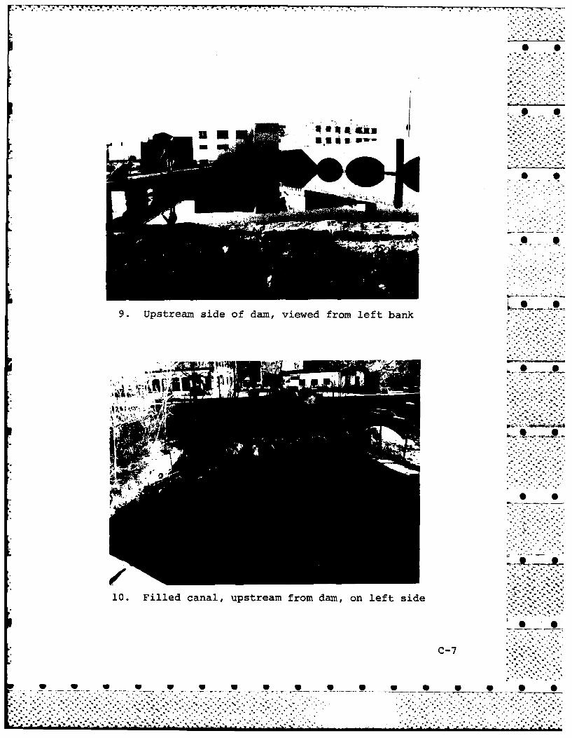
The upstream end of an old canal is visible near the -orth end of Moody Street Bridge, Photo No. 10. The canalas been filled in with rocks, earth and a-concrete wall toheight of about 3 in. above the adjacent original stoneasonry walls. _.-.____.-.
d. Reservoir Area. The area along the Charles RiverLpstream from the Moody Street Dam is highly developed " '.Lnd has low relief, Photos No. 1 and 9. There appears toie no probability that landslides into the river would causeraves which would overtop the dam. *No conditions whichtight result in a sudden increase in sediment load into the 0 0'iver were noted.
e. Downstream Channel. The Charles River flows in areneral easterly direction from the Moody Street Dam to the,iver's mouth at Boston Inner Harbor. The Bleachery Dam,rhich is located about 0.8 miles downstream from the Moody S S;treet Dam, has a crest elevation of 20.6 ft. The Water-:own Dam is located about 2.8 miles downstream from theloody Street Dam and has a crest elevation of 8.6 ft.
There are industrial, residential, commercial and re-:reational developments on both banks of the river. Two - 9 .;ailroads and road crossing exist over the river between.he Moody Street Dam and the Bleachery Dam. The MDC is:urrently involved in an improvements program in thisLrea which includes removal of some buildings located in -he river's flood plain and adding new operational'acilities such as a fish ladder and quick release flash-oard mechanisms to the dam.
The channel is about 80 ft. wide and about 12 ft. deepLt a distance of about 150 ft. from the Moody Street Dam'he channel width increases to about 120 ft. at a sectionLbout 300 ft. downstream of the existing Waltham gaging •Itation, or about 1,100 ft. from the dam.
There is a new reinforced concrete training wall on:he left side of the channel extending downstream from:he fishway and both banks are lined with riprap. Photoslo. 11 and 12 show the condition of the downstream channel.
1.2 Evaluation
Based on the examination of 6 December 1978, visible>ortions of the dam appear to be in good condition. However,mother examination should be made at a time when there is.ow flow to observe the condition of the granite masonryipillway weir, the downstream apron and individual flashboards.
10*-------------..:.:..:....-
.....................................................................
...-. .... . .. >.-..- .......... .- ..-.. - ..--.. '.. .•.. ....--. --.- ,

SECTION 3 - VISUAL EXAMINATION
3.1 Findings
a. General. The Phase I visual examination of theMoody Street Dam was conducted on 6 December 1978. c'.--.-
The visible portions of the dam appear to be in good -condition. However, water flowing over the spillway weir 0 0prevented a complete visual examination. For that reason,and because there is no apparent means of lowering thewater level below the spillway crest, the overall condition .. ....-.of the dam can only be considered fair at this time.
A visual inspection check list is included in Appendix 6 . -A and selected photographs of the project are given inAppendix C. A "Site Plan Sketch", page C-1, shows thedirection of view for each photograph.
b. Dam. The spillway weir is constructed on granite .masonry aniis apparently founded on glacial till. Acomplete examination of the weir was not possible due toflow of water, Photos No. 1, 2, 3 and 4. The downstreamapron was not visible. There is apparently no means to '- - --lower the water level below the spillway crest.
There was no indication of settlement or instabilityof the fill at the left abutment; no evidence of seepagewas observed either in the low area beyond the abutmentor in the lower floor of the adjacent old mill building.
c. Appurtenant Structures. A foot bridge is mounted Pon,along the crest of the spillway, with provision for 28bays of flashboards. Thirteen bays had 2 flashboards and15 bays had 3 flashboards in place. The foot bridge wasin good condition, Photo No. 3. The condition of theindividual flashboards was obscured by flow of water.. - -
The quick release mechanism for the flashboards (described .
in Section 1.3j) was not demonstrated.
The condition of masonry training walls was good,Photos No. 5, 6 and 8. Some minor staining and spallingwas noted.
A new reinforced concrete fishway structure at theleft end of the spillway was near completion, Photos No.1 and 7. The condition of the fishway was excellent. "" "
9
......... -1..°.." ". a .
. . . . . . . . .. . . . . . . . . . . . . . . . . . . . . . .' .
. . . . . . . . . . . . . . . . . . . . . . . .. °

.. .-* -_ ., - .* ..... - . - . .- . o-. - --_. .*. . - _ . . . - . - .- . .. , , . , °
SECTION 2 - ENGINEERING DATA
2.1 Design Data
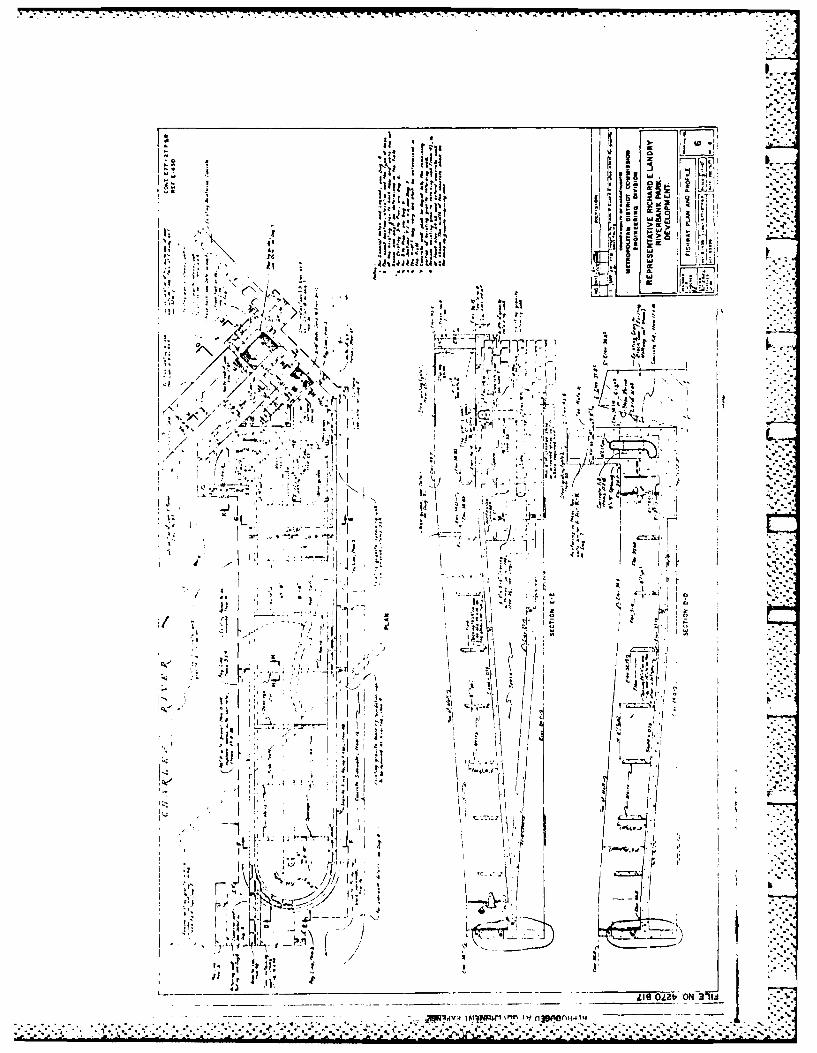
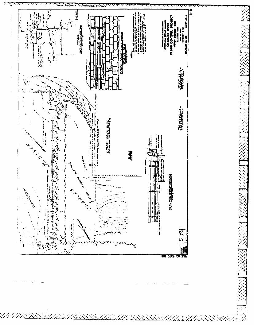
No design data for the original dam were located and 0 Onone are believed to exist. Some details of the dam areshown on MDC Contract No. 253 drawings for the "CharlesRiver Flood Control Project", dated 2 November 1959.Design details including boring logs for the fishwaystructure are included in MDC Contract No. E77-27 P&Rdrawings for the "Representative Richard E. Landry River- • *bank Park Development", dated 15 December 1977. Selectedsheets from these two sets of drawings are included inAppendix B.
2.2 Construction Data• . 0
No records of the construction of the original damwere located and none are believed to exist. Constructionphotos of the fishway are available at the MDC.
2.3 Operational Data
There were no operational records disclosed for theMoody Street Dam. The dam is part of the Charles RiverBasin system which is monitored at gaging stationslocated on the Charles River at Charles River Village,Mother Brook at Dedham and downstream of Moody Street Damin Waltham.
2.4 Evaluation of Data
a. Availability. A list of engineering data avail-able for use in preparing this report is shown on pageB-1. Selected documents from the list are also includedin Appendix B.
b. Adequacy. There was a lack of engineering dataavailable to aid in the evaluation of Moody Street Dam.This Phase I assessment was therefore based primarily onvisual examination, approximate hydraulic and hydrologiccomputations, consideration of past performance andapplication of engineering judgement.
c. Validity. There is no reason to doubt the validity . -..of availabe data.
, ..- . • .. ° . - -
8
o-... . . . . . . .
. -7 .-..-n -. j--.-' -~~~~~~~.. ...... ... ..... °.. ..... . .......... • . ....... ... ., .
• ,....-...-.-. , - -- .. ,.. . -... *.. .. :%". .•. . .. . - .. , -. ... ° ... .-. . ,- - '.. - -

W7,....
6. D/S channel .............. Concrete and graniteblock apron extends50 ft. downstream.Channel about 80 ft.wide and 12 ft. deepabout 150 ft. down-stream
j. Regulating Outlets. There are no regulating gatesfor the facllity. The upstream water level is regulatedby the addition of flashboards at the spillway. The crestof the spillway without flashboards is approximately El.32.2. The use of the maximum amount of flashboards wouldraise the crest to approximately El. 35.0. The length of
* crest capable of receiving flashboards is approximately169 feet.
In times of emergency, the flashboards could be quickly* released by pushing down individual vertical steel arms
located on the upstream side of the walkway, Photo No. 9.This, in turn, would push down the horizontal levers underthe walkway, Photos No. 3 and 4, releasing the verticalflashboard stanchions to which they were hooked. Every ...second stanchion is equipped with this quick releasemechanism, Photo No. 5, thereby releasing two bays offlashboards each and lowering the crest height to El. 32.2.
The fishway has a channel inlet 5 ft. wide by 7 ft.high with invert El. 30.5.
_ .°- '.. -'.°,..
7
*2 . .:, . .
. . . . . . . . . .. . . . . . . . . . . . . . . . . . . . . . . . . . . . . .
. . . . . . . . . . . . . . . . . . . . . . . . . .,. . . . . . . . . . . . . . . . . . . . .

e. Storage (acre-feet)
1. Recreation pool .......... 2,100 (top of flashboards)2. Flood control pool ....... Not applicable3. Spillway crest ........... 1,450 W4. Top of dam (left
training wall) ......... 2,9505. Test flood pool .......... 4,600
f. Reservoir Surface (acres)
1. Recreation pool .......... 2502. Flood control pool ....... Not applicable3. Spillway crest ........... 2054. Test flood pool .......... 5605. Topof dam.............. 335
g. Dam
1. Type......................Granite masonry with-overflow spillway
2. Length ................ 169 ft. -, =
3. Height (top left train- ping wall to channeldownstream of apron) ... 22 ft. (approx.)
4. Top width of weir ........ 6.25 ft.5. Side slopes .............. Not applicable6. Zoning ................... Not applicable "7. Impervious core .......... Not applicable 1.....*8. Cutoff ................... Unknown9. Grout curtain ............ Unknown
10. Other ................... Top of spillway weirapprox.- 7.5 ft. abovetop of apron
h. Diversion and Regulating Tunnel. Not applicable
i. Spillway
1. Type ..................... Overflow, granitemasonry, gravity type 0
2. Length of weir ........... 169 ft.3. Crest elevation .......... 32.24. Gates .................... None (flashboards are
a maximum of 2.8 ft.in height) a
5. U/S channel .............. Moody Street Bridgewith 9 arched openingsabout 100 ft. upstream
6
.. . . .. . . . . . . . . ... ..
""-"~~~~~~~~~~~~~~~ ".. -".. - ' " .-"- " " "" " "- "".-" ' -" .-' ' '- ".-' .- ".' ". -."" - -.- .'" .5" " .' .".' - - "'" -L '
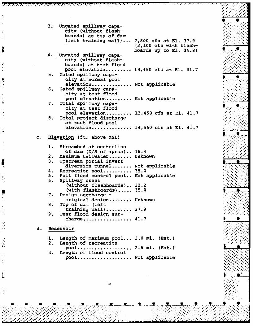
3. Ungated spillway capa-city (without f lash-boards) at top of dam(left training wall)•... 7,800 cfs at El. 37.9
9 (3,100 cfs with flash-.boards up to El. 34.8)
4. Ungated spillway capa-city (without flash-boards) at test floodpool elevation ......... 13,450 cfs at El. 41.7
5. Gated spillway capa-city at normal pool
lelevation ............. Not applicable ..-
6. Gated spillway capa-city at test floodpool elevation ......... Not applicable
7. Total spillway capa-city at test floodpool elevation ......... 13,450 cfs at El. 41.7
8. Total project dischargeat test flood poolelevation .............. 14,560 cfs at El. 41.7
c. Elevation (ft. above MSL)
1. Streambed at centerlineof dam (D/S of apron).. 16.4
2. Maximum tailwater........ Unknown3. Upstream portal invert
diversion tunnel ....... Not applicable4. Recreation pool .......... 35.05. Full flood control pool.. Not applicable6. Spillway crest
(without flashboards),, 32.2(with flashboards) ..... 35.0
7. Design surcharge -
original design ........ Unknown8. Top of dam (left
training wall) ......... 37.99. Test flood design sur-
charge ................. 41.7
d. Reservoir
1. Length of maximum pool... 3.0 mi. (Est.)2. Length of recreation
pool ................... 2.6 mi. (Est.)3. Length of flood control
pool ................... Not applicable
5
V V * * *. *, V *•. ."
.... .-.'.-...'.-.'.-...... . ...+.. ....... ... .",. . .. . . . . . . .-"" ".".,. "
aj - - .-. % % % ? "% - % .' " ' - . - : ..A ." -N ". 7"6 ' • , " J "
-7 T
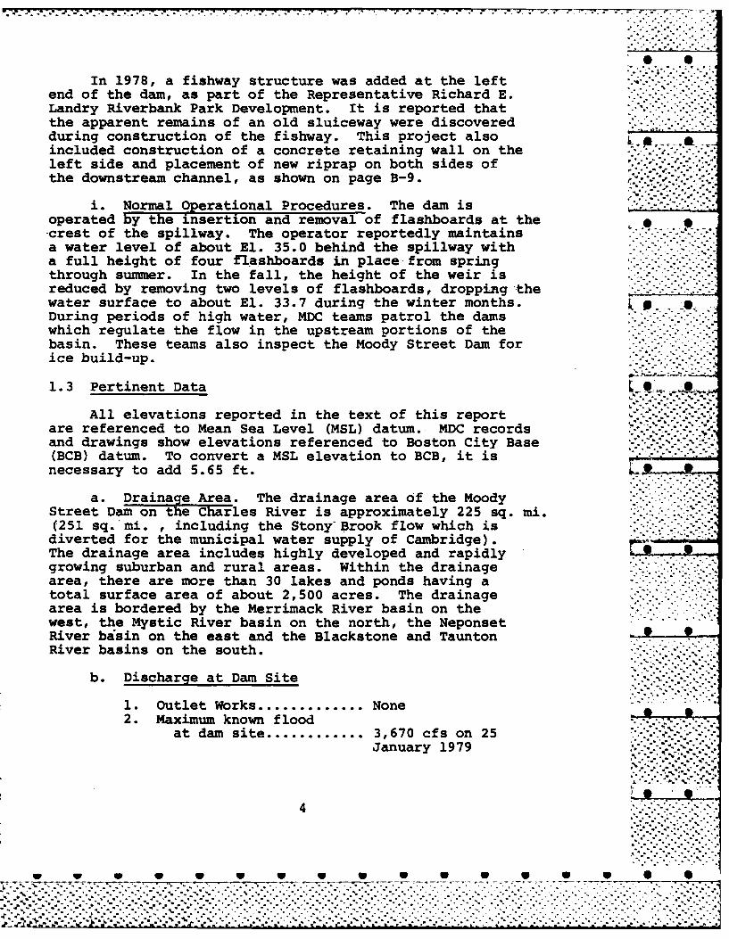
In 1978, a fishway structure was added at the leftend of the dam, as part of the Representative Richard E.Landry Riverbank Park Development. It is reported thatthe apparent remains of an old sluiceway were discoveredduring construction of the fishway. This project also -. .included construction of a concrete retaining wall on theleft side and placement of new riprap on both sides of 'the downstream channel, as shown on page B-9. " -- ""
i. Normal Operational Procedures. The dam is "__"_""'"-operated by the insertion and removal of flashboards at the-crest of the spillway. The operator reportedly maintainsa water level of about El. 35.0 behind the spillway witha full height of four flashboards in place from springthrough summer. In the fall, the height of the weir isreduced by removing two levels of flashboards, dropping thewater surface to about El. 33.7 during the winter months. , .During periods of high water, MDC teams patrol the damswhich regulate the flow in the upstream portions of thebasin. These teams also inspect the Moody Street Dam forice build-up.
1.3 Pertinent Data L ..-.+ ~.. - * - .-."-.-
All elevations reported in the text of this reportare referenced to Mean Sea Level (MSL) datum. MDC recordsand drawings show elevations referenced to Boston City Base(BCB) datum. To convert a MSL elevation to BCB, it isnecessary to add 5.65 ft.
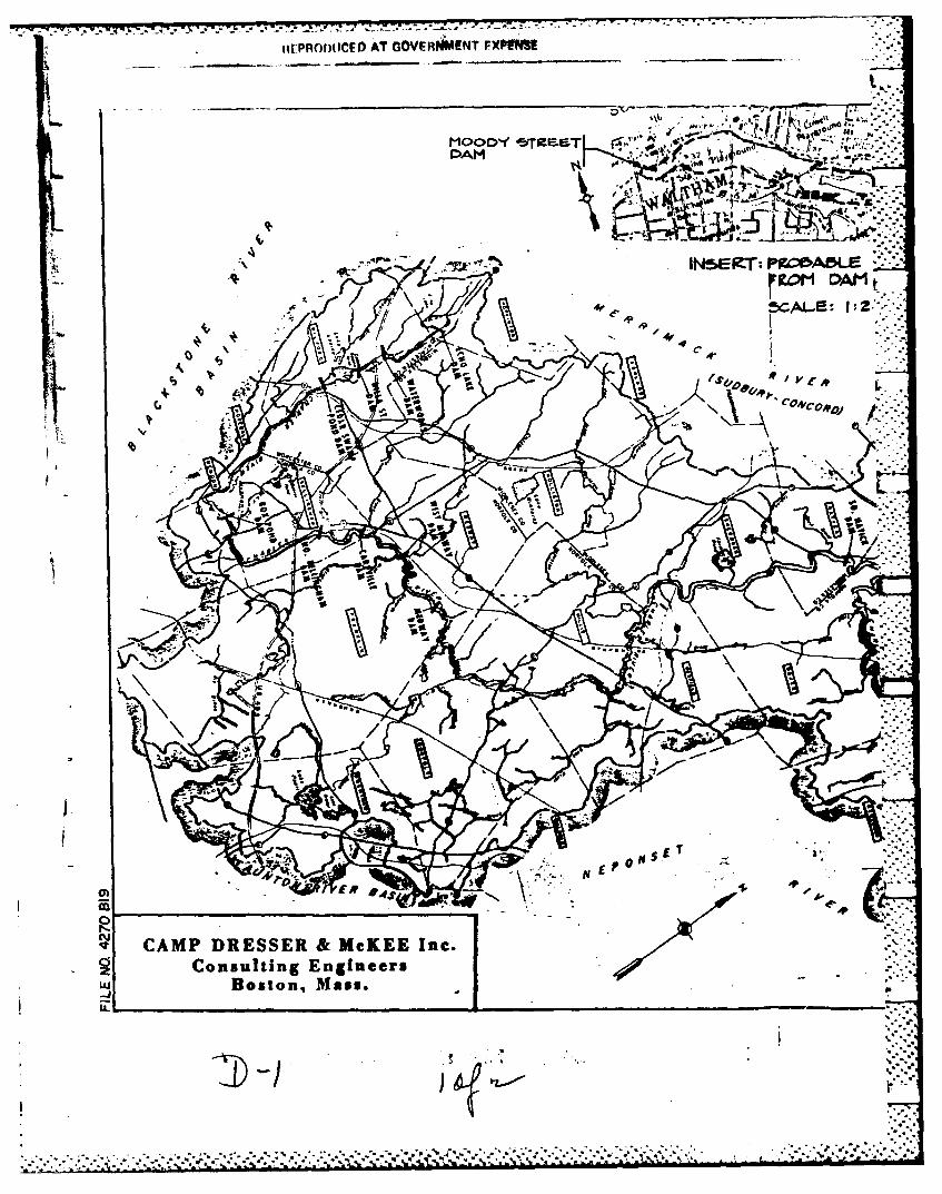
a. Drainage Area. The drainage area of the MoodyStreet Dam on the Charles River is approximately 225 sq. mi.(251 sq. mi. , including the Stony" Brook flow which isdiverted for the municipal water supply of Cambridge).The drainage area includes highly developed and rapidlygrowing suburban and rural areas. Within the drainagearea, there are more than 30 lakes and ponds having atotal surface area of about 2,500 acres. The drainagearea is bordered by the Merrimack River basin on thewest, the Mystic River basin on the north, the NeponsetRiver basin on the east and the Blackstone and TauntonRiver basins on the south.
b. Discharge at Dam Site
1. Outlet Works ............. None2. Maximum known flood
at dam site ............ 3,670 cfs on 25January 1979
4
W W W W V W W W V V V V
* -°
-,. .% % ."
.7 7-77- '--
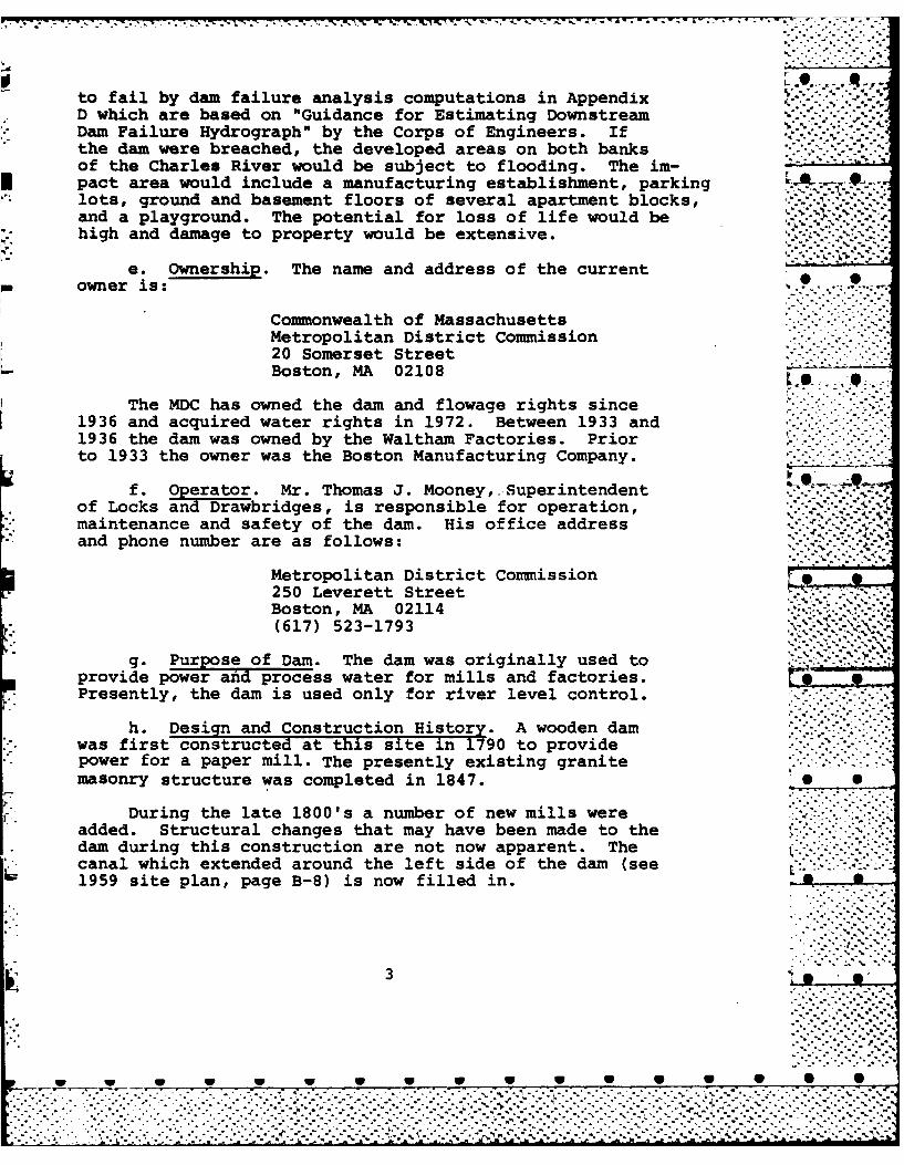
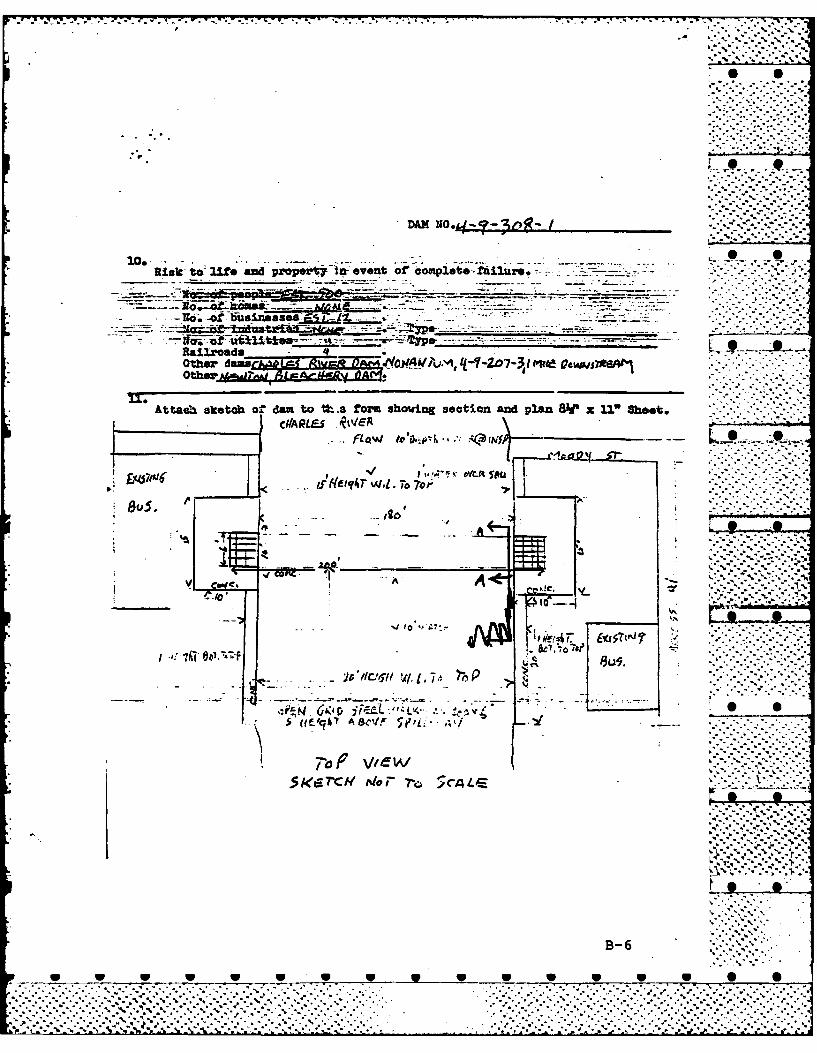
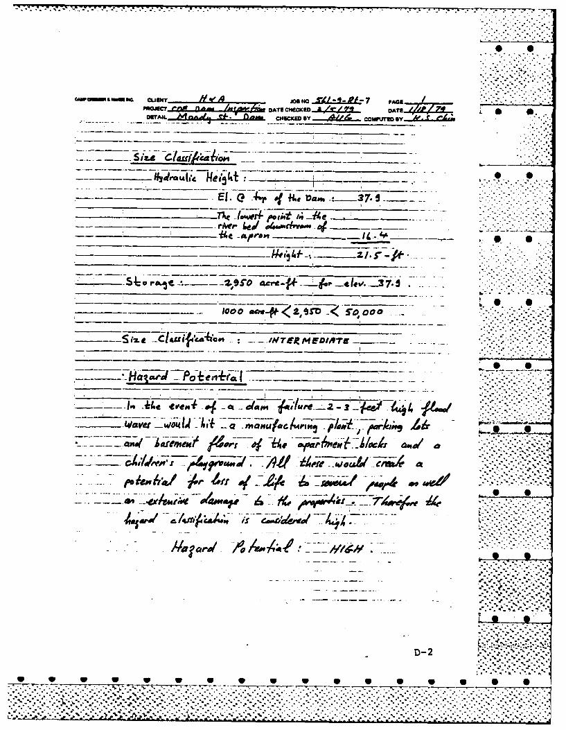
to fail by dam failure analysis computations in Appendix ... .. ,D which are based on "Guidance for Estimating DownstreamDam Failure Hydrograph" by the Corps of Engineers. If .- -the dam were breached, the developed areas on both banksof the Charles River would be subject to flooding. The im-pact area would include a manufacturing establishment, parkinglots, ground and basement floors of several apartment blocks, -and a playground. The potential for loss of life would behigh and damage to property would be extensive. .":-"..
e. Ownership. The name and address of the currentowner is:
Commonwealth of MassachusettsMetropolitan District Commission20 Somerset StreetBoston, MA 02108
The MDC has owned the dam and flowage rights since1936 and acquired water rights in 1972. Between 1933 and1936 the dam was owned by the Waltham Factories. Priorto 1933 the owner was the Boston Manufacturing Company.
f. Operator. Mr. Thomas J. Mooney,. Superintendentof Locks and Drawbridges, is responsible for operation,maintenance and safety of the dam. His office addressand phone number are as follows: ..... °..
Metropolitan District Commission250 Leverett StreetBoston, MA 02114(617) 523-1793
g. Purpose of Dam. The dam was originally used toprovide power and process water for mills and factories.Presently, the dam is used only for river level control. i.. .
h. Design and Construction History. A wooden damwas first constructed at this site in 1790 to providepower for a paper mill. The presently existing granitemasonry structure was completed in 1847.
During the late 1800's a number of new mills wereadded. Structural changes that may have been made to thedam during this construction are not now apparent. Thecanal which extended around the left side of the dam (see1959 site plan, page B-8) is now filled in.
4 .oO- ° -. -*
b2 3
____ W W V W- V W*-
-*0%-
..
. .. ..... .... .... .... ..... .... .... .......... ...... ..... ...... ..... ...... .....
. .. -. . . .. . . . . . . . . . . . . . .4 . . .% -. -. - . . % .; . " °
.•. " . % o.; . . , - % °.

1.2 Project Description
a. Location. Moody Street Dam is located on theCharles Riverjust downstream from the Moody Street Bridge,
* in Waltham, MA, as shown on the Location Map, page vii.
b. Dam and Appurtenances. The Moody Street Dam con-sists of a granite masonry structure with a full-lengthoverflow spillway, a downstream apron and a fishway -.structure. The "Site Plan Sketch", page C-i, shows thegeneral layout of the dam and appurtenanances. More de-
*- tailed drawings are included in Appendix B.
The spillway weir is an overflow gravity type structure* having a total length of approximately 169 ft. and a height- of about 7.5 ft. measured from the top of the apron. A
typical section of the upper part of the weir is shown on P-_ page B-8. Up to 4 levels (about 2.8 ft.) of flashboards which
can be quickly released are mounted beneath an access walkwaywhich extends along the length of the weir. The concrete andgranite block apron extends about 50 ft. downstream.
A reinforced concrete fishway structure is locatedat the left end of the spillway and forms the downstreamportion of the left training wall. Page B-10 shows aplan and profile of the fishway. The upstream portion ofthe left training wall and the right training wall areformed by vertical granite block retaining walls. TheI right abutment is close to the lower floor of a commercialbuilding while the ground surface beyond the left trainingwall drops down several feet to an access drive and an oldmill building.
The upstream end of a canal, which once carried water* to factories located to the left of the dam, can be seen near
the north end of Moody Street Bridge. This old canal andthe sluiceways under the buildings are now filled in.
c. Size Classification. The storage to the top of* Moody Street Dam is estimated to be 2,950 acre-ft., and
the corresponding maximum height of the dam measured fromthe top of the left training wall to the stream channel justdownstream of the apron is approximately 22 ft. Storage of """from 1,000 to 50,000 acre-ft. and/or a height of from 40to 100 ft. places a dam in the "intermediate" size category,according to the guidelines established by the Corps ofEngineers.
d. Hazard Classification. This dam is confirmedas having a "high" hazard potential in the event it were
2 '
w~~~~~~4 0.
. ,..'...'.....'..'........'...'..'.-.'........ "..'..................................-.....-..,........, -o,........ ...... °..............,.....,........-...,, ..-. .........-- .. ..% . ".. . . .... .... -... '.#........................
PHASE I INVESTIGATION REPORTNATIONAL DAM INSPECTION PROGRAM
U MOODY STREET DAMMA 00345
.- '% •"..
- .- ** % -
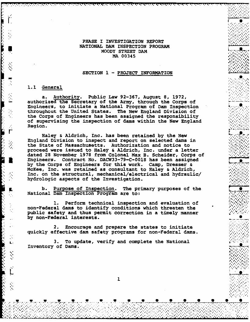
SECTION 1 PROJECT INFORMATION
1.1 General
a. Auhriy Public Law 92-367, August 8, 1972,- authorized he Secretary of the Army, through the Corps of
Engineers, to initiate a National Program of Dam Inspectionthroughout the United States. The New England Division ofthe Corps of Engineers has been assigned the responsibilityof supervising the inspection of dams within the New EnglandRegion.
Haley & Aldrich, Inc. has been retained by the New* *~. England Division to inspect and report on selected dams in
the State of Massachusetts. Authorization and notice to*proceed were issued to Haley & Aldrich, Inc. under a letter
. dated 28 November 1978 from Colonel Max B. Scheider, Corps ofEngineers. contract No. DACW33-79-C-0018 has been assignedby the Corps of Engineers for this work. Camp, Dresser&
SaMcKee, Inc. was retained as consultant to Haley & Aldrich,Inc. on the structural, mechanical/electrical and hydraulic/hydrologic aspects of the investigation.
Ld b. Purpose of Inspection. The primary purposes of theSNational Dam Inspection Program are to:
1. Perform technical inspection and evaluation of '~*'~
non-Federal dams to identify conditions which threaten thepublic safety and thus permit correction in a timely mannerby non-Federal interests.
2. Encourage and prepare the states to initiatequickly effective dam safety programs for non-Federal dams.
L-"3. To update, verify and complete the NationalInventory of Dams.
-... no-Feealdmst ie.fy...ton....t..tn h ..."-..."'pubicsaftyandths prmt .c.r.tin.n.atie. ymaner..'-....-.'.
"... ,......'..
_ . .% .. .° .

16i~
~' : ~':'No
J.~ ~ /--
*N(~J1
*~ _____ Cul ~ i ueO o Ir
DAM SIT
*00i
II-
vtil
. . . . . . .r
DA:.Xq~ . tret.. ..................................

F 7 -. S
ovrve ofMoySre a
vip
W W W
..p .
- ~%. -• 7..-*7-"
F S
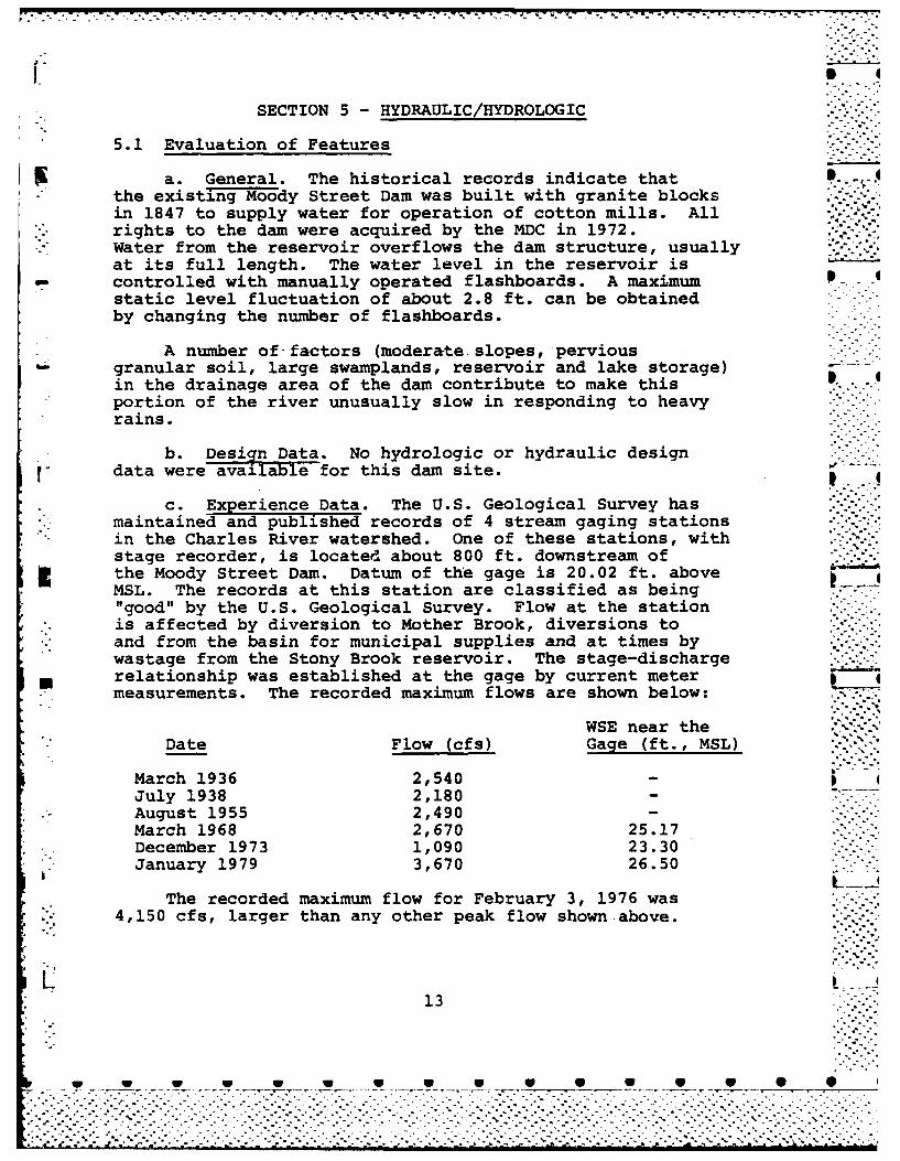
SECTION 5 - HYDRAULIC/HYDROLOGIC
5.1 Evaluation of Features
a. General. The historical records indicate that .the existing Moody Street Dam was built with granite blocksin 1847 to supply water for operation of cotton mills. All :....rights to the dam were acquired by the MDC in 1972.Water from the reservoir overflows the dam structure, usuallyat its full length. The water level in the reservoir is
- controlled with manually operated flashboards. A maximum P .-static level fluctuation of about 2.8 ft. can be obtainedby changing the number of flashboards.
A number of- factors (moderate. slopes, perviousgranular soil, large swamplands, reservoir and lake storage)in the drainage area of the dam contribute to make thisportion of the river unusually slow in responding to heavyrains.
b. Design Data. No hydrologic or hydraulic designr data were available for this dam site.
c. Experience Data. The U.S. Geological Survey has* maintained and published records of 4 stream gaging stations
in the Charles River watershed. One of these stations, withstage recorder, is located about 800 ft. downstream ofthe Moody Street Dam. Datum of the gage is 20.02 ft. aboveMSL. The records at this station are classified as being"good" by the U.S. Geological Survey. Flow at the station
. is affected by diversion to Mother Brook, diversions to
. and from the basin for municipal supplies and at times bywastage from the Stony Brook reservoir. The stage-discharge
M relationship was established at the gage by current metern*. measurements. The recorded maximum flows are shown below:...-
WSE near theDate Flow (cfs) Gage (ft., MSL)
March 1936 2,540July 1938 2,180
. August 1955 2,490March 1968 2,670 25.17
* December 1973 1,090 23.30January 1979 3,670 26.50
The recorded maximum flow for February 3, 1976 was"' 4,150 cfs, larger than any other peak flow shown above.
13
[ ... . . . . . . . . . . . . . . . . . . . .

1.~~~ 7 7 14 7
However, it was caused artifically by the blasting of iceblocks jammed at the crest of the dam.
d. Visual Observations. About 100 ft. upstream of thedam is the Moody Street bridge, a concrete structure withnine arched openings. During the day of the field inspectionwater was overflowing the dam; out of 28 flashboard bays13 had two and 15 had three boards in place. The upstreamwater level at the time of the site visit was estimated
* " to be about El. 34.5.
A manufacturing building on the left downstream bankhas been removed. Construction of a fish ladder and aconcrete retaining wall in this area were at a stage close j *to completion. The old outlets to the mill building have
- been backfilled. Both banks of the river downstream of the- dam are protected by riprap.
e. Test Flood Analysis. Based upon the Corps ofr Engineers guidelines, the recommended test flood for the
size (intermediate) and the hazard potential (high) isthe Probable Maximum Flood (PMF). The peak flow rateof 65 cfs/sq. mi. has been determined specifically forthe Charles River basin as a result of hydrologic studiescompleted by the Corps of Engineers. The resulting PMFinflow for the 225 sq. mi. drainage area (excludingStony Brook Basin) is about 14,800 cfs.
Surcharge-storage routing was performed through the. reservoir assuming no flashboards at the crest of the dam.
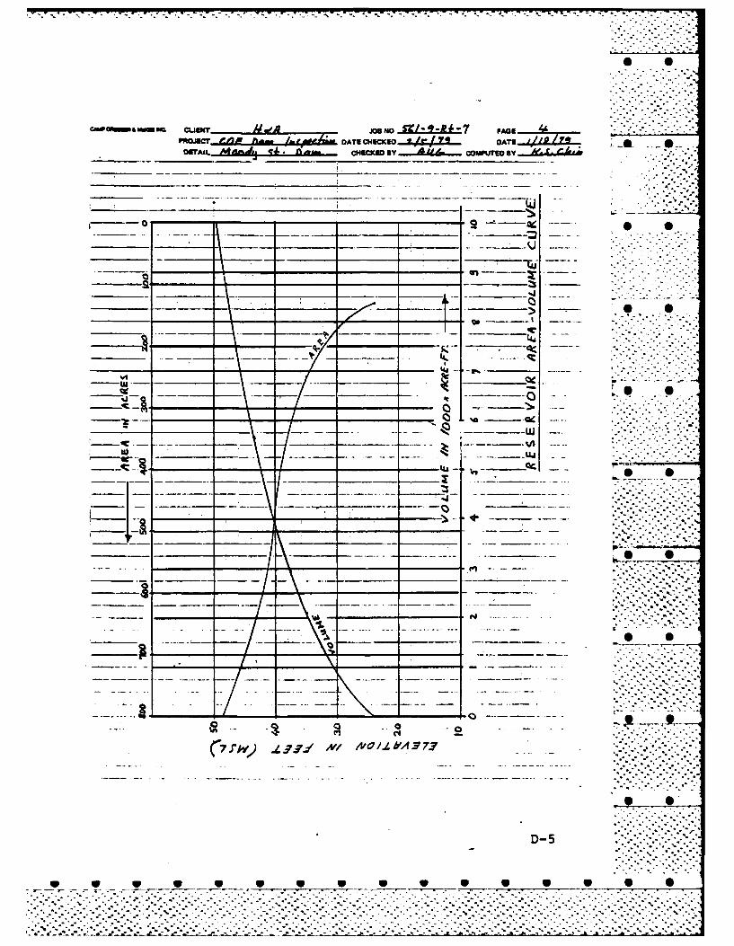
The water surface in the reservoir during the test flood wasestimated to be at El. 41.7, about 3.8 ft. above .heleft training wall. The test flood outflow was determinedto be 14,560 cfs, which indicates no substantial reductionof flow through the reservoir surcharge-storage. Thespillway stage-discharge and the reservoir area-volumecurves, which were used in the analysis, are shown inAppendix D. In conclusion, the spillway itself would not S
* be able to pass the test flood without flooding bothS". banks and the shorelands along the reservoir.
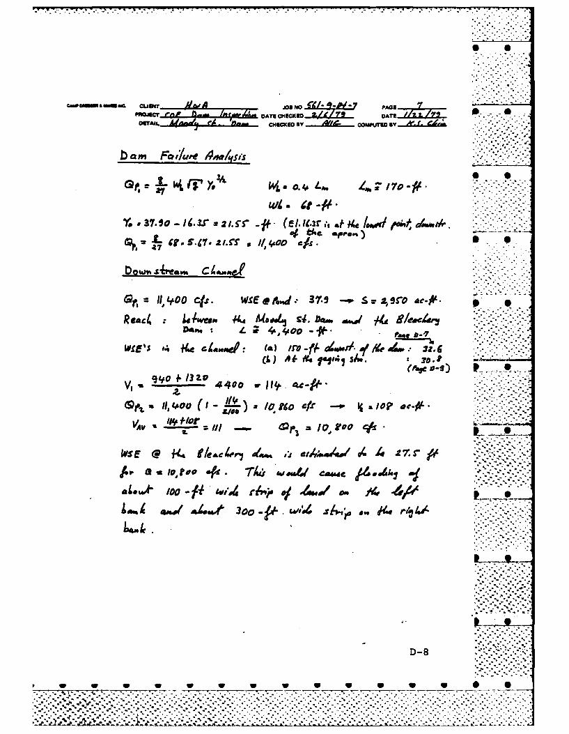
f. Dam Failure Analysis. Based on Corps of Engineers-. Guidelines for Estimating Dam Failure Hydrographs and
assuming that 40 percent of the 169 ft. long weir wouldfail, the peak failure outflow is estimated to be 11,400
* cfs. A "reach" between the Moody Street Dam and the
14- -.- , °--'. -
. . . . . . . . . * * ° . . . . . *.. ~ . . .- - .- -. . . .- °. .,
. . .. . .,
dW6A°b
Bleachery Dam was studied for flood routing.
Storage volume of the reach is estimated to be about110 acre-feet which would reduce the peak failure floodflow to about 10,800 cfs. The related water surface .- -q -elevations are estimated to be El. 32.2 near the MoodyStreet Dam, El. 30.8 ft. at a distance of about 1,100 ft.from the dam and El. 27.5 ft. at the Bleachery Dam. Thishydraulic profile would result in flooding of an extensivearea on both banks of the river. Several buildings withparking lots, manufacturing plants and a playground would 0 0be affected. Due to the potential loss of life and ex-tensive property damage that would result from a failureof the dam, the hazard classification is considered high.
.- . . . .. .. .dS
~-
- , -.°.- "-T-•
- _ .. ' .".p'
- . . . . . .. . .- -,...-.. , . -...- ,-.-. .: .'.. .
. . . . . . . . . . . . . . . . . . . . . . .. . . . . . . . . . . . . .-...-. ,
S.. a •
-.. o-.. . . .=
SECTION 6 - STRUCTURAL STABILITY
6.1 Evaluation of Structural Stability
a. Visual Observations. The spillway weir and apronwere obscured by flowing water; however, no evidence of . -. -;settlement, lateral movement or other signs of structural .. '.-.-;instability was noted. Masonry training walls appeared tobe stable.
b. Design and Construction Data. There are no designor construction records to aid in the evaluation ofstructural stability of the dam. However, the dam hasapparently performed satisfactorily for over a hundred years.
c. Operating Records. No operating records areavailable to aid the evaluation of structural stability.
d. Post-Construction Changes. Other than for theaddition of the fishway, and the walkway and flashboardreconstruction shown on the 1959 plans, there are no Orecords of any changes that may have been made to theoriginal dam.
e. Seismic Stability. Moody Street Dam is locatedin a Seismic Zone 3. Pertinent data needed for atheoretical analysis of seismic stability are unavailable.Therefore, the seismic stability of the dam is unknown. .-- '.-K..
7t
C.° . - .. o
16
..............................-.-.- C.. **. °. ...........W~~~_ ... _0 W
. .- ' .° .. .. -. .° .. . . . . . . . . . . . . . . . . . . . . .. . . . . . . . . . . . . ..-.-
. . . . . . . . . . . . . . . . . . . . . .. ,......... . . . . . . .

7 V.
SECTION 7- ASSESSMENT, RECOMMENDATIONSAND REMEDIAL MEASURES
7.1 Dam Assessment
a. Condition. The visual examination of Moody StreetDam indicates that the visible portion of the structure areapparently in good condition. However, flowing water pre-vented a complete examination. There is also no means to ..- * ilower the water level below the spillway crest. For thesereasons, the overall project condition can only be considered . 0
fair at this time.
Based on the results of computations included inAppendix D and described in Section 5, the spillway is notcapable of passing the test flood, which for this structureis the PMF. The PMF outflow of 14,560 cfs (65 csm) would .
-. overtop the dam (left training wall) by about 3.8 ft. Withthe water level at the top of the left training wall, thespillway (without flashboards) can pass 7,800 cfs which is54 percent of the test flood.
b. Adequacy of Information. This evaluation of thedam is based primarily on visual examination, approximatehydraulic and hydrologic computations, consideration ofpast performance and application of engineering judgement.Generally the information available or obtained was adequatefor the purposes of a Phase I assessment. However,p additional information on the condition of the spillway weirand apron should be obtained as outlined in Section 7.2.
c. Urgency. The recommendations for additional in-vestigations and remedial measures outlined in Section 7.2and 7.3, respectively, should be undertaken by the Owner .
m and completed within one year after receipt of this report.
d. Need for Additional Investigation. Additionalinvestigations should be performed by the Owner as out- ..* .
lined in Section 7.2.
7.2 Recommendations 0
It is recommended that the Metropolitan DistrictCommission, owner of the dam, assign or engage a registeredprofessional engineer to undertake the following investi-gations:
1. Investigate possible measures to provide ameans of lowering the water level below the
17
___ w ___'_W... -7 , , , .
_w w - -. U. * * -_ _ .. :--B B
spillway crest. Consideration should also begiven to increasing the capacity of the spillway.
2. Examine the dam at a time when there is low flowto assess the condition of the granite masonryspillway weir, the downstream apron and theflashboards.
3. Assess the potential vulnerability of the damto seismic events by conventional equivalentstatic load methods.
7.3 Remedial Measures
Although the visible portions of the dam are generallyin good condition, it is considered important that thefollowing items be accomplished.
a. Operation and Maintenance Procedures. The Owner --
should prepare an operation and maintenance manual for .-.-. . . .the dam. The manual should include provisions for biennialtechnical inspection of the dam and for surveillance ofthe dam during periods of heavy precipitation and high priver water levels. The procedures should delineate theroutine operational procedures and maintenance work to be i*.'.*.done on the dam to ensure satisfactory operation and to - .-. -minimize deterioration of the facility-.
Because the dam is classified as having a "high" .hazard potential, the owner should also develop a writtenemergency preparedness plan and warning system to be usedin the event of impending failure of the dam. The planshould be developed in cooperation with local officialsand downstream inhabitants.
7.4 Alternatives
Not applicable.
18
-:.......................
. . o . - -..

APPENDIX A -INSPECTION CHECK LIST
Page
VISUAL INSPECTION PARTY ORGANIZATION A-i1
VISUAL INSPECTION CHECK LIST
Dam Embankment A-2
Outlet Works -Spillway Weir, Approach A-2and Discharge Channel
Outlet Works -Intake Channel and A-3Outlet Structure Intake
Outlet Works -Gate House A-3

-. . . .. . . . . . . . . . .-1-7 1 7'- - .. x *-
VISUAL INSPECTION PARTY ORGANIZATION
NATIONAL DAM INSPECTION PROGRAM
Dam: Moody Street
Date: 6 December 1978 ..
Time: 0800 to 1000
weather: Clear, cool (40 0 to 50 0 F)
Water Surface Elevation Upstream: 34.5 (MSL)
Stream Flow: Unknown
Inspection Party:
Peter L. LeCount -Soils/Geology
Richard A. BrownHaley & Aldrich, Inc.
A. Ulvi Gulbey -Hydraulic/Hydrologic SJoseph E. DowningRobert P. Howard -Structural/Mechanical
Camp, Dresser & McKee, Inc.
Present During Inspection:
John Gilmore, MDCRobert Carr, MDCNorman Saulnier, MDC
A-1
W w W _ S S
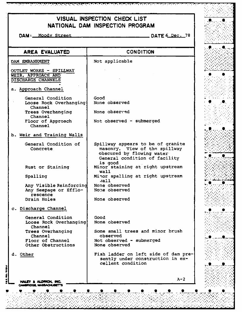
VISUAL INSPECTION CHECK LISTNATIONAL DAM INSPECTION PROGRAM
DAM: Moody Street DATE 6 Dec. 78
AREA EVALUATED CONDITION
DAM EMBANKMENT Not applicable
OUTLET WORKS - SPILLWAYWEIR, APPROACH AND 0 0DISCHARGE CHANNELS
a. Approach Channel
General Condition GoodLoose Rock Overhanging None observed .
ChannelTrees Overhanging None observe d
ChannelFloor of Approach Not observed - submerged
Channelil -. . - .. .,-,,-
b. Weir and Training Walls
General Condition of Spillway appears to be of graniteConcrete masonry. View of the spillway
obscured by flowing waterGeneral condition of facility .*is good
Rust or Staining Minor staining at right upstreamwall
Spalling Minor spalling at right upstream ",;all
Any Visible Reinforcing None observed -Any Seepage or Efflo- None observed
rescenceDrain Holes None observed
c. Discharge Channel
General Condition GoodLoose Rock Overhanging None observed
ChannelTrees Overhanging Some small trees and minor brush
Channel observedFloor of Channel Not observed - submergedOther Obstructions None observed
d. Other Fish ladder on left side of dam pre-sently under construction in ex-cellent condition .
................................- .. . . . . ,

VISUAL INSPECTION CHECK LIST mNATIONAL DAM INSPECTION PROGRAM
DAM: Moody Street DATE: 6 Dec. 78
AREA EVALUATED CONDITION
OUTLET WORKS - SERVICEBRIDGE
a. Superstructure
Bearings Not observedAnchor Bolts Not observedBridge Seat GoodLongitudinal Members Good pUnder Side of Deck Not applicableSecondary Bracing GoodDeck Grating in good conditionDrainage System Not applicableRailings GoodExpansion Joints None observed 0|.Paint Good
b. Abutment and Piers
General Condition of GoodConcrete t .
Alignment of Abutment GoodApproach to Bridge GoodCondition of Seat and Good
Backwal 1
OUTLET WORKS - GATEHOUSE Not applicable
° .,
WL MAR A ,aNCM M A-3CAMPO-.. ........-...-..
".'."-.'.,'"."....'............ . . ................... .....

* S
APPENDIX B - ENGINEERING DATA
Page
IST OF AVAILABLE DATA B-I
RIOR INSPECTION REPORTS
Date Description
22 March 1974 Mass. Dept. of Environmental B-2Quality Engineering
RAWINGS
Charles River Flood Control Project, Moody B-8treet Dam, Existing Dam", MDC Contract No.53, Sheet No. 2, 2 November 1959
Representative Richard E. Landry Riverbank B-9ark Development, Site Plan", MDC Contracto. E77-27 P&R, Drawing No. 3., 15 December977
Representative Richard E. Landry Riverbank B-10ark Development, Fishway Plan and Profile",DC Contract No. E77-27 P&R, Drawing No. 6, *5 December 1977
. .
* S
. ...• . . .
• • • • • • • • • • • • •
41 4) 4J 4-)
5.$14 w- .
W ~ C14 (12 C
o 4j 4 4 4
oo
0 m (
$4 3: U.P4 ~ ~ 9. 44M4)-I 0
01 &0 4) >1V l (O4) 4J 0I - - Jr
4) 4 Q *e0 C 0 V 1 -rAU IL) 444J4J -
4) 4) 0. .9 4)44)4r. -ra) -W.4) 3:-4. 4
4) a4 44) a) 00 0
4) 4 U)" $4~ 440W 044U00 4 41 V4) 2t 4 9
U)&) - 4))0)m. 0C)0a4) g 00> CO V 4) 4)9 M P
r-4 ) r-4 $4 ) r-40 4J '4 0 4) it4Ji0V04 00W 0 . aU am- M Cf4j M 4
"-4
w.4 z 4J04J0>1 zU
U 0 InC 4 5O $4) 4
04)- >Z" 4) 0 MI c ) 0)0 -4 m41toC4 -.i 1'4 In 0
"-44J 4) .4 U r-4 4Jr34 cfl. ~ . 4 - 0
4) 0 W 4"40 z)~~ .>i z 4*'4toz "4 >0 4
84 O>0 4J 4M 4) $4:rq *. 0%O -H Q) U r4 0 0 4J A
0) 0J 44 M 10 IM 4 J 4)
W ) ) Ek 4 W 0 W r4 W 4to0 . 4) ( W4)Oi1
.0 0OU > C~ 05. P M4a >.'~O U54 4) ) 00O 0h
30Z 041 (2 M . 13 Z4u
Er-1

S 0
iL;PEC!I01 REPOT flAAS AIND RESERVOIRS
(I.) Looatianz, lityP".. WALruAAA DA1I! 70. ~
Name of Dam MjQp4 ..STAET DAI~x Inspected byA. Z. PIZA z, N 0-* Daie-Fm. PARE
Das-ofInPection .2-2-77-t
-(2.) On~: r~z
.. Reg., -riada FaPrs.,. Contir'____________
isr,7J cgd--!-dzg~s 211 727-S2f-a 5 4 No.Stab TOl.fo.
2,Nale 3: ac NO. clty/Town State e I. o .
FQ -- City/-jTown btate Teal1 o .
~3)Caretaker: '1:7 any) e.g. superinl;,rn-,nt, plant mianager, a'p? oizxited by :. ..-
absentee o~inei , app intad by miz1tl w.ners.
S;. 111ji.ty/Town sts-a TeL,. I W
;TTupee Or f&.;d a(7i:- dama ihoUd rf3j. empletal-y)*1. 14n,'____2. Moderate_________
3. Sve 7 . Disastrous________
*This r-tiex m-.v cha:tge as lazid .,so 1,-%ngOe3 (futur6 ec;n
U~ 3 W 1 M-ZOAa-ZT aPTT A U_______C ~ fUA S . ALA46Y
B- 2
w lw w w w U UU U

-2 DA gk4o. 1-9-308-I
()Downstream Face of Dan: Condition: 1. Good k&' Minor Repairs -.
3. Major Repairs__ Urgnt Repr
comments:__________________________________
en9 i~z~ pnion-.. -,Good- 2. Minor Repair____
KStJor fea i
Commets: IwR& IS~ A10~S~t//~PI44Y
(1) Water level 0 Zime of in3PeCtinft bv , below .
top of d=. Principal spillwa-e4--
other_______
(111 Su~mmary of Deficiencies Notad:
Growth (Trees and Brush) on Zzbnlmeit_______________
Animal Burrows and Washout____________________
Damage to slopes or top of dnm____________________
Craked or Damaged Masonry______________________
3SrIdenoe o~f 3eepag3
Evidence of Piping___________________________
Leaks
Trcsah axdor debris impan,.in.3 flow_____________________
Cic~gsd or blocked spilw:17_______________________
Otlhor NoPEF;,CjAA/ciE NOTEO
B- 3
%

. .
PWOR, r*
4~J
-c-
0 w w w 9 9 a
4J
'41
144
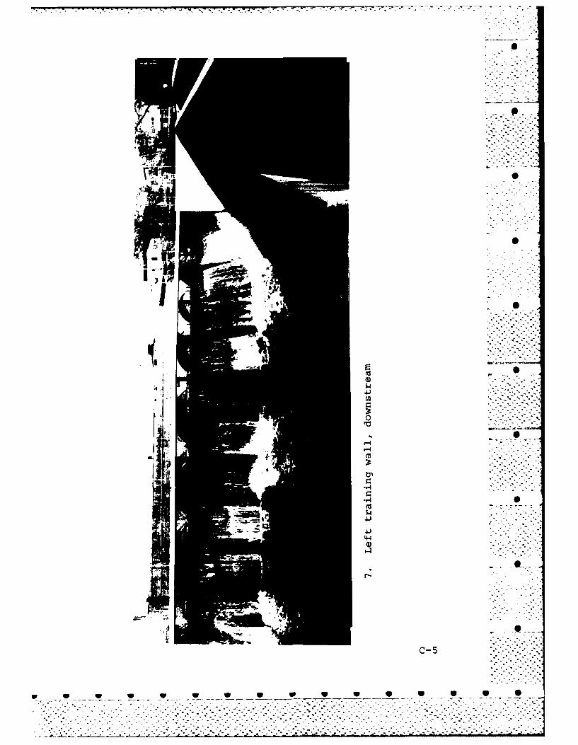
C- 5
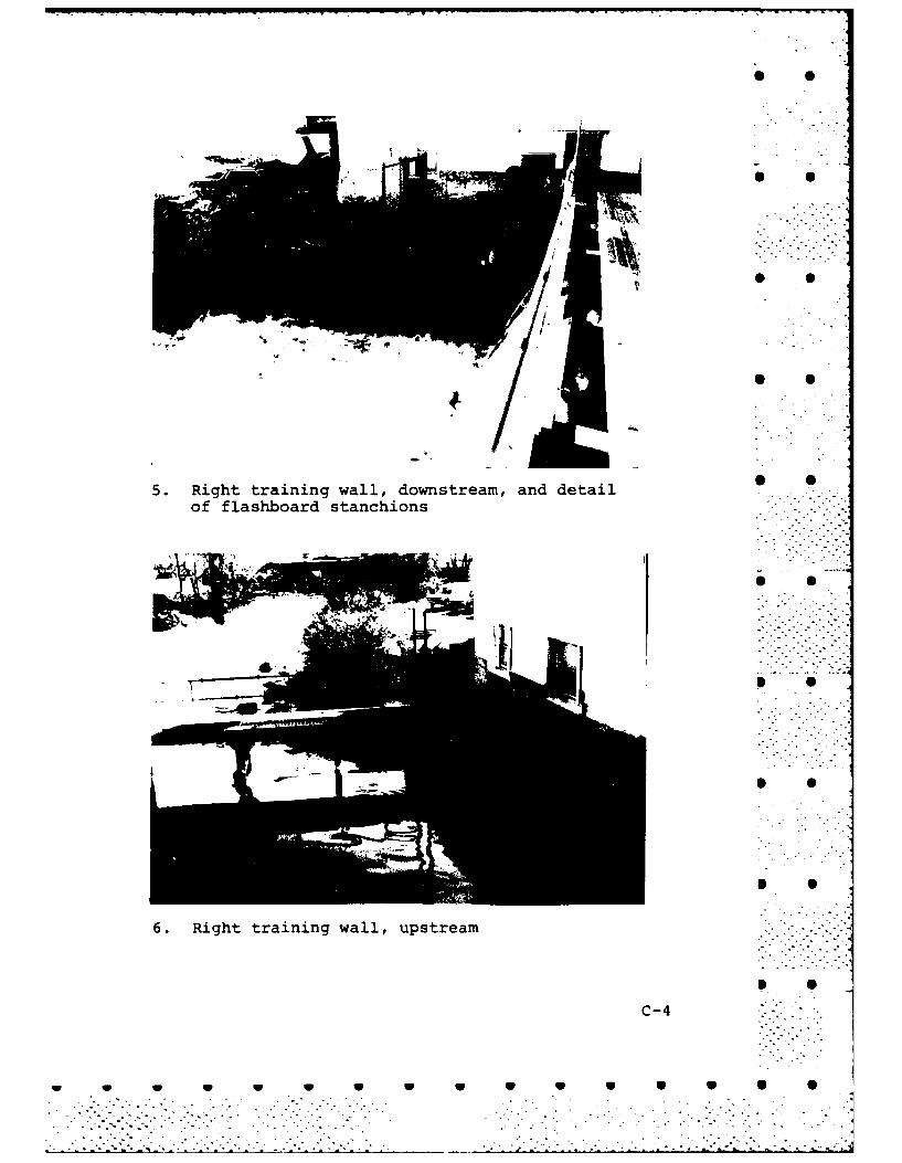
5. Right training wall, downstream, and detailof flashboard stanchions
6. Right training wall, upstream
C-4
W W W W W W 0 0 a 9 9
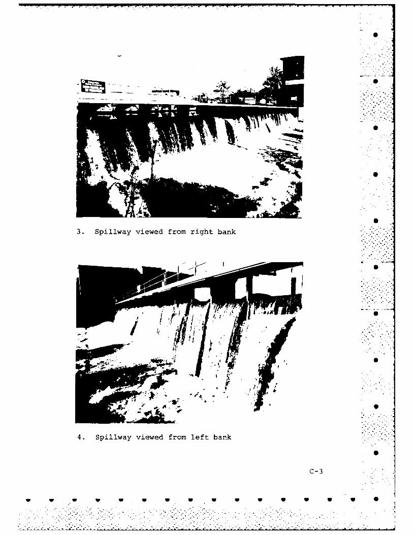
3. Spillway viewed from right bank
4. Spillway viewed from left bank
C-3
w w W V W W W V 0 a

-. -. -..........-. . -
- V.
* S
* S
* 0
* S.
0:3-CU,
-.44.4 S S'4-I0V
t CU, . . --
0U, S
* -I-)02 -. N"C ..- "..-"
3 "rn - - *o'0
S -&o p.., 5s.d'I-I 'I.
Va,:3U,
".1
S S0:3HH"'-4odcn
N
9~~t
C-2
* S S S S S S S S S S S S 5 0 5. - - . - ~~~1
. - .
.................................t..-.-~-..

1. 0
0
W 1.OCL a1 0
Z~O. E5
0 wz ly 00I-
m . z0lM.Y1O. S>-3? wm-- b~I
'.C3
/vANJ
N~ Hr* .001,
- Js 1 - .
/S~X NVNfv,
i e
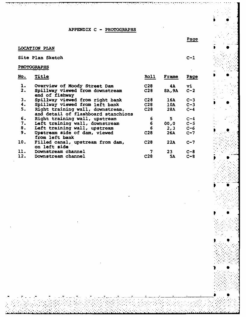
APPENDIX C - PHOTOGRAPHS
Page
LOCATION PLAN I 0
Site Plan Sketch C-i
PHOTOGRAPHS
No. Title Roll Frame Page
1. Overview of Moody Street Dam C28 4A vi2. Spillway viewed from downstream C28 8A,9A C-2
end of fishway3. Spillway viewed from right bank C28 16A C-34. Spillway viewed from left bank C28 10A C-3 05. Right training wall, downstream, C28 28A C-4
and detail of flashboard stanchions6. Right training wall, upstream 6 5 C-47. Left training wall, downstream 6 00,0 C-58. Left training wall, upstream 6 2,3 C-69. Upstream side of dam, viewed C28 26A C-7 -
from left bank10. Filled canal, upstream from dam, C28 22A C-7
on left side11. Downstream channel 7 23 C-812. Downstream channel C28 5A C-8
Ip S
P 0
I. •
., S
_ _ _ _ _ 0 % -" " .
'V AL -C -- N. -. . . . . . ..7
'Aa w
%~ k
ILI
L-2,
/~ I ~I * a *
ItI
I 1 O Ii--k31

II
11 F It
I j-
all1toff
' j A~ I_ a
-- t~L
91 tLt ON31a11 111011. in
IAI
fl
91 ON , -N -1.

.. . ..... . . . ..1 .v
- -~ I~dMct~!! ee4wth
To 5e- i.
_ _ B-7
DA . *.--4-.*s
* 6
-4Ctb .. du ......
Van I
Attach* lketcho ada twozth.3frm seoting section. fande pln8h a
EM -a--- a.L 7, 7o
-NIN
11.-
Atac seth f amto~ s or soin sctonan panB'' 1" het
7-0LE ~eLA5 *arci r~o'i- I'mO:.f * - L
IJIIE' 'M ~AI.. TaB-6f
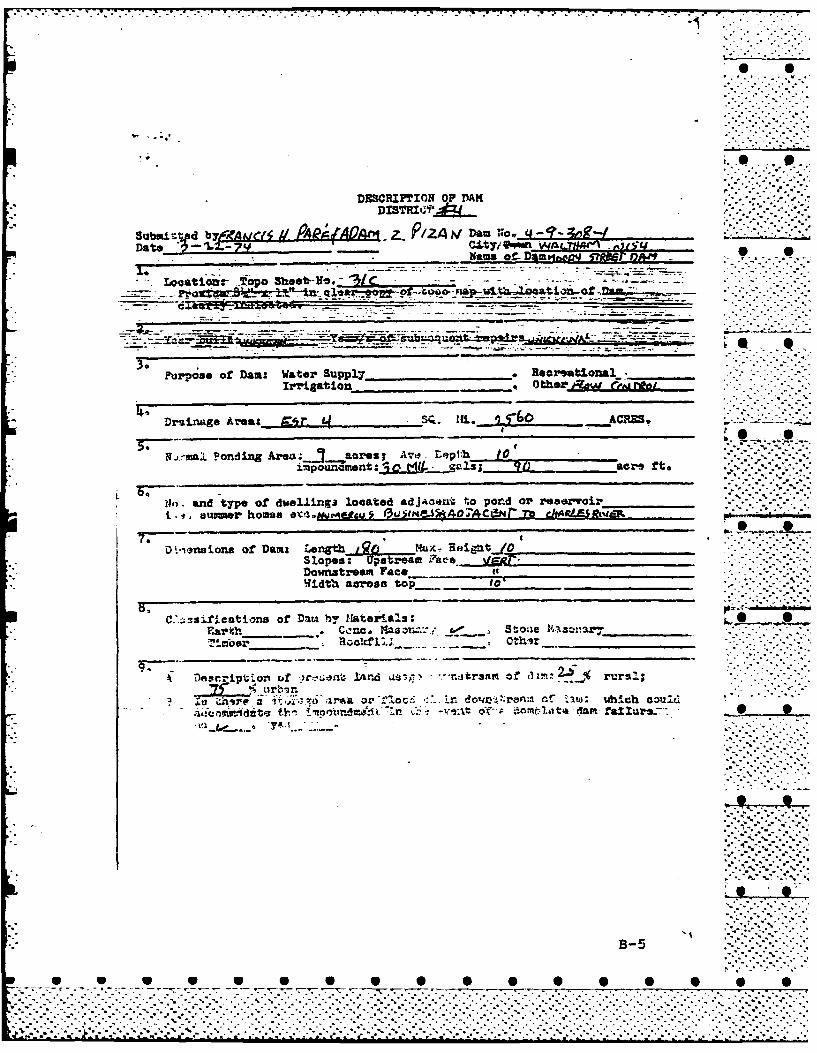
DESCRIPTION OP DAMI
Submit- d byE C( 11 PAggAO-Z. . PIZ4i DamN~O. ~___Date -L-yC.y F Z 5~
mame ofpmg~ pwr 0m
Looatlonr Tpo Shoot-.
Purpose of Daa: Water Suppl7 *Rea tional____
Drsinage AreaL: Q'r.L ~ i. ACRE5.
I*rin. ond5ing Area.....ia..cres; Are! Bepth 10
11r. and type of dwel.Linga located adjaaIut to porAd or reservoir______I j uummer home *O'.1 QAjuU & 31x,5I AAC N I- Th ghARSRVEF.(d
ol.iorw ions of Dams Ler %tLIux***N ErzigftJO1Sl opeesi pe ream lac-e VERT-.
Width aoroso top_1
C:.; _si4fieat.2nq of Damr. by Mtaterials:Ea. C,:nc. Maar & Stone 'snir L.. S'"leoar_____ Rocl. Othi __________
or _ Roo
ur.4..-.
B-5
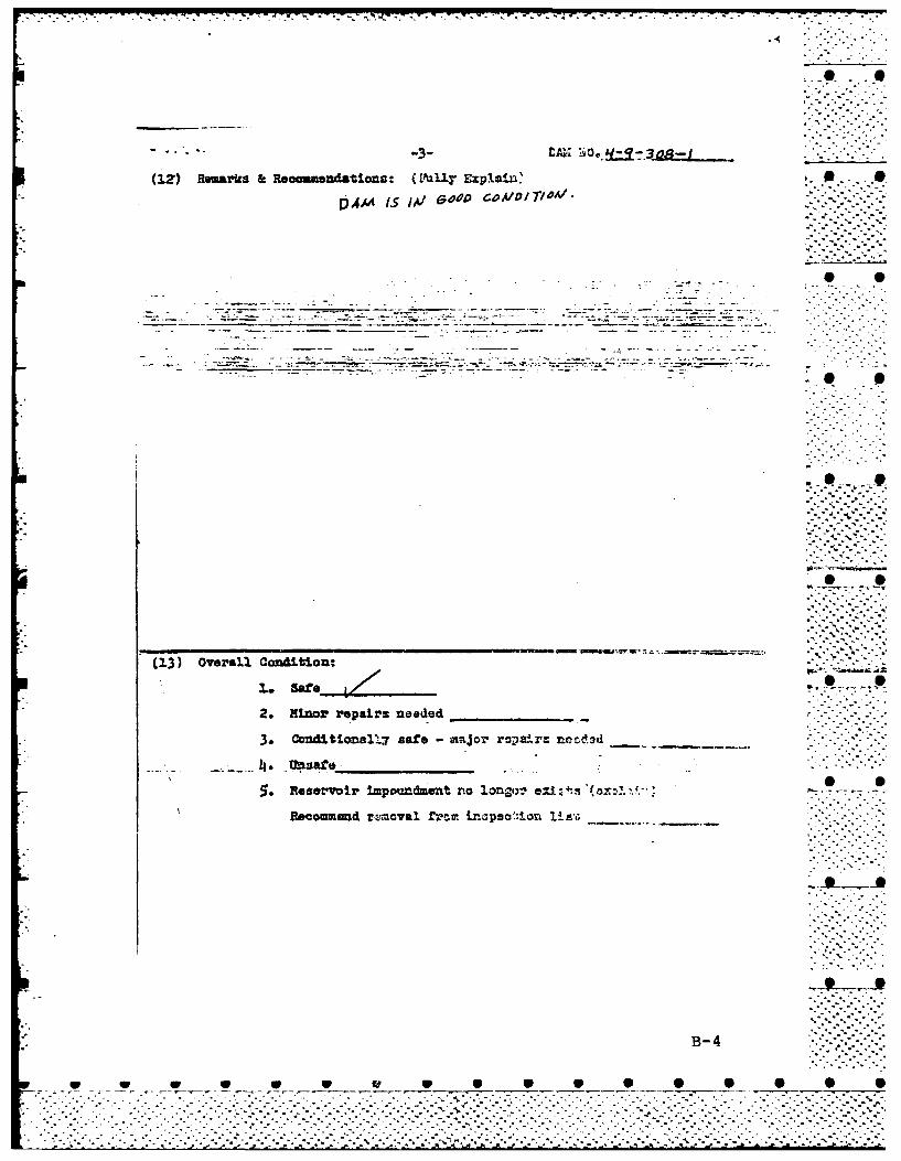
(12) Remarks & Reomaandations: (D'ia11y Explain'~
(13) Oveal cg ndioA/IT/uA/
Pleer-i -- por 0
t r.0 .or.g 9
Recommend~~~~-- rzrcvlf-mJrao-.onla
B-4
Ni 0
9. Upstream side of dam, viewed from left bank
V-
10. Filled canal, upstream from dam, on left side -
C-7
S~ ~ 1P V S S S S S

11 Dontra channe
Ip~~~~ a0
...... .... .d
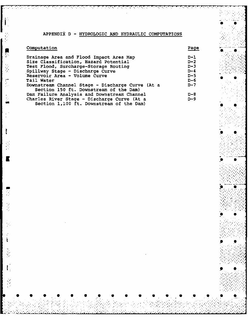
[-' -APPENDIX D - HYDROLOGIC AND HYDRAULIC COMPUTATIONS
Computation Page
" Drainage Area and Flood Impact Area Map D-1Size Classification, Hazard Potential D-2Test Flood, Surcharge-Storage Routing D-3
- Spillway Stage - Discharge Curve D-4Reservoir Area - Volume Curve D-5
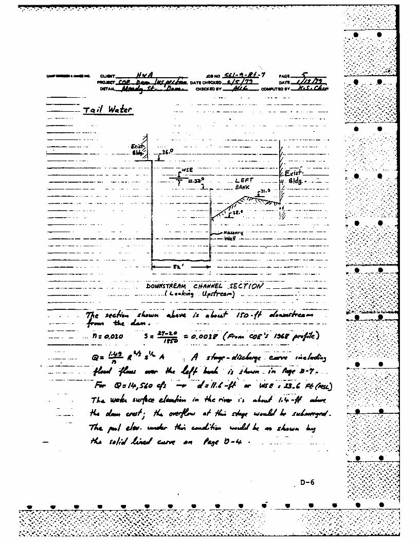
- Tail Water D-6 •. Downstream Channel Stage - Discharge Curve (At a D-7
Section 150 ft. Downstream of the Dam)Dam Failure Analysis and Downstream Channel D-8Charles River Stage - Discharge Curve (At a D-9
Section 1,100 ft. Downstream of the Dam)
ow. ..
I - S o . .'
• - "-,-?:2 S-i:i
.. .. ..
. . -. -.. .. . . . ...
. . . . . . . . . . . . . . . . . . . . . . . . . . . . . . . . . . . . . .
- ,tirPRom)ICEO AT GOVERFMENT rFxpNe
----- f - -e-S
PAMIZT PAC e
4 4f
C3-,~'o~ *~
~~IS CAPDRSER&McE ICoIttn EnOeeRO___Boston Mass
i~z __________________
iz~l S. . . . . . . . . . . . . . .
...- ,. . . . E
T- 0, IN .. ~*. A-** -

III IODLJCEO kr 0M&i6kT xfJtPN
~~ FLOOD IMPACTAt~ L~~ ARE~A eOUNPAR'(
T. PVO ADLE IMPACZT A9.EAPCOM DAM FAILUP-E
!2--AU E: 1,241000
4ASIN j . s' > X-~ - -
-. . AZEA
EK)INAqC
P_ UA-a
ItD-
%*.* .-.
ifta~~ DATE 04=S A LCO AE 7
MnAJI CHWAID By __j~1L Ca~Wurmo
- - - -i A ~ I - - - - -.
-. If~~draujacf He(I e_____ __
gm-- Leda4amwre
APAVtf*4rIb.3.
____ ____ ____D -26
"7*:"

MWAECT....O..fAin...4 4CAWI DATLICNECKED OAT~~ L
loop SACE ce411q4 4/7. i-( ',vrmekp/ v zd *
Atok/s: (t 6T* a/s /rv,' Wes ejd4/,4./ I.; COE
~Cual % oi."~ &#v,'a eeltk /4w Ea4
St~rc~arge li A-~j -4~i .. . -. -
77
Or, a 14, roo cir W.E 4.(MSL)~4 S4, ,ek~
Swvc*g." 9E Vlume: 4.600o-,4, w3, so .cf (. f9-es-vs
117 TO
a. ca.: jw4,$1ttv 7 .
0 ..
- D-3
%- '

mmuw e~.nLaa&M tf4~ OATS C)4CKUD..&ELZL... OAT /t i
04w
w _ w __ . .-. v_ - -v.- __ w w 0 0
. . . . .. -.~\ .- _ ._ ..... --.- 4 .~ .
PfONJECTa..lm...bghm DAT! CHECKED .. &41 . DATV 4a. zDETAIL MAMJa tJ. CHECKED Sy AU COMPUTE By r
* ---. -. ~------ --. - -*--------(J4n
lool
__ __- 71127iZ.1 - -~. ~~44*At
-oD-5
WSS
cina~EF l Ah 6DETI_*~U~~**ME***EJ~~LZUE cHcKD BANK9
AA A q HcE Y.....~. OPTDI
_oisvh c 4-#// -mcro
47 - .46.. .------.- WS f J3. -.
______ x~mAtAI
7X___l w~ G - . -..------. . .- w*
_____*/,; -w - .r2 ' - -------------....-. S
.bOWNTREAA CM,4D-6
0~ Urdvreas.) - V

CAl&G AICG CLIENT #,A JO 140e-a h-Z V AGMROJCT..apf.f 110, DATE CHECKED DATEAZ..A.. DAT
DETAIL Adng f/ CH~ECKED BY 4" CO.UF
To---
_ _ ___ _ __'\.. ---- -__ --
4Jlb_ _ _ _ _ _ _
I.. V1NI614
S. ~ D-7
_ __ _ -- 0 1 1 S
cin~~mm s-rn T Ala A JOB NO AViINIL. PAGEPRATemCOAT~IHEOKII O4C ATZ!.A ,/.~
CI4SCK BYx mycompurac S , 'Z.4,L.CdIL. .
ba WF,/' W1. A4o /7
Dow"t Le4wedv 4..ftd. e, a
cl) hitf4 417 ~ f 9.
g~~. ~ /Z04400 -11* L-I'
VIAV ADS0(I~ a /0, FPO CA/0 ee.
lawE i 4 f/e~ae.t 30o Lw4 j& 4 ar
D-8
. . . . . . . . . . . .0

CAW DRESSER & MCKEE CLV TAW ...... ,..... JOB NO. oricI- -t4 itG
Grwmwqt BEguw 0 Orjc ,& iATE CHECKE -/,y 14.ZL.....Boos,.Mm. owrAs. Aiaj4 r4, Ibe.. CHECKED BY.....,t6... comwum BY
_ _ _ _ _ _ _Q
I _ _ _--. - - ___ _ AD
-D-9

PRJC DATE CHECKED OATLX4Z........ DATE0DETAIL M iIL *~CHECKED BY .. U~..COMPUTED By
____ _4444
Le AIf A -of4 44c( at-,~ cL~iO ._prA aMi. 1A~ 4.
a.d ~ o .( . ...... . wr ..f .h .~# .S ,

* S
APPENDIX E - INFORMATION AS CONTAINED IN
THE NATIONAL INVENTORY OF DAMS
* 0
* 0
1~* S
* S
* S
U ... * S
* S
S S
[ S S
* S S S S S S S S S S S S S 5 0
...........................................................................................................................................................................................

rCr
.44
-. ILw
.'~cc
VL to Zimole
-Z:4.~
-imI
I I <- Iici
H~~ KSo)
1 7 ~J i~' -
p
I I''~.~I2
D CT I.