ad-a251 223 - defense technical information center 223 1111l1.1, li lll 1 =1 i1t |11 l .. cdrl no....
TRANSCRIPT

ITT-A/CD NO. 31706004-3 24 AUGUST 1990
INSTALLATION AND ACCEPTANCE TEST SPECIFICATION(FINAL)
AD-A251 2231111l1.1, li lll =1 1 I1T |11 l .. CDRL NO. B004
FOR
SINCGARS
AIRCRAFT INTEGRATED COMSEC DEVELOPMENT(PHASE III)
CONTRACT NO. DAAB07-88-C-T041
PREPARED BY
ITT-AEROSPACE/COMMUNICATIONS DIVISION1919 WEST COOK ROAD
P.O. BOX 3700FORT WAYNE, INDIANA 46801
FOR
UNITED STATES ARMYCOMMUNICATION-ELECTRONICS COMMAND
FORT MONMOUTH, NEW JERSEY 0770392-13150
)i
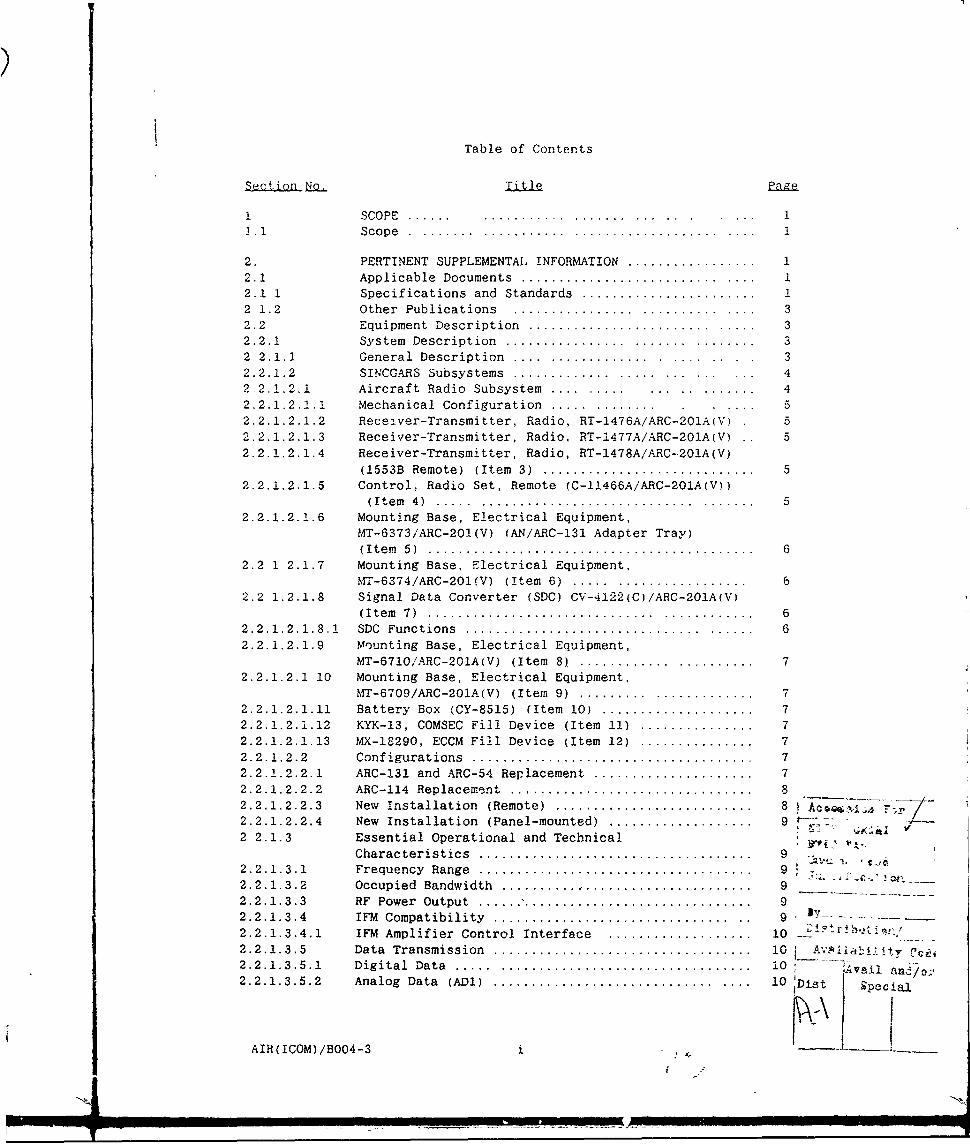
Table of Contents
Section No. T Page
I SCOPE ...... ............. ..... ... .... .. 11.1 Scope .............................................. 1
2. PERTINENT SUPPLEMENTAL. INFORMATION ................... 12.1 Applicable Documents .... ...................... ...... i2.1 1 Specifications and Standards ....................... 12 1.2 Other Publications ................. ........... .... 32.2 Equipment Description ......................... ..... 32.2.1 System Description ................ ........ ........ 32 2.1.1 General Description .... .............. .... .... 32.2.1.2 SINCGARS Subsystems ........................ .... ... 42.2.1.2.1 Aircraft Radio Subsystem ........................ 42.2.1.2.1.1 Mechanical Configuration ............... .... 52.2.1.2.1.2 Receiver-Transmitter, Radio, RT-1476A/ARC-20iAlV) 52.2.1.2.1.3 Receiver-Transmitter, Radio. RT-1477A/ARC-201A(V) . 52.2.1.2.1.4 Receiver-Transmitter, Radio, RT-1478A/ARC-20!A(V)
(1553B Remote) (Item 3) ............................. 52.2.1.2.1.5 Control, Radio Set, Remote (C-11466A/ARC-201A(V))
(Item 4 ) ...... ............................. ........ 52.2.1.2.1.6 Mounting Base, Electrical Equipment,
MT-6373/ARC-201(V) (AN/ARC-131 Adapter Tray)(I te m 5 ) ..... ........ ... .... ... ...... ............. . 6
2.2 1 2.1.7 Mounting Base, Electrical Equipment,MT-6374/ARC-201(V) (Item 6) ...... ................. 6
2.2 1.2.1.8 Signal Data Converter (SDC) CV-4122(C)/ARC-201A(V)(Item 7 ) ............................... ............ 6
2.2.1.2.1.8.1 SDC Functions ... ............................ ......... 62.2.1.2.1.9 Mounting Base, Electrical Equipment,
MT-6710/ARC-20IA(V) (Item 8) ....................... 7
2.2.1.2.1 10 Mounting Base, Electrical Equipment,MT-6709/ARC-201A(V) (Item 9) .......... .............
2.2.1.2.1.11 Battery Box (CY-8515) (Item 10) ..................... 72.2.1.2.1.12 KYK-13, COMSEC Fill Device (Item 11) ................ 72.2.1.2.1.13 MX-18290, ECCM Fill Device (Item 12) ...............2.2.1.2.2 Configurations ...................................... 72.2.1.2.2.1 ARC-131 and ARC-54 Replacement ....................... 72.2.1.2.2.2 ARC-114 Replacement ................................ 82.2.1.2.2.3 New Installation (Remote) ........................... 8 Ac .i -2.2.1.2.2.4 New Installation (Panel-mounted) ........... ....... .. /
2 2.1.3 Essential Operational and Technical
Characteristics .. .................................... 92.2.1.3.1 Frequency Range .................................... 92.2.1.3.2 Occupied Bandwidth ................................. 92.2.1.3.3 RF Power Output ..................................... 92.2.1.3.4 IFM Compatibility ... ............................ ... 9 -
2.2.1.3.4.1 IFM Amplifier Control Interface .................... 10 1 ir . i2.2.1.3.5 Data Transmission .................................. 10 i Av Iil litv C2.2.1.3.5.1 Digital Data ....... ................................ 10 12.2.1.3.5.2 Analog Data (ADl) .............................. .... 10 Dist 4 pecial
AIR(ICOM)/BO04-3 i

Table of Contents - continued
2.2.1.3.5.3 TACFIRE (TF) ATHS Data (1200/2400 Hz FSK atData Rate of 600 or 1200 bps) ...................... 10
2.2.1,3,5.3.1 Error Control ......................... .... ....... 10
2.2.1.3.6 Built-In-Test ............................ ... ....... 11
2.2.1.3,7 Duty Cycle ......................................... 112.2.1,3.8 Modes of Operation ................................. 112.2.1.3.8.1 Plain Text (PT) .................................... 112.2.1.3.8.2 Cipher Text (CT) With COMSEC ....................... 112.2.1.3.8.3 Retransmission, PT/CT With or Without
Electronic Counter-Countermeasures (ECCM) .......... 112,2.1,3,8,4 Frequency Hopping Operation in PT and CT ........... 112.2.1.3,8.5 Data Transmission .................................. 112.2.1.3.8.5.1 18 kbps Digital Transmission ............. ......... 11
2.2.1.3.8.5.2 Low Rate Digital Transmission (600 bps to 4800 bps) 122.2.1.3.9 Preset Channels .................................... 122.2.1.3.9.1 Manual Mode ........................................ 122.2, 1.3.9.2 FH Capability ...................................... 122.2.1,3.9.3 FH Operational Mode ................................ 122.2.1.3,9.4 Communication Security (COMSEC) .................... 122.2.1.3,10 Size and Weight .................................... 122.2.1.3.11 Frequency Accuracy and Stability ................... 132.2,1.3.12 Supply Voltage ..................................... 132.2.1.3.13 Battery Selection .................................. 132.2.1.3.14 Tclerance to Load Variation ........................ 162.2.1.3.15 Receiver Selectivity ............................... 162.2.1.2.16 Receiver Input Circuit Protection .................. 162.2.1.3.17 Receiver Audio Output .............................. 162.2.1.3.18 Tone Operated Squelch .............................. 162.2.1.3.19 Receiver Delay Times ............................... 16
2.2.1.3.20 Transmitter Noise Level ............................ 162.2.1.3.21 Transmitter Audio Input Sensitivity ................ 162.2.1.3.22 Sidetone ........................................... 172.2.1.3.23 Transmitter Delay Times ............................ 172.2.1,3.24 Control Panel Illumination ......................... 172.2.1,3.24,1 Aircraft Control Panel Illumination ................ 172.2.1.3.24.2 Signal Data Converter Front Panel Illumination ..... 172.2.1.3.25 Electronic Counter-Countermeasures (ECCM) .......... 172.2,1.3.26 TEMPEST ............................................ 172.2.1,3.27 Aircraft (Amplitude) Homing ......................... 172.2.1.3,27.1 Homing Sensitivity ....................... .......... 172.2.1.3,27,2 Homing Mode Resolution ............................. 17
2.2.1.3.27,2.1 Station Approach Indication .......... ........ 17
2.2,1,3,27.2.2 Equal Amplitude Dynamic Range ...................... 182,2.1.3,27.2.3 Deflection Dynamic Range ........................... 182.2,1.3,27,2,4 Deflection Symmetry ................................ 182.2.1.3.27.3 Communication While Homing ......................... 182.2.2 Nuclear Survivability .......... ......... 182,2.2.1 Nuclear Survivability Mission Description .......... .18
AT"TrOM)/nO04.1 1i

Table of Contents - continued
SetinNoTil Pg
2.3 List of Acronyms and Abbreviations Used inThis Document....................................... (
2.4 Operational Description...............................202.4.1 Aircraft Radio Subsystem..............................202.4.1.1 Panel. Mounted RT......................................202.4.1.1.1 Detailed Descriptions.................................222.4.!.2 Dedicated Remote RT...................................322.4.1.3 1553B Remote RT...................................... 342.4.2 Remote Control Unit...................................342.4.3 Signal Data Converter.................................372,4.4 SDC Rear Panel Switches...............................392,5 Self Test Description.................................39
3.0 REQUIREMENTS..........................................423.1 General................................................423.1.1 Acceptance.......*....*.......*................,...........423.1.2 Responsibility for Miscellaneous Components...........423.1.3 Quality Assurance.....................................423.1.4 Report s...............................................423.1.5 Radio Frequency Assignment............................423.1.6 Check-off List........................................423.1.7 Equipment Non-Compliance..............................423.1.8 Equipment Under Warranty..............................473.1.9 Procuring Activity Approval...........................473.1.10 Test Equipment Calibration............................473.1.11 Electronic Subsystem Certification....................473.1.12 Instrumentation.......................................473.1.13 Edectromagnetic Compatibility.........................473.1.13.1 Critical Frequencies..................................483.1.14 Equipment Components..................................493.1.15 Additional Equipment Required.........................493.1.16 Test Equipment Required...............................503.2 Installation......................................... 523.2.1 General...............................................523.2.2 Electrical Bonding....................................523.2.3 Antennas..............................................523.2.4 Control Panels........................................533.2.5 Mountings.............................................533.2.6 Precautions...........................................533.2.6.1 Voltage-Standing-Wave Ratio (VSWR) and
Continuity Checks.....................................533.2.7 Power Supply Requirements.............................533.2.8 Normal Duty Cycle.....................................533.2.9 Environmental Requirements............................533.2.10 Pressurization........................................543.2.11 Cooling.............................................. 543.2.12 Electromagnetic Interference (EMI) Characteristics 54
3.2.13 Location Considerations...............................55
3.2.14 Detailed Requirements................................55
ArR(TConM)/B004-3 iii

Table of Contents - ccntinued
Section No. Title Pg
3.2.14.1 Panel Mounted Receiver-Transmitter, RT-1476A ........ 553.2.14.2 Dedicated hemote Receiver-Transmitter RT-1477A
and Remote Control Unit, C-11466A ................... 55
3.2.14.3 MIL-STD-1553B Receiver-Transmitter, RT-1478A ........ 553.2.14.4 Remote Control Unit, C-11466A ....................... 553.2.14.5 Signal Data Converter .. ....... ...................... 56
4.0 QUALITY ASSURANCE PROVISIONS ........................ 57
4.1 Responsibility for Inspection ................ ....... 57
4,2 Classification of Inspections ....................... 57
4.3 Installation Examination . ........................... 57
4.3.1 Installation Drawings ............................... 574.3.2 External Wiring Diagrams ................... ......... 57
4.4 Bench Tests ..... ..................... ............. 574.4.1 General . ............................................ 574.4.1.1 Test Cable Diagrams . ................................ 78
4.4.1.2 Standard Conditions . ................................ 784.4.1.3 Input Power . ........................................ 78
4.4.2 Visual and Mechanical Inspection .................... 784.4.3 Test Procedures . .................................... 844.4.3.1 Equipment Setup . .................................... 84
4.3.2 Power On . ........................................... 86
4.4.3.3 Control/Programming Tests .......................... 874.4.3.3.1 Frequency Control .................................. 87
4.4.3.3.2 Preset Control . ..................................... 884.4.3.3.3 Time Command Control................................ 884.4.3.3.4 ECCM Control ....................................... 894.4.3.3.5 Panel Illumination Control .................. ........ 894.4.3.4 Transmitter Tests . .................................. 904.4.3.4.1 Power Output and Sidetone Tests .................... 904.4.3.4.2 Frequency Check . .................................... 904.4.3.4.3 RF Carrier Deviation Test ........................... 934.4.3.5 Receiver Tests . ..................................... 95
4.4.3.5.1 Analog Sensitivity . ................................. 954.4.3.5.2 Squelch and Volume Control Tests .................... 964.4.3.6 Homing Tests ....................................... 1004.4.3.7 Verification of IFM AM-7189A Amplifier Control
Signals ............................................ 1024.4.3.8 Single Channel System Tests ........................ 1044.4.3.8.1 Plain Text Voice ................................... 1044.4.3.8.2 Cipher Text Mode ................................... 1044.4.3.8.3 Frequency Shift Keying (FSK) ....................... 1044.4.3.9 Frequency Hop System Test (Plain Text Voice) ....... 1074.5 Preflight Tests .................................... 1094.5.1 Electrical Power Source ....................... ..... 110
4.5.2 Test Equipment Required ............................ 1104.5.3 Receiver Tests ..................................... 1104.5.4 Transmitter Tests .................................. 1124.5.4.1 Forward and Reflected Power ........................ 112
AIR(ICOM)/BO04-3 iv

Table of Contents -continue.
4.5.5 SC Communication Check '...............................11:4.5.5.1 Radio Performance in SC/PT............................1124.5.5.2 Radio/SDC Performance in SC/CT........................1134.5.6 FH Communication Test.................................1134.5.6.1 Radio Performance in FH/PT....................... ... 1134.5.6.2 Radio/SDC Performance in FH/CT........................1134.5.7 Retransmission Check..................................1134.5.8 Homing Tests..........................................1144.6 Flight Tests..........................................1144.6.1 Communication Test....................................1154.6.2 Homing Tests..........................................115
5.0 EXTERNAL CONNECTORS AND SIGNAL CHARACTERISTICS.......116
APPENDIX A...............................:.............-APPENDIX B............................................B--1
ATPI(Trnt) flfl04 3

List of Tables
Table No. Title Pg
2.2.1.3.10-1 Size and Weight for Aircraft SINCGARS Equipment ... 14
2.4.1.1.1-1 Preset Switch Functions ............................ 27
3.1.14-1 Equipment to Be Tested for AN/ARC-201A(V)Aircraft System . .................................... 49
3.1.16-1 Test Equipment and Accessories ..................... 51
5.0-1 List of Connectors and Part NumbersIncluding Mating Connectors ........................ 117
5.0-2 Connector Pin Descriptions for Ji and J2 ofRT's (RT-1476A, RT-1477A, and RT-1478A) ........... 118
5.0-3 Connector Pin Desbription for J3, J4, J5, and J6of RT's (RT-1476A, RT-1477A, and RT-1478A) ......... 119
5.0-4 Connector Pin Descriptions for J7, J8, and J9(RT-1478A Only) .................................... 120
5.0-5 Connector Pin Descriptions for Jl of
Remote Control Unit (C-11466A) ..................... 121
5.0-6 Connector Pin Descriptions for the SDC (CV-4122) ... 122
5.0-7 Connector Pin Descriptions forSDC Adapter Tray (MT-6710) ......................... 128
5 0-8 Connector Pin Descriptions for Jl onAdapter Tray Mounting Base ......................... 129
5.0-9 Connector Pin Descriptions for J2, J3, J4. and
P3 of Adapter Tray Mounting Base .................. 130
AIR(ICOM)/BO04-3 vi

List of Figures
I Figure No. Title Pe
2.4.1.1-1 ICOM RT-1476A Front Panel........................... 21
2.4.1.2-1 Dedicated Remote RT Unit Front Panel ................ 33
2.4.1.3-1 1553B Remote RT Front Panel . .. . .. . . . . .. . . . . . .. . . . . . 35
2.4.2-1 Radio Set C-11466A Front Panel ...................... 36
2.4.3-1 SDC Front Panel . .................................... 38
3.1.6-1 Check-Off List for Bench Tests ...................... 43
4.3.1-1 Installation Control Drawing,Local Control RT-1476A . ............................. 58
4.3.1-2 Installation Control Drawing,Dedicated Remote RT-1477A ........................... 59
4.3.1-3 Installation Control Drawing,1553B RT-1478A . ..................................... 60
4.3.1-4 Installation Control Drawing,Radio Set C-11466A . ................................. 61
* 4.3.1-5 Installation Control Drawing,SDC - Panel Mount . .................................. 62
4.3.1-6 Installation Control Dwg,MT-6373 with RT-1477A/ARC-201A(V) .................. 63
4.3.1-7 Installation Control Dwg,MT-6374 with RT-1477A or RT-1478A/ARC-201A(V) ...... 65
4.3.1-8 Installation Control Drawing,
Adapter Tray MT-6373 with RT-1477A .................. 67
43.1-9 Installation Control Drawing,SDC on Hard Mount tMT-6709) ........................ 68
4.3.1-10 Installation Control Drawing,SDC on Adapter Mount (MT-6710) ..................... 69
4.3.2-1 Interconnect Radio System Drawing,Panel Mounted Radio, Adapter Mounted SDC, And Z-AHP,For Existing Installations .......................... 70
4.3.2-2 Interconnect Radio System Drawing,Dedicated Remote Radio, Adapter Mounted SDC,And Z-AHP. For Existing Installations ............... 71
AIR(ICOM)/BO04-3 vii

List of Figures - continued
ie -_itl
4.3.2-3 Interconnect Radio System Drawing,Dedicated Remote or Panel Mounted Radio WithRemote Control Unit, Panel or Hard Mounted SDC.And Z-AHP. For New Installations ................... 72
4.3.2-4 Interconnect Radio System Drawing,Panel Mounted Radio And Panel Mounted
SDC, For New Installations ...................... ... 73
4.3.2-5 Interconnect Radio System Drawing,
MIL-STD-1553B Radio, Remotely Mounted SDC. AndZ-AHP, for New Installations ....................... 74
4.3.2-6 Interconnect Radio System Drawing.MIL-STD-1553B Radio, Panel Or Hard Mounted SDC,For New Bus-Controlled Installations ............... 75
4.3.2-7 wiring Diagram for MT-6373 Mounting Base .......... 76
4.3 2-8 Wiring Diagram for SDC Adapter Mount .............. 77
4.4.1.1-1 Test Cable No. 1 (RT-1477A Radio to
C-11466A Remote Control Unit ....................... 79
4.4.1.1-2 Test Cable Set No. 2 (RT-1476A to SDC) ............. 80
4.4.1.1-3 Test Cable No. 3 (Intercom to SDC and Headset) ..... 81
4.4.1.1-4 Test Cable No. 4 (RT-1478A to MIL-STD-1553B
Exerc iser ) ......................................... 82
4.4.1.1-5 Test Cable No. 5 Wiring Diagram for FSK Tests
(Section 4.4.3.8.2) ................................ 83
4.4.1.1-6 Test Cable No 6 (Jumper Cable for ConnectingMK994/AR System Cable, CS-10889/U. to RTSystem Connector J1) ............................... 83
4.4.3.1-1 System Test Sttup . .................................. 85
4.4.3.4.1-1 Sidetone and Power Output Test ..................... 91
4.4.3.4.2-1 Frequency Check . .................................... 92
4.4.3.4.3-1 RF Carrier Deviation Test .......................... 94
4.4.3.5.1-1 Receiver Sensitivity Tests ......................... 97
4.4.3.5.2-1 Receiver Squelch Tests .............................. 98
4.4.3.5.2-2 Audio Combiner Network (Locally Manufactured) ...... 99
4.4.3.6-1 Test Setup for Homing Tests ........................ 101
AIR(ICOM)/B004-3 viii

List of Figures - continued
SFigure No. Title Pa~e
4.4.3.8.1-1 System Tests - Plain Text SC/FH .................... 105
4.4.3.8.2-1 System Tests - Single Channel FSK .................. 106
4.5.3-1 Typical Aircraft installation of RT(All probable installations not shown) ............. ill
ATP(TrOMI/RfO4-3

MILITARY SPECIFICATION
INSTALLATION AND ACCEPTANCE TEST SPECIFICATION
FOR
SINCGARS AIRCRAFT INTEGRATED COMSEC DEVELOPMENT
(PHASE III)
This specification is approved for use by AVSCOM, Department of the Army.
and is available for use by all departments and agencies of the Department
of Defense.
1. SCOPE
1.1 Scope. This specification provides installation, equipment
performance. engineering production approval instructions and requiremients
for installation and testing of the AN/ARC-201A(V) Aircrait system and
associated equipment in prototype and production model aircraft. The
MK-994 test set and auxiliary test equipment will be employed during many
phases of the test program as specified herein.
2. PERTINENT SUPPLEMENTAL INFORMATION
2.1 Applicable Documents.
2.1.1. Specifications and Standards. The following soecifications andstandards form a part of this specification to the extent specified herein.Unless otherwise specified. the issues of these documents shall be thoselisted in the Department of Defense Index of Specifications and Standards(DODISS) and supplement thereto, cited in the solicitation.
SPECIFICATIONS
Military
MIL-B-5087 Bonding Electrical and Lightning
Protection for Aerospace System
MIL-E-5400 Electronic Equipment. Airborne.
General Specification for
MIL-C-6781 Control Panel, Aircraft Equipment.Rack or Console Mounted
Beneficial comments (recommendations. additions, deletions) and anypertinent data which may be of use in improving this document shouldbe addressed to Commander, US Army Communications-Electronics Command.ATTN: AMSEL-ED-TO, Fort Monmouth, New Jersey 07703-5000 by using theself-addressed Standardization Document Improvement Proposal (DD Form1426) appearing at the end of this document or by letter.
AMSC N/A FSC50985
Distribution Statement A Approved for public release: distribution isunlimited.
AIR/BO04-3

MIL-C-172 Cases. bases. mounting. and mounts.vibration (for use with ElectronicEquipment in Aircraft)
MIL-W-5088 Wiring. Aircraft. installation of
MIL-W-27500 Cable, Electrical, shielded
MIL-E-6051 Electromagnetic CompatibilityF Requirements, Systems
MIL-1-8700 Installation and Test of ElectronicEquipment. in AMrcraft. GeneralSpecification for
MIL-C-45662 Calibration System Requirements
MIL-R-49265 VHF-FM Portion of the Single ChannelW/Appendices Ground and Airborne Radio SubsystemA.. B. C. D, &E (STNCGARS)
MIL-C-55653 Control. Communications System
(C6533( )/ARC)
MIL-C-49227(AV) Control Unit Communications SystemC-10414(V)( )ARC. 1 Aug. 84
MIL-L-85762A Lighting, Aircraft. interior.
Night Vision imaging System (NVIS)Compatible
STANDARDS
Mi litarv
MTL-STD-252 Wired Equipment, Classification of
Visual and Mechanical Defects
MIL-STD-877 Antenna Subsystems. Airborne.Criteria for Design and Location of
MIL-STD-454 Standard General Requirem~ents forElectronic Equipment
MIL-ST-D--461A Electromagnetic interference(Notice 4) Characteris'i s. Requirements for
Equipment Subsys~ems and System
MIL-STD-462A Electromagnetic Trnterference(Notice 3) Characteristics. Measurement of
MIL-STD-704B Electric Power. AL'rcraft.Characteristics and Utilization of
MIL-STD-1553B Aircru.ft internal Timoj Division
Multiplex Data Bus
AIR/B004-32
N'2

MIL-STD-188-iO0 Common Long Haul and TacticalCommunications System TechnicalStandards
MIL-STD-188-114 Digital Interface Circuits.Electrical Characteristics of
2.1.2 Other Publications. The following documents form a part ofthis specification.
CSESD-14 Communications Security Equipment(KY-57/58) System Document, TSEC/KY-57/58 (U)
(CONFIDENTIAL)
AVRADA Performance/Procurement0006F Specifications for Interior
Illumination of Army Aircraft inElectroluminescent (EL) Lighting.6 April 1983
AV-SS-5016-OOIA VHF/FM A4 "ne SINCGARS Radio.29 Jur
(Copies of specifications, standards, drawings, andpublications required by contractors in connection with specificprocurement functions should be obtained from the procuring activity or asdirected by the contacting officer.)
2.2 Eouipment Description. Brief Description and Capabilities of theAN/ARC-201A(V) Aircraft System.
2.2.1 System DescriPtion
2.2.1.1 General Description. The radio System specified hereinprovides VHF-FM radio communications of voice and data. secure or plaintext, in single channel (25 kHz) and the SINCGARS ECCM mode of operationand is intended to replace the equipment and functions now fulfilled by theAN/ARC-54, AN/ARC-131, and AN/ARC-114 and the FM !unctions of theAN/ARC-186. The radio subsystems are configured for rotary and fixed wingaircraft operation. They operate reliably in the varying electrical,mechanical, an-' climatic environments associated with these configurations.SINCGARS provides improved immuniity from the threat of Electronic Warfare,and is interoperable, in all modes of operation, with the SINCGARSManpack/Vehicular radio subsystems identified in 2.2.1.2a through 2.2.1.2gin addition to all the configurations of the AN/ARC-201A(V) listed inSection 2.2.1.2.1. It provides for secure communication of voice and datasignals through int-2facing with the Signal Data Converter.
AIR/B004-3 3
___ m

2.2.1.2 SINCQARS Subsystems. The SINCGARS radio is comprised of thefollowing subsystems:
a. Manpack Radio - RT-1523/VRC
b. Vehicular Radio - Short Range, AN/VRC-87( )(V)
c. Vehicular Radio - Dismountable Short Range, AN/VRC-88( )(V)
( d. Vehicular Radio - Long Range, AN/VRC-89( )(V)
e. Vehicular Radio - Long Range/Short Range, AN-VRC-90( )(V)
f. Vehicular Radio - Long Range with Dismountable Short Range
AN/VRC-91( )(V)
g. Vehicular Radio - Dual Long Range, AN/VRC-92( )(V)
h. Aircraft ARC-201
i. Aircraft ARC-201A
2.2.1.2.1 Aircraft Radio Subsystem. This subsystem incorporates the
basic radio functions provided by Ai/ARC-114, AN/ARC-114A. AN/ARC-54.
AN/ARC-131, and the FM functions of the AN/ARC-186. The subsystem also
provides amplitude homing, and ECCM capability. Guard receiver function isnot required. The Aircraft Radio Subsystem consists of the following
items:
1!M
1 Receiver-Transmitter Radio, Panel Mounted(RT-1476A/ARC-201A(V))
2 Receiver-Transmitter, Radio. Dedicated
Remote (RT-1477A/ARC-201A(V))
3 Receiver-Transmitter, Radio. 15E3B Remote(RT-1478A/ARC-201A(V))
4 Control, Radio Set, Remote(C-11466A/ARC-201A(V))
Mounting Base, Electrical Equipment
(AN/ARC-131 Adapter Tray)
(MT-6373/ARC-201(V))
6 Mounting Base, Electrical Equipment
(MT-6374/ARC-201(V))
7 Converter, Signal Data(CV-4122(C)/ARC-201A(V))
8 Mounting Base, Electrical Equipment(MT-6710/ARC-201A(V), Adapter Tray)
9 Mounting Base, Electrical Equipment(MT-6709/ARC-201A(V), Hard Mount)
AIR/BO04-3 4t
V -'= .... .

10 Battery Box, CY-8515/ARC-20IA(V)
11 KYK-13, COMSEC Fill Device
12 MX-18290, ECCM Fill Device
2.2.1.2.1.1 Mechanical Configuration. fhe aircraft RT chassis isdesigned to accept the removable local control panel, the dedi cated rpmoteinterface module, and the 1553B Remote Control Assembly. in allconfigurations, the objective is to maintain the AN/ARC-l14 envelope. Theback end of the RT unit is similar to thf- AN/ARC-186. All pin functionsthat are identical between the ANARC-186 ano SINCGARS are maintained. Anyadditional signals are accommodated by an auxiliary connector. Thisconnector includes the tune gate, tune c;.o.yk. frequency data, and hop timesignals for interface to an electronicf-. ly tunable antenna or otherauxiliary device. Interface lines to tne IFM Nhich include the 52 MHzfilter switching control line are included in this connector.
2.2.1.2.1.2 Receiver-Transmitter. Radio. 2T-1476A/ARC-201ArV) (PanelMounted) (Item 1). This aircraft RT unit consists ofa panel-mountedreceiver-transmitter unit which will be mounted in the AN/ARC-114 cockpitspace allocation. The Local Front Panel Control Unit which is part of thisRT contains all controls and indicators. The panel-mounted radio iscapable of remote control as specified in 2.2.1.2.1.5. Unless otherwisespecified in 2.2.1.3 the requirements of the Local Control Unit are inaccordance with MIL-C-6781.
2.2.1.2.1.3 Receiver-Transmitter. Radio. RT-1477A/ARC-20IA(V)(Dedicated Reote) (Item 2). For aircraft requiring remote radioinstallation, the local Front Panel Control Unit of the Receiver-Transmitter RT 1476A Panel Mounted, specified in 2.2.1.2.1.2 is replaced bya dedicated remote front panel control interface. This front panelprovides the interface between the radio and the Control Radio Set, Remote.C-11466A, specified in 2.2.1.2.1.5.
2.2.1.2.1.4 Receiver-Transmitter. Radio. RT-1478A/ARC-20IA1V) (1553BRemote) (Item 3). Aircraft outfitted with a 1553B multiplexed data buswill use the aircraft SINCGARS RT with a 1553B Remote Front Panel InterfaceAssembly replacing the local front panel control unit of theReceiver-Transmitter, Radio, RT-1476A, Panel Mounted as specified in2.2.1.2.1.2. The module shall contain all of the 1553B iemote terminalcomponents required for the dual redundant operation and provide for aself-contained microprocessor card programmed to format the MIL-STD-1553Bmessages into recognizable functions and transmit these to the RT unit.Redundant message transmitters and receivers (completely isolated from eachother) are contained in the module. Two processor units are provided toperform redundant encoding and decoding.
2.2.1.2.1.5 Control. Radio Set, Remote (C-]1.466A/ARC-20IAlV)) (Item
4-- The unit provides the control functions for and operate in conjunctionwith the Receiver-Transmitter, Radio, RT-1477A, Dedicated Remote specifiedin 2.2.1.2.1.3. The control and display capabilities of this item shall beidentical to the control and display capabilities of the local control unit
AIR/B004-3 5
of the Receiver-Transmitter, Radio, RT-1476A, Panel Mounted except for theFILL input connector.
2.2.1.2 1.6 Mounting Base, Eiectrca! Enuioment. MT-6373/ARC-2HV)(AN/ARC-131 Adanter Tray.) (Item 5). This item shai± provide the necessarypower connector interfaces, both mechanically and electrically, to permitthe installation of the Dedicated Remote RT unit within the existingIAT-3664/ARC-131 shock-mounting tray. The adapter tray's overallconfiguration shall be similar to the AN/ARC-131 foot print. The dedicatedremote RT unit shall be easily removed from the tray without special tools.This mounting base shall provide both mechanical and electricdl connections
necessary for the attachment of the Aircraft SINCGARS Battery Box (mountinghardware is not provided).
2.2.1.2.1.7 Mounting Base. Electrical Enuipment. MT-6374/ARC-201iV;(Item 6). A mounting base shall be provided on which either the 1553B BusRemote RT or the Dedicated Remote RT unit may be mounted. This tray shallbe made of aluminum and shall not have vibration-shock isolators. Itsmechanical hold-down devices shall permit easy installation and removal ofthe RT units.
2.2.1.2.1.8 Signal Data Converter (SDC) CV-4122(C)/ARC-201AfV)(Itm 7. The Signal Data Converter shall provide for the transmission ofanalog and digital data necessary for operation of Voice, TACFIRE, ATHS. 16kbps, and low-speed digital data. The SDC combines the functions of theAircraft Data Rate Adapter (CV-3885) and the KY-58 COMSEC It iscompatible with existing KY-58 and Z-AHQ configurations and can be remotelycontrolled from the Z-AHP (or compatible device), and locally controlledfrom the front panel of the SDC. It shall meet the same TEMPE.STrequirements as the Ground ICOM SINCGARS radio.
2.2.1.2.1.8.1 Functions. The SDC shall process data signals(analog or digital) in a format identical to the ground ICOM SINCGARSequipment. Data operation with the Airborne Target Handoff System (ATHS)or local TACFIRE Digital Message Device (DMD) is required in aircraftinstallation. When operated in ADI or TF modes with ATHS or DMD. the SDCshall automatically identify whether the intercom transmit signal is voiceor 1200/2400 Hz Frequency Shift Keying (FSK) data and process the signalsappropriately. The following functions shall be provided:
a. Transmit signal identification
b. Receive signal identification
C. FSK demodulation to 600/1200 bps digital format of transmitFSK signal.
d. FSK modulation of 600/1200 bps digital to receive FSK signalformat.
e. Majority logic error correction.
f. Data preamble insertion.
AIR/B004-3 6

g. Interleaving/de-interleaving.
h. Transition insertion in plain text modes.
i. COMSEC '*' function.
j. 16 Kbps transparency.
k. PT voice override (NOT IN ALL CONFIGURATIONS).
2.2.1.2.1.9 Mounting Base. Electrical Equipment. MT-6710/ARC-201AV)
(Item 8). A mounting adapter shall be provided to enable the SDC to beinstalled in the existing MT-3802/ARC. Integrated cables will be provided
the mounting base to make the SDC unit compatible with existing remote
cunfigurations. The tray shall be designed for quick removal of the SDC
unit from the MT-3802/ARC.
2.2.1.2.1.10 Mounting BAse. Electrical Eouinment.MT-6709/ARC-201A(V) (Item 9). The Hard Mount Tray shall be provided for
mounting the SDC in new remote installations. It shall be similar to theMT-6374/ARC-2ClV mounting base bulkhead mounting pattern. The mount shall
be constructed of aluminum and shall have mechanical hold down devices to
provide for the quick removal of the SDC unit from the mounting base.
2.2.1.2.1.11 Daterv Box (CY-8515) (Item 10). The battery box is an
auxiliary piece of aircraft SINCGARS equipment designed to provide
additional system hold-up battery power. The battery box can be mounted
beneath the MT-6373/ARC-201(V) mounting base. Hold up battery power isprovided by five 1.5 volt "C" cells wired in series to an external
connector.
2.2.1.2.1.12 KYK-13. COMSEC Fill Device (Item 1ii. The KYK-13 is afill device designed to be used to fill the SDC with cryptovariables. The
device is connected to a fill port of the SDC. The SDC is placed in LDmode, and fill is initiated by a "push to talk" (PTT) to the SDC.
2.2.1.2.1.13 MX-18290. ECCM Fill Device (Item 12). The MX-18290 is a
fill device designed to be used to fill the RT-1476A, RT-1477A. RT-1478Awith frequency hopping hopset variables. The device is connected to thefill port of the RT. The RT is put into the FH mode, LD position, and fill
is initiated by pressing the LOAD button on the RT-1476A "r.d RT-1477A. The
RT-1478A initiates the fill with a 1553B bus command.
2.2.1.2.2 Configurations. Complete aircraft radio systems shall
exist as combinations of various items described in 3.1.2.1 and are definedin the configurations specified in 3.1.2.2.1 through 3.1.2.2.4.
2.2.1.2.2.1 ARC-131 and ARC-54 Replacement. The following items
shall form the aircraft radio systems which shall be a direct replacementfor the radio sets ARC-131 and ARC-54.
ITEM DIPTION
2 Receiver-Transmitter, Radio, Dedicated
Remnote (RT-1477A)
4 Control, Radio Set, Dedicated Remote (C-11466A)
AIR/B004-3 7

5 Mounting Base, Electrical Equipment (MT-6373)(AN/ARC-131 Adapter Tray)
7 Converter, Signal Data (CV-4122)
8 Mounting Base, Electrical Equipment (MT-6710)(SDC Adapter Tray)
10 Battery Box (Optional) (CY-8515)
11 Kv-13, COMSEC Fill Device
12 M 8290, ECCM Fill Device
2.2.1.2.2.2 ARC-114 Replacement. The following items shall form theaircraft radio system which shall be a direct replacement for the radio setAN/ARC-114 and 114A.
ITEM DESCRIPTI
I Receiver-Transmitter, Radio, Panel Mounted (RT-1476A)
7 Converter, Signal Data (C" -"")2 )
8 Mounting Base, Electrica.L ipment (MT-6710)(SDC Adapter Tray)
10 Battery Box (Optional) (CY-8515)
11 .YK-13, COMSEC Fill Device
12 MX-18290, ECCM Fill Device
2.2.1.2.2.3 New Installation (Remote). The new remote mounted radioset shall be capable of two configurations as follows:
a. 1553B Controlled:
ITEM DESCIPIONk
3 Receiver-Transmitter, Radio, 1553B Remote (RT-1478A)
6 Mounting Base, Electrical Equipment (MT-6374)
7 Converter, Signal Data (CV-4122)
9 Mounting Base, Electrical Equipment (MT-6709)(Hard Mount)
10 Battery Box (Optional) (CY-8515)
11 KYK-13, COMSEC Fill Device
b. Dedicated Control:
TTEM ECITO
2 Receiver-Transmitter, Radio, Dedicated Remote(RT-1477A)
AIJR/BO04-3 8 i
4 Control Radio Set, Dedicated Remote (C-11466A)
6 Mounting Base, Electrical Equipment (MT-6374)
7 Converter, Signal Data (CV-4122)
9 Mounting Base, Electrical Equipment (MT-6709)(Hard Mount)
10 Battery Box (Optional) (CY-8515)
11 KYK-13, COMSEC Fill Device
12 MX-18290, ECCM Fill Device
2.2.1.2.2.4 New Installation (Panel-mounted). The new panel-mountedconfiguration shall consist of the following items:
I ITEM DESCIPTION£Q
1 Receiver-Transmitter, Radio, Panel Mounted (RT-1476A)
7 Converter, Signal Data (CV-4122)
9 Mounting Base, Electrical Equipment (MT-6709)(Hard Mount - Optional)
10 Battery Box (Optional) (CY-8515)
11 KYK-13, COMSEC Fill Device
12 MX-18290. ECCM Fill Device
2.2.1.3 Essential Operational and Technical Characteristics. Exceptwhere specifically indicated otherwise, the following operations/technicalparameters shall be minimum essential characteristics. Unless otherwisespecified, they shall apply to each radio configuration.
2.2.1.3.1 Freguency Range. The frequency range shall be 30 to 87.975MHz channelized in tuning increments of 25 kHz. In addition, a frequencyoffset tuning capability of -10 kHz, -5 kHz, +5 kHz, and +10 kHz shall beprovided in both single channel receive and transmit mode; this capabilityis not required in the ECCM mode.
2.2.1.3.2 Occunied Bandwidth. Ninety-nine percent of the emittedspectrum of analog and digitized voice (16 Kbs) and data shall be containedwithin the 25 kHz channel. The design shall be optimized to support thebasic 16 kbps requirement for the majority of SINCGARS users within a 25kHz channel.
2.2.1.3.3 RF Power OutDut. The RT unit shall provide 1F power outputof +40 dBm (10 watts) ± 2 dB when connected to a 50-ohm load in singlechannel mode and +40 dBm +2, -3 in FH mode at +27.5 Vdc primary power.
2.2.1.3.4 .TFM Comnatibility. The RT unit shall be capable ofoperating in conjunction with the AM-7189A/ARC, improved FM (IFM) poweramplifier for purposes of extending the aircraft communications range ofaircraft operating at nap-of-the-earth altitudes.
AIR/B004-3 9
N(

2.2.1.3.4.1 IFM Amplifier Control Interface. The IFM amplifier.AM-7189A/ARC is a variable power amplifier capable of providing RF outputpower at three levels between 2.5 and 40 watts using the nominal 10-watt RFoutput of the RT unit -s input. The three power levels shall 'e selectedat the RT Control Unit "ocal), Dedicated Remote, or 1553B. Mode controllogic (including a 52 ,itu. filter switching signal, PTT. IFM fault andECCM/SC select signal) shall be contained in the multi-pin connector of theRT Control Unit incorporating the basic functions of the IFM Control Unit(C-11188A!ARC).
2.2.1.3.5 Data Transmission. The SINCGARS system shall beinteroperable/compatible with Army tactical data system. It shall providea residual bit error performance of better than 10-4 in FH and i0-5 in SCmode when handling the following types of data in plain text or cipher textmodes and voice frequency FSK at data rates of up to 1200 bits per second(bps) under normal operating conditions.
2.2.1.3.5.1 DiialData. In the. digital mode. a clock signal shall
be supplied from the SDC to the interface with external data equipment topermit an inherent syn-hronous digital capability at the data rates of 600.1200, 2400, 4800, and 16 kbps. The interface of the data and clock signalswith the external data equipment shall conform to paragraph titled "clock".Equipment, Control, and Timing of MIL-STD-188-100 and MIL-STD-188-114except that an unbalanced data input port is permitted, with a balancedinput port being a design goal. There shall be no polarity reversal ofdigital data over a SINCGARS radio link.
2.2.1.3.5.2 Analog Data (ADI. Analog data shall be treated as anaudio signal. The transmitter input impedance shall be 150 ohms nominal
balanced and the interface level shall be 0 dBm nominal. The receiveroutput impedance shall be 150 ohms nominal balanced and the inteiface levelshall be +17 dBm nominal.
2.2.1.3.5.3 TACFIRE (TF) ATHS Data (1200/2400 Hz FSK at Data Rate of600 or 1200 bos. The SINCGARS radio with the SDC shall interoperate withTACFIRE terminal equipment in plain text mode, and in cipher text mode. InTF (AD2) mode. the FSK data is converted by the SDC to 16 kbps data to betransmitted by the RT. This process is reversed in the receiving SDC.This process improves the error performance of the data link.
2.2.1.3.5.3.1 Error Control. The system design shall provideadditional measures to:
a. TACFIRE F K equivalent bit error rate (BER) of 10-3
shall be attained in a 10-1 channel 16 kbps BER environment.
b. Retain a common interface port for TACFIRE FSK data andvoice, in both plain and cipher text modes. if such measures entail theregeneration of FSK tones at the SINCOARS receiver, such an FSK signalshall be phase continuous with bit boundaries within ± 50 of signal zerocrossings. and the tone frequencies and bit rates shall be within ± 0.1% oftheir nominal values. Bit interleaving shall be provided for burst error
control.
AIR/B004-3 10

2.2.1.3.6 Built-Tn-Test. Built-in-test shall be capable of operatorinitiation to ascertain system status. It shall be utilized by maintenancetechnicians for fault detection and isolation. As a design goal. BIT shalldetect 95% of the faults in the SDC and 90% in the RTs and RCU.
2.2.1.3.7 DutyCrJ . The Radio Set shall meet all the requirementsof this specification when subjected to a duty cycle of one (1) minutetransmit and five (5) minutes receive.
2.2.1.3.8 Modes of Operation. The equipment shall provide thefollowing operating modes for single channel (SC) and frequency hopping(FH):
a. Plain Text (PT), w/wo COMSEC Unit or SDC.
b. Cipher Text (CT), with COMSEC Unit or SDC.
c. Retransmission, PT/CT, SC or FH.
d. Frequency hopping, PT or CT, w/wo COMSEC Unit or SDC
e. Aircraft Homing PT/CT, SC only.
2.2.1.3.8.1 Plain Text (PT). A plain text (non-encrypted)information capability shall be a feature of all radio subsystems.
2.2.1.3.8.2 Cinher Text (CT) With COMSEC. A Cipher Text (CT)capability shall be a feature of each configuration using the Signal DataConverter.
2.2.1.3.8.3 Retransmission. PT/CT With or Without ElectronicCounter-Countermeasures (ECCM). Retransmission shall be accomplished from30 to 87.975 MHz on an fl-f2 basis using the equipment in a retransmitmode. A received signal of fl, whether clear or secure voice, shallactivate a circuit which in turn shall key the transmitter of the other seton frequency f2. In single channel modes. the retransmitting radios shalldetect the type of signal (analog or digital) being received and providefor the automatic transmission of either type signal. All digitalretransmit signals shall be reclocked prior to retransmission.
2.2.1.3.8.4 Freguency Hooing Operation in PT and CT. FrequencyHopping capability shall be possible in PT and CT modes of operation.
2.2.1.3.8.5 Data Transmission.
2.2.1.3.8.5.1 16 kbns Digital Transmission. The SDC shall have thecapability to provide for the transmission and reception of "transparent 16kbps" digital data. The system shall provide for the transmission of thesedata signals in all modes of radio operation: PT SC, PT FH. CT SC. CT FH.In digital "transparent 16 kbps" mode, there shall be no data inversionbetween the audio/data connectors on transmitting and receiving SINCGARSsystems. SDC interface with external digital data equipment shall be inaccordance with MIL-STD-138-114.
The 16 kbps control shall provide a residual BER performance of nogreater than the following at an RF input level of -89 dBm:
AIR/B004-3 11

-LI
I x 10-5 residual BER in single channel modeI X 10-4 BER in FH mode
2.2.1.3.8.5.2 Lcw Rate Digital Trans ssion (600 bns to 4800 bps).The basic control system shall be capable of providing for the transmissionof 600, 1200, 2400, and 4800 bps digital data in all radio operating modes:PT SC, PT FH, CT SC, CT FH. In the transmission of low rate digital data.there shall be no data inversion between the transmitting and receivingSINCGARS system.
The radio shall have the capability of providing the data raterequirements listed below. (Normal room temperature) (Plain Text Mode).
Single Frequency RequiredSignal Type Channel Hopping Performance
4.8 kb/s -111 dBm -110 dBm 10-3 BER2.4 kb/s -113 -112 10- 3 BER1.2 kb/s -115 -114 10-3 BER600 b/s -115 -114 10-3 BER
2.2.1.3.9 Preset Channels.
2.2.1.3.9.1 Manual mode. The radio set shall provide six presetchannels, a manual channel, and a cueing channel (for use in the FH mode ofoperation) for all radio configurations. The preset channels shall selectdiscrete frequencies in a SC mode and FH radio nets in the FH mode. Thepreset channels shall also be held in memory with an internal or externalholding battery.
2.2.1.3.9.2 FH Canailit . The system shall incorporate features toreduce its vulnerability to intercept, direction-finding, and jamming.
2.2.1.3.9.3 FH Operational Mode. All operating modes shall becompatible when loaded with the same FH HOPSET, Common Lockouts, andTRANSEC. FH Fill mode shall be compatible with the Ground ICOM FillDevice.
The Fill Format for the ICOM ECCM module sha! be defined with TRANSEC
appended to the HOPSETS.
2.2.1.3.9.4 Communication Security CCOMSEC. All ICOM radiosubsystems shall be capable of secured communications when utilizing theSignal Data Converter and shall be communication compatible with ARC-201Receiver-Transmitter when equipped with a properly cabled KY-58.
2.2.1.3.10 Size and Weight. The size and weight of the airborneSINCGARS equipment shall not be greater than that specified in Table2.2.1.3.10-1.
AIR/B004-3 12
2.2.1.3.11 Freouency Accuracy and Stability. Frequency error is thedeviation from the indicated channel frequency. The frequency error of thetransmitter and/or the receiver shall be no greater than ±5 ppm (after a 5minute warm-up period) for all environmental and input voltage conditionscontained herein for a period of 2.5 years without recalibration after
I warm-up.
2.2.1.3.12 Suoly Voltage. The equipment shall operate withoutdegradation in specified performance, from 24 to 29 Vdc (27.5 Vdc nominal).At 21 Vdc the radio shall be operable with no degradation in receiverperformance and minimum transmitter power output of 4 watts. At 17 Vdc and30 Vdc. no damage shall occur per MIL-STD-704B. Reverse voltage protectionand transients shall be per MIL-STD-704B, Category B.
2.2.1.3.13 Battery Selection. Batteries required for system operationshall be identical to the batteries used in the Ground ICOM SINCGARSequipment (BA-1372). A memory hold-up battery is used to retainnon-volatile memory when primary power is removed from the RT. Thenon-volatile memory information retained includes ECCM memory. RT presetsand time. Leads are brought out to the RT system connector to permit useof an external "holding battery". The Battery Box (CY-8515) was designedfor this purpose (batteries are not supplied by ITT).
AIR/BO04-3 13
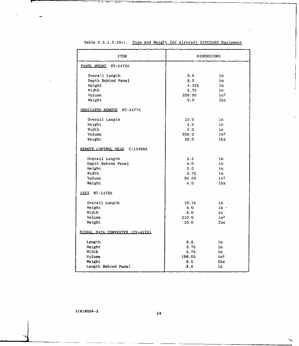
Table 2.2.1.3.10-1. Size and Weiglt for Aircraft SINCGARS Equipment
ITEM DIMENSIONS
PANL MQUNT RT-1476A
Overall Length 9.5 inDepth Behind Panel 8.0 inHeight 4.125 inwidth 5.75 in
Volume 226.00 in3
Weight 9.0 lbs
DEDICATED REMOTE RT-1477A
Overall Length 10.0 JnHeight 4.0 inWidth 5.0 inVolume 200.0 in3
Weight 10.0 lbs
REMQE CONTROL HEAD C-11466A
Overall Length 5.5 inDepth Behind Panel 4.0 inHeight 3.0 in
width 5.75 inVolume 95.00 in3
Weight 4.0 lbs
1553 RT-1478A
Overall Length 10.75 inHeight 4.0 inWidth 5.0 in
Volume 210.0 in3
Weight 10.0 lbs
STGNAL DATA CONVERTER (CV-4122)
Length 9.8 inHeight 3.75 in
Width 5.75 in
Volume 199.00 in3
Weight 6.5 lbsLength Behind Panel 8.4 in
ATR/B004-3 14
N'

Table 2.2.1.3.10-1. Size and Weight !or Aircraft SINCOARS Eciuipment tcont d)
ITEM D IMEN SI ONS
ARC-131 ADAPTER TRAY (MT-6373)
Length 14.5 inHeight 5.6 in
width 5.0 involume 406.0 in3
weight 2.5 lbs
HARD MOUNT MNT-6374)
Length 10.6 inHeight 2.4 inwidth 5.25 involume 133.6 in3
Weight 2.5 lbs
SDC ADAPTER TRAY (MT-6710)
Length 7.75 inHeight 2.30 inwidth 5.05 involume 91.0 in3
Weight 2.5 lbs
SDC HARD MOUNT iMT-67091
Length 10.75 inwidth 7.0 inHeight 1.2 involume 89.0 in3
Weight 2.8 lbs
BATTERY BOX (CY-8515,
Length 7.42 inHeight 1.47 inwidth .3.37 in
volume 37.0 in3
weight 2.0 lbs
5 AIR/BO04-3 1
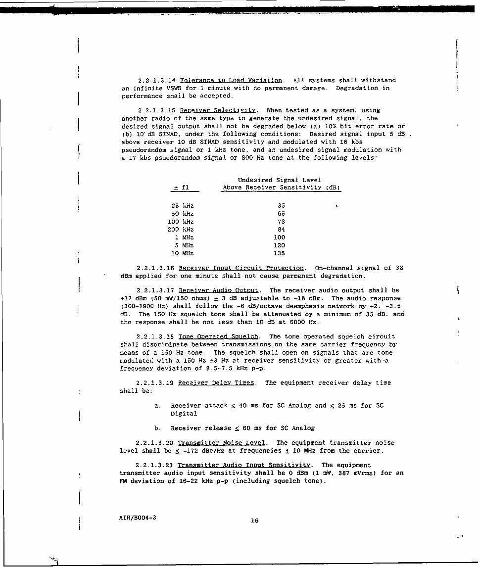
2.2.1.3.14 Tolerance to Load Variation. All systems shall withstand
an infinite VSWR for 1 minute with no permanent damage. Degradation in
performance shall be accepted.
2.2.1.3.15 a]eiver electjLv. When tested as a system, using
another radio of the same type to generate the undesired signal, the
desired signal output shall not be degraded below (a) 10% bit error rate or
(b) l0"dB SINAD, under the following conditions: Desired signal input 5 dB
above receiver 10 dB SINAD sensitivity and modulated with 16 kbs
pseudorandom signal or 1 kHz tone, and an undesired signal modulation with
a 17 kbs psuedorandom signal or 800 Hz tone at the following levels:
_Undesired Signal Level+ fl Above Receiver Sensitivity (dB)
25 kHz 35
50 kHz 65
100 kHz 73
200 kHz 841 MHz 100
5 MHz 120
10 Mhz 135
2.2.1.3.16 Receiver Innut Circuit Protection. On-channel signal of 38dBm applied for one minute shall not cause permanent degradation.
2.2.1.3.17 Receiver Audio Output. The receiver audio output shall be
+17 dBm (50 mW/150 ohms) ± 3 dB adjustable to -18 dBm. The audio response
(300-1900 Hz) shall follow the -6 dB/octave deemphasis network by -2. -3.5dB. The 150 Hz squelch tone shall be attenuated by a minimum of 35 dB. and
the response shall be not less than 10 dB at 6000 Hz.
2.2.1.3.18 Tone Onerated Souelch. The tone operated squelch circuit
shall discriminate between transmissions on the same carrier frequency by
means of a 150 Hz tone. The squelch shall open on signals that are tonemodulate(. with a 150 Hz ±3 Hz at receiver sensitivity or greater with-a
frequency deviation of 2.5-7.5 kHz p-p.
2.2.1.3.19 Receiver Delay Times. The equipment receiver delay time
shall be:
a. Receiver attack e 40 ms for SC Analog and 25 ms for SC
Digital
b. Receiver release _ 60 ms for SC Analog
2.2.1.3.20 Transmitter Noise Level. The equipment transmitter noiselevel shall be r -172 dBc/Hz at frequencies ± 10 MHz from the carrier.
2.2.1.3.21 Transmitter Audio Innut Sensitivity. The equipmenttransmitter audio input sensitivity shall be 0 dBm (1 mW. 387 mVrms) for an
FM deviation of 16-22 kHz p-p (including squelch tone).
AIR/B004-3 16
Na..= m • =m

2.2.1.3.22 Sidetone. The equipment sidetone shall be 3 to 9 dB belowreceiver output. If the transmit power output is low (under 4 watts.nominally) sidetone is disabled.
2.2.1.3.23 Transmitter Delay Times (see 6.3. The equipmenttransmitter delay times shall be:
a. Transmitter attack 50 ms
b. Transmitter release 12 ms
c. Transmit after receive 80 ms
2.2.1.3.24 Control Panel IlluminatiQn. Front panel displays shallconform to the following requirements.
2.2.1.3.24.1 Aircraft Control Panel Illumination. The aircraftlocal control panel and Control, Radio Set, Dedicated Remote shall have
electroluminescent (EL) back-lighting in accordance with AVRADA 0006F.
2.2.1.3.24.2 Signal Data Converter Front Panel Illumination. TheSDC front panel shall meet the requirements of MIL-L-85762A to ensurecompatibility with A1VIS GEN III devices. The panel shall be incandescentbacklit and shall operate from an externally supplied +28 Vdc.
2.2.1.3.25 Electronic Counter-Countermeasures (ECCM. SINCGARS shall
incorporate several features to reduce its vulnerability to intercept.direction finding and jamming. Those features to be provided by the radioequipment shall include the SINCGARS frequency hopping waveform.
2.2.1.3.26 TEMPEST. The TEMPEST requirements are contained inAppendix B of Produc' Specification Receiver-Transmitter Electrical
Equipment, RT-1478A/ARC-201A(V).
2 2.1.3 27 Aircraft (Amplitude) Homing.
2.2.i.3.27.1 oming Sensitivity. The overall sensitivity of thehoming system shall be such that the aircraft can obtain course heading
information and place the RED flags in the dovm position on IndicatorID-1351/A, or equivalent at a signal level of > -103 dBm ± 10 dB at theapplicable homing signal frequency.
2.2.1.3.27.2 Homing Mode Resolution. When the radio set is placedin the homing mode, and signals are present across the 50-ohm inputs, thehoming system shall operate so that the movements of indicator ID-1351/A.or equivalent, shall indicate the conditions in 2.2.1.3.27.2.1 through
2.2.1.3.27.2.4.
2.2.1.3.27.2.1 Station Anproach Indication. A station approachsignal shall be capable of driving a 0-150 ,_A, 1000 ohms meter movement.The output current shall increase monotonically from a value of 0 ± 25 jA
for an input level of -103 dBm to a value of 150 p.A +50, -30 A for a
signal of -30 dBm or grr'ater.
AIR/B004-3 17

2.2.1.3.27.2.2 Equal Amplitude Dynamic Range. The homing needle
drive current shall be 0 ± 25 jA for RF power levels between -103 dBm and-40 dBm when applied equally to the left and right homing inputs.
2.2.1.3.27.2.3 Deflection Dynamic Range. Signal level differentials
from zero (0) to three (3) dB referenced to -100 dBm, shall deflect thehoming needle from center scale, with 0 dB differential to a minimum of 100microamps with the 3 dB differential. With the fixed 3 dB differential.the output unbalanced current deflection shall be between 100 microamperesminimum and 450 microamps maximum.
2.2.1.3.27.2.4 Deflection Symmetry. With a fixed 3 dB differentialadjustment and with an input signal level of -47 dBm, the output unbalancedcurrent reading shall be between 100 and 450 microamperes. With the ± 3 dBdifferential adjustment reversed, the current reading shall be within 30percent of the previous value, but of opposite polarity referenced to themeasured reading at -47 dB.
2.2.1.3.27.3 Communication While Homing. With the radio in thehoming mode, operation of the push-to-talk switch shall automaticallyswitch from the homing circuits to the communication antenna whiletransmitting.
2.2.2 Nuclear S'rvivabilitv. All contractor-furnished mechanicalconfigurations, electronic assemblages, electronic equipment, electroniccircuits and electronic components shall withstand the nuclear environmenta. specified in the contract. The equipment shall meet the operationalrequirements of Section 3 herein, immediately after being subjected to thespecified nuclear environments. The equipment shall be energized duringexposure. The plastic edge-lit panels are excluded from the thermalrequirements.
2.2.2.1 Nuclear Survivability Mission Descrintion. All systemcomponents must be able to survive a nuclear event while energized withoutthe loss of mission essential information in any of the contractor-developed or contractor-furnished SINCGARS equipment. Mission essentialinformation consists of stored information, such as R/T presets, manualmode operating frequency (if in that mode), the built-in tests capability.ECCM variable(s), COMSEC variable(s), and any additional informationnecessary for operation in both hopping and non-hopping modes. All ECCMvariables stored in the ECCM fill device and net control device along withthose stored in the ECCM module are considered to be mission essentialinformation. Mission essential information does not include the analog ordigital information being transmitted at the time of the nuclear event.System disturbance caused by the nuclear event can be solved by acceptedoperator action, such as turning the equipment(s) off and then on, as wellas retransmitting the analog or digital information lost during the event.All SINCGARS Communications Security Modules must be able to survive thestated nuclear specifications, while energized, without loss of missionessential information. Mission essential information consists of storedinformation such as the crypto talk variable(s), remote keying variable(s)and any additional information necessary for analog or digital operation.The analog or digital information being transmitted at the time of the
AIR/B004-3 18

nuclear event is not considered mission essential. A systen disturbancecaused by the nuclear event, which can be solved within five minutesfollowing the event by operating procedural techniques such as turning theequipment(s) off and then on or cycling the push-to-talk (PTT) switch. aswell as retransmitting the information ost during the event, is consideredacceptable. The requirements shall be as specifid in NuclearSurvivability, Appendix A.
2.3 List of Acronyms alid Abbreviations Used in This Document
A/C AircraftANC AncillaryAPP Approach
BIT Built-in-Test
CT Cipher TextCTL or CONT Control
DN DownDRA Data Rate Adapter
FH Frequency HopFM Frequency ModulationFSK Frequency Shift Keying
GND or GRD Ground
GFE Government Furnished Equipment
I/C Intercom
LT Left
MAN ManualMIC Microphon'3.
OPR Operate
PT Plain Text or PointerPTT or PTTO Push to Talk (out)PWR Power
RCU Remote Contrcl UnitRCV or RECD (RCVR) Receive (Receiver)RET or RTN ReturnRT Receiver-Transmitter or RightRXMT Netransmit
SC Single ChannelSDC Signal Data ConverterSEL SelectSTA StationSTR StrengthSYS System
AIR/B004-3 19
I

W/ withwo/ without
XCVR TransceiverXMIT (XMTR) Transmit (transmitter)
2.4 Operational Descrintion. Individual control functions aregrouped or ganged together on single switches to provide isolation offunctions where possible. The number of sequential actions required torinitiate an operation is minimized to reduce errors and confusion.Presented here is an explanation of the controls available, what they areand how they are used. Each of the three configurations are covered withrepetitive functions described only once.
2.4.1 Aircraft Radio Subsystem. The Aircraft radio subsystem isconfigured around a basic Aircraft RT. Interchangeable front panelsconvert the RT for use in the local cockpit console or as a dedicatedremotely controlled radio or a 1553B remotely controlled radio. Externallymounted equipment operates in conjunction with the RT to provide specificcapabilities. This external equipment includes the Remote Control Unit(RCU) and the Signal Data Converter (SDC). The controls, indicators, andconnectors on the equipment listed, along with an explanation of theirfunction and operaticn, is presented to establish the operationalrelationship to the subsystem equipments.
Each interchangeable RT front panel interface module will be describedin addition to the control head and the SDC.
2.4.1.1 Panel Mounted RT. The front panel of the panel mounted RT isshown in Figure 2.4.1.1-1 and its functions are described as follows:
a. FUNCTION Switch. Used to select the basic operationalcondition of the aircraft RT.
b. MQDE Sitch. Used to select the mode of operation:homing, single channel, frequency hopping, or frequencyhopping/master.
c. PRESET SwitQh. Used to select one of six presetfrequencies. manual operation or a CUE channel.
d. IFM RF POWER SWitab. Used to select one of fourpre-determined levels of RF power amplification by theAM-7189/A IFM power amplifier.
e. VOL.Cntrol. Used to vary the radio output volume level.
f. D . Is a 5-digit, 7-bar, LCD, variable brightnessreadout.
g. Keyboard. Is a 15-button array of key switches for datainsertion/modification/display.
h. fJJL. Used to load ECCM variables.
AIR/B0043 20
N-A

LC Hi
MAN .6 [ Eflwrn;**
VOLI
Figure 2.4.1.1-1, ICOM RT-1476A Front Panel
AIR/B004-3 21

2.4.1.1.1 Detailed Descriptions. A detailed description of eachswitch, indicator, and connector is presented.
a. FUNCTION Switch. The RT FUNCTION switch is used toselect the basic operational condition within the RT.It is an eight-position switch with positions one.seven, and eight being isolated switch positions.Isolated switch positions require a pull and turnaction to operate. Position one is OFF, seven is Z-A(Zero All) and position eight is STOW. Actionsinitiated by these switch settings are sensitive to theoperation of the RT and are therefore designed torequire a conscious effort of the operator to activate.The positions of the FUNCTION switch are:
1 OFF (Primary Power OFF, Memory ON)
2Z TEST (Test)
I. SQ ON (on)
A SQ OFF(Squelch OFF)
.a RXMT (Retransmit)
LD (Load)
7A (Zeroize All)
(Stow or Storage)
A discussion concerning each switch position and function isas follows:
I OFF. In this position, all primary power is removedfrom the RT. The memory holding battery, however, isconnected to its associated circuitry providing theretention of stored FH parameters, time and presetfrequencies. This position is used during limitedperiods of inactivity where the reloading of FHparameters and presets is undesirable. For instance,between missions or overnight. Time is valid for amaximum of 24 hours with no primary power.
TE=T. In this position, the major components of thesubsystem are examined to verify their operation. TheRT is tested under microprocessor control. The resultsof the self-tests are presented on the front paneldisplays.
I S so (Squelch On). In this position, all primarypower is applied and operation will be by normal
I.AIR/B004-3 22

locally controlled actions. The squelch is enabled and
the RT operation modified by other front panelcontrols. Receive/transmit operation is controlled byan intercom/headset, or handset.
A SO OFF (Squelch Off). The operation of the RT with theswitch in this position is identical to the SQ ONposition except the squelch circuits are disabled.
This position provides the capability to communicate atextremely low input levels (below the squelch breaklevel) primarily in voice operation, if required.
RXMT (Retransmit). In this position, all primary poweris applied and the RT is in a normal receive mode. Thisposition is used in conjunction with another equipment.
configured in an FI-F2 radio relay link. Transmitterkeying is by the interconnected unit and vice versa.Modes of operation can be both radios in single channel
or. both radios frequency hopping. Reception of a signal
by one equipment will automatically key the other.Interconnection is made by the appropriate
multi-conductor cable attached to the rear of the RTs.
k LD (Load). In this switch position all primary power
is applied to the RT and the transmitter is enabled.With the FUNCTION switch in LD, loading of presetfrequencies is accomplished by normal keyboazd entry inconjunction with the PRESET switch. Also. time may be
set with the switch in LD. ECCM net parameters andlockout channels are also filled with the switch in
this position, by connecting the appropriate fill
device to the FILL connector and pressing the keyboardLOAD button once.
FZ-A (Zero All). This switch position is an isolated or
guarded position requiring a pull and turn action to op-erate. All primary power is applied; however, transmit-ter keying is inhibited. When the switch position is ac-tivated, the ECCM variables and SC presets are zeroed.The non-volatile RAM in the ECCM and control modules aretested and the results displayed. This is not an opera-
tional position but is used to clear the TRANSEC variable
to avoid a security compromise.
AIR/B004-3 23

STOW (Stow). In this position all power is removed
from the RT circuits including those circuits ener-gized by the holding battery. All functional cir-cuits and the non-volatile memory circuits are inac-tive. This switch position is an isolated positionrequiring a pull ind turn operation by the user.Normal use would provide complete disable of all ra-dio circuits during an extended period of inactivitysuch a3 storage.
b. MODE Switch. The MODE switch is used to select one offour basic operational modes. It is a four-positionswitch with the fourth position used to select avariation of the third (or FH) position. The positionsof the MODE switch are:
I HOM (HomingSC (Single Channel)FH (Frequency Hopping)
£ FH-M (Frequency Hopping/Master)
1 HOM. With the MODE switch in the HOM position. theleft and right homing antennas are active, the normalcommunications antenna is disconnected and the radio isset to the single channel mode and is at the frequencyselected by the preset switch. The communicationantenna is reconnected automatically for the length of
-nv --nsmission. When in the HOM position, the
cockpit instruments are enabled providing the pilotwith steering, station approach, and signal strength
indicators. These functions are disabled when the MODEswitch is in the other positions.
2C (Single Channel). In this position, the singlechannel mode of operation is selected with the FUNCTIONswitch in an operational position. Manual selection ofoperating frequencies is determined by the setting ofthe PRESET switch. With the PRESET switch in MAN.frequencies are selected via keyboard entry. With thePRESET switch in any of the numbered positions (Ithrough 6) or CUE, preset frequencies are selected.
Offsets may be applied to either manual or presetfrequencies while in the SC mode. The MODE switch mustalso be in the SC position when loading presetfrequencies. In this case, however, the FUNCTIONswitch must be in the LD (load) position.
F (Frequency Hopping). In this switch position, thefrequency hopping mode of operation is selected. ThePRESET switch positions (I through 6) now select aparticular set of frequency hopping net parameters.
Positions MAN and CUE of the PRESET switch are invalid
AIR/B004-3 24

operating positions in the FH mode. In MAN. thedisplay will show 'COld', and in CUE, the display willshow the frequency as though in SC. The FUNCTIONswitch must be in an operational position. Switchingpositions of the PRESET switch will facilitate rapidchange in operating nets.
4 FH-M (Frequency Hopping/Master). Operationally. thisposition is identical to the FH position, except thatit is a guarded pull and turn switch position. Theoperation of the FH nets are time dependent and theaccuracy of time, as it is registered in eachequipment, is of significant importance. The systemwill allow for a considerable misalignment in timebetween equipments; however, some relative standard ormaster within a net must be established to preventgradual time creepage during normal communication. Oneradio shall, therefore, be designated as master. Thismeans that time differences will always be accommodated
f in the other radios and not the master. In thismanner, the net control station, or master, isdesignated as the time standard for all communicatingequipments within a net.
c. PRESET Switch. The RT PRESET switch is used to selectspecific predetermined operating conditions within theRT. The switch is an eight-position switch whosefunction is actually two-fold. In a norry-l inglechannel mode, (SC on the MODE switch'. either marial orpreset frequencies are selected. In a 5iequency hoppingmode (FH or FH/M on the MODE switch) frequency hc; oingnets are selected. The switch is also used in si-.glechannel operation or as a special signalir.g frequency inthe FH modes. Table 2.4.1.1.1-1 lists the operating andLOAD/FILL conditions of the switch whicn are as follows:
1 MAN Position. The MAN (manual) position is used in thesingle channel mode to select any operating frequency.within the prescribed band, in 25 kHz increments.
Frequencies are entered directly by the keyboard.
Offsets of ±5 or ±10 kHz may be applied to any selectedfrequency. Offsets applied to manually selectedfrequencies will be retained until a new frequency isselected or until offsets are cancelled. Retention ofoffsets to manually selected frequency will be ineffect even though the PRESET switch is moved from MANto a preset frequency and returned to MAN. The MANposition is invalid for other positions of the MODEswitch (FH or FH/M) and an indication of "COld" will bein evidence on the display.
2, Positions 1 through 6. It is the numbered positions ofthis switch that actually serve a multipurpose. In the
AIR/BO04-3 25
N'I .. N'
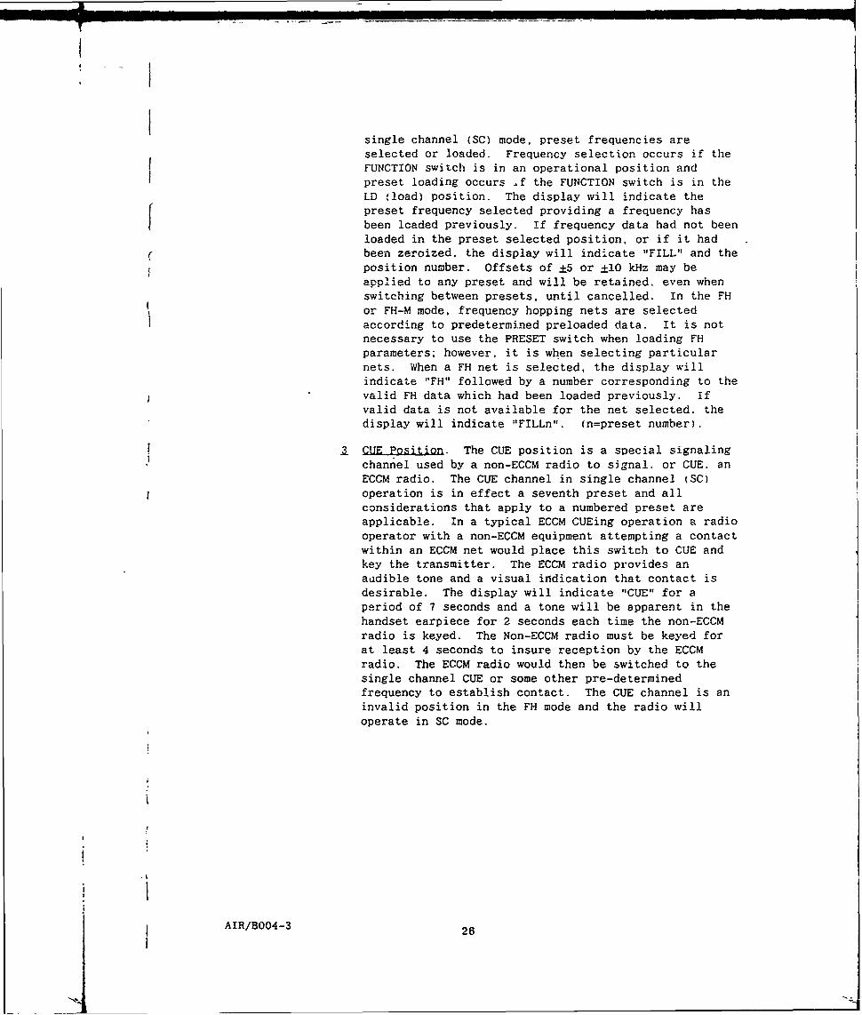
single channel (SC) mode, preset frequencies areselected or loaded. Frequency selection occurs if theFUNCTION switch is in an operational position andpreset loading occurs .f the FUNCTION switch is in theLD fload) position. The display will indicate thepreset frequency selected providing a frequency hasbeen loaded previously. If frequency data had not been
loaded in the preset selected position, or if it hadr been zeroized, the display will indicate "FILL" and the
position number. Offsets of ±5 or ±10 kHz may beapplied to any preset and will be retained, even whenswitching between presets, until cancelled. In the FH
or FH-M mode, frequency hopping nets are selectedaccording to predetermined preloaded data. It is notnecessary to use the PRESET switch when loading FH
parameters; however, it is when selecting particularnets. When a FH net is selected, the display will
indicate "FH" followed by a number corresponding to thevalid FH data which had been loaded previously. ifvalid data is not available for the net selected. the
display will indicate "FILLn". (n=preset number).
CUE Position. The CUE position is a special signaling
channel used by a non-ECCM radio to signal. or CUE. anECCM radio. The CUE channel in single channel (SC)
operation is in effect a seventh preset and allconsiderations that apply to a numbered preset are
applicable. In a typical ECCM CUEing operation a radio
operator with a non-ECCM equipment attempting a contactwithin an ECCM net would place this switch to CUE and
key the transmitter. The ECCM radio provides anaudible tone and a visual indication that contact isdesirable. The display will indicate "CUE" for a
period of 7 seconds and a tone will be apparent in thehandset earpiece for 2 seconds each time the non-ECCM
radio is keyed. The Non-ECCM radio must be keyed forat least 4 seconds to insure reception by the ECCMradio. The ECCM radio would then be switched to the
single channel CUE or some other pre-determined
frequency to establish contact. The CUE channel is aninvalid position in the FH mode and the radio will
operate in SC mode.
AIR/B004-3 26
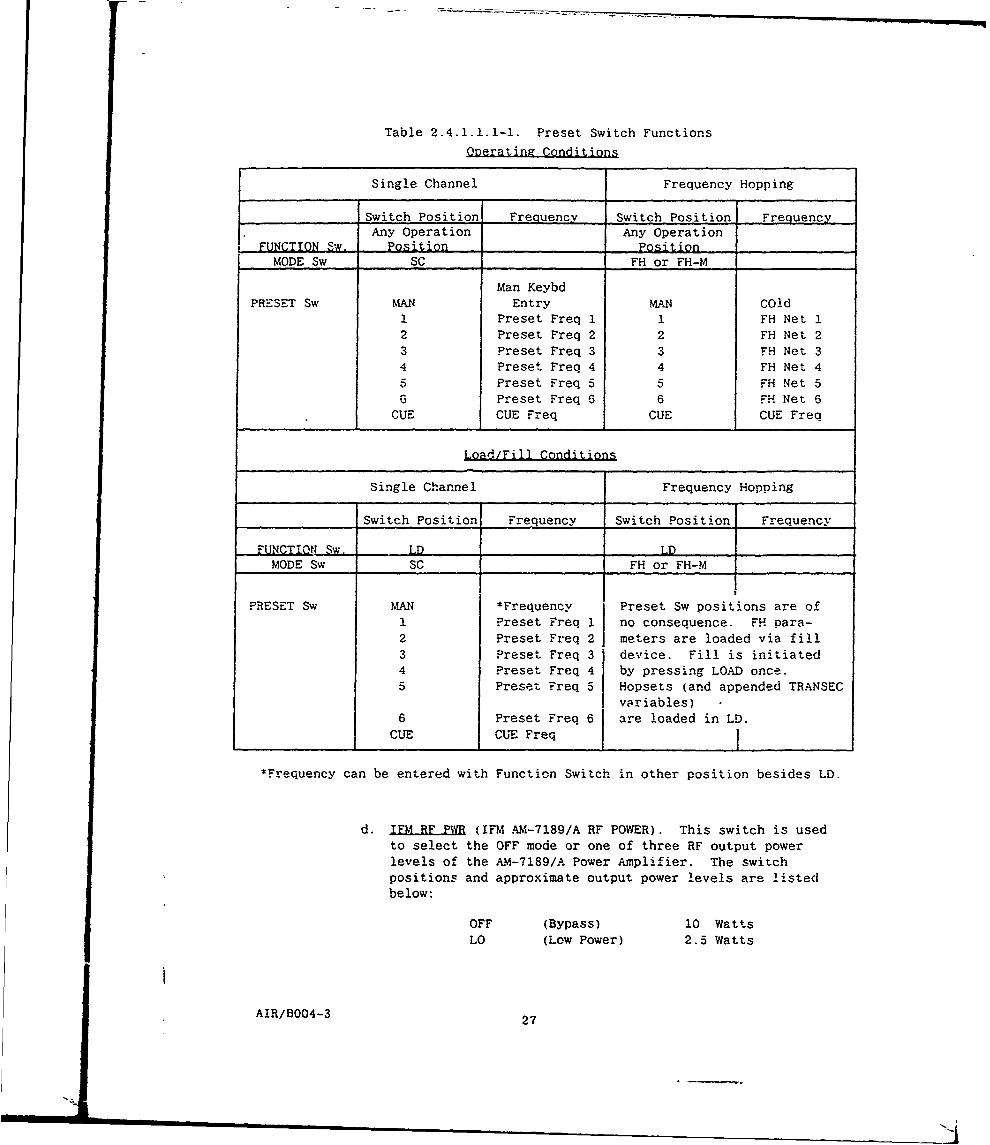
Table 2.4.1.1.1-1. Preset Switch Functions
Ooerating Conditions
Single Channel Frequency Hopping
Switch Position Frequency Switch Position FrequencyAny Operation Any Operation
FUNCTION Sw. Position PositionMODE Sw SC FH or FH-M
Man KeybdPRESET Sw MAN Entry MAN COld
I Preset Freq 1 1 FH Net 12 Preset Freq 2 2 FH Net 23 Preset Freq 3 3 FH Net 34 Preset Freq 4 4 FH Net 4
5 Preset Freq 5 5 FH Met 56 Preset Freq 6 6 7H Net 6
CUE CUE Freq CUE CUE Freq
ad/Fill Conditions
Single Channel Frequency Hopping
_Switch Position Frequency Switch Position Frequency
FUNCTION Sw. LD ._ LDMODE Sw SC ....... _ FH or FH-M {
PRESET Sw MAN *Frequency Preset Sw positions are of1 Preset Freq 1 no consequence. FH para-2 Preset Freq 2 meters are loaded via fill3 Preset Freq 3 device. Fill is initiated4 Preset Freq 4 by pressing LOAD once.5 Preset Freq 5 Hopsets (and appended TRANSEC
variables)6 Preset Freq 6 are loaded in LD.
CUE CUE Freq I
*Frequency can be entered with Function Switch in other position besides LD.
d. IFM RF PWR (IFM AM-7189/A RF POWER). This switch is usedto select the OFF mode or one of three RF output powerlevels of the AM-7189/A Power Amplifier. The switchpositions and approximate output power levels are listedbelow:
OFF (Bypass) 10 Watts
LO (Low Power) 2.5 Watts
AIR/B004-3 27
Jj
NORM (Normal Power) 10 WattsHI (High Power) 40 Watts
The RF output level of the Aircraft RT is constant at 10watts (+40 dBm).
e. VOL C~ntro. The VOL (volume) control is a potentiometerwhich serves to vary the headset receiver volume. The
r volume control is used to adjust receiver volume to acomfortable level consistent with the operator'senvironment.
f. Disnlav. The display is a 5-digit, 7-segment LCDreadout. The capability is provided to vary thebrightness from full sunlight viewability to a low levelcompatible with night vision goggles. The display willbe on continuously and the information presented will bea function of other switch settings or keyboard entries.The display gererallyoperates in conjunction with thekeyboard. However, there are some exceptions. With theFUNCTION switch in an operational mode, the MODE switchin SC, the fzequency stored at a particular location ofthe PRESET switch will be displayed. Changing the PRESETswitch position will automatically cause the newfrequency corresponding to the new switch location to bedisplayed. Frequency or the hopset number is normallyvisible on the display except in certain cases such astime, ERFing, etc. Depression of the FREQ button on thekeyboard will display the current operating frequency orhopset number after such times. As mentioned earlier.the delta frequency offsets (±5 or ±!0 kHz) are operativein either MAN or a numbered preset position of the PRESETswitch. These offsets, once applied, will be displayedas the true operating frequency when FREQ is pressed.Time is also available for display in any operationalmode. Time is indicated in a 24-hour system by days.hours/minutes, and minutes/seconds. CUE will also bedisplayed in an ECCM operational mode. Available alsoare a number of Built-In-Test (BIT) and status wordsindicative of internal conditions within the RT. SeeSection 2.5 "Self Test Description" for details of thesestatus indications.
g. K. The keyboard is a 15-button array of pressureswitches arranged in a 4 x 4 matrix. The keyboard isused to insert or display data, depending on the keyswitch actuated and the positions of the MODE andFUNCTION switches. The keyboard is comprised of 10numerical buttons, three special function buttons, andtwo command buttons. The three special function buttonsare located on the right hand side of the keyboard. Thetwo command buttons (CLR and STO) are located on either
2SAIR/BOO4-3 28

side of the numerical zero button. The special functionbuttons will always initiate a display according to thefunction of the button pressed. Pressing TIME willdisplay time. pressing FREQ will display frequency. etc.Pressing CLR always clears only the displayed data.pressing STO always enters the displayed data into thesystem and is always signaled by a momentary "blink" ofthe display. When the CLR button is pressed, the
( displayed digits (two, four or five dependent upon the
displayed information) will have the numeric replaced bya horizontal line at the bottom of each digi-.. This"underline" feature aids the operator in knowing whereentered data will appear. In the following text. this isreferred to as clearing the display even though the"underlines" appear. A description of the key switchesand their function is presented.
j Switches 1 through 9. Decimal inputs are used to keyin-frequency. load time information, or offsets. Entry
of information is normally digit-by-digit displayedleft to right on the readout. It is to be noted that
operation of the RT is not altered until complete.valid data is registered on the readout and thekeyboard STO button depressed within the 7 sec time out
period. Illegal entries will not register on thedisplay. Incomplete entries will not be accepted whenSTO is pressed. Acceptance of valid data is signaled
* by a momentary "blink" of the display when STO ispressed. At this time. the RT will be caused to actupon this entry. Partial or mistaken data may beerased at any time by pressing CLR. at which time thelast readout will be cleared. Manual frequencies canonly be selected with the FUNCTION switch in anoperational position and the MODE switch in SC. Withthe FUNCTION switch in LD and the MODE switch in SC.new preset frequencies may be entered in conjunctionwith the numbered positions of the PRESET switch. Withthe FUNCTION switch in LD, TIME may be entered oraltered by pressing TIME, then CLR. In all cases,pressing the CLR prior to an entry will clear theaisplay allowing new data to be registered. however.the function of the RT is not altered internally untilSTO is pressed and accepted.
2. CLR. The CLR button is used to zeroize the display.CLR must be pressed to remove the old data "rom thedisplay prior to entering new data during ,D. orchanging frequencies during a manual operation. It canalso be used to clear partial or erroneous entries. Itis to be noted that pressing CLR does not change theoperation of the RT, it only erases the data beingdisplayed on the readouts to underlines appearing in
AIR/B004-3 29

the digit position where a number had been displayed
previously.
S-Q (LOAD). The 0 (zero) switch is used to enter zerosin the same manner as switches 1 through 9 as defined
in paragraph 2.4.1.1.1.g.!. It has a second actionJ(LOAD) which initiates transfer of ECCM parameters.
=TO. The STO button is used to initiate entry of all
data by keyboard entry. In all cases, only valid
complete entries will enable the STO button.
Successful initiation of the entry action will always
be signaled by a "blink" of the display. If the CLR
button is pressed prior to STO. valid data must be
registered before STO will be accepted.
STO has a second function of storing a rec.ived Hopsetor Lockout Set held in holding memory. Selection ofthe preset (1-6) is necessary.
a. FREQ. The FREQ button is used to display the currentoperating frequency during single channel (manual orpreset) operation. It is also used in loading presetfrequencies; however, the FUNCTION switch must be inthe LD (load) position. Whenever the button ispressed, frequency is displayed and an entry sequenceis initiated involving frequency. If the frequenciesstored within the radio (presets and current manual)had been zeroized (Z-A on the FUNCTION switch). then"FILL" and the number of the preset will be displayedwhen FREQ is pressod until new valid frequencies areentered. If the operating frequency currently in usehas been offset, the true operating frequency (plus orminus offset) will be displayed.
In FH, the hopset number is displayed when the FREQbutton is pressed. If a lockout is loaced into the RT.a second press of the FREQ button will display thelockout that is loaded.
ME E. The ERF/OFST (offset) button is used to modify asingle channel operating frequency, manually selectedor preset, to include offsets of ±5 or ±10 kHz. Theoffsets to be applied to the basic frequency aredisplayed by themselves in the two right hand digits ofthe display. The FUNCTION switch can be in anyoperational position, however, the MODE switch must bein SC to apply offsets. Pressing ERF/OFST willimmediately display any current valid offset applied tothe selected single channel frequency. Negativeoffsets are indicated by a negative signal (-)appearing in the center digit position. Positiveoffsets are indicated by no prefix. No offset isI
AIR/B004-3 30
indicated by "00" in the two right hand digits. Toapply an offset, the ERF/OFST button is first pressed.The CLR button must then be pressed. If a negativeoffset is desired, ERF/OFST must be pressed again. Anegative sign will appear in the center digit position.(Repeated pressing of ERF/OFST will alternate betweenplus and minub offsets). The keyboard must now be usedto insert either five or ten. If five is pressed, "05"will automatically appear. If 10 is required, 1 then 0must be pressed. All other buttons will be inactiveand nothing will be registered if accidentally pressed.Once the valid offset is registered on the display.along with a minus or plus (no indication) sign. theSTO button is pressed. The display will momentarilyblink signaling acceptance and initiating frequencyoffset immediately. If the FREQ butto is pressed atthis point, it will display the original operatingfrequency with the offset added or subtracted to it.To'cancel an offset, proceed as before; that is. press
ERF/OFST first to display existing offsets. Then pressCLR followed by 0, which will cause "00" to bedisplayed. When STO is pressed, an offset of "00" isentered returning the operating frequency to itsnon-offset condition.
ERF/OFST has a second function of initiating an ERFtransmission if a Hopset or Lockout Set is in theholding memory and the Mode Switch is in the FH-Mposition.
. IBE. The TIME button on the keyboar"' 4s used todisplay or change the time setting a - ined withineach RT. Time is displayed in three z -.rateindividual fields in days (0 through 99), hours (0through 23), minutes (0 through 59), and seconds (0through 59). Days are displayed in the two left handdigits immediately when TIME is pressed. Pressing TIMEagain will cause the field to change to the two lefthand digits of the second field, minutes in the tworight hand digits. The center digit remains OFF.Pressing TIME the thira time results in the third(minutes/seconds) field being displayed. Minutes aredisplayed in the two left hand digits and seconds aredisplayed on the two right hand digits of the display.The center digit remains off. When TIME i- displayedand CLR has not been pressed, the seconds will berunning. When CLR is pressed, the internal clockcontinues to run, but the display will be static,displaying entry information only. To set or resettime requires that the FUNCTION switch be in the LD
(load) position. The positions of the MODE and PRE- r
1SAIR/BOO4-3 31
switches are of no consequence. With the FUNCTIONswitch in LD, the TIME button is pressed oncedisplaying days in the two left hand digits. Press CLR(clear) and the two digits will be removed. The newdays numbers may then be inserted by keyboard entry.Once the new days numbers have been registered. the STObutton is pressed and the display caused to blinkmomentarily. The new days numbers are now entered andstored. Once the new days have been entered, the TIMEbutton must again be pressed to change to the secondfield (hours and minutes). The previous hours and
minutes are displayed in the two extreme left hand andright hand digits, respectively. CLR is then pressedto remove the oLd hours/minutes display and is replaced
by underlines at the bottom of each digit previously
displaying a number. The new hours and minutes numbers
(four digits) are then entered by keyboard entry. Once
STO is pressed, the display blinks and the new data isregistered. As mentioned before, when the newhours/minutes numbers are registered, the registerednumbers are static and displayed time is not changing.When STO is pressed, time keeping is started, and the
seconds are zeroed prior to the new time keepingprocedure. The third display field (minutes/seconds)is available for display, but cannot be set by keyboardentry. Only when a valid four digit hours/minutesentry has been completed by pressing STO is the oldseconds erased to zero and new time started. This isto accommodate presetting and display of time prior to
a time mark. If an error occurs during any entry
sequence, pressing CLR erases the display and startsthe sequence over. Pressing TIME repeatedly will causethe display fields to rotate as described above.
h. FTI-L. This connector is used to fill ECCM parameters
from an external fill device. Entry of ECCM parametersis initiated by the LOAD button on the keyboard with the
FUNCTION switch in LD. The RT will recognize the
attachment of a fill device and respond accordingly.
2.4.1.2 Dedicated Remote RT. The dedicated remote RT is locatedremotely in the Aircraft equipment bay and operates in conjunction with a
console mounted control head (dedicated remote control unit). Due to theremote location of the RT, the radio's front panel is configured with afill connector (only) as shown in Figure 2.4.1.2-1.
A description of the fill connector given in 2.4.1.1.1h fc;: the panelmounted RT's front panel is applicable to the dedicated remote RT fill
connector.
A detailed description of the ded!- ated remote control unit ispresented in paragraph 2.4.2.
AIR/B004-3 32
IA

*0 0
Figure 2.4,1.2-1. Dedicated Remote RT Unit Front Paniel
AIR/B004-3 33

2.4.1.3 1553B Remote RT. The 1553B remote RT is the basic RT with afront panel configured to interface with the 1553B bus controller. Tuningand control information for the RT is transmitted over a dual redundantserial data bus. The 1553B front panel interface accepts the serial datafor conversion to an RT compatible format. All RT control functionsnecessary for radio operation can be processed via the bus link. Refer to"Multiplex Interface Control Document (MIL-STD-1553)" dated 20 March. 1989and to ITT TP-8144563 for additional information on the RT-1478A.
The front panel interface module contains two PC boards in addition toseparate ±10 volt power supplies. The interface module, shown in Figure2.4.1.3-1, contains four connectors described as follows.
a. Bus A/Bus B - Dual redundant connectors that interfacethe RT to the 1553 bus controller. These Triaxconnectors permit the RT to be controlled by the on-boardaircraft 1553B bus controller.
b. Address. Provides for an A/C-RT address coding. Theassociated address plug is used to assign the RT'sdedicated address. The appropriate pins are grounded inthe plug to establish the address. All other bus trafficwhich does not contain this address is ignored.
c. FILL - Provides an input port to the RT to permitinsertion of fili variables for the ECCM. See paragraph2.4.1.1.1h for a detailed description of the fillconnection function.
2.4.2 Remote Control Unit. The Remota Coz. cl ;nit (RCU). a panelmounted unit, is shown in Figure 2.4.2-1. The front panel is similar tothe panel mounted radio and is within constra.nt; of a three inch panelheight. This unit also contains an 1802 ba.'. microprocessor system withthree LSIs. Two of the L7s are common 'c t.- r'mnd SINCGARS equipmentand one LSI is unique to the ".ircraft SINCQ.dS rvdio. The microprocessorsystem continually monitors '.ht front panel controls. When a control ischanged or a keyboard switch is prestd. serial data is sent to the RT overthe RS-449 interface. When the RT responds with a display message, themicroprocessor interprets this data and sends it to the LCD display.
The RS-449 interface consists of clock +, clock -, data +, data -. anddata direction signals. The data and clock signals are sent over theselines at a 640-Hz rate. Multiple control units may be used by parallelingthese signals. Each control unit (and the panel mounted radio) has atake-control input. This take-control input operates the same as theARC-186 and ARC-164; that is, whenever a control unit's take-control inputline is open, it has control. If the line is grounded, the unit isessentially "off." Because the Aircraft SINCOARS has an electronicdisplay, even when one or more of the control units are not in control, anydisplay information is still presented on all control units simultaneously.
AIR/B004-3 34

ADDRESS
000 FILL (J7)
USA 00O
BUS B
PIL
Figure 2.4.1.3-1. 1553B Remote RT Front Panel
AlR/B004-3 35

PRESETIF~h F PWR
F-2'~ 3 - 7 NORM'H
v CUE eOEH W W7 721 HOM S
F F-FUNCTIONf 4js FH
F SQ ON RXMT jFj=)-
Figure 2.4.2-1. Radio Set C-11466A Front Panel
AIR/B004-3 36
Audio signals are routed, essentially in series, between multipleremote control units from the RT. The volume control of the controllingunit is active. The inactive volume controls do not affect the receivedsignal level.
The front panel switches, keyboard and LCD display are identical withthe front panel description of the panel mounted radio (paragraph 2.4.1.1)and, as such, will not be repeated here.
2.4.3 Signal Data Converter. The Signal Data Converter (SDC)provides the interface of the Intercom, DMD, and TACFIRE Equipment with theAircraft SINCOARS Radio. The SDC provides the appropriate control signalsto allow for various plain text and cypher text modes of operation. Itprovides for conversion of FSK analog data to 16 Kbps digital data intransmit modes. In receive modes, the SDC provides for conversion of 16Kbps digital data to FSK tones; 7 out of 13 error correction is alsoprovided. An analog voice mode to and from the aircraft intercom is alsoprocessed by the SDC.
The SDC is designed to interface future aircraft data devices
operating et variable data rates through the addition of a rear panelswitch. Data devices transmitting/receiving at bit rates of 600, 1200.2400, 4800, and 16000 bps will be converted to the required SINCGARS RTdata format in the RT transmit mode and recovered from the same data formatin the RT receive operation.
The Signal Data Converter is shown in Figure 2.4.3-1.. It has abacklit NVG Generation III ANVIS compatible panel with an Audio/Fillconnector, a volume potentiometer, two switches and a compartment to hold af Hold--Up Battery (HUB). The switches are described as follows:
I MODE Switch - The SDC provides for control of the RT toestablish the correct operating mode. digital oranalog, in both receive and transmit modes. It is usedto select Plain Text (PT), Cipher Text (CT). Time Delay(TD), and Remote Variable (RV) modes as well as OFF,TEST, and LD.- The LD position is used when loadingCOMSEC variables. TEST is used to perform
Built-In-Test (BIT) on the unit. The OFF positionpowers down the unit with the exception of memorycircuits which are kept active by the HUB. Note thatthe PT and TEST positions are "pull-to-turn" positions.
Z VARiable Switch - This switch is used to select theappropriate variable 1-6. Position 7 "Z" is a"pull-to-turn" position which is used to zero COMSECvariables in all 6 presets.
CT VOL Control - The CT VOL (volume) control is a
potentiometer which is used to vary the Cipher Text(CT) receive audio volume to a comfortable levelconsistent with the operator's environment.
AIR/B004-3 37

MODE VAR @TD RVLD 4 560
RMT/CT TESTz
AIR/B0000
1I/O0 - 38
4 .... .....

A Fill A/D Connector - This connector is used to attach aKYK-13 or similar approved Fill Device to the SDC toload the COMSEC variables. It also provides the Audioand digital interface to handsets and digital deviceswithout the use of the intercom.
2.4.4 SDC Rear Panel Switches. The rear panel of the Signal DataConverter contains two switches: a data RATE switch and an "*" switch.The data RATE switch is a rotary switch which allows selection of datarates from 600 to 4800 bps to be interleaved to 16 kbps. The option forAD! and TF (AD2) are also contained on the data rate switch. The "*"switch is also located on the rear panel of the SDC. The switch is anon/off switch but due to the classified nature of the function it will notbe discussed in this document. The correct position for testing will beincluded in the testing section of this document.
2.5 Self Test Description. To determine operation of the ECCM moduleand to test operation of the Aircraft Radio Subsystem (ECCM installed).proceed as follows:
I FUNCTION Switch - Test
. MODE Switch - Any position may be set beforeI PRESET Switch - Any position or after FUNCTION
switch is turnedto TEST
- RF Pwr - As required- VOL - As required
No keyboard entry is required. The display will show 5dashes for approximately one second (as shown in step4).
No keyboard entry is required. The display indicates"E" if ECCM is present (a dash in the same position ifabsent). In any case, the display is on for 3 secondsbefore progressing to automatic test steps. This is toallow time for an operator to move the switch to otherpositions if a complete test sequence is not desired.
fi After 3 seconds the display automatically changes to:
AIR/B004-3 39

This will test the operation of all segments of alldigits of the display. The display will remain on for3 seconds and extinguish with the RT progressing to the
next automatic test step.
2 In the next auto test steps the operation of the RT.
the Data Module, and the ECCM are verified (in this
order). All tests are under microprocessor control andrequire no additional operator action. Successfulcompletion of all tests will be indicated by:
G 0 0 DI
"Good" will remain on for 5 seconds and extinguish.The RT will then be left in the receive mode asidicaLed by the K&YBOARD, MODE, or PRESET switches.Transmitter keying is inhibited. Tests may be repeatedby moving the FUNCTION switch out of the TEST positionand back again.
- Failures in the automatic tests will be indicated by
the word FAIL followed by a number to indicate thefailed component.
The control panel tests its own internal circuitry andthe interface to the RT before commanding the RT test.
IF I Al I FTF7 Indicates failures of the inter-face to the RT
IF I AlI Li 8 1 Indicates internal failure ofi IL the control panel
F FI AFI Indicates failure of the RTW FT11 RF receive path
IF I A1 I I L oduIndicates failure of the ECCM
module
When a failure occurs, the display is immediately
presented for 3 seconds. After 3 seconds (plus a .5second delay). the 3 tests are caused to continue. Thetests will be continually repeated until terminated by
AIR/B004-3 40

changing the FUNCTION switch position. If severaltests are failed, the display will alternately presentthe results at each failed component.
NOTE: Some specific tests are performed in anyoperational position on a continuous basis with theresults of this test either audible or visible. Thesetests are not specifically associated with the TESTportion of the FUNCTION switch.
VSWR Test: This test is performed each time thetransmitter is keyed and during the transmission. if
VSWR exceeds 5:1, the audio sidetone will be inhibited.
i0 ECCM: When the PRESET switch position is changed whileoperating in a frequency hopping mode, the fill data isexamined and either "FXXX" if a valid hopset has beenloaded or "FILLN" if no hopset will be displayed. BITis also run on .the non-volatile R.AM in the ZA switchposition. If FH or FH-M is selected without an ECCMmodule present, "Error" will be displayed.
j11 SDC Built-In-Test (BIT): The SDC includes aBuilt-In-Test (BIT) function. The test function occursautomatically during power up and whenever the unit isplaced in 'TEST' mode. Three beeps shall be given ifthe SDC passes BIT, and in case of failure, a 500 Hztone shall be output to the intercom and Fill AiDconnector. The 500 Hz tone shall be continuous untilthe operator sends a PTT signal, at which time the unit
shall return to operational mode with the fault.
4K
AIR/B004-3 4

3.0 REQUIREMENTS
f 3.1 General.
3.±. Ac w&. Any installation of the AN/ARC-201AiV) subsystem.which is in accordance with MIL-I-8700 and the requirements of thisspecification, shall be considered acceptable. Such acceptance, however.does not constitute safety of-flight approval.
3.1.2 Responsibility for Miscellaneous Components. The contractorshall furnish and install all required plugs, cables, connectors, junctionboxes. terminal boards, circuit breakers, switches, relays, wiring.mounting hardware, RF filters. impedance matching ne.vorks, andmiscellaneous items to complete satisfactory installation and operation ofthe AN/ARC-201A(V) aircraft subsystem. All contractor furnished electronic
equipment shall be in accordance with the applicable electromagneticinterference and compatibility requirements in ML-STD-461 and the
requirements in MIL-E-5400 for Class IA equipment designed for operation inboth fixed wing aircraft and helicopters.
examinations and tests specified in Section 4 to ensure compliance with theapolicable requirements of Section 3.
3.1.4 Reports. The contractor shall prepare and submit to theprocuring activity all reports and other supplementary data as specxfied bythe contracting officer.
3.1.5 Radio Freouencv Assignmert. If required, the contractor shallrequest from the procuring activity a radio frequency assignment for which
he has no assignment and is otherwise necessary to verify that theAN/'ARC-201A(V) performance is in accordance with the requirements specifiedherein. Receipt of radio frequency assignments from the procuring activitydoes not relieve the zontractor of any responsibility for obtaining aFederal Communications license to operate equipment radiatingelectromagnetic energy.
3.1.6 Check-off List. The contractor shall record the results of theapplicable examinations and tests specified in Section 4 on a check-offlist similar to that shown in Figure 3.1.6-1. The contractor shall preparea check-off list for each AN/ARC-201A(V) installed in an aircraft andmaintain a file of these records for reference. as necessary. by theprocuring activity.
3.1.7 Eguipment Non-Complianc. Except as specified in paragraph3.1.8. if the equipment fails to comply with the requirements of paragraph4.4, the requirements and procedures specified in MIL-I-8700 shall governwith the exception that replacement of component parts shall be made onlyupon specific written approval by the procuring activity. The applicable"Quality Deficiency Report" shall be utilized when reporting equipmentfailure. Shipping instructions for the faulty equipment and distribution
requirements for the equipment failure repori shall be specified by thecontracting officer.
AIR/B004-3 42

-- I
'-44
C)
C6
0
0. a
1-4 4-' 00 U3- c4 c3- U).. 0 4 (
ca --
0N
0 m o10L" Dt
o tm
o- -4 0 4 1- -
zp - U)S U) 0) o0 t Ct )c - 4-4a4 ) OCV) CV v )
E -+ N N N N N N
.- IC 0 0.) Um to0) O-- --q K ~ toV o
r,- 0 *-4f 0 r- Q)> a) to .- v m 0n 1.m
S"4 0) -- - - -- - - -
U00 ) ~ - 0 L0)10 U131 W *.0,in 0 w0cE W a 0- - t- t- I- t- 0 to t- 0 -- t.- D l -0 .0 0 -0) 06 -. :$ 0& -a) " ,cm " t- 0) CD 00 0 c) o -4 .zCD
: ~ ~~~t a) o a 0 . . . . .- . 0 n €.,,-. 14 ZD -4 . z o o t- cm- to- m - t -, - r-- .i- . .0- to- - I
o) En. ) ", v L•O - to 0 N m V. vI -) c co -
0 < O.0 0U4- 0.0 -- 0O C "' O U O OC0 0.- - 0))' . .O ,
-4U) C3 ) a) .to)
_1 .< .-4JC 0 I0 D
4) a) m. j d0 .,a 3 ) a ) ,-
I-U %) a) C6 ) .
4-) :5
0) d).00.0.-0.0 -
.C-0 0 0- a) O:
.0 . -4 > ,
-44 114 C ) f. 4.'=
-4O 4O ) 4' ) a ),a
a.O c ,-- e aa0.0 0 ) $4 0-
4t3AIR ( ICOM) B004-3
N~zo

-!4
E- 074
- m 0 t- t- t-. .
M n v - m
:n
U4 ::3 a)
S N E a E E a a E
00
Z 0. Y
N C - -4 1
- - - -4 -- ZZ - 0 ,-. V, 0
U))', i
444
T0 T0) 0F- 0
-- I 4j0
a)) >1 0)>.
4- bo -4 E
.0 0 0)- -9 11) aUas
U,;4i o a
C L -'o ca -. l
o a, -~-3 , .44ATR(Trtq)'nO
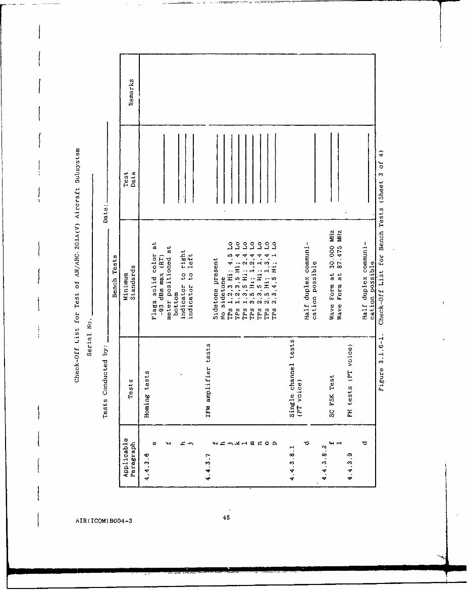
I
t~
52os i !
4-)0 i0
> 0
.0 4- CO l
U0 a)-Cc
4-'(44
cz)
5-4 .0
p 0 a
0 0 00 0 co 0 0 Io5o4' 04-' W 40(-'0 - 0(4- 4r. - toH- 2 (n 2 0
r-CS) 0 0 0 04 *-4 S-4 0M a'U 0 4-
0 0 o 0 - - - - - - 0L0 0
to W 4J C. 0 1- - o
Cc 0C 014) 4.J- >0~1~--U >U 4j
0 z H~~
ti 0
Iz
4-4..J- d)C3~UI)Uuc 00 -1~
AI) (ICOM) 0B004---4
0
0C.)
-4-4
U) 4- to (0 b4J- T) 0) 0)
0 4-) 0o U)0) -1
0- >- 0
4 X ) 0)4C44 0- 14- 0 4 -4.0 a - 4-' CN0
4 co C-00) 0 )
0 4 cis ) 40 (4 U
C6 0 -0.(-.4
AIR(ICQM)B004-3 4

a) v4-'1
>) 0
Cl)
4-4-
4-))
CV)
C)N N N N t-1 N N N -
U) d).0 U) 4)) .OU) utLf ) .4mL
-441 O t- t-t- t-O0 - t- U, --4 -4 C:1-4 o 00 )c' C) a t-0) r4 .0 j 4-'0.I o 4-) .04 0M c zco
I> 0 t- V) 0 C t- .,> 4o 4- 4)m v t 00 Cd0 .) U) (n 41)V 4
4J V) U) < 4 0ul w) a)~@@ I 0 d4 0 4,
U) -4 t- ) l + 4.)H E-4 0 C: : _ : C ac 0 cr Cd0) ~ 4 4..
a Q4C 0 00 00 0 00 C')-.4 0 0 0) -4 C:) C)Z0 cd 4)1 *j- - , 4 , d .4 .- 4 -4 '4 ) 0 U) *-4
0 (z cd es Cd -d 03 '- cs Cc)4 Cs as"
4 04 od e) L) C) C) C)C C ) 00 x C) C) C) d.)) -)U) +,.) -,4 .. -4 -4.-4 -4 .. 4., - 4 ) ..4 . z 4-'
U) $4 M000 0 r.0 bO 4) rz C) 0 ) bD czH4 + z C:> 11 4 0>
E! E2 S22 E E S e-. E 04) 2--'0- 000 00 00 0* 0 0 0C 0--'-,. C
c~ 0 0 0 0 '44 0 0 U) ~cO U) .0440 0-Pz
4-' -
-- 4U -4
0 4$ C) co0) E-4 4) 441) 00 c)-
41 -- 4 0U)~~ '44 4
41 Cd (1' Cd 4)0
V)40
U) 41 5)4-
-4 >0 0 0
-4f X-4 0z 4 4 0 0
$4 4)$4 -- U
44.4 a.~ 4 *-
446AIR(ICOM) 0-

3.1.8 Equipment Under Warranty. The equipment repair procedures
specified in MIL-I-8700 are not authorized for Government furnishedequipment which is under warranty by the equipment manufacturer
Disposition and reporting of faulty equipment shall be as specified in
paragraph 3.1.7.
3.1.9 Promiring Activity Approval. In all cases where approval by
the procuring activity is specified, the contractor shall be in receipt of
said approval prior to conducting any tests, inspections, or otherwise
utilizing the proposed equipment or procedures.
3.1.10 Test Eauipment Calibration. The contractor shall prepare a
statement which identifies the test equipment utilized in the performanceof the tests specified in Section 4. The statement shall include
certification of the test equipment calibration in accordance withMIL-C-45662 and be forwarded to the procuring activity as supplementary
data to the applicable test report.
3.1 11 Electronic Sdbsvstem Ce,-tifi.a.tin. The contractor shall
prepare a statement vhich certifics that all aircraft installed electronicsubsystems which are utilized in the performance of the tests specified in
Section 4 are in accordance with the applicable specifications. Thestatement shall be forwarded to the procuring activity as supplementary
data to the applicable test reports.
3.1.12 Instrumentation. The instrumentation system application andtechniques utilized to collect the engineering flight test data shall be
fully disclosed and fcrwarded to the procuring activity as supplementary
data to the applicable test report. The range and accuracy (includingtransducer and printout errors) of each recorded signal shall be adequatefor comprehensive evaluation of the parameter(s) being measured. The
* supplementary data shall include but not be limited to the following:
a. Recording media (block diagram including component
identification numbers)
b. Transducer and/or signal source parameters.
c. Signal conditioning for each signal (schematic).
d. Preflight and post-flight calibration techniques.
e. Calibration test equipment list with calibrationcertification.
f. instrumentation system range and accuiacy certification
for each recorded signal.
g. Calibration curves necessary for complete analysis of
each recorded signal.
h. Other data required.
3.1.13 Electromagnetic Comnatibility. Electromagnetic compatibilityand test plans shall be prepared by the contractor in accordance with
MIL-STD-6051 and submitted to the prucuring activity for approval.
AIR/B004-3 47

The contractor shall install the AN/ARC-201A(V) in accordance with theelectromagnetic compatibility control and test requirements specified inthe contract.
The AN/ARC-201A(V) Aircraft subsystem EMI characteristics are listedin Section 3.2.12. An EMI test report shall be forwarded to the procuringactivity as directed by the contracting officer.
3.1.13.1 Critical Frequencies. There ara a number of frequencies{ considered critical to the operation of the AN/ARC-201A(V) subsystem which
may require special consideration during Electromagnetic compatibilitytesting. These frequ'encies are generated directly within the equipment asclocks or are the result of multiplication, division, filtering, mixing, orotherwise handling of the digital and analog signals within the equipment.Following is a list of these frequencies. Although specific operatingfrequencies only are listed, any of the harmonics and subharmonics as wellas mixing products in particular combinations should be investigated ifproblems involving pickup, radiation, and inuerference occur during EMCtests.
640 Hz Data transfer for remote control
16 kHz Data rate for communication
20 kHz ECCM data rate
40 kHz Data transfer from front panel to display
120 kHz SDC power supply switching rate
160 kHz RT power supply switching rate
240 kHz Front panel timing pulse rate. SDC Power Supplysync pulse.
320 kHz Clock for data and tuner control and antenna tune
640 kHz Microprocessor clock, SDC COMSEC Module Clock
1.92 MHz Clocks in SDC, RCU and front panel
2.133 MHz ECCM clock
3.2 MHz Synthesizer clock and RT-1478A clock
3.9 MHz Power amplifier clock
16 MHz Data clock in RT-1478A
In addition, the IF frequency is 12.5 MHz with the local oscillator
(LO) above the tune frequency. Any RF spaced 12.5 MHz from the LO mightcause receive signal degradation.
4SAIR/B004-3 48

3.1.14; Equipment Components. A brief description of theAN/ARC-201A(V) Aircraft system and its capability is included in sections2.4 and 2.5 of this specification. The components of the Aircraftsubsystem AN/ARC-201AV) to be tested are listed in Table 3.1.14-1.
Table 3.1.14-1. Equipment to Be Tested for AN/ARC-201A(V) AircraftSystem
Wgt. Per Maximum UnitPart Number Unit Power Consumption
Equipment Designation or Nomenclature (pounds) at 27.5 Vdc Remarks
Panel Mounted RT RT-1476A/ARC-201A 9.0 22W(R) 105W(T)Dedicated Remote RT RT-1477A/ARC-201A 10.0 22W(R) 105W(T)Remote Control Unit C-11466A/ARC-201A 4.0 1.4W Can alsofor RT-147?A/ARC-20IA be used
withRT-1476A
MIL-STD-1553B RT RT-147SA/ARC-201A 10.0 25W(R) 107W(T)Mounting Base MT-6363/ARC-201 2.5 N/AHard Mount MT-6374/ARC-201 2.5 N/ASignal Data Converter CV-4122(C)/ARC-201A 6.5 20WSDC Hard Mount MT-6709/ARC-201A 2.8 N/ASDC Adapter Tray 'MT-6710/ARC-201A 2.5 N/A
3.1.15 Additional EQuioment Reguired. In addition to the equipmentlisted in Table III, the equipment listed below is required for the variousconfigurations of the aircraft subsystems (AN/ARC-201A).
For Panel Mounted RT (RT-1476A)
Depending upon desired mission and operational configuration, thefollowing auxiliary equipment may be interfaced with the panel mounted RT.
* Remote control unit (C-11466A)* Power amplifier IFM (AM-7189A)* Two homing antennas
* Communication antenna* COMSEC VINSON (KY-58)
* COMSEC applique Z-AHQ* Data rate adapter (CV-3885)" Homing indicator (ID-1351A)* COMSEC remote control (Z-AI:P)* A/C intercom sets (C-6533, C-10414, C-1611)* A/C headset (H-157/AIC or H-101/AIC)* Digital message device (AN/PSO-2), TACFIRE* Take control switch (Aircraft cozkpit mounted)" Airborne Target Handoff System tATHS)* Signal Data Converter (CV-4122)
AIR/BO04-3 49
For Dedicated Remote FIT (RT-1472A)
Depending upon mission and operational configuration, the followingIauxiliary equipment may be interfaced with the dedicated RT.
* Power amplifier IFM (AM-7189A)I * Two homing antennas0 Communication antennas0 Homing indicator (ID-1351A)f * Data rate adapter (CV-3885)* COMSEC VINSON (KY-58),0 COMSEC applique Z-AHQ0 COMSEC remote control Z-AHP* A/C intercom (C-6533, 010414, 0-1611)* A/C headset (H-157/AIC or H4-l0l/AIC)* Take control switch* Airborne Target Handoff System (ATHS)
* Digital message device (AN/PSG-2), TACFIRE0Hard Mount MT-6374/ARC-201
0Mounting Base MT-3664/ARC-131
0Signal Data Converter (CV-4122)
0Adapter Tray (SDC) (MT-6710)0Hard Mount (SDC) (MT-6709)
For 1553B RT (RT-1478A)
Tefollowing auxiliary equipment may be interfaced with the 1553B FITas required by mission:
* Power amplifier IFM (AM-7189A)a Two homing antennas* Communication antennas* Data rate adapter (CV-3885)* Homing indicator (ID-1351A)
* COMSEC VINSON (KY-58)0 COMSEC applique Z-AHQ
0 COMSEC remote control Z-AHP0 A/C intercom (C-6533, 0-10414, C-1611)
* A/C headset (H-157/AIC or H-101/AIC)
* Digital message device (AN/PSG-2), TACFIRE0 Hard mount MT-6374/ARC-201* Airborne Target Handoff System (ATHS)
* Integrated Control/Display System
3.1.16- Seqigmnal Dat Converter (CV-4122)
0 Had Munt(SDC) (MT-6709)
3.1.1 TestEnuinment Required. The test equipment in Table3.1-6-1or quimen ofequal or superior characteristics, shall be used
cnsideerdrmuniqe tof the tests specified herein. Items which areconsderd uiqu totheequipment under test and which may be loaned to
the contractor by the procuring activity are marked with an asterisk.
AIR/B004-3 50
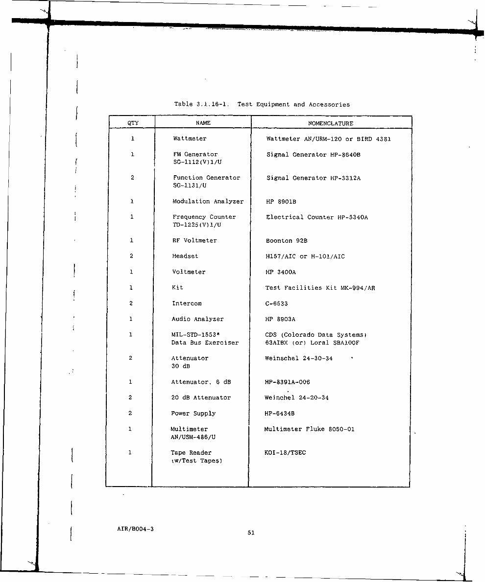
Table 3.1.16-1. Test Equipment and Accessories
QTY NAME NOMENCLATURE
1 Wattmeter Wattmeter AN/URM-120 or BIRD 4381
1 FM Generator Signal Generator HP-8640B( SG--1112 (V) 1/U
2 Function Generator Signal Generator HP-3312ASG-113 1/U
1 modulation Analyzer HP 8901B
1 Frequency Counter Electrical Counter HP-5340ATD-1225 (V) 1/U
1 RF Voltmeter Boonton 92B
2 Headset H157/AIC or H-l0l/AIC
1 Voltmeter HP 3400A
1 Kit Test Facilities Kit MK-994/AR
2 Intercom C-6533
1 Audio Analyzer HP 8903A
1 MIL-STD-1553* CDS (Colorado Data Systems)Data Bus Exerciser 63AIBX (or) Loral SBAlOOF
2 Attenuator Weinschel 24-30-34
30 dB
1 Attenuator. 6 dB HP-8391A-006
2 20 dB Attenuator Weinchel 24-20-34
2 Power Supply HP-6434B
1 Multimeter Multimeter Fluke 8050-01AN/USM-486/U
1 Tape Reader KOI-18/TSEC
(w/Test Tapes)
fAIR/B004-3 51

Other items may be supplied in special circumstances, but in all cases suchcircumstances must be justified by the contractor and approved by thej procuring activity.
3.2 Installation. All government furnished electronic equipment andcontractor furnished electronic equipment shall be installed in accordancewith MIL-I-8700 and as specified herein.
3.2.1 Cie •al. All electrical wiring required for installation ofAN/ARC-201A(V) Aircraft system shall be in accordance with MIL-W-5088 andas specified herein. Refer to Figures 17 through 23.
a. Avoid sharp bends in all cables where possible.
b. Avoid running any cables carrying signals in the sameducts carrying rf power and aircraft power: in particular115 volts, 400 Hz.
c. Extreme care must be taken to prevent entrance ofnon-contained fuel, oil, or other foreign substances intothe compartments in which the equipment is installed.
d. Do not disconnect or connect any connector to remove orreplace any component when power is applied to theequipment.
e. Cable lengths and plug requirements are determined byparticular installation. Cables and'connectors are notsupplied with the equipment. Use RG-214/U, RGl42B/U orRG236/U cable. Cable loss shall not exceed 0.5 dB.Total cable length for the RF path shall not exceed 50feet. Note - 50 feet at 0.5 dB maximum %ould require useof RG236/U cable. (Total cable length in inches.including connector lengths, shall be determined in orderthat a zero calibration cable can be fabricated for usein bench checks.)
f. When fabricating RF cables, use extreme care to avoidintroducing a high voltage-standing-wave ratio. The RFcables are used to interconnect the receiver-transmitterand the antennas. Each coaxial cable shall be checkedaccording to paragraph 3.2.6.1 prior to installation inthe aircraft. Every effort should be used to minimizebreaks in the RF cables. All bulkhead breaks in RFcables shall be safety wired in accordance withMIL-W-5088.
3.2.2 Electrical Bonding. Electrical bonding shall be in accordancewith MIL-B-5087 and as specified herein. Refinishing of bonded surfacesshall be in accordance with the applicable requirements of MIL-F-14072.
3.2.3 A. Installation, design, and location of aircraftantennas shall be in accordance with MIL-STD-377 and as specified herein.
AIR/BO04-3t I52
__ _ __ _ _
3.2.4 Control Panels. All contractor furnished rack or consolemounted control panels shall be in accordance with MIL-C-6781 and asspecified herein.
3.2.5 Mountings. All contractor furnished cases, mounting bases andvibration mounts shall be in accordance with MIL-C-172 except that the
transmissibility in each of the three mutually perpendicular principal axesof the mounting base shall not exceed three (3) g's.
3.2.6 Precautions.
3.2.6.1 Voltage-Standing-Wave Ratio (VSWR) and Continuity Checks.Before connecting the cables to the equipment, conduct the followingchecks:
a. Check the interconnecting coaxial cables for VSWR using asingle-channel insertion loss test set having an RF generator. standing-wave bridge, indicator, and a suitable 50-ohm resistive termination. TheRF generator shall be able to provide an output frequency of 88 MHz. TheVSVR at 88 MHz shall be 1.2:1 or less. Total loss in the cables shall not
exceed 0.5 dB. Total leakage between cables shall not exceed -90 dB. Dcelectrical continuity between inner conductors shall be verified.
3.2.7 Power SupPly Reauirements
a. The aircraft RT units and SDC shall operate under allenvironmental conditions over the supply voltage range of24 to 29 Vdc and a nominal voltage at 27.5 Vdc.
b. For a supply voltage of 21 Vdc, the aircraft RT shallbe capable of delivering a minimum of 4 watts of RFpower to a 50 ohm load and in addition there shall be no
degradation to receiver performance.
c. For supply voltages of 17 Vdc and 30 Vdc, circuit damageto the RT units and SDC shall not occur in thiscondition; further, reverse voltage and transientprotection shall be provided as defined in MIL-STD-704.category B.
3.2.8 Normal Duty Cycle. For purposes of this specification. normalduty cycle is one minute transmit, five minutes receive.
3.2.9 Environmental Requirements. The AN/ARC-201A(V) complies withthe environmental requirements specified below and shall be installed to
operate within these limits.
Temperature-Altitude MIL-E-5400/Class 1AHumidity MIL-STD-810D Procedure II.
Cycle 4Shock (g's; duration) MIL-STD-810CVibration: As specified in applicable
Product SpecificationCDRL 3170B005
AIR/B004-3 53
N'.

Rain 2 inches per hour on frontpanels of the normally
mounted RT remote control
unit and SDCFungus MIL-STD-810CSand and Dust MIL-STD-810CSalt Atmosphere MIL-STD-810CNuclear Survivability (Refer to Sections 2.2.2 and
2.2.2.1)
3.2.10 Pressurization. - (none required)
3.2.11 Coling. - (none required)
3.2.12 Electromagnetic interference (EMI) Characteristics. TheAircraft SINCGARS equipment shall be designed to comply with the emissionand susceptibility requirements of MIL-STD-46!, when tested with themethods, procedures. and requirements of MIL-STD-462. listed below:
CEO (c) CSOl (e) RE02 RS02
CE02 CS02 (f) RS03CE03 CS03 Ra03.1
(a) CE05 (d) CS04(b) CE06 CS06
a. 20 dB relaxation from * ' MHz to 10 MHz.
b. Spurious emissions shall be -100 dB relative to thefundamental frequency power level, except (5) emissionsshall be permitted to be -87 dB. Harmonic emissionsshall be per MIL-STD-461, except that the harmonics the3rd shall be z 60 dBc and harmonics > 3rd will be Z 80dBc. Local Oscillator harmonics shall be below thelimits of MIL-STD-461 except for a maximum of threeharmonics which shall be 15 eB above the MIL-STD-461limits, for the homing antennas.
c. Specification limits are reduced from the MIL-STD-461levels to those of MIL-STD-704 which specifies a maximumripple voltage of 1.5 volts peak or 1.0 volts RMS.
d. CS04 testing procedure in Single Channel Analog Modeshall consist of adjusting the desired RF signal level 5dB above that required to obtain a SINAD reading of 10dB. Failure criteria shall consist of degradation belowthe 10 dB SINAl level. CS04 testing procedure in SingleChannel Homing mode shall consist of adjusting thedesired RF level to a level 5 dB above that at which theSignal Adequacy circuits change state. The undesiredsignal level shall be adjusted to a level 80 dB above thelevel determined in the Single Channel Analog test whichproduced a SINAD reading of 10 dB. In the event that aresponse is detected (the Homing Steering indicator
AIR/B004-3 54

deviates more than ±I division), the desired signal levelshall be adjusted to a -60 dBm level, and the frequencyof the response shall be recorded. Failure criteria
shall consist of response > ±1 division at this increaseddesired signal level.
e. RE02: Narrowband and broadband emissions shall bedefined by Figures 2 and 3, except for emissions of thefundamental and its harmonics. The fundamental is exemptf and the harmonics shall not exceed limits by more than 10dB except for three harmonics which shall not exceed thelimits by more than 20 dB. In Transmit moaes. theharmonics of the operating frequency of the switchingpower supply -1.0 MHz shall not exceed the limits by morethan 15 dB.
f. The on-channel signal in all modes shall be incr-asec -80 dBm when the RS03 source signals 'radiated energytfall on harmonics of the local oscila.tor plus or minusthe IF (intermediate frequency), including the T7 iFself
A maximum of 5 frecuencies are to be allowtd whichrequire an on-channel signal of -70 aBm tc maintain '- IBSINAD.
3.2.13 Location Considerations. Every consideratr_.n shaK: be given
the location of equipment and in the design of installati,- Iptaiis topromote operator efficiency and ease of adjustment and rep.iacement. Theseconsiderations shall not be compromised to facilitate aircr 't productiontechniques. It is especially important that the RT be loci- d andpositioned so that access to the FILL connector is maintain- Dr access can
be made easily available when required. Refer to appendix E -r additionalinformation regarding connections to the FILL connector
3 2.14 Detailed Reguirements.
3.2.14.1 Panel Mounted Receiver-Transmitter, RT-1476A. The PanelMounted RT is designed to replace the ARC-114. It is controlled by ;ts ownlocal control front panel but may be remotely controlled by the C-11466ARemote control Unit.
3.2.14.2 Dedicated Remote Receiver-Transmitter RT-1477A and Remote
Control Unit- C-11466A. The dedicated remote RT and the RCUform a remote control Aircraft radio system. The primary use of this radiois as a replacement for the ARC-131 and it may be mounted on either the
ARC-131 adapter tray, MT-6373 or the hard mount, MT-6374.
3.2.14.3 MIL-STD-1553B Receiver-Transmitter. RT-1478A. TheMIL-STD-1553B RT is intended for new installations such as the ArmyHelicopter Improvement Program (AHIP) which features the MIL-STD-1553B bus.It is intended to be hard mounted on the MT-6374.
3.2.14.4 Remote Control Unit. C-11466A. The RCU is always used withthe RT-1477A dedicated remote RT and can be used with the RT-1476A panel
AIR/B004-3 55

mount RT. It is configured to the panel mount in an aircraft cockpit Its
front panel is similar to the front panel of the RT-1476A.
3.2.14.5 Signal Data Converter. The SDC can be either panel mounted
in the helicopter cockpit or mounted on the SDC Hardmount. MT-6709 in new
ir.qtallations or mounted via the SDC Adapter Txay, MT-6710 to the KY-28mount (MT-3802) to use existing aircraft wiring in present installations,
AIR/B004-3 5
Li
4.0 QUALITY ASSURANCE PROVISIONS
4.1 Responsibility for Inspection. Unless otherwise specified in the
contract or purchase order, the contractor is responsible or the
performance of all inspection requirements as specified herein. Except as
otherwise specified, the contractor may utilize his own facilities or any
commercial laboratory acceptable to the Government. The Government
reserves the right to perform any of the inspections set forth in the
specifica'-ion where such inspections are deemed necessary to assure
supplies and services conform to prescribed requirements.
4.2 Classification of Inspections. The inspections required to
ensure conformance with the requirements of this specification are
classified as follows:
a. Installation examination (see 4.3)
b. Bench tests (see 4.4)
c. Preflight tests (see 4.5)
d. Flight tests (see 4.6)
4.3 installation Examination. The AN/ARC-201A(V) and all associated
equipment which is installed by the contractor shall be examined to
determine compliance with section 3.
4.3.1 Installation Drawings. Installation drawings for the various
radio configurations and auxiliary items for the AN/ARC-201A(Vi Aircraft
system are covered by Figures 4.3.1-1 through 4.3.1-10. Configurations
shown are (1) Panel Mounted radio RT-1476A, (2) Dedicated Remote Radio
RT-1477A, (3) 1553B Bus Controlled Radio RT-1478A, (4) Remote Control Unit
C-11466A. (5) Data Rate Adapter (Panel Mount), (6) Hard Mount MT-6374 with
an RT-1477A, (7) Hard Mount MT-6374 with an RT-1478A. and (8) Adapter Tray
MT-6373 with an RT-1477A. (9) Signal Data Converter on MT-6709 Hard Mount.
(10) Signal Data Converter on MT-6710 Adapter Tray. The installation
drawings include outline dimensions. location and identity of controls.weight, location, identity and part numbers of interface connectors.
location and size of mounting holes and other pertinent information.
4.3.2 External Wiring Digrams. The interconnections for six basic
radio configurations and the peripheral, auxiliary equipment and/or
commonly used optional equipment are shown on Figures 4.3.2-1 through
4.3.2-6. Some of the peripherals shown are part of a normal aircraft
complement where interconnections are an integral part of the aircraftwiring.
NOTE: The wiring shown is typical and not mandatory. In general. it
is for information only. Actual wiring shall comply with MIL-W-5088 with
bonding to MIL-B-5087 or as specified herein.
4.4 Bench Tests. Bench tests shall be performed on each
AN'ARC-201A(V) prior to installation in an aircraft unless otherwise
specified in the contract.
4.4.1 General. A test bench is required, with a Test Facilities Kit
MK-994/ARC, or equivalent, cabled to accommodate the units to be tested and
AIR/B004-3 57

111z' ECUIP3JtJT PART No. A3105964-12. WEIGHT -4.0 KG (9.0 LS I MIA
.3. -.4 DENOTES CENTER 0o CqAvI-Y PL-'nATr
i:: -3-DNG BATTERY PART NO. SA1372/UA
r wA
762 V. 0 m 0
J' t 1 +4. MAXM]!~9 ~~ (.50 (4.125)
(5.65)37.20 #99.70 NDU(5-365) (7.96)
M5) (9.43) __
JI SYSiTU 840423IS-I 12748*1S$'32J2 f ANTR II4--9 U27454TlI26D
.O' 8023'- LG-'36 )/UJ5 L 'gI
I LL A 3-Z76.z2 3I Z.3780-m
ALL DIMENSIONS IN mm (in) *-ur 4 3 I!311-tiO= Cco-IrO1 flJviig. Local Control Rt:I.7M

FI
196.25 NOM
4-; -
y PLAE, !EN PF- JI JJZ
IDENTIFICATION~
1372/ U
90.4
(3.56)
Ce L3
|.3S-
, - "2.39. MAX(2.8' )5./S)(), -523-. ux
7&.20
ti ,L ,J , ('5) B
543.65
5./5 I9I13) I -I 27. .. ..-.
56)o
ORMATiNG CONNPAR) NO0
S7484118F32S
I S27ABTIU26P
Lr,-'366Q )/u
0.01Z780-i
-m (in) Figure 4 3 1-1 Installation Control Drawing, Local Control RlT-1476A OTMVE

NOTES. -Iza.:: UIMPMENT PART No A3105965-1 A31C
2. WEIGHT - 4.54 KG (10.0OLR) MAX = ,B)I
3. * DENOITES CENTER OF GRAVITY G
[R:::> .4OtOINC. BATTERY PART NO. BA 1372/U 11 NC
104.45 TaO -
101.6IM.X1016 MAX84.85 _________(.0) T (40)
103.0 -194.0 NOMU 17.0-(4.06,) (7.64) (.67)
-~244.5 MAX(9.63) 1..12-
W"N FuNCTi0N MIL OR VENDOR MATING CONN
i SYTM PART No1 PART NO A1
41 SSTM 84042316-1 IAS27484TISF32S 1-042:
J2 ANCILiARY 840423i6-i MS27484T;Gr26P fJ3 C0M ANTJ4 RT HOMING 84437-1 uG-1366(V 34/u2
45 LT HOIZT6 FILL -IA30127r.1-2 IA30,2700-1I4 30127,
ALL DIMENSIONS IN mmn (in) BOTTOM VIEW IONSF.1gure 4 3 1-2. Installation Contrcl Drawing, Dedicated Remote BT-1477A

)LB8) MAX
SNO. BA1372/U
- LT IDENTIFCAT*R713
10'45-TBD (2.3
(4.,H) _________11 2.06)
fILLUC((..2)
101. MAX (9.63) MAX I2.(4.0)((.0)
l'042316-I, (2.32)!1r3S
LI 421 - s7B4Ir6
~Z'43l7I LX"4366( I/
4.06)~- (764)(.67 .90
IONS(963 IN7. MAXn)8TOMVV~gue 1 1- InsallaionContol DaW~g, Ddicaed enot R5.0)7
IN- AVENO ATN (0 PART N
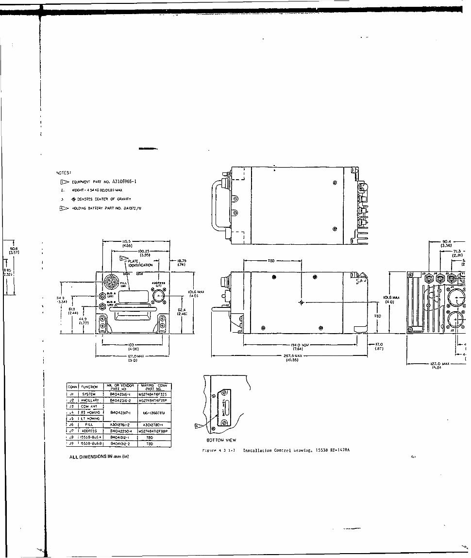
,-qOTES: ]COT> EQ . PART NO. A3105966-1 !.2
Z. WEHT- 4 54 KG (K0.OLS) MAX
.3 * DENOTES CENTER OF GRAVITY
3 HOLDING BATTERY PART NO. 8A1372/U
e
S115.5 - _90.4 -(45 (3.56)
90.6 71.3,(3.57) 00- . 71.3 -
(395) (2.8')BD
/ , ICATI 1 J.74)
2.32),1 n
549~~11. MAX~AiO.6
®I"@ @ <"us)- (40)
-l9 62.4(24)449 ~(2 TBD
(1,77)02
13- 194 0 NOW -17.0, ,?, .64( I.o,(406) (.67)__1 .- 4127.0 MAX 267.5 MAX - 41
(50) (10.55)127.0M
ICONNIUCTO T I O VENDOR MATING CONNFUNCTION__ -PART No PART NO.
it SYSTEM B4042316-1 mS27484T1&F32SJ2 IANCILLARY 840423:6-2 MS27484516F260
J3 COM ANT I
ATH 8 4042317-1 P, 36V5 T 84042s0, -
-J6 FILL _ AS012761-2 I A3012780-1 4
1J7 ADRO-ESS 1 8404225-1 luS274e4TI2198P
I a 535,8A I 84041312-, t8D BOTTOM VIEW
SJ t e jS e I 84041312-2 TSD
Figre 4 3 1-3 Installation Control1 braving, 1553B RT-1478A
ALL DIMENSIONS IN mm (in!

72 /U
90.0.479. (3. )
( (2.6 (740.2 -711
7 f .3 - T 3 9 )j 8 7 ' 25 TF A W R (74 90.6)
0 K
1 0) I0q.C7mu -(I67,
C62.4 (L.5 (2.77)02.4.
(27.0 1MAX-1 7. AX2~0
(10,12.0MA
127.0MA MAXIl 0
/AT 40 IWS27484TOV32S
I S27484T,61 26P
A30127e0-l
-S27-84T12F98P4190D BOTTOM VIEW199
S4 3 I- nstallation Control Drawing, 1553B RT-1478A
JC.,

NOTES>EOUPWNT PART No A3015968-1
VWE6HT-181KG(4 00 LB AX
'~DENOTES CENTER OF GRAVITY
.N FUCIO MATINGR CONN'1NARTCIO I NO PATN
iCONTROL 6 4042312-1 I MS3126 24-61S f .. '---" 2700(500)
TeD
4!0 - ;27 to 2 (-89 )I 881 ~(53651 )I 7
Mom 7290 74-p C7, (287)1.®
. 1 ( I ff / " 76 20 MAX
0 (I--14 0 - -30.0
(5)(1105 MA- 9' - PLATE., IDE TIFICATIONJ
(5.753 253.77)
(495)
ALL DIMENSIONS IN mm (in)
Figure 4 3 1-4 1l.,Itallatm Con'.Iol Drawing. Rad,, Set C-11466

P3015968-16) MAXr
IF GRAWhTYI
DRVNOR MATING CONN
42312 -I iS31261F21'S p 500)
T D
27 to 2 I (351)-73 0
I (2.87)
~-~ I76I 2~(.0)MA L(287 _ _ _ __ _ _
ED20EA D a i 464 I' I~ ~ ~ B-1 (m3 _ _
-46 05 MAX PLATE, IDENTIFICATIONf5 75) (3.77)
(495)
-DIMENSIONS IN mm (in)
(cr 4 3 1-4 1n.,tiAlaoIp Coflti Drering. Radl Set C-11466

_ _ S
4i-0 0
I-On
*/ ,
f t
o
q-74
62
I L,"--
-tiii"" 4 I F• S . ,
A 5 10
624

U ~ !I9O'8jo _
.1
I ' I, j I

I-I
~~ r i
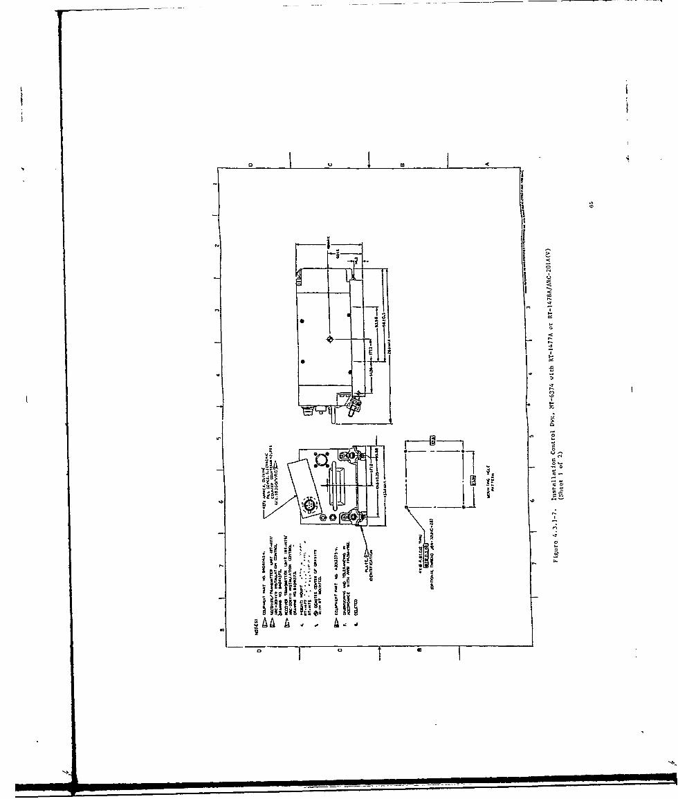
C U
JI
NN
0 I -
j I i IiI-
* I
' I N
.4t-

F-
0 U I
0I U
I --- I
w0 I
) I/ S.
'I I -~
& CU -4 oI -C.
'0 -1. '0
0 0
N~.
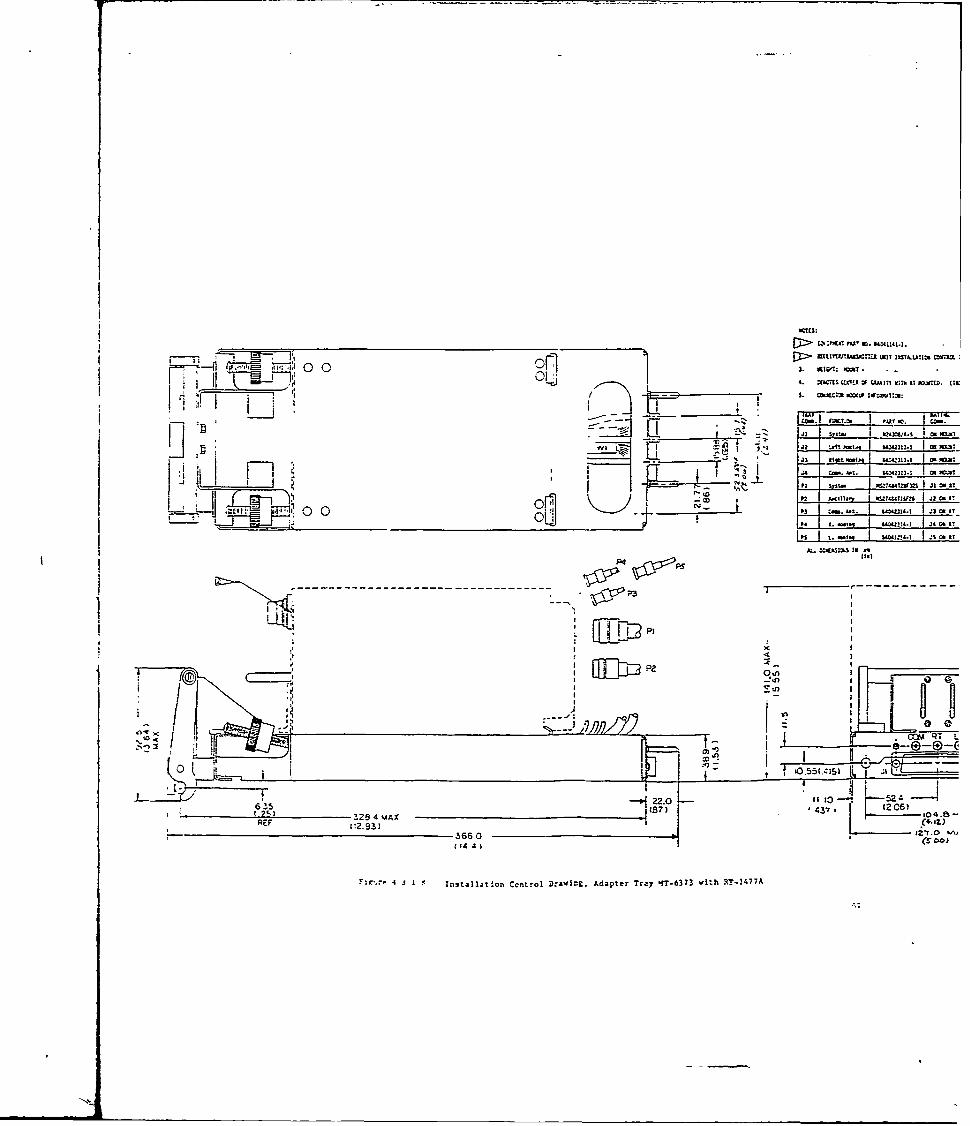
0 0 1EVI I _________________
JZ . C ________
.23zJ? LO k1-1. "W313-1 M -v.T
P1F~T -0T2 KltoILo 132 l4.I 0
Lj1Ijdi' 00 ___ r-m. 9W141j mI
A P4
P3 ---------
IPZ- qu6)
615 IB7) 43 25i 2) - 2 4 MAX '04.SREF 0.3 Cz
- 3660 I2zT.O 'A
(144) (.To
4 j 1- lnstall~tion Ccntrol Drawing. Adapter Tr&7 4T-6373 with RT!.47!A
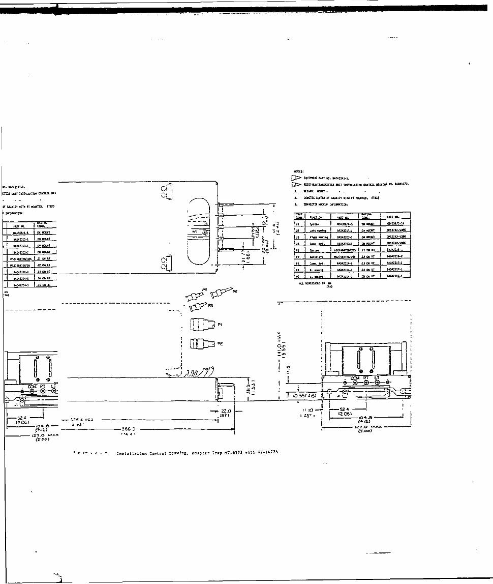
DI 2. IREC: PT I. sulll
4. Xbmst us I A:F l W .rIT. IT OA .Ic
IIy,- Un- -446
___ ___ __ __ __ tam* .3__ I . I___ ___ ___ ___ ni C.I IT__ PAJ .a
"1:!S-I is 0.IT AL
- I T~U - -2 - - -. - -* -~ -~~i- -i 3 aT 54
FET7-TTo Ia24L
lzt!4 VA 120 1 - .4.e
L ~~h- r ___________
0~JJ~@(4,1z .!66'i;.1'i-T.0
(Soo)LI_ _ 2 4 IItl ~nCn~lDz4=.AatrTa T67 !~
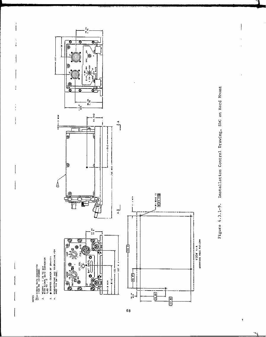
> 6
2z 7. 0
20 0X
684

AS
00
4-
69C

111 41'.. 111. I4 J
I.U I!
. i
r- 1
w
l l I r r
1A0
hI)11kb1 il
.. . .. . .. .b u l b +. -+ "
- ulket . bi"" t , ,
l i ., b (i i * • " I! . ! , w,.
1 -O., ,,h ji~ I4E ;+ ,
• II *I 2. I
IL _:__ ittti~ - tI * .
L*I
AS______
' *
1~i

0 ........... ..
.*K ,i I. Him I 1-a
i!L.s. Ii iI I a-
L .':;~~~ ...... =
1 1 it * litU 4* II " i,-"I .. ;I I I ;
__T i~llell
* "Us" I
... t I . f i
iit
mi .iL Il _ _!-
M ralll --
t j , .I.. .8 .. , ', i .
; ...-, l_ .... ... .,- ,d. t.,,.,..,,..... ..... , ii I 1
~ IIii~~L ~~ 1'i;1~9 ~ ~ di.' ~~;

I I......... IN .
P 0
I - - I N I i
I i
IM
ssIsi7 i O mi lljHN
----- ---- ---- ---- ----

r~l
M I!
c -- - - - -- - - - ------
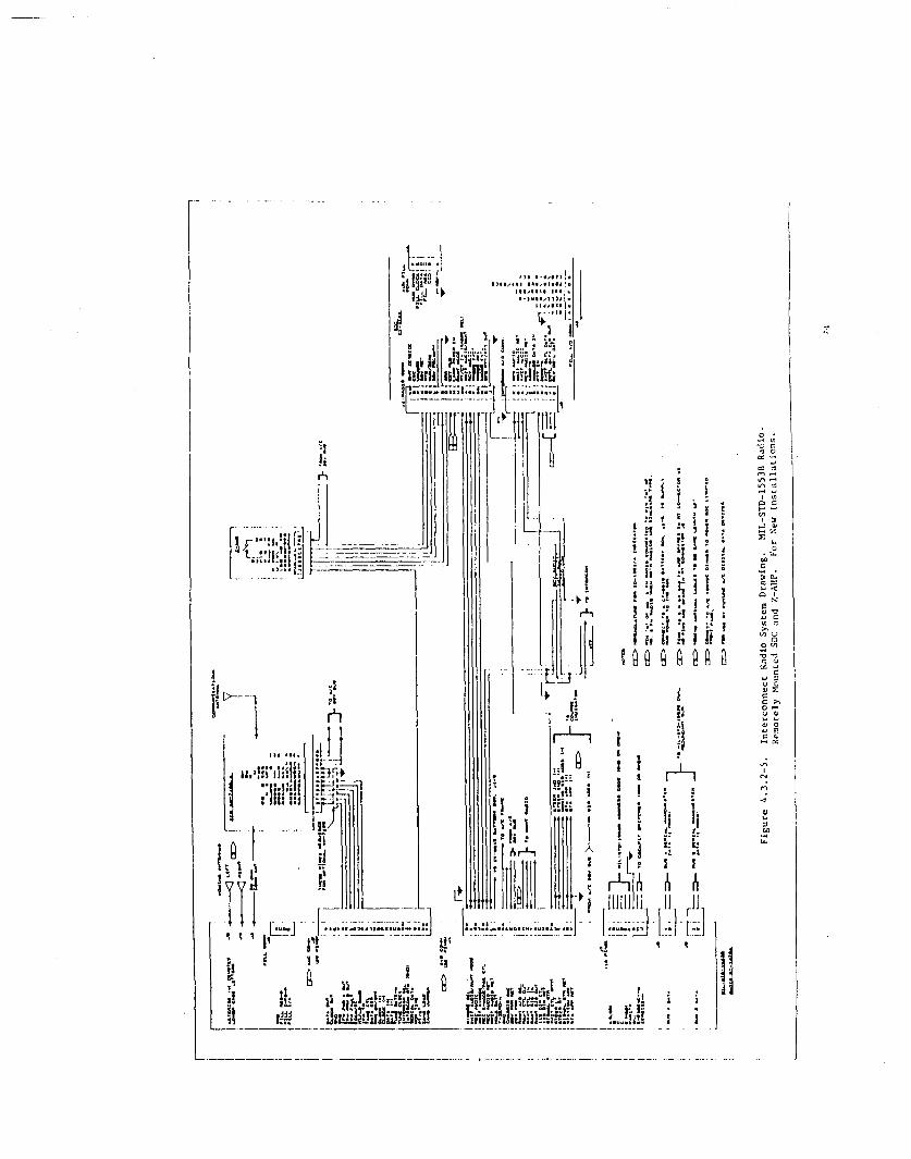
on OI* 0 .
L Ed
r-r-O
-h on N-
Im,~! I m! .~m11,A IM

r111
! ' 1-j ili
I--.-
*I 1 8-- fi - I I
:- ..... I , .
t AI i i Ii
• ~~~~~C r I "--- " ,' !
L t -:ij f ;+ ' 1"
0~~ c 0lt
-) 0
ia " ,! : s
I > I
!i + " " i
,, 0 n
__ _ _"f I -- -I I I
i! : ________-____________hilli?-liii !_ i i
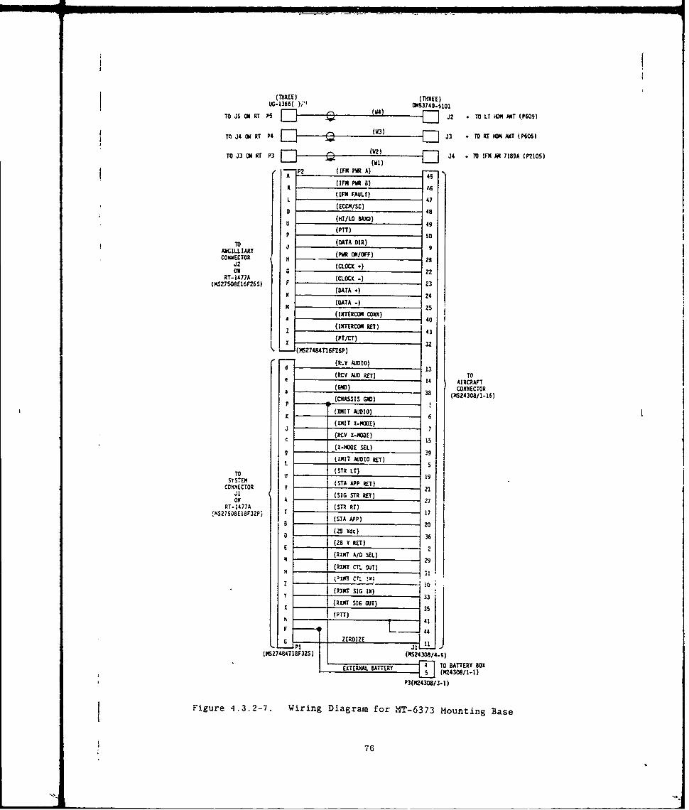
(THREE) (THREE)
UG-1366( );'I O1S3740-5101TO JS ON UT PS . W)L J2 ,, TO LT HM AR (.P6091
Mo J3 O,, T P3 A-- .Q TO! [--1 AN 719 (o,'2105)oWIz)
AP2 (IFM PWRA)7(1FN PR ) '6
L (IFM FAULV) 47
D (ECCM/sc) 48
I -- (HI/LO I SAO)
(PTT)TO ,(DATA DIR)
AJICILLIAPY (PRONOF 9CONNjECTOR H ( 01F)23
J2 ~ (CLOCK *)I
RT- 1477A .](CL.OCK -)1MS27508E16F26S) F (DT 23
K(DATA +) 24H (DATA) - 5
(INTERCOM CONN)Z, (INTERCOM REr)4
X €(Pr/CT) 32z
(MS27484TI6P2SP) 3
SAD13
(CY AUO RE) TOe 14 AIRCRAFT
(90o) CONNECTOR4 C A S S GD 38 (;24308 1-16)
K / (]DMT AUDO0)6
K 6JI (XMlr I-MoOE)7
( X-MOOE )15
9SYSTEM (STT) 39
L (XMIT AUIO RET)
TO U (STR LT) 1SYSTEM (STA AP P IT} It
CCNNECTOR v 21Ol (SIG STR RET)ON( A 27
RT-1477A (STR RT)27 8E81 3P) (STA APP) 17
B 2O
S(28 Vdc). (28 Y RET)
__ _ _ (RXMT AID SEL)
H _(RINT Cr OUT)
(:'XKT C,;
T PNTx SIG 1) 33
___ (PTT) 4
F ~ZERDIZE L 411P$27:4.T !8F32S1) (NS24308/4-5)
EXTERNAL "ERY TO BATTERY BOX
5(Y(24308/11)P3(S24308/3- 1 )
Figure 4.3.2-7. Wiring Diagram for MT-6373 Mounting Base
~76

I a:
000
ox 0 0 -i mo aa a, m _> 0. w U"0 J Z
0 Ij
1-4 1404 0
Cc x I j
14000
Iovc
of-"04- 77

provided with the various units of test equipment. The cabling between
units shall be in accordance with MIL-W-5088 and shall be so arranged that*the component parts are accessible. The power source shall be connected
into the test bench wiring and shall be protected by suitable fuses or
circuit breakers. Allow the required warm-up time for each piece of tes4
equipment. An alternate maintenance kit, the OA-9264A/ARC. may be used* with the procedures -nd diagrams described in TM-l1-5821-333-30.
4.4.1.1 Test Cable Diagrams. Those test cables which are considereda part of the Bench Test Setup are depicted in Figures 4.4.1.1-1 Lhrough4.4.1.1-6. The purpose and use of each cable is explained on theapplicable figure. Any equivalent cable or interconnect wiring may be usedespecially GFE cables and those cables which are part of the MK-994/AR testkit.
4.4.1.2 Standard Conditions. Standard conditions for theAN/ARC-20!A(V) shall be as follows:
a. Input voltage; 27.5 + 0.5, -0.0 Vdc.
NOTE: The voltage drop through the MK-994/AR is 0.5 Vd.. Thereforc.the voltage at the power source must be +28.0 + 0.5. -0.0 Vdc.
b. RF impedance: 50 ohms resistive.
c. Audio input signal (XMIT): 0 dBm into 150 ohms.
ungrounded. (387 mvrms)
d. Audio output signal (RECD): 50 mW into 150 ohim load(2.73 Vrms) (at 16 to 22 kHz p-p deviation).
e. Temperature: Room ambient (250 ± 50C).
f. Altitude: Normal ground.
g. Vibration: None.
h. Humidity: Room ambient
i. Standard analog voice test signal: A standard analogvoice test signal is defined as an RF signal that isfrequency modulated at 1000 Hz at ±6.5 kHz deviation from
a signal generator having an internal impedance of 50 ohmsresistive.
4.4.1.3 InntLPower. All power sources shall be in accordance with3.2.7.
4.4.2 Visual and Mechanical Inspection. All equipment shall beinspected for external damage. Remove all dust, dirt, foreign or packingmaterial. Check all external controls to see that they operate freely andproperly.
AIR/BO04-3 78
Nk

MS27484T 16F26p MS3126F24-6 iS
J DATA DIR. XPWR ON/OFFTO H COC P
RT-1477A" CLOCK (+) TANCILLARY CLOCK(-)CONNECTOR, F G
J2 N DATA (+. CC
- DATA (B) TO
C-11466AREMOTE
CONTROL UNIT
MS2748 4T18F32S CONNECTOR,
d RCY AUDIO CN ECO
RCV AUDIO RET B
L ____XMIT AUDIO RET KK
D +28 Ydc
E 28 Vdc RET bTO PTT PTTO
RT-1477A h C GrrSYSTEM CHASSIS d
CONNECTOR STEER LT d
STAAPP L
A SIG STR RET PTT IN
R NT
-XMIT AUDIO
(PIN K),D TAKE
CONTROL
115V, 400 Hzus PANEL ILLUM
=- 0- 115V RETURN0.0 -c
y T R A B U e h E L D K P d
MS3126E18-32PA
TO IK-994/AR CONNECTOR, J1 (RADIO SET NO. 1)
Figure 4.4.1.1-1. Test Cable No. 1 (RT-1477A Radio
to C-11466A Remote Control Unit
79

28V RET 28V DC
E RCV AUDIO K
TO 4-GROUND R STC
RT- 1476A pe2XMIT AUDIO SDCONNECTOR KX-MODE XMIT CONCO
* i X-MODE RCVb
hi SYSTEM PTT/PT. OUT xXSOD NT
MS27484T18F32S MS3126F16- JS
THIS CABLE IS USED TO CONNECT THE RT TO THE SDC.EQUIVALENT GFE CABLE MAY BE UTILIZED.
Figure 4.4.1.1-2. Test Cable Set No. 2 (RT-1476A to SDC)
80

L-
iL-J C-)
< Li
(SLjLJ Ci
I- >- LL-L.Oi
a. -j co VOLi -3
LL Cc
~ 4i
O.)~ LimC
I-J WL
0I L ! LL-U
LiQAc -j4A
_, Li CD LC5 U
L) ~ i 1..0 0 LiC'J P,4-40 D Icy_
CnC
o ~CD)I -a
a- CD m~
w- C.>i C.
fn C-181
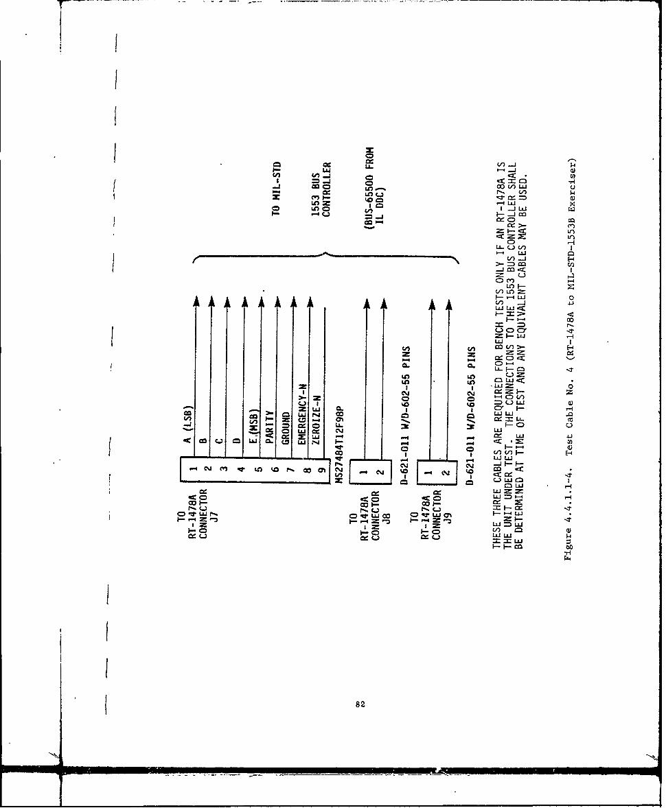
01 cc.. 0 s-0V)I
ko cc~ 1==QLc 1- ccLJ1-Ln 0 CA, I -jLL
cj = - -j m
-
L-. L
I-LLJ 0zV) -j
-j Jcc
C= mLO
VLOuj 0
00
-. %% ~ LL
-LL M C*
Ul)L LU
I I - W =
to =) LULLUJ
V Z IzI C, 00
CC. W-. Q- LULCLc U NM
LULUCV -j - I--
cm M t Ln W P-*CN-
CO ll 7082~

I
I MS312 E1..4-19S
K RCV AUDIO (.T TO OSCILLOSCOPEf TO A RINPUT
SDC L AUDIO RET
P PTT S1 switch is for the SDC
under test while S2 is forthe GS reference SDC.
SiL- OR
S21
Figure 4.4.1.1-5. Test Cable No. 5 Wiring Diagram fw0 MFSK Tests(Section 4.4.3.8.2) PIN K (EITHER CONN)
TO ' _ _"_ ._ _ _ _ _ _ TOMK-g94/AR .. _ _ _,,._ "_..,_ RTTEST SET
MS27473E18A-32PA 17 LEAOS* MS27484T18F-32S(OR EQUIV) (OR EQUIV)
THESE LEADS CONNECTTO JlSV, AC FOR PANELILLUMINATION (400 Hz,IF AVAILABLE)
FROM FROMPIN C PIN M
v WIRE FOLLOWING LEADS, PIN TO PIN:AB ,DE .J ,X.L.P ,TU ,V ,a.cd, ...h
NO CONNECTIONS REQUIRED TO FOLLOWING PINS:i F.G.H.R.,.W.X.Y.Z.S., .L
NOTE: INSERTS ARE SAME. ORIENTATION/KEYING T-l nTFF FrTFigure 4.4.1.1-6. Test Cable No. 6 (Jumper Cable for Connecting
MK994/AR System Cable, CS-10889/U, to RTSystem Connector Jl)
83
4.4.3 Test Procedures. (using the MK-994/AR)
NOTE: Input levels specified throughout the followingprocedures are based on the use of the MK-994/AR. Thesesignal levels include a tolerance for test equipmentvariations and the signal losses internal to the MK-994
(such as the 22 dB loss in received signal input and 0 3dB of RF loss in transmitter power between the radio andthe watt meter).F
4.4.3.1 Eguipment SetuP.
a. Connect the AN/ARC-201A(V) receiver-transmitter (eitherthe RT-1476A panel mount, the RT-1477A with C-11466Adedicated remote control unit or the RT-1478AMIL-STD-1553B bus control configuration) to the testequipment as shown in Figure 4.4.3.1-1. (For alternatepower meter connections refer to Figure 4.4.3.4.1-1: foralternate transmit audio input refer to Figure4.4.3.4.3-1.)
b. Place the following controls on the front panel of theMK-994/AR to the positions specified:
Conro Position
POWER DC Toggle switch ONRADIO ANTENNA FUNCTION selector switch XCVRRADIO TEST selector switch (S2) OFFCOMM CONT NO. 1 selector switch 1 (or any position
except ICS)COMM CONT 1 VOL control Set to a
comfortable levelCOMM CONT NO. 1 RECEIVER MONITOR switches (Switch positions
irrelevant)COMM CONT TEST SWITCH OFFADF TEST SWITCH OFFHEADSETS SWITCHES OFF
Place the RT controls as sDecified (front panel controls for the Panel
Mount RT or Remote Control Unit controls f3r the Dedicated Remote RT).(For an RT-1478A, all control functions are via the MIL-STD-1553B Data BusExerciser.)
lPosition
IFM RF PWR - OFF
PRESET MANMODE SCFUNCTION OFFVOLUME As requiredFREQUENCY See test reqm's
c. Perform the following bench tests (4.4.3.2 through4.4.3.9 in the sequence specified).
AIR/BO04-3 84

-4
Ca3
Ii - inCA cc uA
Ln CaLL
r-- C2~ . u -
5U q
C3: -W
C 0C 4!2
= %Cr, & .. 0U(A! , u JL:zP -b- w -RA mZr (A2 AJ C U -IU Mah. ?ZLAJ n LaiLa0C
= uj f -3 f J
4c0
(j~N U. 0 IIUJfCIO 41 U,
2 ___ ___U2_
(LA~ LJia
0 . 0 LA
0 0L
(4.*.
IP.-
ZLsJ W -
:0 co(
qp 1 2 U85

4.4.3.2 Power On. - self confidence tests
a. On the RT, set the Function switch to the TEST position.
b. Observe the Display on the RT front panel (or the RemoteControl front panel).
No keyboard entry is required. The display shall show 5
dashes for approximately one second.
No keyboard entry is required. The display indicates"E" and remains on for 3 seconds before progressing
to automatic test 9teps. This is to allow time for an
operator to move the switch to other positions if acomplete test sequence is not desired. After 3 seconds.the display automatically changes to:
This tests the operation of all segments of all digitsof the display. The display shall remain on for 3seconds and extinguish with the RT progressing to thenext automatic test step.
In the next auto test steps, the operation of the RT.the Data module, and the ECCM are verified in thisorder. All tests are under micro-processor control andrequire no additional operator action. Successfulcompletion of all tests shall be indicated by:
S0 0 1DI
"Good" shall remain on for 5 seconds and extinguish. TheRT shall then be left in the receive mode as inJicated bythe KEYBOARD, MODE or PRESET switches. Transmitterkeying is inhibited. Tests may be repeated by movingthe FUNCTION switch out of the TEST position and backagain.
AIR/BO04-3 86
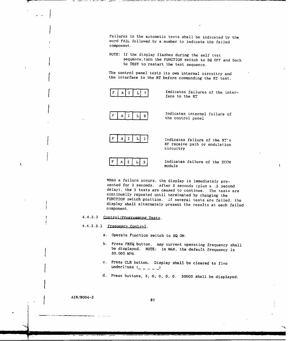
IFailures in the automatic tests shall be indicated by theword FAIL followed by a number to indicate the failedcomponent.
NOTE: If the display flashes during the self testsequenceturn the FUNCTION switch to SQ OFF and backto TEST to restart the test sequen3e.
The control panel tests its own internal circuitry andthe interface to the RT before commanding the RT test.
F I AI I Il Ll 7 1Indicates failures of the inter-face to the RT
I FIndicates internal failure ofiF A i J: 8the control panel
F A I II 11 Indicates failure of the RT'sHF receive path or modulationcircuitry
IF 1AII I Ll 3 Indicates failure of the ECCMmodule
When a failure occurs, the display is immediately pre-sented for 3 seconds. After 3 seconds (plus a .5 seconddelay), the 3 tests are caused to continue. The tests arecontinually repeated until terminated by changing theFUNCTION switch position. if several tests are failed, thedisplay shall alternately present the results at each failedcomponent.
4.4.3.3 Control/Programmina Tests.
4.4.3.3.1 Frequency Control.
a. Operate Function switch to SQ ON.
b. Press FREQ button. Any current operating frequency shallbe displayed. NOTE: In MAN, the default frequency is30.000 Mhz.
c. Press CLR button. Display shall be cleared to fiveunderlines (_ _)
d. Press buttons, 3, 0, 0, 0, 0. 30000 shall be displayed.
8J AIR/B004-3 87

e. Press ENT. The display shall blink indicating acceptance
of the frequency as valid and the radio shall tune to
30.000 MHz.
NOTE: The FUNCTION switch does not need to be in LD tochange frequencies when in MAN.
4.4.3.3.2 P.-eset Control.
a. Operate Function switch to LD.
b. Operate PRESET switch to 1. If any previous frequencyhas been preset, it will be displayed. If no previousfrequency has been preset, the display shall read FILLuntil a frequency is entered into the ?RESET tccording tothe following steps.
c. Press FREQ. The display shall show the displays previousoperating frequency.
d. Press CLR. The display shall be cleared to 5 underlines.
e. Press 3, 7, 8, 7, 5. 37875 shall be displayed. (Invalidentries will not be accepted or displayed.)
NOTE: if a mistake is made during frequency entry. pressingCLR will clear only the last digit entered to permitcorrection of an error. Once ENT is pressed, CLRshall clear entire display.
f. Press ENT. The display shall blink and the radio shalltune to 37.875 MHz.
g. Repeat steps b thru f for PRESET switch positions 2 thru6 where frequencies entered are 42.975, 45.375. 49.075.56.200, and 68.775 MHz respectively.
h. Repeat steps b thru f with PRESET switch set to CUEposition. Set in a frequency of 87.975 MHz.
4.4.3.3.3 Time Command Control.
a. Press TIME button. Display may read any number between 0and 99.
b. Press CLR. Display cleared to two underlines.
c. Press 0, 8 and ENT. The display shall blink and days 08shall be entered.
d. Press TIME button. Display will read some previous hoursand minutes separated by a space.
e. Press CLR. Display cleared to 4 underlines.
AIR/B004-3 88
... N

f. Press two digit buttons to represent hours in 24 hour
clock and two buttons to set in minutes, e.g.. 15 30represent 3:30 PM.
g. Press ENT. Display blinks and new time keeping starts at3:30 PM in example (seconds ire zeroed with the ENT).
h. Press TIME 3 times. Alternate fields of days,
hours/minutes and minutes/seconds will be displayed.
NOTE 1. The time keeping standard is the 3.2 MHz clock in
the synthesizer which has a long term accuracy of +5
ppm.
4.4.3.3 4 EM Control.
a. Set MODE to FH.
b. Set PRESET to any position.
c. Attach MX-18290/VRC FILL Device (PI) to FILL Connector onST. Turn power switch cn FILL Device to ON (refer to
appendix B for alternate device connections).
F d. Set Function Switch to LD and FILL Device variable selectswitch to 1 (or any position which has a desired HOPSETloaded).
e. Press LOAD switch once. (Successful transfer isindicated by a "beep" in headset and hopset numberindication on display. Unsuccessful transfer will resultin "bad" on display and continuous tone in headset.)
f. Press Sto and a preset channel number (e.g. !) whereHOPSET is to be stored.
g. Set Function Switch to SQ ON
NOTE: The test tape must be loaded into FILL Device prior touse. Procedures for loading the MX-18290/VRC from theKOI-18/TSEC and for loading the radio directly from theKOI-18 are contained in Appendix A.
4.4.3.3.5 Panel IIImination Control. The RT-1476A front panel andthe C-11466A remote control unit front panel (when used) utilize the A/C115V, 400 Hz ac bus supply for their electroluminescunt bick lighting.
The 115V AC is supplied to the RT-1476A panel through pins C and Ni ofsystem connector J1 and to the C-11466A panel through pins W and a ofconnector Jl. (Test cables No. 1 and No. e provide access to these pins.)
To verify dimming of the panel lighting, route the llSV, 400 Hz AC viaa variac to permit operator control of the AC input. Decrease the inputvoltage to dim the panel illumination and increase the input voltage tobrighten the panel illumination. (Do not exceed the 135V maximum.)
AIR/B004-3 89
N89

4.4.3.4 Transmitter Tests.
4.4.3.4.1 Power Outout and Sidetone Tests. (Use test setup shown in
Figure 4.4.3.4.1-1)
a. Set the RT PRESET switch to MAN and MODE switch to SC
(either from front panel or from remote control unit as
applicable).
b. Set in a frequency of 30.000 MHz via the frequency select
push buttons in accordance with 4.4.3.3.1. The display
shall read 30000.
c. Set the RT IFM RF PWR switch to OFF and Function switch
to SQ ON.
d. Place and hold MK-994/AR HEADSETS INTERCOM/TRANSMITtoggle switch 1 in the transmit position.
e Speak intb the headset microphone and listen for audible
sidetone in the headset. Adjust the volume control onthe RT-1476A or the C-11466A Audio control (Ps
applicable) for a comfortable listening level.
f. Observe an RF power indication of 10 watts. +5.8. -3.7
watts (+40 dBM ±2 dB) RECORD. (Take into account any RF
attenuators and the MK-994 loss.)*
g. Release transmit switch on WK-994A.
h. Repeat steps (b) thru (g) for each of the 6 presets and
the CUE position of the RT PRESET switch (frequencies of
37.875, 42.975. 45.375, 49.075, 56.200, 68.750. and
87.975 MHz).
For alternate test setup shown in Figure 4.4.3.4.1-1. a
typical loss is 30.0 dB for the attenuator plus 0.3 dB
for MK-994 or a total of 30.3 dB. The meter readings or
acceptable power would then be 5.9 mw to 14.8 mw.
4.4.3.4.2 Freaiency Check.
NOTE: (1) if RT has been on for at least I minute, continue
with test. If not, wait 1 minute before continuing.
(2) Unkey transmitter when changing frequencies.
a. Connect tne AN/ARC-20!A(V) RT (either configuration) to
the test equipment as shown in Figure 4.4.3.4.2-1.
b. Set the RT PRESET switch to MAN and verify a frequency of
30.000 MHz on d1splay. (If frequency is not 30.000. setit using the push buttons). This is fo (centerfrequency).
AIR/BO04-3 90

+28 VdcTEST CABLE C-O8/R
J28 J2TEST jqICG3477IU*
J11 FACILITIES .46U
RECEIVER J3 KITWATERTRANMITERr M-994/AR j1o
RT-1476A X18/*
TEST CEST
TESTT CABL P
J11 FAILTIST9
EXERCISE
Figure~~~~~TS 4.C..-. eoeAndBwEr Oupu1T
RADIO TO W94AJ
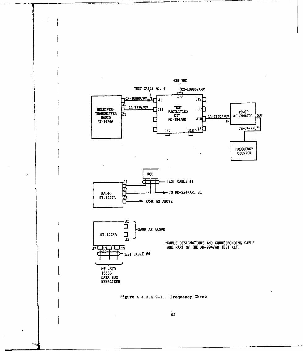
+28 VoC
fTEST CABLE NO. 6 JCX-lO86/Ajt*
J28
TRNMTE 3KIT 40 ~ ATTENUATOR OUT
RADIO ~ ~ ~ T r K-994/AR, J1 dl 24O/
RT-147A I
-CUTEST CABLE #1
DT1A 3SAME CISERV
SiguE AS.421 FrOEqecCek
RT-1478
NJ3
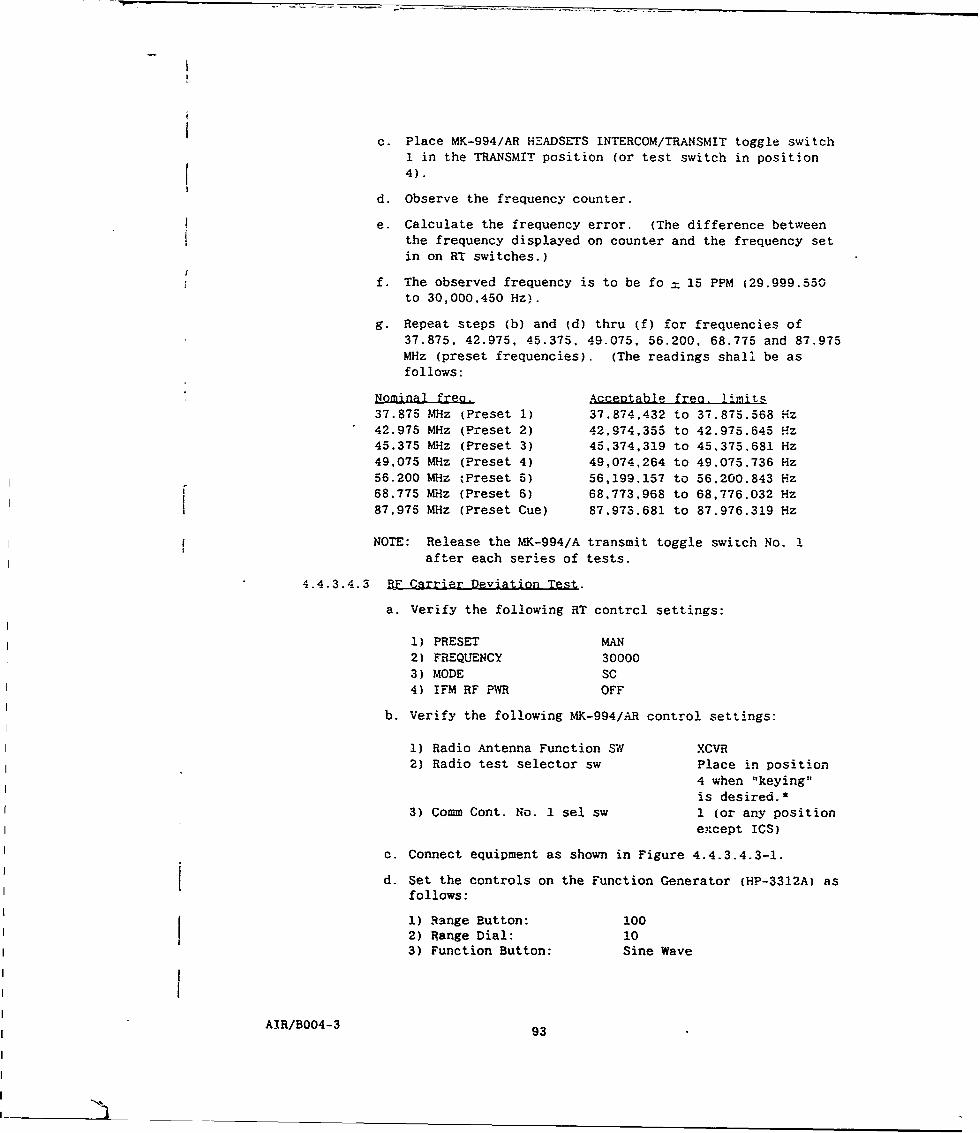
c. Place MK-994/AR HEADSETS INTERCOM/TRANSMIT toggle switch
1 in the TRANSMIT position (or test switch in position4).
d. Observe the frequency counter.
e. Calculate the frequency error. (The difference betweenthe frequency displayed on counter and the frequency set
in on RT switches.)
f. The observed frequency is to be fo = 15 PPM (29.999.550to 30,000,450 Hz).
g. Repeat steps (b) and (d) thru (f) for frequencies of37.875, 42.975, 45.375, 49.075, 56.200, 68.775 and 87.975MHz (preset frequencies). (The readings shall be asfollows:
Nominal freo. Acceptable free. limits37.875 MHz (Preset 1) 37.874,432 to 37.875.568 Hz42.975 MHz (Preset 2) 42,974,355 to 42.975.645 Hz45.375 MHz (Preset 3) 45,374,319 to 45,375.681 Hz49,075 MHz (Preset 4) 49,074,264 to 49.075.736 Hz56.200 MHz tPreset 5) 56,199.157 to 56,200,843 Hz68,775 MHz (Preset 6) 68.773,968 to 68,776.032 Hz
87,975 MHz (Preset Cue) 87,973.681 to 87.976.319 Hz
NOTE: Release the MK-994/A transmit toggle switch No. 1after each series of tests.
4.4.3.4.3 BE Csrrier Deviation Test.
a. Verify the following RT contrcl settings:
1) PRESET MAN2) FREQUENCY 300003) MODE SC4) IFM RF PWR OFF
b. Verify the following MK-994/AR control settings:
1) Radio Antenna Function SN XCVR2) Radio test selector sw Place in position
4 when "keying"
is desired.*3) Comm Cont. No. I sel sw 1 (or any position
except ICS)
c. Connect equipment as shown in Figure 4.4.3.4.3-1.
d. Set the controls on the Function Generator (HP-3312A) asfollows:
1) Range Button: 1002) Range Dial: 103) Function Button: Sine Wave
AIR/B004-3 93

TEST CABLEST
TO 553 ~AU. DSIGATO+SAN COES ODL AT N
AN ATERATE ONNCTIN FO THS LANALYTOZEROFTH
MK9/TEST ST
ECIgu r4.4.3.4.3- 1 FACarrTIEr Deiato Tes
TRANSITTERJI K4
RAI KwA l

Adjust the generator's amplitude vernier for a nominal 387mVrms indication on the voltmeter (Fluke 8050A). Make thisadjustment with the RT in transmit mode or "keyed". If thealternate test set-up on Figure 4.4.3.4.3-1 is used, thenominal generator output is 530 mVrms and the adjustment isvery critical. (The connection to pin K is therefore thepreferred choice.)
* Place switch in position 3 and "key" with HEADSETSINTERCOM/TRANSMIT toggle switch 1 (see section 4.4.3.4.1d)if alternate test connections shown in Figure 4.4.3.4.3-1are utilized.
e. Set the controls on the Modulation Analyze' (HP-8901B)as follows:
1) HP Filter: 50 Hz2) LP Filter: 15 kHz3) Depress the automatic operation key.
f. Depress the peak (+) key on the modulation analyzer andthe FM measurement button.
g. Key the transmitter and observe and record (on the test
data sheet) the modulation deviation displayed on themodulation analyzer. Depress the peak (-) key and recordthe deviation. Add the peak (+) and peak (-) deviations.The required pp deviation is 16 to 22 kHz p-p (includessquelch tone).
h. Unkey the transmitter (test switch to any position except
4 or 8). Alternate: Release HEADSET transmit switch 1.
i. Set the RT preset Switch to Preset 1 (37.875 M~iz), keythe transmitter and record the indicated deviation as in
step g above. Unkey the transmitter.
j. Repeat step i for the remaining preset frequencies of
42.975, 45.375, 49.075, 56.200, 68.775, and 87.975 MHz.
4.4.3.5 Receiver Tests.
4.4.3.5.1 Analow Sensitivity.
a. Verify control settings for RT as follows:IFM RF PWR OFFPRESET MANFUNCTION SQ OFFMODE SCFREQ DISPLAY 30000
AIR/B004-3 95

b. Verify the control set,.ings for MK994/AR as follows:Radio ant. function XCVRRadio test 6
Comm Cont. No. I sel. sw 1 any position exceptICS1
Headsets/Intercom switches OFFComm Cont. No. 1 toggle switches OFFComm Cont. Test sw OFFADF switches OFF
c. Connect the equipment ;. shi-n in Figure 4.4.3.5.1-1.
d. On the 8903A audio anzlyzer, set the source frequency toI kHz.
e. Adjust the FM signal generatol to 30.000 MHz: FM externalmodulation (AC); deviation ±6.5 kHz by adjusting the8903A audio amplitude as required; output level ofapproximately -77 dBm. NOTE: The 8903A audio amplitudecan be stepped up or down with the arrow buttons afterthe AMPTD button is depressed. The size of the steps isadjusted with the AMPTD INCR button and the keyboardnumbers.
f. Disable 8903A HP filters, activate 30K LPF.
g. Using the RT or RCU volume control, adjust the audiooutput level (volume) of the RT for I Vrms nominal.Press a and SINAD buttons on the 8903A.
h. Adjust signal generator output level until a 10 ± .5 dBSINAD is obtained. (The level shall be ,-105 dBm at theradio input). ( -83 dBm at the signal generator output)
i. Repeat steps d thru h (as applicable) for RT PRESETS 1thru 6 plus CUE. The frequencies will be 37.875, 42.975.45.375, 49.075, 56.200, 68.775 and 87.975 MHz.
4.4.3.5.2 SQuelch and Volume Control Tests.
a. Connect equipment as shown in Figure 4.4.3.5.2-1 (see
Figure 4.4.3.5.2-2 for audio combiner network details).
b. Set PRESET to MAN (30 MHz) and Function to SQ ON.
c. Set the signal generator to 30.000 MHz, modulation at FM.EXT (AC).
d. With function generator #1 off, set function generator #2for 1 kHz and adjust its output level to obtain 6.5 kHzdeviation on the signal generator (with the signalgenerator output connected to 8901 mod meter set todisplay for FM deviation).
AIR/B004-3 96
9.

1SAME AS
'RT-1478A
BELOW
TES ELECTRICALESJ8 COUOAE
MIL-STD15538DATA BUS +8VCF O
EXERCISER TEST CABLE SIGNA IN
THE . 6UI OUTPUT)Ut ATRAO
ARESITE PAll C THEIK4A EST KIT
RTSEE6 KlI TR 4.4.3.4. -1M JU WORTTLERTATPOWER MET R INNCTO
Figure ~ ~ ~ J1 4..351.i Reeve esi1iy et
ME UDI OUPUTAT9ES
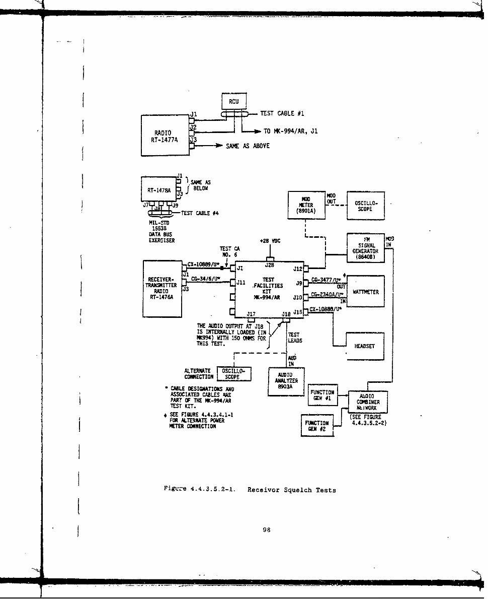
-CU TST CABLE #1
-RADIO -TO MK-994/AR, J1RT-14774 AEA BV
1. S M SAE AS
RT-1478A 3 J BELOW MOD mooJ7Q J9' mOCLO~TEST OCILLO-NILT~~T CABLE #4T, (SCOPEMIL-SrTO
1553BDATA BUS -_ mooEXERMTSER +28 VOc
TEST CA |I .. r. o h_ N-- I I -,XAOB
S.* I-.3 J28 J12
RECEIVER- CG-3416/U' TEST 9 CG3477.ITTERFACILITIES OU
RADIO J3 KITRT-1476A W-M9/AR I1NI" ,, "ICX-1O888/tP
J 1 7 3 1 8 J 5
THE AUDIO OUTPUT AT J18IS INTERNALLY LOADED (INI TESTNK994) WITH 150 OHMS FOR" LEADTHIS TEST. - i " )- H S]ET
I IAUIN
ALTERNATE OSCILLo- iCONNECTION I SCPE L J AUDIO,------- , ( ANALYZER -- ' -
SCABLE DESIGNATIONS ANO FUNCTIONASSOCIATED CABLES ARE GN# UIPART OF THE MK-994/AR CMIETEST KIT. L I
* SEE FIGURE 4.4.3.4.1-1 (SEE FIGUREFOR ALTERNATE POWER IFUNCTION 443522METER CONNECTION G .#2
Figuze 4.4.3.5.2-1. Receivor Squelch Tests
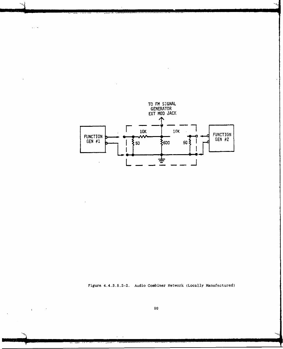
TO FM SIGNALGENERATOR
EXT MOD JACK
FUNTIO 10 VWFUJNCTIO N
GE 150 600 GEN #2
1E r
Figure 4.4.3.5.2-2. Audio Combiner Network (Locally Manufactured)
99

e. With function generator #2 off, set function generator #1for 150 ±3 Hz and adjust its level to obtain 3 kHzdeviation on the signal generator. (See step d.) (NOTE:The 150 Hz must be held w-thin its stated tolerance.)
f. Turn both function generators on for a combined 150 Hzand 1 kHz modulation of the signal generators (with thecombined displayed deviation between 8 and 9.5 kHz).
( g. Set the signal generator output level to -103 dBm andconnect to J12 on the MK 994/AR.
h. With test switch on the MK 994/AR in position 6. measurethe audio level out of the RT at J18 of the MK-994/ARtest set with the audio analyzer. In lieu of using theaudio analyzer, the audio can be viewed on anoscilloscope as shown in Figure 4.4.3.5.2-1.
i. Increase the. signal generator level slowly until thesquelch breaks. The audio output level is to be greaterthan .5 volts. Record.
j. Decrease the signal generator level until the squelchreturns. The audio output level is to be less than 0.5volts. Record.
k. The radio shall break squelch at -1i15 dBm.
1. Set PRESET to 5 (56.2 MHz).
m. Repeat Steps c thru k (as applicable) for a frequency of56.200 MHz.
n. Increase signal generator level to -22 dBm.
o. Vary the audio control on the RT (or remote control unit)
over its control range. The audio output level shall
vary over a 35 to 40 dB range with minimum at ccw end and
maximum at cw end of control rotation (nominal RT outputis +17 dBm (50 mW). (Range is approximately 2.5 gW to
50 mW.) [It may be desirable to measure the audio levelwith a Fluke 8050 (or equivalent) set on the 20V range.]
4.4.3.6 Homing Tests.
a. Connect the equipment as shown in Figure 4.4.3.6-1. (RFpath losses in the MK-994/AR are compensated for with theRF signal generator output level settings listed.)
b. On the MK-994/AR, set the radio test switch to position 8and radio antenna function switch to HOMING BALANCE.
c. On the RT, set the mode switch to HOM.
AIR/B004-3 100
ww

'JJJ
- o
+-JLU tO cm
a1 11m CD,-a-ItJ 4 -
La !Q -9.'/) ccim"i4A4
494
LL 9 __ __ __ __ _
CLCV)
0 101

d. Set the signal generator (connected to J12 of theMK-994/AR) to Preset No. 3 (45.375 MHz) at a -84 dBmoutput level (-112 dBm at homing antennas). Signal
generator can be either modulated or unmodulated forthese tests.
e. Increase the signal generator level until the signal
strength flags on the tK-994/AR homing meter flip to allsolid color. This should occur between -85 and -65 dBm(-113 and -93 dBm at RT).
f. Increase the signal generator signal level to -2 dBm (-30dBm at RT). The station approach indicator on the homingmeter should be positioned at the bottom of its range(goes from top to bottom as the RT's signal is increasedfrom approximately -80 to -2 dBm). (Appproximately -108to -30 dBm at the RT.)
g. Set the ANTENNA FUNCTION switch on the MK-994/AR to theHOMING RIGHT position (signal from signal generator to
J12 is 3 dB greater than signal to J13).
h. The steering indicator pointer shall point to the extremeright position on the MK-994/AR homing meter.
i. Set the ANTENNA FUNCTION switch on the MK-994/AR to theHOMING LEFT position.
j. The steering indicator shall point to the extreme leftposition.
4.4.3.7 Verification of IFM AM-7189A Amnlifier Control Signals.
a. Use test set-up for transmitter power output and sidetone
tests (Figure 4.4.3.4.1-1).
b. Connect a resistive network as shown to the designatedpins at the RT Ancillary connector (J2).
47K
47KR
D l ( )47KDk +5 Vdc
u I ( 47K
3 47K
0, (D (D 0, ( are voltmeter test points.
SAIR/BOO4-3 102

c. On the RT. set MODE to SC. FUNCTION to SQ OFF. PRESET toMAN 30.000 MHz), IFM RF PWR to OFF.
d. On che MK-994/AR, set RADIO ANT FUNCTION to XCVR, TEST to
1, COMM CONT No. 1 selector to 1, COMM CONT No. 1
RECLIVER MONITOR switched to OFF, COMM CONT test switch,ADF test 8 switch, and HEADSET switches to OFF.
e. Key the transmitter by placing the MX-994/AR HEADSETSINTERCOM/TRANSMIT toggle switch 1 to transmit position.
f. Speak into the headset microphone and verify the presence
of a sidetone signal (adjust volume control for sidetonelevel). Release "key" switch.
g. Set IFM RF PVVR switch to LO; then to NORM; then to HI(unkey before changing settings). In each position."key" the transmitter.
h. Note the absence of sidetcne for each of the switch
settings of step g.
i. Set IFM RF P". switch to OFF and "key" the transmitter.
j. Monitor each of the test points (TPs) of step (b) with avoltmeter. The voltage readings shall be +5 volts fortest points Q. ®, and ® and OV for TPs and
k. Unkey the transmitter and monitor each of the five testpoints. The voltage readings shall be +5 volts for TPs
, , /N , and ® and OV for TP
1. Set the iFM RF VWR switch to LO and monitor the 5 test
points. The voltage readings shall be +5 volts for TPsS and and V for TPs and
m. Set the IFM RF PWR switch to HI and monitor the 5 TPs.
The voltage readings shall be +5 volts for TPs- and®and 0 volts for TPs and
TsQ, v )n. Set the IFM RF PWR switch to NORM and monitor the 5 TPs.
The voltages shall be +5 volts for TPs and-@and 0V for TPs Q and Q
o. Set the MODE switch to FH and monitor the 5 TPs. Thereadings shall be +5 volts for TPs @ and @ and OV forTPs , , and®.
p. Set the MODE switch to SC and set in a frequency of62.000 MHz with frequency buttons (refer to section4.4.3.3.1 for entering a new frequency in MAN position).Monitor the 5 TPs. The voltages shall be +5 volts at TPs
®'0 ,,, . and @ and OV at TP
q. Reset frequency to 30.000 MHz.
AIR/BO04-3103
iN

4.4.3.8 Sinz -anel SysteM Tests. For these tests, a second RT(GFE) and two each Signal Data Converters (SDC) will be required. Inaddition, two handsets (H-250/U) or two intercoms (C-6533) equipped withheadsets (H-157/AIC or H-lO1/AIC) are required.
4.4.3.8.1 Piain Text Voice.
a) Connect the equipment as shown in Figure 4.4.3.8.1-1.
b) On each RT, set the following switches:1) PRESET MAN2) FRf.Q 30.000 MHz (no offset)3) MODE SC4) FUNCTION SQ ON5) IFM RF PWR OFF
c) On each SDC, fill the variable locations as described inAppendix A, and set the following switches.1) MODE PT2) VAR 13) DATA RATE TF4) "*" OFF
d) If intercoms are used, set all toggle switches to OFF andset rotary switch to position 5.
ei With one operator at RT #1 (UUT) Headset/Handset and asecond operator at RT #2, proceed as follows:
1) Opr. #1 to operate PTT on handset and speak intomicrophone #1.
2) Opr. #2 should hear the voice signal of Opr. #1 in the#2 headset.
3) Repeat for Opr. #2 transmitting to Gpr. gI.
4.4.3.8.2 Cipher Text Mode.
a) On each SDC, set MODE to the RM7/CT position.
b) Repeat (e) of 4.4.3.8.1 above to verify CT voice
communication.
4.4.3.8.3 Frequency Shift (FSK).
a) Connect the equipment as shown in Figure 4.4.3.8.2-1.
b) On each RT, set the following switches:1) PRESET MAN2) FREQ 30.000 MHz (no offset)3) MODE I
4) FUNCTION SQ ON5) IFM RF PWR OFF
AIR/BO04-3 104

IL
LLI-
-CC im cJ t
LLI-L M)I
no 4J
ZCJ iii
r:i.-,O
LO C.D
L&J LLJ 4 !~-
CAD-l M 41
~~I-o i-4n-
W (J V) ui0w C W) 5...&5 C
0w 1
-44
Ln 4h
-4 C14
........
4.,
I-I
105

.LJ-0
LLULL1- -LO
C,, 4
v-
CM-
En 0
c-4
0 106
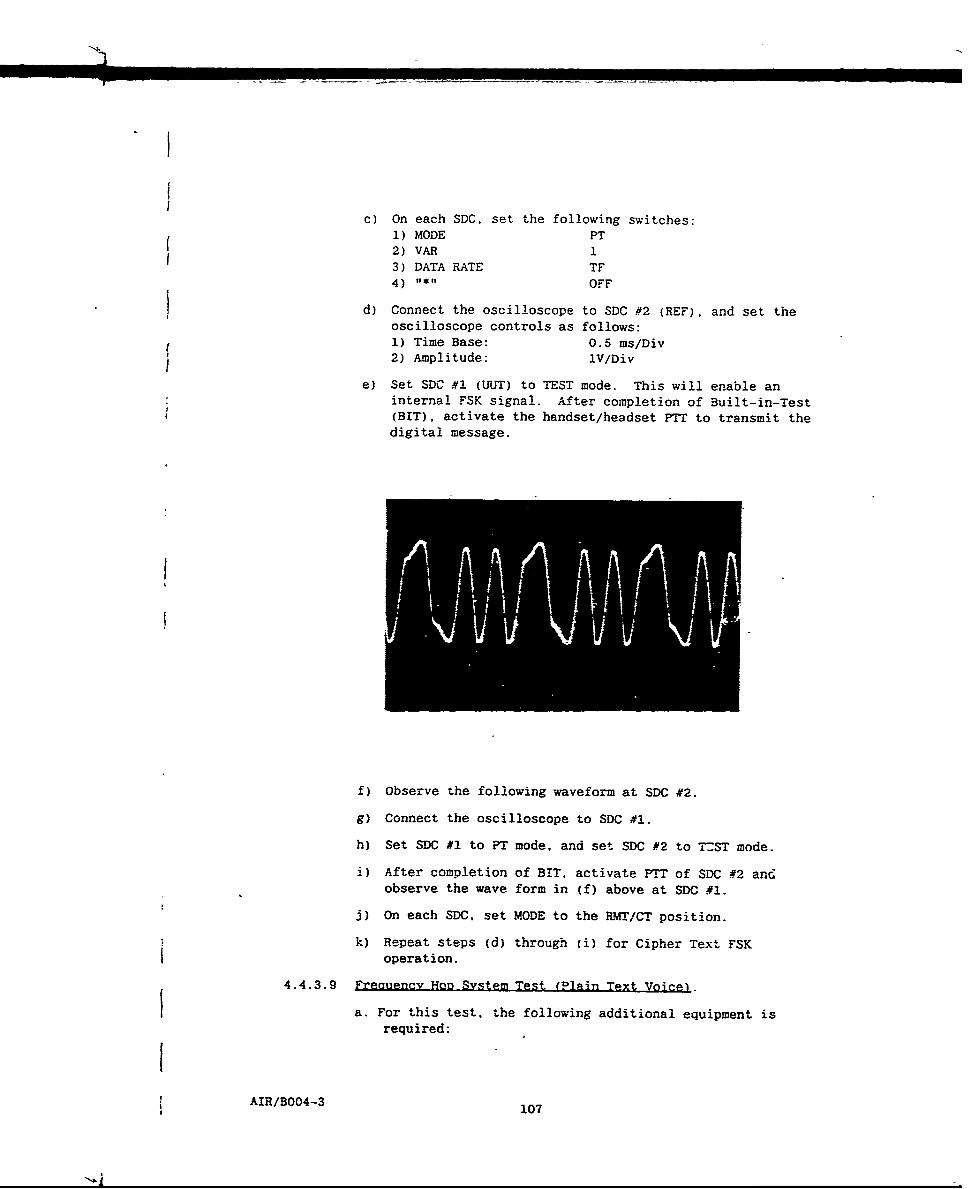
c) On each SDC, set the following switches:1) MODE PT2) VAR 1
3) DATA RATE TF4) 0 OFF
d) Connect the oscilloscope to SDC #2 (REF), and set theoscilloscope controls as follows:
1) Time Base: 0.5 ms/Div2) Amplitude: iV/Div
e) Set SDC #1 (UUT) to TEST mode. This will enable aninternal FSK signal. After completion of Built-in-Test(BIT), activate the handset/headset PTT to transmit thedigital message.
f) Observe the foilowing waveform at SDC #2.
g) Connect the oscilloscope to SDC #1.
h) Set SDC #1 to PT mode, and set SDC #2 to T-ST mode.
i) After completion of BIT, activate PTT of SDC #2 andobserve the wave form in (f) above at SDC #1.
j) On each SDC. set MODE to the RMT/CT position.
k) Repeat steps (d) through (i) for Cipher Text FSKoperation.
4.4.3.9 Freauency Hon System Test (Plain Text Voice).
a. For this test, the following additional equipment isrequired:
AIR/B004-3 107
10
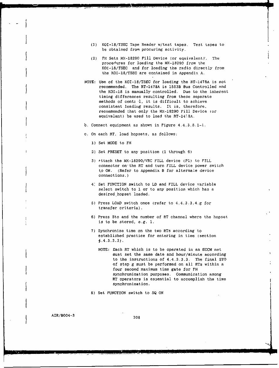
(1) KOI-18/TSEC Tape Reader w/test tapes. Test tapes tobe obtained from procuring activity.
(2) FH Sets MX-18290 Fill Device (or equivalent)'. Theprocedures for loading the MX-18290 from theKOI-18/TSEC and for loading the radio directly fromthe KOI-18/TSEC are contained in Appendix A.
NOTE: Use of the KOI-18/TSEC for loading the RT-1478A is notrecommended. The RT-1478A is 1553B Bus Controlled andthe KOI-18 is manually controlled. Due to the inherenttiming differences resulting from these separatemethods of conti i, it is difficult to achieveconsistent loading results. It is, therefore,recommended that only the MX-18290 Fill Device (orequivalent) be used to load the RT-14'8A.
b. Connect equipment as shown in Figure 4.4.3.8.1-1.
c. On each RT, load hopsets, as follows:
1) Set MODE to FH
2) Set PRESET to any position (1 through 6)
3) Attach the MX-18290/VRC FILL device (PI) to FILLconnector on'the RT and turn FILL device power switchto ON. (Refer to Appendix B for alternate deviceconnections.)
4" Set FUNCTION switch to LD and FILL device variableselect switch to 1 or to any position which has adesired hopset loaded.
5) Press LOAD switch once (refer to 4.4.3.3.4.g fortransfer criteria).
6) Press Sto and the number of RT channel where the hopsetis to be stored, e.g. 1.
7) Synchronize time on the two RTs according toestablished practice for entering in time (section
1.4.3.3.3).
NOTE: Each RT which is to be operated in an ECCM netmust set the same date and hour/minute according
to the instructions of 4.4.3.3.3. The final STOof step g must be performed on all RTs within afour second maximum time gate for FHsynchronization purposes. Communication amongRT operators is essential to accomplish the timesynchronization.
8) Set FUNCTION switch to SQ ON
AIR/BO04-3 108
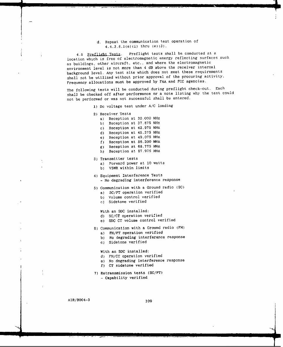
d. Repeat the communication test operation of
4.4.3.8.1(e)(1) thru (e)(3).
4.5 Preflight Tests. Preflight tests shall be conducted at a
location which is free of electromagnetic energy reflecting surfaces such
as buildings, other aircraft, etc., and where the electromagnetic
environment level is not more than 4 dB above the receiver internal
background level. Any test site which does not meet these requirements
shall not be utilized without prior approval of the procuring activity.
Frequency allocations must be approved by FAA and FCC agencies.
The following tests will be conducted during preflight check-out. Each
shall be checked off after performance or a note listing why the test could
not be performed or was not successful shall be entered.
1) Dc voltage test under A/C loading
2) Receiver Testsa) Reception at 30.000 MHz
b) Reception at 37.875 MHz
c) Reception at 42.975 MHz
d) Reception at 45.375 MHz
e) Reception at 49.075 MHzf) Reception at 56.200 MHz
g) Reception at 68.775 MHz
h) Reception at 87.975 MHz
3) Transmitter testsa) Forward power at 10 wattsb) VSWR within limits
4) Equipment Interference Tests- No degrading interference response
5) Communication with a Ground radio (SC)
a) SC/PT operation verifiedb) Volume control verified
c) Sidetone verified
With an SDC installed:
d) SC/CT operation verified
e) SDC CT volume control verified
6) Communication with a Ground radio (FH)
a) FH/PT operation verifiedb) No degrading interference response
c) Sidetone verified
With an SDC installed:
d) FH/CT operation verified
e) No degrading interference response
f) CT sidetone verified
7) Retransmission tests (SC/PT)- Capability verified
AIR/BO04-3 109
N_ _

Nf
4.5.1 Electrical Power Source. With all electrical equipment which
is connected to the same bus as the AN/ARC-201A(V) turned ON and operatingin the normal manner (if an SDC is installed i- should be operating in PTmode), place the AN/ARC-201A(V) in the transmit mo-de of operation. Underthis condition, measure the DC input voltage level at pin D of connectorJl. The voltage shall be between +24 and +29 Vdc.
4.5.2 Test Eauioment Resuired. A compatible SINCGARS type Ground orAircraft radio is required as a ground reference system for the preflightcommunication test of the AN/ARC-201A(V). If the system under test isconfigured with an SDC, the reference Ground SINCGARS equipment must be ofthe ICOM type (RT-1523/VRC) or be equipped with a KY-57 (or compatibleCOMSEC device), and the Aircraft SINCGARS equipment must be equipped withan SDC or KY-58. An RF thru-line wattmeter is also required. If anon-SINCGARS radio is used, a deterioration of communication quality mayoccur due to a difference in FM deviation utilized in the two radios.
4.5.3 Receiver Tests.
a. Set the RT-1476A front panel controls. RT-1477A/Cl1I466A.remote unit panel controls, or RT-1478A data bus controlsto accomplish the following:
IFM RF PWR OFFPRESET MANFREQ 30.000 MHzFUNCTION SQ ONMODE SCVOL As required
b. If an SDC is installed, set the front and rear switchesto the following:
MODE PT
VAR IRATE TF"1*1 OFF
c. Connect the equipment for the RT (and optional SDC) undertest as shown in Figure 4.5.3-1.
d. For the ground station, select a 30.000 MHz frequency andkey the transmitter. Operate at the lowest RF outputpower available. Speak into the microphone.
e. Verify the receiver under test by monitoring thereception in the headset.,
f. Repeat steps c and d at PRESET frequencies of 37.875.
42.975, 45.375, 49.075, 56.200, 68.775 MHz and at CUEfrequency of 87.975 MHz.
NOTE: It is assumed that the six presets and the CUE
frequency have been previously set in both RT'saccording to the instructions of section 4.4.3.3.2.
AIR/B004-3 110
J - p
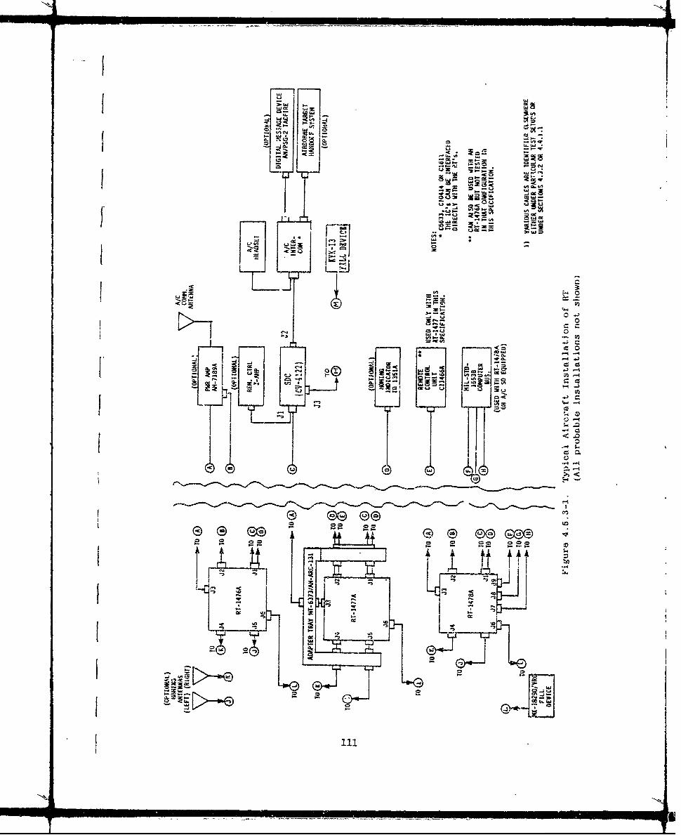
~w ,.j
-~ 0 -0
0.20
_4 0-C6
cc U,ci* C en
J , w c
=~~- 2 t=' ntn0
0- 4j
oii-.
*. U
*e Gee -
cc0 .. 4
I.~L woe -
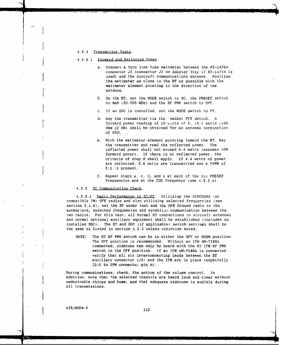
4.5.4 Transmitter Tests.
4.5.4.1 Forward and Reflected Power.
a. Connect a thru line type wattmeter between the RT-1476Aconnector J3 (connector J2 on Adapter Tray if RT-1477A is
used) and the Aircraft communications antenna. Positionthe wattmeter as close to the RT as possible with the
wattmeter element pointing in the direction of theC antenna.
b. On the RT, set the MODE switch to SC, the PRESET switchto MAN (30.000 MHz) and the RF PWR switch to OFF.
c. If an SDC is installed, set the MODE switch to PT.
d. Key the transmitter via the eadset PTT switch. Afor-ard power reading of 10 ,tts +5 8, -3.7 watts (+40dBm ±2 dB) shall be obtained for an antenna termination
of 50n.
e. With the wattmeter element pointing toward the RT. keythe transmitter and read the reflected power. Thei'eflected power shall not exceed 4.4 watts (assumes lOWforward pover). If there is no reflected power, thecriteria of step d shall apply. If 4.4 watts of powerare reflected. 5.6 watts are transmitted and a VSWR of5:1 -.s present.
f. Repeat steps a. c, d, and e at each of the six PRESET
frequencies and at the CUE frequency'(see 4.5.3.e).
4.5.5 SC Communication Check.
4.5.5.1 Radio Performance in SC/PT. Utilizing the SINCGARS !or
compatible FM) GFE radios and also utilizing selected frequercies (seesection 3.1.5), set the RT under test and the GFE Ground radio to the
authorized, selected frequencies and establii communication between thetwo radios. For this test, all normal RT connections to Aircraft antennas
and normal optional auxiliary equipment shall be established (includes aninstalled SDC). The RT and SDC (if applicable) switch settings shall bethe same as listed in section 4.5.3 unless otherwise noted.
NOTE: The RT RF PWR switch can be in either the OFF or NORM position.
The OFF position is recommended. Without an IFM AM-7189Aconnected, sidetone can only be heard with the RT !FM RF PWR
switch in the OFF position. If an IFM AM-7189A is connected.verify that all six interconnecting leads between the RTancillary connector (J2) and the IFM are in place (especiallyJ2-U to IFM connecto: pin A).
During communications, check, the action of the volume control. In
addition, note that the selected channels are heard loud and clear withoutundesirable chirps and hums, and that adequate sidatone is audible duringall transmissions.
AIR/BO04-3 112
4.5.5.2 Radio/SDC Performance in SC/CT. If an SDC is installed, aSC/CT com..unication test shall be performed utilizing the same authorized,selected frequencies as used in 4.5.5.1. Place the SDC and GFE Ground
radio/equipment in CT mode (RMT/CT on the SDC) and ensure that bothequipments have the same COMSEC variable (TEK) loaded. The switches of theRT under test shall remain as set in 4.5.5.1. Establish communicationsbetween the two radios and verify that the selected channels are heard loudand clear, and that adequate sidetone is audible during all transmissions.If physically possible (depending on remote/local configuration), check.the action of the SDC CT VOLume control. Upon completion of the test,return the SDC and GFE Ground radio mode setting to PT.
4.5.6 FH Communication Check.
4.5.6.1 Radio Performance in FH/PT. Utilizing the SINCOARS GFEradios and also utilizing an approved hopset, fill and set up the RT undertest and the GFE Ground radio for FH communication as specified in 4.4.3.9.For this test, all normal RT connections to Aircraft antennas and normaloptional auxiliary equipment shall be established (includes an installedSDC). If an SDC is installed, the switch settings ,hall be set asspecified in section 4.5.3 unless otherwise noted.
4.5.6.2 Radio/SDC Performance in FH/CT. If an SDC is installed, anFH/CT communication test shall be performed utilizing the same hopset andequipment setup as described in 4.5.6.1. Place the SDC and GFE Groundradio/COMSEC equipment in CT mode (RMT/CT on the SDC) and ensure that bothequipments have tne same COMSEC variable (TEK) loaded. The switches of theRT under test shall remain as set in 4.5.6.1.
Establish communication between the two radios. During communica-
tions, note that each transmission is heard loud and adequately clear, andthat sidetone is audible during all transmissions.
4.5.7 Retransmission Check. This test applies only if two basestations are available. Perform this test if the Aircraft detailspecification has a retransmission requirement.
a. Establish two base stations of FM compatible radios, eachlocated at least one-half mile and not greater than twomiles from the aircraft.
b. Set the base stations to the desired retransmitfrequencies.
c. Set the appropriate aircraft radios to the desiredretransmit frequencies and place their function switchesand/or Aircraft RETRAN switches and audio controls to theRXMT position. Mode of operation is to be singlechannel.
d. If an SDC is installed, ensure that its MODE switch is inthe PT position.
e. Establish communications between base stations throughthe Aircraft radios.
AIR/BO04-3 113
f. Note that the selected frequencies are heard loud andclear and that received audio is present and clear ateach Aircraft crew station during retransmission.
4.5.8 Homing Tests.
a. Set the RT under test MODE switch to HOM position.
b. If an SDC is installed, set the MODE switch to PT.
c. Call for another FM radio in the immediate area totransmit on a frequency between 30 and 80 MHz.
d. Note the homing indicator mounted in the A/C.
e. The various pointers shall deflect depending uponrelative signal strength and direction of thetransmitting radio. For example, the signal strengthflags should flip to all'solid color and the stationapproach indicator should move away from its no signalposition. The steering indicator pointer may move awayfrom its " center position (dependent on the sourceradio's position relative to the 'radio under test').
4.6 Flizht Tests. Flight tests shall be performed to determine thatthe AN/ARC-201A(V) subsystem will operate satisfactorily while all normalin-flight equipment in the Aircraft is functioning. During the testsspecified, observe and verify the following: (All tests shall be performedin SC/PT Mode using voice modulation.)
a. That squelch action keeps the receivers of the RT-1476A.fRT-1477A, or RT-1478A quieted except during reception ofon-channel signals above the squelch level.
b. The presence of adequate sidetone in the headsets at allcrew positions having facilities to monitor theintercom system (without an IFM AM-7189A connected.sidetone can only be heard with the RT IFM RF PWR switchin the OFF position). (With an IFM in use, ensure thatall six interconnect lines between RT J2 and IFM
connector are in place.)
NOTE: The radio propagation path profile over which theflight tests prescribed in 4.6.1 communication testand 4.6.2 homing test are run must be above theradio horizon at the stated range and altitude.Additionally, the compatible GFE Ground station
radio must be equipped with a standard.omni-directional, vertically-polarized antenna, andmust be sited in a clear area for' the selectedpath.
AIR/BO04-3 114
114I

4.6.1 Communication Test. A communication range test shall beconducted on each of the test frequencies selected. The aircraft shall beflown in a circular path at a distance from the Ground station of 40statute miles (35 nautical miles). at an altitude of 1200 feet above theterrain. During the turn, communications shall be established using theAN/ARC-201A(V) to demonstrate that a reliable acceptable two-wayinterchange can be maintained throughout the entire 360 degree turn. Thetest shall be performed at three frequencies across the 30 to 80 MHz band.
4.6.2 HQming Tests. During the communication range test, the RTshall be set to the homing mode and the homing indicator shall be monitoredto verify the signal strength and station approach functions operateprcperly. Also the steering indicator should swing between right and leftlimits as the 2ircular path is flown. Verify homing operation at the samefrequencies at which the communication test is performed.
AIR/B004-3 115

i4
5.0 EXTERNAL CONNECTORS AND SIGNAL CHARACTERISTICS
The following tables contain descriptions of the signal interfacecharacteristics for each of the external connectors of the AN/ARC-201A(V)aircraft subsystem.
0 Table 5.0-1 shows a list of connectors and part numbersincluding mating connectors.
0 Table 5.0-2 shows a list of pins and corresponding signal
characteristics for Jl and J2 of all three RT configurations.
* Table 5.0-3 shows a list of pins and signal characteristicsfor J3, J4, J5, and J6 for all three RT configurations.
* Table 5.0-4 shows the pins and signal characteristics for J7.J8, and J9 for RT-1478A only.
* Table 5.0-5 lists the pins and signal characteristics for J1of Remote Control Unit.
* Table 5.0-6 lists the pins and signal characteristics for the
Jl, J2, and J3 connectors of the Signal Data Converter.
* Table 5.0-7 lists the pins and signal characteristics for Jl.J2, P1 and P2 of the SDC MT-6710 Adapter Tray.
* Table 5.0-8 lists J1 pins and signals fo± tne Munti.i. BaseAdapter.
* Table 5.0-9 covers J2, J3, and J4 of the Molinthn1g Base
Adapter.
AIR/B004-3 116

4
Table 5.0-1. List of Connectors and Part NumbersIncluding Mating Connectors
Similar to Mating Conn.Receiver/TransmitterPatN.arNo Part No. Part No.
Jil System MS27508E18F32P MS27484TI8F32SJ2 Ancillary MS27508E16F26S MS27484T16F26PJ3.J4,J5 Antenna UG-1364( )/U UG-1366( )/UJ6 Fill General Conn.
GC283-1 0C329J7 Address MS27508E12F98S MS27484T12F98PJ8 1553 Bus Raychem D-621-0012 shell D-621-0011 shellJ9 1553 Bus Raychem D-602-0126 contact D-602-55 contact
Control
Jl Control MS3122E24-61P MS3126F24-61S
Signal Data Converter
Jl Radio MS3122EI6-26P MS3126FI6-26SJ2 Audio/Data MS3122E14-19P MS3126F14-19SJ3 Fill Audio/Data (A/D) Gen. Conn. GC283-1 C329
Mounting Base
Jl System MS24308/4-5 MS24308/1-16J2.J3,J4 Antenna Cannon DM53740-5101 DM53742-5086P1 System MS27484T18F32S MS27508E18F32PP2 Auxiliary MS27484T16F26P MS27508EIC;F26S
P3.P4.P5 Antenna UG-1366( )/U UG-1364( )/U
P3 Battery M24308/3-1 M24308/1-1
NT-6710 Adapter Tray
Jil Audio/Data MS3474L12-10P MS3126FI2-10SJ2 Radio MS3474L16-26PW MS3126F16-26SWW2PI Audio/Data MS3475L14-19S MS3122L 1-19P
WIP2 Radio MS3475L16-26P MS3122EI6-26P
AIR/B004-3 117

> ~ .9 2
0, 0 a.
v C~ 0~ <~-4 ca> ) 0 " - > 0
45 NC)'s - I- ," 0
0 < 0> -g o 001 ra & r- a
~~~ 0< CL 0 CDuNs00l 0
-HS C.) > co ~ 0 aO~*Wa r- 0,o 00 00* -S
to cI 0 ; 0 a L E0
q t; 00 _' 20c- o0tot aCsm t2 N C O 0r U .0 ( C>,
c c 0 0( a . M Z Z I D C Q 0 C , >O - C
.2 0
*C3C oZ tu.,y~ 0 11 H I'*Z > 0 0
zC. t L 0
.j --- ZW-- a: -!i . Zw 1m mw <0-DOiDi-
N 00l)3
()~~ ~~ <z -- E -10<<2< m -0I-C**-- w 0 o Ea 00 in 0 00
c. o
C Do 0i ~ ;~ j ~ g>.
C; 0 0 . m 01~N- X0
0 ~ I
0 <~ <<l)0O Z:~0 0 ~i.EE E ~ M~ <. C N
0 U) 0-x c 0-0 __. a- , , 0to <- I- CLE- ' mI
X In UJX~ , =-4 0 m E r-oc ~~X -mw -i 0 U C
o0Ex.
o o -I _________ _____________Y.____to____to______
EIR0IraM)/>0to-to11

Table 5.0-3. Connector Pin Description for J3, J4. J5. and J6of RT's (RT-1476A, RT-1477A, and RT-1478A:
CONNECTOR NAME SIGNAL
J3 Coax Communications Ant RF: 30 to 88 MHz
J4 Coax j Right Homing Ant RF: 30 to 88 MHz
J5 Coax Left Homing Ant RF: 30 to 88 MHz
J6 FILL CONNECTOR
PIN SIGNAL N.AME I SIGNAL CHARACTERISTIC
A j GROUND (GND) Signal GroundC FILL RE;W.ST Quiescent State: OV
(FILL REQ) Active State: -6.75VD FILL DATA Logic Zero: OV
tFILL INFO) Logic One: -6.75V
E j FILL IiA Logic Zero: OV(CLOCK) Logic One: -6.75V
I Data Rate: 1.6 kHz to 4 kHz
S IJ
AIR/B004-3 119

Table 5.0-4. Connector Pin Descriptions for J7. J8. and J9(RT-1478A Only)
J7 ADDRESS CONNECTOR
PIN SIGNAL NAME SIGNAL CHARACTERISTIC
1~ A(LSB)2 83 C4 D Logic 0= GND5 E (MSB) Logic 1 = Open6 PARITY7 GROUND8 E.MERGENCY-N9 ZEROIZE-N
J8 (BUS A) J9 (BUS B) CONNECTORS
PIN SIGNAL NAME SIGNAL CHARACTERISTIC
IJ8 BUS A1 DATA Bipolar, Biphase
2 DTA 9V o ±13.5V p-p line to lijne
J9 BUS B1 DATA Bipolar, Biphase2 DATA t9V to ±13.5V p-p line to line
AIR/B004-3 120

Table 5.0-5. Connector Pin Descriptions for Jl ofRemote Control Unit (C-11466A)
J! CONTROL CONNECTOR
PIN SIGNAL NAME SIGNAL CHARACTERISTIC
KK, GND (Audio com) Audio Return (gnd)d,BC,F +28 Vdc 28 VdcN REC PT AbDIO Vol. controlled audio out. +17 dBm
OUT or 0 dBm nom.G CLOCK (-) 2.0 to 6.OV, 640 -± 10 HzT CLOCK (+) Balanced inputP POWER ON/OFF +28V=Pwr On. Open-Pwr Off (pull down
in RT)X DATA DIRECTION +5V=Data Output. OV-Data inputW 115V RET Return for 115 Vac
115V CTL 0-115 Vac. 400 _±25 Hz. from A/C. dim control
CC DATA (+) 2.0 to 6.OV. 640 £10 HzBB DATA (-) Balanced inputJJ REC AUDIO Unattenuated audio
+17 or 0 dBm into 150 fl,.v rT Xmit-Gnd. +6.75V otherwiseA,S RXMT SIG OUT Analog - 220 mVrms. 10 Hz - 10 kHz:
Digital = ±5V. 16 kbsR, RXTM T SIG IN Same as RXMT SIG OUT
RXY.u RXMT CTL IN Sig Rc-'d = OV: +6.75V otherwiseHHm RXMT CTL OUT GND for RXMTYM, NN STA APP (HOR C 200gA, -103 to -30 dBm. to ID 1351A
PT DN +)STEER RT (VERT 0 to _±200 PA. iK load: to ID 1351APT RT +)
U.FF SIG STR RET ID 1531A indicator return(FLAGS -)
GG FLAGS + +27.5V via 2K resistor tIN HOMING MODE)DD HOMING OPR +27.5V to HOMING RELAYS K53/K54 (in
HOMING MODE)XMIT AUDIO 1 or 50 mw at 150 ohms
b ~ 28V RETURNL TAKE CONTROL "Open" - control: gnd = no controlw SYSTEM GNDJ.PP RXMT A/D SEL GND = digital; analog > !.OVZ '-ZERO-N
The following pins are spare: D,EHKMVLL.e.f,g,h i.i k.A,,, z,. , EE
AIR/B004-3 121

Table 5.0-6. Connector Pin Descriptions for the Soc.
SOC Radio Connector (J1)
UAME - YPE CHARACTERlI STICS
A XMIT AUDIO/RXMT Audio Output. I mW (nominal) into 150il
Control Input +i6.75V for RXMT mode.
B RTD Control Inpu, Ond for COMSEC TO mode,(Remote) Open otherwise (100 Kf1 to
-6.2Vdc). Valid only whenORR 01l-D) is active,
C MUX/ZERO Digital input. MUX: OV = Logic 0(Remote) -13V = Logic 1
Data @ 3.5Kbps (nominal)'Valid only when ORR (Jl-O)is active.
Control Input ZERO: +l8Vdc to +29Vdcfor > 100 msec
D ORR Control Input Ond for Remote override.(Remote) Open otherwise (lO00M to
-.2vdc).
E *N.A.
F XMODE WMIT Digital Output ±4V to ±6V @ I'V
G I CCC Control Output Open (collectori .,i PT.OND in CT.
H LAMP POWERP IN Power Input OVdc to +28Vdc.
J BLACK GND
K +28V RET
L +28 VOC PRIMARY Pow~er Input +24Vac to +29Vdc. +281Vdcnominal.
M EXT HUB Power Input +7.5Vdc nominal.
N XMODE CNTL Control Output Ond for XMODE (PT digital
CT Voice and Data), Open(collector) for PT Voice.
*not available for use
AIR/T3OO4-3 122

Table 5.0-6. Connector Pin Descriptions for the SDC (Cont.)
SDC Radio Connector (J1) (cont)
PIN NAME TYPE CHARACTERISTICS
P *N.A.
R RCV AUDIO Audio Input 50 mW into 150fl.300 Hz to 6 kHz.
S GND
T GND
U RXMT MODE Control Input Gnd for RXMT mode, Openotherwise (100 Kfl to-6.2Vdc).
V *N.A.
W *N.A.
X SYS PTT/PTT OUT Control Input, Switch closure to Cndfor transmit. Open otherwise
Control Output Gnd to transmit. Open(collector) otherwise.
y *N.A.
Z *N.A.
PT/CT IN Control Input, +10Vdc to +28Vdc for PT(XMODE SEL) (min. iKfI series source
resistance required).Open or Gnd for CT.
Control Output Gnd for PT digital. 8.IKf1pull-down for CT (whenPT/CT IN control input
open).
k XMODE RCV Digital Input ±4V to ±6l' @ 16Kbps
I RMT ZEROIZE Control Input Switch closure to Ond tozero ize all variables,Open otherwise (1Mf1 pull-up to +6.75Vdc HUB).
* Not available for use
AIR/B004-3 123
NNW.--

Table 5.0-6. Connector Pin Descriptions for the SDC (Cont.)
SDC Intercom A/D Connector (J2)
PIN NAME 'YPE CHARACTERISTICS
A XMIT AUDIO Audio Input 1 mW (nominal) into 150l.(NOTE: Common with J2-M)
B XMIT AUDIO RET Audio Gnd Common with J2-N.
C RCV DIGITAL DATA Digital Output ±4V to ±6V at rates of600 bps to 16 Kbps. Logiclevels per MIL-STD-188-114.
D XMIT DIGITAL Digital Input ±4V to ±6V at rates of,
DATA 600 bps to 16 Kbps. Logiclevels per MIL-STD-188-114
E ADMC-N Control Input Gnd for Analog Data mode(when ADI selected), open
otherwise (100KD to -6.2V).
F GND
G *N.A
H *N.A (Spare)
J ANALOG DATA OUT Analog Output 1200/2400 Hz analog iata P600 bps or 1200 bps.(NOTE: Common with J2-K)
K RCV AUDIO Audio Output 50mW (nominal) into 150fl,300 Hz to 6 KHz.(NOTE: Common with J2-J)
L RCV AUDIO RET .di o Gnd
M ALX XMIT AUDIO Audio Input 1mW (nominal) into 150fl.(NOTE: Common with J2-A)
N AUX AUDIO RET Audio Gnd Common with J2-B.
P PTT IN Control Input. Switch closure to Gnd fortransmit, Open otherwise.
R DDMC-N Control Input Gnd to activate digitaldata mode (when in TF,16Kbps, or low speed datamodes), Open otherwise
(100KW to -6.2Vdc,.
*not available for use
AIR/8004-3 124

Thble 5.0-6. Connector Pin Descriptions for the SDC.tCont
SDC Intercom A/D Connector (J2) (continied)
PIN NAME TYPE CHARACTERISTICS
S ANALOG DATA IN Analog Input 1200/2400Hz analog data@ 600 bps or 1200 bps,
A(NOTE: Common with J2-A.M)
T *N.A.
V DGTL DATA CLK OUT Digital Output ±4V to ±6v digital clock@ 600 bps to 16 Kbps.Supplied when activelytransmitting or receivingin digital data mode.
* not available for use
f
AIR/B3004-312125

_A
Table 5.0-6. Connector Pin Descriptions for the SDC (Cont.)
SDC FILL A/D CONNECTOR J3)
PIN NAME TYPE CHARACTERISTICS
A REF Logic Reference
B CCD/A-D RCV Digital I/O CCD: OV = Logic 1,-6.75V = Logic 0.
(Valid when in LD mode)
Audio Output, ARCV: 7.8Vrms (MAX)into 600fl
Digital Output DDR: ±4V to ±6V(Valid when not in LD mode)
C REQ/PTT Control I/O REQ: OV = Logic !.
-6.75V = Logic 0.(Valid when in LD mode)
Control Input PTT: Switch closure to Ondfor transmit. Openotherwise.
(Valid when not in LD mode)
D FILL/AUD XMT/ Digital I/O FDATA: OV = Logic 1.DDCO -6.75V = Logic 0.
fValid when in LD mode)
Audio Input, AXMT: 1.4mVrms to 250mVrmsDigital Output DDCO: ±4V to ±6V
(Valid when not in LD mode)
E FCLK/DDMC-N Digital I/0 FCLK: OV = Logic 1.-6.75V = Logic 0.
(Valid when in LD mode)
Control Input DDMC: Ond to activate dgtldata mode. (whern inTF, 16Kbps. or lowspeed data modes).Open otherwise.
(Valid when not in LD mode)
F MlUX OVRD/DDT Control Input MOVRD: -6.75V for MUXoverride, openotherwise.
(Valid when in LD mode)
Digital Input DDT: ±4V TO ±6V.(Valid when not in LD mode)
AIR/BO04-S 126
-. <'.

This Page Intentionally Left Blank
AIR/B004 3 127

Table 5.0-7. Connector Pin Descriptions forSDC Adapter Tray (MT-6710)
Ji CONNECTOR TO P2 CONNECTORDECITOIC4TERCOM AUDIO/DATA TO SDCDECITO
F K RCV AUDIO
K, J L RCV AUDIO RETURN
AUDIO CONI RETUP4
HB XMIT AUDIO RETURN
A A XMIT AUDIO
J2 TO RADIO P1 TO SDC SIGNAL DESCRIPTION
0R RCV AUDIO
D ]aMODE RCV
V A XMIT AUDIO/RXMT
P F XMODE XMIT
W PT/CT IN (XMODE SEL)
NI X SYS PTT/PTT OUT
R S OND
E DOR
Y B RTD
H C MUX/ZERO
JL 28 Vdc
K K 28 VRET
AIR/B004-3 128

Table 5.0-8. Connector Pin Descriptions for Ji onAdapter Tray Mounting Base
Ji SYSTEM CONNECTOR
PIN SIGNAL NAME SIGNAL CHARACTERISTIC
1 CHASSIS GND2 28V PWR RET Gnd5 XMIT AUDIO RET6 XMIT AUDIO/ XMIT Audio: 0 or +17 dBm into 150f)
RXMT MODE RXMT Mode: +6.75 Vdc7 XMIT MODE ±5V, 16 KBPS9 DATA DIRECTION +5V=Data output, OV=Data input
10 RXMT CTL IN 0V=Signal Rcvd, +6.75=Otherwise11 T-ZERO-N13 REC AUDIO +17 dBm nom/15014 REC AUDIO RET15 REC XMODE/ RCV Xmode: ±4V. 16 kbps
REC CTL Pre Cont: SC=GND. FH-+6.75V17 STEER RT 0 to +200 p-A, 1K load, to ID1351A19 STEER LT Steering return, to ID1351A20 STA APP 0-165 IiA, -103 to -30 dBm. to ID1351A21 STA APP RET22 CLOCK (4) 2.0-6.OV, 640 ±10 Hz
23 CLOCK (-) Balanced clock input24 DATA (+) 2.0-6.OV, 640 ±10 Hz
25 DATA (-) Balanced digital input27 SIG STR RET
28 PWR ON/OFF +28V=Pwr on, Open=Pwr off (pull downin RT)
29 RXMT A/D SEL Gnd = digital; analog > 1.OV31 RXMT CTL OUT GND in RXMT32 -T/CT PT=28V; CT=open ckt; w/o Z-AHP and Z-AHQ:
PT=open: CT/digital=GND33 RXMT SIG IN Analog: 220 mVrms. 10 Hz - 10 kHz
Digital: ±5V, 16 kbps35 RXMT SIG OUT Analog: 200 mVrms, 10 Hz - 10 kHz
Digital: ±SV, 16 kbps36 28V PWR 28 Vdc, 3.9 A max.38 GND39 X-MODE SEL GND-Xmode, Open-Analog40 INTERCOM SEL Connect to intercom Rtn (43) for C1611
intercom41,,t4 XMIT CTL (PIT) XMIT=Gnd, +6.75 = Otherwise43 INTERCOM RTN Refer to pin 4045 IFM PWR A OUT Open ccllector to IFM AM-7189/A46 1FM PWR B OUT Open collector to IFM AM-7189/A47 IFM FAULT Gnd=No fault, Open=Fault48 ECCM/SC GND-ECCM, Open=SC49 HI/LO BAND GND=30-52 MHz, Open=52-88 MHz
50 IFM T/R Open collector, GND=XMIT
AIR/B004-3 129

Table 5.0-9. Connector Pin Descriptions for J2, J3, J4,
and P3 of Adapter Tray Mounting Base
CONNECTOR NAME SIGNAL
J4 (P3) Coax Communications Ant RF: 30 to 88 MHz
J2 (P5) Coax Left Homing Ant RF: 30 to 88 MHz
J3 (?4) Coax Right Homing Ant RF: 30 to 88 MHz
P3 Pin 4 Battery (-) Ground (Part of WI)
Pin 3 Pin 5 Battery (+) +6V (Part of Wl)
AIR/B004-3 130

APPENDIX A
1. LOADING TRANSEC VARIABLES AND HOPSETS UTILIZING THE
MX-18290/VRC FILL DEVICE AND THE KOI-18 TAPE READER
2. LOADING CRYPTOVARIABLES USING THE KYK-13
AIR/B004-3 A-i

APPENDIX A
Loading TRANSEC variables and Hopsets utilizing the MX-18290 FILL deviceand the KOI-18 tape reader.
PART 1
0 Loading the AN/ARC-201A(V) series of Radios from theMX-18290 FILL device
This procedure is covered in sections 4.4.3.3.4 and 4.4.3.9.
It is used when the MX-18290 is already loaded and is storing TRANSECvariables, Hopsets and Lockouts. The MX-18290 permits the storing of anymixture of 13 Hopsets and associated TRANSECs and Lockouts (in positions 1thrugh 13). Loading of the MX-18290 from a KOI-18 tape reader is coveredin Part 2 of this appendix.
To verify the presence of stored parameters in any of theMX-18290 channels, set the select switch to the channel of concern and withthe on/off switch set to OFF, depress the pushbutton on the MS-18290. Ifsomething is stored at that location, the check lamp will flash. Ifnothing is stored, the check lamp will remain off.
Selective erasure of any stored parameter in the MX-18290 isnot possible. It it is desirable to change any stored Hopset and TR.ANSEC,or Lockout variable at a particular location, just "write" the new one infrom a tape reader, and it will replace the one that was previously storedat that location. Selector position A is utilized for transference of allstored information in one'MX-18290 fill device to another fill device. Iferasure of aJl stored information in the MX-18290 is desired, place theselect switch in any position, depress the push button switch and hold itwhile operating the on/off switch to the spring loaded "Z" position.
0 Loading the MX-18290 FILL device from a KOI-18/TSEC tapereader
Before this operation can be performed, it is necessary to haveencoded tapes containing the required Hopsets with associated TRANSECs (orLockouts) available. Preparation of tapes involves a computer andclassified COMSEC software and is not a part of this document.
The following steps are required for this procedure:
a) Connect the KOI-18/TSEC tape reader connector directly tothe mating connector. P!, of the MX-18290 FILL device.(NOTE: The KOI-18/TSEC is a controlled COMSEC item.)(Refer to Appendix B for alternate device connections.)
b) Place the tape containing the desired encoded informationat the slot labeled IN under the cover of the KOI-18.Position the tape so that the end with the point is at theslot and the perforations line up with the dots adjacent tothe arrow
AIR/BO04-3 A-2
c) Push the tape leader into the IN slot until the tapeemerges from the OUT slot. Pull the tape through thedevice stopping 'just before the encoded portion of the tapereaches the IN slot.
d) On the MX-18290, place the ON/OFF/Z switch to ON and theselect switch to the channel to be loaded; 1 through 2.3 forHopsets ior Lockouts).
e) Depress the pushbutton on the MX-1S290 and release.
f) Pull the tape through the KOT-18 reader with a steady.continuous motion.
g) While the tape is passing through the reader, the checklamp on the I-18290 will blink if the transfer ana loadingis successful.
h} To verify that the desired information has been loaded intothe MA-!8290, place the OFF/ON/Z swtch in the OFFposition, leave the selector switch in the position beingverified and depress the pushbutton switch. The check lampwill flash if something has been loaded into that locationof the MX-18290 memory.
i) Repeat the preceding steps to load each of the hMX-18290memory locations as desired. Separate tapes are required
for each Hopset and TRANSEC (or Lockout!.
j) Refer to Part 1 for use of the M-18290 FILL device withthe AN/ARC-201A(V) radios.
0 Loading the AN/ARC-201A(V) radios directly from theKOI-18/TSEC tape reader
Refer to the first paragraph of Part 2 regarding avsilabilityo" encoded tapes.
The following steps are required to perform this operation:
a) Connect the KOI-18/TSEC tape reader (a controlled COMSECitem) to the applicable radio FILL connector using aspecial interconnect cable (six conductor cable with CC-329connectors on each end). (Refer to item 4 in Appendix 3.)
b) Set the radio function switch to LD.
c) On the radio, press LOAD switch once and pull the tapethrough the KOI-18 reader with a steady, continuous motion.Repeat step (c) using the desired Hopset tape.
d) Successful transfer will be indicated by display of hopsetnumber.
AIR/BO04-3, ! A-3

e) On radio. press Sto and the channel number where Hopset isto be stored. Setting the preset switch to that channelwill display the Hopset number (same as displayed instep g).
f) Repeat steps (e) through (h) for loading of additionalHopsets. (Separate tapes are required for each hopset.)
FAJ
0 Loading AN/ARC-201A(V) radilos which have cable extensionsfrom the FILL connector to an Aircraft (A/C) panel (loadingtrom either the MX-18290 or the KOI-18/TSEC devices)
The FILL extension cable will typically have a panel mountedconnector of the opposite e" from that of the FILL connector on the RT.This will permit direct connection to the KOI-18/TSEC tape reader or to J1of the MX-18290 without additional interconnect cables as specified in Part3 of this Appendix. Note that the N-18290 has two connectors (on oppositefaces) of opposite "sex." P1 is used in parts 1 and 2 of this appendixwhere direct connection to the RTr or KOI-18 is desired. J is nowspecified where connection to the opposite sex panel connector is desired.
The loading procedures using the A/C mounted FILL extensioncable are the same as listed in Parts 1 and 3 once the above connectionsare established.
0 Loading COMSEC variables into the SDC using the KYK-13 Filldevice
The following steps are required to perform this operation:
a) With the MODE switch in the RT/CT position, clear thepulsed crypto alarm by keying SDC PIT twice.
b) Place the SDC MODE switch in the LD position.
c) Connect KYK-13 COMSEC fill device (a controlledcryptographic item) to the Fill connector of the SDC.
d) Turn the power switch of the Fill Device to ON.
e) Set the Variable switch of the FiLl Device to the desiredposition.
f) Set the VARiable switch of the SDC to the desired variablelocation.
g) Key SDC PTT once and release ,successful transfer isindicated by a "beep" on the intercom RCV AUDIO Line).
h) Repeat step.i (e) through (g) to load each desired variablelocation.
AIR/2004-3 A-4

i) Turn power switch of Fill Device to OFF and remove from SDC
Fill connector.
j) Place SDC in RMT/CT position.
k) Key SDC once in each variable position loaded to verify
presence of COMSEC variable. (Presence is indicated by a
single "beep" on PTT. Absence of variable is indicated by
a continuous 1 kHz tone).
AIR/BOQ4-3 A-5

APPENDIX B
ACCESS TO THE FILL CONNECTOR
ON THE All/ARC-201A(V) RADIO SERIES
AIR/B004-3B-

APPENDIX B
ACCe-s to the FILL Connector on the AN/ARC-20!A(V) Radio Series
It is necessary that access to the FILL connector located onthe front panel of each of the three radios, RT-1476A/ARC-20lA(V),
RT-1477A/ARC-201A(V), and RT-1478A/ARC-201A(V) be provided or be madeeasily available through usa of extension cables or otherwise since thisconnector is used for the loading and Hopsets and TRANSECs (or Lockouts)for ECCM (frequency hop) operation of the RTs.
Several loading interfaces are considered as follows:
1. RT to MX-18290 FILL Device - Equipment to eouinment directconnection.
This connection is described in part 1 of Appendix A. Itrequires enough clearance in front of the RT to connect the MX-18290 to theRT and to operate the controls. Ten to 12 inches is sufficient for thisoperation although more is desirable if available.
2. RT to MX-18290 FILL Device - Use of "local" extension
Use of an extension cable between the two equipments permitscutting the required clearance in front of the RT to approximately 6 inches(enough to attach cable and provide a bend radius). The cable can berouted tr - clear space and attached to the MX-18290. A cable conformingto the fo.-owing sketch (or equivalent) is required.
30' Max Recommended ~4
To EToFILL *' 6 conductor cable - MX-18290
Conn [CO-06LLr'(6/20) SJ03051
GC-329 GC-328 (to P1)
or GC-329 (to Jl)*
(Pins A through F in each connector wired pin to pin)
• This is preferred. See item (4) of this appendix.
3. RT to MX-18290 FILL Device - Use of extension cable which
is part of A/C wirina (permanently attached to A/C panel).
This configuration assumes that one end of the A/C extensioncable is attached to the RT FILL connector (the RT may be in a location notreadily accessible) and the other end of the cable is mounted to an A/Cpanel with ready access for connecting to the MX-18290 FILL device. (Referto part 4 of Appendix A). This configuration requires approximately 10 to
AIR/B004-3 B-2
B-
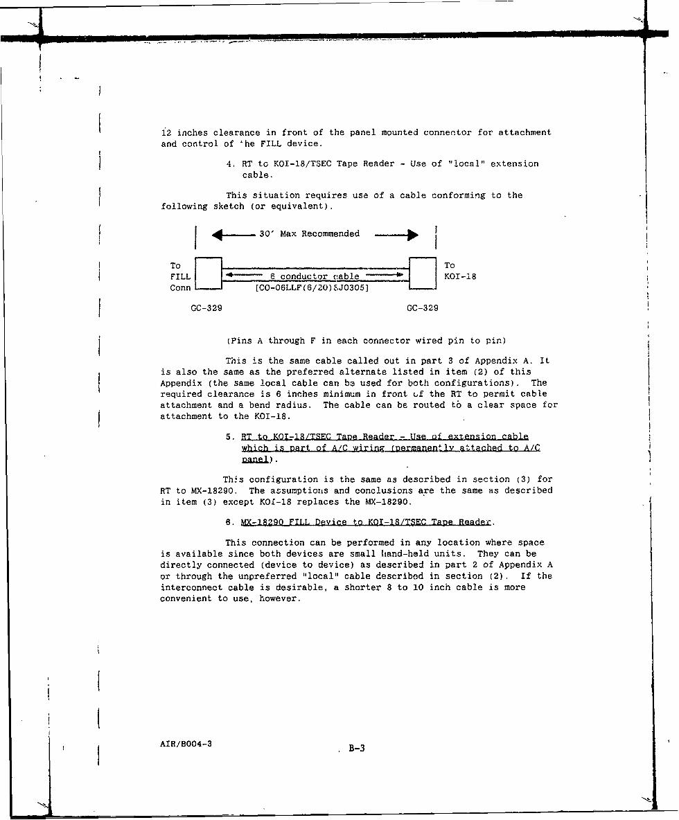
12 inches clearance in front of the panel mounted connector for attachment
and control of 'he FILL device.
4. RT to KOI-18/TSEC Tape Reader - Use of "local" extensioncable.
This situation requires use of a cable conforming to thefollowing sketch (or equivalent).
I 4.~,_ 30' Max Recommended
To ToFILL - 6 conductor cable KOI-18
Conn [CO-06LLF(6/20) SJ0305]
GC-329 GC-329
(Pins A through F in each connector wired pin to pin)
This is the same cable called out in part 3 of Appendix A. Itis also the same as the preferred alternate listed in item (2) of thisAppendix (the same local cable can be used for both configurations). Therequired clearance is 6 inches minimum in front (,f the RT to permit cableattachment and a bend radius. The cable can be routed tb a clear space forattachment to the KOI-18.
5. RT to KOI,18/TSEC Tane Reader - Use of extension cablewhich is part of A/C wiring (nermanentl attached to A/Cpanel).
This configuration is the same as described in section (3) forRT to MX-18290. The assumptions and conclusions are the same as describedin item (3) except KOI-18 replaces the MX-18290.
6. MX-1R290 FILL Device to KOI-18/TSEC Tane Reader.
This connection can be performed in any location where spaceis available since both devices are small hand-held units. They can bedirectly connected (device to device) as described in part 2 of Appendix Aor through the unpreferred "local" cable described in section (2). If theinterconnect cable is desirable, a shorter 8 to 10 inch cable is moreconvenient to use, however.
AIR/B004-3 B-3

STANDARDIZATION DOCUMENT IMPROVEMENT PROPOSAL(See Instructions - Reverse Side)
1. DOCUMENT NUMBER " DOCUMENT TITLE
3U NAME OF SUBMITTING ORGANIZATION S, TYPE OF ORGANIZATION (Mark one)
j] VENDOR
1 USE R
b. ADDRESS (Street, City, State, ZIP Code) MANUFACTURER
"E OTHER (Specify),
5. PROBLEM AREAS
4. Paragraph Number and Wording:
b. Recommended Wording:
c. Reason/Rationale for Recommendation.
Z
6. REMARKS
7a. NAME OF SUBMITTER (Last. First. MI) - Optional b. WORK TELEPHONE NUMBER rinclude Area
Code) - Optional
c. MAILING ADDRESS (Street, City. State. ZIP Code) - Optional 8. DATE OF SUBMISSION 'YYMMDD)
FORM PREVIOUS EDITION IS OBSOLETE.82DO MAR 1426