ad-a032 966 effects of strain rate in … · effects of strain rate in consolidated-undrained...
TRANSCRIPT
U.S. DEPARTMENT OF COMME•CENatlul Tedicah Imlfimha $sl
AD-A032 966
EFFECTS OF STRAIN RATE IN CONSOLIDATED-UNDRAINED
TRIAXIAL COMPRESSION TESTS OF COHESIVE SOILSREPORT 1. VICKSBURG SILTY CLAY (CL)
ARMY ENGINEER WATERWAYS EXPERIMENT STATION,
VICKSBURG, MISSISSIPPI
FEBRUARY 1970
I iI i
-- AF
F t C) MUn S.7f4 Ut
OF STRA -h RATE IN
tcO OIPMPRESV lfTS COF OOMUWE US
V WCKSJS SMPTY Oanf M2by71
It F. Spoil$. Dow at
-44
W-ki
4MUV c rr 4EVIO

Dssvýtivrpo.whnno.---v-w -oemod Do-
'M~vfmdim, +isrepot tre ot ov-t-u~l a anOffcia
Dopa -wt ofO-eArmypa~ionuiV'sr.s,% esim-*
it to mtheor~ize ato -mot.
1he fKdn;tsrpr .r 'o ': osteAo nofc'
MISCSLLAHIOUS PAPER S.70.
EFFECTS OF STRAIN RATE INCONSOLIDATED- UNDRAINED TRIAXIAL
COMPRESSION TESTS OF COHESIVE SOILS
VICKSBURG SILTY CLAY (CL)
R. F. E"Wnai.W-ia, J.It C~omp~f
Fe96mei 1970
Upmmi by Offic, Chief oF Enginwm U. S. Army
4s~tdb U. &. Army E.-gmeer VSbwwfty Exp..W..On S&S&Ion, Vicksburg, M~suiuippi
Thi document has hon apmwd for POWI~ Wes md asob; Its dkMstributo is nlld
4 1
:I
THE CONTENTS OF THIS REPORT APE NOT TO BE
USED FOR ADVERTISING, RMLICATION, OR
PROMOTIONAL PURPOSES. CITATION OF TRADE
NAMES DOES NOT CONSTITUTE AN OFFICIAL EN-
DORSENKNT OR APPROVAL OF THE USE OF SUCH tCOMHFWTr XAL IRCIXCTS.
17
. i 70006
S. . . . . .1._
This investigation was conducted for the Office, Chief of Engineers ,
(OCE), by the U. S. Army Engineer Waterways Experiment Station (WES) under
"the Engineering Study Item ES 516, "Evaluation of Laboratory Equipment and I,-
Testing Procedures." The testing program was authorized by OCE first
indorsement dated 18 September 1967 to WIS letter dated 14 July 1967,
subject: Rate of Strain in F Triaxial Ccmpression Tests, ES 516.
The study was conducted by sessrs. R. F. Esquivel-Diaz and F. G. A. WT
Hess, Laboratory Research Section, Embankment and ?oundation Branch, Soils
Division, under the direct supervision of Mr. B. N. Maclver, Chief, Labora-
tory Research Section, and under the gcneral supervisi=n of Mr. J. R.Compton, Chief, Embankment and Foundation Branch, And Mbesrs. W. J. Turn-
bull and A. A. Maxwell, Chief and Assistant Chief, respectively, Soils
Division. This report was prepared by Messrs. Esquivel-Diaz and Compton.
COL Levi A. Brown, CE, was Director of WES during preparation and
publication of this report. Mr. F. R. Brown was Technical Director.
v)
V_________________L -
- Q I-. 4 -k -
Contents
Foreword................... .............. ......................... v
Conversion Factors, British to !.btric Units of M~easurement .... ix
Simeary ............................... . . .. . . .* . . ..... ...... ...... ......... xi
Introduction........... .................................................... 1
Description of Equipment....... . . . . . ..6...........................2
Prep -.ration of Specimens, Testing Procedures, and Test Results ... 3
Compaction ......... . . . . . . ......................
Saturation and consolidation prcdures . ...................... . +Test resul1ts.... ... . .. .. .. .. . . . . . ..... .. .. ...........
Conclusions . . .. .. . ............... . . . . . . . . . . . .8
VFigs. 1-19
Tables 1-3
-A!
vii
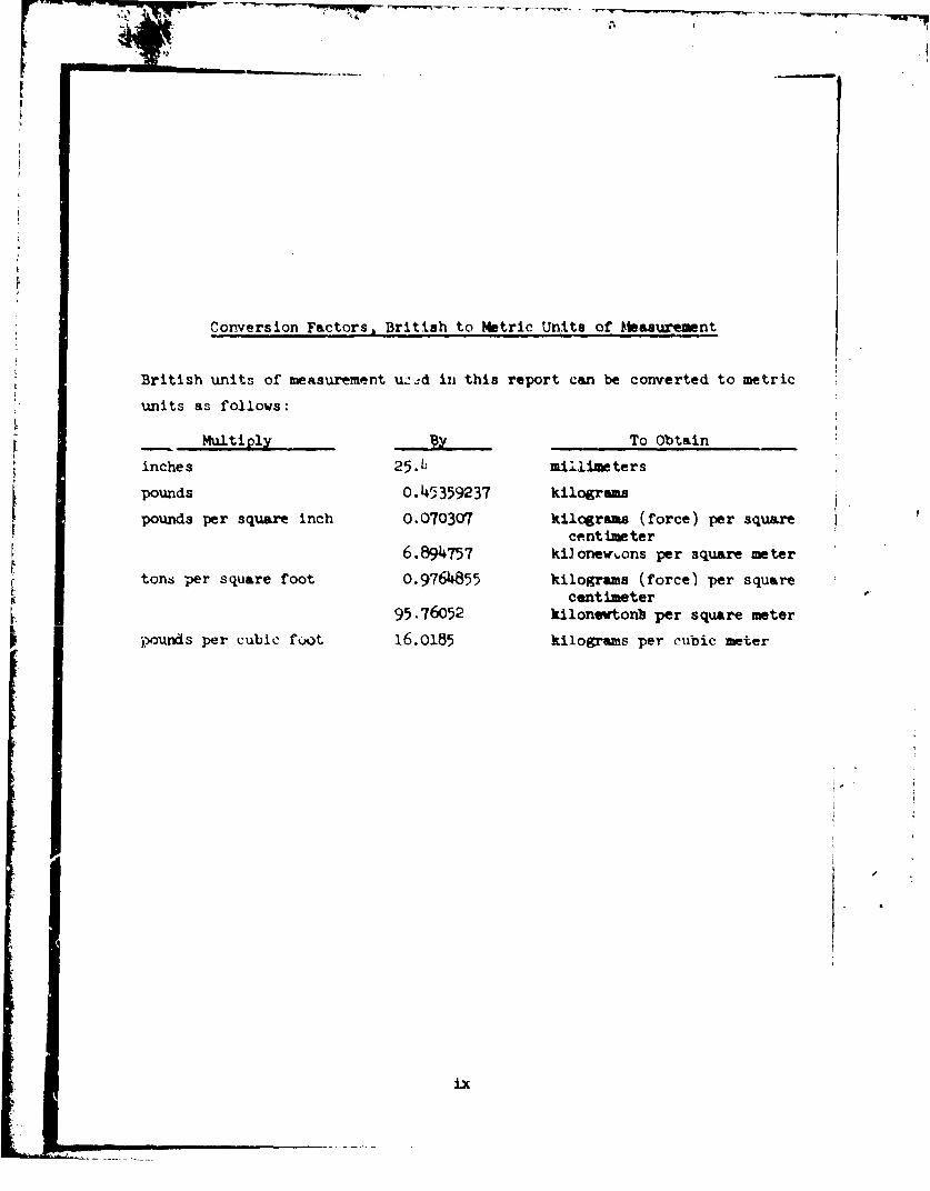
Conversion Factors, British to Metric Umits of Measurement
British units of measurement uLd in this report can be converted to metric
units as follows:
Multiply To Obtain
inches 25.L, millimeters
pounds 0. 4 5359237 kilograms
pounds per square inch 0.070307 kilograms (force) per squarecentimeter
6.894757 kilonew.ons per square meter
tons per square foot 0.9764855 kilograms (force) per squarecentimeter
95.76052 kilonewtonb per square meter
pounds per cubic foot 16.0185 kilograms per cubic meter
ix
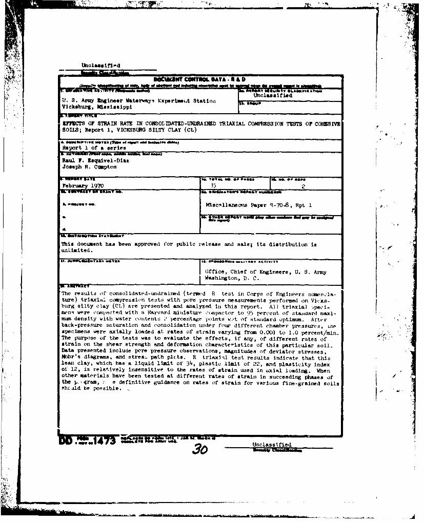
The results of consciidated-undzained (termed R test in Corps ofEngineers nomenclature) triaxial compression tests with pore pressure meas-urrments performed on Vicksburg silty clay (CL) are presented and analyzedin this report. All triaxial specimens were ccipacted with a Harvardminiature comactor to 95 percent of standard maximum density with watercontents 2 percentage points wet of standard optimum. After back-pressuresaturation and consolidation under four different chamber pressures, thespecimens were axially loaded at rates of strain varying frum 0.001 to1.0 percent/min. The purpose of the tests was to evaluate the effects, ifany, of different rates of strain Ln the shear strength and deformationcharacteristics of this particular soil. Data presented include pore pres-sure observations, magnitudes of deviator stresses, Mohr's diagrams, andstress path plots.
R triaxial test results indicate that this lean clay, which has aliquid limit of 34, plastic limit of 22, and plasticity index of 12, isrelatively insensitive to the rates of strain used in axial loading. When
other materials have been tested at different rates of strain in succeedingphases of the program, more definitive guidance on rates of strain forvarious fine-grained soils should be possible.
IX
xi
7fEMCTS OF STPAIN RATE IN COMIOLIDATI-UNDRAItIED TRIAX .LCO#'MSSI0N T&STS O? C2I2SIVIC SOILS
VICKSBURG SILTY CLAY (CL)
Intromuction
1. The present practice of the Corps of Engineers, as set forth in
EM l11O-2-19O6,* is to perform the consolidated-undrained triaxial com- . .
pression test, termed R tLest in Corp: of Engineers nomenclature, by first
completely 4aturatiic each of at least three identical soil specimens and
isotropically consolidating each specimen under a different effective pres-
sure. Then drainage connections to the specimen are closed and the speci- :
men is compressed to at least 15 percent axial strain. When it is desiredto determine only total stresses frcum the test, pore water pressures devel- 5"
oped during shear are not measured in routine testing. '.,2. Since R triaxial tests are time-consuming and expensive, it is
highly desirable that procedures used by the Division laboratories be as
economical as possible. An important element of the testing procedure is ' -
the time to failure or duration of the axial loading phase to the maximum
deviator stress. Currently, the time to failure is specified to be between
60 and 120 mn for cohecive soil. For tests in which it is desiri d to de-
velop stress-strain curves to 15 percent strain and where maximum deviator
stress is reached at low strains, the present procedure is time-consuming.
For example, if a constant strain rate is used during s2-&r and maximumdev i ator stress oc curs at 3 percent strain , s c~ l • a p e r h a e
for 120 min to reach this peak stress. If the test is carried to 15
perc'int strain, about 8 hr more would be required to complete the test.
The purpose of this investigation is to determine the rate of strain in theR test that will give the lowest value for maximum deviator stress so that •"••.
the most conservative total stress envelope can be developed.Department of the Army, Office, Chief of Engineers, "Engineering andDesign: Laboratory Svils Testing," Engineer Manual EM 1110-2-1906,
10 May 1965, Washington, D. C.
3. R triaxtal compression tests were performed by the U. S. Army
Engineer Waterwaye Experiment Station (WES) soils laboratory on specimens
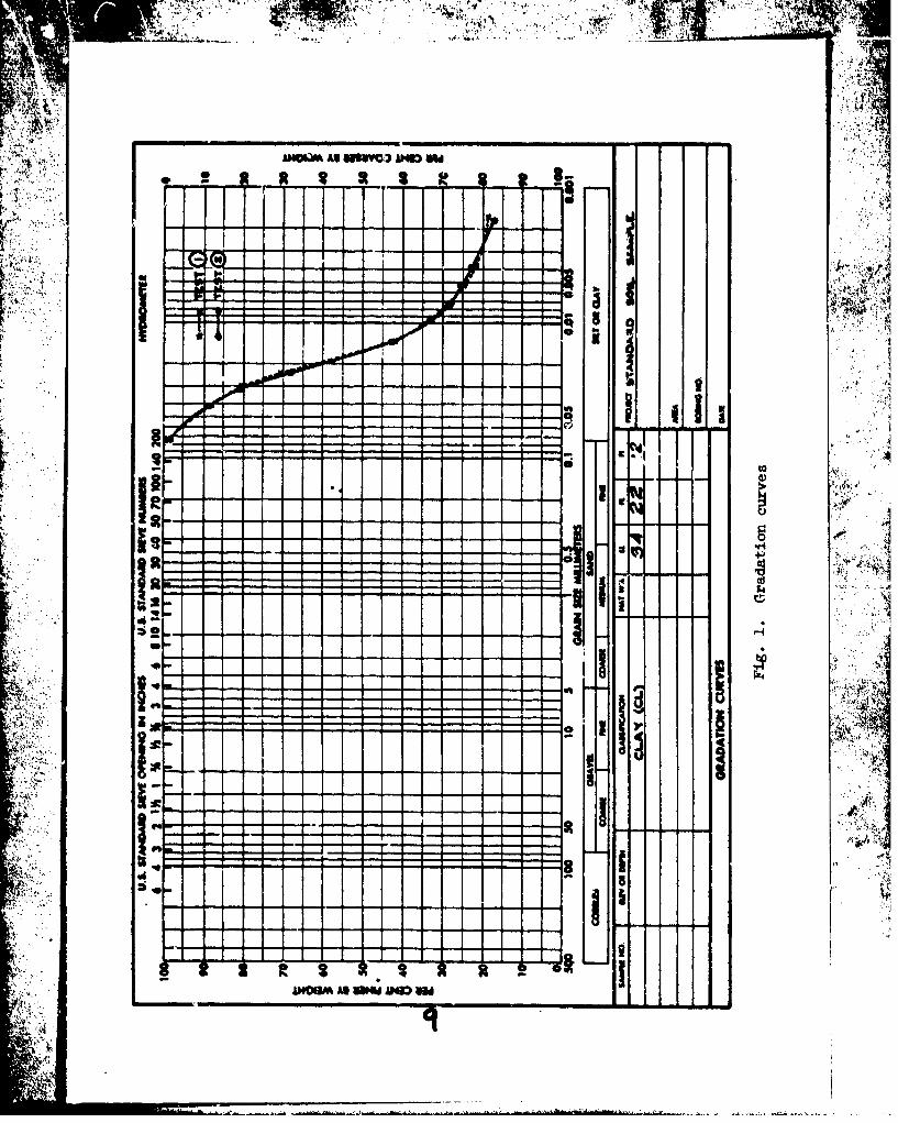
of Vicksburg silty clay (CL) standard soil.* Average Atterberg limits oi
the material based on previous standard soil sample tests were: liquid
limit, 34; plastic limit, 22; plasticity index, 12.*-* Average npecific
gravity was 2.68; percent. finer by weight than 2 microns averaged 18.
Gradation curves are presented in fig. 1.
4. Assembly and calibration of equipment were begun in October 1()67,
and the test program was accomplished during the period December 1967
through April 1968. Specimens were 1.4 in.t in diameter by 3 in. high, and
were compacted by the Har ard miniature compaction procedure to 95 percent
of standard maximum dry density at 2 percent above standard optimum water
content. Specimens were fully saturated by back pressure and consolidated
under pressures of 0.5, 1.5, 3.0, and 5.0 taf. Under each consolidation
pressure, specimens were sheared undrained at rates of strain of 1.0, 0.5,0.1, 0.01, and 0.001 percent/min until a maximum axial strain of 20 percent
was reached. Pore water pressures were measured during shear. After
shear, each specimen was cut horizontally into seven slices to determine
4-1- A4 ý*41to of the fl-al ctent.
Description of Equipment
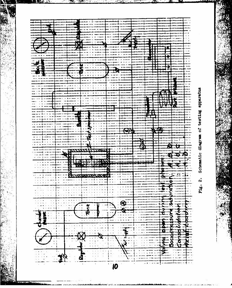
5. A schematic diagram of the testing apparatus is shown in fig. 2.
The triaxial chambers with specimen bases and caps and axial loading pis-
tons were those used regularly in the WES Soils Laboratory for Division
soil testlng.tt The confining pressure was applied by using water as the
chamber fluid, pressurized with compressed air, and measured with
* At this writing, a similar testing program is being initiated onstandard CH soil sample (Vicksburg buckshot clay).W. E. Strohm, Jr., "Preliminary Analysis of Results of Division Labora-
tory Tests on Standard Soil Samples," Miscellaneous Paper No. 3-813, Apr1966, U. S. Army Engineer Waterways Experiment Station, CE, Vicksburg,Miss.
t A table of factors for converting British units of measurement tometric units is presented on page ix.
"1t Op. cit., EM 1110-2-1906, Appendix X, Fig. 2.
2
calibrated Bourdon gages having a capacity of 200 psig. The air pressure
was controlled with pressure regulators.
6. Back pressure for saturation was applied with compressed air act-
ing on a colimn of watr Inside a calibrated burette. Air pressure was
controll-d with a pressur, regulator and measured with calibrated Bourdon
gages. 'he pore wewer pressure was measured at the base of the specimen,
using 3tatham presevre transducers with a rated capacity of 250 psi.
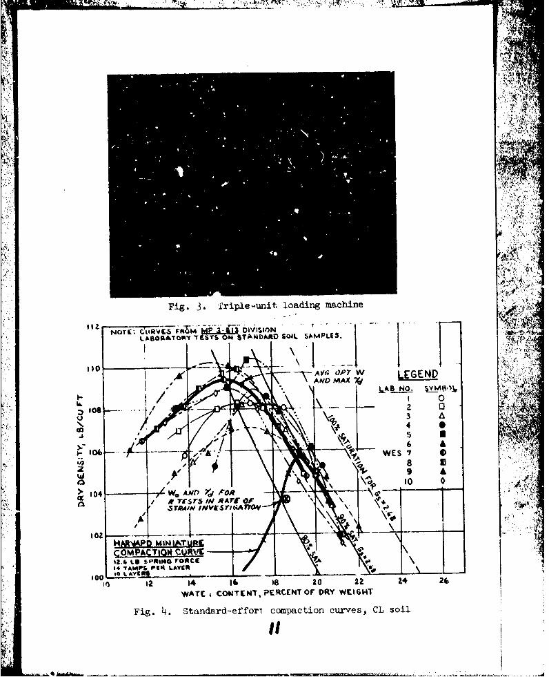
7. A triple-unit loading machine (fig. 3) was used to ahear the
specimens. The load was ipplied through a worm Jack operated by an elec-
tric motor with the piston of the triaxial chamber reacting against the
load cell, Each of the three load cells, made by Transducers, Inc., had a
rated capacity of 200 lb. Rate of strain was controlled wit'i a Zero-Max
speed reducer. For the two lowest rates of strair., a Boston V113 worm-gear
speed reducer, 20:1, was attached to the Zero-Max speed reducer. Change in
height of the specimens during shear was measured with a rectilinear
potentiometer (CIC) fixed to one of the loadJ.ng units.
8. A Mosley Autograf Model 7100A single-point strip chart recorder
was used to record the pore water pressure during the saturation phase.
Load, vertical displacement, and pore pressure measurements during axial
loading were recorded with a Westronics, Inc., Model RM11B strip chart
recorder with 24 channels. To operate the recorders, two CEC bridge-
balance units, type 8-108, were used with a regulated power supply, Model
40P4llFM, from Lambda Electronics Corporation.
Preparation of Specimens, Testing Procedures, and Test Results
Compaction
9. The optimum water content and maximum dry density of standard
soil sample CL, based on standard compaction tests by various Division
laboratorie;, were 16.6 percent and 109.2 pcf, respectively.* Fcr the rate
of strain tests, the desired compaction conditions were: water content
2 percentage points above optimum (18.6 percent) and a density equal to
* Strohm, op. cit.
3
"M~
95 percent of maximum dry density (103.7 Pca); see fig. K As shown in•
table 2, the actual initial compacted density of the teat specimens ranged.
from 103.4 to 104.0 pcf and the water content ranged from 18.2 to
19.0 percent. 44.f-
10. Sufficient soil to compact a single specimen was mixed with
water to attain the desired water content; by trial, it was iouia that ,::
about 0.8 percent more had to be added because of loss of moisture dur-'I l
ing processing and compacting. After the soil was thoroughly mi•xed in the
humid room, it was placed in an airtight glass jar to cure in the humid
room for a minimum period of 24 hr. Compaction was accomplished with a
Harvard miniature compactor, using a compaction rod with 1/2-In.-diam bear-
ing surface. The rod was provided with a spring that gave a compaction
force of about 12.6 lb when the spring was compressed..
11. All specimens were compacted in the humid room in 10 layers hay-
ing approximately the s'zue amount of material in each layer. By trial, it
was found that the desired dry unit weight could be obtained by using
14 tamps per layer. After the specimen was compacted and found to meet the 4,. "
desired compaction conditions, it was immediately set up in the triaxial ''.
chamber using two standard rubber membranes separated by a coat of silicone !:N
grease. No filter paper strips were used on the sides of the specimens.
The membranes were sealed using two O-rings at each end to fasten them Lo
the base and cap.
"Saturation and con-solidation procedures
12. Specimen setu_•u. In tests Ri through R4, the specimens were
allowed to remain overnight with no chamber pressure applied before com-
mencirn saturation the following day. Check test R4a in which a small .
chamber pressure was ma.' ;ained overnight showed results similar to com-
panion test R4, indica .. ng that ro change took place during the period
without chamber pressure. All other test specimens were subjected to 2-psi
'chamber pressure immediately after setting up in the triaxial chamber, and ..
the back-pressure saturation procedure was generally initiated shortly
thereafter.
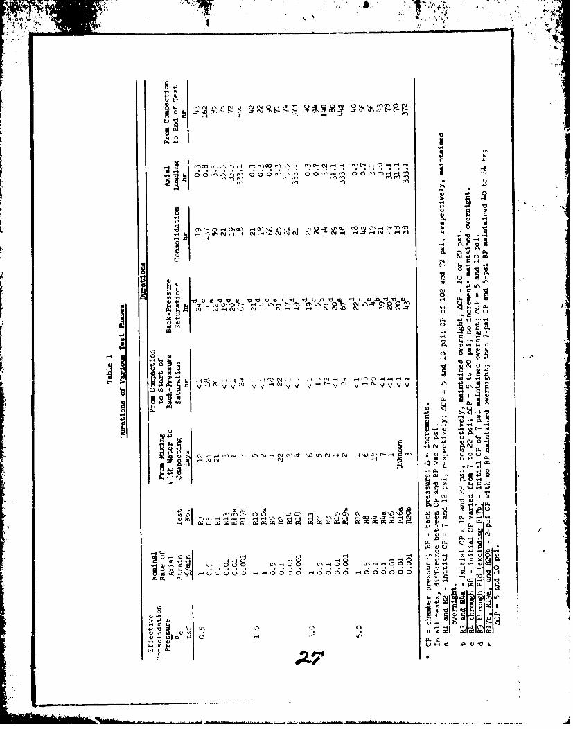
13. Specimen saturation. As indicated by the footnotes in table 1,
4
. ,.. ,
there were some variations in the back-pressure saturation procedure used
in the var: us tests, particularly in the initial tests. In all tests ex-
cept R1 through 1I+, a chamber pressure of 2 psi was imposed initially, and
burette readings were made until equilibrium was reached. Following this,
the chamber pressure was increased, generally to 7 psi, with a simultaneous
application of 5-psi back pressure. In all subsequent applications of
chamber and back-pressure increments, the difference between the chamber
pressure and the back pres iure was maintained at 2 psi. The most efficient
procedure with the least demands on operator surveillance was to allow the
initial chamber pressure nd back pressure to be maintained on the specimen
overnight, following which the chamber and back-pressure increments were
applied at intervals of 10 to 15 min. During the saturation process, the
response of the pore pressure transducer was recorded. Following back-
pressure saturation, valve B (fig. 2) was closed, the vertical dial indi.-
cator was read, and the specimen was ready for consolidation under the
desired pressure.
14. Specimen consolidation. With valves B and C closed (see fig. 2), I
the ch,.mber pre-,-sure was increased so that the difference between the chain-
ber pressure and back pressure was equal to the desired effcctive coysolide-
tion pressure, and the pore pressure was observed to verify the comple ;e-
ness of the saturation process. Then, valves B ani C were opened, and bu-
rette and dial indicator readings were made at time intervals. When con-
solidation was completed, valve B was closed and the specimen was ready for
&xial loading. It was observed, after consolidating a few specimens under
different lateral pressures, that primary consolidation was completed about
2 hr after the consolidation process started, and that the CL soil showed
no important secondery consolidation. For this reason, the consolidation
phase was ended when 24 hr had elapsed after the beginning of consolida-
tion. Duration of the various test phases is shown in table 1.
Test results
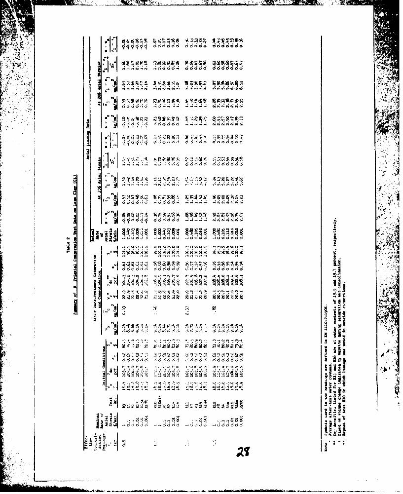
15. Table 2 summarizes the triaxial compression test data, shoving
not only the axial loading data but also initial specimen conditions and
specimen conditions after back-pressure saturation and consolidation. The
tests are grouped in this table according to the chamber pressure used.
5
W ,+.4.F-
The before- and after-test specimen conditions will be discussed first,
following which the shear test data will be discussed.
16. Specimen conditions. Initial water contents and compacted dry
denilties for the tests listed in table 2 habd verage -•l.us of 18.6 per-
I cent and 103.7 pcf, respectively, which were exactly those desired. The
greatest deviation among all specimenr was +0.4 percent for the water con-
tent and about +0.4 pcf fir the density. It is to be noted that meax spec-
imens were compacted and rejected bect-use their water content ud/or den-
sity were not close to th, desired values. It is also to be noted that thewater content of 18.6 percent for the shear test specimenz is scmewhat dryof the optimum water content for the compaction effort used to obtain the
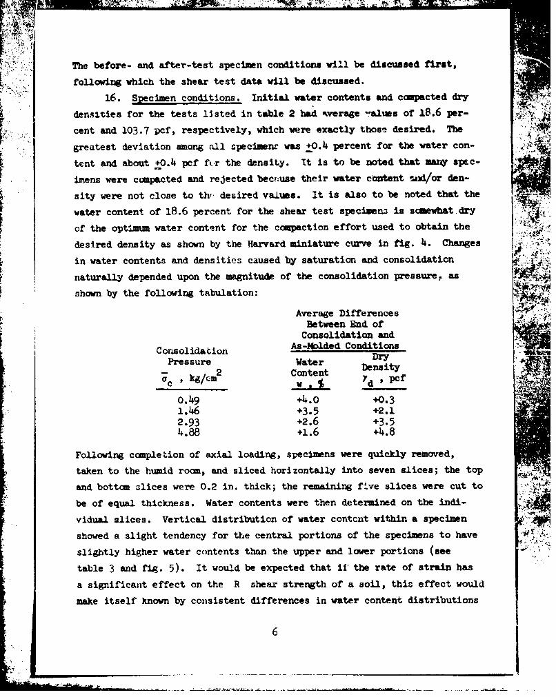
desired density as shown by the Harv&rd miniature curve in fig. 4. Changes
in water contents and densities caused by saturation and consolidation
naturally depended upon the magnitude of the consolidation pressure, as
shown by the following tabulation:
Average Differences .?i
Between End ofConsolidation and
C onsolida ion As-Molded ConditionsPressure Water
- 2 Contentc k 7 d ' pcf
0.49 +4.0 +0.31.46 +3.5 +2.12.93 +2.6 +3.54.88 +1.6 +4.8
Following completion of axial loading, specimens were quickly removed,
taken to the humid roan, and sliced horizontally into seven slices; the top
and bottom slices were 0.2 in. thick; the remaining five slices were cut to
be of equal thickness. Water contents were then determined on the indi-
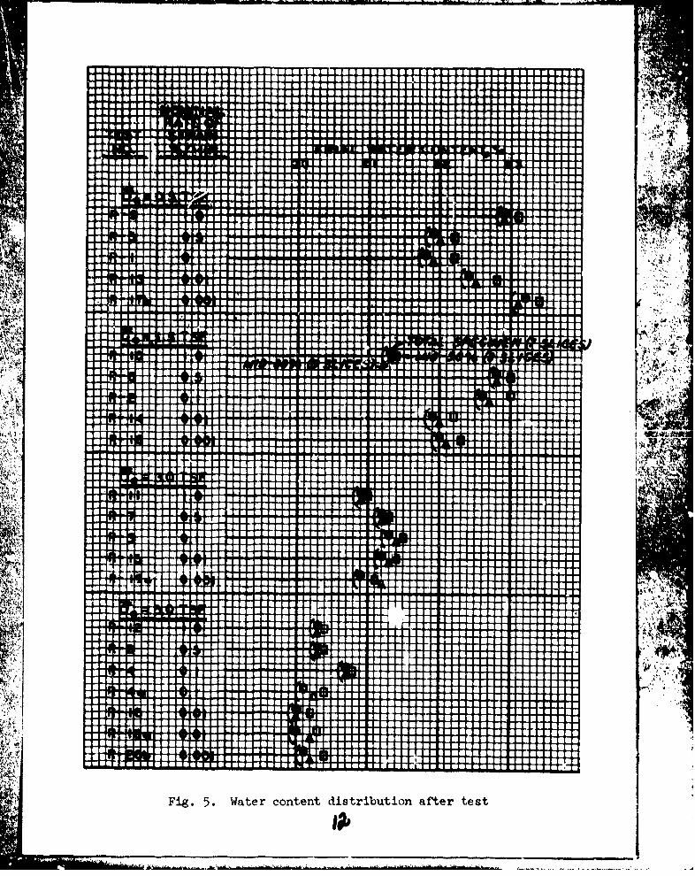
vidual slices. Vertical distributicn of water coratcnt within a specimen
showed a slight tendency for the central portions of the specimens to have
slightly higher water contents than the upper and lower portions (see "
table 3 and fig. 5). It would be expected that ii' the rate of strain has
a significai•t effect on the R shear strength of a soil, this effect would
make itself known by consistent differences in water content distributions
6 1
vitbin specimens consolicated under the same pressure, but axially loaded
at elfftrent ruteu of strain. However, table 3 indicates that there is no
pattern of variation of the water content determined after shear with dif-
ferent rates of strain for tests with the same chamber preusures; there-
fore, from this standpuint, it is indicated that this CL soil is relatively
insensitive to the rate of axial strain.
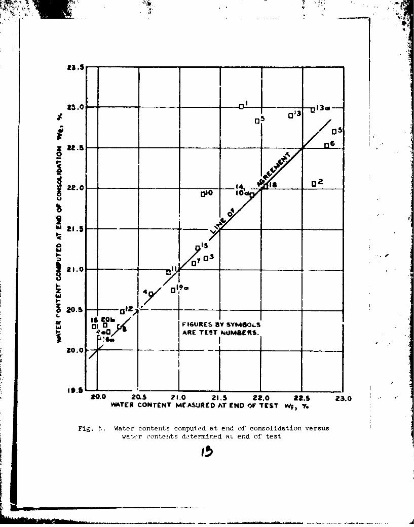
17. It is of interest to Qosparc the water contents detprminnd
directly at the end of test with water contents c,:unputed for the after-
consolidation conditions (using the initial water contents and water con-
tent changes observed during saturation and consolidatir'n as indicated by
the burette). Fig. 6 shows generally close agreeme.ft between water con-
tents computed by the method described in table 3 and the water contents
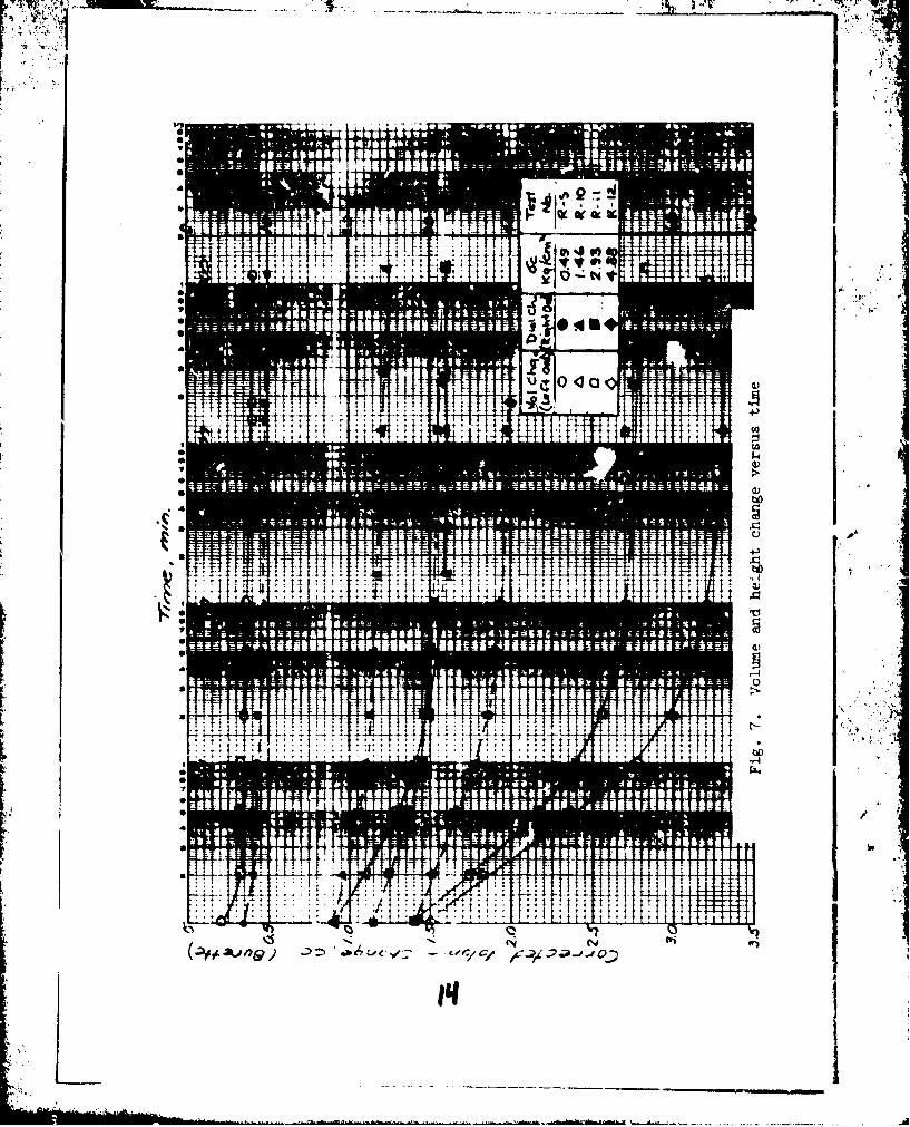
determined at the end of the tests. Plots of volume changes (as indicated
by the burette) and of changes in specimen height (as indicated by the dial
gage) during consolidation are shown for four tests under different consol-
idation pressures in fig. 7.
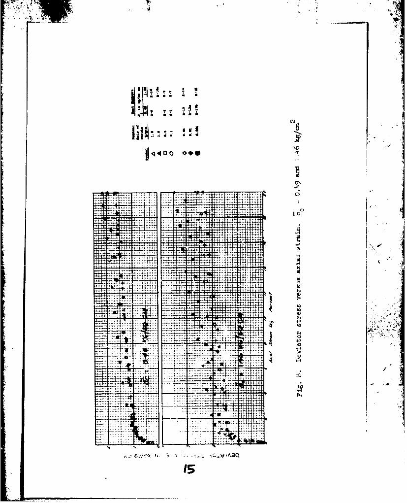
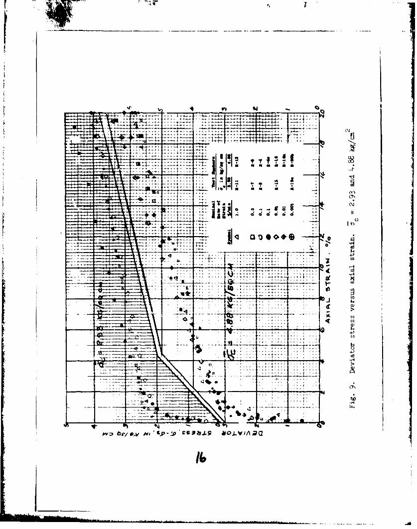
18. Shear strength and pore pressure data. Plots of deviator stress
versus axial strain with test data grouped under each of the four confining
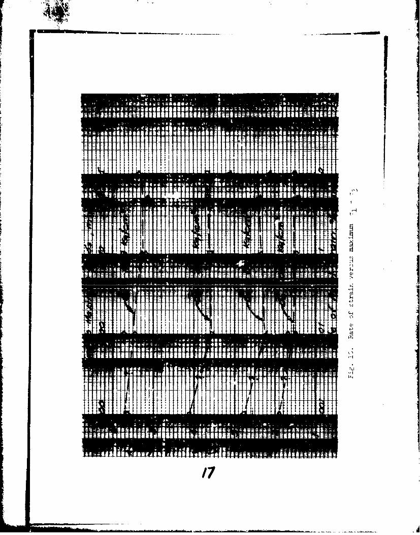
pressures used in '.he test program are shown in figs. 8 and 9. Fig. 10 is
a plot of maximiuu deviator stress versus rate of strain. Since deviator
stresses did not peak before 20 percent axial strain, the deviator stress
at an axial straii. of 15 percent is reported as maxim=n deviator stress as,
prescribed in EM 1110-2-1906. Thus, fig. 10 also presents maximum deviator A
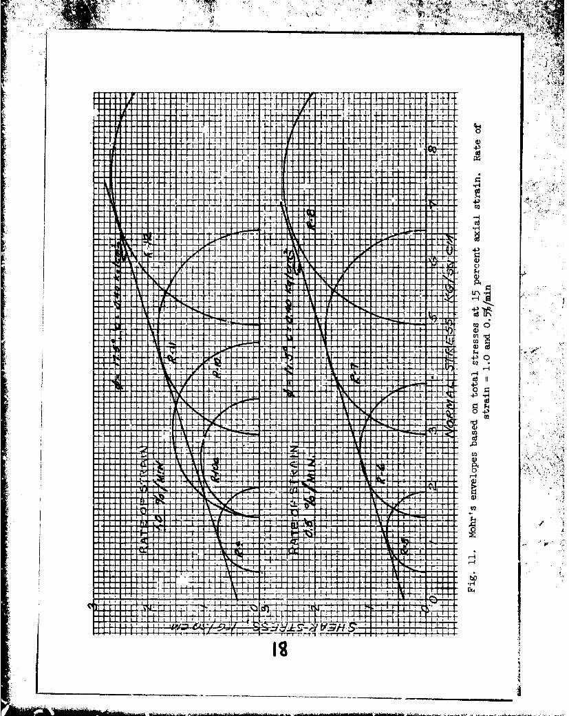
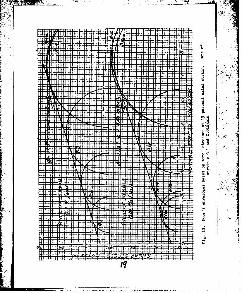
stress versus time to 15 percent axial strain. The Mohr's diagrams in figs. N,
U and 12, in which test data are grouped by rate of strain, show that for
rates of strain from 0.01 to 1.0 percent/ain, a shear strength, based on2total stresses, of % = 17.5 deg and c = 0.40 kg/cm fits all four plots
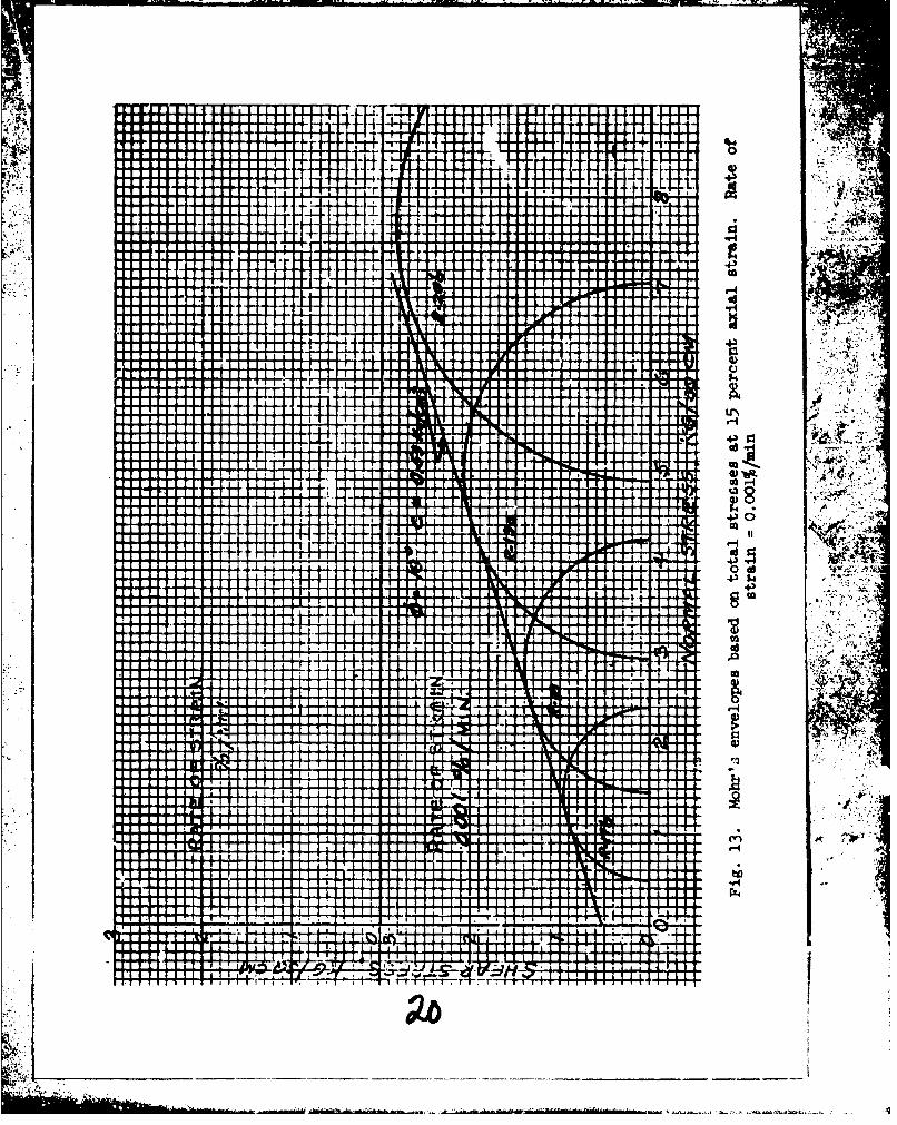
very well. The shear strength for the tests at rate of strain of 0.001 per-
cent/min (fig. 13) is somewhat higher (• 18 deg, c = 0.53 kg/cm2 )
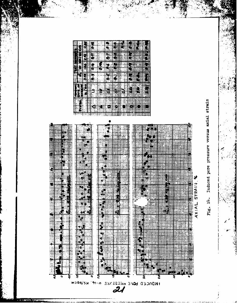
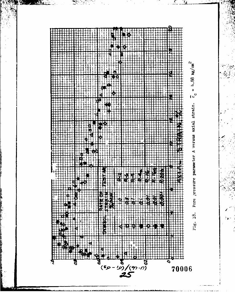
19. The plot of induced pore pressure versus axial strain in fig. 124shows no discernible effect of rate of strain on the pore pressures induced
by axial loading based on measurements taken at the base of the specimen.U - 0
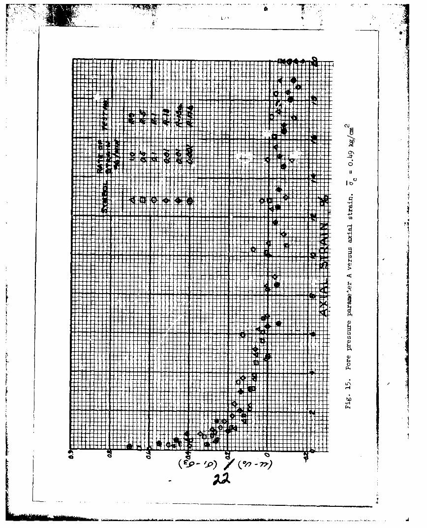
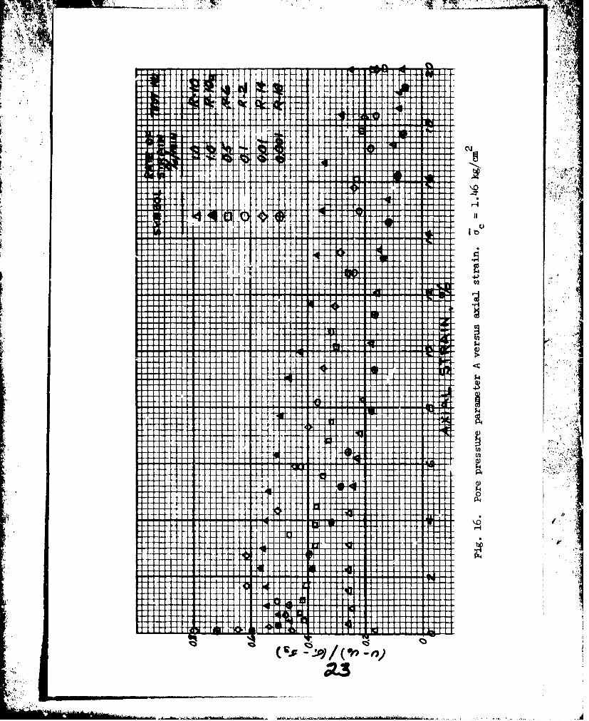
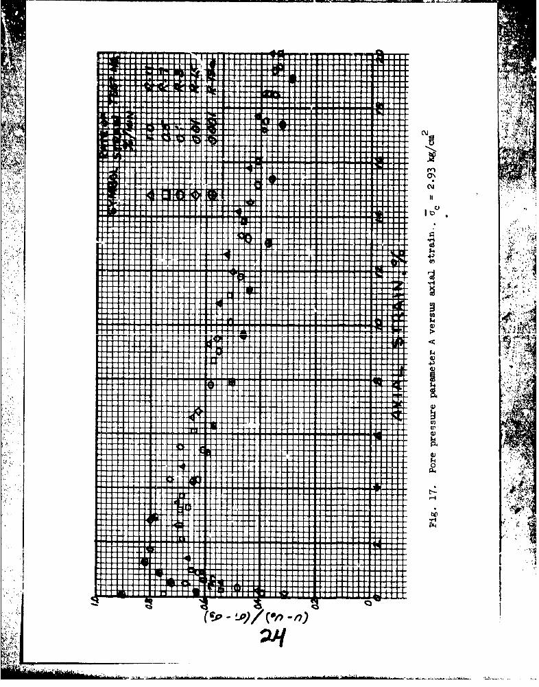
Plots were made of pore pressure parameter A = versus axial1 a3
7
ý.A9
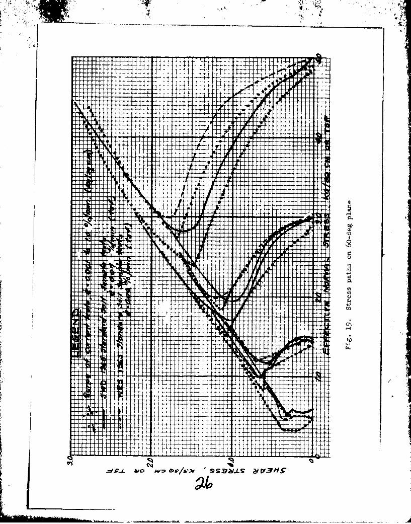
strain, and these are presented in figs. 15-18. Fig. 19 shows the ranges
of stress paths for the current tests in which the rate of strain was
varied from 0.001 t: 1.0 percent/min and also shows stress paths of the R
tests by the U. S. Army Engineer Division, Southwestern (SWD), and by WTS
in the 1965 standard soil sample test program on the same material, using
rates of strain of 0.06 to 0.07 percent/min.
Conclusions
2C Results of this test program indicate that this Vicksburg lean
clay compacted at a water content 2 percent wet of optimum and to P dry
density of 95 percent of standard Proctor maximim dry density is only
slightly sensitive to rates of axial strain in the R test. Under effec-2tive confining pressures of 0.49, 1.46, 2.93, and 4.88 kg/cm , rates of
strain ranging from 0.5 to 0.01 percent/min gave the lowest values of maxi-
mum deviator stress. However, it appears that for this material at this
condition, axial loading might be as fast as 1 percent of axial strain per
minute without appreciably affecting the total stress results. When other
materials have been tested at different rates of strain in succeeding
phases of tLe program, more definitive gaidance on rates of strain for
various fine-grained soils should be possible.
8
, A.
L -- -it
I -wf As NamYV M4UW IN
~~ A".~fr -
Nv
P44
.. . . .P
4 -0
N &
41".
A,
Fig. 3. I'riple -unit loading machine
LABORATORY TESTS ON STANDARD SOIL 5AMPLE3.
VA V6 X OR TW LEGENDLAS NO. jyLmo-)~
Jo 034
6 'At
UW~ES 7
o0 0C> 14 -- W.ADY rO
/aiSrsM N~fRATFV"
HiT\A'p MIN Sr"AA7Ov
WATE. CON4TENT,PERCENT OF DRY WE)IGHT
Fig. 4.Standard-efforl compaction curves, CL soil
t T,.
It,
L A6
Fig.~~~~~~~~~~ 5. WtrcnetX1tiuinatrts
ass -0 -rl 1-
/05
2 21.5
04
U11
22. 14, 0'
o~~1 208 0 f'
€. IS L•Ob Fo •I rGURES SY SYMUO.SI.-O/a7' ARE TCE:T AiUMSCRS.
1) 6 . I
20.0 -- -- _ _ _
512.5 ~ 15 2.
0.0 2065 21.0 212. 22.0 202.S &0WATER CONTENT MCASURED AT END OF TEST Wf, I.
Fig. t,. Water contents computed at end of consolidation versuswater -'ontents determined aL end of test
I I ,
A~~~~~~ ......... _ __ __ __ __ _
INITXLt:
I a' ~ ~ L -- 1 1:- L4
~ V1 MRS
WO
.11131 1 19
ki~l? 4
- H-H
PI'
Ht Ti T++
A At,
I
* w -
__'ID
TV (d
*v~ ~~ -P Or ov Al V 1A2
AD2 ~ o'm o
rI - IIN-11 Fm
I I t tll I II 11-lH
17-
4**
'4-
Y43
I t
Ftt I',Jý1
Evil
fit
-+Hi4I
A- 9lA
4) W
943
InI
I i I r
I I t I I I I, I
w ill I
H4- HH
44,)
i, e
I T
7f++
42
ot4t
-jr>
I rII
I~ I f
C,,
F 1 -6 CY
4+4IFI I T
IT TUI
3a
IMI---- - ____
-4'-4
\II
J4.
IlT.4
5.4
L 1-
C'.'
rvj
t II
- - - - - - - -- - -
+t 4@ -t
. . . . . . .4-- - - - - - -4-
-41 N
F II
FT 1V
.4.
Ift A-
AT- -- I%.
C6
-4 P-4
On -n)70006
A"t
41
LIZ
44 I
id T'lik I
IT U3IýI
-LA
IQ-
L4)8
0
411
CO\ (1N ) H ~o~ ý'N-4 Ný I t'H H~Cl 0 4 r4
00 4-
01al
VI
C: IIwo~~~v N\ *f-
4
ýo N Cjr- 4ý4 C .0) CLj)
L)I ~\n't
+) ~ H~ j~IW. ~ *~
H- Ht - 4) \ . 4 1m N t C - H 4 ~ ýw 4 to)
. \Lr-4( -40 U''\0v v v v4000000 I v N v4 C' 0
COP
j~4I3
H -0~ ("H0W 44
00C.C.)
law
T. 4~I C?'?9 ; OCfOO ('; 00000 '000; 0000 4
i A. I,,I
ý4( tu ; C C 406a 0000 0000000
.' .4. . . . . .
'I 0 301 0 -300- N4.4- N N N 'NNN
1 00.. 40.00 001100 0000000
00000 0000 00 '
R3 la
000000 00000 0 000000N~kN
4. . . . . .4 . . .4.
- .4
000000 .0C0000 .0000 0000000
.8 -6 s..'4S 4'.4 .0. -6t A s 8& .
- 4 4 , ,,44 .444..4 .4. .414. 1.44.. .4
0 00 C .6 j 000 00ý l 0 0 0 C000 00 I"'4 040* ~ 0. >4'0041 40440 40404
0 )t' 44 4~4~4) ~ 4 444) 44~4,5~
'-.1 04
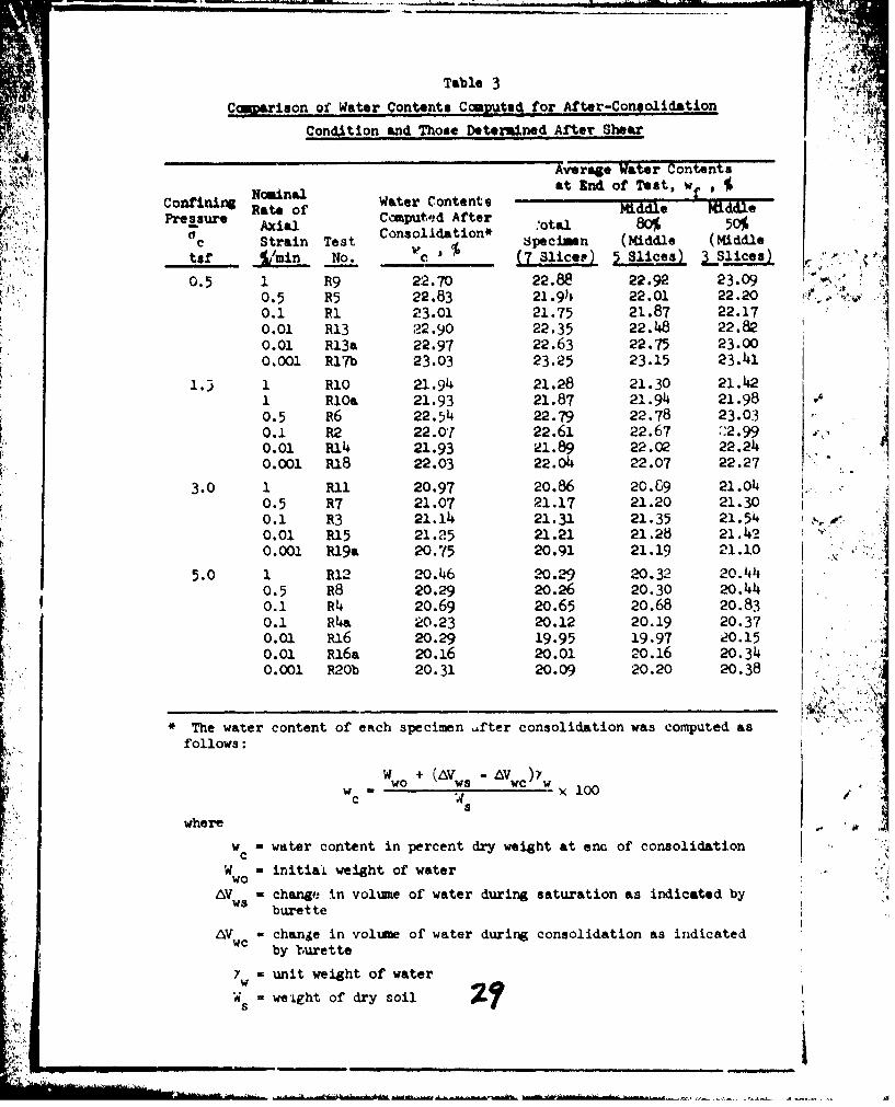
Table 3Cmarimson of Water Contents Cepiat.d for After-Consolidation
Condition and Those Detemined After Shear
Average Witer Contentsat End of Test, w
Ncainal Water Contents M.....Confining Rate of Middle MiddleR Ateal Comput'?d After .'otal 80% 50%
AxialConsolidation*c Strain Test Specimen (Middle (Middle
tsf %Lmin No. :' (7 Slicer) 5 Slices) LSlices)
0.5 1 R9 22.70 22.88 22.92 23.090.5 R5 22.83 21.919 22.01 22.20 ., .
0.1 R1 23.01 21.75 21.87 22.170.01 R13 22.90 22.35 22.48 22.820.01 R13a 22.97 22.63 22.75 23.000.001 Rl7b 23.03 23.25 23.15 23.41
1.3 1 R1o 21.94 21.28 21.30 21.421 RlOa 21.93 21.87 21.94 21.980.5 R6 22.54 22.79 22.78 23.03 '.40.1 R2 22.07 22.61 22.67 "2.990.01 R14 21.93 21.89 22.02 22.2410.001 R18 22.03 22.0o 22.07 22.27
3.0 1 Ru1 20.97 20.86 20.69 21.040.5 R7 21.07 21.17 21.20 21.30 t0.1 R3 21.14 21.31 21.35 21.54.0.01 R15 21.25 21.21 21.28 21.4?"0.001 R19a 20.75 20.91 21.19 21.10 ,N
5.0 1 R12 20.46 20.29 20.32 20.441.0.5 R8 20.29 20.26 20.30 20.440.1 R4+ 20.69 20.65 20.68 20.830.1 R4a 20.23 20.12 20.19 20.370.0 R16 20.29 19.95 19.97 20.150.01 Rl6a 20.16 20.01 20.16 20.34-0.001 R20b 20.31 20.09 20.20 20.38
The water content of each specimen "fter consolidation was computed asfollows:
w wo + (AV AVw ,w. =W 100
where ,
w - water content in percent dry weight at eno of consolidation
W initial weight of waterwoAV - change in volmne of water during saturation as indicated by
ws burette
AV - change in volume of water during consolidation as indicatedwc by burette
7 a unit weight of waterw
Ws - we-ight of dry soil
DCUV.NT COMMUO DATA. - a aD
Uncloassified
U. S. Army briineer Watoromyv Cxperimei~t Station I foWcksburg, Nislsissippi
IflECT OF STRAIN RATE INi CONSOL MATID -UMBRA INED TRIAXIAL CO#4FRSSION TESTS OF COIH5 lYESOILS; Report 1, VICKSBURG SILTY CLAY (CL)
Report 1 of a series_____________________
Raul Fr. loquivel-DiazJoseph R. Compton
FebrluAry 9190 35 OL O.C At
oftwoor ue liscmlaneoqus Paper q-70-8, Rpt. I
This document haa been approved Vor public release and sa~le; its distribution is
mumdenitywit waerconent 2 ercntae Ofict, Chiet of sta indard U.tim S. Aftmr
sTherainuonthe ohef csotrengthndre d(formatio chR te-stinCors of thgiser patclarsil.,aDta resentedxii icmpdesintuswh pore pressure osrainmeagniudemns pfeviaormdo trexssesbuhrg diycayrams, andsres. paeethdEn patalz. HtInx. teist repults l tindiate thateti_
lueansclay, which hase aotet liui limiteofa3e plansti liit oif 22,andarplastimity inder
ope1ieis wrelaxially insnatied ato rates of strain uaediin f om ia 0.00 dio.0 pe hentMnoTher matriplseo thae bntestsaoedalate diefferetrtes, of stainy odiffueredng rases ofstrae on thenr sha stefnitiv uian efonrmateo hrctrsis of stanfohaius paricu-arae soils
1Da be poesenedibclue. por prssr obevtos antdsfdvao tess
Mohr T '7'sdarmadse& path Jam e. R maxit tsreunlassInifated tatilen lywic hsa iui lmt f34,patclmto 2,adpatct ne
Uncleanifled
nIt RVwmon**I] T RI• V n~I
NO IIOTIL O
Cohesive soils
CompreMsion teats
Conaolidated-undrained tests
Pore pressure weaurement
Soil teats
Triaxial compression tests
Vicksburg silty clay
Uli
/ nlsil U