ad-a027 096 a technique for shipboard sonar … a technique for shipboard sonar echo simulation for...
TRANSCRIPT

U.S. DEPARTMENT OF COMMERCENational Technical Information Service
AD-A027 096
A TECHNIQUE FOR SHIPBOARD SONAR ECHO SIMULATION
FOR TRAINING
NAVAL TRAINING EQUIPMENT CENTER
JUNE 1976
4' I I -I
- ~ ~205070 ..
Technical Report: !4AYTRAEQUIPCEN IH-231
-C 1 A TECHNIQUE FOR SHIPBOARD SONARECHO SIMULATION FOR TRAINING "
Naval Traliing Equipment CenterOrlando,, Florida 32813Co
',\Y
Final Report for Period July 1972 - January 1974
I DoD Distribution Statement
Approved for public releme;distr4wuton unlmited.
PEPNODUCED BY
NATIONAL TECHNICALINFORMATION SERVICE
U • F •R %*[N1 OF COMMERCESPRINGF•ELD. VA. M'161

r-
Technical Report: NAVTRAEQUIPCEN IH-231
A TECHNIQUE FOR SHIPPOARD SONARECHO SIMJLATION FOR TRAINING
Herbert Berke
June 1976
GOVERNMENT RIGHTS IN DATA STATEMENT
Reproduction of this publication inwhole or in part is permitted for anypurpose of the United States Government
Approved:
M. ARONSONHead, Electronics and Acoustics Laboratory
Directo R erch and Technology Departm it
NAVAL TRAINING EQUIPMENT CENTERORLANDO, FLORIDA
32813
I

Unlasified_SECURITY CLASSIi:ICATION OF THIS PAGE (*%&i Dota Entet.d_
REPORT DOCUMENTATION PAGE READ INSTRUCTIONSREPORT DOAACES BEFORE COMPLETING FORM1. REPORT NUMBER GOVT ACCESION NO. 3. RECIPIENT'S CATALOG NUMBERS) NAVTRAEQUIPCEN IH-231
4. TITLE (and Subtitle) S. TYPE OF REPORT & PERIOD COVERED
A Technique for Shipboard Sonar Echo FinalSimulation Training July 1972 - January 1974
10. PERFORMING ORG. REPORT NUMBmER
7. AUTHOR(*) G. CONTRACT OR GRANT NUMBER(.)
Herbert Berke
9. PERFORMING ORGANIZATION NAME AND ADDRESS 10. PROGRAM ELEMCNT. PROJECT. TASKAREA A WORK UNIT NUMBERSDepartment of the Navy A
Naval Training Equipment Center NAVTRAEQUIPCEN Task No.Orlando, Florida 32813 1724/37211 ,. CONTROLLINC. OFFICE NAME AND ADDRESS 12 REPORT DATE
Naval Sea Systems Command June 1976Sonar Technology Office (06H13) M--NUMBER OF PAGES
Washington, D. C. 20360 5314. MONITORING AGENCY NAME & ADDRESS(If dilffrent from Conte 'lltn , Office) IS. SECURITY CLASS. (of t sle report)
Unclassified I4Se. DECL ASSI FI CATI ON/ OWN GRADING
SCHEDULE
16. DISTRIBUTION STATEMENT (of thli Report)
Approved for public release; distribution unlimited
17. DISTRIeUTION STATEMENT (of the abetract entered in Block 20. It different from Report)
1I. SUPPLEMEHTARY NOTES
19. KEY WORDS (Continue on reverew side If necessaey and Identify by block number)
Accustic DetectionDigital Delay Lines EchoesShift Registers Sonar Simulation
20 ABSTRACT (Continue on reverse aide If nec.essay and Identify by block rnmber)
A means for synthesizing echoes using a combination of analog and digitaltechniques for target classification training of shipboard ASW men wasneeded.
A study indicated that the echoes could be generated by using the lateststate-of-the-art methods and components. ~~BSUBJECT TO QMNI
DnD Io- 1473 EDITION OF I NOV GS6$ OBSOLETE UnclassifiedS/N 0102-014-6601 SECURITY CLASSIFICATION OF THIS PAGE (lWUn Date •Enft*)
I

Unclassified-LAIJHITY CLASSIFICATIO,., OF TPIbI V AvElWhw rsst. Ent.8.,dj
(Cont from Block 20)A system incorporating solid state components was designed and implementedto produce a synthetic sonar echo. The finalized research tool was thenevaluated at the Key West Fleet Sonar Training School and at the NavalTraining Equipment Center, Orlando. Installation of a prototype trainerin a Navy Sonar Training School is reconmnended. Training effectivenessstudies should be conducted in order to determine the full extent of trainingtransfer from the simulator to the real world situation. It is furtherrecommended that this study be continued to include the effects on the echosignal due to multipath propagation and reverberation. Methods should beinvestigated to feed the echo signal to the sonar set receiver processorinput on a non-programmed basis. This would in:lude additional electronicsor a mini-compuxer to solve target motion and position relative to own ship.
Unclassified
SECURITY CLASSIFICATION OF THIS PAGE('be, Dee& tnn'e• )

NAVTRAEQUIPCEN IH-231
PREFACE
Existing shipboard echo generators are not suitable for classificationtraining. A need has existed for means whereby shipboard operatortraining in active sonar target detection and classification coule beaccomplished. Such echo simulators are desirable for use in place ofmobile targets or submarines to track in training exercises, in decoydevices for misleading enemy antisubmarine measures, and in sherebasedsonar training devices. With this in mind, it was a principal objectof this task to provide a simulator utilizing a novel combination ofdigital and analog techniques to genetate a simulated echo. This simu-lated echo is a function of target characteristics, i.e., length,aspect angle, doppler frequency.
2

NAVTRAEQUIPCEN IH-231
TABLE OF CONTENTS
Section Page
T INTRODUCTION .................................. 5
II STATEMENT OF THE PROBLEM ..................... 5
Iii PROCEDURE ..................................... 6
IV S$NAR ECHO SIMULAIOR SYSTEM .................. 7
External Inputs ............................. 7
Panel Control ............. ................. 7
V SYSTEM ANALYSIS ............................... 8
Signal Flow ..................... ........... 8
VI PANEL CONTROLS ............................... 8
Aspect Angle ................................ 9
Velocity Control ............................ 10
Length Control .............................. 10
VII RANDOM ACCESS SOLID-STATE MEMORY (RAM) ....... 11
VIII RESULTS AND RECENDATIONS .................. 12
Appendix A, Parts List of Major Components .... 13
LIST OF TABLES
Read Only Memory No. 1 ...................... 14
Read Only Me-r ' "o. 2 ...................... 15
Read Only Memory No. 3 ...................
Read Oily Mcur ry INo. 4 ..................... 17
3

14AVTh.AEQuiPat, T1.1-2-,1
LIST OF ILUJSTnATIOGS
Figure Par -
1. System Block Diagram ........................................... 18
2. Timing Control Block Diagram .................................. 19
3. Front Panel .................................................... 20
4. Input Mixer/Oscillator .................................... 21
5. Low Pass Filter and Clock.............. .................... 22
6. Input Digitizing Circuit ....................................... 23
7. Aspect Angle Circuit ................................... ....... 24
8. One-Second Clock ......................................... 25
9. L cos G Control .......................................... 26
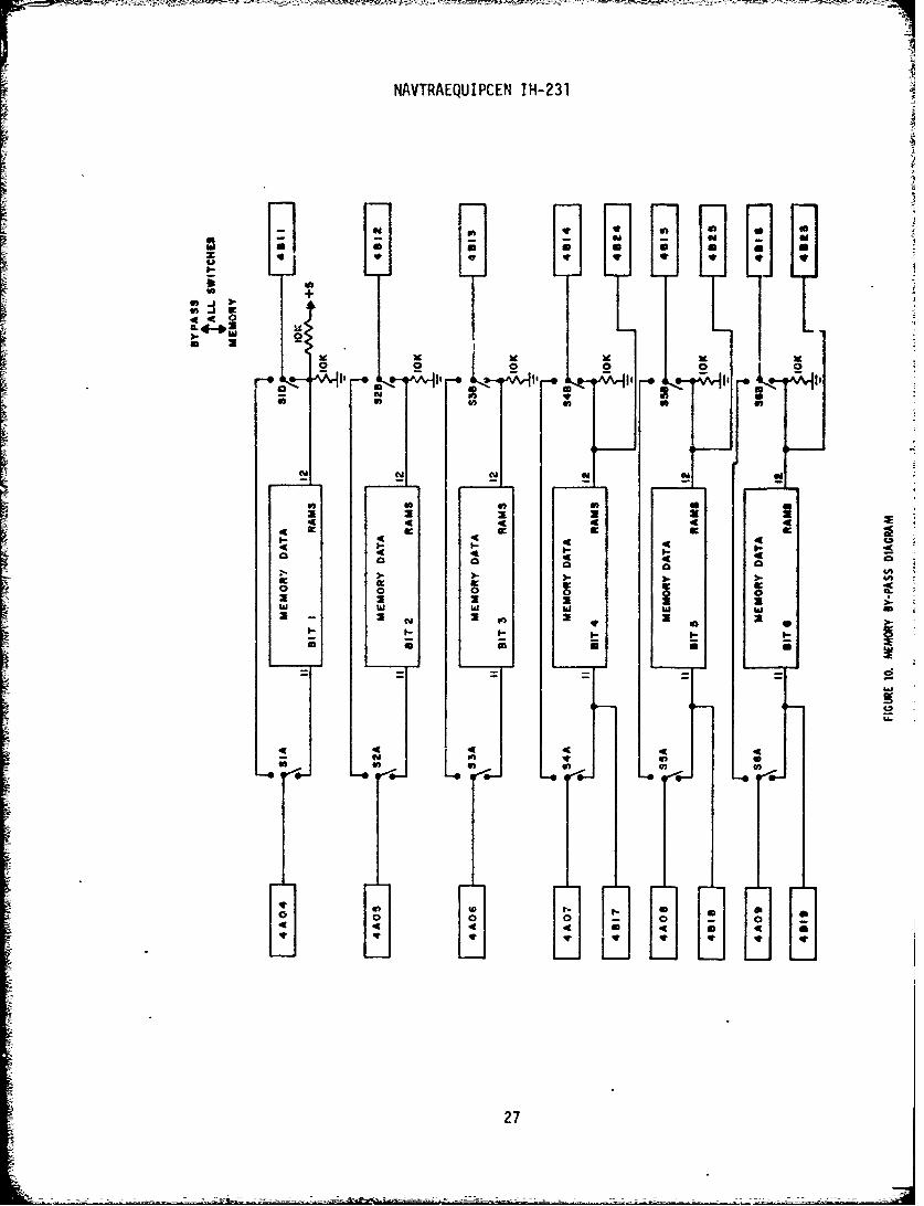
10. Memory By-Pass Diagram ...... .............................. 271. Timing Control......... ................................... 28
12. L cos Multiplier. ........................................ 29
13. Output Circuitry ... ......................................... 30
14. Headcrs/Card 6 ..................... ........................... 31
15. Band-Pass Filter ........................................ 32
16. Shift Registers/Cards 11-13 ................................ 33-41
17. RAM Address ................... ........................... 42
IF. 8!92X6 Memory................................................. 43
19. Doppler Control. ...... 44 5
20. Card Positions.................... ....................... 45
Sample Card fray-OUt .................... 46
22. Input/Output Block Diagram ................................. 47
447

NAVTRAEQUIPCEN IH-231
SECTION I
INTRODUCTION
This report doruments results of a study to determine the effective-ne';s of ki shipboarc target classification trainer, efforts included:
a. Analyzing immediate sonar tr•lning problems
b. Study of present target generation techniques
c. Investigated work being done by other facilities in government,universities, and industries.
d. Generation of preliminary system design.
e. Inve. igation of latest state-of-the-art design techniques for• 3 log, digital, and mem-ory systems.
f. Finalized design, construction, and testing of research tool.
S~SECTION I I
STATEMENT OF THE PROBLEM
A need exists for a means ',.iereby shipboard operator training in activesonar target detection and classificatiorn could be accomplished. Such echosimulators are desirable for use in mobile targets for submarines to trackin training exercises, in decoy devices for misleading enemy antisubmarinemeasures, and in stationary type sonar training devices. With this in mind,a sonar echo simulator was designed For the purpose of synthesizing echoesby utilizing a novel combir.ation of andlog and digital techniques to gene-rate the simulated echo.
5

NAVTRAEQUIPCEN It 131
SECTION 1l1
PROCEDURE
The concept of generating a simulated sonar echo is as follows: LThe simulator must contain a computer that solves for: Echo lengthand amplitude versus-
a. Target length
b. Angle of target relative to oncoming signal, i.e., aspectangle.
c. Frequency of echo versus velocity of target relative to shipi.e., Doppler.
The solution is dependent upon some initial normalized source level,transmitted pulse length, the appropriate parameters of sonar transmiss 4onand target reflection. Answers to the following questions must be providedbefore simulation can be accomplished:
a. What are the parameters that must be simulated in the targetecho return?
b. What are the electronic techniques that may enable the imple-menting of these techniques?
This report covers the answers to the above questions, and extensiveinvestigations have been performed on the transmissions of sound in theocean and on target echo returns.
From footnote 1, data was given that showed the effect of target
ech, es r-elativw to:
a. Highlight strenqth as a function of aspect anqle.
b. Target strength as a function of aspect angle.
c. Echo length as a function of aspect angle
From footnote 2, information was obtained that showed the effects ofecho return relative to:
1 R. Rubega, bescription of Target Strength Parameters Important toEcho Simulation (New York: Marine Resources, Inc. Oct 1968)Docuen •n-F878/6 /I
2 R. J. Urick, Principles of Underwater Sound for Engineers
6

u11
NAVTRAEQU•PCEN IH-231
a. Tarnet lenqth
b. Ascect lenqth
c. Relative velocity for Doppler shift
The two references set the parameters for the target echo. Nowwhat was needed was a method of implementing them electronically.
Two electronic methods were to be tried to simulate the targec echo.(Refer to footnote 3).
a. An electronically variable, tapped delayline.
b. Storaae. of- the sonar pulse in a memory, and reading the signalout at some delayed time to simulate target- range.
The two methods were partially combined into one approach for bddgetingpurposes.
The electrical sonar signal is first digitized and then stored in amemory. When the target return is due, the memory is read out and fed intothe electronically vari.ble delay line. This line consists of many seriesshift registers (SR) having multiple taps.
These taps represent the highli~gtsof the echo signal, and also givethe necessary controlling of the echo length. The gain of the total summedsignal is digitally controlled as a function of aspect angle to give thecorrect relative amplitude return. The frequency cf the echo signal variesas a function of relative velocity by controlling a beat-frequency mixingcircuit. A detailed description of the system follows with schematics ofeach phase shown as figures I to 21.
Murphree, Francis, Sonar Echo Simulator, U. S. Patent #3,610,798,
October 1971
7

NAVTRAEQUIPCEN IH-231
SECTION 1V
SONAk ECHO SIMUI.ATION SYSTEM
EXTERNAL INPUTS
a. Keying Gate of transmissions output signal
b. Trigger pulse to simulate target distance
c. Transmission output signal (low level)
PANEL CONTROL
a. Aspect Angle J
b. Target Length
c. Target Velocity
SECTION V
SYSTEM ANALYSIS
SIGNAL FLOW
A low-level samplc of the transmission output signal feeds intooperational amplifier (op amp) follower with an input impedance of lOOKonms (figure 4).
The amplifier output is fed into a mixer and voltage-controlledoscillator (VCO) that beats the input signal with the frequency of theoscillator. The resultant mixed frequencies are fed into a low passfilter of 40 db/octave (figure 5).
The low frequency signal is digitized at a 7500Hz rate, inverted,then fed as a 6 bit-word, having a resolution of 150 mv, to either asolid state memory, or directly to shift registers (figure 6).
The shift registers (S/R) consist of thirty 32 x 6 bit chips thatcontrol the length of the echo signal. Each S/R chip represents 10 feetof target length. A target of 10-300 feet can be simulated (figure 6).
The output cf each 6-bit S/R is fed intc. i digital to analog (D/A)device to change the signal back into the ?na'og form. Each D/A can besequentially turned on or off to shorten lie simulated echo.
8

NAVTRAEQUIJPCEN IH-231
All cutputs are then fed into summing op amps having a gain thatis a function of aspect angle (figure 13).
This signdl is then fed into a mixer and VCO. The oscillator frequencyis a function of velocity and simulates doppler effects,(
Af =2 v fc
where: v is the relative velocity
f is the transmitted frequency
c is the velocity of sound in water
Af is the change in frequency
In practical terms, and for a sound velocity of 4900 ft/sec.
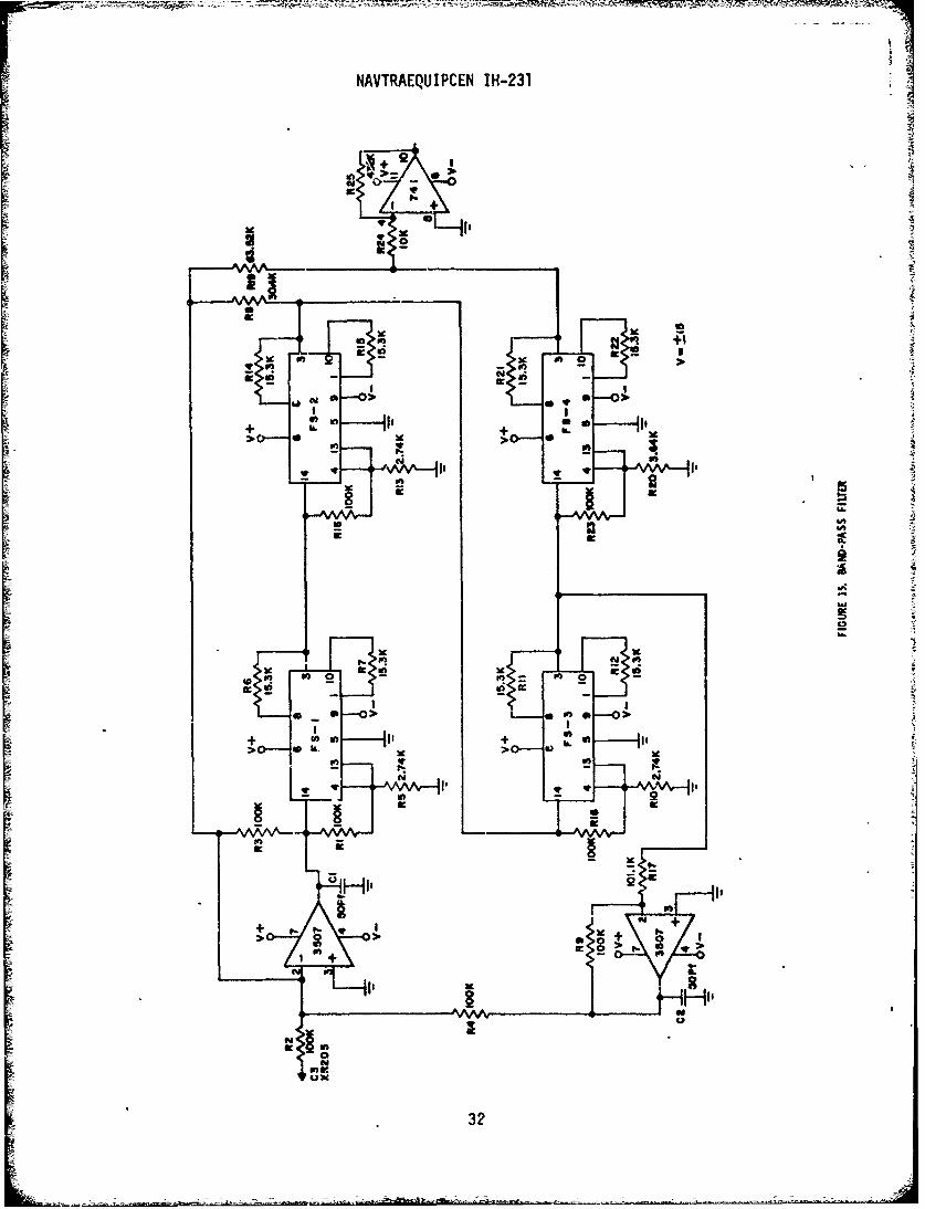
Af=±O.7 Hz/Knot KHzThe mixed signal is fed into a bandpass filter with a roll-off
of 40 db/octave and resulting signal fed to an output op amp. The outputof this amplifier is the simulated sonar echo and is a function of targetleogth doppler, and aspect angle, z
Echo Length = T + 2L cos e
C
where: T is the length of the transmitted signal
L is the target length
A 0 is the aspect angle
The input resistance to the op amp is a function of target distanceand varies the echo signal amplitude.
SECTION VI
PANEL CONTROLS
ASPECT ANGLE
This is a setting of a potentiometer, or may be a computer-controlledvoltage that is fed through a buffer op anpto a 5 bit output Analog toDigital (A/D converter.
9

NAVTRAEQUIPCEN IH-231
The output of the A/D is then fed to read-only memories (ROMs)Nos. 1, 2, and 4; each ROM having a 32 x 8 bit word (figure 7)
ROM No. 1 has 3 bits going to a UNIT readout (r/o lamp, 4 bitsto a TENS r/o lamp and 1 bit to a HUNDREDS r/o lamp. These readoutsvisually indicate aspect angle.
ROM No. 2 has 1 bit going to the HUNDREDS r/o, 2 bits to analogswitches that control aspect angle gain, and 5 bits to a D/A that feedsone input of the length control multiplier.
ROM No. 4 has its full 8 bits feeding a D/A that has a 4 millivoltresolution.
The output of the D/A feeds an op amp follower and then to one inputof the velocity control multiplier.
VELOCITY CONTROL
This is a setting of a potentiometer, or may be computer-controlledvoltage that is fed to one input of the velocity multiplier.
The output of the multiplier feeds a summing op amp. One input is•ei foi Lt ceti,-.E CLej' fitequency WuOaq: Whte~i Ltr veiocity input is zero.
The output of the op amp is the dc voltage for controlling the VCOthat simulates doppler.
LENGTH CONTROL
This is a setting of a potentiometer or may be a computer-controlledvoltage that feeds a dc voltage to a buffer op amp follower.
The output of the op amp goes to one input of the length multiplierand the multiplier output goes to another op amp follower (figure 12)
The output of the follower goes to a 5-bit D/A with a resolution of33 mV, and the output of the D/A goes to ROM No. 3 (figure 9).
10

INAVTRAEQUIPCEN IH-231
SECTION VII
RANDOM ACCESS SOLID STATE MEMORY
The Random Access Solid State Memory (RAY,) consists of forty-eight1024 x 1 bit chips that are wired to perform as an 8192 x 64bit word memorydevice (figure 18)
The timing and controls for the RAM are an important part of this designand an explanation follows (Figure 17)
At the time of the sonar transmission, a gate is monitored from theelectronics of the sonar. This gate is fed to an op amp having an inputimpedance greater than 10 meg-ohms. The output of the op amp feeds thetransmission gate to the UPIDOWN input at a counter-, an OR gate, two one-shot chips, and an inverter state.
At the start of transmission, a one-shot resets the 4 state counterbefore counting begins. The one-shot has a complimentary output that goesto a NOR gate that resets the 10-bit address counter and the 3 bit counterthrough an OR-Gate circuit. The 4 state counter starts counting a 7500 Hzclock at tke start of transmission, and stops the count at the end of trans-mission. This final count determines the length of the transmitter sonarsignal. At the same time the 10-bit counter addresses tht ine,•ory, ih, e"writA" mode, and stores the digitized sonar signal. At every count of 1024,this counter feeds a signal into a one-shot that resets the counter and•teps the 3-bit counter. The 3-bit counter supplies the logic to an 8 poleanalog switch that passes a chip-select signal through driver gates. Thisdetermines the portion of the memory to be selected. The counter is resetthrough a one-shot and the OR-gate.
When a target is presented as an input and the transmission gate isoff, a flip flop is activated that causes the 4-state counter to count-down from its present number. When the counter reaches zero, a decodertriggers a one-shot that then resets the flip-flop, gating the counter off.When the count-down begins, the 10-bit address counter and the 3-bitcounter activates the memory, which has now switched to a READ mode. READis stopped upon resetting the flip-flop. The final output signal is afunction of:
1. Target Length, L
2. Doppler Frequency, Af
3. Aspect Angle, e
•- 11
NAVTRAEQUIPCEN IH-231
SECTION VIII
RESULTS AND RECOMMENDATIONS
The finalized research tool was evaluated at the Key West Sonar TrainingSchool, and at the Naval Training Equipment Center, Orlando. The sonarvisual display was observed by several experienced sonarmen (operators/in-structors) and subjectively judged to be of a realistic quality echo. Tastswere pf~rformed varying the width of the sonar output signal and observingthe echo displays.
Installation of a prototype trainer in a Navy sonar training school isrecommended. Training effectiveness studies should be conducted in order todetermine the full extent of training transfer from the simulator to the realworld simulation. It is further recommended that this study be continued toincivude the effects on the echo signal due to multipath propagation and re-verberation. Methods should be investigated to feed the echo signal to thesonar set receiver processor input on a nonprogrammed basis. This wouldinclude additional electronics or a mini-computer to solve target motion andposition relative to own ship.
To summarize, this task has shown that there is a need for a shipboardecho sonar simulator. Using the newest electronic solid state technologies,the problems cf shipboard space and costs can be kept down to a minimalfigure which wou'ld allow sonar training at sea for all ships carryingoperational sonars.
12
S12

NAVTRAEQUIPCEN IH-231APPENDIX A
PARTS LIST OF MAJOR COMPONENTS
ITEM MANUFACTURER PART NO.
Operational Amplifier Fairchild U5B741
Waveform Generator Exar XR-205
Filter Kinetics FS-61
A/D Converter Datel ADC-EH
A/D Converter Datel ECONOVERTER
D/A Converter Datel DAC-298
D/A Converter Motorola MC 1406L
Hex Inverter Fairchild 9016
One-Shot Fairchild 9602
Nand-Gate Fairchild 9002
1X16 Decoder Fairchild 93LII
Binary Counter Fairchild 9316
Quad 2-Input AND Fairchild 9N08
And/Or Fairchild 9H52
Quad-Or Fairchild 9014
Dual Flip-Flop Fairchild 9024
UP/DOWN Decade Counter Signetics 8285A
Shift Register, Hex 32-Bit Signetics 2518
Read Only Memory, 32X8-Bit Signetics 8223
Random Access Memory, 1024Xl-Bit Intel 2102
Power Supply + 15 Volts Acopian TD15-250
Power Supply + 5 Acopian B5GT500
13

NAVTRAEQUIPCEN IH-231
"SG'lT-N ICl"1(S 8223, 82S23, 82S123 F I ELD -PROGRAMMABLE'25&BIT W3X81) READ.ONLY MEMORIES
Read-O~nlv Memory,;0 Io |-e e NPR-369 TRUTH TABLE (32 x 8) OCTAL DE,
B 87 B6 85 8 B3 B2 81 so ADO. IADDR
0 " *0 0o " 0 " 000 l a 0 o 0
o 6' o o o001 o 0o 0 oo- 1 0- 0' o: o 0 0 o 0 0• 2 2; -
0 0 0 0 0 0 1 3 " o3
19 0
So 1 0 0•'lb 0 1 " 0 0 1 0 4 4
S0 ,, 0 ,. 1 1 •- 1 0, 0 1 -. o 6
"0. o o 000 1 o o 0 ' o
-- ,0 1 o " 0 " -, 00Z 0 0' 0 1 2
-1' 0o 0 o 1 0o' 0 1 3
1 o 0 , 1 0 o 0 1 0 0 1 4
=''0 ., I o 0 1- o 1 6 121 0" 1 0 1 0 0 0 1 014
10 0 o 0 o o 0 2 0 16
0 0 0 0 0 0 0 0 071 17
0 0 0 0 1 0 L" 1 0 2 is
0 0. . 01 023
0 0 1 0 0 0 0 0 024 20
o 0 1 0 1 0 0' 1 0O2 5 '21
0 0 1 1 0 0 1 0 -02 6 22
0 0 1 1 11 0 1 1 02 7 23
o 1 0 0 0 1 0 0 "3 0 24
1 0 0 0 0 0 0 , 0 3 1 25
1 0 0 0 1 0 0 1 0 3 2 26
1 0 0 0 0 1 0033 27
10 0 0 1 1 0 1 ~3 4 23
"" 0 0 3 5 20
-"1 0 ' 0""0••, 0 30o I' .,0 ,: 0 $ 0. 0 o " 0,3-0 o N 30 7 31
-- -l 0 - -to -
14

NAVTRAEQUIPCEN IH-231
3'IGNETICS 8223, 82S23, 82S123 FIELD-PROGRAMMABLE."5S6-8IT (32X8) READ-ONLY MEMORIES
R-eiV•-dOiy- No.Mo 2 2
PR-369 TRUTH TABLE (32 x 8) OCTAL oEC.87 ~ B B ~ 83 ~iADOR. ADOR.8 8 B - 4 1 1 -3 82 - --- , 8
0 0 . 0 0 0
'.5~ 0~0 1 1 '
0,0 0 A 01 : . 1-=0 1 ~ 1 * 1i' 0 '~0 0 0 00 2~
0- 1 1 0 0 1 0 o0,0 3 3ilk -
1.. 0 1 0 1 - 0~ 0 ~ 0 4::'
0 0 . 0 0
1 .0 0 1 o o ' 0 0 6 6
0o- 0 0 0; 0 7 ,7
1 1 0 0 •0 0o 1 0
1 0 1 1 01. 1. 0 . 0 0 0 .
1 f 04 1 1 0 0''I 00 x 1 2' 12
00 0 0 o
";s 01 't "'T , 1 '7 • o 17 1
01 , 0 1 11. 10 ' 0 1 32 11
4' 1 10>~ >10 0 01 02 2 13
_.20 0 3 T1
1 0--0- 0 o 1 0 0"* 2
1 0o 1 oao o - 02 "2 "
0 Is1 1 0 0 0 1 0 2 ' 1 1
10 1 0 0 0 0 0 1 '27 2 3"-•-" •o 2 3 19 i o••-1 0 0 0 1 03%2
1 0- 1 0 0 0 1 ~ 0 1t 20
0 .1 1aa 11 0~ 211 0 0 0 032 2
E . 1 " 0 0. 1 ~0 24 22
0 1 0, 1 1 0 . 1 0 0 1 -03 00 1 0 1 0 0 0 0 1 ~' 0 3 1 20
0 1,-1 1 0-- -. 1- o t 3-. 2"
15

NAVTRAEQUIPCEN IH-231
Sr GNETfCS 8223, 82S23, 82S123 FIELD-PROGRAMMABLE256-BIT (32X8j READ-ONLY MEMORIES
MZyNo. 3
R-369 TRUTH TABLE (32X 8) OCTAL DEC.47 86 85 84 1 83 82 e1 B0 ADDR. ADOR,
0 0 .0 01 £ ~ s~ 1 0 ~0 1 ' 0 . 00 o~
1 _ .- 1 ,. 1. 1• -;". 0 1 o - Q7 - o , . _.1 . 110 0 1 =•. 1 .W 0 0 _3 13
1 1 1 •:''T0=' 1-T -T 0< 0 'p004 - •.4
11, 0.1 .0 1 0 4 4
0 T oi 5 1
'0 1 1'4 0 0 0 6 7
1 ~ - 1 1~ a '.i== 1 0 0 7 7
~o o 0 "o I o -_L~ z
0 1 91 -- 1 A 1 o 1 o~ 1 0' ; 1 0• •,o 1 2, i
A' i' 0 " 2
1 1 1 00 , 0141 1 1 �1>01'01 0" 1 ' 1 4 12
A .l
o ~ ~~ ~ 0 . 0 . 0 11 " 1 ' 1 j0 176 13
01 CH 0 1 1 1 41 i- 1 0 1
0 1 o,0 1 o02 3 17
S o 1 1 1 1 0' 1 A' 1 40 2 23o 1' 1 0 1 1 2~ 1 2Ž0 . 1O
o 1 0 1 1 1 6 ~ 4 2 22!
1 0 0, 0 111 1 -O2 7 23
1 0 G 1 1 1 ~ < i~3 0 24
1 o ' 1 0 1 1 1. et~ 1 0 31 25
1 0 1- ,1 1 1 ~ 3 2 26
1 1 0. 0 1 10 1 0 3 27
1 .o' 0 3 4 28
111 0 . 11 ' 1 1 0 35 29
0 i. ' 1 1 V 3 7' 30
16

NAVTRAEQUIPCEN IH-231
"sranETICS=2.3, 82S23, 82C123 FIELD-PROGRAMMAKLE266-BIT (32X8) READ-ONLY MEMORIES -. •
i~~~ ~ ~ ~ P~ Z-,r-IC M fV0
PR-369 TRUTH TA.BLE (32x ) OCTAL DEC.BI AD.I DR
87 a6 84 83 AD2R1 soO
o ' 1 12 1 . a I I
101 0 _ 0 • 2 1... , 0 0 0 704 1 0 3~o
" - 1 1 .�: ~ 0 4_ - o IC~0 1 0 0 "0 4 ~
4. 4- I• - •.:+ - ,
0 t' 0'0 4 0 0 - 0 0 ~ 00 a
0 o'+ o a o ,4+
z~t •'. o_o ' :z 4,_ t -• :... _
- -'ti :i: _ +'- o 7, 7.
o 0 o " o ' o 0 0 0 0
1 o -00 0 -- I 1o10 1 0 10 1 3 JA11
o ' i ]. 0 o 1 0 > 0 o 0• 2 10,0 1 * 0 .> '41 13 3
1 0 0 00 1 0 1 r: 0 1 1301 1
1 0 0
+_.-
1~~~ 2 0 :is a:* 0 v
1 1 0 0 0 1 0' ½~0 11 0 ' 0 1 1 '0 11 2 is
1 1 00 0 24 3 e1 1' "'0 2 5 21
0 " 00 0 0 0 0 0 0 5 220 0 0 0 0 0 0 o 0 027 23
0o 1 ~. 1 0 . 0 24
0~1 -0 00 00 0 03 1 25o < 0 o 0 0 1 0 0 2 2
0 1 1 o0~ 1 0 0 0 33 27
0' 1 1 0 10 0 03 21
0~~~ V 1 1: 1 1 c0 5 29
0 1 ' 1 1 " '11 00 3 0.~ ~ ~ ~ ~~~f 17 F-1~1 1 ~1>1 ~1
-o rq p -- - -

NAVTRAEQUIPCEN IH1-231
240
eso
lo-J
a.xS
Z 0
It IrIda
IL.
6:002
9118
- - -18

NAVTR'~fQIIIPCFII [H-23i
II,
att
ILI
19s
- ---- -- - -

NAYTRAEQUIPCEN IH-231
a C3 a
+ x
la'
-JC
tit
20

UL
IIAVTRAEQUIPCEN IH1-231
00
~ OJ
t, - z
le 2 X5 41
CVI
-HI,so 0,
41c
> ON t- 319
z 1~
21 :

NAVTRAEQUIPCEN IH-231 '
- -4
I,,
-- 1 0l ,
000A
.9 a
so IV-T
2Cd
aI
ibfn~
to,
00
Cie0 1O w 91
221

NIAVTRAEQU IPCEN IH-231
++ +
_. w be. o_ ._
0 00 0 0 a
+ T
I S
2 0 " -0-._R
+
0.
x -f _zH ,, a
Li Iii
2>4a"
10 Z S0
_ * 4 4 0
LI L
ci f
CLI4
00ut +I +0-in
00
00 + +
23

NAVTR.AEQIUTPCEN IH-231
2
n: I
1010 10 19O1 10. ,0 1;
001
W0* 0 0:4
e~o B+I SB org S 6
0 0
22
g Z +1 t % 0
0 +1N
V a V9
+ +'
424

iiNAVTRAEQVIPCEN IH-231
t7�
I. Z.j Pr
ii
wo+ OW
2
U
IA -
Sah5C,
0� U-a, 4 v�v*:w�r u+ a
2
p. U0hi0
a,aW 0
+a,- - I. 'a- - tHI.
25

NAVTREQUIPCEN IH-231
000 - 9 t
E+ -1 EL EE W
0s
1' _
u,-1~I5 ---doeLm0 0
u4 0-7o
233
10 4I~i 2;
NAVTRAEQUIPCEN IH-231
log 0 0 0
-0 -AA l
Ind
4.4
4 4 4 4AE
a ad 44
0 0
27

?4AVRAEQUIPCEN11,1-231
+" a
4Lu
0 ConIng___a-
28

NAVTRAEQUIPCEN IH-231
sbo
II1 0
+
Ta
2q

NAVTRAEQVIPCEN IH-231
I,
Kd
AA6
on-,
0
0 La 2
guiif
30 ~

NAVTRAEQUIPCEN IH-231
9
44 4 UU /4 tmlb. er r , . :
* *x
GO,
____IIT_111 TT
4L___ ____ __It
me 14 U
OwIhi
oac 44
31
NAVTRAEQUIPCEN IH-231
'A 2+
I +
- I a
+ , ', __n , -4 -- ,,
0 0
-2 -,
c L
> 0 >g~go
4' 32

LI
NAVTRAEQUIPCEN IH-231
g
TO CONTINUATION OF S14IFT REGISTER CIRCUIT(TOX3 SECTION)
•.C) .• _II _. ,ft
4cc
33 L t- ,-
~0 C-5 I i
33'

NAVTRAEQUIPCEN IH-231
TO CONTINUATION OF 3HIFT REGISTERt CAM 0(T0?7 tECTION)
a .1
044
]I T iN. 1
-0+
iti
+ U
1~I 39~-~4 14 In-
Lft
k- on
-I
ýi"
*100$

NAVTRAEQUIPCEN IH1-231
L* 1
I- IL
e4 to I
TTV111-__NY 40D
p. *ib-oB - Ni-Jill'
35K

NAVTRAEQUIPf.FN IH-231 I
dc Icc a b .
T.
ILI
TO CONTINUATION OF SHIFT REGISTER CIRCUIT
(TOV3 SECTION)
~~0I "
I •- a -• -.
I - _-_-.. ._---___-_ ",-
= 2 * * I,
2 - V:
".- c_ E3 + + -
uN
In ell
T, T
L4T2+~
+=In T
T Ln
36

Z7
NAVTRAEQUIPCEN IH-231
TO CONTINUATION OF SHIFT REGISTER CARD *
MI AlF IiL L
44
of -- 2
-2r
711L]Z +7
k'

NAVTRAE-QtIPCEN IH-231
40
F _ _ __ _ _ _
ID~IL
4m
-,Ot
c~atu
I
IN4A3M

NAVTIRAEQUIPCEN IH1-231
0
IL a
In 0
-I R
NO
I I9


NAVTRAEcQUJIPCEN IH1-231
6:u -
0 0*
~;4u
9 -H 0i~j:___
-jt
411

NAVTrRAEQUIPCEN 11H-231
T~ T TT
I a
42 44 J

?4AVTRAEQUIPCEN IH-231
le
so 0 212 f *0
01S .9 I I I I IIII l IJ
4= Et 4~ T
aI- I-
t t
-j Ti ii
4-3

NAYTRAEQUIPCEN IH-2a1
I Iio] i
-+
2 _0 *ell*1AMC
1* + + ++ + + + -"
> *O- - C jST
E E SLa
00
SCE
EJED
44

NAVTRAEQUIPCEN IH-231
N; /,1,,
•0 owU:-° U"I - 1aa -.8c2
000
II
ito___ -0C
-0" -i' I =_I.
~ I
-- .-.. ,
"I 4N4

NAVTRAEQU IPCEN IH-231
DDDDDDDDJ --L- LIE]-S
!3DDDDD9.---LIDDDD -m---m-A
A 31 25 20 15 10 5 A COMIMCNENT S1Da 4.--- OP WIRE WRAP SIDE
46

-- -4 - ý T-' - -- " - -- -
NAVTRAEQtJIPEN IH-231
rYL~LL C)-f~
0 Z: :D I L000N
0<L CL-l4L0•A LL LLQJ
<II . _I .....;3 11:~vI LV )-J
o <
I-~~> Li -

SURFACE WARFARE TRAINING DISTRIBUTION LIST
NOTE
Mailing labels are prepared, when needed, as a computerlisting, the source of which is updated on a weekly basis.It is not practical to prepare distribution lists each timelabels are prepared. Therefore such lists are preparedsem•annually, and a slight discrepancy may exist betweenthe addressees on this list and those appearing on thelabels used to distribute this publication.
Chief Naval Education and Training, Code 017, NAS, Pensacola, FL 32508
Officer in Charge, MDWP Contract Supervisor, Staff SACLANT, ASWResearch Center, APO New York 09019
Scientific Technical Information Office, NASA, Washington, DC 20546
NASA Langley Research Center Library, Langley AFB, VA 23365
Chief of Nava.l 'ducation and Training Support, Pensacola, FL 32509

SUBSURFACE WARFARE DISTRIBUTION LIST
NOTE
Mailing labels are prepared, when needed, as a computerlisting, the source of which is updated on a weekly basis.It is not practical to prepare distribution lists each timelabels are prepared. Therefore such lists are prepared
semianrually, and a slight discrepancy may eidst betwveen
the addressees on this list and those appearing on thelabels used to distribute this publication.
Scientific Technical Information Office, NASA, Washington, DC 20546
Commander, Naval Surface Weapons Center, ATTN: Library, RM 1-327,Silver Spring, MD 20910
Chief Naval Education and Training, Code G17, NAS, Pensacola, FL 32508
Chief of Naval Education and Training Support, Pensacola, FL 32509
.iI