ad 2000-mb - b6 -10-2006
DESCRIPTION
AD 2000-MB - B6 -10-2006TRANSCRIPT
AD 2000-Merkblatt ICS 23.020.30 October 2006 edition
Design of
pressure vessels
Cylindrical shells subjected to external overpressure
AD 2000-Merkblatt
B 6
The AD 2000-Merkblätter are prepared by the seven associations listed below who together form the “Arbeitsgemeinschaft Druck-behälter” (AD). The structure and the application of the AD 2000 Code and the procedural guidelines are covered by AD 2000-Merk- blatt G 1.
The AD 2000-Merkblätter contain safety requirements to be met under normal operating conditions. If above-normal loadings are to be expected during the operation of the pressure vessel, this shall be taken into account by meeting special requirements.
If there are any divergences from the requirements of this AD 2000-Merkblatt, it shall be possible to prove that the standard of safety of this Code has been maintained by other means, e.g. by materials testing, tests, stress analysis, operating experience.
Fachverband Dampfkessel-, Behälter- und Rohrleitungsbau e.V. (FDBR), Düsseldorf Hauptverband der gewerblichen Berufsgenossenschaften e.V., Sankt Augustin Verband der Chemischen Industrie e.V. (VCI), Frankfurt/Main Verband Deutscher Maschinen- und Anlagenbau e.V. (VDMA), Fachgemeinschaft Verfahrenstechnische Maschinen und Apparate, Frankfurt/Main Stahlinstitut VDEh, Düsseldorf VGB PowerTech e.V., Essen Verband der TÜV e.V. (VdTÜV), Berlin
The above associations continuously update the AD 2000-Merkblätter in line with technical progress. Please address any proposals for this to the publisher:
Verband der TÜV e.V., Friedrichstraße 136, 10117 Berlin
Contents
0 Foreword
1 Scope
2 General
3 Symbols and units
4 Safety factor
5 Exploitation of the permissible design stress in welded joints
6 Weakenings
7 Calculation
8 Minimum wall thickness
9 Literature
Appendix 1: Explanations
0 Foreword
The AD 2000 body of regulations can be applied to satisfy the basic safety requirements of the Pressure Equipment Directive, principally for the conformity assessment in accordance with modules “G” and “B + F”.
The AD 2000 body of regulations is structured along the lines of a self-contained concept. If other technical rules are used in accordance with the state of the art to solve related problems, it is assumed that the overall concept has been taken into account.
The AD 2000 body of regulations can be used as appro-priate for other modules of the Pressure Equipment Direc-tive or for different sectors of the law. Responsibility for testing is as specified in the provisions of the relevant sector of the law.
1 Scope
The design rules below apply to smooth cylindrical shells serving as shells of pressure vessels and to tubes sub-jected to external pressure having a Da/Di-ratio ≤ 1,2. In
the case of tubes with Da ≤ 200 mm they apply further-more up to a ratio Da/Di = 1,7. The cylindrical shells may be reinforced or unreinforced.
The pressure must act over the entire periphery. Addi-tional account shall be taken, e.g. in accordance with [10], of axial loads which are higher than those attributable to the external overpressure.
2 General
2.1 This AD 2000-Merkblatt shall only be used in con-junction with AD 2000-Merkblatt B 0.
In the case of heat-exchanger tubes, except where special agreements are reached between manufacturer and cus-tomer/user, the margin to be allowed for thinning is c2 = 0.
2.2 In the case of pressure vessels made of grey iron, the performance of design calculations for internal pressure using the safety factors given in Table 1 is sufficient, for which purpose the external overpressure is substituted for the internal pressure.
Supersedes Februar 2005 edition; | = Amendments to previous edition
AD 2000-Merkblätter are protected by Copyright. The rights of use, particularly of any translation, reproduction, extract of figures, transmission by photomechanical means and storage in data retrieval Systems, even of extracts, are reserved to the author. Carl Heymanns Verlag has taken all reason-able measures to ensure the accuracy of this translation but regrets that no responsibility can be accepted for any error, omission or inaccuracy. In cases of doubt or dispute, the latest edition of the German text only is valid.
AD 2000 B6 30.11.2006 17:49 Uhr Seite 2
ww
w. b
eut h
. de
© B
eut h
Ve r
lag
Gm
b H, D
-10 7
72 B
erlin
BA75E3EC9238321DFDAD9E8AEA77DB4BB3DF8BFFFF8CE3D73A9D38EFA8
AD
200
0 C
od
e -
Issu
e 20
11-0
1
AD 2000-Merkblatt Page 2 AD-2000-Merkblatt B 6, 10. 2006 edition
3 Symbols and units
In addition to AD 2000-Merkblatt B 0 the following applies:
bm double taper length in mm l length of cylinder between effective
reinforcements (buckling length) in mm lm supporting shell length in mm pe elastic buckling pressure of stiffening in bar q in this context: flattening in mm u out-of-roundness in %
4 Safety factor
4.1 The safety factors for plastic deformation in the op-erational and test conditions are given in Table 1.
4.2 The safety factor for elastic buckling, irrespective of the material, is SK = 3,0 and is valid for u ≤ 1,5 %, with u being determined in accordance with 7.3.4.
In the case of u > 1,5 %, SK = 2,25 + 0,5 u. Where a test-ing pressure greater than 1,3 p is stipulated, SK shall be at least 2,2 SK/3.
Table 1. Safety factors
Material Safety factor for elastic limit, yield point or creep strength
Safety factor S for the material
at design temperature
Safety factor S’ at test pressure
1. Rolled and forged steels 1,6 1,1
2. Cast steel 2,0 1,5
3. Spheroidal graphite cast iron to DIN EN 1563
3.1 EN-GJS-700-2/2U EN-GJS-600-3/3U 5,0 2,5
3.2 EN-GJS-500-7/7U 4,0 2,0
3.3 EN-GJS-400-15/15U 3,5 1,7
3.4 EN-GJS-400-18/18U-LT EN-GJS-350-22/22U-LT 2,4
1,2
4. Aluminium and its alloys – Wrought materials 1,6 1,1
Safety factor for tensile strength
5. Grey cast iron to DIN EN 1561 6,0 3,5
6. Copper and its alloys including rolled and cast bronze 4,0 2,5
5 Exploitation of the permissible design stress in welded joints
Irrespective of the scope of testing as defined in AD 2000-Merkblatt HP 0, General table 1, when performing design
calculations for external pressure the exploitation of the permissible design stress in welded joints need not be considered.
6 Weakenings
Calculations for openings shall be performed in accor-dance with AD 2000-Merkblatt B 9, with p as the internal pressure. Openings in double shells which are braced relative to one another by nozzles need not be considered when calculating the wall thickness.
7 Calculation
7.1 General
7.1.1 Calculations shall be performed for elastic buckling in accordance with 7.2, and for plastic deformation in accordance with 7.3. The lowest calculated value for p1 and p2 is the essential factor in establishing the permissi-ble service overpressure.
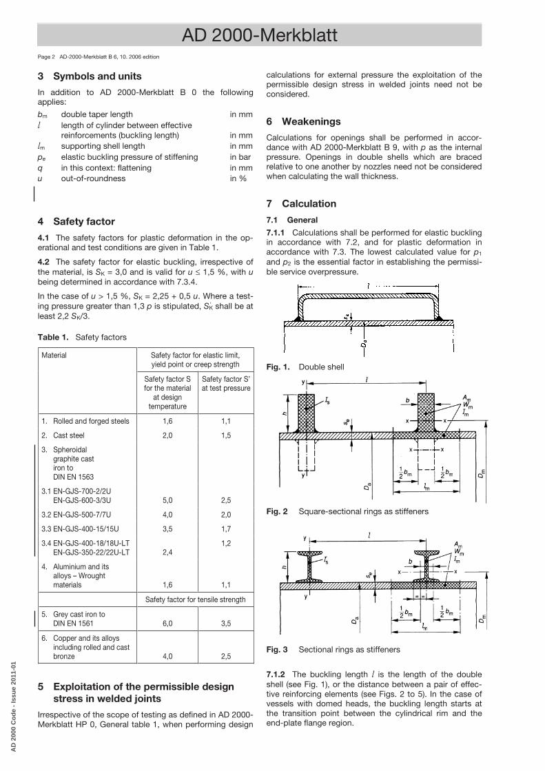
Fig. 1. Double shell
Fig. 2 Square-sectional rings as stiffeners
Fig. 3 Sectional rings as stiffeners
7.1.2 The buckling length l is the length of the double shell (see Fig. 1), or the distance between a pair of effec-tive reinforcing elements (see Figs. 2 to 5). In the case of vessels with domed heads, the buckling length starts at the transition point between the cylindrical rim and the end-plate flange region.
‘
AD 2000 B6 30.11.2006 17:49 Uhr Seite 3
BA75E3EC9238321DFDAD9E8AEA77DB4BB3DF8BFFFF8CE3D73A9D38EFA8
AD
200
0 C
od
e -
Issu
e 20
11-0
1

AD 2000-Merkblatt AD-2000-Merkblatt B 6, 10. 2006 edition Page 3
AD 2000 B6 30.11.2006 17:49 Uhr Seite 4
p1 =ESK
20
n2− 1 1+ nZ
22⋅se− c1− c2
Da+ 80
12 1− ν2⋅n2− 1+
2 n2− 1− ν
1+ nZ
2 ⋅
se− c1− c2Da
3
(1)
n = 1,63 ⋅D3a
l2 se− c1− c24 (2)
p1 =ESK⋅ 201− ν2 ⋅
se− c1− c2Da
3
(3)
p2 =20 ⋅ KS⋅se− c1− c2
Da⋅
1+1,5u ⋅ 1− 0,2
Da
l ⋅ Da
100 se− c1− c2
1
p2 =20 KS⋅se− c1− c2
Da(5)
p2 =30 KS
se− c1− c2l
2
(6)
u = 2 ⋅Di max− Di min
Di max + Di min⋅ 100 (7)
u = 4Da⋅ q ⋅ 100 (8)
BA75E3EC9238321DFDAD9E8AEA77DB4BB3DF8BFFFF8CE3D73A9D38EFA8
AD
200
0 C
od
e -
Issu
e 20
11-0
1

AD 2000-Merkblatt Page 4 AD-2000-Merkblatt B 6, 10. 2006 edition
This also applies to the designs in Figs. 2 and 3 if the conditions in equations (9) and (10) are satisfied in con-junction which equations (11) and (12).
In order to determine geometrical quantities Am, Wm and Im (see Figs. 2 and 3), the supporting shell width lm shall first be determined using equation (12). The geometrical moment of inertia Im and the section modulus Wm are to be referred to the centre-of-gravity axis of the cross sec-tion that is parallel to the shall axis (see x–x axis in Figs. 2 and 3) which consists of the cross section of the stiffener and the supporting part of the shell of length lm. Dm is the relevant centre-of-gravity diameter.
eK <· pSp (9)
SK
ppSu
WDp
ADp
/·–1·
·8000··
+·20
·
eKm
2a
m
am Il (10)
where l
I··)++–(·)–1(
··240=
2m21ea
2m
eDccsD
Ep
ν (11)
and bccsDbb +)––(··1,1=+= 21eamml (12)
whereby a length exceeding length l shall not be used for the length lm which is also carrying the load. The strength characteristic value of the stiffening ring is to be used for K. For safety factor S, see AD 2000-Merkblatt B 0.
Narrow, high stiffeners as shown in Fig. 2 may buckle; the height of the stiffener shall therefore not exceed 8 times the width. For profiles as shown in Fig. 3, the required geometrical moment of inertia relative to the centre-of-gravity axis y–y depends on the profile heigth h and is
3000
4
sh
I
7.4.2 In the design of the whole shell an allowance can be made for the effect of heating ducts (see Figs. 4 and 5). In equation (1) the permissible pressure will then be in-creasing in the ratio of moments of inertia with and with-out heating ducts (referred to the relevant centre-of-gravity axis x – x or x′ – x′) and in equation (4) in the ratio of the cross sectional areas of vessels with and without heating ducts.
7.4.3 Where reinforcing elements are jointed to the shell by means of discontinuous welds, the fillet welds at each side shall encompass at least one third of the shell cir-cumference. The pitch adopted for the fillet welds in the peripheral direction must be at least 300 mm, and the number of weld discontinuities shall be at least 2 n. The number n of buckling ridges is obtained as indicated in 7.2.1.
8 Minimum wall thickness
8.1 For the minimum wall thickness of seamless, welded or brazed cylindrical shells, the stipulated value is 3 mm.
8.2 Contrary to the stipulation made in 8.1, for the minimum wall thickness in the case of cylindrical shells made of aluminium and its alloys, the relevant value is 5 mm.
8.3 For exceptional cases, reference shall be made to AD 2000-Merkblatt B 0, Section 10.
8.4 In the case of heat-exchanger tubes, the minimum wall thickness may be less than the values stipulated in 8.1 and 8.2.
9 Literature
[1] Hütte, I.: 28th edition, p. 953. Verlag Ernst und Sohn, Berlin.
[2] Meinke, H.: Berechnung und Konstruktion zylin-drischer Behälter unter Außendruck. Konstruktion 11(1959) No. 4, p. 131/38.
[3] v. Mises, R.: Der kritische Außendruck zylindrischer Rohre. VDI-Z 58 (1914) No. 19, p. 750/55.
[4] Schwaigerer, S., u. A. Konejung: Die Festigkeits-berechnung von Flammrohren. Konstruktion 2 (1950) No. 1, p. 17/23.
[5] v. Reht, Th.: Unmittelbare Berechnung der Beulwel-len in Gleichung (1) des AD-Merkblattes B 6. TÜ 12(1971) No. 12, p. 362.
[6] BS 5500 – Specification for unfired fusion welded pressure vessels, 1982; published by British Stan-dards Institution.
[7] Link, H.: Berechnung ringversteifter Bohrschachtver-rohrungen aus Stahl in den USA (Design of Ring-stiffened Pit Pipework Made of Steel in the USA). Structural Steel Engineering 9 (1981), p. 284/287.
[8] Ebner, H.: Festigkeitsprobleme von U-Booten. Schiffstechnik, Forschungshefte für Schiffbau und Schiffsmaschinenbau 14 (1967) Vol. 74, p. 95/113.
[9] Meinke, H.: Rohre in Apparaten unter Außendruck. Chem.-Ing.-Technik 3 (1978), p. 215/17.
[10] Deutscher Ausschuß für Stahlbau: Beulsicherheits-nachweise für Schalen, DASt-Richtlinie 013, Juli 1980.
[11] Feder, G.: Zur Stabilität ringversteifter Rohre unter Außendruckbelastung (Stability of Ring-stiffened Tubes Subjected to External Pressure Loading). Schweizerische Bauzeitung, 89, Annual Set, Vol. 42 (21. 10. 1971), p. 1043/1051.
≤
≤
AD 2000 B6 30.11.2006 17:49 Uhr Seite 5
BA75E3EC9238321DFDAD9E8AEA77DB4BB3DF8BFFFF8CE3D73A9D38EFA8
AD
200
0 C
od
e -
Issu
e 20
11-0
1
AD
2000-Merkb
latt A
D-2000-M
erkblatt B
6, 10. 2006 edition P
age 5
AD 2000 B6 30.11.2006 17:49 Uhr Seite 6
BA75E3EC9238321DFDAD9E8AEA77DB4BB3DF8BFFFF8CE3D73A9D38EFA8
AD
200
0 C
od
e -
Issu
e 20
11-0
1

AD 2000 B6 30.11.2006 17:49 Uhr Seite 7
BA75E3EC9238321DFDAD9E8AEA77DB4BB3DF8BFFFF8CE3D73A9D38EFA8
AD
200
0 C
od
e -
Issu
e 20
11-0
1

AD
2000-Merkb
latt A
D-2000-M
erkblatt B
6, 10. 2006 edition P
age 7
AD 2000 B6 30.11.2006 17:49 Uhr Seite 8
BA75E3EC9238321DFDAD9E8AEA77DB4BB3DF8BFFFF8CE3D73A9D38EFA8
AD
200
0 C
od
e -
Issu
e 20
11-0
1

AD 2000-Merkblatt Page 8 AD-2000-Merkblatt B 6, 10. 2006 edition
Annex 1 to AD 2000-Merkblatt B 6
Explanations to AD 2000-Merkblatt B 6 To 4.2 and 7.3.4
Available experience indicates that SK = 3,0 is adequate in the case of out-of-roundness up to u = 1,5%. The influ-ence associated with the out-of-roundness was deter-mined in accordance with the literature [4], the basis adopted being SK = 3,0 for u = 1,5%.
According to AD 2000-Merkblatt HP 1 Table 1, out-of-roundness shall not usually exceed 1,5% in the presence of external pressure stresses and where s/D ratios do not exceed 0,1.
In the case of tubes to AD 2000-Merkblatt W 4 and tubes made of austenitic steels to DIN EN ISO 1127 (for DN < 150 in tolerance classes D 2, T 3 and for DN ≥ 150 in tolerance classes D 1, T1), the safety factor for elastic buckling in normal cases can also be determined directly, as an approximation, as a function of the nominal diame-ter of the tube (DN in mm):
10 ≤ DN ≤ 50 : SK = 8,25 –DN10
50 < DN : SK = 3,25
To 7.2.3
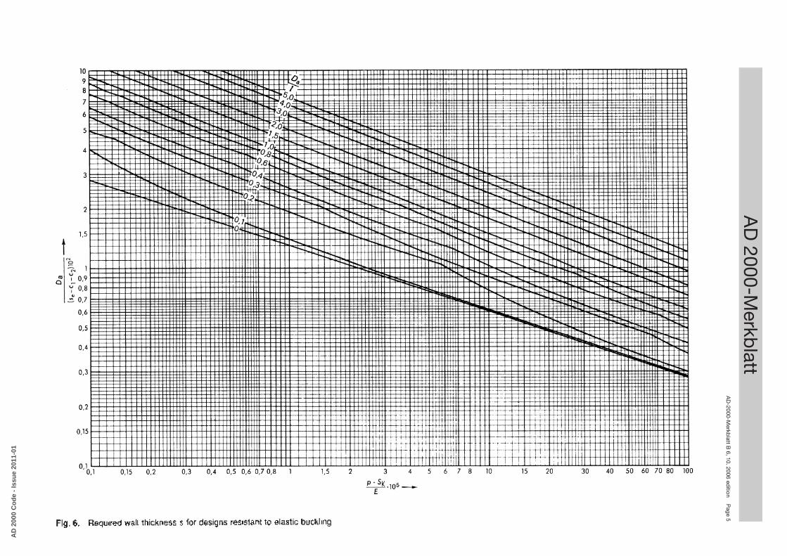
Equation (3) is an exact expression for the cylindrical shell of infinite length (Da/l = 0), and can be derived from equa-tion (1). Using equation (3), the pressures obtained are lower than when equation (1) is employed. The differences are plotted for various Da/l-ratios in Fig. A1. For the ratios s/Da > 0,0025 and Da/l < 0,04, the differences are less than 5%.
To 7.3.2
Fig. 8 is an exact representation for the cylindrical shell of infinite length (Da/l = 0). For cylindrical shells of infinite length, the pressure obtained are lower than when equation (4) is employed. The differences are plotted for various Da/l-ratios in Fig. A2. For ratios of Da/l ≤ 0,2, the differences are less than 5%.
Fig. A1. Design calculations for elastic buckling – differences between the pressures determined using equations (1) and (3), plotted as a function of (se – c1 – c2)/Da and Da/l.
Fig. A2. Design calculations for failure due to plastic deformation – differences between the pressures obtained using equation (4) and those obtained according to Fig. 8, plotted as a function of (se – c1 – c2)/Da, Da/l, and the out-of-roundness u.
p E
qua
tion
(1)
p E
qua
tion
(3)
p E
qua
tion
(4)
p F
ig. 8
AD 2000 B6 30.11.2006 17:49 Uhr Seite 9
BA75E3EC9238321DFDAD9E8AEA77DB4BB3DF8BFFFF8CE3D73A9D38EFA8
AD
200
0 C
od
e -
Issu
e 20
11-0
1

AD 2000-Merkblatt AD-2000-Merkblatt B 6, 10. 2006 edition Page 9
AD 2000 B6 30.11.2006 17:49 Uhr Seite 10
σ=p ⋅ lm ⋅ Da
20 ⋅ Am+
p ⋅ l ⋅ D2a
8000 ⋅Wm⋅ u1− p pe
(A1)p= pe⋅
1+ SK ⋅ G+ H2 ⋅ SK
−1+ SK ⋅G+ H
2 ⋅ SK
2
− GSK
(A2)
G = KS⋅ 20 ⋅ Am
pe ⋅ lm ⋅ Da(A3)
H = u ⋅ Da ⋅ l ⋅ Am
400 ⋅ lm ⋅Wm(A4)
BA75E3EC9238321DFDAD9E8AEA77DB4BB3DF8BFFFF8CE3D73A9D38EFA8
AD
200
0 C
od
e -
Issu
e 20
11-0
1

BA75E3EC9238321DFDAD9E8AEA77DB4BB3DF8BFFFF8CE3D73A9D38EFA8
AD
200
0 C
od
e -
Issu
e 20
11-0
1

BA75E3EC9238321DFDAD9E8AEA77DB4BB3DF8BFFFF8CE3D73A9D38EFA8
AD
200
0 C
od
e -
Issu
e 20
11-0
1
AD 2000 B6 30.11.2006 17:49 Uhr Seite 1
Beuth Verlag GmbH
Publisher: Source of supply:
D-10772 BerlinTel. +49 30 / 26 01-22 60Fax +49 30 / 26 01-12 60
Verband der TÜV e.V.
E-Mail: [email protected] http://www.vdtuev.de
BA75E3EC9238321DFDAD9E8AEA77DB4BB3DF8BFFFF8CE3D73A9D38EFA8
AD
200
0 C
od
e -
Issu
e 20
11-0
1