actuatorline – robot series · @all the drawings in this catalogue are available in cad files on...
TRANSCRIPT

www.rollon.com
ACTUATORLINE – ROBOT series
@ Nota: tutti i disegni riprodotti nel presente stampato sono disponibili sul sito www.rollon.com in formato CAD
Il sistema - The system 3
I componenti - The components 4
Il sistema di traslazione - The linear motion systemGuide a ricircolo di sfere - Ball bearing guides 5Guide a rotelle ad arco gotico - Lancet arch bearing guides 5
Vista generale con caratteristiche tecniche principali General view with main technical characteristics 6
8PS 001 TOBOR
9C2-PS 001 TOBOR
01EC 001 TOBOR
11C2-EC 001 TOBOR
21PS 031 TOBOR
31C2-PS 031 TOBOR
41EC 031 TOBOR
51C2-EC 031 TOBOR
61PS 061 TOBOR
71 C2-PS 061 TOBOR
81EC 061 TOBOR
91C2-EC 061 TOBOR
02PS 022 TOBOR
12C2-PS 022 TOBOR
Tipologie di trasmissione - Transmission features:Riduttori epicicloidali - Planetary gears 22Riduttori a vite senza fine - Worm gears 23Alberi sporgenti - Simple shafts 24Alberi sporgenti per montaggio encoder - Simple shafts for encoder assembly 24Alberi cavi - Hollow shafts 25
Montaggio e accessori - Assembly and accessories 26
Lubrificazione - Lubrication 28
Protezioni - Protections 29
Sistemi multiasse - Multiaxis systems 30
Dati tecnici supplementari - Additional technical data 32
Codici di identificazione - Identification codes 33
Scheda dati - Data sheet 34
Indice - Contents
@ All the drawings in this catalogue are available in CAD files on www.rollon.com
33Il sistema - The system
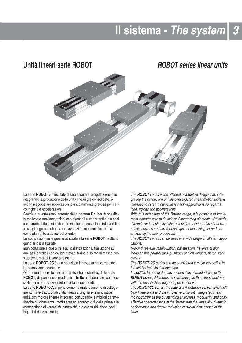
La serie ROBOT è il risultato di una accurata progettazione che,integrando la produzione delle unità lineari già consolidate, èrivolta a soddisfare applicazioni particolarmente gravose per cari-co, rigidità e accelerazioni.Grazie a questo ampliamento della gamma Rollon, è possibi- le realizzare movimentazioni con elementi autoportanti a più assicon caratteristiche statiche, dinamiche e meccaniche tali da ridur-re sia gli ingombri che alcune lavorazioni meccaniche, primacompletamente a carico del cliente.Le applicazioni nelle quali è utilizzabile la serie ROBOT risultanoquindi le più disparate:manipolazione a due o tre assi, palletizzazione, traslazione sudue assi paralleli con carichi elevati, traino o spinta di masse con-siderevoli, cicli di lavoro stressanti.La serie ROBOT- 2C è una soluzione innovativa nel campo del-l’automazione industriale.Oltre a mantenere tutte le caratteristiche costruttive della serieROBOT, dispone, sulla medesima struttura, di due carri con pos-sibilità di motorizzazioni totalmente indipendenti.La serie ROBOT-2C, si pone come naturale elemento di collega-mento tra le tradizionali unità lineari a cinghia e le innovativeunità con motore lineare integrato, coniugando le migliori caratte-ristiche di robustezza, modularità ed economicità delle prime allecartteristiche di versatilità, dinamicità e drastica riduzione degliingombri delle seconde.
The ROBOT series is the offshoot of attentive design that, inte-grating the production of fully-consolidated linear motion units, isintended to cater to particularly harsh applications as regardsload, rigidity and accelerations.With this extension of the Rollon range, it is possible to imple- ment systems with multi-axis self-supporting elements with static,dynamic and mechanical characteristics able to reduce both ove-rall dimensions and the various types of machining carried outentirely by the user previously.The ROBOT series can be used in a wide range of different appli-cations:two-or three-axis manipulation, palletisation, traverse of highloads on two parallel axis, push/pull of high weights, harsh workcycles.The ROBOT- 2C series can be considered a major innovation inthe field of industrial automation.In addition to preserving the construction characteristics of theROBOT series, it features two carriages, on the same structure,with the possibility of fully independent drive.The ROBOT-2C series, the natural link between conventional belttype linear units and the innovative units with integrated linearmotor, combines the outstanding sturdiness, modularity and cost-effective characteristics of the former with the versatility, dynamicperformance and drastic reduction of overall dimensions of thelatter.
Unità lineari serie ROBOT ROBOT series linear units

@ Nota: tutti i disegni riprodotti nel presente stampato sono disponibili sul sito www.rollon.com in formato CAD
Profilo in alluminio
I profili autoportanti usati per le unità lineari Rollon serie ROBOT, sono stati studiati e realizzati in collaborazione conun’azienda leader del settore al fine di ottenere estrusi cheriescano a coniugare doti di elevata resistenza meccanica a unpeso contenuto.Il materiale impiegato è lega di alluminio 6060 anodizzato super-ficialmente (vedi caratteristiche fisico-chimiche a pag. 29) edestruso con tolleranze sulle dimensioni conformi alle norme UNI3879. I profili inoltre, nelle zone laterali e inferiori, sono dotati dicave di fissaggio che rendono estremamente semplice e rapido ilmontaggio delle unità lineari e degli accessori.
Carro
Il carro delle unità lineari Rollon serie ROBOT è in alluminio anodizzato superficialmente. Le dimensioni variano in relazioneai modelli. Esso è costituito in due parti per consentire il passag-gio di una cinghia di protezione. È dotato, inoltre, di appositeguarnizioni (spazzole) come ulteriore protezione. Tutti i fori di fis-saggio utilizzabili per il collegamento ad apparecchiature ester-ne, sono muniti di elicoidi in acciaio INOX.
Cinghia di trazione
Nelle unità lineari Rollon serie ROBOT vengono utilizzate cinghie in poliuretano ad inserti in acciaio con passo AT a profiloparabolico.Questa categoria di cinghie per trasmissione moto risulta ottima-le per l’impiego nelle unità lineari in quanto si rivela la più effica-ce in presenza di alte trazioni, spazi contenuti e ove sia richiestauna bassa rumorosità.La combinazione con le puleggie a gioco zero rende possibile unmovimento alternato senza gioco. Avendo ottimizzato il rapportotra larghezza massima di cinghia e dimensioni del profilo si pos-sono ottenere i seguenti vantaggi:
• Alta velocità• Bassa rumorosità • Bassa usura
È stato , inoltre, utilizzato un sistema tale per cui la cinghia di tra-zione viene guidata all’interno del profilo garantendo un ottimocentraggio sulla puleggia e, quindi, una maggiore durata. (Perulteriori informazioni sul materiale della cinghia di trazione vede-re pagina 32)
Cinghia di protezione
Le unità lineari Rollon serie ROBOT sono dotate di una cin- ghia in poliuretano a protezione di tutte le parti interne del profilodalla polvere e da corpi estranei. La cinghia è inserita nel profilograzie a microcuscinetti alloggiati all’interno del carro. Questosistema consente di mantenere la cinghia nella sua sede convalori di attrito volvente molto bassi, eliminando interventi dimanutenzione.
Extruded bodies
The anodised aluminium extrusions used for the bodies of theRollon series ROBOT linear units were designed and manu- factured in co-operation with a leading company in this field toobtain the accuracy and high mechanical properties necessaryto accommodate the bending and torsional stresses.Aluminium alloy 6060 was used (see page 23 for further informa-tion). The dimensional tolerances comply with UNI 3879 stan-dards.In addition, slots are provided in the side and bottom faces tofacilitate mounting.
Carriage
The carriage of the Rollon series ROBOT linear units is made of anodised aluminium.The dimensions vary depending upon the type. It has been desi-gned to allow a sealing strip to pass through it and, for addedprotection, is fitted with dedicated brush-type seals inserted inthe front and sides.Each carriage has threaded holes fitted with stainless steelthread inserts.
Driving belt
The Rollon ROBOT series linear units use polyurethane tran-smission belts with steel inserts, AT pitch and parabolic profiles.This type of belt is ideal because of its high load transmittingcharacteristics, small dimensions and low noise. Used inconjunction with backlash-free pulleys, smooth alternatingmotion can be achieved. Optimisation of the maximum beltwidth/body dimension ratio enables the following performancecharacteristics to be achieved:
• High speed• Low noise• Low wear
The provision of guidance for the belt within the body causes it torun central on the pulley, thereby ensuring long service life.(See page 32 for further information)
Sealing strip
The Rollon series ROBOT linear units are equipped with a polyurethane sealing strip to protect all parts inside the bodyagainst dust and foreign matter.The sealing strip runs the length of the body and is kept in posi-tion by micro-bearings located within the carriage. This ensuresvery low frictional resistance as it passes through the carriage.
I componenti - Components 44
@ All the drawings in this catalogue are available in CAD files on www.rollon.com
Il sistema di traslazione risulta determinante per la capacità dicarico, la velocità e l’accelerazione massima. Nelle unitàRollon serie ROBOT vegono utilizzati due sistemi di traslazione:
ROBOT…SP con guide standard a ricircolo di sfere
• Due guide a ricircolo di sfere ad elevata capacità di caricovengono fissate in apposite sedi all’esterno del profilo di allu-minio.
• Il carro dell’unità lineare è montato su quattro carrelli a ricirco-lo di sfere precaricati.
• I carrelli a ricircolo di sfere possono sopportare carichi nellequattro direzioni principali grazie alle quattro corone di sfere.
• I quattro carrelli sono dotati di protezioni su entrambi i lati e,dove necessario, è possibile montare un ulteriore raschiatoreper ambienti molto polverosi.
• I carrelli a ricircolo di sfere delle versioni SP sono inoltre dota-ti di una gabbia di ritenuta, che elimina il contatto “acciaio-acciaio” tra corpi volventi adiacenti e evita disallineamentidegli stessi nei circuiti. Inoltre sui frontali dei carrelli a ricircolodi sfere sono montati dei serbatoi di lubrificante che eroganola giusta quantità di grasso al sistema rendendolo esente damanutenzione.
Il sistema di traslazione sopra descritto consente di ottenere:
• Elevate velocità e accelerazioni
• Elevate capacità di carico
• Elevata momenti momenti ribaltanti ammissibili
• Bassi attriti
• Lunghissime durate
• Sistema esente da manutenzione
• Bassa rumorosità
ROBOT...CE con guide a rotelle ad arco gotico
• Due barre in acciaio temperato con durezza 58/60 HRC (tolle-ranza: h6) vengono applicate al profilo nelle apposite sedimediante cianfrinatura.
• Il carro è dotato di quattro rotelle a due corone di sfere a con-tatto obliquo, con profilo esterno ad arco gotico che consenteun ottimo accoppiamento con le barre in acciaio.
• Le quattro rotelle del carro sono montati su perni in acciaio, dicui due eccentrici indispensabili per le tarature ed il precaricodel sistema.
• Per mantenere pulite e lubrificate le piste di scorrimento ven-gono inseriti, alle estremità del carro, quattro feltri intrisi congrasso di adeguata viscosità e relativo serbatoio.
Il sistema di traslazione sopra descritto consente di ottenere:
• Buona precisione di posizionamento
• Ottima silenziosità
• Assenza di manutenzione
The linear motion system has been designed to meet the loadcapacity, speed and maximum acceleration conditions. Two linearmotion systems are offered:
ROBOT ...SP with ball bearing guides
• Two ball bearing guides with high load capacity are mounted intwo dedicated seats on the outer sides of the body.
• The carriage is assembled on four pre-loaded ball bearingblocks.
• The four ball row configuration enables the carriage to with-stand loading in the four main directions.
• The four blocks have seals on both sides and, where neces-sary, an additional scraper can be fitted for very dusty condi-tions.
• The ball bearing carriages of the SP versions are also fittedwith a retention cage that eliminates "steel-steel" contactbetween adjacent revolving parts and prevents misalignmentof these in the circuits. The lubrication reservoirs (pockets) fittedon the cages considerably increase re-lubrication frequency.Lubrication reservoirs (pockets) installed on the front of the ballbearing blocks supply the right amount of grease, thus promo-ting maintenance-free operation.
The linear motion system described above offers:
• High speed and acceleration
• High load capacity
• High bending permissible moments
• Low friction
• Long duration
• Free maintenance system
• Low noise
ROBOT CE with lancet arch bearing guides
• Two hardened steel rods (58/60 HRC hardness, tolerance: h6)are securely inserted into the body.
• The carriage is fitted with four journal bearing assemblies, eachhaving a lancet arch groove machined into its outer race to runon the steel rods.
• The four carriage journal bearings are mounted on steel pins,of which are eccentric to allow the running clearance and pre-load to be set.
• To keep the running tracks clean and lubricated, four greaseimpregnated felt seals, complete with grease reservoirs, are fit-ted at the ends.
The linear motion system described above offers:
• Good positioning accuracy
• Low noise
• Free maintenance
55Il sistema di traslazione - The linear motion system
@ Nota: tutti i disegni riprodotti nel presente stampato sono disponibili sul sito www.rollon.com in formato CAD
66
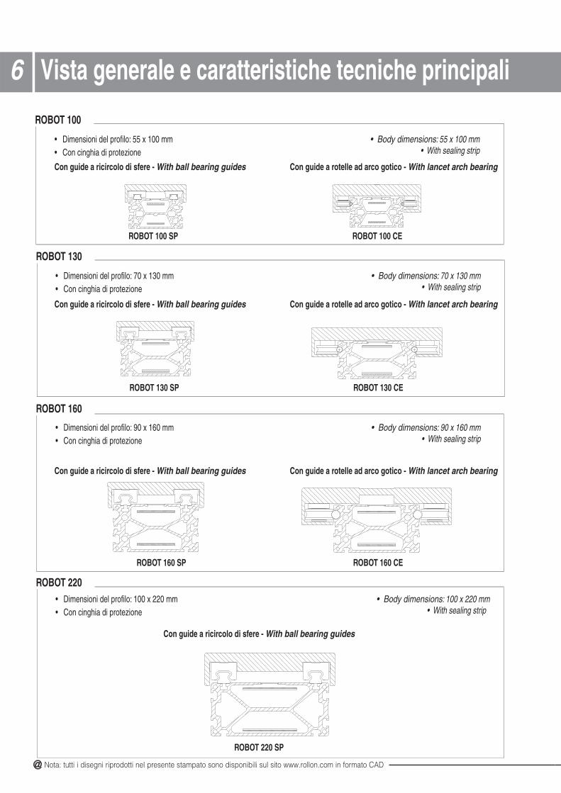
• Dimensioni del profilo: 70 x 130 mm• Con cinghia di protezione
ROBOT 130 SP
• Dimensioni del profilo: 90 x 160 mm• Con cinghia di protezione
EC 061 TOBORPS 061 TOBOR
• Dimensioni del profilo: 100 x 220 mm• Con cinghia di protezione
ROBOT 220 SP
ROBOT 220
ROBOT 130
ROBOT 160
• Dimensioni del profilo: 55 x 100 mm• Con cinghia di protezione
• Body dimensions: 70 x 130 mm• With sealing strip
• Body dimensions: 90 x 160 mm• With sealing strip
• Body dimensions: 100 x 220 mm• With sealing strip
• Body dimensions: 55 x 100 mm• With sealing strip
ROBOT 100 SP
Con guide a ricircolo di sfere - With ball bearing guides Con guide a rotelle ad arco gotico - With lancet arch bearing
Con guide a ricircolo di sfere - With ball bearing guides Con guide a rotelle ad arco gotico - With lancet arch bearing
Con guide a ricircolo di sfere - With ball bearing guides Con guide a rotelle ad arco gotico - With lancet arch bearing
ROBOT 100 CE
ROBOT 100
Con guide a ricircolo di sfere - With ball bearing guides
ROBOT 130 CE
Vista generale e caratteristiche tecniche principali
@ All the drawings in this catalogue are available in CAD files on www.rollon.com
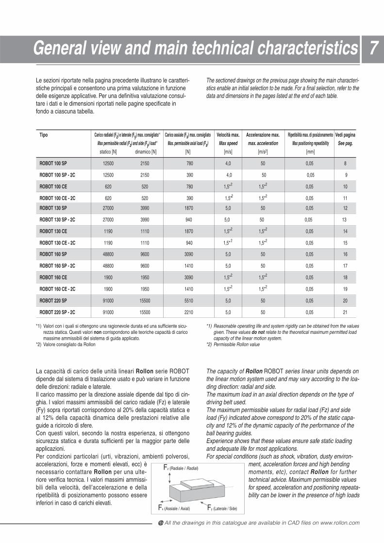
Le sezioni riportate nella pagina precedente illustrano le caratteri-stiche principali e consentono una prima valutazione in funzionedelle esigenze applicative. Per una definitiva valutazione consul-tare i dati e le dimensioni riportati nelle pagine specificate infondo a ciascuna tabella.
The sectioned drawings on the previous page showing the main characteri-stics enable an initial selection to be made. For a final selection, refer to thedata and dimensions in the pages listed at the end of each table.
77General view and main technical characteristics
Tipo Carico radialel (Fz) e laterale (Fy) max. consigliato*1 Carico assiale (Fx) max. consigliato Velocità max. Accelerazione max. Ripetibilità max. di posizionamento Vedi pagina
Max permissible radial (Fz) and side (Fy) load*1 Max. permissible axial load (Fx) Max speed max. acceleration Max positioning repeatibility See pag.
statico [N] dinamico [N] [N] [m/s] [m/s2] [mm]
ROBOT 100 SP 12500 2150 780 4,0 50 0,05 8
ROBOT 100 SP - 2C 12500 2150 390 4,0 50 0,05 9
ROBOT 100 CE 620 520 780 1,5*2 1,5*2 0,05 10
ROBOT 100 CE - 2C 620 520 390 1,5*2 1,5*2 0,05 11
*1) Valori con i quali si ottengono una ragionevole durata ed una sufficiente sicu-rezza statica. Questi valori non corrispondono alle teoriche capacità di caricomassime ammissibili del sistema di guida applicato.
*2) Valore consigliato da Rollon
*1) Reasonable operating life and system rigidity can be obtained from the valuesgiven. These values do not relate to the theoretical maximum permitted loadcapacity of the linear motion system.
*2) Permissible Rollon value
ROBOT 130 SP 27000 3990 1870 5,0 50 0,05 12
ROBOT 130 SP - 2C 27000 3990 940 5,0 50 0,05 13
ROBOT 130 CE 1190 1110 1870 1,5*2 1,5*2 0,05 14
ROBOT 130 CE - 2C 1190 1110 940 1,5* 2 1,5*2 0,05 15
ROBOT 160 SP 48800 9600 3090 5,0 50 0,05 16
ROBOT 160 SP - 2C 48800 9600 1410 5,0 50 0,05 17
ROBOT 160 CE 1900 1950 3090 1,5*2 1,5*2 0,05 18
ROBOT 160 CE - 2C 1900 1950 1410 1,5*2 1,5*2 0,05 19
ROBOT 220 SP 91000 15500 5510 5,0 50 0,05 20
ROBOT 220 SP - 2C 91000 15500 2210 5,0 50 0,05 21
La capacità di carico delle unità lineari Rollon serie ROBOT dipende dal sistema di traslazione usato e può variare in funzionedelle direzioni: radiale e laterale.Il carico massimo per la direzione assiale dipende dal tipo di cin-ghia. I valori massimi ammissibili del carico radiale (Fz) e laterale(Fy) sopra riportati corrispondono al 20% della capacità statica eal 12% della capacità dinamica delle prestazioni relative alleguide a ricircolo di sfere.Con questi valori, secondo la nostra esperienza, si ottengonosicurezza statica e durata sufficienti per la maggior parte delleapplicazioni.Per condizioni particolari (urti, vibrazioni, ambienti polverosi,accelerazioni, forze e momenti elevati, ecc) ènecessario contattare Rollon per una ulte- riore verifica tecnica. I valori massimi ammissi-bili della velocità, dell’accelerazione e dellaripetibilità di posizionamento possono essereinferiori in caso di carichi elevati.
The capacity of Rollon ROBOT series linear units depends on the linear motion system used and may vary according to the loa-ding direction: radial and side.The maximum load in an axial direction depends on the type ofdriving belt used.The maximum permissible values for radial load (Fz) and sideload (Fy) indicated above correspond to 20% of the static capa-city and 12% of the dynamic capacity of the performance of theball bearing guides.Experience shows that these values ensure safe static loadingand adequate life for most applications.For special conditions (such as shock, vibration, dusty environ-
ment, acceleration forces and high bendingmoments, etc), contact Rollon for further technical advice. Maximum permissible valuesfor speed, acceleration and positioning repeata-bility can be lower in the presence of high loads
Fz (Radiale / Radial)
Fx (Assiale / Axial) Fy (Laterale / Side)
@ Nota: tutti i disegni riprodotti nel presente stampato sono disponibili sul sito www.rollon.com in formato CAD
88
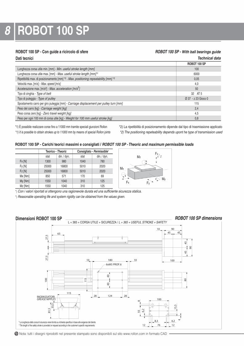
Dimensioni ROBOT 100 SP
ROBOT 100 SP - Con guide a ricircolo di sfereDati tecnici
ROBOT 100 SP - With ball bearings guide
Technical dataROBOT 100 SP
Lunghezza corsa utile min. [mm] - Min. useful stroke length [mm] 100Lunghezza corsa utile max. [mm] - Max. useful stroke length [mm]*1 6000Ripetibilità max. di posizionamento [mm] *2 - Max. positioning repeatability [mm] *2 0,05Velocità max. [m/s] - Max. speed [m/s] 4,0Accelerazione max. [m/s2] - Max. acceleration [m/s2] 50Tipo di cinghia - Type of belt 32 AT 5Tipo di puleggia - Type of pulley Ø 37 - z 23 Gioco 0Spostamento carro per giro puleggia [mm] - Carriage displacement per pulley turn [mm] 115Peso del carro [kg] - Carriage weight [kg] 2,4Peso corsa zero [kg] - Zero travel weight [kg] 4,5Peso per ogni 100 mm di corsa utile [kg] - Weight for 100 mm useful stroke [kg] 0,8
*1) È possibile realizzare corse fino a 11000 mm tramite speciali giunzioni Rollon *2) La ripetibilità di posizionamento dipende dal tipo di trasmissione applicato*1) It is possible to obtain strokes up to 11000 mm by means of special Rollon joints *2) The positioning repeteability depends upont he type of transmission used
Teorico - Theoric Consigliato - Permissible*
stat din. / dyn. stat din. / dyn.Fx [N] 1300 980 1040 780Fy [N] 25000 16800 5010 2020Fz [N] 25000 16800 5010 2020Mx [Nm] 850 571 170 69My [Nm] 1550 1040 310 125Mz [Nm] 1550 1040 310 125
ROBOT 100 SP dimensions
*) Con i valori riportati si ottengono una ragionevole durata ed una sufficiente sicurezza statica.*) Reasonable operating life and system rigidity can be obtained from the values given.
ROBOT 100 SP - Carichi teorici massimi e consigliati / ROBOT 100 SP - Theoric and maximum permissible loads
Fx
MzFz
Mx
FyMy
ROBOT 100 SP
4040
6xM5 PROF.6
INGRASSATORIGREASE NIPPLES
9010
90
100
65
80
1018010
115
28 124 28
100
115
100
55 6,2
12 76 12
8,3 4,2 4
15,5
8
81,5
33,5
27,5
27,5
4545
4545
ROBOT 100 NTS
L = 365 + CORSA UTILE + SICUREZZA / L = 365 + USEFUL STROKE + SAFETY
* La lunghezza della corsa di sicurezza viene fornita su richiesta specifica in base alle esigenze del cliente.* The length of the safety stroke is provided on request according to the customer's specific requirements.
@ All the drawings in this catalogue are available in CAD files on www.rollon.com
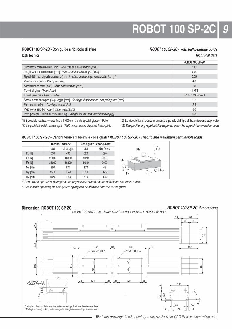
99ROBOT 100 SP-2C
ROBOT 100 SP-2CLunghezza corsa utile min. [mm] - Min. useful stroke length [mm] 100Lunghezza corsa utile max. [mm] - Max. useful stroke length [mm]*1 6000Ripetibilità max. di posizionamento [mm] *2 - Max. positioning repeatability [mm] *2 0,05Velocità max. [m/s] - Max. speed [m/s] 4,0Accelerazione max. [m/s2] - Max. acceleration [m/s2] 50Tipo di cinghia - Type of belt 16 AT 5Tipo di puleggia - Type of pulley Ø 37 - z 23 Gioco 0Spostamento carro per giro puleggia [mm] - Carriage displacement per pulley turn [mm] 115Peso del carro [kg] - Carriage weight [kg] 2,4Peso corsa zero [kg] - Zero travel weight [kg] 8,0Peso per ogni 100 mm di corsa utile [kg] - Weight for 100 mm useful stroke [kg] 0,8
*1) È possibile realizzare corse fino a 11000 mm tramite speciali giunzioni Rollon *2) La ripetibilità di posizionamento dipende dal tipo di trasmissione applicato*1) It is posible to obtain strokes up to 11000 mm by means of special Rollon joints *2) The positioning repeteability depends upont he type of transmission used
Dimensioni ROBOT 100 SP-2C
Teorico - Theoric Consigliato - Permissible*
stat din. / dyn. stat din. / dyn.Fx [N] 650 490 520 390Fy [N] 25000 16800 5010 2020Fz [N] 25000 16800 5010 2020Mx [Nm] 850 571 170 69My [Nm] 1550 1040 310 125Mz [Nm] 1550 1040 310 125
Fx
MzFz
Mx
FyMy
*) Con i valori riportati si ottengono una ragionevole durata ed una sufficiente sicurezza statica.*) Reasonable operating life and system rigidity can be obtained from the values given.
ROBOT 100 SP-2C - Carichi teorici massimi e consigliati / ROBOT 100 SP -2C - Theoric and maximum permissible loads
ROBOT 100 SP-2C dimensions
4040
4040
6xM5 PROF.6 6xM5 PROF.6
INGRASSATORIGREASE NIPPLES
ROBOT 100 NTS 2C
9010
90
100
65
100
10 180 10 180 10
28 124 28 28 124 28
80
27,5
27,5
4545
45 45
115
100
55 6,2
12 76 12
8,3 4,2 4
15,5
8
115
81,5
33,5
L = 555 + CORSA UTILE + SICUREZZA / L = 555 + USEFUL STROKE + SAFETY
* La lunghezza della corsa di sicurezza viene fornita su richiesta specifica in base alle esigenze del cliente.* The length of the safety stroke is provided on request according to the customer's specific requirements.
ROBOT 100 SP-2C - With ball bearings guide
Technical data
ROBOT 100 SP-2C - Con guide a ricircolo di sfereDati tecnici
@ Nota: tutti i disegni riprodotti nel presente stampato sono disponibili sul sito www.rollon.com in formato CAD
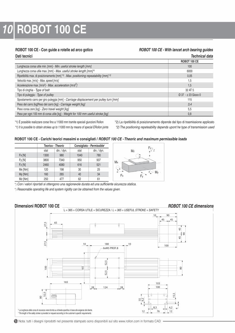
ROBOT 100 CE - Con guide a rotelle ad arco goticoDati tecnici
ROBOT 100 CE - With lancet arch bearing guidesTechnical data
ROBOT 100 CELunghezza corsa utile min. [mm] - Min. useful stroke length [mm] 100Lunghezza corsa utile max. [mm] - Max. useful stroke length [mm]*1 6000Ripetibilità max. di posizionamento [mm] *2 - Max. positioning repeatability [mm] *2 0,05Velocità max. [m/s] - Max. speed [m/s] 1,5Accelerazione max. [m/s2] - Max. acceleration [m/s2] 1,5Tipo di cinghia - Type of belt 32 AT 5Tipo di puleggia - Type of pulley Ø 37 - z 23 Gioco 0Spostamento carro per giro puleggia [mm] - Carriage displacement per pulley turn [mm] 115Peso del carro [kg]Peso del carro [kg] - 4,3]gk[ thgiew egairraCPeso corsa zero [kg] - Zero travel weight [kg] 5,5Peso per ogni 100 mm di corsa utile [kg] - Weight for 100 mm useful stroke [kg] 0,8
*1) È possibile realizzare corse fino a 11000 mm tramite speciali giunzioni Rollon *2) La ripetibilità di posizionamento dipende dal tipo di trasmissione applicato*1) It is possible to obtain strokes up to 11000 mm by means of special ERollon joints *2) The positioning repeteability depends upont he type of transmission used
Dimensioni ROBOT 100 CE
Teorico - Theoric Consigliato - Permissible*
stat din. / dyn. stat din. / dyn.Fx [N] 1300 980 1040 780Fy [N] 3800 7340 950 937Fz [N] 2460 4080 616 521Mx [Nm] 120 198 30 25My [Nm] 160 265 40 34Mz [Nm] 250 477 62 61
ROBOT 100 CE dimensions
Fx
MzFz
Mx
FyMy
*) Con i valori riportati si ottengono una ragionevole durata ed una sufficiente sicurezza statica.*) Reasonable operating life and system rigidity can be obtained from the values given.
ROBOT 100 CE - Carichi teorici massimi e consigliati / ROBOT 100 CE - Theoric and maximum permissible loads
1010 ROBOT 100 CE
52,5
52,5
6xM5 PROF.8
103
ROBOT 100 CE
90
100
9010
80100
65
1018010
165
28 124 28
165
100
55
12 76 12
4,28,3
6,2
415
,5
80
52,5
27,5
27,5
45 45
4545
L = 365 + CORSA UTILE + SICUREZZA / L = 365 + USEFUL STROKE + SAFETY
* La lunghezza della corsa di sicurezza viene fornita su richiesta specifica in base alle esigenze del cliente.* The length of the safety stroke is provided on request according to the customer's specific requirements.
@ All the drawings in this catalogue are available in CAD files on www.rollon.com
11
4545
ROBOT 100 CE-2C
Dimensioni ROBOT 100 CE-2C
ROBOT 100 CE-2C - Con guide a rotelle ad arco goticoDati tecnici
ROBOT 100 CE-2C - With lancet arch bearing guidesTechnical data
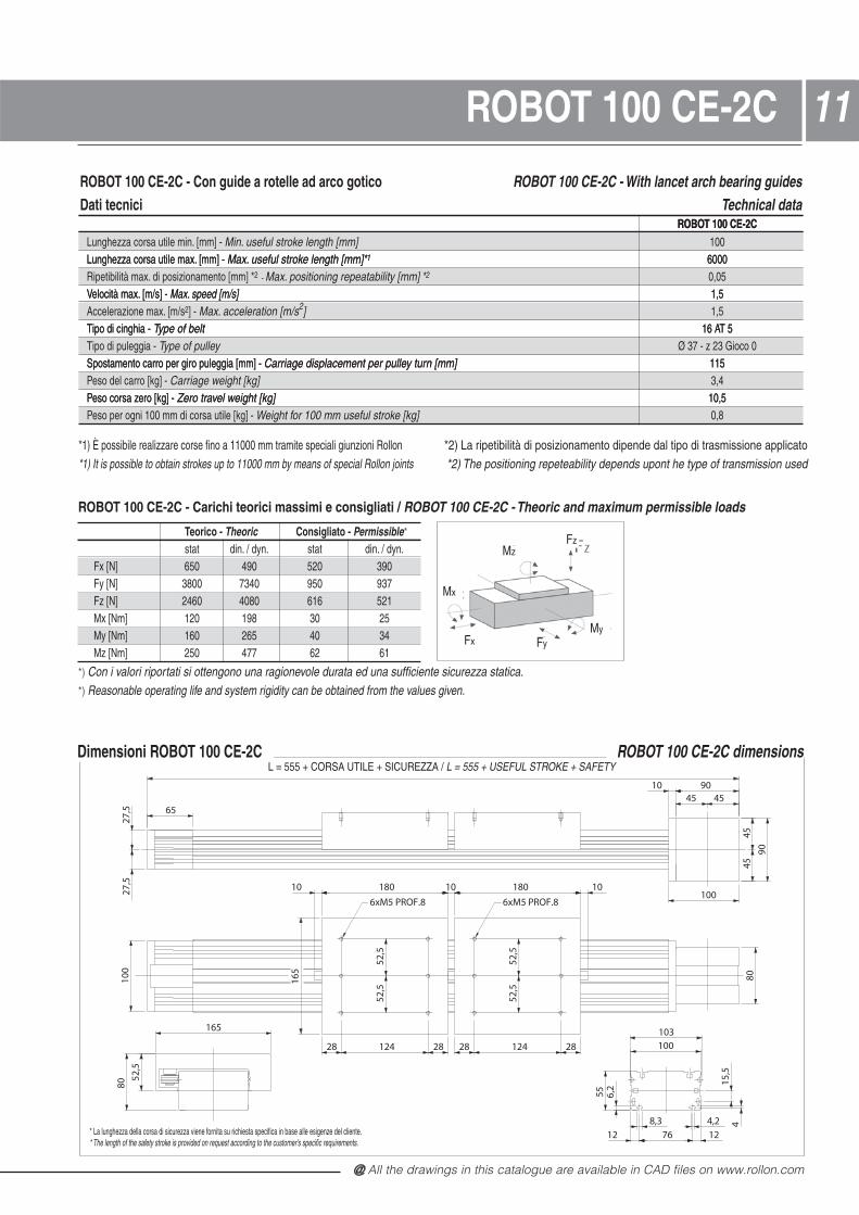
ROBOT 100 CE-2CLunghezza corsa utile min. [mm] - Min. useful stroke length [mm] 100Lunghezza corsa utile max. [mm] - Max. useful stroke length [mm]*1 6000Ripetibilità max. di posizionamento [mm] *2 - Max. positioning repeatability [mm] *2 0,05Velocità max. [m/s] - Max. speed [m/s] 1,5Accelerazione max. [m/s2] - Max. acceleration [m/s2] 1,5Tipo di cinghia - Type of belt 16 AT 5Tipo di puleggia - Type of pulley Ø 37 - z 23 Gioco 0Spostamento carro per giro puleggia [mm] - Carriage displacement per pulley turn [mm] 115Peso del carro [kg] - Carriage weight [kg] 3,4Peso corsa zero [kg] - Zero travel weight [kg] 10,5
ROBOT 100 CE-2CLunghezza corsa utile min. [mm] - Min. useful stroke length [mm] 100Lunghezza corsa utile max. [mm] - Max. useful stroke length [mm]*1 6000Ripetibilità max. di posizionamento [mm] *2 - Max. positioning repeatability [mm] *2 0,05Velocità max. [m/s] - Max. speed [m/s] 1,5Accelerazione max. [m/s2] - Max. acceleration [m/s2] 1,5Tipo di cinghia - Type of belt 16 AT 5Tipo di puleggia - Type of pulley Ø 37 - z 23 Gioco 0Spostamento carro per giro puleggia [mm] - Carriage displacement per pulley turn [mm] 115Peso del carro [kg] - Carriage weight [kg] 3,4Peso corsa zero [kg] - Zero travel weight [kg] 10,5Peso per ogni 100 mm di corsa utile [kg] - Weight for 100 mm useful stroke [kg] 0,8
*1) È possibile realizzare corse fino a 11000 mm tramite speciali giunzioni Rollon *2) La ripetibilità di posizionamento dipende dal tipo di trasmissione applicato*1) It is possible to obtain strokes up to 11000 mm by means of special Rollon joints *2) The positioning repeteability depends upont he type of transmission used
Teorico - Theoric Consigliato - Permissible*
stat din. / dyn. stat din. / dyn.Fx [N] 650 490 520 390Fy [N] 3800 7340 950 937Fz [N] 2460 4080 616 521Mx [Nm] 120 198 30 25My [Nm] 160 265 40 34Mz [Nm] 250 477 62 61
Fx
MzFz
Mx
FyMy
*) Con i valori riportati si ottengono una ragionevole durata ed una sufficiente sicurezza statica.*) Reasonable operating life and system rigidity can be obtained from the values given.
ROBOT 100 CE-2C - Carichi teorici massimi e consigliati / ROBOT 100 CE-2C - Theoric and maximum permissible loads
6xM5 PROF.8
52,5
52,5
6xM5 PROF.8
52,5
52,5
103
ROBOT 100 CE 2C
9010
90
100
65
100
10 180 10 180 10
28 124 28 28 124 28
80
27,5
27,5
45 45
4545
165
80
52,5
165
100
55
12 76 12
4,28,3
6,2
415
,5
L = 555 + CORSA UTILE + SICUREZZA / L = 555 + USEFUL STROKE + SAFETY
* La lunghezza della corsa di sicurezza viene fornita su richiesta specifica in base alle esigenze del cliente.* The length of the safety stroke is provided on request according to the customer's specific requirements.
ROBOT 100 CE-2C dimensions
@ Nota: tutti i disegni riprodotti nel presente stampato sono disponibili sul sito www.rollon.com in formato CAD
*1) È possibile realizzare corse fino a 11000 mm tramite speciali giunzioni Rollon *2) La ripetibilità di posizionamento dipende dal tipo di trasmissione applicato*2) The positioning repeteability depends upont he type of transmission used*1) It is posible to obtain strokes up to 11000 mm by means of special Rollon joints
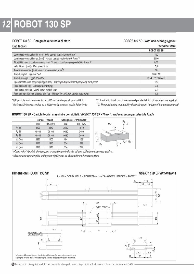
ROBOT 130 SP - Con guide a ricircolo di sfereDati tecnici
ROBOT 130 SP - With ball bearings guide
Technical dataROBOT 130 SP
Lunghezza corsa utile min. [mm] - Min. useful stroke length [mm] 100Lunghezza corsa utile max. [mm]*1 - Max. useful stroke length [mm]*1 6000Ripetibilità max. di posizionamento [mm] *2 - Max. positioning repeatability [mm] *2 0,05Velocità max. [m/s] - Max. speed [m/s] 5,0Accelerazione max. [m/s2] - Max. acceleration [m/s2] 50Tipo di cinghia - Type of belt 50 AT 10Tipo di puleggia - Type of pulley Ø 54 - z 17 Gioco 0Spostamento carro per giro puleggia [mm] - Carriage displacement per pulley turn [mm] 170Peso del carro [kg] - Carriage weight [kg] 2,8Peso corsa zero [kg] - Zero travel weight [kg] 9,1Peso per ogni 100 mm di corsa utile [kg] - Weight for 100 mm useful stroke [kg] 1,2
Dimensioni ROBOT 130 SP
Teorico - Theoric Consigliato - Permissible*
stat din. / dyn. stat din. / dyn.Fx [N] 3120 2340 2500 1870Fy [N] 48400 29100 9680 3490Fz [N] 48400 29100 9680 3490Mx [Nm] 2320 1400 464 168My [Nm] 3170 1910 634 229Mz [Nm] 3170 1910 634 229
ROBOT 130 SP dimensions
Fx
MzFz
Mx
FyMy
*) Con i valori riportati si ottengono una ragionevole durata ed una sufficiente sicurezza statica.*) Reasonable operating life and system rigidity can be obtained from the values given.
ROBOT 130 SP - Carichi teorici massimi e consigliati / ROBOT 130 SP - Theoric and maximum permissible loads
1212 ROBOT 130 SP
4848
6xM6 PROF.10
37,5 37,5155
12014
120
134
95
110
1023010
145
130
145
130
70 9,5
13,2 8,2
17 96 17
61810
338
3535
60 60
6060
ROBOT 130 NTS
INGRASSATORIGREASE NIPPLES
L = 479 + CORSA UTILE + SICUREZZA / L = 479 + USEFUL STROKE + SAFETY
* La lunghezza della corsa di sicurezza viene fornita su richiesta specifica in base alle esigenze del cliente.* The length of the safety stroke is provided on request according to the customer's specific requirements.

@ All the drawings in this catalogue are available in CAD files on www.rollon.com
13ROBOT 130 SP-2C
ROBOT 130 SP-2CLunghezza corsa utile min. [mm] - Min. useful stroke length [mm] 100Lunghezza corsa utile max. [mm]*1 - Max. useful stroke length [mm]*1 6000Ripetibilità max. di posizionamento [mm] *2 - Max. positioning repeatability [mm] *2 0,05Velocità max. [m/s] - Max. speed [m/s] 5,0Accelerazione max. [m/s2] - Max. acceleration [m/s2] 50Tipo di cinghia - Type of belt 25 AT 10Tipo di puleggia - Type of pulley Ø 54 - z 17 Gioco 0Spostamento carro per giro puleggia [mm] - Carriage displacement per pulley turn [mm] 170Peso del carro [kg] - Carriage weight [kg] 2,8Peso corsa zero [kg] - Zero travel weight [kg] 14,9Peso per ogni 100 mm di corsa utile [kg] - Weight for 100 mm useful stroke [kg] 1,2
Dimensioni ROBOT 130 SP-2C
Teorico - Theoric Consigliato - Permissible*
stat din. / dyn. stat din. / dyn.Fx [N] 1560 1170 1250 940Fy [N] 48400 29100 9680 3490Fz [N] 48400 29100 9680 3490Mx [Nm] 2320 1400 464 168My [Nm] 3170 1910 634 229Mz [Nm] 3170 1910 634 229
*1) È possibile realizzare corse fino a 11000 mm tramite speciali giunzioni Rollon *2) La ripetibilità di posizionamento dipende dal tipo di trasmissione applicato*1) It is possible to obtain strokes up to 11000 mm by means of special Rollon joints *2) The positioning repeteability depends upont he type of transmission used
Fx
MzFz
Mx
FyMy
*) Con i valori riportati si ottengono una ragionevole durata ed una sufficiente sicurezza statica.*) Reasonable operating life and system rigidity can be obtained from the values given.
ROBOT 130 SP-2C - Carichi teorici massimi e consigliati / ROBOT 130 SP -2C - Theoric and maximum permissible loads
ROBOT 130 SP-2C dimensions
10 230 10 230 10
4848
6xM6 PROF.10
4848
6xM6 PROF.10
37,5 37,5 37,5 37,5155 155
14 120
120
134
95
130
110
145
3535
60 60
6060
ROBOT 130 NTS 2C
145
103
38
130
70 9,5
13,2 8,2
17 96 17
618
INGRASSATORIGREASE NIPPLES
L = 719 + CORSA UTILE + SICUREZZA / L = 719 + USEFUL STROKE + SAFETY
* La lunghezza della corsa di sicurezza viene fornita su richiesta specifica in base alle esigenze del cliente.* The length of the safety stroke is provided on request according to the customer's specific requirements.
ROBOT 130 SP-2C - Con guide a ricircolo di sfereDati tecnici
ROBOT 130 SP-2C - With ball bearings guide
Technical data
@ Nota: tutti i disegni riprodotti nel presente stampato sono disponibili sul sito www.rollon.com in formato CAD
ROBOT 130 CE - With lancet arch bearing guidesTechnical data
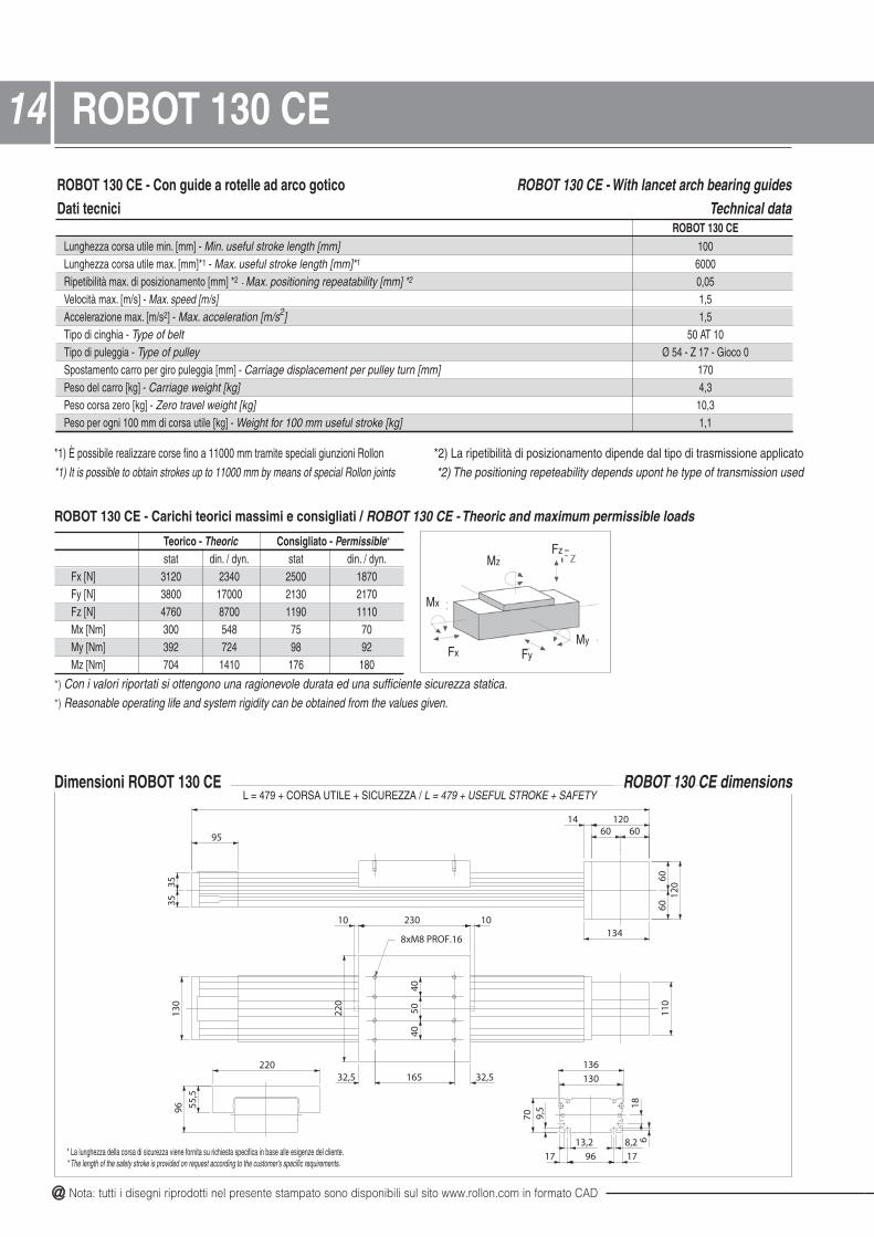
ROBOT 130 CE - Con guide a rotelle ad arco goticoDati tecnici
ROBOT 130 CELunghezza corsa utile min. [mm] - Min. useful stroke length [mm] 100Lunghezza corsa utile max. [mm]*1 - Max. useful stroke length [mm]*1 6000Ripetibilità max. di posizionamento [mm] *2 - Max. positioning repeatability [mm] *2 0,05Velocità max. [m/s] - Max. speed [m/s] 1,5Accelerazione max. [m/s2] - Max. acceleration [m/s2] 1,5Tipo di cinghia - Type of belt 50 AT 10Tipo di puleggia - Type of pulley Ø 54 - Z 17 - Gioco 0Spostamento carro per giro puleggia [mm] - Carriage displacement per pulley turn [mm] 170Peso del carro [kg] - Carriage weight [kg] 4,3Peso corsa zero [kg] - Zero travel weight [kg] 10,3Peso per ogni 100 mm di corsa utile [kg] - Weight for 100 mm useful stroke [kg] 1,1
Dimensioni ROBOT 130 CE
Teorico - Theoric Consigliato - Permissible*
stat din. / dyn. stat din. / dyn.Fx [N] 3120 2340 2500 1870Fy [N] 3800 17000 2130 2170Fz [N] 4760 8700 1190 1110Mx [Nm] 300 548 75 70My [Nm] 392 724 98 92Mz [Nm] 704 1410 176 180
*1) È possibile realizzare corse fino a 11000 mm tramite speciali giunzioni Rollon *2) La ripetibilità di posizionamento dipende dal tipo di trasmissione applicato*1) It is possible to obtain strokes up to 11000 mm by means of special Rollon joints *2) The positioning repeteability depends upont he type of transmission used
ROBOT 130 CE dimensions
Fx
MzFz
Mx
FyMy
*) Con i valori riportati si ottengono una ragionevole durata ed una sufficiente sicurezza statica.*) Reasonable operating life and system rigidity can be obtained from the values given.
ROBOT 130 CE - Carichi teorici massimi e consigliati / ROBOT 130 CE - Theoric and maximum permissible loads
1414 ROBOT 130 CE
4050
40
32,5 32,5165
8xM8 PROF.16
136
120
12014
134
95
110
1023010
220
130
3535
60 60
6060
ROBOT 130 CE
130
70 9,5
17 96 17
13,2 8,2 618
220
96 55,5
L = 479 + CORSA UTILE + SICUREZZA / L = 479 + USEFUL STROKE + SAFETY
* La lunghezza della corsa di sicurezza viene fornita su richiesta specifica in base alle esigenze del cliente.* The length of the safety stroke is provided on request according to the customer's specific requirements.

@ All the drawings in this catalogue are available in CAD files on www.rollon.com
15ROBOT 130 CE-2C
ROBOT 130 CE-2C - Con guide a rotelle ad arco goticoDati tecnici
ROBOT 130 CE-2C - With lancet arch bearing guidesTechnical data
ROBOT 130 CE-2CLunghezza corsa utile min. [mm] - Min. useful stroke length [mm] 100Lunghezza corsa utile max. [mm]*1 - Max. useful stroke length [mm]*1 6000Ripetibilità max. di posizionamento [mm] *2 - Max. positioning repeatability [mm] *2 0,05Velocità max. [m/s] - Max. speed [m/s] 1,5Accelerazione max. [m/s2] - Max. acceleration [m/s2] 1,5Tipo di cinghia - Type of belt 25 AT 10Tipo di puleggia - Type of pulley Ø 54 - Z 17 - Gioco 0Spostamento carro per giro puleggia [mm] - Carriage displacement per pulley turn [mm] 170Peso del carro [kg] - Carriage weight [kg] 4,3Peso corsa zero [kg] - Zero travel weight [kg] 17,4Peso per ogni 100 mm di corsa utile [kg] - Weight for 100 mm useful stroke [kg] 1,1
Dimensioni ROBOT 130 CE-2C
Teorico - Theoric Consigliato - Permissible*
stat din. / dyn. stat din. / dyn.Fx [N] 1560 1170 1250 940Fy [N] 3800 17000 2130 2170Fz [N] 4760 8700 1190 1110Mx [Nm] 300 548 75 70My [Nm] 392 724 98 92Mz [Nm] 704 1410 176 180
*1) È possibile realizzare corse fino a 11000 mm tramite speciali giunzioni Rollon *2) La ripetibilità di posizionamento dipende dal tipo di trasmissione applicato*1) It is possible to obtain strokes up to 11000 mm by means of special Rollon joints *2) The positioning repeteability depends upont he type of transmission used
L = 719+ CORSA UTILE + SICUREZZA / L = 719 + USEFUL STROKE + SAFETY
Fx
MzFz
Mx
FyMy
*) Con i valori riportati si ottengono una ragionevole durata ed una sufficiente sicurezza statica.*) Reasonable operating life and system rigidity can be obtained from the values given.
ROBOT 130 CE-2C - Carichi teorici massimi e consigliati / ROBOT 130 CE-2C - Theoric and maximum permissible loads
ROBOT 130 CE-2C dimensions
8xM8 PROF.16
4050
40
32,5 32,5165
8xM8 PROF.16
4050
40
32,5 32,5165
10 230 230 1010
136130
70 9,5
17 96 1713,2 8,2 6
18
220
120
12014
134
95
110
220
130
96 55,5
3535
60 60
6060
ROBOT 130 CE - 2C
* La lunghezza della corsa di sicurezza viene fornita su richiesta specifica in base alle esigenze del cliente.* The length of the safety stroke is provided on request according to the customer's specific requirements.
@ Nota: tutti i disegni riprodotti nel presente stampato sono disponibili sul sito www.rollon.com in formato CAD
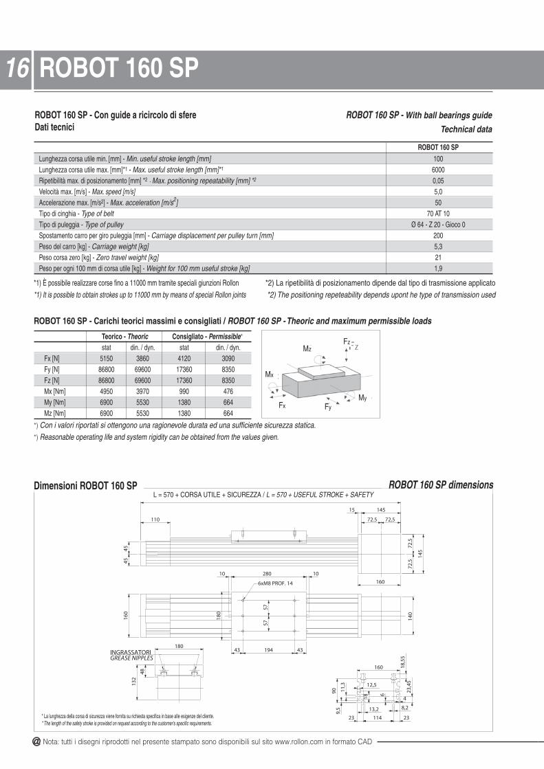
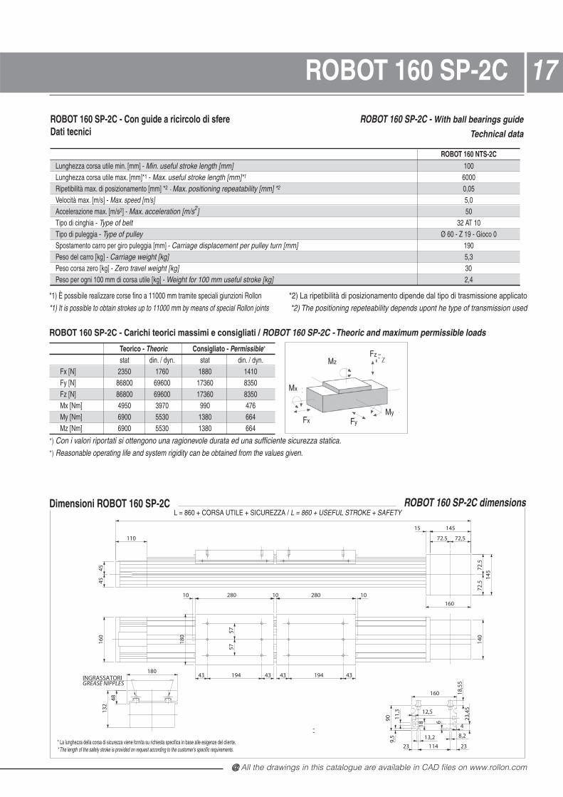
ROBOT 160 SP - Con guide a ricircolo di sfere Dati tecnici
ROBOT 160 SP - With ball bearings guide
Technical data
ROBOT 160 SPLunghezza corsa utile min. [mm] - Min. useful stroke length [mm] 100Lunghezza corsa utile max. [mm]*1 - Max. useful stroke length [mm]*1 6000Ripetibilità max. di posizionamento [mm] *2 - Max. positioning repeatability [mm] *2 0,05Velocità max. [m/s] - Max. speed [m/s] 5,0Accelerazione max. [m/s2] - Max. acceleration [m/s2] 50Tipo di cinghia - Type of belt 70 AT 10Tipo di puleggia - Type of pulley Ø 64 - Z 20 - Gioco 0Spostamento carro per giro puleggia [mm] - Carriage displacement per pulley turn [mm] 200Peso del carro [kg] - Carriage weight [kg] 5,3Peso corsa zero [kg] - Zero travel weight [kg] 21Peso per ogni 100 mm di corsa utile [kg] - Weight for 100 mm useful stroke [kg] 1,9
Dimensioni ROBOT 160 SP
Teorico - Theoric Consigliato - Permissible*
stat din. / dyn. stat din. / dyn.Fx [N] 5150 3860 4120 3090Fy [N] 86800 69600 17360 8350Fz [N] 86800 69600 17360 8350Mx [Nm] 4950 3970 990 476My [Nm] 6900 5530 1380 664Mz [Nm] 6900 5530 1380 664
*1) È possibile realizzare corse fino a 11000 mm tramite speciali giunzioni Rollon *2) La ripetibilità di posizionamento dipende dal tipo di trasmissione applicato*1) It is possible to obtain strokes up to 11000 mm by means of special Rollon joints *2) The positioning repeteability depends upont he type of transmission used
ROBOT 160 SP dimensions
Fx
MzFz
Mx
FyMy
*) Con i valori riportati si ottengono una ragionevole durata ed una sufficiente sicurezza statica.*) Reasonable operating life and system rigidity can be obtained from the values given.
ROBOT 160 SP - Carichi teorici massimi e consigliati / ROBOT 160 SP - Theoric and maximum permissible loads
1616 ROBOT 160 SP
6xM8 PROF. 14
5757
180
145
14515
160
110
140
160
1028010
180
43 194 43
132
48
4545
72,572.5
72.5
72.5
ROBOT 160 SP
160
909,
5
23 114 23
13,2 8,2
23,4
5
11,3
18
12,5
4
6
18,5
5
INGRASSATORIGREASE NIPPLES
L = 570 + CORSA UTILE + SICUREZZA / L = 570 + USEFUL STROKE + SAFETY
* La lunghezza della corsa di sicurezza viene fornita su richiesta specifica in base alle esigenze del cliente.* The length of the safety stroke is provided on request according to the customer's specific requirements.
@ All the drawings in this catalogue are available in CAD files on www.rollon.com
17ROBOT 160 SP-2C
ROBOT 160 SP-2C - Con guide a ricircolo di sfereDati tecnici
ROBOT 160 SP-2C - With ball bearings guide
Technical data
Dimensioni ROBOT 160 SP-2C
Teorico - Theoric Consigliato - Permissible*
stat din. / dyn. stat din. / dyn.Fx [N] 2350 1760 1880 1410Fy [N] 86800 69600 17360 8350Fz [N] 86800 69600 17360 8350Mx [Nm] 4950 3970 990 476My [Nm] 6900 5530 1380 664Mz [Nm] 6900 5530 1380 664
ROBOT 160 NTS-2CLunghezza corsa utile min. [mm] - Min. useful stroke length [mm] 100Lunghezza corsa utile max. [mm]*1 - Max. useful stroke length [mm]*1 6000Ripetibilità max. di posizionamento [mm] *2 - Max. positioning repeatability [mm] *2 0,05Velocità max. [m/s] - Max. speed [m/s] 5,0Accelerazione max. [m/s2] - Max. acceleration [m/s2] 50Tipo di cinghia - Type of belt 32 AT 10Tipo di puleggia - Type of pulley Ø 60 - Z 19 - Gioco 0Spostamento carro per giro puleggia [mm] - Carriage displacement per pulley turn [mm] 190Peso del carro [kg] - Carriage weight [kg] 5,3Peso corsa zero [kg] - Zero travel weight [kg] 30Peso per ogni 100 mm di corsa utile [kg] - Weight for 100 mm useful stroke [kg] 2,4
*1) È possibile realizzare corse fino a 11000 mm tramite speciali giunzioni Rollon *2) La ripetibilità di posizionamento dipende dal tipo di trasmissione applicato*1) It is possible to obtain strokes up to 11000 mm by means of special Rollon joints *2) The positioning repeteability depends upont he type of transmission used
Fx
MzFz
Mx
FyMy
*) Con i valori riportati si ottengono una ragionevole durata ed una sufficiente sicurezza statica.*) Reasonable operating life and system rigidity can be obtained from the values given.
ROBOT 160 SP-2C - Carichi teorici massimi e consigliati / ROBOT 160 SP-2C - Theoric and maximum permissible loads
ROBOT 160 SP-2C dimensions
5757
110
15 145
160
43 194 43 43 194 43
145
140
160
10 280 10 280 10
4545
72.5 72,5
72.5
72.5
180
132
48
180
ROBOT 160 SP 2C
160
909,
5
23 114 23
13,2 8,2
23,4
5
11,3
18
12,5
4
6
18,5
5
INGRASSATORIGREASE NIPPLES
L = 860 + CORSA UTILE + SICUREZZA / L = 860 + USEFUL STROKE + SAFETY
* La lunghezza della corsa di sicurezza viene fornita su richiesta specifica in base alle esigenze del cliente.* The length of the safety stroke is provided on request according to the customer's specific requirements.
@ Nota: tutti i disegni riprodotti nel presente stampato sono disponibili sul sito www.rollon.com in formato CAD
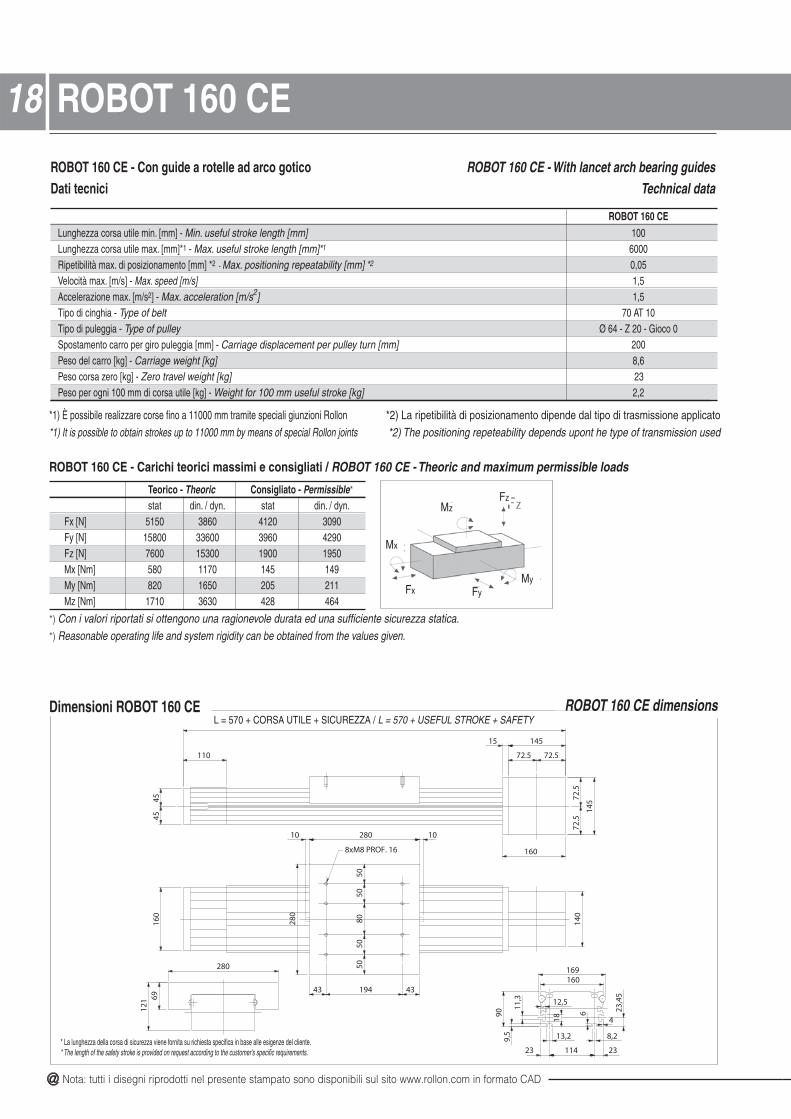
Dimensioni ROBOT 160 CE
ROBOT 160 CE - Con guide a rotelle ad arco goticoDati tecnici
ROBOT 160 CE - With lancet arch bearing guidesTechnical data
Teorico - Theoric Consigliato - Permissible*
stat din. / dyn. stat din. / dyn.Fx [N] 5150 3860 4120 3090Fy [N] 15800 33600 3960 4290Fz [N] 7600 15300 1900 1950Mx [Nm] 580 1170 145 149My [Nm] 820 1650 205 211Mz [Nm] 1710 3630 428 464
ROBOT 160 CELunghezza corsa utile min. [mm] - Min. useful stroke length [mm] 100Lunghezza corsa utile max. [mm]*1 - Max. useful stroke length [mm]*1 6000Ripetibilità max. di posizionamento [mm] *2 - Max. positioning repeatability [mm] *2 0,05Velocità max. [m/s] - Max. speed [m/s] 1,5Accelerazione max. [m/s2] - Max. acceleration [m/s2] 1,5Tipo di cinghia - Type of belt 70 AT 10Tipo di puleggia - Type of pulley Ø 64 - Z 20 - Gioco 0Spostamento carro per giro puleggia [mm] - Carriage displacement per pulley turn [mm] 200Peso del carro [kg] - Carriage weight [kg] 8,6Peso corsa zero [kg] - Zero travel weight [kg] 23Peso per ogni 100 mm di corsa utile [kg] - Weight for 100 mm useful stroke [kg] 2,2
*1) È possibile realizzare corse fino a 11000 mm tramite speciali giunzioni Rollon *2) La ripetibilità di posizionamento dipende dal tipo di trasmissione applicato*1) It is possible to obtain strokes up to 11000 mm by means of special Rollon joints *2) The positioning repeteability depends upont he type of transmission used
ROBOT 160 CE dimensions
Fx
MzFz
Mx
FyMy
*) Con i valori riportati si ottengono una ragionevole durata ed una sufficiente sicurezza statica.*) Reasonable operating life and system rigidity can be obtained from the values given.
ROBOT 160 CE - Carichi teorici massimi e consigliati / ROBOT 160 CE - Theoric and maximum permissible loads
1818 ROBOT 160 CE
8xM8 PROF. 16
5050
8050
50
145
14515
160
110
140
1028010
280
160
280
6912
1
43 194 43
4545
72.572.5
72.5
72.5
ROBOT 160 CE
160169
909,
5
23 114 23
13,2 8,2
23,4
5
418
12,5
11,3
6
L = 570 + CORSA UTILE + SICUREZZA / L = 570 + USEFUL STROKE + SAFETY
* La lunghezza della corsa di sicurezza viene fornita su richiesta specifica in base alle esigenze del cliente.* The length of the safety stroke is provided on request according to the customer's specific requirements.

@ All the drawings in this catalogue are available in CAD files on www.rollon.com
19ROBOT 160 CE-2C
Dimensioni ROBOT 160 CE-2C
ROBOT 160 CE-2C - Con guide a rotelle ad arco goticoDati tecnici
ROBOT 160 CE-2C - With lancet arch bearing guidesTechnical data
Teorico - Theoric Consigliato - Permissible*
stat din. / dyn. stat din. / dyn.Fx [N] 2250 1760 1880 1410Fy [N] 15800 33600 3960 4290Fz [N] 7600 15300 1900 1950Mx [Nm] 580 1170 145 140My [Nm] 820 1650 205 211Mz [Nm] 1710 3630 428 464
*1) È possibile realizzare corse fino a 11000 mm tramite speciali giunzioni Rollon *2) La ripetibilità di posizionamento dipende dal tipo di trasmissione applicato*1) It is possible to obtain strokes up to 11000 mm by means of special Rollon joints *2) The positioning repeteability depends upont he type of transmission used
ROBOT 160 CE-2CLunghezza corsa utile min. [mm] - Min. useful stroke length [mm] 100Lunghezza corsa utile max. [mm]*1 - Max. useful stroke length [mm]*1 6000Ripetibilità max. di posizionamento [mm] *2 - Max. positioning repeatability [mm] *2 0,05Velocità max. [m/s] - Max. speed [m/s] 1,5Accelerazione max. [m/s2] - Max. acceleration [m/s2] 1,5Tipo di cinghia - Type of belt 32 AT 10Tipo di puleggia - Type of pulley Ø 60 - Z 19 - Gioco 0Spostamento carro per giro puleggia [mm] - Carriage displacement per pulley turn [mm] 190Peso del carro [kg] - Carriage weight [kg] 8,6Peso corsa zero [kg] - Zero travel weight [kg] 32Peso per ogni 100 mm di corsa utile [kg] - Weight for 100 mm useful stroke [kg] 2,2
Fx
MzFz
Mx
FyMy
*) Con i valori riportati si ottengono una ragionevole durata ed una sufficiente sicurezza statica.*) Reasonable operating life and system rigidity can be obtained from the values given.
ROBOT 160 CE-2C - Carichi teorici massimi e consigliati / ROBOT 160 CE-2C - Theoric and maximum permissible loads
ROBOT 160 CE-2C dimensions
8xM8 PROF. 16 8xM8 PROF. 16
5050
8050
50
5050
8050
50
145
14515
160
110
140
1028010
160
43 194 43 43 194 43
280 10
4545
72.572.5
72.5
72.5
ROBOT 160 CE 2C
280
6912
1
280
160169
909,
5
23 114 23
13,2 8,2
23,4
5
418
12,5
11,3
6
L = 860 + CORSA UTILE + SICUREZZA / L = 860 + USEFUL STROKE + SAFETY
* La lunghezza della corsa di sicurezza viene fornita su richiesta specifica in base alle esigenze del cliente.* The length of the safety stroke is provided on request according to the customer's specific requirements.
@ Nota: tutti i disegni riprodotti nel presente stampato sono disponibili sul sito www.rollon.com in formato CAD
5660
56
8xM10 PROF. 16
5224
24
2016
11,3
18
3,512
245
2417224
220
14515
160
145
130
1038010
245
55 270 55
220
170
100
ROB
OT
220
RSH
-NTS
155
6150
50
72.5
72.5
72.5 72.5
INGRASSATORIGREASE NIPPLES
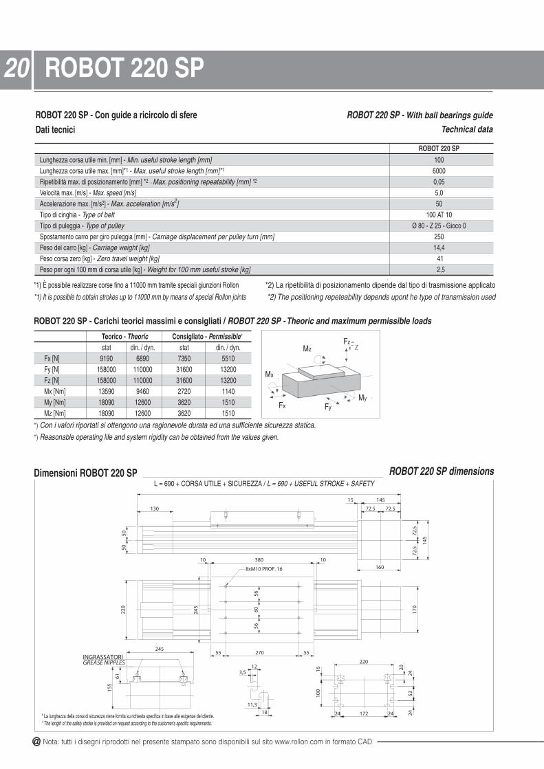
ROBOT 220 SP - Con guide a ricircolo di sfereDati tecnici
ROBOT 220 SP - With ball bearings guide
Technical data
Dimensioni ROBOT 220 SP
Teorico - Theoric Consigliato - Permissible*
stat din. / dyn. stat din. / dyn.Fx [N] 9190 6890 7350 5510Fy [N] 158000 110000 31600 13200Fz [N] 158000 110000 31600 13200Mx [Nm] 13590 9460 2720 1140My [Nm] 18090 12600 3620 1510Mz [Nm] 18090 12600 3620 1510
ROBOT 220 SPLunghezza corsa utile min. [mm] - Min. useful stroke length [mm] 100Lunghezza corsa utile max. [mm]*1 - Max. useful stroke length [mm]*1 6000Ripetibilità max. di posizionamento [mm] *2 - Max. positioning repeatability [mm] *2 0,05Velocità max. [m/s] - Max. speed [m/s] 5,0Accelerazione max. [m/s2] - Max. acceleration [m/s2] 50Tipo di cinghia - Type of belt 100 AT 10Tipo di puleggia - Type of pulley Ø 80 - Z 25 - Gioco 0Spostamento carro per giro puleggia [mm] - Carriage displacement per pulley turn [mm] 250Peso del carro [kg] - Carriage weight [kg] 14,4Peso corsa zero [kg] - Zero travel weight [kg] 41Peso per ogni 100 mm di corsa utile [kg] - Weight for 100 mm useful stroke [kg] 2,5
*1) È possibile realizzare corse fino a 11000 mm tramite speciali giunzioni Rollon *2) La ripetibilità di posizionamento dipende dal tipo di trasmissione applicato*1) It is possible to obtain strokes up to 11000 mm by means of special Rollon joints *2) The positioning repeteability depends upont he type of transmission used
ROBOT 220 SP dimensions
Fx
MzFz
Mx
FyMy
*) Con i valori riportati si ottengono una ragionevole durata ed una sufficiente sicurezza statica.*) Reasonable operating life and system rigidity can be obtained from the values given.
ROBOT 220 SP - Carichi teorici massimi e consigliati / ROBOT 220 SP - Theoric and maximum permissible loads
20 ROBOT 220 SP
L = 690 + CORSA UTILE + SICUREZZA / L = 690 + USEFUL STROKE + SAFETY
* La lunghezza della corsa di sicurezza viene fornita su richiesta specifica in base alle esigenze del cliente.* The length of the safety stroke is provided on request according to the customer's specific requirements.
@ All the drawings in this catalogue are available in CAD files on www.rollon.com
21
Fx
MzFz
Mx
FyMy
*) Con i valori riportati si ottengono una ragionevole durata ed una sufficiente sicurezza statica.*) Reasonable operating life and system rigidity can be obtained from the values given.
ROBOT 220 SP 2C - Carichi teorici massimi e consigliati / ROBOT 220 SP 2C - Theoric and maximum permissible loads
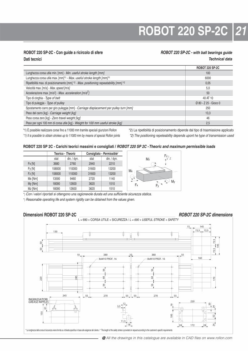
ROBOT 220 SP-2C
ROBOT 220 SP-2C - Con guide a ricircolo di sfereDati tecnici
ROBOT 220 SP-2C - with ball bearings guide
Technical data
Dimensioni ROBOT 220 SP-2C
Teorico - Theoric Consigliato - Permissible*
stat din. / dyn. stat din. / dyn.Fx [N] 3680 2760 2940 2210Fy [N] 158000 110000 31600 13200Fz [N] 158000 110000 31600 13200Mx [Nm] 13590 9460 2720 1140My [Nm] 18090 12600 3620 1510Mz [Nm] 18090 12600 3620 1510
ROBOT 220 SP-2CLunghezza corsa utile min. [mm] - Min. useful stroke length [mm] 100Lunghezza corsa utile max. [mm]*1 - Max. useful stroke length [mm]*1 6000Ripetibilità max. di posizionamento [mm] *2 - Max. positioning repeatability [mm] *2 0,05Velocità max. [m/s] - Max. speed [m/s] 5,0Accelerazione max. [m/s2] - Max. acceleration [m/s2] 50Tipo di cinghia - Type of belt 40 AT 10Tipo di puleggia - Type of pulley Ø 80 - Z 25 - Gioco 0Spostamento carro per giro puleggia [mm] - Carriage displacement per pulley turn [mm] 250Peso del carro [kg] - Carriage weight [kg] 13,3Peso corsa zero [kg] - Zero travel weight [kg] 46Peso per ogni 100 mm di corsa utile [kg] - Weight for 100 mm useful stroke [kg] 2,5
*1) È possibile realizzare corse fino a 11000 mm tramite speciali giunzioni Rollon *2) La ripetibilità di posizionamento dipende dal tipo di trasmissione applicato*1) It is possible to obtain strokes up to 11000 mm by means of special Rollon joints *2) The positioning repeteability depends upont he type of transmission used
ROBOT 220 SP-2C dimensions
* La lunghezza della corsa di sicurezza viene fornita su richiesta specifica in base alle esigenze del cliente. / * The length of the safety stroke is provided on request according to the customer's specific requirements.
5224
24
2016
5660
56
8xM10 PROF. 16 8xM10 PROF. 16
5660
56
130
14515
160
145
10 380 10 380 10
220
55 270 55 55 270 55
170
ROB
OT
220
RSH
-NTS
2C
5050
72,5 72,5
72.5
72.5
245
155
61
11,318
3,512
2417224
220
100
245
INGRASSATORIGREASE NIPPLES
L = 690 + CORSA UTILE + SICUREZZA / L = 690 + USEFUL STROKE + SAFETY

@ Nota: tutti i disegni riprodotti nel presente stampato sono disponibili sul sito www.rollon.com in formato CAD
Le unità lineari serie ROBOT possono essere realizzate con diversitipi di trasmissione del moto. Su tutte le versioni la puleggia motriceviene accoppiata all’albero del riduttore mediante calettatori conici.Questo sistema garantisce nel tempo la totale assenza di giochi.
Versioni con riduttore epicicloidale
I riduttori epicicloidali vengono utilizzati per applicaziond di robotica,automazione e manipolazione che richiedono alta dinamica, ciclistressanti con carichi e precisioni elevate. Sono disponibili modellistandard con gioco da 3’ a 15’ e con rapporto di riduzione da 1:3 a1:1000. Per montaggio di riduttori epicicloidali fuori standard contata-re Rollon.
The series ROBOT linear units can be fitted with several differentdrive systems.In each case, the driving pulley is attached to the reduction gearshaft by means of a tapered coupling to ensure high accuracyover a long period of time.
Versions with planetary gear
Planetary gears are used for highly dynamic robot, automationand handling applications involving stressing cycles and withhigh level precision requirements.Standard models are available with clearance from 3' to 15' andwith a reduction ratio from 1:3 to 1:1000. For assembly of non-standard planetary gear, contact Rollon.
ØD2
ØD3
H
Montaggio a destra o a sinistra rispetto alla testata motrice
Unità/Unit: mm
H H H D2 D3 Applicabile su unità(1 stadio / stage) (2 stadi / stages) (3 stadi / stages) Appliable to unit
MP 060 75,55~82,55 92,25~99,25 108,95~115,95 65 60 ~ 100 ROBOT 100MP 080 109,5~129,5 134~154 158,5~178,5 85 65 ~ 145 ROBOT 130MP 105*1 192,5~212,5 225~245 257,5~277,5 106 75 ~ 165 ROBOT 130MP 105 135,5~155,5 168~188 200,5~220,5 106 75 ~ 165 ROBOT 160/220MP 130 165,5~195,5 205~234 244,5~274,5 138 100 ~ 215 ROBOT 220
*1) L’applicazione del riduttore MP 105 sull’unità ROBOT 130 avviene tramite una campana*1) The application of the MP 105 reduction gear on the unit ROBOT 130 is carried out by means of a bell
Opzioni:• Rinvio ad angolo 90°
Options:• 90° angle transmission
Assembly to the right or to the left of the driving head
22 Riduttori epicicloidali - Planetary gears

@ All the drawings in this catalogue are available in CAD files on www.rollon.com
23Riduttori a vite senza fine - Worm gears
F3
C
F1 F2
D m
ax
tare Rollon per verifica.Versione con riduttore a vite senza fine
Per applicazioni a basse velocità ed accelerazioni basse, pocheinversioni del movimento e dove sia richiesta l’irreversibilità delmovimento (solo per rapporti di riduzione elevati) possono essereutilizzati riduttori a vite senza fine. Sono disponibili, come standard,modelli con rapporti di trasmissione da 1:5 a 1:100
Version with worm gears
Worm gears can be used for applications involving low speedsand accelerations and few reversals of motion and where non-reversibility of the movement is required (only for high reductionratios).Standard models are available with 1:5 to 1:100 transmissionratio.
Unità/Unit: mm
C Dmax F1 F2 F3 Applicabile su unità
Appliable to unitSW 030 86 115 30 55 54,5 ROBOT 100 SW 040 111 130 40 70 67 ROBOT 130SW 050 141 165 50 80 90 ROBOT 160SW 063 143 165 63 95 82 ROBOT 220
Montaggio riduttore a destra o a sinistra rispetto alla testata motrice. Montaggio riduttore con possibilità di rotazione di 90° in 90°.Reduction unit assembly to the right or to the left of the driving head. Reduction unit assembly with possible rotation by 90° steps.
Versione con attacco motore verticalerispetto all’unità lineareVersion with motor couplingvertical to the linear unit
Versione con attacco motore orizzontalerispetto all’unità lineare
Version with motor couplinghorizontal to the linear unit

@ Nota: tutti i disegni riprodotti nel presente stampato sono disponibili sul sito www.rollon.com in formato CAD
Versioni con albero sporgente Versions with simple shaft
Posizione dell’albero sporgente a destra o a sinistra rispetto alla testata motricePosition of the simple shaft to the right or to the left of the driving head
BB
D1
D1
ALBERO SPORGENTE
Albero sporgente tipo AS Simple shaft type AS
Unità/Unit: mmB D1 Applicabile su unità
Appliable to unit
AS15 35 15h7 ROBOT 100AS20 40 20h7 ROBOT 130
AS25 50 25h7 ROBOT 160 / ROBOT 220
Posizione dell’albero sporgente per montaggio encoder a destra o a sinistra rispetto alla testata motricePosition of the simple shafts for encoder assembly to the right or to the left on the driving head
10
2049
2XM4
B
A
Albero sporgente tipo AE 10 per montaggio encoder Simple shaft type AE 10 for encoder assembly
24 Alberi sporgenti - Simple shafts
A B
4xM4 Ø494xM4 Ø76
4xM4 Ø76
ROBOT 100ROBOT 130ROBOT 160ROBOT 200
4xM4 Ø76
@ All the drawings in this catalogue are available in CAD files on www.rollon.com
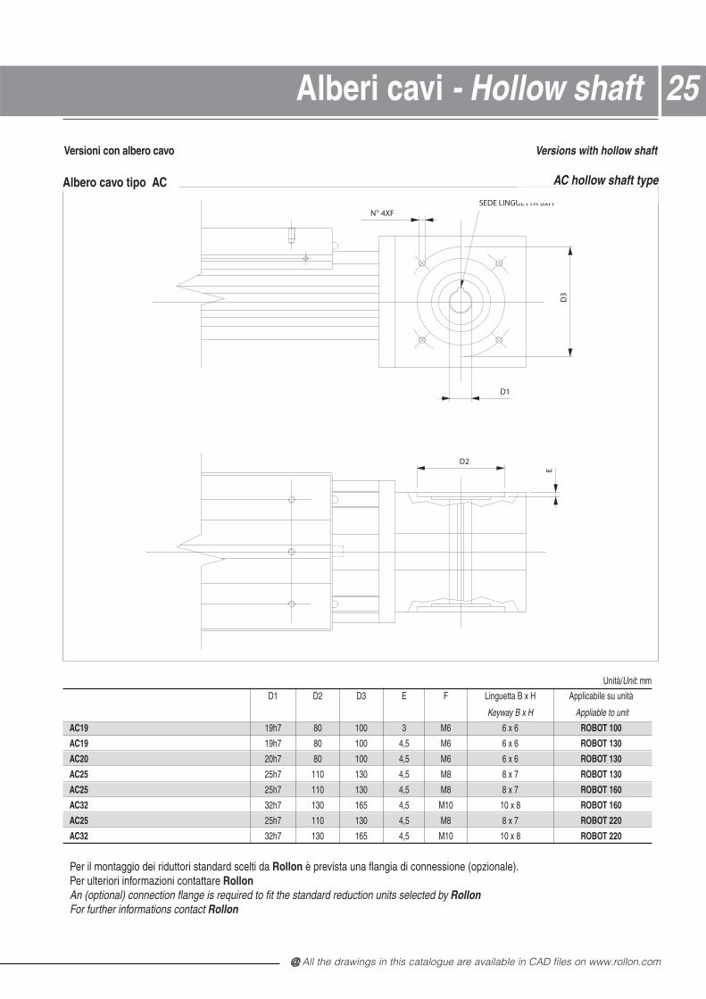
25Alberi cavi - Hollow shaft
Versioni con albero cavo Versions with hollow shaft
Unità/Unit: mm
D1 D2 D3 E F Linguetta B x H Applicabile su unità
Keyway B x H Appliable to unit
AC19 19h7 80 100 3 M6 6 x 6 ROBOT 100
AC19 19h7 80 100 4,5 M6 6 x 6 ROBOT 130
AC20 20h7 80 100 4,5 M6 6 x 6 ROBOT 130
AC25 25h7 110 130 4,5 M8 8 x 7 ROBOT 130
AC25 25h7 110 130 4,5 M8 8 x 7 ROBOT 160
AC32 32h7 130 165 4,5 M10 10 x 8 ROBOT 160
AC25 25h7 110 130 4,5 M8 8 x 7 ROBOT 220
AC32 32h7 130 165 4,5 M10 10 x 8 ROBOT 220
D3
N° 4XFSEDE LINGUETTA BxH
D2
E
D1
Albero cavo tipo AC AC hollow shaft type
Per il montaggio dei riduttori standard scelti da Rollon è prevista una flangia di connessione (opzionale).Per ulteriori informazioni contattare RollonAn (optional) connection flange is required to fit the standard reduction units selected by RollonFor further informations contact Rollon

@ Nota: tutti i disegni riprodotti nel presente stampato sono disponibili sul sito www.rollon.com in formato CAD
D3 D4 G H2 KROBOT 100 L-I - M4 - 3,4 8ROBOT 130 C - M3 - 4 6ROBOT 130 L-I 8 M6 3,3 8,3 13ROBOT 160 C - M6 - 5,8 13ROBOT 160 I 8 M6 3,3 8,3 13ROBOT 160 L 11 M8 2,8 10,8 17ROBOT 220 L-I 11 M8 2,8 10,8 17
Le unità lineari Rollon serie ROBOT possono essere montate in qualsiasi posizione grazie ai loro sistemi di traslazione checonsentono all’unità di sopportare carichi in qualsiasi direzione.
Per il fissaggio delle unità si consiglia di usare le apposite caveesterne del profilo di alluminio come nei disegni sotto riportati.
The linear motion systems used for the Rollon series ROBOT linear units enables them to support loads in any direction. Theycan therefore be installed in any position.
To instal the units, we recommend the use of the dedicated slotsin the extruded bodies as shown below.
A
Fissaggio con staffe Fixing by brackets
C
LI I
L
C
Fissaggio con dadi a T
Unità/Unit: mm
ROBOT 100 ROBOT 130 ROBOT 160 ROBOT 220A 112 144 180 240
Attenzione: non fissare le unità lineari tramite le testate alle estremità del profilo.Warning: do not fix the linear units through the heads at profile ends.
Staffa di fissaggio Blocchetto in alluminio anodizzato per il fissaggiodelle unità lineari tramite le cave laterali del profilo.
Fixing bracket Anodised aluminium block for fixing the linear units through the side slots of the body.
A
D1
F
H1
B
D2
C
E
L
L1
MONTAGGIO
K
D4
H2
D3
G
Dadi a T Dadi in acciaio da utilizzare nelle cave del profilo.T-nuts Steel nuts to be used in the slots of the body.L = Laterali / SideC = Centrali / CentralI = Inferiori / Lower
Dimensioni / Dimensions Unità/Unit: mm
A B C E F D1 D2 H1 L L1ROBOT 100 20 6 16 10 5,5 9,5 5,3 14 35 17,5ROBOT 130 20 7 16 12,7 7 10,5 6,5 18,7 50 25ROBOT 160 36,5 10 31 18,5 10,5 16,5 10,5 28,5 100 50ROBOT 220 36,5 10 31 18,5 10,5 16,5 10,5 28,5 100 50
Fixing by T-nuts
Unità/Unit: mm
26 Montaggio ed accessori

@ All the drawings in this catalogue are available in CAD files on www.rollon.com
27Assembly and accessories
Porta ProximityBlocchetto in alluminio anodizzato, colore rosso, completo di dadi aT per il fissaggio nelle cave del profilo.
Pattino per ProximityProfilo in ferro a L zincato montato sul carro ed utilizzato per inter-vento del proximity.
Proximity switch holderAnodised aluminium block, red colour, equipped with T-nuts for fixing
into the body slots.
Promixity switch runnerL-shaped bracket in zinc-plated iron, mounted on the carriage and used for
the proximity switch operation.
Attenzione: Utilizzando i soffietti non è possibile montare i porta Proximity nel profilo in alluminio.Warning: If a bellow is used, it is not possible to assemble the proximity switch holders to the aluminium body.
PORTA PROXIMITY
PATTINO PER PROXIMITYPATTINO PER PROXIMITY
PORTA PROXIMITY
B4
H4
H5
B5L4 L5
ROBOT SP
PORTA PROXIMITY
PATTINO PER PROXIMITY
PATTINO PER PROXIMITY
PORTA PROXIMITY
H5
B4
ACCESSORI PER PROXIMITY
L4 L5
ROBOT CE
Pattino per proximityProximity switch holder
Pattino per proximityProximity switch holder
Pattino per proximityProximity switch holder Porta proximity
Proximity switch runner
Porta proximityProximity switch runner
Porta proximityProximity switch runner
Unità: mmROBOT CE B4 L4 L5 H5 Per proximity / For proximity100130 57 50 40 36 12160 57 50 40 32 12
Dimensioni / DimensionsROBOT SP B4 B5 L4 L5 H4 H5 Per proximity / For proximity100 10 20 25 45 12 30 8130 24 28 50 60 20 43,5 12160 24 28 50 64 20 51 12220 24 28 50 70 20 44,5 12
Porta proximityProximity switch runner
Pattino per proximityProximity switch holder

@ Nota: tutti i disegni riprodotti nel presente stampato sono disponibili sul sito www.rollon.com in formato CAD
28 Lubrificazione - Lubrication28
Unità lineari con guide a ricircolo di sfere SP
Nelle versioni SP vengono montate guide a ricircolo di sfereesente da manutenzione.
I carrelli sono dotati di gabbie di ritenuta in plastica che evitano ilcontatto acciaio - acciaio tra corpi volventi adiacenti e riduconodisallineamenti degli stessi nei circuiti. La gabbia elimina, inoltre,lo strisciamento fra le sfere con conseguente riduzione dell’usuradovuta all’attrito.
Per rendere il sistema esente da manutenzione sui frontali deicarrelli a ricircolo di sfere sono stati installati dei serbatoi di lubrifi-cante che rilasciano la giusta quantità di grasso nelle zone ove lesfere sopportano i carichi applicati. Questo sistema garantisceuna vita di funzionamento di circa 20.000 chilometri senza rilubri-ficazione. Solo in caso di elevate dinamiche del sistema e/o dielevati carichi applicati, contattare Rollon per le necessarie verifiche.
Unità lineari con guide a rotelle CE
Le unità lineari con guide a rotelle sono dotate di unsistema di lubrificazione continuativa. Quattro feltri, intri-si di grasso di adeguata viscosità con relativi serbatoi,garantiscono una durata di ca. 6000 km senza rilubrifi-cazione. Per un'eventuale lubrificazione per arrivare adurate superiori contattare Rollon.
SP linear units with ball bearing guides
In linear units type SP maintainance-free linear ball guides areused.
The ball bearing carriages of the SP versions are also fitted witha retention cage that eliminates "steel-steel" contact betweenadjacent revolving parts and prevents misalignment of these inthe circuits.
On the front plates of the linear blocks special lube-units aremounted which are continuously providing the necessary quan-tity of grease to the ball rows under load. This system guaranteesa service life of ca. 20.000 km without relubrication. If a longerservice life is required or in case of high dynamic or high loadedapplications please contact Rollon for further verification.
The lubrication reservoirs (pockets) fitted on the cages conside-rably increase re-lubrication frequency.
Linear units type CE with lancer arch bearing guides
Linear units with lancer arch bearing guides are equipped with along period lubrication system. Four grease impregnated felt scra-pers, complete with grease reservoirs, guarantee a service life ofca. 6000 km without relubrication. If relubrication is required toobtain a higher service life please contact Rollon .

@ All the drawings in this catalogue are available in CAD files on www.rollon.com
29Protezioni - ProtectionsProtezioni standard
Cinghia di protezione
Le unità lineari Rollon serie ROBOT sono dotate di una cinghia in poliuretano a protezione di tutte le parti interne del profilo dalla polvere e dacorpi estranei. La cinghia è inserita nel profilo grazie a microcuscinetti allog-giati all’interno del carro. Questo sistema consente di mantenere la cinghia,durante la traslazione del carro, nella sua sede con valori di attrito volventemolto bassi. (Per ulteriori informazioni sulla cinghia di protezione vederepagina 32 ).
Protezione delle guide a ricircolo di sfere
I carrelli delle guide a ricircolo di sfere sono dotati di protezioni su entrambi ilati e, dove necessario, è possibile montare un ulteriore raschiatore perambienti molto polverosi.
Protezioni specialiPer l’utilizzo di unità lineari in ambienti particolarmente critici esiste la possi-bilità di corredare le unità lineari serie ROBOT di un soffietto in aggiuntaalla protezione standard già esistente. Il soffietto viene fissato al carro e alleestremità dell’unità lineare tramite un nastro Velcro. Questo sistema rendepiù semplice il montaggio e lo smontaggio per eventuali sostituzioni. La lun-ghezza totale delle unità lineari (quota L) varierà: aggiungere due volte lalunghezza del pacco chiuso del soffietto.
Standard protection
Sealing strip
The Rollon series ROBOT linear units are equipped with a polyu- rethane sealing strip to protect all parts inside the body against dust andforeign matter. The sealing strip runs the length of the body and is keptin position by micro-bearings located within the carriage. This ensuresvery low frictional resistance as it passes through the carriage. Forfurther informations about the sealing strip see pag 32 .
Protection of ball bearing guides
The four ball bearing blocks have seals on both sides and, where neces-sary, an additional scraper can be fitted for very dusty conditions.
Special protectionTo use these linear units in very critical environments, they can be fittedwith a bellows in addition to the standard protection. The bellows is fixedto the carriage and the ends of the body by means of Velcro tape foreasy assembly and disassembly.
The total length (L) of the linear unit will vary:add twice the length of the closed bellows package..
Dimensioni / DimensionsUnità: mmA C D E F T PCH per / for PA= 1000
dnamed nO - atseihcir uS001 TOBORROBOT 130 174 103 95 230 135 17 119ROBOT 160 204 131,5 110 280 160 20 100ROBOT 220 275 149,5 130 380 160 25 80
PCH = Lunghezza pacco chiusoPA = Lunghezza pacco apertoT = Profondità piega
Materiale standard: Nylon spalmato poliuretano termosaldato
Materiali su richiesta: Nylon spalmato PVC, fibra di vetro, acciaio INOX
Attenzione: L’utilizzo dei soffietti non permette il montaggio dei portaproximity nel profilo di alluminio.
PCH = Closed package lengthPA = Open package lengthT = fold depth
Standard material Thermally welded nylon coated with polyurethane
Materials on demand Nylon coated with PVC, fiberglass, stainless steel
Warning: The use of bellows does not allow the assembly of the proxi-mity switch holders to the aluminium body.
D PA E PCH F A
C
L = D + E + F + 2(PCH +5) + Corsa utile / L = D + E + F + 2(PCH + 5) + Useful stroke
Carro CE /CE carriage
Carro SP /SP carriage
@ Nota: tutti i disegni riprodotti nel presente stampato sono disponibili sul sito www.rollon.com in formato CAD
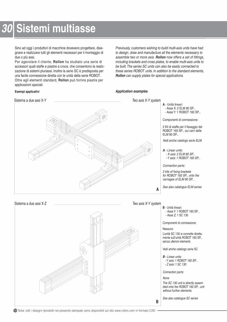
30 Sistemi multiasse30Sino ad oggi i produttori di macchine dovevano progettare, dise-gnare e realizzare tutti gli elementi necessari per il montaggio didue o più assi.Per agevolare il cliente, Rollon ha studiato una serie di accessori quali staffe e piastre a croce, che consentono la realiz-zazione di sistemi pluriassi. Inoltre la serie SC è predisposta peruna facile connessione diretta con le unità della serie ROBOT.Oltre agli elementi standard, Rollon può fornire piastre per applicazioni speciali.
Esempi applicativi
Previously, customers wishing to build multi-axis units have hadto design, draw and manufacture all the elements necessary toassemble two or more axis. Rollon now offers a set of fittings, including brackets and cross plates, to enable multi-axis units tobe built. The series SC units can also be easily connected tothese series ROBOT units. In addition to the standard elements,Rollon can supply plates for special applications.
Application examples
Sistema a due assi X-Y Two axis X-Y system
Sistema a due assi X-Z Two axis X-Y system
A - Unità lineari:- Asse X: 2 ELM 80 SP...- Asse Y: 1 ROBOT 160 SP...
Componenti di connessione:
2 Kit di staffe per il fissaggio delROBOT 160 SP... sui carri delleELM 80 SP...
Vedi anche catalogo serie ELM.
A - Linear units:- X axis: 2 ELM 80 SP...- Y axis: 1 ROBOT 160 SP...
Connection parts:
2 kits of fixing bracketsfor ROBOT 160 SP... onto thecarriages of ELM 80 SP...
See also catalogue ELM series
B - Unità lineari:- Asse Y: 1 ROBOT 160 SP...- Asse Z: 1 SC 130
Componenti di connessione:
NessunoL’unità SC 130 si connette diretta-mente sull’unità ROBOT 160 SP...senza ulteriori elementi.
Vedi anche catalogo serie SC
B - Linear units:- Y axis: 1 ROBOT 160 SP...- Z axis: 1 SC 130
Connection parts:
NoneThe SC 130 unit is directly assem-bled onto the ROBOT 160 SP... unitwithout further elements.
See also catalogue SC series
A
B
@ All the drawings in this catalogue are available in CAD files on www.rollon.com
31Multaxis systems
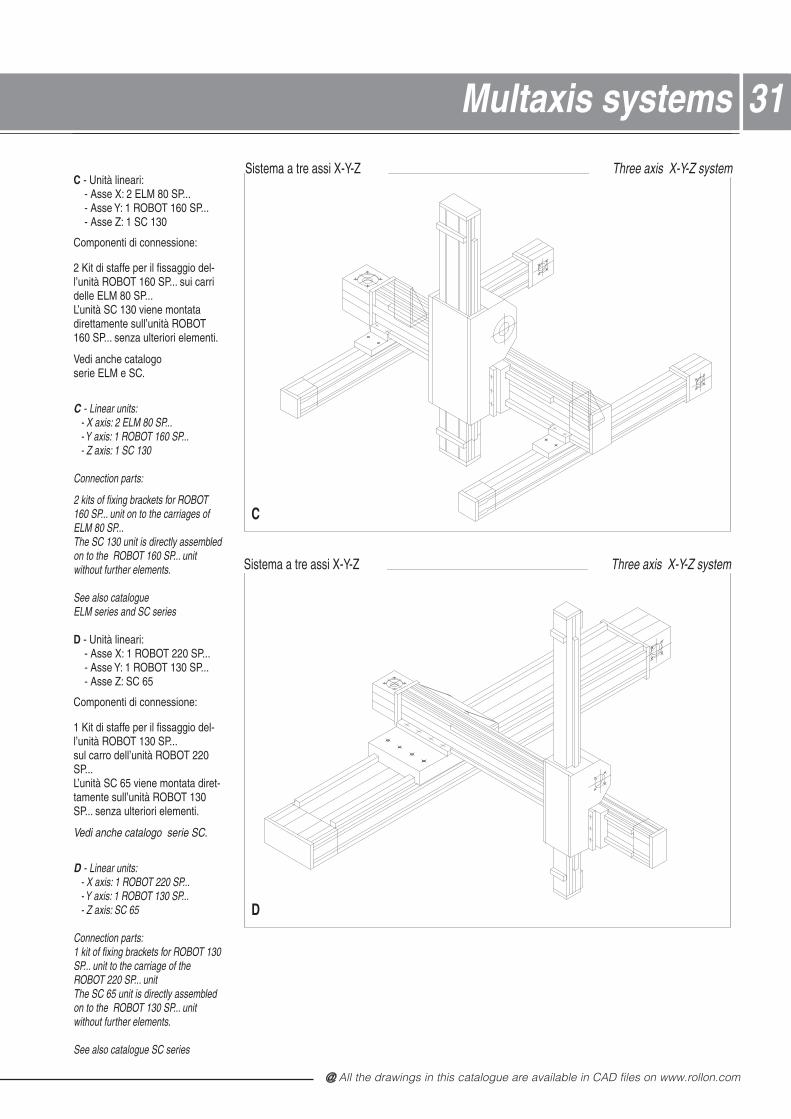
C - Unità lineari:- Asse X: 2 ELM 80 SP...- Asse Y: 1 ROBOT 160 SP...- Asse Z: 1 SC 130
Componenti di connessione:
2 Kit di staffe per il fissaggio del-l’unità ROBOT 160 SP... sui carridelle ELM 80 SP...L’unità SC 130 viene montatadirettamente sull’unità ROBOT160 SP... senza ulteriori elementi.
Vedi anche catalogoserie ELM e SC.
C - Linear units:- X axis: 2 ELM 80 SP...- Y axis: 1 ROBOT 160 SP...- Z axis: 1 SC 130
Connection parts:
2 kits of fixing brackets for ROBOT160 SP... unit on to the carriages ofELM 80 SP...The SC 130 unit is directly assembledon to the ROBOT 160 SP... unitwithout further elements.
See also catalogueELM series and SC series
D - Unità lineari:- Asse X: 1 ROBOT 220 SP...- Asse Y: 1 ROBOT 130 SP...- Asse Z: SC 65
Componenti di connessione:
1 Kit di staffe per il fissaggio del-l’unità ROBOT 130 SP...sul carro dell’unità ROBOT 220SP...L’unità SC 65 viene montata diret-tamente sull’unità ROBOT 130SP... senza ulteriori elementi.
Vedi anche catalogo serie SC.
D - Linear units:- X axis: 1 ROBOT 220 SP...- Y axis: 1 ROBOT 130 SP...- Z axis: SC 65
Connection parts:1 kit of fixing brackets for ROBOT 130SP... unit to the carriage of theROBOT 220 SP... unitThe SC 65 unit is directly assembledon to the ROBOT 130 SP... unitwithout further elements.
See also catalogue SC series
ELMAXES2 Sc.1:10
Three axis X-Y-Z systemSistema a tre assi X-Y-Z
Three axis X-Y-Z systemSistema a tre assi X-Y-Z
C
D
@ Nota: tutti i disegni riprodotti nel presente stampato sono disponibili sul sito www.rollon.com in formato CAD
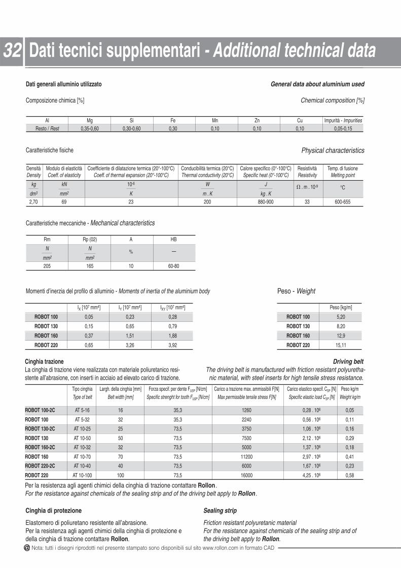
32
IX [107 mm4] IY [107 mm4] IXY [107 mm4]
ROBOT 100 0,05 0,23 0,28
ROBOT 130 0,15 0,65 0,79
ROBOT 160 0,37 1,51 1,88
ROBOT 220 0,65 3,26 3,92
Tipo cinghia Largh. della cinghia [mm] Forza specif. per dente FUSP [N/cm] Carico a trazione max. ammissibili F[N] Carico elastico specif. CSP [N] Peso kg/mType of belt Belt width [mm] Specific strenght for tooth FUSP [N/cm] Max permissible tensile stress F[N] Specific elastic load CSP [N] Weight kg/m
ROBOT 100-2C 01. 82,006213,536161-5 TA 6 0,05
ROBOT 100 01. 65,004223,532323-5 TA 6 0,11
ROBOT 130-2C 01. 60,105735,375252-01 TA 6 0,16
ROBOT 130 01. 21,200575,370505-01 TA 6 0,29
ROBOT 160-2C 01. 73,100055,372323-01 TA 6 0,18
ROBOT 160 01. 79,2002115,370707-01 TA 6 0,41
ROBOT 220-2C 01. 76,100065,370404-01 TA 6 0,23
ROBOT 220 01. 52,4000615,37001001-01 TA 6 0,58
Peso [kg/m]
ROBOT 100 5,20
ROBOT 130 8,20
ROBOT 160 12,9
ROBOT 220 15,11
Al Mg Si Fe Mn Zn Cu Impurità - ImpuritiesResto / Rest 0,35-0,60 0,30-0,60 0,30 0,10 0,10 0,10 0,05-0,15
Densità Modulo di elasticità Coefficiente di dilatazione termica (20°-100°C) Conducibilità termica (20°C) Calore specifico (0°-100°C) Resistività Temp. di fusioneDensity Coeff. of elasticity Coeff. of thermal expansion (20°-100°C) Thermal conductivity (20°C) Specific heat (0°-100°C) Resistivity Melting point
kg kN 10-6 JW . m . 10-9 °Cdm3 mm2 K. gkK. mK
556-00633009-088002329607,2
Rm Rp (02) A HB
N N% —
mm2 mm2
205 165 10 60-80
Dati generali alluminio utilizzato
Composizione chimica [%]
General data about aluminium used
Chemical composition [%]
Caratteristiche fisiche Physical characteristics
Caratteristiche meccaniche - Mechanical characteristics
Momenti d’inerzia del profilo di alluminio - Moments of inertia of the aluminium body
Cinghia trazioneLa cinghia di trazione viene realizzata con materiale poliuretanico resi-stente all’abrasione, con inserti in acciaio ad elevato carico di trazione.
Driving beltThe driving belt is manufactured with friction resistant polyuretha-
nic material, with steel inserts for high tensile stress resistance.
Per la resistenza agli agenti chimici della cinghia di trazione contattare Rollon .For the resistance against chemicals of the sealing strip and of the driving belt apply to Rollon .
Peso - Weight
Cinghia di protezione
Elastomero di poliuretano resistente all’abrasione.Per la resistenza agli agenti chimici della cinghia di protezione edella cinghia di trazione contattare Rollon.
Sealing strip
Friction resistant polyuretanic material For the resistance against chemicals of the sealing strip and ofthe driving belt apply to Rollon.
32 Dati tecnici supplementari - Additional technical data
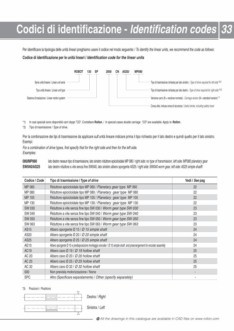
@ All the drawings in this catalogue are available in CAD files on www.rollon.com
33
Codice / Code Tipo di trasmissione / Type of drive Vedi / See pag
MP 060 Riduttore epicicloidale tipo MP 060 / Planetary gear type 22060 PMMP 080 Riduttore epicicloidale tipo MP 080 / Planetary gear type 22080 PMMP 105 Riduttore epicicloidale tipo MP 105 / Planetary gear type 22501 PMMP 130 Riduttore epicicloidale tipo MP 130 / Planetary gear type 22031 PMSW 030 Riduttore a vite senza fine tipo SW 030 / Worm gear type SW 030 23SW 040 Riduttore a vite senza fine tipo SW 040 / Worm gear type SW 040 23SW 050 Riduttore a vite senza fine tipo SW 050 / Worm gear type SW 050 23SW 063 Riduttore a vite senza fine tipo SW 063 / Worm gear type SW 063 23AS15 Albero sporgente Ø 15 / Ø 15 simple shaft 24AS20 Albero sporgente Ø 20 / Ø 20 simple shaft 24AS25 Albero sporgente Ø 25 / Ø 25 simple shaft 24AE10 Albero sporgente Ø 10 e predisposizione montaggio encoder / Ø 10 simple shaft and prearrangement for encoder assembly 24AC19 Albero cavo Ø 19 / Ø 19 hollow shaft 25AC 20 Albero cavo Ø 20 / Ø 20 hollow shaft 25AC 25 Albero cavo Ø 25 / Ø 25 hollow shaft 25AC 32 Albero cavo Ø 32 / Ø 32 hollow shaft 25
-enoN / enoizazzirotom atsiverp noN000SPC Altro (Specificare separatamente) / -)yletarapes yficeps( rehtO
Per identificare la tipologia delle unità lineari preghiamo usare il codice nel modo seguente: / To identify the linear units, we recommend the code as follows:
Codice di identificazione per le unità lineari / Identification code for the linear units
ROBOT 130 SP 2000 CN AS20/ MP080
Serie unità lineare / Linear unit serie Tipo di trasmissione richiesta per lato sinistro / Type of drive required for left side *2,3
Tipo unità lineare / Linear unit type Tipo di trasmissione richiesta per lato destro / Type of drive required for right side *2,3
Sistema di traslazione / Linear motion system Versione carro (N = versione normale) / Carriage version (N = standard version) *1
Corsa utile, inclusa corsa di sicurezza / Useful stroke, including safety travel
*1) In casi speciali sono disponibili carri doppi ”CD”. Contattare Rollon. / In special cases double carriage ”CD” are available. Apply to Rollon .*2) Tipo di trasmissione / Type of drive.
Per la combinazione dei tipi di trasmissione da applicare sull’unità lineare indicare prima il tipo richiesto per il lato destro e quindi quello per il lato sinistro.Esempi:For a combination of drive types, first specify that for the right side and then for the left side.Examples:
000/MP080 lato destro nessun tipo di trasmissione, lato sinistro riduttore epicicloidale MP 080 / right side: no type of transmission, left side: MP080 planetary gearSW040/AS25 lato destro riduttore a vite senza fine SW040, lato sinistro albero sporgente AS25 / right side: SW040 worm gear, left side: AS25 simple shaft
*3) Posizioni / Positions
Destra / Right
Sinistra / Left
33Codici di identificazione - Identification codes
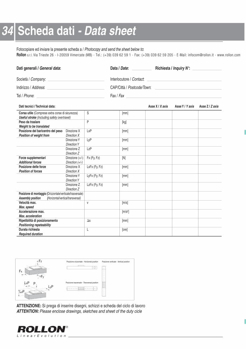
@ Nota: tutti i disegni riprodotti nel presente stampato sono disponibili sul sito www.rollon.com in formato CAD
34Fotocopiare ed inviare la presente scheda a / Photocopy and send the sheet below to:Rollon s.r.l. Via Trieste 26 - I-20059 Vimercate (MB) - Tel.: (+39) 039 62 59 1 - Fax: (+39) 039 62 59 205 - E-Mail: [email protected] - www.rollon.com
Dati generali / General data / ataD: Date: Richiesta / Inquiry N°:
Società / Company / erotucolretnI: Contact:
Indirizzo / Address / àttiC/PAC: Postcode/Town:
Tel / Phone / xaF: Fax
/ X essA:atad lacinhceT / icincet itaD X axis Asse Y / Y axis Asse Z / Z axis
Corsa utile (Comprese extra corse di sicurezza) S [mm]Useful stroke (Including safety overtravel)Peso da traslare P [kg]Weight to be translatedPosizione del baricentro del peso Direzione X LxP [mm]Position of weight from Direction X
Direzione Y LyP [mm]Direction YDirezione Z LzP [mm]Direction Z
Forze supplementari Direzione (+/-) Fx (Fy, Fz) [N]Additional forces Direction (+/-)Posizione delle forze Direzione X LxFx (Fy, Fz) [mm]Position of forces Direction X
Direzione Y LyFx (Fy, Fz) [mm]Direction YDirezione Z LzFx (Fy, Fz) [mm]Direction Z
Posizione di montaggio (Orizzontale/verticale/trasversale)Assembly position (Horizontal/vertical/transversal)Velocità max. ]s/m[vMax. speedAccelerazione max. [m/s2]Max. accelerationRipetibilità di posizionamento s [mm]Positioning repeteabilityDurata richiesta ]ero[LRequired duration
ATTENZIONE: Si prega di inserire disegni, schizzi e scheda del ciclo di lavoroATTENTION: Please enclose drawings, sketches and sheet of the duty cicle
Scheda dati - Data sheet34
LxP
LzPLyP
P
Fz
Fy
Fx
Posizione orizzontale - Horizontal position Posizione verticale - Vertical position
Posizione trasversale - Transversal position
RL_ROBOT_IT-UK_01/12 INTERNATIONAL
Gli indirizzi aggiornati dei nostri partner commerciali sitrovano all‘indirizzo www.rollon.comAll addresses of our global sales partners can alsobe found on the internet at www.rollon.com
Salvo errori e variazioni. Testi e illustrazioni possono essere utilizzati solo previa autorizzazione da parte nostra. - Change s and errors excepted. The text and images may be used only with our permission.
Italy
ROLLON S.r.l.
Via Trieste 26
Fax: (+39) 039 62 59 205
E-Mail: [email protected]
www.rollon.it
I-20871 Vimercate (MB)
Phone: (+39) 039 62 59 1
Germ
any
ROLLON GmbH
Bonner Straße 317-319
D-40589 Düsseldorf
Phone: +49 (0) 211 95 747 0
Fax: +49 (0) 211 95 747 100
E-Mail: [email protected]
www.rollon.de
Fran
ce
ROLLON S.A.R.L.
Les Jardins d‘Eole, 2 allée des Séquoias
F-69760 Limonest
Phone: (+33) (0)4 74 71 93 30
Fax: (+33) (0)4 74 71 95 31
E-Mail: [email protected]
www.rollon.fr
USA
ROLLON Corporation
101 Bilby Road. Suite B
Hackettstown, NJ 07840
Phone: +1 (973) 300-5492
Fax: +1 (908) 852-2714
E-Mail: [email protected]
www.rolloncorp.com
Ringbaan Zuid 8
NL-6905 DB Zevenaar
Phone: (+31) 316 581 999
Fax: (+31) 316 341 236
E-Mail: [email protected]
www.rollon.nlNeth
erla
nds
ROLLON B.V.