activity booklet of fischertechnik pneumatic3
DESCRIPTION
Activity Booklet of fischertechnik Profi Pneumatic3TRANSCRIPT


19
P R O F I P N E U M A T I C 3 A C T I V I T Y B O O K L E T
ContentsFundamentals of Pneumatics P. 20
Advantages of Pneumatics P. 20
A Brief History P. 21
Pneumatic Systems and Components P. 22
Generating Compressed Air P. 22Distributing Compressed Air P. 23Conditioning and Filtering Compressed Air P. 23Generating and Controlling Motion P. 23
Pneumatic Cylinders P. 23Valves P. 26
Functional Pneumatic Models P. 28
Scissors-type Lift P. 28Balloon Pump P. 30Double Sliding Doors P. 31Catapult P. 32
Pneumatic Play Models P. 34
If something doesn't work right P. 34
More About Pneumatics P. 35
2 Profi Pneum-III_GB.indd 192 Profi Pneum-III_GB.indd 19 13.06.2012 18:48:4913.06.2012 18:48:49

20
P R O F I P N E U M A T I C 3 A C T I V I T Y B O O K L E T
Fundamentals
of Pneumatics
■ Compressed air is so common, it is hard to imagine getting along without it. More than likely you will encounter it daily, directly or indirectly. This can start with your breakfast eggs, which may have been packed with the aid of a pneumatic vacuum gripper. Or at the dentist's when he drills out a cavity with a pneumatically driven drill. You can see pneumatics on construction sites, when a jackhammer is used to break up pavement, in the brake system on your car or in many other situations.
The word pneumatics comes from the Greek word “pneuma” meaning air. Pneumatics focuses on generating motion and accomplishing mechanical work with air. Almost anything can be driven with air. It can be used as an alternative for muscular force or any other type of energy such as electricity, water, hydraulic oil or wind power.
■ The advantages of pneumatics are that ...compressed air can be stored• compressed air can be transported over great distances with pipes • and hoses or in appropriate reservoirscompressed air is clean and does not cause any contamination• movements can be performed quickly with compressed air• with pneumatic cylinders many motions can be realized without • complicated mechanical systemscompressed air is not explosive•
Your Pneumatic 3 Construction Set explains these advantages and further interesting information. Moreover we want to show you how pneumatic components work. For this purpose we explain the individual components step by step and show how they work. Moreover the construction set contains numerous examples of models showing how pneumatics can be used.
Advantages
of Pneumatics
2 Profi Pneum-III_GB.indd 202 Profi Pneum-III_GB.indd 20 13.06.2012 18:48:4913.06.2012 18:48:49

21
P R O F I P N E U M A T I C 3 A C T I V I T Y B O O K L E T
A Brief History■ Over 2000 years ago the Greek engineer and inventor Ktesibios built the first machines powered by compressed air, for example, a catapult which used compressed air to hurl shot and spears. Heron of Alexandria built one of the best known compressed air systems, which used the altar fi re to generate compressed air to open the huge temple doors, as if by magic.
The heat from the altar fi re heated the air in a pressure reservoir half fi lled with water. When the air was heated, it expanded, increasing the air pressure. The expanding air required more space, thus pressing the water out of the pressure reservoir into a water tank. As the weight increased the water tank moved downward, opening the doors.
■ Since the beginning of the 20th century pneumatic systems have been used to drive and control machines in industrial applications. In the fi eld of construction and agricultural machines pneumatic systems are used to drive hammers and drills. In conveying technology, pneumatic systems use vacuum and
pressure for applications such as sucking grain into fl our mills or conveying fl our. Even in the fi eld of music, pneumatics are used for applications such as organs.
In a pianola, a player piano, the keys are controlled pneumatically. You can observe pneumatic systems in action in the automotive industry, the textile and foodstuffs
industry, electrical engineering, and even in space technology and many other areas encountered every day.
Lift
Chain
Gearbox
Water reservoirPressure reservoir
Altar
2 Profi Pneum-III_GB.indd 212 Profi Pneum-III_GB.indd 21 13.06.2012 18:48:4913.06.2012 18:48:49

22
P R O F I P N E U M A T I C 3 A C T I V I T Y B O O K L E T
■ Any pneumatic system consists of fi ve subsystems for Generating compressed air• Distributing compressed air• Conditioning and fi ltering compressed air• Generating motion with pneumatic cylinders• Control of the motion with valves•
■ Compressed air can be generated with a compressor, blower or air pump and stored in compressed air bottles or other pressure reservoirs.
Diaphragm Pump as Compressor
The diaphragm pump included in the construction set supplies the compressed air required for you to control the individual models. In industry, this is called the compressed air source.
How It Works A diaphragm pump consists of two chambers separated by a diaphragm (membrane). In one chamber the resilient diaphragm is moved up and down by a piston or cam. During the downward stroke the diaphragm is pulled back and air is pulled into the second chamber through the inlet valve. When the piston moves up, the diaphragm presses the air out of the pump head through the outlet valve.
Note: The pressure generated by the fi schertechnik compressor is approx. 0.7 to 0.8 bars. The diaphragm pump is maintenance-free.It is important to use a 9V alkaline battery to supply power to the compressor. Even better, of course, is the fi schertechnik Accu Set, which can supply signifi cantly more power than the 9V battery, lasts much longer and can be recharged again and again. The maximum charging time is two hours.
Generating
Compressed Air
Hose connection
Connection for green and red leadsC
H
Piston
Cylinder
Diaphragm
Inlet/outlet valve
Cover
Crank drive
Pneumatic
Systems and
Components
2 Profi Pneum-III_GB.indd 222 Profi Pneum-III_GB.indd 22 13.06.2012 18:48:5013.06.2012 18:48:50

23
P R O F I P N E U M A T I C 3 A C T I V I T Y B O O K L E T
■ The compressed air can be transported to the location required with the blue hoses. You can lay the air lines from the compressor to the valves and cylinders.
■ To ensure that the pneumatic components operate correctly in industrial applications, it is important to condition the compressed air properly. For this purpose it is necessary to fi lter, cool, dehumidify and add oil to the air. However with the models in your Pneumatic 3 Construction Set this is not required.
Pneumatic Cylinders
■ We use pneumatic cylinders to generate motion with air. As a matter of principle we differentiate between "single acting" and "double acting" cylinders.Your Pneumatic 3 Construction Set contains two different sizes of pneumatic cylinders with the same "double acting" function.
The blue piston rod is movable and seals the cylinder. If you blow air into the cylinder through one of the two hose connections, the piston rod moves. If air is blown into the opposite side, the piston moves
Distributing
Compressed Air
Conditioning
Compressed Air
Generating and
Controlling Motion
60 Cylinder
Hose connections
Piston rod
Piston with sealsston wit
45 Cylinder
Hose connections
Piston rod
Piston with sealsston wit
2 Profi Pneum-III_GB.indd 232 Profi Pneum-III_GB.indd 23 13.06.2012 18:48:5113.06.2012 18:48:51

24
P R O F I P N E U M A T I C 3 A C T I V I T Y B O O K L E T
back in the other direction. The piston therefore has an active function in both directions of motion. The connection which causes the piston rod to extend is designated connection A, and the connection for retracting the piston rod is called connection B. Since the piston rod in the cylinder can be extended as well as retracted by the air, we call the cylinder a "double acting" cylinder. You can perform an experiment to examine this in practical application.
Experiment:Fasten a piece of the blue hose to connection A on a cylinder and connect it to the hose connection on the compressor, which is already connected to the battery holder. When you switch on the compressor, the piston rod extends. Since the cylinder is double acting, the piston moves back when you connect the hose to connection B and blow in compressed air with the compressor.
Connect hose,
switch on compressor
A
B
Connect hose, switch on compressor
A
B
As already mentioned, however, there are also "single acting" cylinders. With such cylinders the piston rod moves in one direction only. A spring is frequently used to move it back in the other direction.
You can perform another experiment to show that air can be compressed (pressed together).
2 Profi Pneum-III_GB.indd 242 Profi Pneum-III_GB.indd 24 13.06.2012 18:48:5113.06.2012 18:48:51

25
P R O F I P N E U M A T I C 3 A C T I V I T Y B O O K L E T
Experiment:Now extend the piston in the cylinder again by connecting your blue hose leading to the compressor to connection A and blowing in compressed air. After the piston has extended, change to hose connection B and plug hose connection A by holding it closed with your fi nger.
Connect hose,
switch on compressor
A
B
Connect hose, switch on compressor
A
B
Hold shut
AA
?
Observation:The piston can only be pressed in a short distance. Do you know why?
Explanation:Since you held air connection A closed with your fi nger, it was not possible for the air to escape. However air can be pressed together. For this reason the piston rod was pushed back slightly. The more the air is pressed together, the greater the air pressure in the cylinder. The pressure can be measured with a pressure gage or it can also calculated. The unit for pressure is "bars" or "Pascals". The pressure can also be calculated. The equation for calculating the pressure is:
Pressure = force/area or p = F/A
This equation shows that the pressure depends on the amount of force exerted on the round surface in the cylinder.
As you recognized in your experiment, it is rather cumbersome to reconnect the hoses repeatedly. This work can also be accomplished by valves, as explained in detail in the next chapter.
Pressure gage
2 Profi Pneum-III_GB.indd 252 Profi Pneum-III_GB.indd 25 13.06.2012 18:48:5213.06.2012 18:48:52

26
P R O F I P N E U M A T I C 3 A C T I V I T Y B O O K L E T
Valves
■ In pneumatics, the purpose of a valve is to control the fl ow of air to the pneumatic cylinder so that the cylinder is extended or retracted. A valve can be actuated mechanically, electrically, pneumatically or manually.
Your Pneumatic 3 Construction Set contains manual valves. Each of these valves has four connections:
The middle connection P is for the compressed air coming from the compressor. The left or right fi tting (A or B) guides the compressed air to connection A or connection B on the cylinder. The connection marked R on the bottom of the valve serves to release the air or "relieve" the air pressure. This allows the air returning from the cylinder to escape. Perform the following experiment to see how the valve works.
Experiment:Connect the compressor, which is already connected to the battery holder, to one of your valves. For this purpose take a piece of the blue hose and fasten it to the hose connection on the compressor and to connection P on the valve. Leave the other connections free. Set the blue switch on the manual valve to the center position and switch on the compressor.
Observation:Nothing happens at all.
Explanation:When the switch on the manual valve is set to the center position, the connections are closed and the air cannot fl ow in any direction.
BPA
R
A B
2 Profi Pneum-III_GB.indd 262 Profi Pneum-III_GB.indd 26 13.06.2012 18:48:5213.06.2012 18:48:52

27
P R O F I P N E U M A T I C 3 A C T I V I T Y B O O K L E T
Then turn the switch on the valve to the right (clockwise) and switch on the compressor again. While doing this tap against the free fi ttings A and B repeatedly with your fi nger. Do the same after turning the valve switch to the left (counterclockwise).
Observation:The air always fl ows through connection A when you turn the blue switch on the valve to the right (clockwise) and through connection B when you turn it to the left (counterclockwise).
Explanation:This illustration helps you to understand how the air fl ows through the valve when you turn the switch in the various directions. Here the light colored line is compressed air fl owing through the valve. The dark lines show you how the air fl ows as it returns from the cylinder.
R
P
AB
R
P
ABR
P
AB
Left Center Right
The valve has four connections and three switch positions (center - left - right). For this reason the valve is called a 4/3-way valve in pneumatic jargon.
2 Profi Pneum-III_GB.indd 272 Profi Pneum-III_GB.indd 27 13.06.2012 18:48:5313.06.2012 18:48:53

28
P R O F I P N E U M A T I C 3 A C T I V I T Y B O O K L E T
■ Now let's take a closer look at what we have just learned with our own models to see exactly how pneumatics are used in reality.For this purpose assemble the four models one after another and perform one or two experiments with each to get a better understanding of how everything works.
■ Lifts are frequently used to hoist heavy loads. They are used particularly for loading workpieces into machines. Such a lift consists of a base frame, on which the load is placed. Two levers of equal length are attached to this frame. These levers move along the center point of a shaft mounted on the base frame.
To properly understand the design of a scissors-type lift, fi rst build the model as described in the assembly instructions.
Scissors-type lift – Task 1:After connecting the compressor and routing the hoses as described in the assembly
instructions, turn the blue switch on the valve to the right (clockwise). What happens? The lift moves up. But why?
The piston in the cylinder extends because you connected the hoses on your model so that the compressed air fl ows from connection A on the valve to connection A on the cylinder. This extension motion shifts the center axis of the lift to the right, pushing the levers and therefore the platform up.You can move the lift back down by turning the valve to the left (counterclockwise) and retracting the piston into the cylinder.
Scissors-type lift – Task 2:But what happens when the lift has to hoist a heavy load, such as a cup or mobile phone? Can you still move the lift up? Try to fi nd out how much weight the lift will still just hoist. Enter this value in the table below.
Scissors-type Lift
Functional
Pneumatic
Models
2 Profi Pneum-III_GB.indd 282 Profi Pneum-III_GB.indd 28 13.06.2012 18:48:5313.06.2012 18:48:53
29
P R O F I P N E U M A T I C 3 A C T I V I T Y B O O K L E T
Object Weight in grams Lift moves up - Yes/No
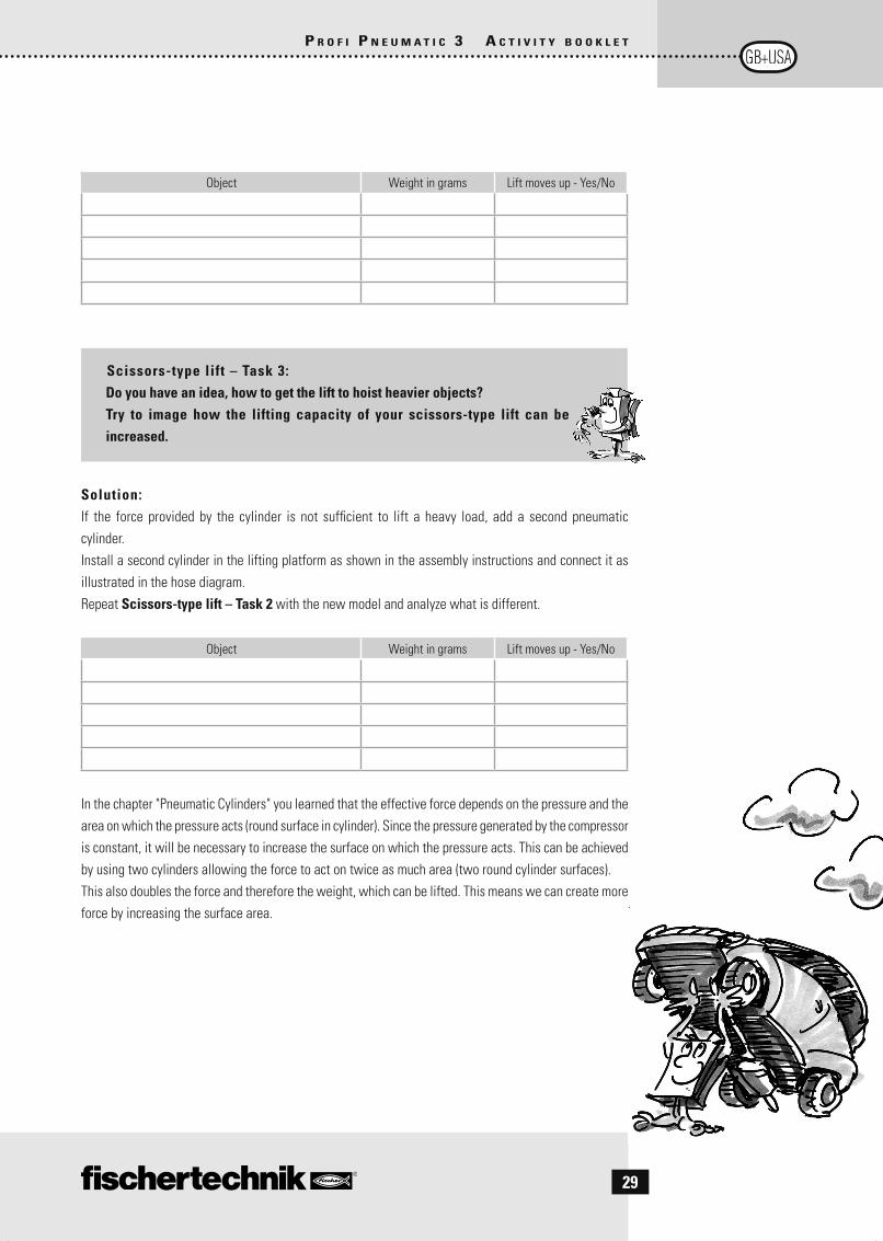
Scissors-type lift – Task 3:Do you have an idea, how to get the lift to hoist heavier objects?Try to image how the lifting capacity of your scissors-type lift can be increased.
Solution:If the force provided by the cylinder is not suffi cient to lift a heavy load, add a second pneumatic cylinder.Install a second cylinder in the lifting platform as shown in the assembly instructions and connect it as illustrated in the hose diagram. Repeat Scissors-type lift – Task 2 with the new model and analyze what is different.
Object Weight in grams Lift moves up - Yes/No
In the chapter "Pneumatic Cylinders" you learned that the effective force depends on the pressure and the area on which the pressure acts (round surface in cylinder). Since the pressure generated by the compressor is constant, it will be necessary to increase the surface on which the pressure acts. This can be achieved by using two cylinders allowing the force to act on twice as much area (two round cylinder surfaces).This also doubles the force and therefore the weight, which can be lifted. This means we can create more force by increasing the surface area.
2 Profi Pneum-III_GB.indd 292 Profi Pneum-III_GB.indd 29 13.06.2012 18:48:5313.06.2012 18:48:53

30
P R O F I P N E U M A T I C 3 A C T I V I T Y B O O K L E T
Balloon Pump ■ You have certainly blown up balloons many times before. And you know how you mouth starts hurting after a while and you get out of breath, don't you? Well that's enough of that! With our next model, a balloon pump, that won't happen any more, because with this pump you can blow up balloons pneumatically. To see how this works, build the model with the aid of the assembly instructions.
After completing this model, turn the valve switch to the right (clockwise) to allow air to fl ow through connection A into the balloon. The air escapes from the balloon through connection R, when the valve switch is turned to the left (counterclockwise).
Balloon – Task 1:How much time do you need to blow up the balloon completely with the compressor? Use a stop watch to measure how long it takes.
Balloon – Task 2:Now calculate the volume of your blown-up balloon. For this purpose seal the balloon (tie a knot in the end). Take a bucket and fi ll it full of water, right up to the edge. Then place a container below the bucket. Push the balloon down into the water, so it is completely submerged. Some water will overfl ow into the container below the bucket. Fill the water, which has overfl owed into a measuring cup with increments in liters. Now you know the volume of the balloon in liters.
By the way, you can also use this method to measure the volume of air in your lungs by blowing it up as far as possible with one breath, instead of with the pump.
Balloon – Task 3:Does air have weight? Perform the following experiment to fi nd out. For this you need a set of precise scales (such as a letter balance) and the balloon included with your construction set. In the fi rst step weigh the balloon and jot down the weight. Then in the second step blow up
the balloon completely with the aid of your model. Then measure and write down the weight of the balloon after blowing up. What is the difference?
Observation:When blown up the balloon is slightly heavier than when empty.
2 Profi Pneum-III_GB.indd 302 Profi Pneum-III_GB.indd 30 13.06.2012 18:48:5313.06.2012 18:48:53

31
P R O F I P N E U M A T I C 3 A C T I V I T Y B O O K L E T
Explanation:The balloon contains air when it is blown up. Air has weight and exerts pressure. Galileo Galilei was the fi rst to discover this in the 16th century. One liter of air weighs approximately 1.3 grams. But the weight of air is not always the same. Hot air is lighter than cold air, because the molecules are farther apart. 1.3 grams doesn't sound like much, but a dense jacket of air surrounds the earth with a thickness of approximately 100 kilometers. This means that air presses down on your body with a weight of nearly 5,500 kilograms. We do not feel this weight, because our body exerts a counter pressure. But when you take off or land in an airplane, for example, you can feel this pressure in your ears.
■ You probably walk though sliding doors such as those in department stores or public trains or buses frequently. Such doors can be opened manually as well as electrically, hydraulically or pneumatically. Buses or lightrails frequently have sliding doors, which are opened and closed by compressed air. As early as 1927 the sliding doors on the streetcars in Berlin were opened pneumatically. You have probably heard the hissing noise from the compressed air escaping when the doors open on a lightrail.
Double sliding doors – Task 1:Now build a pneumatically controlled double sliding door. Try to build it
so that both doors are opened and closed by one valve. Do you have any idea how to control two cylinders with only one valve?
The solution is also given in your assembly instructions. To solve this problem connect the two cylinders in series as described in the assembly instructions. This means that the same compressed air fl ows through both cylinders. When you set the valve on the model you have built to connection A, both cylinders are retracted by this air fl ow, causing the doors to open. You can extend the pistons to close the doors again by turning the valve back to the left (counterclockwise).
Double sliding doors – Task 2:As you know such systems are not controlled by hand in reality. Do you have any idea how such systems are controlled automatically?
Solution:In reality manual valves are not used to open doors. Instead, this is accomplished by valves opened and closed by an electrical pulse. The valves receive the pulse from a programmable logic controller, abbreviated
Double Sliding Door
2 Profi Pneum-III_GB.indd 312 Profi Pneum-III_GB.indd 31 13.06.2012 18:48:5413.06.2012 18:48:54

32
P R O F I P N E U M A T I C 3 A C T I V I T Y B O O K L E T
PLC. The programmer determines the sequence in which the valves are to be actuated, saves the program and the system functions automatically.
The Chapter "More About Pneumatics" describes how you can automate your models with fi schertechnik.
■ At the beginning of the activity booklet, you already learned that the Greek Ktesibios built the fi rst catapult a long time ago. If he was able to build such a machine, you certainly can too!
Catapult – Task 1:Build a pneumatically controlled catapult using a cylinder without instructions. Do
you have any idea how to do this? If not, you can read our recommendations in the assembly instructions.
Catapult – Task 2:Perform another experiment to determine the throwing capacity of a simple catapult. For this you need a measuring tape / yardstick and a 15 black block. Place the block in the "basket" provided for this purpose on the catapult arm. Then actuate the manual valve and measure how far the block was thrown. Remember to defi ne a starting point for measuring the distance. (e.g. end of the model on the basket side). Enter your value in the table.
Type of model Throwing distance in cm
Simple model
Catapult – Task 3:Your catapult should work well. But now we want to try to catapult the block further. Can you think of any way to do this?
Catapult
15 Block
2 Profi Pneum-III_GB.indd 322 Profi Pneum-III_GB.indd 32 13.06.2012 18:48:5413.06.2012 18:48:54

33
P R O F I P N E U M A T I C 3 A C T I V I T Y B O O K L E T
Solution 1:With the fi rst model the compressor was connected directly to the middle connection marked P on the manual valve without a reservoir for storing the air. On our next model we now will add two air reservoirs. For the next model this means that the compressed air from the compressor flows to the other cylinders instead of directly to the manual valve. These cylinders are therefore fi lled with compressed air, which they store.
Now add two cylinders to serve as air reservoirs in your simple model. If you do not know exactly how to add the air reservoirs to your model, check in the assembly instructions.
After converting your model, place the block in the catapult arm and again actuate the manual valve to catapult the block. Now again note how far the block was thrown.
Type of model Throwing distance in cm
Model with air reservoir
What do you observe? Which one provides better results? Do you know why?
Observation:The block is thrown further by the model with air reservoir.
Explanation:The compressor can only provide a certain volume of air at any given pressure. This means that at a constant pressure of 0.7 to 0.8 bars, it delivers an air volume of approx. two liters per minute. Use of a reservoir makes a greater volume of air available more quickly. This volume is available immediately, and does not fi rst have to be produced by the compressor. This makes the catapult arm move faster by increasing the acceleration force acting on the block and thus throwing it farther.
Solution 2:You may be familiar with Archimedes boast "Give me a lever long enough and strong enough and I can move the earth." This so-called law of leverage is a technical concept. For you and your model this means that a longer lever exerts more force.
Therefore increase the length of the catapult arm, the lever, on your model and measure how far the block is thrown. You will see that you can confi rm the law of leverage with your model.
2 Profi Pneum-III_GB.indd 332 Profi Pneum-III_GB.indd 33 13.06.2012 18:48:5513.06.2012 18:48:55

34
P R O F I P N E U M A T I C 3 A C T I V I T Y B O O K L E T
Type of model Throwing distance in cm
Model with longer lever
We have now reached the end of our introductory chapter. As you can see, pneumatics is very effective and very interesting. In the next chapter you can use the play models from the Pneumatic 3 Construction Set.
■ In addition to the operating models, the Profi Pneumatic 3 Set includes four additional models with fascinating and amusing functions. These include realistic models of a hay bale picker, tree trunk grip, front loader and excavator. Here you can also install the compressor in your model and connect it with your pneumatic valves and cylinders. The manual valves then allow you to manually control the gripper arm on the hay bale picker or tree trunk grip. You can put together the remaining blocks as cargo and load them on a toy truck or similar.
In reality, functions like these are accomplished with the aid of hydraulics, instead of pneumatics. Hydraulic applications use oil instead of air to move the cylinders. In contrast to air, oil cannot be compressed, allowing it to transfer signifi cantly higher forces. However, for your play models in the Pneumatic 3 Construction Set the forces achievable with pneumatic actuation are fully suffi cient. Moreover it is particularly clean, quick, reliable and above all, fascinating.We hope you have a great deal of fun building and playing with the models.
■ If one of your models does not work right, please check the following table. It provides a list of possible errors and the associated causes. Moreover the table is intended to provide you with tips on how to eliminate the faults in each individual case.
Fault Possible Cause SolutionCompressor does not run
Battery missing• Battery holder not switched on• Leads not plugged in correctly•
9V block battery or Accu Set• Check leads•
No motion A number of valves are in position A or B (too much air • fl owing out through valves)
Move all valves back to the • middle position (off position) after each motion
Pneumatic
Play Models
If something
doesn't work
right
2 Profi Pneum-III_GB.indd 342 Profi Pneum-III_GB.indd 34 13.06.2012 18:48:5513.06.2012 18:48:55

35
P R O F I P N E U M A T I C 3 A C T I V I T Y B O O K L E T
Fault Possible Cause SolutionApparently the compressor is running normally, but the pneumatic cylinder to be activated moves very slowly or not at all
Manual valve leaky • Check: Move valve to middle position. Apply pressure to all three connections one after the other and hold under water. If large quantities of bubbles rise, the valve is leaky Pneumatic cylinder leaky • Check: Apply pressure to all three connections one after the other and hold under water. If large quantities of bubbles rise, the cylinder is leaky
Replace manual valve•
Replace pneumatic cylinder•
The compressor and all cylinders are okay, but one cylinder still does not extend
Hose is clogged at one point • Hose kinked • Check: Connect each hose to the compressor by itself and check whether compressed air is blown through. You can hear and feel the air
If necessary, replace clogged • hose Ensure that the hose is not • kinked
■ The fascinating subject of pneumatics is not concluded with the Profi Pneumatic 3 Set by any means. In the Chapter "Double Sliding Door" we already mentioned that in reality pneumatic models are automated. The ROBO TX ElectroPneumatic Construction Set is just what you need to fi nd out how your models can be automated electro-pneumatically or with vacuum. With this construction set, pneumatic models such as a pinball machine, compressed air motor, color sorting robot or ball obstacle course are controlled with electropneumatic valves instead of by hand. With the aid of the ROBO TX Controller and the simple ROBO Pro software the models can be programmed and controlled with your computer. This is truly state of the art!
If you have anything to do with pneumatics in the future in your everyday life during your education or later in your occupation, you are sure to remember your Pneumatic 3 Construction Set. You will fi nd that in principle "real" pneumatics works just the same as in your fi schertechnik construction set and that you are already familiar with the basics.
More About
Pneumatics
2 Profi Pneum-III_GB.indd 352 Profi Pneum-III_GB.indd 35 13.06.2012 18:48:5513.06.2012 18:48:55

36
P R O F I P N E U M A T I C 3 A C T I V I T Y B O O K L E T
2 Profi Pneum-III_GB.indd 362 Profi Pneum-III_GB.indd 36 13.06.2012 18:48:5513.06.2012 18:48:55