active implants in mri - amos onlineamos3.aapm.org/abstracts/pdf/99-28936-359478-114565.pdf ·...
TRANSCRIPT

Active Implants in MRI: Implanted Device Industry Perspective
Ross Venook, Ph.D.
Boston Scientific Neuromodulation

Disclosure
• I am an employee of Boston Scientific Neuromodulation Corporation
16JUL2015 Venook ~ AAPM ~ MRI Safety 2

Outline
• Motivation (for implant manufacturers)
• Types of devices, interactions, and hazards
• Technical example: RF interactions/hazards
• Engineering approaches and perspectives
• Summary and Review Questions
16JUL2015 Venook ~ AAPM ~ MRI Safety 3

Motivation for Safety of Implantable Devices under MRI
• Increasing patient population with IMDs – Passive: joint replacements, stents, heart valves, etc. – Active: pacemakers/defibrillators, neurostimulators,
drug pumps, etc.
• Increasing diagnostic indications for MRI – Many IMD patients have MRI on pathway to implant – IMD patients may later be indicated for MRI
• Scanning patients with IMDs is challenging – Scanning an MR Conditional patient can be complex – Risk/benefit trade-off not well characterized for most
implants and patients
More
Patients,
Living
Longer
Increasing
Value of
MRI Exams
Barriers in
Patient
Pathway to
MRI
16JUL2015 Venook ~ AAPM ~ MRI Safety 4

Types of implantable devices
• Passive (no powered electronic components)
• Active (with powered electronic components)
16JUL2015 Venook ~ AAPM ~ MRI Safety 5

Types of implantable devices • Passive (no powered electronic
components) – Orthopedic
• Hips, knees, rods, screws
– Cardiovascular • Stents, stent-grafts, valves
– Neurovascular • Aneurysm clips, aneurysm coils
– Interventional • Guide wires, catheters
• Active (with powered electronic
components)
16JUL2015 Venook ~ AAPM ~ MRI Safety 6

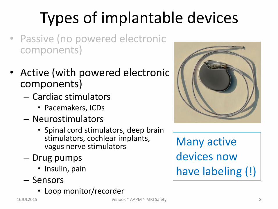
Types of implantable devices • Passive (no powered electronic
components)
• Active (with powered electronic components) – Cardiac stimulators
• Pacemakers, ICDs
– Neurostimulators • Spinal cord stimulators, deep brain
stimulators, cochlear implants, vagus nerve stimulators
– Drug pumps • Insulin, pain
– Sensors • Loop monitor/recorder
16JUL2015 Venook ~ AAPM ~ MRI Safety 7
Types of implantable devices • Passive (no powered electronic
components)
• Active (with powered electronic components) – Cardiac stimulators
• Pacemakers, ICDs
– Neurostimulators • Spinal cord stimulators, deep brain
stimulators, cochlear implants, vagus nerve stimulators
– Drug pumps • Insulin, pain
– Sensors • Loop monitor/recorder
16JUL2015 Venook ~ AAPM ~ MRI Safety 8
Many active devices now have labeling (!)

Implantable Device Labeling – Definition of MR Safe (ASTM F2503)
“MR Safe—an item that poses no known hazards in all MR environments.”
• E.g., plastic bed pan, Petri dish
– Definition of MR Conditional (ASTM F2503) “MR Conditional—an item that has been demonstrated to pose no
known hazards in a specified MR environment with specified conditions of use. Field conditions that define the specified MR environment include field strength, spatial gradient, dB/dt (time rate of change of the magnetic field), radio frequency (RF) fields, and specific absorption rate (SAR). Additional conditions, including specific configurations of the item, may be required.”
• E.g., many orthopedic implants, some active implants
– Definition of MR Unsafe (ASTM F2503) “MR Unsafe—an item that is known to pose hazards in all MR environments”
• E.g., ferromagnetic scissors 16JUL2015 Venook ~ AAPM ~ MRI Safety 9

Implantable Device Labeling – Definition of MR Safe (ASTM F2503)
“MR Safe—an item that poses no known hazards in all MR environments.”
• E.g., plastic bed pan, Petri dish
– Definition of MR Conditional (ASTM F2503) “MR Conditional—an item that has been demonstrated to pose no
known hazards in a specified MR environment with specified conditions of use. Field conditions that define the specified MR environment include field strength, spatial gradient, dB/dt (time rate of change of the magnetic field), radio frequency (RF) fields, and specific absorption rate (SAR). Additional conditions, including specific configurations of the item, may be required.”
• E.g., many orthopedic implants, a few active implants
– Definition of MR Unsafe (ASTM F2503) “MR Unsafe—an item that is known to pose hazards in all MR environments”
• E.g., ferromagnetic scissors 16JUL2015 Venook ~ AAPM ~ MRI Safety 10

AIMD/MR Interactions, by MR Field
16JUL2015 Venook ~ AAPM ~ MRI Safety 11
Source
Field
Interaction
Means Interaction Hazards
B0
Torque IPG/Lead twist to align magnetic moment with static field
Translation IPG/Lead pulled in response to static field gradient
Magnetization Residual magnetization in IPG/lead components alters behavior
Magnetic Saturation Saturation of ferrite-core inductors lowers effective inductance
Gx,y,z
Induced Current in
Leads Unintended tissue stimulation at lead tip(s)
High currents injected through header
EMI Interference with circuitry, especially telemetry coil and charging coil
Induced Eddy Currents Induced eddy currents in metal surfaces (case, ground planes) cause
resistive heating
B1 (RF) Induced RF Heating Focused RF tissue heating near device
EMI Induced voltages at IPG terminals, rectification, induced stimulation
B0 + Gx,y,z Eddy current torque Induced eddy currents have magnetic moment that torques to align with large
static field
B0 + Gx,y,z +
B1
Combined effects Combination of factors that can affect either the device or MR image quality

AIMD/MR Interactions, by Risk Level
16JUL2015 Venook ~ AAPM ~ MRI Safety 12
Source
Field
Interaction
Means Interaction Hazards
B0
Torque IPG/Lead twist to align magnetic moment with static field
Translation IPG/Lead pulled in response to static field gradient
Magnetization Residual magnetization in IPG/lead components alters behavior
Magnetic Saturation Saturation of ferrite-core inductors lowers effective inductance
Gx,y,z
Induced Current in
Leads Unintended tissue stimulation at lead tip(s)
High currents injected through header
EMI Interference with circuitry, especially telemetry coil and charging coil
Induced Eddy Currents Induced eddy currents in metal surfaces (case, ground planes) cause
resistive heating
B1 (RF) Induced RF Heating Focused RF tissue heating near device
EMI Induced voltages at IPG terminals, rectification, induced stimulation
B0 + Gx,y,z Eddy current torque Induced eddy currents have magnetic moment that torques to align with large
static field
B0 + Gx,y,z +
B1
Combined effects Combination of factors that can affect either the device or MR image quality

AIMD/MR Potential patient hazards from TS10974 (& Joint Working Group)
16JUL2015 Venook ~ AAPM ~ MRI Safety 13
Source: ISO TS10974, Edition 1

Interactions/Patient Effects Summary
• Many different interactions
– 12-18 distinct interactions
– Interactions depend on AIMD-specific design, patient-specific variables, scanner variables, etc…
• Many different patient effects
– Range from negligible to life-threatening
– Depend on AIMD function
16JUL2015 Venook ~ AAPM ~ MRI Safety 14
Implant manufacturers need to understand and characterize all potential interactions and effects

Outline
• Motivation
• Types of devices, interactions, and hazards
• Technical example: RF interactions/hazards
• Engineering approaches and perspectives
• Summary and Review Questions
16JUL2015 Venook ~ AAPM ~ MRI Safety 15

Example: RF Interactions with Devices
• Dominant mechanism of interaction for most implants is between incident electric fields and patient/implant conductive structures
• Electric fields result from applied B1 field:
B1 Local electric fields in patient …
16JUL2015 Venook ~ AAPM ~ MRI Safety 16

• In vivo local E field simulation of Duke model in 64MHz RF birdcage coil
RF Interactions with Devices: B1 Local electric fields
16JUL2015 Venook ~ AAPM ~ MRI Safety 17 Figure courtesy IT’IS Foundation
Local E fields vary with: – Position in bore
(landmark)
– Location in body
– Patient size/shape
– MR scanner mode
– Birdcage polarization (CW vs. CCW)
– Frequency
– Coil design
– …

• In vivo local E field simulations of Hugo model – Central landmark, Normal Mode (MR Scanner)
RF Interactions with Devices: B1 Local electric fields
16JUL2015 Venook ~ AAPM ~ MRI Safety 18
Figure courtesy John Nyenhuis
1.5T 3T Local E fields vary with:
– Position in bore (landmark)
– Location in body
– Patient size/shape
– MR scanner mode
– Birdcage polarization (CW vs. CCW)
– Frequency
– Coil design
– …

RF Interactions with Devices: Overview
Electric fields result from applied B1 field:
B1 Local electric fields in patient …
Specific interactions:
• Local power deposition in tissue (RF Heating)
• Induced or injected voltages/currents in device electronics – Device malfunction
– Induced stimulation currents
• MR image artifacts 16JUL2015 Venook ~ AAPM ~ MRI Safety 19

RF-induced Heating: Mechanism(s) of Induced Power B1 Local electric fields Energy coupling/local SAR deposition
Temperature rise
• Etan coupling of RF along conductors/Local SAR concentration – Direct modeling straightforward with simple
structures (non-resonant) – Transfer function approach empirical
• Park, et al., JMRI, 2007
• Temperature rise – High SAR concentration at ends/tips of
conductive structures – Heat is generated in tissue, not in metal
tan0
( ) ( )L
gen genI B S z E z dz
16JUL2015 Venook ~ AAPM ~ MRI Safety 20 Figure courtesy John Nyenhuis

RF-induced Heating: Mechanism(s) of Induced Power B1 Local electric fields Energy coupling/local SAR deposition
Temperature rise
• Etan coupling of RF along conductors/Local SAR concentration – Direct modeling straightforward with simple
structures (non-resonant) – Transfer function approach empirical
• Park, et al., JMRI, 2007
• Temperature rise – High SAR concentration at ends/tips of
conductive structures – Heat is generated in tissue, not in metal
tan0
( ) ( )L
gen genI B S z E z dz
16JUL2015 Venook ~ AAPM ~ MRI Safety 21 Figure courtesy John Nyenhuis

RF-induced Heating: Device Response Dependencies
• Resonant structures – Equivalent electrical length
• Device configurations – Connections
• E.g., lead terminations
– Geometries • E.g., routing
Source: Langman, et al., JRMI, 2011
Source: Moulder, et al., HRS, 2010 16JUL2015 Venook ~ AAPM ~ MRI Safety 22

RF-induced Device Malfunction*: Mechanisms
B1 Local electric fields in patient
Coupling of fields to device structures
Induced voltage/current EMI malfunction
• Injected voltage from leads
– Conductive structures extending outside of shield can bring energy in via feedthroughs
– Similar variables and complexity as RF heating (many)
* Active implantable devices only 16JUL2015 Venook ~ AAPM ~ MRI Safety 23
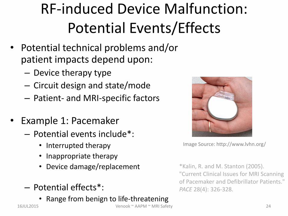
RF-induced Device Malfunction: Potential Events/Effects
• Potential technical problems and/or patient impacts depend upon: – Device therapy type
– Circuit design and state/mode
– Patient- and MRI-specific factors
• Example 1: Pacemaker – Potential events include*:
• Interrupted therapy
• Inappropriate therapy
• Device damage/replacement
– Potential effects*: • Range from benign to life-threatening
16JUL2015 Venook ~ AAPM ~ MRI Safety 24
Image Source: http://www.lvhn.org/
*Kalin, R. and M. Stanton (2005). "Current Clinical Issues for MRI Scanning of Pacemaker and Defibrillator Patients." PACE 28(4): 326-328.

RF-induced Device Malfunction: Potential Events/Effects
• Potential technical problems and/or patient impacts depend upon: – Device therapy type
– Circuit design and state/mode
– Patient- and MRI-specific factors
• Example 2: Neurostimulator – Potential events include*:
• Device reset
• Setting disruption/therapy gap
• Device damage/explant
– Potential effects*: • Range from benign to moderate
16JUL2015 Venook ~ AAPM ~ MRI Safety 25
Image Source: http://www.eastbayspine.com/
*De Andres, J., et al. (2007). "Magnetic Resonance Imaging in Patients with Spinal Neurostimulation Systems." Anesthesiology 106(4): 779-786

RF-induced Device Malfunction: Potential Events/Effects
• Potential technical problems and/or patient impacts depend upon: – Device therapy type
– Circuit design and state/mode
– Patient- and MRI-specific factors
• Example 3: Loop recorder – Potential events include:
• Setting disruption
• Aberrant recording/diagnosis
• Device damage/explant
– Potential effects: • Range from benign to moderate
16JUL2015 Venook ~ AAPM ~ MRI Safety 26
Image Source: http://www.lvhn.org/

RF-induced Artifacts: Mechanisms • B1 shielding
B1 Conductive surface shields RF
Reduced local flip angle/excitation
• B1 distortion
B1 Local electric fields in patient
Coupling of fields to device structures
Induced voltage/current Local Tx/Rx effects
16JUL2015 Venook ~ AAPM ~ MRI Safety 27
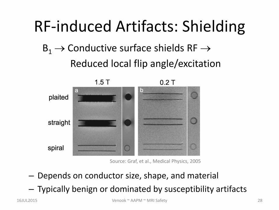
RF-induced Artifacts: Shielding B1 Conductive surface shields RF
Reduced local flip angle/excitation
16JUL2015 Venook ~ AAPM ~ MRI Safety 28
Source: Graf, et al., Medical Physics, 2005
– Depends on conductor size, shape, and material
– Typically benign or dominated by susceptibility artifacts

RF-induced Artifacts: B1 Distortion
B1 Local electric fields in patient
Coupling of fields to device structures
Induced voltage/current Local Tx/Rx effects
16JUL2015 Venook ~ AAPM ~ MRI Safety 29
• Effects can be complex; distant regions of void/enhancement • Different character from susceptibility ‘arrowhead’ artifacts
Source: Nitz, et al. JMRI 2001; 13:105 – 114

Device Interactions/Hazard Summary • Interactions depend significantly on several device
variables—no ‘rules of thumb’ – Length, connectivity/termination, device design,
surrounding tissues, device state, implantation geometry
• Interactions depends significantly on several exposure/patient/MRI variables—no ‘rules of thumb’ – Patient body habitus, orientation/landmark in scanner,
scanner field strength (Larmor frequency), scanner mode
• Potential hazards depend significantly on device and patient specifics – Device type and clinical role
– Stability/dependence of patient
16JUL2015 Venook ~ AAPM ~ MRI Safety 30

Outline
• Motivation
• Types of devices, interactions, and hazards
• Technical example: RF interactions/hazards
• Engineering approaches and perspectives
• Summary and Review Questions
16JUL2015 Venook ~ AAPM ~ MRI Safety 31

Engineering Approaches • Device Engineering
– Leads – Electronics – Software/firmware
• Safety Evaluation Engineering – Exposure and Measurement methods – Modeling methods – Safety acceptability criteria
• MR Clinical/Workflow Engineering – Labeling: Patient screening and scan preparation – FPO:B definition and implementation
16JUL2015 Venook ~ AAPM ~ MRI Safety 32
Device Engineering: Electronics (B0)
• Removing/reducing ferromagnetic materials
– Ferrites in inductors
• E.g., step-up converter, telemetry antenna
– Ferromagnetic materials in components
• E.g., Nickel in capacitor plates, Stainless steel grade
• Removing/replacing magnetically activated components
– E.g., Reed switch -> Hall effect sensor
16JUL2015 Venook ~ AAPM ~ MRI Safety 33

RF Field Mitigation Examples • Goal: Reduce RF heating and/or RF
injection
• Established approaches (on the market) – Reduce or block induced current and
antenna effects • Conductor coiling—tight arrangements, novel
arrangements
– Reduce currents in sensitive locations/components • Shield • Discrete filter
• Conceivable approaches (future?) – ‘Fiber optic’ lead – No lead, microstimulator, etc.
16JUL2015 Venook ~ AAPM ~ MRI Safety 34
Filter
Shield
Coil

Device Malfunction Mitigation Examples
• Input stage design/filtering – E.g., ‘EMI filters’ are common at
pacemaker inputs and can shunt or block aberrant input signals
• Device settings – ‘MRI Mode’ parameter setting
• E.g., Pacemakers turn off sensing, maintain therapy
• E.g., Neurostimulators turn off therapy
– Clinician Programmer or Patient Controller • MRI Mode entry/exit, settings
• Unique use cases 16JUL2015 Venook ~ AAPM ~ MRI Safety 35

Safety Evaluation Engineering
• Characterization methods – Computational/modeling
• Electromagnetic and Thermal
• Complex human/animal models
– Empirical • Transfer function-based (Park/Nyenhuis)
• Safety acceptability criteria – Power-based vs. Temperature-based
– Clinical outcome/effects • E.g., Pacing Capture Threshold
16JUL2015 Venook ~ AAPM ~ MRI Safety 36

MR Clinical/Workflow Engineering
• Goals:
– Patient Safety
• ‘Nobody gets injured due to inappropriate MRI procedures’
– Patient Access
• ‘Patients with MR Conditional devices receive diagnostic benefits of MRI’
• Challenge:
– Existing ‘No access’ safety methods
16JUL2015 Venook ~ AAPM ~ MRI Safety 37

AIMD Patient screening and preparation
• ‘Positive System Identification’ (PSID): Device + components -> Label – PSID Technologies
• Radio-opaque markers = limited role
• Clinician Programmer/Remote Control info
• Patient medical history
• Preparation for scan: Evaluate patient and confirm system configuration/settings – Patient/AIMD Prep Technologies
• Clinician Programmer/Remote Control
• Special-purpose “Activator”
16JUL2015 Venook ~ AAPM ~ MRI Safety 38

MR Clinical/Workflow Engineering
• MR Scanner settings and usage with IMD patients
– FPO:B
• Completing amendment process for IEC 60601-2-33 (3rd Ed.)
• Need implementation
– MR manufacturers (scanners) and AIMD manufacturers (labeling)
16JUL2015 Venook ~ AAPM ~ MRI Safety 39
Physical Parameter FPO:Basic Limit Value
B1+ (peak) 30 μT
B1+ (RMS) 3.2 μT (RMS)
d|B|/dt (peak) 100 T/s
d|B|/dt (RMS) 56 T/s (RMS)

Outline
• Motivation
• Types of devices, interactions, and hazards
• Technical example: RF interactions/hazards
• Engineering approaches and perspectives
• Summary and Review Questions
16JUL2015 Venook ~ AAPM ~ MRI Safety 40

An article in a reputable journal states: “new pacing systems have been specifically designed
for safe use in the MRI environment.” The pacemakers in the article are most likely to
fit which definition:
16JUL2015 Venook ~ AAPM ~ MRI Safety 41
2%
86%
0%
2%
9% A. MR Compatible
B. MR Safe
C. MR Unsafe
D. MR Conditional
E. MR Incompatible
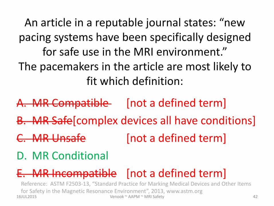
An article in a reputable journal states: “new pacing systems have been specifically designed
for safe use in the MRI environment.” The pacemakers in the article are most likely to
fit which definition:
A. MR Compatible [not a defined term]
B. MR Safe[complex devices all have conditions]
C. MR Unsafe [not a defined term]
D. MR Conditional
E. MR Incompatible [not a defined term]
16JUL2015 Venook ~ AAPM ~ MRI Safety 42
Reference: ASTM F2503-13, “Standard Practice for Marking Medical Devices and Other Items for Safety in the Magnetic Resonance Environment”, 2013, www.astm.org

Which type of MRI field poses the greatest risk to a patient with an implanted device?
16JUL2015 Venook ~ AAPM ~ MRI Safety 43
39%
15%
10%
37%
0% A. Static Field (e.g., 1.5T)
B. RF Field (e.g., SAR [W/kg] or B1+rms [uT])
C. Spatial Field Gradient (e.g., 720g/cm)
D. Time-varying Gradient Field (e.g., 100T/s)
E. Devices have different field interactions/risks

Which type of MRI field poses the greatest risk to a patient with an implanted device?
A. Static Field (e.g., 1.5T)
B. RF Field (e.g., SAR [W/kg] or B1+rms [uT])
C. Spatial Field Gradient (e.g., 720g/cm)
D. Time-varying Gradient Field (e.g., 100T/s)
E. Devices have different field interactions/risks
16JUL2015 Venook ~ AAPM ~ MRI Safety 44
Reference: ISO TS10974: 2012, “Assessment of the safety of magnetic resonance imaging for patients with an active implantable medical device”

Implant Manufacturer Perspective: Summary
• Many (12-18) AIMD/MR interactions – Safety issues highly AIMD-dependent
• Interactions are complex—no ‘rules of thumb’
(unfortunately) – Device-specific experience does not translate to different
devices – e.g., 1.5T vs. 3T; different pacemakers; intact vs. abandoned
leads; etc.
• System design elements
– AIMD components: Leads, Electronics, SW/FW – Workflow and MR system (FPO:B)
16JUL2015 Venook ~ AAPM ~ MRI Safety 45

Implant Manufacturer Perspective: Summary
• Engineering emphasis on assessing and demonstrating safety is as important as design
• Therapy-based engineering constraints are real – MRI-specific changes hard to choose to develop
• MRI safety and access for patients relies on the whole MRI community – MR manufacturers; implantable device manufacturers – MR Technologists; MR Physicists; Radiologists; hospital
admnistrators; referring physicians; etc… – Patients
16JUL2015 Venook ~ AAPM ~ MRI Safety 46

What questions do you have about the implantable device manufacturer
perspective?
16JUL2015 Venook ~ AAPM ~ MRI Safety 47