active damping of transient vibration in dual clutch ... · torque during the final stages of...
TRANSCRIPT

1
Active damping of transient vibration in dual clutch transmission equipped
powertrains: A comparison of conventional and hybrid electric vehicles
Paul D Walker; Nong Zhang
(Faculty of Engineering and Information Technology)
University of Technology, Sydney, Australia
Corresponding author:
Paul D Walker, Faculty of Engineering and Information Technology, University of
Technology, Sydney, 15 Broadway Ultimo, Sydney, Australia 2007
Email: [email protected]
Ph: +61 2 9514 2412

2
Abstract
The purpose of this paper is to investigate the active damping of automotive powertrains
for the suppression of gear shift related transient vibrations. Conventionally, powertrain
vibration is usually suppressed passively through the application of torsional dampers in
dual clutch transmissions (DCT) and torque converters in planetary automatic
transmissions (AT). This paper presents an approach for active suppression of transient
responses utilising only the current sensors available in the powertrain. An active
control strategy for manipulating engine or electric machine output torque post gear
change via a proportional-integral-derivative (PID) controller is developed and
implemented. Whilst conventional internal combustion engine (ICE) powertrains
require manipulation of the engine throttle, for HEV powertrains the electric machine
(EM) output torque is controlled to rapidly suppress powertrain transients. Simulations
for both conventional internal combustion engine and parallel hybrid vehicles are
performed to evaluate the proposed strategy. Results show that while both the
conventional and hybrid powertrains are both capable of successfully suppressing
undesirable transients, the EM is more successful in achieving vibration suppression.
Keywords
Hybrid electric vehicle (HEV), powertrain, active damping, vibration control, dynamics

3
1. Introduction
Major trends in the broader automotive industry are aimed at improving the
efficiency of passenger vehicles through new transmission technologies and
hybridization of the powertrain. Frequently, this excludes the use of powertrain
components such as hydrodynamic torque converters, which possess strong damping
properties in addition to respective functional application. As a result, such vehicles are
increasingly susceptible to driveline oscillations that are perceived by the driver are
poor driving quality, and can be considered a source of noise vibration and harshness
(NVH). The purpose of this study is to investigate the application of active damping
measures for the suppression of these vibrations in the powertrain for both conventional
and hybrid vehicles.
Dual clutch transmission equipped powertrain combine the power-on shifting
capabilities of conventional automatics, such as planetary ATs or continuously variable
transmission (CVT), with the high efficient components of manual transmissions, such
as gears and synchronisers. High quality shift control is required to perform clutch-to-
clutch gearshifts without loss of tractive load to the road, while still providing comfort
and ride quality of the conventional AT. To increase the powertrain efficiency DCTs
eliminate torque converters for the powertrain and consequently loses a significant
component of system damping during shifting. To make use of DCTs in both
conventional internal combustion engine vehicles as well hybrid electric and full

4
electric vehicles, suppression of transient vibration resulting from gear shift is suggested
to improve shift quality.
Extensive research into the control of gear shifts in dual clutch transmissions has
been conducted focusing on the study of control during the shift to limit undesirable
powertrain response [1-4]. This research is commonly limited by simplification of
engine, hydraulic and synchroniser models to provide compact, efficient powertrain
models. As a result it is frequently demonstrated that there is significant torsional
vibration at the completion of shifting, though powertrain damping is sufficient to
reduce vibration after a period of disturbance. The ability to provide rapid and accurate
control of the engine and clutches in such research frequently does not consider the
contributions of time delay in the engine through ignition of pistons or clutch hydraulics
for control of such complex systems. In Walker [5] the integration of detailed hydraulic
models are studied in DCT powertrain shift control, these results indicated that accuracy
of clutch torque estimation is critical to shift control and the manipulation of engine
torque during the final stages of shifting can lead to improvement in shift quality.
However, these results still demonstrate many of the traits of a lightly damped system
with limited suppression of post shift vibration.
Active powertrain damping in conventional ICE powered vehicles has been under
consideration to varying degrees for some time. Berriri [6,7] develops a partial torque
compensator for such vehicles that is independent of many vehicle parameters and

5
external variables (i.e. road grade or aerodynamic drag). The compensator modifies the
engine torque to suppress oscillations. One of the main limitations for suppression in
conventional vehicles is identified as being maintaining vehicle drivability and
responsiveness; insofar that extensive variation in of the engine output torque will
reduce driving quality, implying that there are practical limits to the rate of suppression
which may otherwise result in engine flaring or sluggish response of the vehicle.
Fredriksson [8] has performed a similar study, developing PID, pole placement and
Linear-Quadratic-Gaussion (LQG) controllers, with LQG being demonstrated as the
most successful strategy. Bruce [9] combines feedforward and LQ feedback control and
Lefebvre [10] employs H-infinity control successfully to the same issue. Fredriksson
[11] and Syed [12] both apply active damping to hybrid vehicles. Syed [12] application
is to a power-split HEV utilises active control of motor torque to successfully reduce
vibration to imperceptible levels.
Across each of these studies the dominant trend is to investigate powertrain
oscillations resulting from transients initiated in the variation of throttle control, such as
tip-in/tip-out studies of the powertrain. This paper goes beyond these studies to
integrate control with power-on upshift control of the powertrain. This gear change is
chosen as it the most susceptible to undesirable transients [1]), in comparison to down
shifts and power-off gear change.

6
The high efficiencies and flexibility in design of DCTs make for ideal for application
to hybrid vehicle systems. One example is for mild hybrid systems such as the ESG
presented by Wagner and Wagner [13], where a 10 kW electric machine is used to
improve vehicle efficiencies under high demand or low engine efficiency conditions.
Alternative hybrid systems have been presented by Joshi [14] for a more complicated
hybrid system employing two motors with the DCT used to control power flow of the
system, providing as series-parallel type configuration. Such a design is capable of
much broader operating modes for hybrid operation. Wang [15] present a hybrid
powertrain for application in buses, using various drive cycles to statistically optimise
design, comparisons indicate improved efficiency and mobility compared to popular
integrated starter/generator designs. Kilian [16] provides the most comprehensive
arrangement of hybrid DCT transmissions with electric machines being capable of
placed on input shaft, primary shafts, or countershafts. Uses for these electric machines
include power supply, power generation, and synchroniser assistance. Holmes [17]
provides a simpler hybrid layout for a single electric machine parallel hybrid
arrangement with the electric machine between dual clutches and engine, and capable of
being isolated from the engine using a third clutch.
The purpose of this paper is to therefore use simulation to investigate active damping
of automotive powertrains for conventional and hybrid vehicles, with particular
reference to its implementation with gear shift control. Integration of active damping
7
with shift control exceeds many current studies, which focus on tip-in/tip-out throttle
control as the reference problem for study. Through application of eight degree of
freedom (DOF) powertrain models of various vehicle configurations, the capability to
suppress transients resulting from gear shifting is studied. This includes detailed
modelling of the ICE to capture speed dependent time delay associated with piston
firing [6, 7], and modelling two different parallel HEV configurations.
The remainder of this paper is divided into the following sections. The first section
puts forward detailed modelling of the powertrain and sub components, including the
multi-body dynamic model, torque models for engine, clutches and vehicle resistance
torque. DCT shift control with powertrain vibration suppression is then introduced,
and discussed with reference to implementation. Then several simulations are
conducted to compare shift control strategies and the impact of vibration suppression on
different powertrain configurations. Finally, the paper is summarised and conclusions
are made.
2. DCT equipped powertrain models
2.1. The dual clutch transmission equipped powertrain.
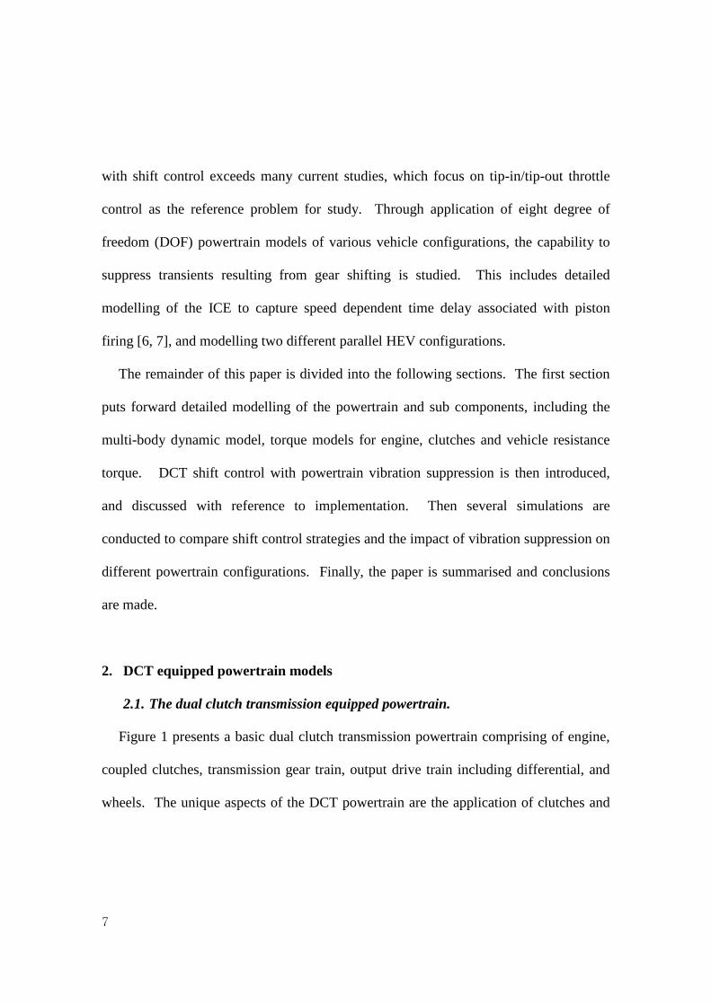
Figure 1 presents a basic dual clutch transmission powertrain comprising of engine,
coupled clutches, transmission gear train, output drive train including differential, and
wheels. The unique aspects of the DCT powertrain are the application of clutches and
8
the arrangement of the gear train. The two clutches have a common drum attached to
the input shaft from the engine, and the friction plates are independently connected to
odd or even gears. For a full transmission gears 1, 3, and 5 (G1) are driven through the
first clutch (C1), while clutch C2 drives gears 2, 4, 6, and R (G2). Synchronisers are
denoted as S1 and S2. Thus, the transmission is representative of two half manual
transmission, and, in this sense, gear change is realised through the simultaneous
shifting between these two half transmissions.
Figure 1: General DCT powertrain layout with different hybridisation variants
Also shown in Figure 1 are the two options considered for the hybridisation of the
DCT powertrain based on the location of the electric machine (EM), these are noted as
EM1 and EM2. These two configurations provide a parallel type hybrid vehicle
powertrain, where the either EM or engine or the two combined can directly drive the
wheels. For the configuration with EM1 the motor speed and torque are defined by the

9
engaged gear ratio, and it is isolated from the transmission and wheels when both
clutches are open. For EM2 configuration, the motor is downstream of the transmission
and therefore has a fixed ratio to the wheels, via the final drive. The limitation to this
configuration being that it is not possible to isolate it from the wheels.
The two aspects of gear shifting are representative of manual and automatic
transmissions. Prior to shifting the first requirement is to synchronise the target gear.
This is realised in an automated process using standard synchronisers that are popular in
manual transmissions, having low cost and high reliability. Once the target gear is
synchronised clutch-to-clutch shifting can be performed. This aspect of shifting applies
similar methods to those performed in automatic transmissions where hydraulically
actuated clutches are simultaneously released and engaged, minimising loss of tractive
load to the road. The most significant change from AT to DCT clutch control is that
there is no longer a hydrodynamic torque converter to dampen any transients developed
during shifting. This therefore requires a much more precise application of clutch
control to ensure shifting is completed within the minimal time with maximum quality.
2.2. Conventional powertrain modelling
Dual clutch transmission equipped powertrains are similar to conventional automatic
powertrains with the exception of no isolation of engine and transmission using the
torque converter. Thus powertrain modelling should consider the application of engine
10
models that contain both output torque and engine harmonics. It is therefore necessary
to create a reasonably complex engine model to capture torque from piston firing as
well as variation in inertia in the moving pistons, connecting rod, and crank shaft. The
powertrain itself does not significantly differ from the proposed powertrain in [5] where
major powertrain components of flywheel, clutch drum, transmission and vehicle
inertias are combined with the engine model to create a compact vehicle powertrain
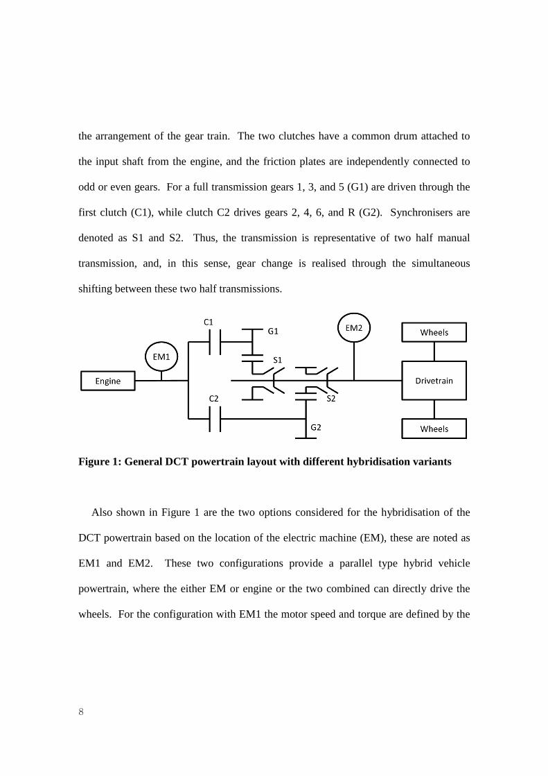
equipped with a DCT. In Fig. 2 below, this model in combined with a four degree of
freedom model of the engine to represent an inline 4 cylinder engine. This model is
structured to achieve clutch-to-clutch shifts between two gears connected to a single
output shaft, presented in Fig. 2, with equations of motion in Eqs. 1-8 in the clutch open
condition.
Figure 2: Eight degree of freedom simplified powertrain model
( ) 121111 EEEEEEEE TKCJ =−−− θθθθ (1)
( ) ( ) 23221222 EEEEEEEEEEE TKKCJ =−−−+− θθθθθθ (2)
TE1
JD, θ
D
JF, θF
TC1
TC2
JV, θV
JT, θT
TV
KD
CD
KT
CT
JE4, θE4
JE3, θE3
JE2, θE2
JE1, θE1
TE2 TE3 TE2
KF KE KE KE
CE CE CE CE g2
g1

11
( ) ( ) 34332333 EEEEEEEEEEE TKKCJ =−−−+− θθθθθθ (3)
( ) ( ) 1443444 EFEFEEEEEEE TKKCJ =−−−+− θθθθθθ (4)
( ) ( ) ( ) 04 =−+−−−− FEFDFDDFDFF KKCJ θθθθθθθ (5)
( ) ( ) 21 CLCLDEDDEDDD TTKCJ −−=−+−+ θθθθθ (6)
( ) ( ) 2211 CLCLVTTVTTTT TTKCJ γγθθθθθ +=−−−− (7)
( ) ( ) VVTTVTTVV TKCJ −=−+−+ θθθθθ (8)
Where J, C, K, γ and T represent inertia, damping, stiffness, gear ratio, and torque,
respectively. Also θ represents the angular displacement of each degree of freedom,
and is complemented by its time derivatives �̇� for velocity and �̈� for acceleration. For
these equations of motion counter-clockwise rotation is taken as the positive direction
of rotation in Eqs. 1 to 6. As the direction of rotation is influenced by reduction gears in
Eqs. 7 and 8 clockwise is taken as the positive direction of rotation. Subscripts E1-4
represents the four engine elements, E is engine, F is flywheel, D is clutch drum, T is
transmission, V is vehicle, and CL refers to clutch 1 or 2. While eqs. 1 to 8 represent
the open clutch model, there are two other transmission states, Clutch 1 closed, and
Clutch 2 closed. For both of these states eqs. 6 and 7 are replaced with eq. 9 for clutch
1 and eq. 10 for clutch 2 closed. As a result the model reduces by one DOF as clutch
drum and transmission elements merge.

12
( ) 0)()()()( 111121 =−+−+−−−−+ TVTTVTFTDFTDDTD CKCKJJ θθθθθθγγθθγγθγ (9)
( ) 0)()()()( 222222 =−+−+−−−−+ TVTTVTFTDFTDDTD CKCKJJ θθθθθθγγθθγγθγ
(10)
2.3. Engine torque models.
Piston firing models of the engine that can be rapidly implemented are available in
Taylor [18], where variation of crank, piston, and connecting rods are defined as a
function of crank angle and crank speed, and by combination with gas torque from
piston firing can be modified to the desired configuration. Fig. 3 presents piston head
pressure at 0 and 100% throttle, linear interpolation is used to vary piston head pressure
for the purpose of throttle control, with the percent throttle determined for each piston at
the beginning of the intake stroke. This model introduces a delay in engine control not
present in look up table models or other methods for simulating the engine output
torque, such as those used in [1,4].
Figure 3: Piston head pressure distribution
13
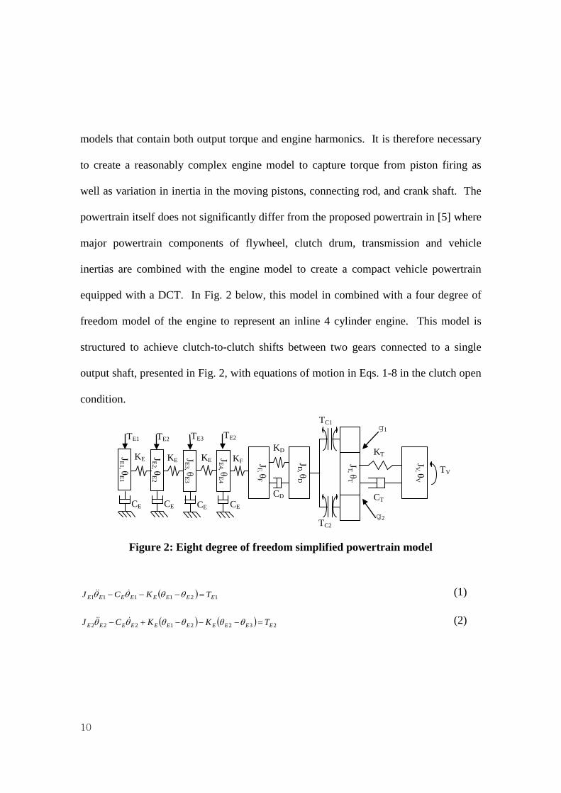
2.4. Clutch torque model
Clutch torque is defined using the piecewise clutch model presented in [5]. This
determines clutch state and is based on the stick-slip algorithm with four elements
relating clutch piston displacement, slip speed and average torque in the clutch. The
piecewise clutch model is:
03 30
02 20
0 ,
3 30
0 ,2 20
0
, 0*
, 0*,
, 0*,
ID A
IC
avg avg C S
IS A avg C S
I
X X
r rn F X X
r rT
T X X T T
r rn F X X T T
r r
µ θ
θ
µ θ
<
− × ≥ D ≥ −= ≥ D < <
− × ≥ D < ≥ −
(11)
Where, n is the number of friction plates, X is piston displacement and X0 is the
minimum displacement required for contact between friction plates, μD is dynamic
friction, μS is static friction, r0 and rI are the outside and inside diameters of the clutch
plates, and FA is the pressure load on the clutch. Tavg is the average clutch torque
derived from the model dynamics using the equations of motion (1-8), as follows
1 1
2C a C b
avgT T
T+
= (15)
1,21 )()( CEDDEDDDDaC TCKJT −−−−−−= θθθθθ (16)
( ) 2,11,21,21 )()( γγθθθθθ CTVTTVTTTbC TCKJT +−+−+−= (17)

14
2.5. Vehicle resistance torque model
Vehicle torque models are well established, comprising of rolling friction losses,
aerodynamic drag, and the impact of road incline. The vehicle torque is derived as:
WTvDvairvV RgfMVCAgMT ×
++= 2
21)sin( rϕ
(18)
Where Mv is vehicle mass, g is gravity, φ is angle of inclination, Av is vehicle area,
CD is drag coefficient, V is vehicle speed, ρair is air density, and fT rolling resistance
coefficient.
2.6. Hybrid configuration and modelling
The flexibility of hybrid vehicles with many choices in engine/electric machine
configuration enables the study of different electric machine locations on vehicle
performance and the impact on transient vibration suppression. In this section two
configurations are considered. The electric machine will be positioned at the flywheel
in Case 1, see Fig. 4 (a), and in Case 2 it is located on the output shaft, see Fig. 4 (b).
This enables different methods for evaluating torsional vibration suppression where the
electric machine will have variable torque multiplication through the transmission when
located at the flywheel, and constant torque multiplication if located at the output shaft.

15
Figure 4: 8-DOF hybrid vehicle powertrain model, (a) electic machine located at the flywheel, and (b) electric machine located at the DCT output shaft
The two powertrain configurations presented in Fig. 4 are two of a range of options for
locating the electric machine for hybrid vehicle powertrains. In Fig. 4 (a) the electric
machine is located with the engine at the flywheel, such configurations result in the EM
torque being multiplied through the currently engaged gear depending on shift
requirements. However, depending on EM sizing and a range of design considerations,
it is also convenient to locate the EM at the output shaft of the transmission using a
constant gear ratio for power conversion; this is shown in Fig 4. (b). In this
TE1
JD
JF
TC1
TC2
JV
JT TV
KD
CD
KT
CT
JE4
JE3
JE2
JE1
TE2 TE3 TE2
KF KE KE KE
CE CE CE CE
TEM (a)
g2
g1
TE1 JD
JF
TC1
TC2
JV JT TV
KD
CD
KT
CT
JE4
JE3
JE2
JE1
TE2 TE3 TE2
KF KE KE KE
CE CE CE CE
TEM (b)
g2
g1 gEM

16
configuration torque is multiplied by a constant ratio over the entire vehicle speed
range.
For both models the engine torque is derived from lookup tables of EM efficiency and
output torque for a desired power and speed. Eqs. 5 and 7 must be modified to include
engine torque for the models in Fig. 4 (a) and Fig. 4(b), respectively.
( ) ( ) ( ) EMFEFDFDDFDFF TKKCJ =−+−−−− θθθθθθθ 4 (19)
( ) ( ) EMEMCLCLVTTVTTTT TTTKCJ γγγθθθθθ ++=−−−− 2211 (20)
3. Integration of active powertrain damping with up-shift control strategy
There are a number of considerations required for implementing the control strategy
and its integration with gear shift control. It is well established that powertrain
oscillations will be observable during transient driving conditions, such as tip-in/tip-out,
clutch engagement, or in the presence of backlash excitation. For the time being, both
tip-in and backlash aspects of this study are excluded as studies by Berriri [6,7] and
Bruce [9] have already considered these issues. For the purposes of this paper only
upshift control is considered, this is usually the most critical component of shifting as it
frequently occurs under hard acceleration, and poor shifts will be more observable.
Key to the implementation of any minimise the requirement for additional sensor
requirements. The modern automotive powertrain has a number of speed sensors,

17
including at the engine flywheel, transmission output and wheel hubs. Respectively,
these are employed for engine, shift and launch control and anti-lock braking control.
Active damping of the powertrain can then utilise any of these three sensors to supress
transients resulting from gear change.
The complete up shift in a DCT equipped powertrain is shown in Fig. 5 and can be
divided into four steps, these are as follows:
1. Shift preparation –The synchroniser is engaged for the target gear. Then the
engaging clutch hydraulic cylinder is filled with fluid to the point of contact
in friction plates. At the same time the releasing clutch pressure is reduced
such that the clutch static friction torque approaches the friction limit
according to eq. 11.
2. Torque phase – The engaging and releasing clutch torques are manipulated to
transfer driving torque load to the engaging clutch, requiring estimation of the
torque driving the vehicle through the engaging clutch as a reference load. It
is common in this step for engine torque to be manipulated to minimise
torque hole during shift [1].
3. Inertia phase – This is when primary driving load is on the engaging clutch
and slip speed in the friction plates are synchronised to complete the shift.
Transmission output speed control is used to minimise vibration during gear

18
shift, and engine torque manipulation is used to control the duration of shift
time.
4. Post shift damping – After clutch lockup powertrain oscillations are
suppressed using speed sensor inputs and modifying either the engine or
motor output torque, depending on the powertrain configuration.
Figure 5: Flow chart of shift control for up shifting in a DCT

19
4. Simulations of shift control of DCT equipped powertrains
4.1. A comparison of shift control with and without slip speed control
To demonstrate the shift process in the DCT the model configuration in Fig. 2 is used
in conjunction with the described shift process in steps 1-4 above, with clutch hydraulic
model derived in Walker [5]. The selected gears are 3rd engaged in the transmission
with 4th targeted for the up shift. Initial engine speed is 400 rad/s, equating to a vehicle
speed of approximately 88 rad/s. These conditions are maintained for the remaining
simulations in this paper.
The shift transient results are presented in Fig. 6 with clutch speeds in (a) and vehicle
and transmission speeds in (b). Clutch fill takes approximately 100ms as C2 piston is
filled to contact in the friction plates in the wet clutch, while the torque phase takes
approximately 50ms. At this point the inertia phase begins and the clutch drum speed is
reduced to clutch 2 speed. The results demonstrate that the slip speed control is capable
of reducing vibration rapidly during the inertia phase before the clutches lockup. As
indicated in Fig. 6 (b) there is still significant response in the powertrain resulting from
clutch lockup, and low damping between vehicle and transmission results in limited
reduction of the response. The results are fairly for typical simulated clutch-to-clutch
shifting in DCTs, with the inclusion of higher frequency forced vibration from the
engine model.

20
Figure 6: Shift dynamics of a DCT equipped powertrain using the shift process
described in Fig. 5, (a) clutch speeds, and (b) vehicle speed
To demonstrate the importance of the combination of torque and speed control in
DCTs equivalent simulations to those presented in the previous section are conducted
without the inclusion of slip speed control in the inertia phase. The exclusion of slip
speed control is equivalent of the clutch pressure being controlled during the torque
phase to hit the mean torque, and in the inertia phase, being maintained at its mean
torque with no additional control to suppress vibration in the inertia phase. These
results, shown in Fig. 7, demonstrate that the exclusion of slip speed control increases
the powertrain vibration upon shift completion. The primary change to simulations in
Fig. 6 is the continuation of vibration in the transmission at comparatively high
0.5 1 1.5 2300
350
400
450
Rot
atio
nal
spee
d (ra
d/s)
Time (s)
Clutch DrumClutch 1Clutch 2
0.5 1 1.5 285
90
95
100
Rot
atio
nal
spee
d (ra
d/s)
Time (s)
TransmissionVehicle
(a)
(b)

21
amplitude in the transmission. As a consequence, the resulting post shift vibration is
significant in the powertrain, particularly when comparing Fig 6 (b) to Fig. 7 (b).
It is worth noting here, that the additional inertia phase control to reduce transient
response during the shift results in additional reduced deceleration of the clutch drum
through comparison of Fig. 6 (a) to Fig. 7 (a). This results from variation in clutch 2
torque to reduce powertrain vibration. Nevertheless, the study shows that combined
torque phase and inertia phase control can be used to significantly improve powertrain
response during shifting.
Figure 7: Shift dynamics of a DCT equipped powertrain using the shift process
described in Fig. 5 with slip speed control (Fig 5 point 3A) disabled, (a) clutch
speeds, and (b) vehicle speed
0.5 1 1.5 2300
350
400
450
Rot
atio
nal
spee
d (ra
d/s)
Time (s)
Clutch DrumClutch 1Clutch 2
0.5 1 1.5 285
90
95
100
Rot
atio
nal
spee
d (ra
d/s)
Time (s)
TransmissionVehicle
(a)
(b)

22
The combination of alternate control strategies during the inertia and torque phases
also improves powertrain response. However, these results in Fig. 6 and 7 also
demonstrate that torsional vibration is not completely eliminated using alternate clutch
control strategies. This suggests that additional measures are required to achieve
maximum possible shift quality in DCT equipped powertrains.
4.2. Vibration suppression with engine control for a conventional powertrain
After the shift completes there is obvious response in the powertrain, which is caused
by the change in several powertrain variables, e.g., primarily engine speed and inertia in
the transmission, but also potentially results from inaccuracy in output torque estimation
for clutch control. To suppress the powertrain response it is suggested here that the
variation of engine torque can be used to suppress this response.
Fig. 8 represents the suggested control strategy for manipulating engine output
torque to suppress the powertrain vibration. It makes use of the difference between
vehicle and transmission speeds to modify the driver demand signal and control engine
output torque. Relative speeds are chosen at this point as the oscillation between
transmission and vehicle inertias is indicative of poor powertrain response that can be
observed by the driver. To compensate for the relative speed in the powertrain the PID
control supplies a signal output that is superimposed with driver demand, while driver
demand is limited to 85% throttle such that the controller can make use of increasing

23
and decreasing engine torque to actively reduce vibration without significantly flaring
throttle, resulting in abrupt variation in engine speed.
Figure 8: Engine control strategy for DCT vibration suppression
Figure 9: Shift dynamics of a DCT equipped powertrain using the shift process
described in Fig. 5 using vibration suppression in the engine, (a) clutch speeds, and
(b) vehicle speed
0.5 1 1.5 2300
350
400
450
Rot
atio
nal
spee
d (ra
d/s)
(a)
Time (s)
Clutch DrumClutch 1Clutch 2
0.5 1 1.5 285
90
95
100
Rot
atio
nal
spee
d (ra
d/s)
(b)
Time (s)
TransmissionVehicle
Control signal
Driver input
Output torque
PID Controller +
- Engine
Vehicle speed
Transmission speed
Error Suppression signal
+ +

24
Simulation results shown in Fig. 9 and Fig. 10 demonstrate the application of engine
control to suppress torsional vibration in the vehicle powertrain. Here the powertrain is
modelled according to Eqs. 1-8, and the standard shift control strategy are used with the
addition of engine throttle manipulation, the goal being the rapid reduction of vibration
in the vehicle powertrain. The results are quite promising; with the rapid reduction of
vibration in the vehicle speed after gear shift is completed. In Fig. 9 (a) results show
comparable shift transients to Fig. 6 (a), however by the completion of the first period
of oscillation after shifting is complete there is significant suppression of vibration at
this clutch. This result continues through to the transmission and vehicle speeds, with
vibration in the vehicle speed rapidly suppressed. Complementing these results is the
instantaneous piston torques and throttle control results in Fig. 10 (a) and (b),
respectively. It is important to note here that at the completion of shift it takes two
piston firings in the engine before output torque increases, suggesting that time delay is
an important factor in engine control for DCTs. These results suggest that the
application of engine throttle control can be used to rapidly suppress powertrain
vibration post gear shift in DCT equipped powertrain.

25
Figure 10: Engine output and control corresponding to Fig. 10. (a) Gas and inertia
torque for individual pistons, and (b) throttle angle manipulation for vibration
suppression
For comparative purposes engine control is also conducted using clutch control
without inertia phase control, here clutch torque is maintained at a mean torque, similar
to the simulation in Fig. 7. While the transient period is very similar, the post shift
response is significantly improved, within two vibration periods the oscillations are
suppressed. Giving the amplitude of transmission vibration in Fig. 7 (b) this is a very
important result, as significantly higher oscillations are suppressed in a similar duration
to those of a much more successful shift. Thus these simulation results in Figs. 9 to 10
demonstrate that is the application of engine throttle manipulation for suppression of
1 1.1 1.2 1.3 1.4 1.5 1.6 1.7 1.8 1.9 2-200
0
200
400
600
Inst
anta
neou
s pi
ston
torq
ue (N
m)
Time (s)
1 1.1 1.2 1.3 1.4 1.5 1.6 1.7 1.8 1.9 20
50
100
Thro
ttle
(%)
Time (s)
(a)
(b)

26
powertrain response can be used to improve the shift quality of a lightly damped
powertrain, actively controlling vibration response in a lightly damped powertrain.
4.3. Vibration suppression with an electric machine for a hybrid vehicle
The two hybrid vehicle powertrain configurations presented previously provide
alternative methods for active controlling of the powertrain response. The application
of an electric machine to active vibration suppression has significant advantage in terms
of less time delay and more controlling torque than that of an internal combustion
engine in which throttle response limits the capability for output torque variation. The
EM control method for vibration suppression is presented in Fig. 11, here vibration
between vehicle and transmission is detected and torque suppression requirements are
requested from the EM. Unlike vibration suppression with the engine, engine control
remains with the driver and EM torque independently suppresses vibration. Thus the
driver is less likely to notice the effect of vibration suppression on vehicle performance
than would be the case with engine throttle manipulation.
Figure 11: EM control strategy for DCT vibration suppression
Driver input
Output torque PID
Controller + -
+ +
Motor
Vehicle speed
Transmission speed
Error Suppression signal
Motor torque
Engine
Engine torque

27
To demonstrate the effectiveness of the use of the EM for vibration suppression,
simulations are presented in the following two figures. Fig. 12 presents results for
vibration suppression using the hybrid vehicle configuration presented in Fig. 4 (a),
while Fig. 13 presents the results for Fig. 4 (b). For these simulations the controller
used has inertia phase control deactivated to present a worst case scenario, and initial
EM and vehicle speeds are 400 rad/s and 88 rad/s respectively.
The simulation results for the hybrid vehicle configurations demonstrate a capability
to rapidly suppress transient response in the powertrain after gearshift completes. The
combination of slip speed control and vibration suppression is to rapidly reduce
undesirable transient vibration in the powertrain. In Fig. 12 (b) the transmission speed
drops below the nominal vehicle speed after the completion of shifting, and the EM
rapidly counters the introduced vibration by supplying torque to accelerate the
transmission to the nominal speed and suppress vibration. These results are further
improved in Fig. 13 (b) with the location of the EM capable of directly impacting on
powertrain response.

28
Figure 12: Response of a hybrid DCT equipped powertrain for the configuration
in Fig 4. (a), using an electric machine for vibration control, (a) clutch speeds, and
(b) vehicle speed
Figure 13: Response of a hybrid DCT equipped powertrain for the configuration
in Fig 4. (b), using an electric machine for vibration control, (a) clutch speeds, and
(b) vehicle speed
0.5 1 1.5 2300
350
400
450
Rot
atio
nal
spee
d (ra
d/s)
(a)
Time (s)
Clutch DrumClutch 1Clutch 2
0.5 1 1.5 290
95
100
Rot
atio
nal
spee
d (ra
d/s)
(b)
Time (s)
TransmissionVehicle
0.5 1 1.5 2300
350
400
450
Rot
atio
nal
spee
d (ra
d/s)
(a)
Time (s)
Clutch DrumClutch 1Clutch 2
0.5 1 1.5 290
95
100
Rot
atio
nal
spee
d (ra
d/s)
(b)
Time (s)
TransmissionVehicle
29
5. Conclusion
The control of shifting in dual clutch transmission equipped powertrains has been
studied in this paper. To conduct this research a powertrain model is presented with
detailed engine model, such that the engine torque variation resulting from piston firing
is simulated, while a more compact look-up table is used for motor torque. These
strategies are utilised to demonstrate the variation in delay between internal combustion
engines and electric motors, with the EM being capable of faster response to variation in
torque demands. Simulations of shift control with and without inertia phase control of
the clutches for a conventional powertrain demonstrated the importance of inertia phase
on minimising powertrain vibration during and after shifting. Implying that variations
in the quality of gear shift can be significant. The obtained results show that it was not
possible to completely eliminate the transient vibration in the powertrain, even when
using inertia phase control.
To suppress the post shifting powertrain vibration, which is introduced at the
completion of clutch changeover, active vibration control using the engine for
conventional powertrains, and an electric motor for hybrid vehicle powertrains is
suggested. This vibration suppression makes use of variation in engine or EM output
torque to suppress powertrain response after gearshift. The results of engine control
demonstrate the capability to successfully suppress these vibrations rapidly; however
control is limited by delay in piston firing and the ability to supply high torque variation

30
while maintaining vehicle speed. Application of the same strategy to hybrid vehicles
was also successful regardless to the location of electric machine. The higher torque
available in the EM combined with significantly less time delay also contributes to the
improved control. These results have demonstrated that active engine or EM control
can be used to successfully suppress vibration in vehicle powertrains where there is
traditionally insufficient damping to provide rapid passive vibration suppression.
Acknowledgements
This project is supported by BAIC Motor Electric Vehicle Co.Ltd, the Ministry of
Science and Technology, China, and University of Technology, Sydney.
References
[1] M. Goetz: Integrated powertrain control for twin clutch transmissions, PhD thesis,
University of Leeds (2005).
[2] Y. Zhang, X. Chen, H. Jiang, and W. Tobler, Dynamic modelling and simulation of
a dual clutch automated lay shaft transmission, J. Mech. Des. 127 (2005): 302-307.
[3] Y. Liu, D. Qin, H. Jiang and Y. Zhang A systematic model for dynamics and control
of dual clutch transmissions, J. Mech. Des. 131 2010: 061012.
[4] M. Kulkarni, T. Shim, and Y. Zhang. Shift dynamics and control of dual clutch
transmissions Mech. Mach. Theory 42 (2007) 168-182.

31
[5] P.D. Walker, N. Zhang, and R. Tamba Control of gearshifts in dual clutch
transmission powertrains. Mech. Sys. Signal Process. 25 (2010) 1923-1936.
[6] M. Berriri, P. Chevrel, D. Lefebvre, and M. Yagoubi, (2007) Active damping of
automotive powertrain oscillations by a partial torque compensator. In: American
Control Conference, New York USA, 9-13 July: 5718-5723.
[7] M. Berriri, P. Chevrel, and D. Lefebvre, Active damping of automotive powertrain
oscillations by a partial torque compensator, Control Eng. Pract., 16(7) (2008) 874-883.
[8] J. Fredriksson Improved driveability of a hybrid electric vehicle using powertrain
control, Int. J. Altern. Prop., 1(1) (2006) 97–111.
[9] M. Bruce, B. Egardt, and S. Pettersson, (2005) On powertrain oscillation damping
using feedforward and LQ feedback control. In: Proceedings of 2005 IEEE Conference
on Control Applications, Toronto, Canada. 2005, 28-31 August pp. 1415-1420.
[10] D. Lefebvre, P. Chevrel and S Richard. An H-infinity-based control design
methodology dedicated to the active control of vehicle longitudinal oscillations, IEEE
Trans. Cont. Sys. Tech., 11(6) (2003), 948-956.
[11] J. Fredriksson, H. Weiefors and B. Egardt, Powertrain Control for Active Damping
of Driveline Oscillations, Veh. Sys. Dyn., 37(5) (2008) 359-376.
[12] F.U. Syed, M. L. Kuang, and H Ying, Active Damping Wheel-Torque Control
System to Reduce Driveline Oscillations in a Power-Split Hybrid Electric Vehicle IEEE
Trans. Veh. Tech., 58(9) (2009) 4769-4785.

32
[13] U. Wagner and A. Wagner, (2005) Electric shift Gearbox (ESG) - consistent
development of the dual clutch transmission to a mild hybrid system, SAE Technical
Paper: 2005-01-4182.
[14] A.S. Joshi, N. P. Shah, C. Mi, (2009) Modelling and simulation of a dual clutch
hybrid vehicle powertrain, in: Vehicle power and propulsion conference, Michigan
USA, 7-10 Sept: 1666-1673.
[15] J. Wang, J. Guo, G. Ao, L. Yang, B. Zhuo, Simulation of a single-axle parallel
hybrid electronic system with two clutches, Journal of Shang Hai Jiao Tong University,
42(6) (2008) 882-886
[16] S. Kilian, S. Pascual, (2007) Dual-clutch transmission with integrated electric
machine and utilization thereof, US Patent application 2007/0022835 A1.
[17] A. G. Holmes, (2010) Hybrid powertrain and dual clutch transmission, US Patent
application 2010/0179024 A1.
[18] C. F. Taylor (1985) Internal combustion engines in theory and practice, Volume 2:
Combustion, fuels, materials, and design, MIT Press, 2nd Edition.