active and reactive power control of a 15-level inverter ... · reactive power transfer to the grid...
TRANSCRIPT
© 2017 IJEDR | Volume 5, Issue 2 | ISSN: 2321-9939
IJEDR1702242 International Journal of Engineering Development and Research (www.ijedr.org) 1540
Active and Reactive Power control of a 15-level Inverter with
FACTS Capability for Distributed Energy Systems 1B.Naga Seshu, 2V.Vani, 3S.Ravikanth
1Assistant Professor (EEE), DVR&Dr.HS MIC College of Technology, Kanchikacherla, A.P India 2PG Scholar (EEE), DVR&Dr.HS MIC College of Technology, Kanchikacherla, A.P India
3Assistant Professor (EEE), DVR&Dr.HS MIC College of Technology, Kanchikacherla, A.P India
Abstract-In this paper, a new single-phase wind energy
inverter (WEI) with flexible Ac transmission system
(FACTS) capability is presented. The proposed inverter is
placed between the wind turbine and the grid, same as a
regular WEI, and is able to regulate active and reactive
power transferred to the grid. This inverter is equipped with
distribution static synchronous compensators option in
order to control the power factor (PF) of the local feeder
lines. Using the proposed inverter for small-to medium- size
wind applications will eliminate the use of capacitor banks
as well as FACTS devices to control the PF of the
distribution lines. The goal of this paper is to introduce new
ways to increase the penetration of renewable energy
systems into the distribution systems. I Considered a single
phase voltage sources in the series RLC Branch at the grid
side, similarly a single-phase asynchronous Machine are
placed at Load side, the d-stastcom and Pv cell are placed in
between AC Voltage source and wind turbine. In this paper
modular multilevel converter is utilized to meet all the
requirements of IEEE standards the total harmonics
distortion (THD), Active and Reactive of the system are
calculated. The proposed 15-level inverter is a single-phase
wind energy inverter is placed between the wind turbine and
the grid, The function of inverter can manage active and
reactive power transfer to the grid and wind turbine, as well
as keeping Pf constant at wind turbine. Active and Reactive
power from the grid, Turbine and inverter side was
calculated, and also calculated line voltage of wind turbine
and Inverter. The simulation Results of a 15-level inverter
have been done in MATLAB/Simulink.
Keywords: Modular multilevel converter (MMC), multilevel
inverter (MLI), Wind energy inverter (WEI)
I. INTRODUCTION
Power electronics is the major field in electrical and
electronics engineering which are used in semiconductor
devices to convert power from the source to the corresponding
load requirement. The load may be differs according to its
applications i.e. DC or AC, single and three phase and also
depends upon its isolation. Mainly used power source are AC
and DC source, batteries, solar panel, generators and also for
commercial uses. Single and three phase are having line
frequency about 50 or 60 HZ. Power converters are used here to
convert the power from source to the form required by the load.
The commonly used power converters are AC-DC converter, a
DC-DC converter, a DC-AC inverter or an AC-AC converter
depending on the application.
II. CASCADED H BRIDGE MULTILEVEL INVERTER
INVERTER
An electrical device that converts DC to AC current is called
Inverter. In home inverter is used for back up process. It is also
used in aircraft for converting direct current to alternative
current. In general, AC power is commonly used in applications
like radio, radar, motor etc.
MULTILEVEL INVERTER
Now a days the industrial needs are raised to have high power
in their applications. But still some appliances power
requirement is medium or low to run their operation. By using
high power in all industries load is good for only some motors
which requires high power. But it will damage the other loads.
Because applications that run on medium power source requires
only medium voltage. Hence multi level inverter has introduced
in 1975 to have both high and medium.
DC-AC INVERTER
The basic need of multilevel inverter is to have high power
output from medium voltage. Some of the medium voltage
sources are batteries, super capacitors, solar panel are medium
voltage source. These inverters consist of number of switches.
These switches angle arrangement in an inverter is the most
important while designing.
Multilevel inverters are three types.
1) Diode clamped multilevel inverter
2) Flying capacitors multilevel inverter
3) Cascaded H- bridge multilevel inverter
The five level multilevel inverter of diode clamped uses diode,
switches, and one capacitor is used. So that the output voltage is
half of the supply voltage DC. The 9 level inverter consists of
elements like diodes, capacitors and switches. In this inverter
the output voltage is more than five level inverter.

© 2017 IJEDR | Volume 5, Issue 2 | ISSN: 2321-9939
IJEDR1702242 International Journal of Engineering Development and Research (www.ijedr.org) 1541
III.FIFTYTEEN LEVEL CASCADED H-BRIDGE MULTI
STRUCTURE DIODE CLAMPED MULTILEVEL
INVERTER
The diode clamped multilevel inverter provides multiple
voltage level by the use of diode through the capacitor bank
which are connected in series. The stress of the electrical
devices is reduced by transferring limited level of voltage in
diode. The input DC voltage is the half of the maximum output
voltage. This is the disadvantage of the diode clamped
multilevel inverter. This drawbacks can be overcomes by
increasing the diode, switches and capacitors. The high
efficiency is provided by this type of inverter due to the
fundamental frequency for all switching devices. It is the easy
method for the back to back power transfer topology. The five
level multilevel inverter of diode clamped uses diode, switches,
and one capacitor is used. So that the output voltage is half of
the supply voltage DC. The 9 level inverter consists of elements
like diodes, capacitors and switches. In this inverter the output
voltage is more than five level inverter.
FLYING CAPACITORS MULTILEVEL INVERTER:
The concept of multi inverter with flying capacitor use
capacitors. It is connected in series with the switching cell of
capacitor clamped. The capacitor will transfer little amount of
voltage to electrical devices. The switching state of this inverter
is same as the diode clamped multilevel inverter. The output
voltage is determined by half of the input DC voltage. This is
the disadvantage of multi-level inverter with flying capacitor. It
balance the switching redundancy of the flying capacitor. It also
controls active and reactive power which flows in a circuit.
Switching losses occurs due to high frequency switching. Here
switches and capacitors only used.
CASCADED H-BRIDGE MULTILEVEL INVERTER:
In H-Bridge cascaded multi level inverter less number of
switches are used and the inverter use capacitor and switches for
the designing process. This method in multi level inverter
includes power conversion cells that are connected in series and
power is scaled. The combined capacitors and switches make H-
Bridge. Each H-Bridge inverter supplied with separate DC
supply. H-Bridge inverter consists of cells where each cell
consists of zero voltage, positive DC voltage and negative DC
voltage. Compared with other type multi level inverter like
diode clamped and flying capacitor, H-Bridge has the advantage
of having fewer components.
Fig. 1. Complete configuration of the proposed inverter with
FACTS capability.
In this paper, the proposed WEI utilizes MMC topology,
which has been introduced recently for HVDC applications.
Replacing conventional inverters with this inverter will
eliminate the need to use a separate capacitor bank or a
STATCOM device to fix the PF of the local distribution grids.
Obviously, depending on the size of the power system, multiple
inverters might be used in order to reach the desired PF. The
unique work in this paper is the use of MMC topology for single
phase voltage-source inverter, which meets the IEEE standard
519 requirements, and is able to control the PF of the grid
regardless of the wind speed Fig. 1 shows the complete grid
connected mode configuration of the proposed inverter. The dc
link of the inverter is connected to the wind turbine through a
rectifier using MPPT and its output terminal is connected to the
utility grid through a series-connected second-order filter and
loads and the Ac Synchrocus machine.
MODULAR MULTILEVEL CONVERTER
MMC has gained increasing been recently. A number of
papers were published on the structure, control, and application
of this topology, but none has suggested the use of that for
inverter + DSTATCOM application. This topology consists of
several half-bridge (HB) sub modules (SMs) per each phase,
which are connected in series. An n-level single phase MMC
consists of a series connection of 2(n − 1) basic SMs and two
buffer inductors. Each SM possesses two semiconductor
switches, which operate in complementary mode, and one
capacitor. The exclusive structure of MMC becomes it an ideal
candidate for medium-to-high-voltage applications such as
wind energy applications. Moreover, this topology needs only
one dc source, which is a key point for wind applications. MMC
requires large capacitors which may increase the cost of the
systems; however, this problem is offset by the lack of need for
any snubber circuit. Figure 2: Structure of a single-phase MMC
inverter structure. The main benefits of the MMC topology are:
modular design based on identical converter cells, simple
voltage scaling by a series connection of cells, simple

© 2017 IJEDR | Volume 5, Issue 2 | ISSN: 2321-9939
IJEDR1702242 International Journal of Engineering Development and Research (www.ijedr.org) 1542
Figure 2: Structure of a single-phase MMC inverter structure.
Applications such as wind energy applications. Moreover, this
topology needs only one dc source, which is a key point for wind
applications. MMC requires large capacitors which may
Increase the cost of the systems; however, this problem is offset
by the lack of need for any snubber circuit. The main benefits of
the MMC topology are: modular design based on identical
converter cells, simple voltage scaling by a series connection of
cells, simple realization of redundancy, and possibility of a
common dc bus. Fig. 2shows the circuit configuration of a
single-phase MMC and the structure of its SMs consisting of
two power switches and a floating capacitor. The output voltage
of each SM (vo) is either equal to its capacitor voltage (vc) or
zero, depending on the switching states. The buffer inductors
must provide current control in each phase arm and limit the
fault currents.
Generally, when Sui or Sli is equal to unity, the i Th upper or
lower SM is ON; otherwise it is OFF. Therefore, the upper and
lower arm voltages of the MMC are as follows:
11v)
civ
1n
1iui
(sUpperArm
V
(1)
12v)
civ
1n
1i li(s
UpperArmV
(2)
where v11 and v12 are the voltages of the upper and lower buffer
inductors, n is the number of voltage levels, and vci is the
voltage of the i th SMs capacitor in upper arm or lower arm. A
single-phase 15-levelMMC inverter consists of 20 SMs which
translates to 40 power switches, 20 capacitors, and 2 buffer
inductors. The dc and ac voltages of the 15-level MMC are
described by
lowerArmV
upperArmV
DCV
)12
V11
(V)ci
Vui
S10
1i()
10
1i ciV
ui(S
(3)
lowerArmV
2
DCV
UpperArmV
2
DCV
outV (4)
PROPOSED CONTROL STRATEGY
The proposed controller consists of three major functions.
The first function is to control the active and reactive power
Fig 3 Schematic of the Proposed Controller System.
Transferred to the power lines, the second function is to keep
the voltages of the SMs’ capacitors balanced, and the third
function is to generate desired PWM signals. Fig. 2 shows the
complete proposed controller system. The aim of the designed
inverter is to transfer active power coming from the wind turbine
as well as to provide utilities with distributive control of volt-
ampere reactive (VAR) compensation and PF correction of
feeder lines. The application of the proposed inverter requires
active and reactive power to be controlled fully independent, so
that if wind is blowing, the device should be working as a
normal inverter plus being able to fix the PF of the local grid at
a target PF (D-STATCOM option), and if there is no wind, the
device should be only operating as a D-STATCOM (or
capacitor bank) to regulate PF of the local grid. This translates
to two modes of operation: 1) when wind is blowing and active
power is coming from the wind turbine: the inverter plus D-
STATCOM mode. In this mode, the device is working as a
regular inverter to transfer active power from the renewable
energy source to the grid as well as working as a normal D-
STATCOM to regulate the reactive power of the grid in order to
control the PF of the grid and 2) when wind speed is zero or too
low to generate active power: the D-STATCOM mode. In this
case, the inverter is acting only as a source of reactive power to
control the PF of the grid, as a D-STATCOM. This option
eliminates the use of additional capacitor banks or external
STATCOMs to regulate the PF of the distribution feeder lines.
Obviously, the device is capable of outputting up to its rated
maximum real power and/or reactive power, and will always
output all real power generated by the wind turbine to the grid.
The amount of reactive power, up to the design maximum, is
dependent only on what the utility asks the device to produce.

© 2017 IJEDR | Volume 5, Issue 2 | ISSN: 2321-9939
IJEDR1702242 International Journal of Engineering Development and Research (www.ijedr.org) 1543
Generally, (5) and (6) dictate the power flow between a
STATCOM device and power lines
sinX
EEP LS
s (5)
2L
EcosδL
ES
ES
Q (6)
Where X is the inductance between the STATCOM (here as
inverter) and the grid which is normally considered as output
filter inductance added to the transmission line inductance. The
root mean square (RMS) voltage of the STATCOM (= inverter)
is given as Es and is considered to be out of phase by an angle
of δ to the RMS line voltage E1. In the proposed control
strategy, active and reactive power transferred between the
inverter and the distribution grid is controlled by selecting both
the voltage level of the inverter and the angle δ between the
voltages of inverter and grid, respectively. The amplitude of the
inverter voltage is regulated by changing the modulation index
m and the angle δ by adding a delay to the firing signals which
concludes.
sinδX
LE
SmE
SP (7)
X
2L
EcosδL
ES
mE
SQ
(8)
In this paper, m is the key factor to control the reactive power
compensation and its main task is to make the PF of the grid
equal to the target PF. δ is the control parameter to adjust the
active power control between the inverter and the grid. Several
assumptions should be considered for the proposed controllers
which are as: 1) the load on the feeder line should be considered
fixed for a small window of time and there is no change in the
load during a cycle of the grid frequency; 2) the feeder line can
be accurately modeled as a constant P, Q load. This means that
the power produced by a wind turbine will displace other power
on the feeder line and not add to it; and 3) although making a
change in m or δ has effect on both (7) and (8), it is assumed that
a change in the modulation index will predominantly affect Q,
while a change in delta will predominantly affect P. Any effect
on Q from a small change in delta is thus ignored. This results
in controlling P and Q independently. Equation (9) shows the
relation between the target reactive power and the target PF
TPF2
TQ2
GP
GP
(9)
where PG is the amount of active power on the grid, QT is the
target amount of reactive power, and PFT is the target PF
desired by the utility. So, QT can be calculated as
2G
P
2
TPF
GP
TQ
(10)
Using (9) and (10), the target reactive power for the grid is
Determined and is compared with the actual value of the
reactive power of the grid. Using a PI compensator will
determine the desired value for the modulation index. The
power angle is also determined by comparing the actual dc
voltage of the inverter with a reference value. A PI compensator
determines the desired value for the power angle.
Table 1 Parameters used for the simulation
Parameter Value
LLine 15mh
RLine 1ohm
LFilter 5mh
Transformer primary
voltage
1200v
Transformer secondary
voltage
600v
Switching frequency 2KHZ
Load active power 50KW
Load reactive power 34.8 KVAR
Target PF 0.90
DC link Voltage 2000v
The goal is to assess the behavior of the control system in the
worst conditions. Table 1shows the values of the parameters
used for the simulation.
Before t = 6 s, there is no wind to power the wind turbine;
therefore, the dc link is open-circuited.
Single-phase H-Bridge 15-level inverter with FACTS
Capability for Distributed Energy System

© 2017 IJEDR | Volume 5, Issue 2 | ISSN: 2321-9939
IJEDR1702242 International Journal of Engineering Development and Research (www.ijedr.org) 1544
Fig 4 Simulation Diagram of 15-Level Inverter
Fig 5.Schematic of the Proposed Controller system of 15-Level
Inverter
Fig 6 Simulation for All the Measurements of 15-Level Inverter
Fig 7 Speed and Electromagnetic Torque
Fig 8 Simulation graph of the Line Voltage for 15-Level Inverter
© 2017 IJEDR | Volume 5, Issue 2 | ISSN: 2321-9939
IJEDR1702242 International Journal of Engineering Development and Research (www.ijedr.org) 1545
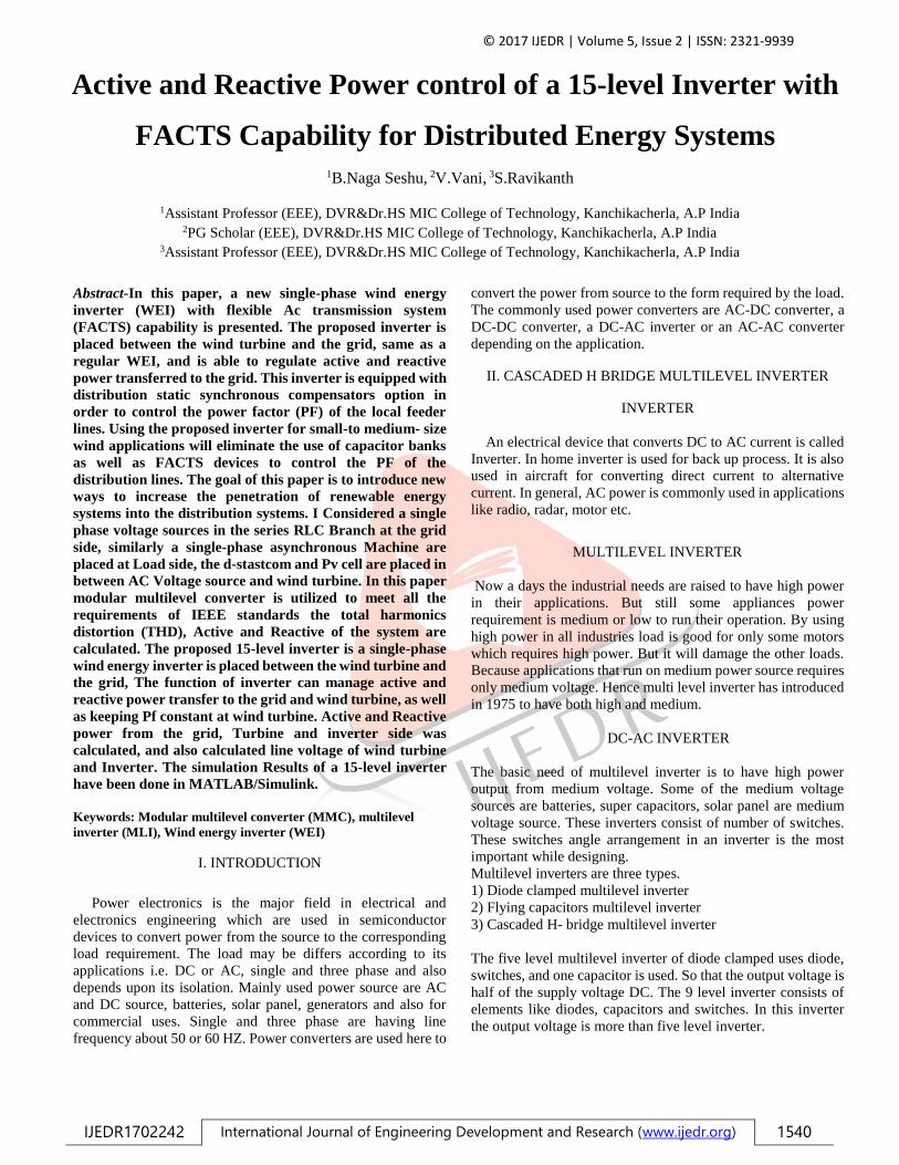
Fig 9 Simulated Active and Reactive Power of the Grid of 15-
Level Inverter
Fig 10 Power Factor of the Grid of 15-Level
Fig 11 Active and Reactive Power of the Inverter of 15-Level
Inverter
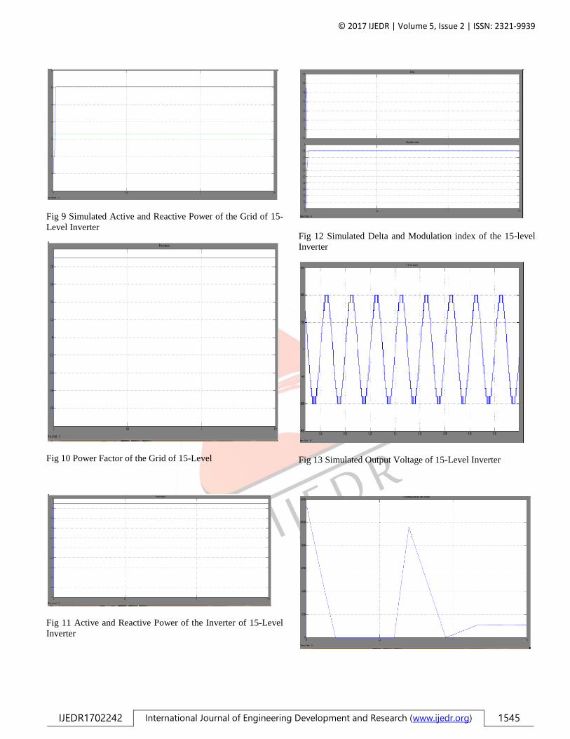
Fig 12 Simulated Delta and Modulation index of the 15-level
Inverter
Fig 13 Simulated Output Voltage of 15-Level Inverter

© 2017 IJEDR | Volume 5, Issue 2 | ISSN: 2321-9939
IJEDR1702242 International Journal of Engineering Development and Research (www.ijedr.org) 1546
Fig 14 Simulated output active power from the wind turbine of
15-Level Inverter
Fig 16 Simulated output Line Voltage of wind turbine for 15-
Level Inverter
Fig 17 Simulated output Voltage of PV-cell in 15-level Inverter
CONCLUSION
In this paper, the concept of a new multilevel inverter with
FACTS capability for small-to-mid-size wind turbine was
preferred. The proposed system demonstrates the application of
a new inverter with FACTS capability in a single unit without
any additional cost. Replacing the Asynchronous machine and
PV cell with the proposed inverter will eliminate the need of any
external STATCOM devices to regulate the PFof the grid.
Clearly, depending on the size of the compensation, multiple
inverters may be needed to reach the desired PF. This shows a
new way in which distributed renewable sources can be used to
provide control and support in distribution systems. The
proposed controller system adjusts the active power by changing
the power angle (delta) and the reactive power is controllable by
the modulation index m. The simulation results for an 15-level
inverter are presented in MATLAB/Simulink.
.
REFERENCES
[1] U.S. Solar Market Insight, 2010 Year End Review Executive
Summary, SEIA, Washington, DC, USA, 2011.
[2] AWEA U.S. Wind Industry Annual Market Report Year
Ending 2010, AWEA, Washington, DC, USA, 2011.
[3] S. A. Rahman, R. K. Varma, and W. H. Litzenberger,
“Bibliography of FACTS applications for grid integration of
wind and PV solar power systems: 1995–2010 IEEE working
group report,” in Proc. IEEE Power Energy Soc. General
Meeting, Jul. 2011, pp. 1–17.
[4] A. Beekmann, J. Marques, E. Quitmann, and S.Wachtel,
“Wind energy converters with FACTS capabilities for
optimized integration of wind power into transmission and
distribution systems,” in Proc. CIGRE/IEEE PES Joint Symp.
Integr. Wide, Scale Renew. Resour. Power Del. Syst.,
Jul. 2009, pp. 1–9.
[5] J. Rodriguez, J. S. Lai, and F. Z. Peng, “Multilevel inverters:
Survey of topologies, controls, and applications,” IEEE Trans.
Ind. Appl., vol. 49, no. 4, pp. 724–738, Aug.2002.
[6] F. Z. Peng, J. S. Lai, J. W. McKeever, and J.VanCoevering,
“A multilevel voltage-source inverter with separate DC sources
for static VAr generation,” IEEE Trans. Ind. Appl., vol. 32, no.
5, pp. 1130–1138, Oct. 1996.
[7] L. M. Tolbert and F. Z. Peng, “Multilevel converters as a
utility interface for renewable energy systems,” in Proc. IEEE
Power Eng. Soc. Summer Meeting, vol. 2. Jul. 2000, pp. 1271–
1274.
[8] S. Kouro, M. Malinowski, K. Gopakumar, J. Pou, L.
G.Franquelo, B. Wu, et al., “Recent advances and industrial
applications of multilevel converters,” IEEE Trans. Ind.
Electron., vol. 57, no. 8, pp. 2553–2580, Aug. 2010.
[9] C. Tareila, P. Sotoodeh, and R. D. Miller, “Design and
control of a single-phase D-STATCOM inverter for wind
application,” in Proc. PEMWA, Jul. 2012, pp. 1–5.
[10] B. Gultekin and M. Ermis, “Cascaded multilevel converter-
based transmission STATCOM: System design methodology
and development of a 12 kV ±12 MVAr power stage,” IEEE
Trans. Power Electron., vol. 28,
no. 11, pp. 4930–4950, Nov. 2013.
[11] R. K. Varma, S. A. Rahman, V. Sharma, and T.
Vanderheide, “Novel control of a PV solar system as
STATCOM (PV-STATCOM) for preventing instability of
induction motor load,” in Proc. 25th IEEE CCECE, May 2012,
pp. 1–5.
[12] R. Marquardt and A. Lesnicar, “New concept for high
voltage—Modular multilevel converter,” in Proc. PESC, Jun.
2004, pp. 1–5.