active aeroelastic control for helicopter rotor vibration reduction · pdf fileactive...
TRANSCRIPT
1
ACTIVE AEROELASTIC CONTROL FOR HELICOPTER ROTOR VIBRATION REDUCTION IN THE OFFSHORE ENVIRONMENT
Rodrigo Oliveira Pereira de Almeida 1, Roberto Luiz da Cunha Barroso Ramos 2
1 Universidade Federal do ABC, Santo André, Brazil, [email protected] 2 Universidade Federal do ABC, Santo André, Brazil, [email protected]
Abstract: This paper presents an analytical control design methodology for helicopter blade-sailing reduction through individual blade root control (IBRC), actuating on the blade pitch. The research is based on helicopter operations at adverse wind conditions in the offshore environment. The IBRC actuates only during rotor engagement and disengagement, which are the critical operations, when blade-sailing may be so strong that the blade can hit the helicopter fuselage. The control design is based on a linear aeroservoelastic flapping oscillator model with constant coefficients, including vertical wind gust effects. The results show that for blade root actuator limits of ±4.8º, the proposed controller can prevent blade strikes from occurring. Keywords: Blade-sailing, active aeroelastic control, individual blade root control, offshore environment.
1. INTRODUCTION
Rotating structures operating in high winds are subjected to large vibrations, which can yield several damages. Helicopter rotors, especially, when operating in the offshore environment, are in risking to be affected by a dangerous phenomenon, the blade-sailing.
The offshore environment is constituted by places out of the coast, where oil platforms and maritime bases are installed. In this environment, the occurrence of strong wind gusts is usual.
Blade-sailing is an aeroelastic phenomenon characterized by the occurrence of large flapping vibrations caused by fluid-structure interactions during engagement or disengagement operations of helicopter rotors under high wind conditions [1]. These vibrations may cause blade-fuselage impacts, usually associated with severe structural damage.
The attempt to control blade-sailing becomes even more important nowadays, once Brazil is at a growing pre-salt exploration, whose locations are in the offshore environment. With vibration control, the helicopter maintenance spending would be reduced and the operations efficiency, involving mainly transport between maritime platforms, would be increased, because the helicopters would be able to operate safely in varied meteorological conditions.
Previous research on active blade-sailing control includes swashplate-actuation for gimballed rotors [2], use of trailing-edge flaps [3], and active twist [4].
Ramos et al. [5] showed that individual blade root control, which actuates on the pitch angle, can increase the blade flapping damping, yielding significant vibration reduction. However, the relation between the constrained actuator input and the blade flapping response was not clear, due to the complexity of the adopted model.
Therefore, the present work approaches the control design, by using the blade-element theory and a representation of the forces that actuate on the blade, according to a simplified linear aeroservoelastic model, which enables an analytical blade-sailing investigation. The model properties are based on the H-46 shipboard rotor, subjected to a vertical wind gust. This helicopter has been strongly affected by blade-strike occurrences. The results, however, can be applied to any helicopter.
2. AEROSERVOELASTIC MODELING
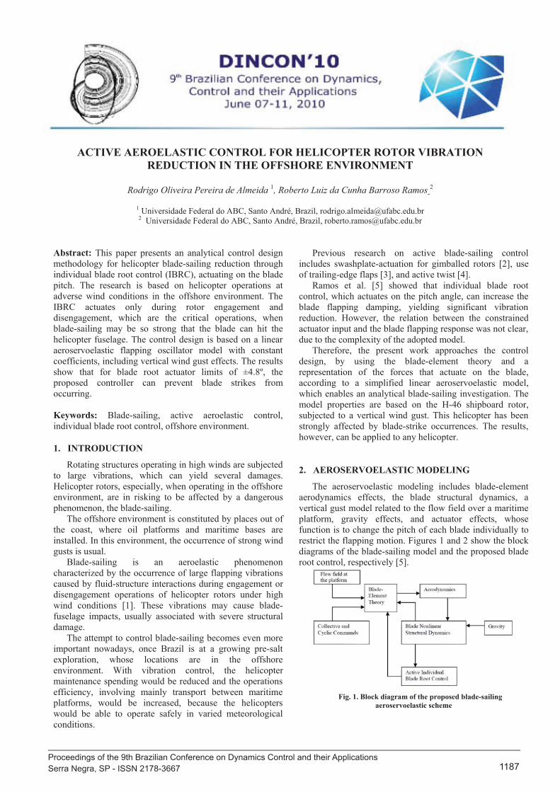
The aeroservoelastic modeling includes blade-element aerodynamics effects, the blade structural dynamics, a vertical gust model related to the flow field over a maritime platform, gravity effects, and actuator effects, whose function is to change the pitch of each blade individually to restrict the flapping motion. Figures 1 and 2 show the block diagrams of the blade-sailing model and the proposed blade root control, respectively [5].
Fig. 1. Block diagram of the proposed blade-sailing
aeroservoelastic scheme
Proceedings of the 9th Brazilian Conference on Dynamics Control and their Applications Serra Negra, SP - ISSN 2178-3667 1187

ACTIVE AEROELASTIC CONTROL FOR HELICOPTER ROTOR VIBRATION REDUCTION IN THE OFFSHORE ENVIRONMENT Rodrigo Oliveira Pereira de Almeida, Roberto Luiz da Cunha Barroso Ramos
Fig. 2. Block diagram of the proposed blade-sailing feedback
control system Figure 1 shows that aerodynamic effects due to the flow
field over the platform, collective/cyclic commands, rotor blade motions and individual blade root control input can be computed according to the blade-element theory, yielding flow velocities and an equivalent angle of attack, which determine the aerodynamic loads. From these loads and gravity effects, the blade response is obtained, and thus, the blade pitch controller can be designed. The structural nonlinearity is modeled by an approximate linear stiffness relation.
Figure 2 shows a feedback control system perspective, where the rotor blade loads due to aerodynamic effects and gravity are viewed as disturbances to the plant constituted by the blade itself and its individual root actuator. The blade control input is computed according to a flap-rate-feedback strategy and generates a compensating aerodynamic moment, whose objective is to reduce the blade vibration by increasing the flapping damping. The blade root control is individual because winds in the offshore environment vary a lot, and they are often strong, so the aerodynamic conditions on each blade may be very different.
2.1. Structural modeling
The structural modeling is done according to Figures 1 and 2, assuming some simplifications.
Considering that torsion effects are not significant for the blade-sailing modeling [6] and that the Coriolis forces are small during the low rotor rotational speed regime, only the flapping degree of freedom is taken into account. The rotor blade flapwise bending stiffness and mass are assumed uniformly distributed. The airfoil section is uniform along the blade and assumed NACA 0012. Gravity effects are considered once they are significant during the rotor engagement/disengagement operations, when the rotational speed is low.
In order to carry out the control design, the blade-sailing modeling is simplified by considering the forces and moments actuating only in the flapping plane. Figure 3 shows the forces actuating on a blade-element for this simplified model, according to a frame rotating with the blade [5].
Fig. 3. Forces at a flapping planar blade-element for the proposed
blade-sailing model
The simplified diagram of forces at a planar blade- element [7] in Figure 3 illustrates the main factors that govern the blade-sailing phenomenon. The resulting moments determine the blade tip deflections related to the angle β.
The sum of the moments actuating on the blade is given by:
BIM (1)
2B
Mdm drR
I r dm
2
0
²3
R
BM MRI r drR
3 3
3 3M R mRR
(2)
In Equation (1), represents the blade moment of
inertia about the center of rotation. In Equation (2), m represents the blade mass per unit length, R is the rotor radius. The moment due to the centrifugal force is given by:
sinc cdM dF r (3)
2 coscdF dm r (4) From (3) and (4) :
2 2 sin coscdM dmr
sincos 1
2 2 2 2
0 0
R R
cMM dmr r drR
2c BM I (5)
2
Proceedings of the 9th Brazilian Conference on Dynamics Control and their Applications Serra Negra, SP - ISSN 2178-3667 1188

In Equation (5), is the moment generated by the
centrifugal force, is the blade moment of inertia, Ω is the blade angular velocity, and β is the blade flapping angle.
The moment due to gravity is given by:
rdrRMgdmrgdM
RR
w 00
2
2wRM gm (6)
3
In Equation (6), g is the acceleration of gravity, m is the blade mass per unit length, and R is the rotor radius.
2.2. Aerodynamic modeling
From the blade-element theory and Figure 3, the moment caused by the blade lift can be determined. Figure 4 shows the flow velocity components on a blade-element [8]:
Fig. 4. Aerodynamic forces and flow velocities at a blade-element
In Figure 4, α is the angle of attack, θ is the blade pitch,
and are, respectively, the perpendicular and tangential components of the flow velocity, ϕ is approximately , dL is the lift and dD is the drag.
The blade-element lift is given by: 21dL=
2 LV dSC (7)
dS cdr 2 2² P TV U U
P ZU V r (8)
TU r (9)
In Equation (7), ρ is the air density, V is the resultant of and , dS is the blade section area and is the lift
coefficient. In Equation (8), is the wind vertical velocity over the blade, r is the distance between the root and the blade-element, and is the flapping rate.
In order to obtain a linear oscillator model with constant coefficients, the horizontal wind is assumed null, therefore, according to Equation (9), the blade-element tangential velocity is due only to the rotor rotational speed.
This simplification does not affect the blade-sailing analysis significantly, once the vertical wind component is the main responsible for the blade vibration.
According to Figure 4, it follows that: 2 2
TV U
( )L
PL tw
TU
C a a
UrC aR
(10)
In Equation (10), is the lift coefficient, a is the slope
of the lift coefficient curve, θ is the blade pitch, is the blade built-in twist, r is the distance between the root and the analyzed blade-element. From Equations (10) and (7):
21 ( )2
PT tw
TUUrdL U cdr a
R
2 (11)1 2 tw T P TU
rdL ac U U drR
The moment due to the lift over a blade-element whose distance from root is r, is given by:
2
.
12
L
tw T P TU
dM dL r
rac U U rdrR
2 2
2
12
12
L tw
Z
rdM ac r rdrR
ac V r r rdr
2 2 2
0
12
R
L tw ZrM ac r V r r rdrR
4 4
2 2
3 4
(12)
1 12 4 2 5
1 1 2 3 2 4
L t
Z
R RM ac ac
R Rac V ac
w
In Equation (12), the total lift moment over the blade is obtained. The moment due to spring effects related to the blade flapwise stiffness is given by:
(13) SM K
Proceedings of the 9th Brazilian Conference on Dynamics Control and their Applications Serra Negra, SP - ISSN 2178-3667 1189

ACTIVE AEROELASTIC CONTROL FOR HELICOPTER ROTOR VIBRATION REDUCTION IN THE OFFSHORE ENVIRONMENT Rodrigo Oliveira Pereira de Almeida, Roberto Luiz da Cunha Barroso Ramos
In Equation (13), is the spring constant and β is the flapping angle. The flapping moment in Equation (1) can be obtained from:
L c w SM M M M M (14)
where is the lift moment, is the centrifugal moment, is the weight moment, and is the spring moment. Considering that:
3
;3
3BacR mRIm
(15) where m is the blade mass per unit length, c is the blade chord and is the Lock number, Equations (5), (12) and (6) can be written as:
2c BM I
2 2
8 10
6 8
L B t
B Z B
M I
I V IR
w
(16)
32w B
gM IR
From (1), (13), (14) and (16): 2
2
2
8 8
36 2 10
B
Z tw
KI
gVR R
(17)
Considering that:
2 2, ,28nr n nr n
B
KI 2 2
where is the non-rotating flapping frequency, is the natural rotating flapping frequency, Ω is the blade angular velocity and is the damping parameter, Equation (17) can be rewritten as:
22 2
2
20 1
(18)
8 83
6 2 102 cos
nr
Z tw
n n
gVR R
A A t
In Equation (18), is the flapping acceleration, is the
flapping velocity, β is the flapping angle, is a constant term and is related to the vertical gust effects. Therefore, the approximate blade-sailing model is a linear forced harmonic oscillator.
3. INDIVIDUAL BLADE ROOT CONTROL DESIGN
The individual blade root control objective is to reduce the flapping angle variation and consequently to reduce the blade vibration to avoid an impact between the blade and the fuselage. To do that, the actuator must act in order to increase the flapping damping by varying the blade pitch. Therefore, the blade pitch feedback controller is given by:
K (19) where K is the active control parameter. Table 1 shows the parameters used for the control design:
Table 1. Parameters for the control design Parameter Value γ (Lock number) 8
(nominal rotor rotational speed) 30 rad/s Ω (engagement/disengagement rotor rotational speed)
6 rad/s
(maximum vertical wind velocity)
6 m/s
R (rotor radius) 8m (blade non-rotating flapping
frequency) 6 rad/s
(blade rotating flapping frequency)
8.5 rad/s
(blade initial pitch) 0º
(built-in twist angle) -8.5º
The vertical wind gust velocity is given by:
6cosZV t (20) The adopted wind gust frequency is the same engagement/disengagement blade natural flapping frequency, which is a condition related to large vibrations near resonance. The flapping angle is given by:
0 sins t (21)
where is a constant term related to gravity and blade twist effects, and is related to the vertical gust effects. According to Equation (18), and are determined by:
2
0 2
32 10 tw
n
gR
and
26 62
843
Zmáx Zmáx
sn
n
Zmáxs
n
V VR R
VR
Considering g=9.8 and the Table 1 values:
radrad s 12.008.00
4 Proceedings of the 9th Brazilian Conference on Dynamics Control and their Applications Serra Negra, SP - ISSN 2178-3667 1190
5
The flapping angle is obtained by substituting these values in Equation (21):
)26sin(12.008.0 t (22)
The blade hits the fuselage for the H-46 shipboard rotor if the module of β is equal or greater than 0.18 radians (10.31 degrees). So, it is clear that without the controller, there is an impact between the blade and the fuselage. Considering the proposed individual blade root control, the enhanced damping is given by:
2
2 18 8 8n K
K (23)
Considering KΩ equals to N, Equation (23) becomes:
2 18n N
From Equation (21), the flapping velocity is obtained: cosn s nt
The actuators that exist nowadays are restricted to an input of ±6º, so the controller must avoid the impact between the blade and the fuselage without exceeding these actuator limits.
máx n sK , for the controller:
4
3 (1 )Zmáx
sn
VR N
, so:
4 4 = . 3 (1 ) 3 (1 )
43 1
Zmáx Zmáxmáx n
n
Zmáxmáx
V V KKR N R NVN
N R
Substituting the values of Table 1, it results:
16 1máx
NN
(in radians)
Converting to degrees:
NNN
s
1
12.01
55.9max (24)
Equation (24) shows the relation between the blade pitch input and the blade flapping reduction. The next results show the blade pitch input and the flapping reduction for different values of N:
18.010.0020.0,958.7 ,5NFor
18.0104.0024.0,640.7 4,NFor
18.011.003.0,162.7 ,3NFor
18.012.004.0,367.6 ,2NFor
18.014.006.0,775.4 1,NFor
max0
max
max0
max
max0
max
max0
max
max0
max
s
s
s
s
s
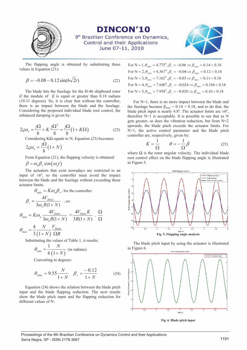
For N=1, there is no more impact between the blade and the fuselage because βmax = 0.14 < 0.18, and to do that, the blade pitch input is nearly 4.8º. The actuator limits are ±6º, therefore N=1 is acceptable. It is possible to see that as N gets greater, so does the vibration reduction, but from N=2 upwards, the blade pitch exceeds the actuator limits. For N=1, the active control parameter and the blade pitch controller are, respectively, given by:
11K (25)
where Ω is the rotor angular velocity. The individual blade root control effect on the blade flapping angle is illustrated in Figure 5.
Fig. 5. Flapping angle analysis
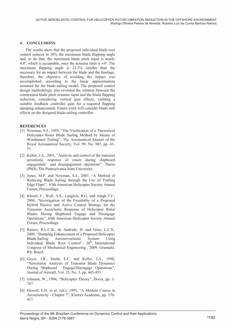
The blade pitch input by using the actuator is illustrated
in Figure 6.
Fig. 6. Blade pitch input
Proceedings of the 9th Brazilian Conference on Dynamics Control and their Applications Serra Negra, SP - ISSN 2178-3667 1191
ACTIVE AEROELASTIC CONTROL FOR HELICOPTER ROTOR VIBRATION REDUCTION IN THE OFFSHORE ENVIRONMENT Rodrigo Oliveira Pereira de Almeida, Roberto Luiz da Cunha Barroso Ramos
6
4. CONCLUSIONS
The results show that the proposed individual blade root control reduces in 30% the maximum blade flapping angle and, to do that, the maximum blade pitch input is nearly 4.8º, which is acceptable, once the actuator limit is ±6º. The maximum flapping angle is 22.2% smaller than the necessary for an impact between the blade and the fuselage, therefore, the objective of avoiding the impact was accomplished, according to the linear approximation assumed for the blade-sailing model. The proposed control design methodology also revealed the relation between the constrained blade pitch actuator input and the blade flapping reduction, considering vertical gust effects, yielding a suitable feedback controller gain for a required flapping damping enhancement. Future work will consider blade stall effects on the designed blade-sailing controller.
REFERENCES [1] Newman, S.J., 1995, “The Verification of a Theoretical
Helicopter Rotor Blade Sailing Method by Means of Windtunnel Testing”, The Aeronautical Journal of the Royal Aeronautical Society, Vol. 99, No. 982, pp. 41-51.
[2] Keller, J.A., 2001, “Analysis and control of the transient aeroelastic response of rotors during shipboard engagement and disengagement operations”, Thesis (PhD), The Pennsylvania State University.
[3] Jones, M.P. and Newman, S.J., 2007, “A Method of Reducing Blade Sailing through the Use of Trailing Edge Flaps”, 63th American Helicopter Society Annual Forum, Proceedings.
[4] Khouli, F., Wall, A.S., Langlois, R.G. and Afagh F.F., 2008, “Investigation of the Feasibility of a Proposed Hybrid Passive and Active Control Strategy for the Transient Aeroelastic Response of Helicopter Rotor Blades During Shipboard Engage and Disengage Operations”, 64th American Helicopter Society Annual Forum, Proceedings.
[5] Ramos, R.L.C.B., de Andrade, D. and Góes, L.C.S., 2009, “Damping Enhancement of a Proposed Helicopter Blade-Sailing Aeroservoelastic System Using Individual Blade Root Control”, 20th International Congress of Mechanical Engineering , 2009, Gramado, RS, Brazil.
[6] Geyer, J.R., Smith, E.C. and Keller, J.A., 1998, “Aeroelastic Analysis of Transient Blade Dynamics During Shipboard Engage/Disengage Operations”, Journal of Aircraft, Vol. 35, No. 3, pp. 445-453.
[7] Johnson, W., 1994, “Helicopter Theory”, Dover, pp. 1-767.
[8] Dowell, E.H. et al. (ed.), 1995, “A Modern Course in Aeroelasticity - Chapter 7”, Kluwer Academic, pp. 370-437.
Proceedings of the 9th Brazilian Conference on Dynamics Control and their Applications Serra Negra, SP - ISSN 2178-3667 1192