acpm750e technical reference - intellidrivesenable*, run/idle*, sync*/async inputs have on-board led...
TRANSCRIPT

Preliminary
IntelLiDrives 2000 I-DRIVE503 Technical Reference
DUAL AXIS
MICROSTEPPING DRIVER
ACPM750E
Technical Reference
Preliminary
2
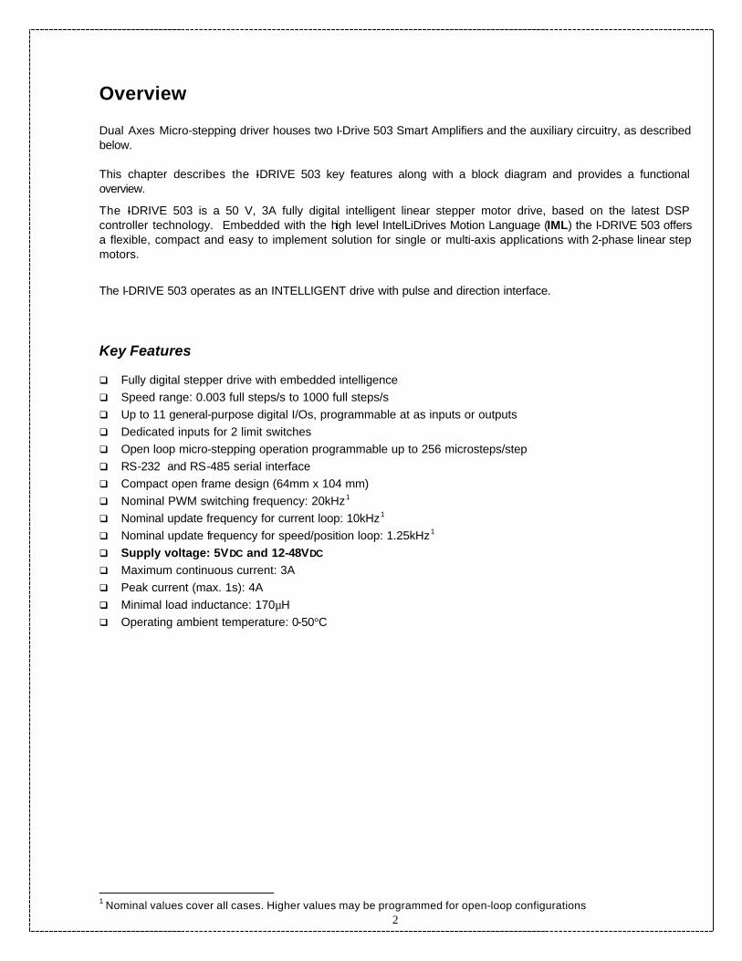
Overview Dual Axes Micro-stepping driver houses two I-Drive 503 Smart Amplifiers and the auxiliary circuitry, as described below. This chapter describes the I-DRIVE 503 key features along with a block diagram and provides a functional overview.
The I-DRIVE 503 is a 50 V, 3A fully digital intelligent linear stepper motor drive, based on the latest DSP controller technology. Embedded with the high level IntelLiDrives Motion Language (IML) the I-DRIVE 503 offers a flexible, compact and easy to implement solution for single or multi-axis applications with 2-phase linear step motors.
The I-DRIVE 503 operates as an INTELLIGENT drive with pulse and direction interface.
Key Features
q Fully digital stepper drive with embedded intelligence q Speed range: 0.003 full steps/s to 1000 full steps/s q Up to 11 general-purpose digital I/Os, programmable at as inputs or outputs q Dedicated inputs for 2 limit switches q Open loop micro-stepping operation programmable up to 256 microsteps/step q RS-232 and RS-485 serial interface q Compact open frame design (64mm x 104 mm) q Nominal PWM switching frequency: 20kHz1 q Nominal update frequency for current loop: 10kHz1 q Nominal update frequency for speed/position loop: 1.25kHz1 q Supply voltage: 5VDC and 12-48VDC q Maximum continuous current: 3A q Peak current (max. 1s): 4A q Minimal load inductance: 170µH q Operating ambient temperature: 0-50°C
1 Nominal values cover all cases. Higher values may be programmed for open-loop configurations

3
Functional Overview
Block Diagram
The block diagram of the I -DRIVE503 intelligent stepper drive In figure above, the I-DRIVE 503 control unit includes 4 control loops.
The outer loop is used for motor position control. The outer loop controller is a PID with filter on the derivative term. The PID output is used as speed command for the motor. The middle loop implements the speed control. The speed loop controller is a PI. The speed loop controller output is used as current command for the motor. The inner loop performs the current control. The inner loop uses 2 PI controllers, one for quadrature current control (Q axis controller) and the other for direct current control (D axis controller). The inner loop provides the PWM commands for the 2 H-bridges of the power stage.
The I-DRIVE 503 is configured to operate as an INTELLIGENT drive interfaced to virtually any stepping or servo motor controller/indexer through standard PULSE/DIRECTION interface. Every pulse received through PULSE input, moves motor one unit of micro-stepping resolution. The move velocity profile is determined by the user profile of the pulse stream (Trapezoidal or S-curve) received from the indexer.
E2RO
M
RAM
IntelLiSoft PROGRAM
SC CC PWM
IntelLicoder Interface (optional)
tdd
I/O Control
+ -
+ -
Auto
run
Anal
og In
puts
D
igita
l I/O
Lim
it le
ftLi
mit
right
Pos
capt
yre
Read
y
Enab
le
com
m
com
m
I-Drive 503
2 H bridges
4
Reference generator
PC
Position Controller
Speed Controller
Current Controller
Step Motor
Pulse/Dir

4
The total number of micro-steps moved is determined by the total number of pulses received from the indexer.
Interface to stepping and servo motor indexers
JP12 – Logic Power Supply Connector
Pin Name Type Function
1 GND I 0 VDC external power supply
2 +5VDC I Positive terminal of the +5VDC external power supply
JP11 – Motor Power Supply Connector
Pin Name Type Function
1 Shield I Shield /Ground
2 PGND I 0 VDC motor power supply
3 MV I +40 VDC motor power supply (fuse protected)
Note1: Both power supplies are mandatory for any working mode. For proper operation of the protection circuitry, logic power supply should be present and stable at the time of the motor power supply turn-on ORIENTATION OF THE POWER CONNECTORS (PCB components side)
CAUTION ! Caution to be observed while wiring power connections. Reversing power supply polarities and mis-wiring power and logic supplies will cause permanent damage to the drive!
all signals are TTL level
compatible, opto-isolated
INDEXER
I-DRIVE 503
PULSE
DIRECTION
COMMON
ENABLE*/DISABLE
JP12 (logic power)
JP11 (motor power)
1
1
RUN*/IDLE CURRENT
5
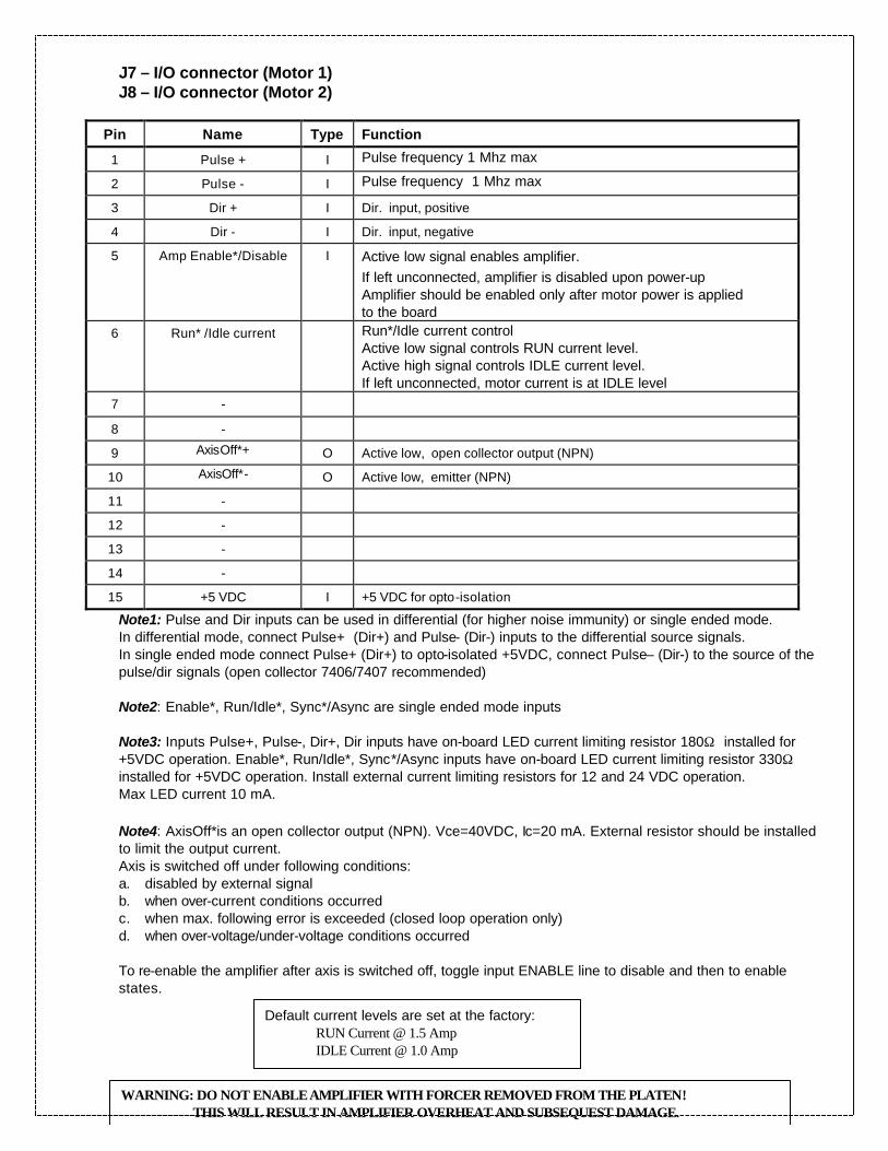
J7 – I/O connector (Motor 1) J8 – I/O connector (Motor 2)
Pin Name Type Function
1 Pulse + I Pulse frequency 1 Mhz max
2 Pulse - I Pulse frequency 1 Mhz max
3 Dir + I Dir. input, positive
4 Dir - I Dir. input, negative
5 Amp Enable*/Disable I Active low signal enables amplifier. If left unconnected, amplifier is disabled upon power-up Amplifier should be enabled only after motor power is applied to the board
6 Run* /Idle current Run*/Idle current control Active low signal controls RUN current level. Active high signal controls IDLE current level. If left unconnected, motor current is at IDLE level
7 -
8 -
9 AxisOff*+ O Active low, open collector output (NPN)
10 AxisOff*- O Active low, emitter (NPN)
11 -
12 -
13 -
14 -
15 +5 VDC I +5 VDC for opto-isolation
Note1: Pulse and Dir inputs can be used in differential (for higher noise immunity) or single ended mode. In differential mode, connect Pulse+ (Dir+) and Pulse- (Dir-) inputs to the differential source signals. In single ended mode connect Pulse+ (Dir+) to opto-isolated +5VDC, connect Pulse– (Dir-) to the source of the pulse/dir signals (open collector 7406/7407 recommended) Note2: Enable*, Run/Idle*, Sync*/Async are single ended mode inputs Note3: Inputs Pulse+, Pulse-, Dir+, Dir inputs have on-board LED current limiting resistor 180Ω installed for +5VDC operation. Enable*, Run/Idle*, Sync*/Async inputs have on-board LED current limiting resistor 330Ω installed for +5VDC operation. Install external current limiting resistors for 12 and 24 VDC operation. Max LED current 10 mA. Note4: AxisOff*is an open collector output (NPN). Vce=40VDC, Ic=20 mA. External resistor should be installed to limit the output current. Axis is switched off under following conditions: a. disabled by external signal b. when over-current conditions occurred c. when max. following error is exceeded (closed loop operation only) d. when over-voltage/under-voltage conditions occurred To re-enable the amplifier after axis is switched off, toggle input ENABLE line to disable and then to enable states.
Default current levels are set at the factory: RUN Current @ 1.5 Amp IDLE Current @ 1.0 Amp
WARNING: DO NOT ENABLE AMPLIFIER WITH FORCER REMOVED FROM THE PLATEN! THIS WILL RESULT IN AMPLIFIER OVERHEAT AND SUBSEQUEST DAMAGE.

6

7
J5 – Motor 1 connector J6 – Motor 2 connector
Pin Name Type Function
1 A+ I motor phase A+
2
3 B- I motor phase B-
4
5
6
7 A- I motor phase A-
8
9 B+ I motor phase B+
J1 – Encoder 1 input connector (to/from encoder) J3 – Encoder 2 input connector (to/from encoder)
Pin Name Type Function
1 A- I encoder A+
2 GND O ground (power supply for the encoder)
3 B- I encoder B-
4 SHIELD I shield
5 R- I encoder Index-
6 A+ I encoder A+
7 +5VDC O +5VDC (power supply for the encoder)
8 B+ I encoder B+
9 R+ I encoder Index +
Note1: Encoder signals are differential, TTL level compatible J2 – Encoder 1 output connector (to display or supervisory controller) J4 – Encoder 2 output connector (to display or supervisory controller)

8
Pin Name Type Function
1 A- O encoder A+
2 GND ground
3 B- O encoder B-
4 SHIELD shield
5 R- O encoder Index-
6 A+ O encoder A+
7 - - -
8 B+ O encoder B+
9 R+ O encoder Index +
Note1: Encoder signals are differential, TTL level compatible
Connectors Type and Mating Connectors
Connector Function Gender Connector
Mating connector
JP12 Logic Power supply 2 CT PCB pin header Digikey part #A1448-ND
2 CT plug Digikey part #A1448-ND
with sockets part # A1437-ND
Amp part # 1-480698-0
socket #350689-1 JP11 Motor Power supply 3 CT PCB pin header
Digikey part #A1468-ND
2 CT plug Digikey part #A1450-ND
with sockets part # A1437-ND
Amp par # 1-480700-0
socket #350689-1 J5, J6 Motor connector M DB9M, Digikey part # 509M-ND DB9F, Digikey part # 509F-ND J7, J8 IO M DB15M, Digikey part # 515M-ND DB15F, Digikey part # 515F-ND J1, J3 Encoder F DB9F, Digikey part # 509F-ND DB9M, Digikey part # 509M-ND J2, J4 Display M DB9M, Digikey part # 509M-ND DB9F, Digikey part # 509F-ND
Recommended power supplies: Logic supply +5VDC, IntelLiDrives pn# DTS050250SUDC-P5P (110VAC/5VDC-1.5Amp)
Motor power supply +40VDC, IntelLiDrives pn# ISP300-4 (110VAC/40VDC-3 Amp)
Fuses 3.0A (fast blow) or 2.5A (slow blow) F1 - motor1 F2 – motor2 LEDs D22 – logic power OK (green) D5, D6 – motor power OK (green)

9
D1, D2 – amp off (red) D3, D4 – future use (green) TEST POINTS All signals are TTL level, referenced logic supply ground. TP1 (TP11) - Pulse stream from the indexer TP2 (TP12) - Direction signal from the indexer TP3 (TP13) - ServoOff* signal received from the indexer TP8 (TP18) – Encoder B TP9 (TP19) – Encoder B TP20 - +5VDC TP24 - Motor ground TP21 – Logic ground

Preliminary
IntelLiDrives 2000 I-DRIVE503 Technical Reference
board width 7” board height 8”
Logic power supply connector
Motor power supply connector
Axis1 IO connector
Axis2 IO connector
Motor1 connector
Encoder1 connector
Motor2 connector
Encoder2 connector