aco construction & building products - grating · pdf fileaco construction & building...
TRANSCRIPT

ACO Construction & Building Products
Technical Handbook and Product Catalog
ACO DRAIN
Product Selection Guidelines
Product Details
Technical Design Support
Commercia l Trench Drains
www.acousa.com
2
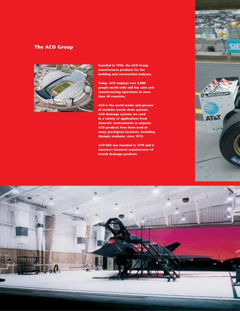
The ACO Group
Founded in 1946, the ACO Group
manufactures products for the
building and construction industry.
Today, ACO employs over 3,800
people world-wide and has sales and
manufacturing operations in more
than 40 countries.
ACO is the world leader and pioneer
of modular trench drain systems.
ACO drainage systems are used
in a variety of applications from
domestic environments to airports.
ACO products have been used at
many prestigious locations, including
Olympic stadiums, since 1972.
ACO USA was founded in 1978 and is
America’s foremost manufacturer of
trench drainage products.
ACO DRAIN
www.acousa.com
3
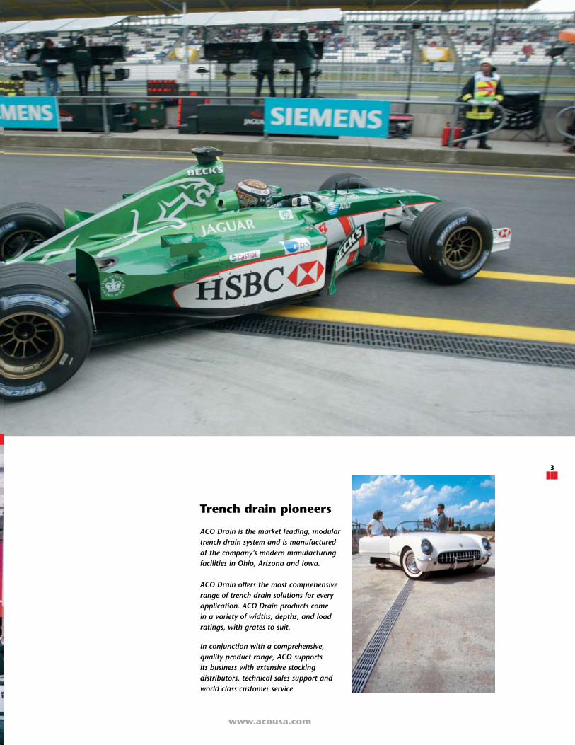
Trench drain pioneers
ACO Drain is the market leading, modulartrench drain system and is manufacturedat the company’s modern manufacturingfacilities in Ohio, Arizona and Iowa.
ACO Drain offers the most comprehensiverange of trench drain solutions for everyapplication. ACO Drain products comein a variety of widths, depths, and loadratings, with grates to suit.
In conjunction with a comprehensive,quality product range, ACO supportsits business with extensive stockingdistributors, technical sales support andworld class customer service.
www.acousa.com
4
Surface Drainage
6 Surface drainage options
8 Product selection
10 Trench drain hydraulics
16 Loadings
22 Material data
24 End user requirements
Standard Products
26 KlassikDrain - K100S, KS100S
40 PowerDrain - S100K, S300K
52 Polymer concrete catch basins
54 Accessories
56 FlowDrain - FG100, FG200
70 FastForm - FF300, FF600
Problem Solving Products
78 SlabDrain - H80, H100, H80K, H100K, H100SK
84 ChemDrain - C100, CK100S, CS100K, CH80, CH100, CH80K, CH100K, CH100SK
100 Brickslot
102 Membrane Drain
104 MiniKlassik
106 Cross Sidewalk Drain (CSD)
Technical Support and Other Information
110 Trench hydraulics service
111 Grate hydraulics service
112 Layout & scheduling service
114 Ponding analysis
115 Chemical resistance
116 Construction and installation
120 Installation diagrams
122 Volumetric channel capacities
123 Glossary & part number listing
Contents
4
ACO DRAIN
www.acousa.com
5
www.acousa.com
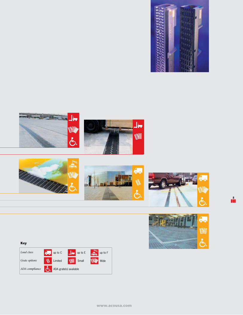
Key
up to C up to E up to F
Limited Small
ADA grate(s) available
Load class
ADA compliance
Grate options Wide
5
www.acousa.com
6
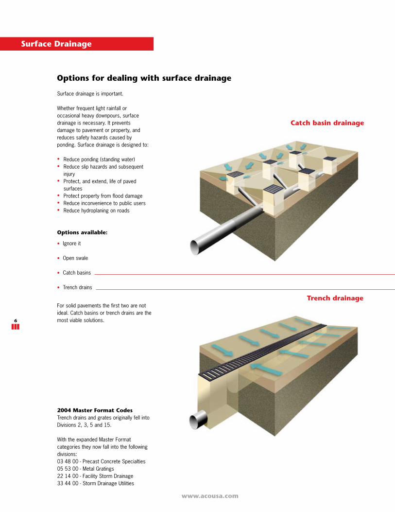
Options for dealing with surface drainage
Surface drainage is important.
Whether frequent light rainfall oroccasional heavy downpours, surfacedrainage is necessary. It preventsdamage to pavement or property, andreduces safety hazards caused byponding. Surface drainage is designed to:
• Reduce ponding (standing water)• Reduce slip hazards and subsequent injury• Protect, and extend, life of paved surfaces• Protect property from flood damage• Reduce inconvenience to public users• Reduce hydroplaning on roads
Options available:
• Ignore it
• Open swale
• Catch basins
• Trench drains
For solid pavements the first two are notideal. Catch basins or trench drains are themost viable solutions.
Trench drainage
Catch basin drainage
2004 Master Format CodesTrench drains and grates originally fell intoDivisions 2, 3, 5 and 15.
With the expanded Master Formatcategories they now fall into the followingdivisions:03 48 00 - Precast Concrete Specialties05 53 00 - Metal Gratings22 14 00 - Facility Storm Drainage33 44 00 - Storm Drainage Utilities
Surface Drainage

ACO DRAIN
www.acousa.com
7
• Uneven, undulating appearance• Complex, multiple grades to design and
construct• Deeper ground excavation due to pipe
depths• Higher risk of ponding• Pipes prone to blocking and failure• Maintenance can be difficult and costly
as access to pipe work is restricted• Possible interference with other
services, e.g., electrical, sewage, etc.
• Neat linear appearance• Simple grades to design and construct• Easy to install - shallower excavation and
easy grading of pavement• Continuously intercepts water and
provides superior drainage• Minimal underground pipes - less
excavation and site disturbance• Maintenance is quick and easy as trench
is at the surface and easier to access
Sustainable drainage
Sustainable drainage is an element of the‘Hydrological Cycle’. It is the collection ofrainwater, its treatment and, ultimately, itsreuse.
The process involves capturing waterrun-off, that may or may not containpollutants, so it can be dealt with in acontrolled manner. The water can thenbe treated, stored for future use, ortransported to receiving waterways. Thistransfer of water should come at low cost,and cause minimal damage and danger tothe environment.
Surface drainage can be used whererainwater has collected on paved areas forthe ‘capture’ part of this process.
Trench drains are ideal for the capture andcollection of storm water run-off. They forma barrier to prevent rainwater run-off flowingonto the soft landscaping where collectionis more difficult. This is of particularimportance if the risk of contaminationis high, such as highway and gas stationapplications.
ACO provides a wide range of trenchdrains to meet the hydraulic needs of anysustainable drainage design.
LEED
'Leadership in Energy and EnvironmentalDesign'; provides a green building ratingsystem. Principles have been applied tocommercial and institutional projects,schools, multi-unit residential buildings,manufacturing plants, laboratories and otherbuilding types.
Areas where the use of trench drainage mayassist in the assignment of credits include:
SUSTAINABLE SITESCredit 5.1 - Site DevelopmentCompared to catch basins, trench drainsrequire minimal excavation; reducing sitedisruption.6.1 & 6.2 - Stormwater DesignTrench drains capture run-off, enablingtreatment which prevents pollution of receivingstreams. Run-off can also be collected for non-potable uses such as irrigation.
WATER EFFICIENCYCredit 1.1 & 1.2 Water EfficientLandscapingReduce or eliminate use of potable water forirrigation by capturing rainwater in trenchdrains and storing for future irrigation use.Credit 2 - Innovative WastewaterTechnologiesUsing captured rainwater for buildingsewage conveyance.Credit 3.1 & 3.2 - Water Use ReductionCapturing and re-using stormwater for non-potable applications.
MATERIALS & RESOURCESCredit 2.1 & 2.2 - Construction WasteManagement. Reduction of debris goingto landfills and incinerators. Compared toarea drains, trench drains require minimalexcavation; reducing site waste/debris.
Compared to polystyrene formers, FastFormcardboard formers are easier to dispose of.
Go to www.usgbc.org for full details.
www.acousa.com
8
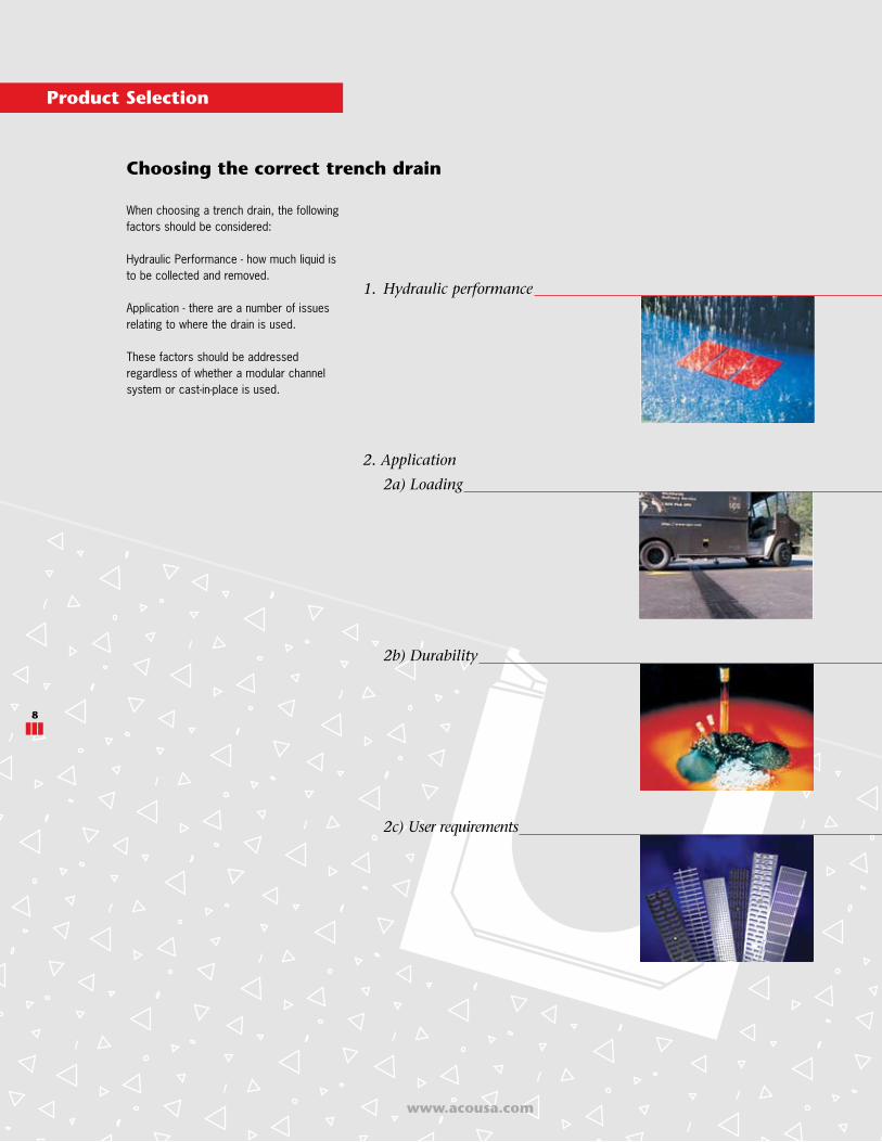
1. Hydraulic performance
2. Application
2a) Loading
2b) Durability
2c) User requirements
www.acousa.com
When choosing a trench drain, the followingfactors should be considered:
Hydraulic Performance - how much liquid isto be collected and removed.
Application - there are a number of issuesrelating to where the drain is used.
These factors should be addressedregardless of whether a modular channelsystem or cast-in-place is used.
Choosing the correct trench drain
Product Selection
8
ACO DRAIN
www.acousa.com
9
www.acousa.com
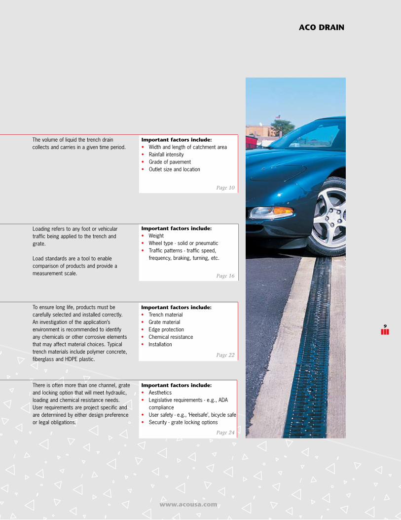
Loading refers to any foot or vehiculartraffic being applied to the trench andgrate.
Load standards are a tool to enablecomparison of products and provide ameasurement scale.
The volume of liquid the trench draincollects and carries in a given time period.
Important factors include:• Width and length of catchment area• Rainfall intensity• Grade of pavement• Outlet size and location
Important factors include:• Weight• Wheel type - solid or pneumatic• Traffic patterns - traffic speed,
frequency, braking, turning, etc.
There is often more than one channel, grateand locking option that will meet hydraulic,loading and chemical resistance needs.User requirements are project specific andare determined by either design preferenceor legal obligations.
Page 10
Page 16
Important factors include:• Trench material• Grate material• Edge protection• Chemical resistance• Installation
Page 22
To ensure long life, products must becarefully selected and installed correctly.An investigation of the application’senvironment is recommended to identifyany chemicals or other corrosive elementsthat may affect material choices. Typicaltrench materials include polymer concrete,fiberglass and HDPE plastic.
Important factors include:• Aesthetics• Legislative requirements - e.g., ADA
compliance• User safety - e.g., ‘Heelsafe’, bicycle safe• Security - grate locking options
Page 24
ACO DRAIN
9
www.acousa.com
10
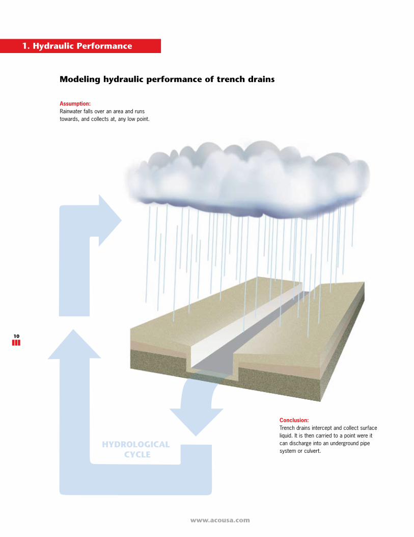
Modeling hydraulic performance of trench drains
Assumption:Rainwater falls over an area and runstowards, and collects at, any low point.
1. Hydraulic Performance
HYDROLOGICALCYCLE
Conclusion:Trench drains intercept and collect surfaceliquid. It is then carried to a point were itcan discharge into an underground pipesystem or culvert.
ACO DRAIN
www.acousa.com
11
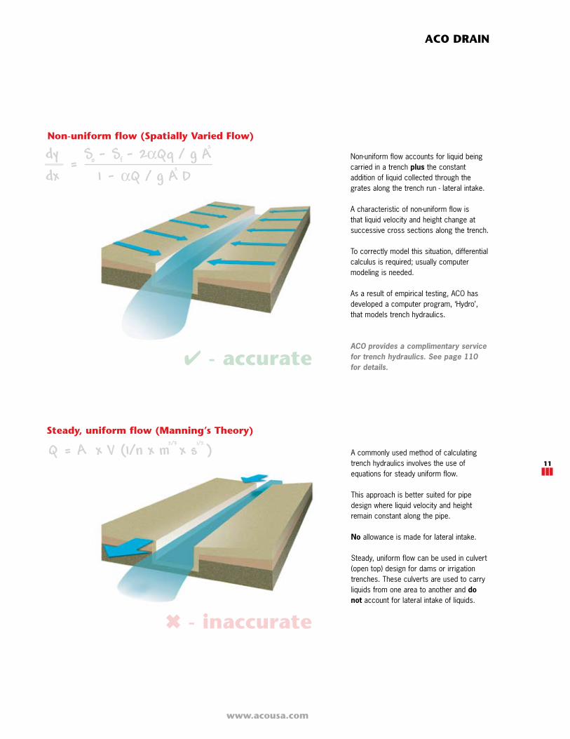
Non-uniform flow accounts for liquid beingcarried in a trench plus the constantaddition of liquid collected through thegrates along the trench run - lateral intake.
A characteristic of non-uniform flow isthat liquid velocity and height change atsuccessive cross sections along the trench.
To correctly model this situation, differentialcalculus is required; usually computermodeling is needed.
As a result of empirical testing, ACO hasdeveloped a computer program, ‘Hydro’,that models trench hydraulics.
ACO provides a complimentary service for trench hydraulics. See page 110 for details.
A commonly used method of calculatingtrench hydraulics involves the use ofequations for steady uniform flow.
This approach is better suited for pipedesign where liquid velocity and heightremain constant along the pipe.
No allowance is made for lateral intake.
Steady, uniform flow can be used in culvert(open top) design for dams or irrigationtrenches. These culverts are used to carryliquids from one area to another and donot account for lateral intake of liquids.
- accurate
Non-uniform flow (Spatially Varied Flow)
Steady, uniform flow (Manning’s Theory)
- inaccurate
www.acousa.com
12
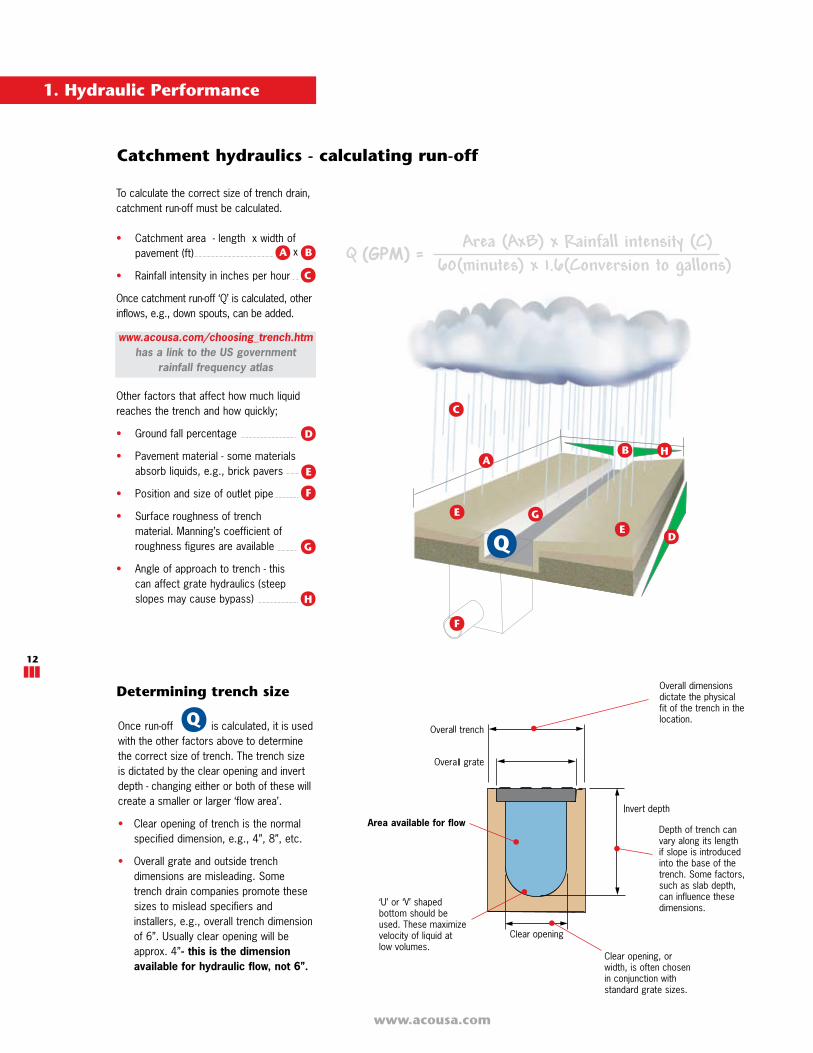
To calculate the correct size of trench drain, catchment run-off must be calculated.
• Catchment area - length x width ofpavement (ft)
• Rainfall intensity in inches per hour
Once catchment run-off ‘Q’ is calculated, otherinflows, e.g., down spouts, can be added.
Other factors that affect how much liquidreaches the trench and how quickly;
• Ground fall percentage
• Pavement material - some materialsabsorb liquids, e.g., brick pavers
• Position and size of outlet pipe
• Surface roughness of trenchmaterial. Manning’s coefficient ofroughness figures are available
• Angle of approach to trench - thiscan affect grate hydraulics (steepslopes may cause bypass)
Once run-off is calculated, it is usedwith the other factors above to determinethe correct size of trench. The trench sizeis dictated by the clear opening and invertdepth - changing either or both of these willcreate a smaller or larger ‘flow area’.
• Clear opening of trench is the normal specified dimension, e.g., 4”, 8”, etc.
• Overall grate and outside trench dimensions are misleading. Some trench drain companies promote these sizes to mislead specifiers and installers, e.g., overall trench dimension of 6”. Usually clear opening will be approx. 4”- this is the dimension available for hydraulic flow, not 6”.
Q
Catchment hydraulics - calculating run-off
Clear opening, orwidth, is often chosenin conjunction withstandard grate sizes.
Depth of trench canvary along its lengthif slope is introducedinto the base of thetrench. Some factors,such as slab depth,can influence thesedimensions.
Overall dimensionsdictate the physicalfit of the trench in thelocation.
‘U’ or ‘V’ shapedbottom should beused. These maximizevelocity of liquid atlow volumes.
BxA
C
D
E
F
G
H
A
C
DE
F
G
HB
E
Determining trench size
www.acousa.com/choosing_trench.htm has a link to the US government
rainfall frequency atlas
Area available for flow
1. Hydraulic Performance

ACO DRAIN
www.acousa.com
13
Ground fall or slopeD
Factors affecting trench run hydraulics
Slope is part of the equation - but not as amultiplier. Trench size is accurately calculated.
When slope is large, velocity is also calculatedas high. Trench size is under sized - resulting inflooding.
Effect of slope on trench hydraulic performance
Slope increases the velocity of liquid withinthe trench drain and improves hydraulicefficiency. Slope can be introduced by:
1. Existing pavement with natural fall.
2. Introducing slope along the base of thetrench run.
3. Combination of both.
4. Negative fall.
2.
3.
Steady uniform flowUses Area x Velocity to estimate flow capacity. When there is little or minimal slope,velocity tends towards zero, and trench performance is under estimated.
When there is significant slope, steady uniform flow over estimates the hydraulicperformance of the trench drain.
1.
Neutral invert, zero ground fall
Neutral invert, positive ground fall
Sloped invert, positive ground fall
Sloped invert, zero ground fall
Zero slope
Small slope
Large slope
Slope is part of the equation - but not as amultiplier. Trench size is accurately calculated.
Slope is a multiplier in the equation ( Q=A x (1/nx m² ³ x s½). Velocity is calculated as zero andtrench size cannot be calculated.
Slope is part of the equation - but not as amultiplier. Trench size is accurately calculated.
When slope is small, velocity is calculated asminimal. Trench size is over sized - resulting ina larger, more costly trench.
Non-uniform flow Accurately accounts for affect of slope andrun length. Models the accurate hydraulicperformance of trench. Allows correct sizeof trench drain to be used.
Zero slope
Small slope
Large slope
www.acousa.com
14
Factors affecting trench run hydraulics
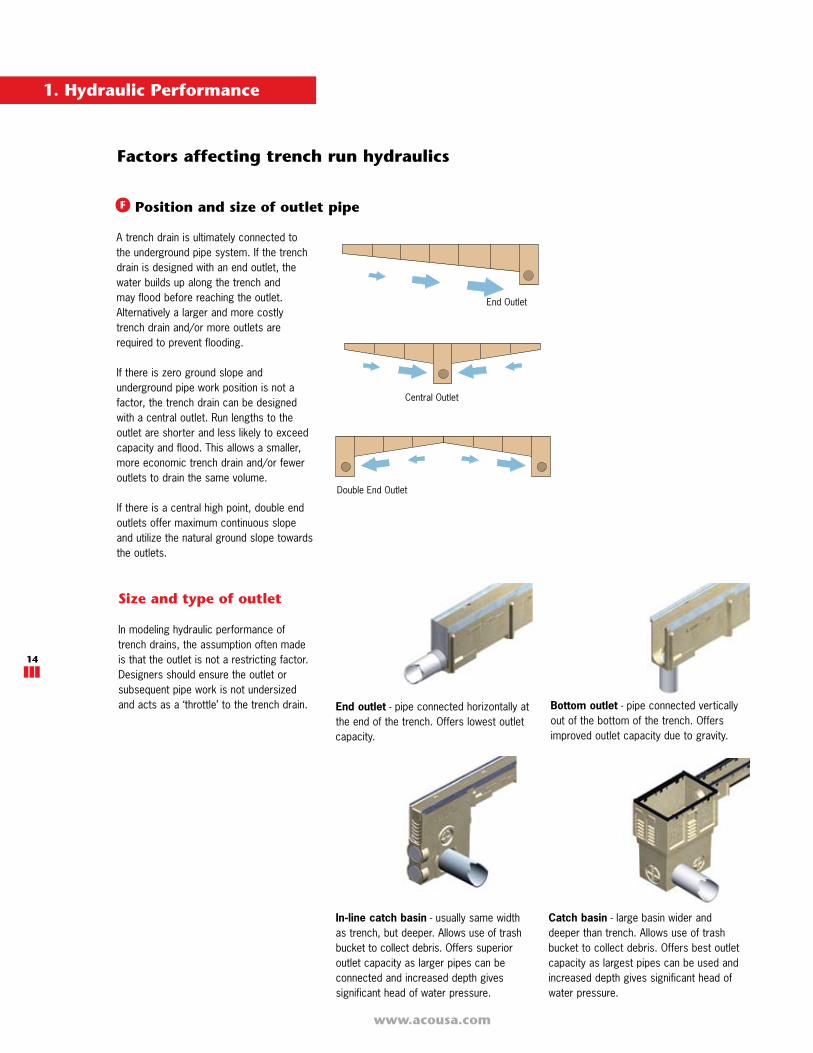
A trench drain is ultimately connected tothe underground pipe system. If the trenchdrain is designed with an end outlet, thewater builds up along the trench andmay flood before reaching the outlet.Alternatively a larger and more costlytrench drain and/or more outlets arerequired to prevent flooding.
If there is zero ground slope andunderground pipe work position is not afactor, the trench drain can be designedwith a central outlet. Run lengths to theoutlet are shorter and less likely to exceedcapacity and flood. This allows a smaller,more economic trench drain and/or feweroutlets to drain the same volume.
If there is a central high point, double endoutlets offer maximum continuous slopeand utilize the natural ground slope towardsthe outlets.
End Outlet
Central Outlet
Position and size of outlet pipe
Size and type of outlet
In modeling hydraulic performance oftrench drains, the assumption often madeis that the outlet is not a restricting factor.Designers should ensure the outlet orsubsequent pipe work is not undersizedand acts as a ‘throttle’ to the trench drain.
In-line catch basin - usually same widthas trench, but deeper. Allows use of trashbucket to collect debris. Offers superioroutlet capacity as larger pipes can beconnected and increased depth givessignificant head of water pressure.
Bottom outlet - pipe connected verticallyout of the bottom of the trench. Offersimproved outlet capacity due to gravity.
Catch basin - large basin wider anddeeper than trench. Allows use of trashbucket to collect debris. Offers best outletcapacity as largest pipes can be used andincreased depth gives significant head ofwater pressure.
End outlet - pipe connected horizontally atthe end of the trench. Offers lowest outletcapacity.
F
Double End Outlet
1. Hydraulic Performance

ACO DRAIN
www.acousa.com
15
2. Clear opening
Lateral inflow from surrounding pavement
100% CaptureAll liquid flowing through grate
Less than 100% CaptureNot all liquid flowing through grate, bypass hasoccurred. Could be due to not enough grateopen area, too much liquid, or too much slopeperpendicular to grate
BypassGrate hydraulics
Usually the trench drain reaches hydrauliccapacity before grate intake hydraulicsaffect performance. Occasionally gratehydraulics become the determining factor,especially with restricted openings, e.g.,perforated grates.
To calculate grate hydraulics, the followinginformation is required;
• Trench length• Width of catchment area each side of
trench• Pavement type• Geometry of catchment area including
slope approaching the grate
Angle of approach to trenchG
Hydraulic summary
Key factors to consider:
ACO provides a complimentary service for grate intake hydraulics. See page 111 for details.
Area available
for flow
3. Slope 4. Outlet
Neutral invert no ground fall
Sloped invert no ground fall
See page 12See page 11
See page 13 See page 14
1. Lateral intake
www.acousa.com
16
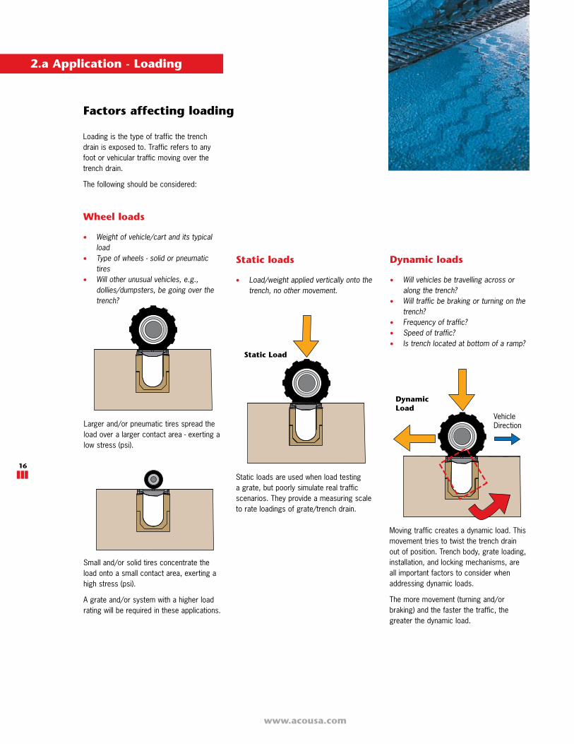
Factors affecting loading
VehicleDirection
Small and/or solid tires concentrate theload onto a small contact area, exerting ahigh stress (psi).
A grate and/or system with a higher loadrating will be required in these applications.
Larger and/or pneumatic tires spread theload over a larger contact area - exerting alow stress (psi).
Moving traffic creates a dynamic load. Thismovement tries to twist the trench drainout of position. Trench body, grate loading,installation, and locking mechanisms, areall important factors to consider whenaddressing dynamic loads.
The more movement (turning and/orbraking) and the faster the traffic, thegreater the dynamic load.
Static loads are used when load testinga grate, but poorly simulate real trafficscenarios. They provide a measuring scaleto rate loadings of grate/trench drain.
Static loads
• Load/weight applied vertically onto the trench, no other movement.
Static Load
DynamicLoad
Dynamic loads
• Will vehicles be travelling across or along the trench?
• Will traffic be braking or turning on the trench?
• Frequency of traffic?• Speed of traffic?• Is trench located at bottom of a ramp?
Loading is the type of traffic the trenchdrain is exposed to. Traffic refers to anyfoot or vehicular traffic moving over thetrench drain.
The following should be considered:
Wheel loads
• Weight of vehicle/cart and its typical load
• Type of wheels - solid or pneumatic tires
• Will other unusual vehicles, e.g., dollies/dumpsters, be going over the trench?
2.a Application - Loading
ACO DRAIN
www.acousa.com
17
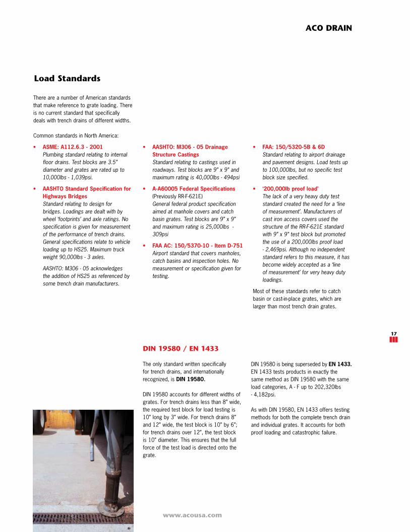
DIN 19580 / EN 1433
The only standard written specificallyfor trench drains, and internationallyrecognized, is DIN 19580.
DIN 19580 accounts for different widths ofgrates. For trench drains less than 8” wide,the required test block for load testing is10” long by 3” wide. For trench drains 8”and 12” wide, the test block is 10” by 6”; for trench drains over 12”, the test blockis 10” diameter. This ensures that the fullforce of the test load is directed onto thegrate.
Load Standards
There are a number of American standardsthat make reference to grate loading. Thereis no current standard that specificallydeals with trench drains of different widths.
Common standards in North America:
• ASME: A112.6.3 - 2001Plumbing standard relating to internal floor drains. Test blocks are 3.5” diameter and grates are rated up to 10,000lbs - 1,039psi.
• AASHTO Standard Specification forHighways Bridges Standard relating to design for bridges. Loadings are dealt with by wheel ‘footprints’ and axle ratings. No specification is given for measurement of the performance of trench drains. General specifications relate to vehicle loading up to HS25. Maximum truck weight 90,000lbs - 3 axles.
AASHTO: M306 - 05 acknowledges the addition of HS25 as referenced by some trench drain manufacturers.
• AASHTO: M306 - 05 DrainageStructure Castings Standard relating to castings used in roadways. Test blocks are 9” x 9” and maximum rating is 40,000lbs - 494psi
• A-A60005 Federal Specifications(Previously RR-F-621E) General federal product specification aimed at manhole covers and catch basin grates. Test blocks are 9” x 9” and maximum rating is 25,000lbs - 309psi
• FAA AC: 150/5370-10 - Item D-751Airport standard that covers manholes, catch basins and inspection holes. No measurement or specification given for testing.
• FAA: 150/5320-5B & 6D Standard relating to airport drainage and pavement designs. Load tests up to 100,000lbs, but no specific test block size specified.
• ‘200,000lb proof load’ The lack of a very heavy duty test standard created the need for a ‘line of measurement’. Manufacturers of cast iron access covers used the structure of the RR-F-621E standard with 9” x 9” test block but promoted the use of a 200,000lbs proof load - 2,469psi. Although no independent standard refers to this measure, it has become widely accepted as a ‘line of measurement’ for very heavy duty loadings.
Most of these standards refer to catchbasin or cast-in-place grates, which arelarger than most trench drain grates.
DIN 19580 is being superseded by EN 1433.EN 1433 tests products in exactly thesame method as DIN 19580 with the sameload categories, A - F up to 202,320lbs- 4,182psi.
As with DIN 19580, EN 1433 offers testingmethods for both the complete trench drainand individual grates. It accounts for bothproof loading and catastrophic failure.
www.acousa.com
18
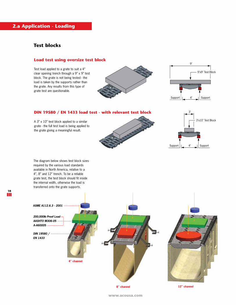
A 3” x 10” test block applied to a similargrate - the full test load is being applied tothe grate giving a meaningful result.
DIN 19580 / EN 1433 load test - with relevant test block
Test load applied to a grate to suit a 4”clear opening trench through a 9” x 9” testblock. The grate is not being tested - theload is taken by the supports rather thanthe grate. Any results from this type ofgrate test are questionable.
Load test using oversize test block
Test blocks
The diagram below shows test block sizesrequired by the various load standardsavailable in North America, relative to a4”, 8” and 12” trench. To be a reliablegrate test, the test block should fit insidethe internal width, otherwise the load istransferred onto the grate supports.
2.a Application - Loading
DIN 19580 / EN 1433
ASME A112.6.3 - 2001
200,000lb Proof LoadAASHTO M306-05A-A60005
4" channel
8" channel 12" channel
ACO DRAIN
www.acousa.com
19
308psi
494psi
1,039psi
2,469psi
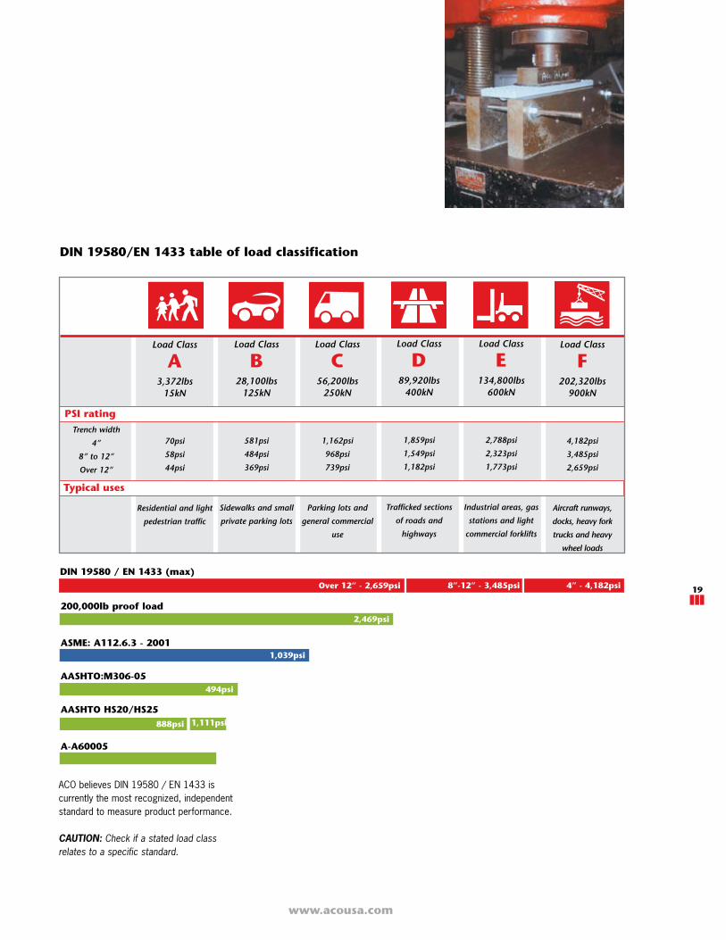
ACO believes DIN 19580 / EN 1433 iscurrently the most recognized, independentstandard to measure product performance.
CAUTION: Check if a stated load class relates to a specific standard.
Load Class
A3,372lbs
15kN
70psi
58psi
44psi
Residential and light
pedestrian traffic
Load Class
B28,100lbs
125kN
581psi
484psi
369psi
Sidewalks and small
private parking lots
Load Class
C56,200lbs
250kN
1,162psi
968psi
739psi
Parking lots and
general commercial
use
Load Class
D89,920lbs
400kN
1,859psi
1,549psi
1,182psi
Trafficked sections
of roads and
highways
Load Class
E134,800lbs
600kN
2,788psi
2,323psi
1,773psi
Industrial areas, gas
stations and light
commercial forklifts
Load Class
F202,320lbs
900kN
4,182psi
3,485psi
2,659psi
Aircraft runways,
docks, heavy fork
trucks and heavy
wheel loads
Trench width
4”
8” to 12”
Over 12”
Typical uses
Over 12” - 2,659psi
PSI rating
DIN 19580 / EN 1433 (max)
200,000lb proof load
ASME: A112.6.3 - 2001
AASHTO:M306-05
A-A60005
DIN 19580/EN 1433 table of load classification
8”-12” - 3,485psi 4” - 4,182psi
1,111psi
AASHTO HS20/HS25888psi
www.acousa.com
20
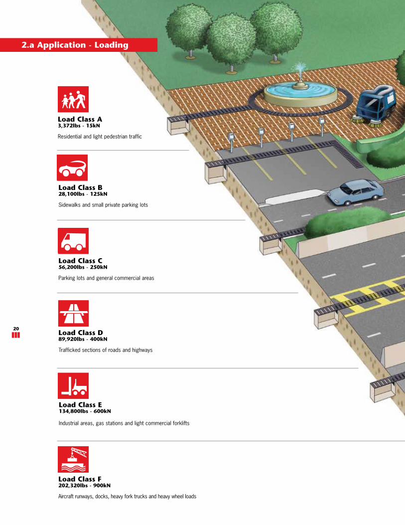
Load Class A3,372lbs - 15kN
Residential and light pedestrian traffic
Load Class B28,100lbs - 125kN
Sidewalks and small private parking lots
Load Class C56,200lbs - 250kN
Parking lots and general commercial areas
Load Class D89,920lbs - 400kN
Trafficked sections of roads and highways
Load Class E134,800lbs - 600kN
Industrial areas, gas stations and light commercial forklifts
Load Class F202,320lbs - 900kN
Aircraft runways, docks, heavy fork trucks and heavy wheel loads
2.a Application - Loading

ACO DRAIN
www.acousa.com
21
www.acousa.com
22
Modular trench drain systems are generallymanufactured from either polymerconcrete, fiberglass or HDPE (High DensityPolyethylene).
ACO Drain commercial grade trenchsystems are manufactured from eitherpolymer concrete or fiberglass. Othermaterials do not meet the compressivestrength and thermal expansion propertiesrequired in commercial and industrialprojects.
ACO only uses HDPE as a trench materialfor residential applications.
Fiberglass
Fiberglass uses similar resin binding agentsto those used for polymer concrete, butglass mat and fibers are used instead ofmineral aggregates to provide a robustflexible material.
Fiberglass trench drains are designed to befully encased in concrete.
Cement concrete
Cement concrete is Portland cement mixedwith aggregates. Generally used for largecast-in-place slab applications, where massis required for structural rigidity.
HDPE (Plastic)
High Density Polyethylene (HDPE) is themost common plastic used in trenchdrains. HDPE is a readily available,economical material that is easy to mold.HDPE has poor thermal properties. Atrench drain of 100ft in length with anambient temperature change of 75°F canexpand (or contract) up to 9.9 inchesmore than the surrounding concrete slab.The concrete surround will only changeminimally and cause the trench to buckle orpull away from the concrete.
Grates
Grates are manufactured from a variety ofmaterials. The most common are ductileiron, mild steel, stainless steel and plastic.
Grates need better tensile properties thanthe trench body to withstand flexural loads.Grates can be changed or easily replacedafter installation, unlike the trench drainbody.
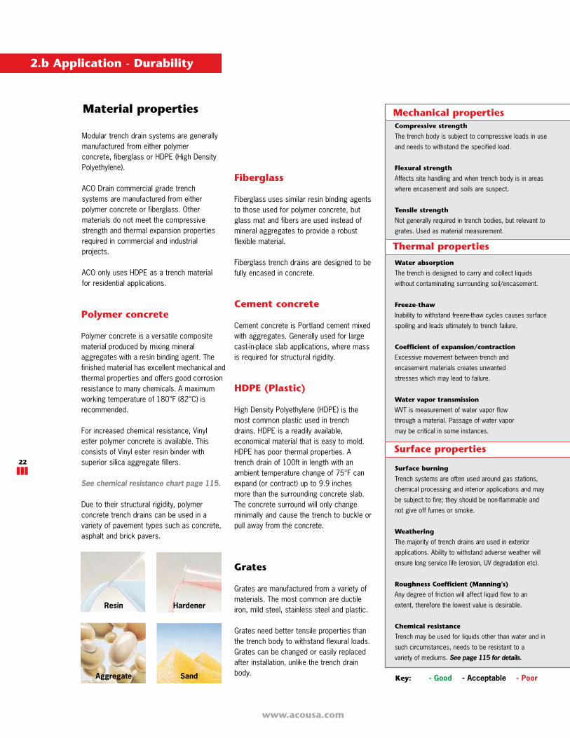
Polymer concrete
Polymer concrete is a versatile compositematerial produced by mixing mineralaggregates with a resin binding agent. Thefinished material has excellent mechanical andthermal properties and offers good corrosionresistance to many chemicals. A maximumworking temperature of 180°F (82°C) isrecommended.
For increased chemical resistance, Vinylester polymer concrete is available. Thisconsists of Vinyl ester resin binder withsuperior silica aggregate fillers.
See chemical resistance chart page 115.
Due to their structural rigidity, polymerconcrete trench drains can be used in avariety of pavement types such as concrete,asphalt and brick pavers.
Material properties
HardenerResin
Aggregate Sand
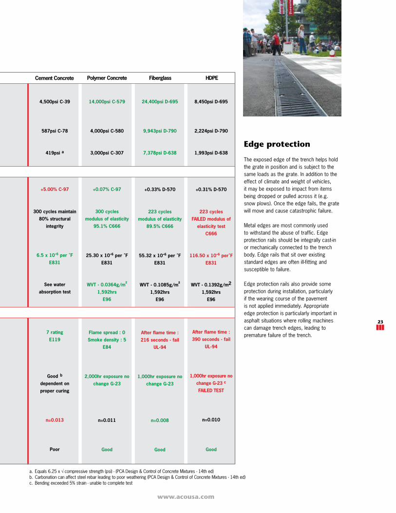
Mechanical properties
Thermal properties
Key: - Good - Acceptable - Poor
Compressive strength
The trench body is subject to compressive loads in use
and needs to withstand the specified load.
Flexural strength
Affects site handling and when trench body is in areas
where encasement and soils are suspect.
Tensile strength
Not generally required in trench bodies, but relevant to
grates. Used as material measurement.
Water absorption
The trench is designed to carry and collect liquids
without contaminating surrounding soil/encasement.
Freeze-thaw
Inability to withstand freeze-thaw cycles causes surface
spoiling and leads ultimately to trench failure.
Coefficient of expansion/contraction
Excessive movement between trench and
encasement materials creates unwanted
stresses which may lead to failure.
Water vapor transmission
WVT is measurement of water vapor flow
through a material. Passage of water vapor
may be critical in some instances.
Surface burning
Trench systems are often used around gas stations,
chemical processing and interior applications and may
be subject to fire; they should be non-flammable and
not give off fumes or smoke.
Weathering
The majority of trench drains are used in exterior
applications. Ability to withstand adverse weather will
ensure long service life (erosion, UV degradation etc).
Roughness Coefficient (Manning’s)
Any degree of friction will affect liquid flow to an
extent, therefore the lowest value is desirable.
Chemical resistance
Trench may be used for liquids other than water and in
such circumstances, needs to be resistant to a
variety of mediums. See page 115 for details.
Surface properties
2.b Application - Durability
ACO DRAIN
www.acousa.com
23
Edge protection
The exposed edge of the trench helps holdthe grate in position and is subject to thesame loads as the grate. In addition to theeffect of climate and weight of vehicles,it may be exposed to impact from itemsbeing dropped or pulled across it (e.g.snow plows). Once the edge fails, the gratewill move and cause catastrophic failure.
Metal edges are most commonly usedto withstand the abuse of traffic. Edgeprotection rails should be integrally cast-inor mechanically connected to the trenchbody. Edge rails that sit over existingstandard edges are often ill-fitting andsusceptible to failure.
Edge protection rails also provide someprotection during installation, particularlyif the wearing course of the pavementis not applied immediately. Appropriateedge protection is particularly important inasphalt situations where rolling machinescan damage trench edges, leading topremature failure of the trench.
a. Equals 6.25 x compressive strength (psi) - (PCA Design & Control of Concrete Mixtures - 14th ed)b. Carbonation can affect steel rebar leading to poor weathering (PCA Design & Control of Concrete Mixtures - 14th ed)c. Bending exceeded 5% strain - unable to complete test
8,450psi D-695
2,224psi D-790
1,993psi D-638
+0.31% D-570
223 cycles
FAILED modulus of
elasticity test
C666
116.50 x 10⁻⁶ per˚F
E831
WVT - 0.1392g/m2
1,592hrs
E96
After flame time :
390 seconds - fail
UL-94
1,000hr exposure no
change G-23 c
FAILED TEST
n=0.010
Good
4,500psi C-39
587psi C-78
419psi a
+5.00% C-97
300 cycles maintain
80% structural
integrity
6.5 x 10⁻⁶ per ˚F
E831
See water
absorption test
7 rating
E119
Good b
dependent on
proper curing
n=0.013
Poor
14,000psi C-579
4,000psi C-580
3,000psi C-307
+0.07% C-97
300 cycles
modulus of elasticity
95.1% C666
25.30 x 10⁻⁶ per ˚F
E831
WVT - 0.0364g/m²
1,592hrs
E96
Flame spread : 0
Smoke density : 5
E84
2,000hr exposure no
change G-23
n=0.011
Good
24,400psi D-695
9,943psi D-790
7,378psi D-638
+0.33% D-570
223 cycles
modulus of elasticity
89.5% C666
55.32 x 10⁻⁶ per ˚F
E831
WVT - 0.1085g/m²
1,592hrs
E96
After flame time :
216 seconds - fail
UL-94
1,000hr exposure no
change G-23
n=0.008
Good
Cement Concrete Polymer Concrete Fiberglass HDPE
www.acousa.com
24
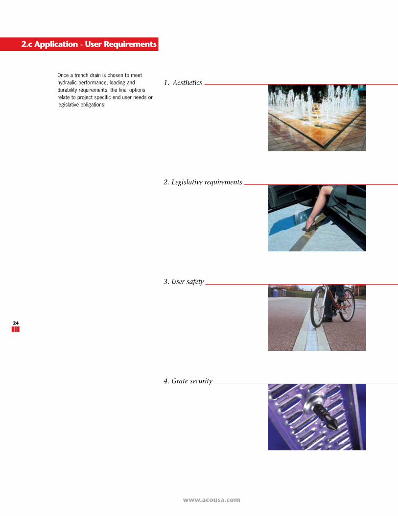
1. Aesthetics
2. Legislative requirements
3. User safety
4. Grate security
Once a trench drain is chosen to meethydraulic performance, loading anddurability requirements, the final optionsrelate to project specific end user needs orlegislative obligations:
2.c Application - User Requirements
ACO DRAIN
www.acousa.com
25
No US Standard exists detailingslot sizes to avoid bicycle tiresbecoming trapped.
Australian Standard AS 3996 - 2006Clause 3.3.6 specifies maximum slot lengthdependent on slot width for grates that aredeemed ‘Bicycle Tire Penetration Resistant.’
ACO offers bicycle safe grates determinednot to have slots large enough to trapmodern bicycle wheels based on thisAustralian Standard.
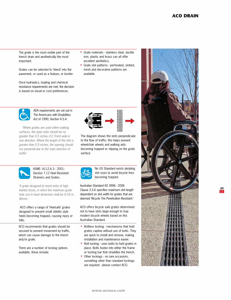
ADA requirements are set out inThe Americans with DisabilitiesAct of 1990; Section 4.5.4.
‘Where grates are used within walking surfaces, the open slots should be no greater than 0.5 inches (12.7mm) wide in one direction. Where the length of the slot is greater than 0.5 inches, the opening should run perpendicular to the main direction of traffic’
The grate is the most visible part of thetrench drain and aesthetically the mostimportant.
Grates can be selected to ‘blend’ into thepavement, or used as a feature, or border.
Once hydraulics, loading and chemicalresistance requirements are met, the decisionis based on visual or cost preferences.
• Grate materials - stainless steel, ductileiron, plastic and brass can all offerexcellent aesthetics.
• Grate slot patterns - perforated, slotted,mesh and decorative patterns areavailable.
ACO recommends that grates should besecured to prevent movement by traffic,which can cause damage to the trenchand/or grate.
There are a number of locking optionsavailable, these include:
ASME: A112.6.3 - 2001:Section 7.12 Heel ResistantStrainers and Grates.
‘A grate designed to resist entry of high-heeled shoes, in which the maximum grate hole size in least dimension shall be 5/16 in. (8mm).'
ACO offers a range of ‘Heelsafe’ gratesdesigned to prevent small stiletto styleheels becoming trapped, causing injury orfalls.
• Boltless locking - mechanisms that holdgrates captive without use of bolts. Theyare quick to install and remove, makinginstallation and maintenance easier.
• Bolt locking - uses bolts to hold grates inplace. Bolts fasten into either the frameor locking bar that straddles the trench.
• Other lockings - on rare occasions,something other than standard lockingsare required - please contact ACO.
The diagram shows the slots perpendicularto the flow of traffic; this helps preventwheelchair wheels and walking aidsbecoming trapped or slipping on the gratesurface.