acknowledgment of sponsorshippart 3- design analysis, chapter 5 identification of feasible...
TRANSCRIPT


ACKNOWLEDGMENT OF SPONSORSHIP
This work was sponsored by the American Association of State Highway and Transportation Officials, in cooperation with the Federal Highway Administration, and was conducted in the National Cooperative Highway Research Program, which is administered by the Transportation Research Board of the National Research Council.
DISCLAIMER
This is the final draft as submitted by the research agency. The opinions and conclusions expressed or implied in the report are those of the research agency. They are not necessarily those of the Transportation Research Board, the National Research Council, the Federal Highway Administration, the American Association of State Highway and Transportation Officials, or the individual states participating in the National Cooperative Highway Research Program.

PART 3—DESIGN ANALYSIS
CHAPTER 7 PCC REHABILITATION DESIGN OF EXISTING PAVEMENTS
3.7.1 INTRODUCTION This chapter describes the mechanistic-empirical design procedures for rehabilitation of existing flexible, rigid, and composite pavements with portland cement concrete (PCC). Lane additions and widening of narrow lanes are also considered. Note that many aspects of rehabilitation design are similar to new design, and this chapter often references PART 3, Chapter 4 to avoid duplication. For this reason, the designer should become familiar with PART 3, Chapter 4 prior to using this chapter for design of rehabilitation of existing pavements with PCC. 3.7.1.1 Background PCC can be used to remedy functional or structural deficiencies of all types of existing pavements. It is important for the designer to consider several aspects, including the type of deterioration present, before determining the appropriate rehabilitation strategy to adopt. Several different rehabilitation strategies using PCC can be applied to existing pavements to extend their useful service life. These range from the combination of repair and preventive treatments such as full-depth repair and diamond grinding of existing jointed plain concrete pavement (JPCP) to the placement of unbonded JPCP or continuously reinforced concrete pavement (CRCP) overlays over existing flexible, composite, or rigid pavements, to the placement of bonded PCC overlays over existing JPCP or CRCP, to the reconstruction (including adding additional lanes) of existing pavements with JPCP or CRCP as described in PART 3, Chapter 5 of this Guide. These strategies are commonly used to remedy functional, structural, or other inadequacies. 3.7.1.2 Scope This chapter presents detailed design procedures for the following PCC rehabilitation strategies:
• Design of concrete pavement restoration (CPR) for JPCP. • Design of unbonded JPCP or CRCP overlays over existing rigid and composite
pavements. • Design of bonded PCC overlays over existing JPCP or CRCP. • Design of conventional JPCP or CRCP overlays over existing flexible pavements.
In addition, general guidelines are provided for design of additional traffic lanes. However, the detailed design is provided in PART 3, Chapter 4. The design of ultra-thin concrete overlays of existing asphalt pavements is not covered in this Guide. The American Concrete Pavement Association (ACPA) Technical Bulletin TB009P, Guidelines for Concrete Overlays over Existing Asphalt Pavements, provides guidance for this design (1). Throughout this chapter, bonded PCC over existing JPCP or CRCP overlays are generally described as bonded JPCP and CRCP overlays. Also, conventional JPCP or CRCP overlays over existing flexible pavements are described as JPCP or CRCP overlays over existing flexible pavements.
3.7.1

3.7.2
3.7.1.3 Organization The mechanistic-empirical design of rehabilitated pavements requires an iterative, hands-on approach by the designer. The designer must select a proposed trial rehabilitation design and then analyze the design in detail to determine whether it meets the applicable performance criteria (i.e., joint faulting and slab cracking for JPCP, punchouts for CRCP, and smoothness for both JPCP and CRCP) established by the designer. If a particular trial rehabilitation design does not meet the performance criteria, the design is modified and reanalyzed until it meets the criteria. The designs that meet the applicable performance criteria are then considered feasible from a structural and functional viewpoint and can be further considered for other evaluations, such as life cycle cost analysis (LCCA). This chapter first provides an overview of the rehabilitation with PCC design process. It then describes in detail the design procedure for rehabilitation with JPCP, followed by the design procedure for rehabilitation with CRCP. Note that rehabilitation with JPCP or CRCP describes the topmost layer of the rehabilitated pavement and not necessarily the type of existing pavement to be rehabilitated. Also included in this chapter are sensitivity analyses for factors that affect JPCP and CRCP overlay design and recommendations for modifications of design if a particular trial design does not meet the agency performance criteria. Following this introduction are the following sections:
• Section 3.7.2—Overview of rehabilitation with PCC design process. • Section 3.7.3—Rehabilitation design requirements. • Section 3.7.4—Rehabilitation design of JPCP, including sensitivity analysis and
recommendations for design modifications to meet agency performance criteria. • Section 3.7.5—Rehabilitation design of CRCP, including sensitivity analysis and
recommendations for design modifications to meet agency performance criteria. • Section 3.7.6—Additional considerations for rehabilitation design with PCC.
The design procedures described in this chapter can utilize recycled materials. The use of recycled materials in rehabilitation is acceptable so far as the material properties can be characterized by the parameters used in design and the recycled material meets durability requirements. 3.7.2 OVERVIEW OF REHABILITATION DESIGN PROCESS Figure 3.7.1 shows the flow of the PCC rehabilitation design process presented in this Guide. Actual structural design of feasible rehabilitation strategies is step 6 of the following pavement rehabilitation procedure:
• Steps 1-4: Evaluation of the existing pavement (PART 2, Chapter 5). o Step 1: Determine existing pavement condition. o Step 2: Determine causes and mechanism of distress. o Step 3: Define problems and inadequacies of existing pavement. o Step 4: Identify possible constraints.

Step 1Determine Existing Pavement Condition
Step 2Determine Causes and Mechanism of Distress
Step 3Define Problems and Inadequacies of Existing Pavement
Step 4Identify Possible Constraints
Step 5Select Feasible Rehabilitation Strategies
Step 6Develop Preliminary Design of Each Feasible Strategy
Step 7Perform Life Cycle Cost Analysis
Step 8Determine Non-Monetary Factors that Influence Rehabilitation
Step 9Determine Preferred Rehabilitation Strategy
Part 2- DESIGN INPUTS, Chapter 5Evaluation of Existing Pavements for Rehabilitation
Concrete Pavement Restoration
Unbonded PCC Overlaysover Existing Rigid Pavements
Bonded PCC Overlaysover Existing JPCP or CRCP
PCC Overlays over Existing Flexible Pavements
Reconstruction with PCC
Part 3—DESIGN ANALYSIS, Chapter 7PCC Rehabilitation Design of Existing Paveme
Appendix C—Economic and Life Cycle Cost Analysis
Part 3- DESIGN ANALYSIS, Chapter 5Identification of Feasible Rehabilitation Alternatives
Part 3- DESIGN ANALYSIS, Chapter 5Identification of Feasible Rehabilitation Alternatives
Figure 3.7.1. Overall PCC rehabilitation design process.
3.7.3
• Step 5: Rehabilitation strategy selection (PART 3, Chapter 5). • Step 6: Rehabilitation design (PART 3, Chapter 7). • Step 7: Perform life cycle cost analysis (as desired). • Step 8: Determine non-monetary factors that influence rehabilitation (as desired). • Step 9: Determine preferred rehabilitation strategy (as desired).
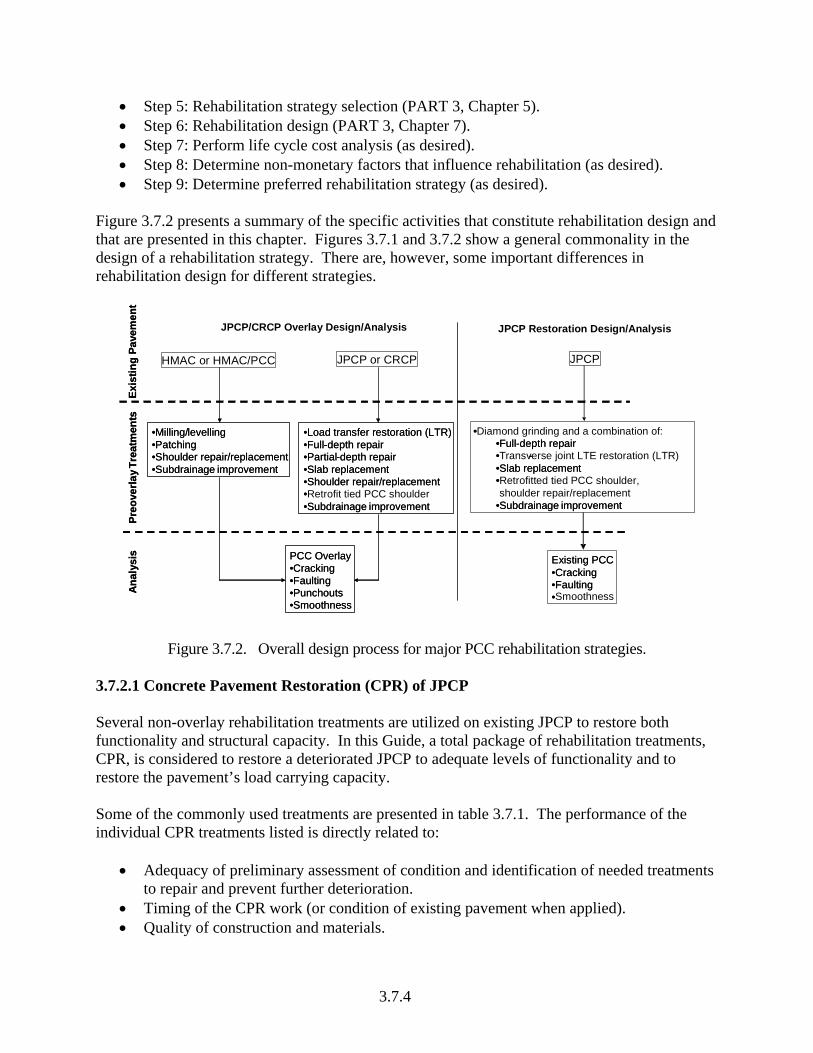
Figure 3.7.2 presents a summary of the specific activities that constitute rehabilitation design and that are presented in this chapter. Figures 3.7.1 and 3.7.2 show a general commonality in the design of a rehabilitation strategy. There are, however, some important differences in rehabilitation design for different strategies.
Exis
ting
Pave
men
t
JPCP or CRCP
Preo
verla
yTre
atm
ents
•Milling/levelling•Patching•Shoulder repair/replacement•Subdrainage improvement
•Load transfer restoration (LTR)•Full-depth repair•Partial-depth repair•Slab replacement•Shoulder repair/replacement •Retrofit tied PCC shoulder•Subdrainage improvement
•Diamond grinding and a combination of:•Full-depth repair•Transverse joint LTE restoration (LTR)-•Slab replacement•Retrofitted tied PCC shoulder, shoulder repair/replacement
•Subdrainage improvement
Ana
lysi
s PCC Overlay•Cracking•Faulting•Punchouts•Smoothness
Existing PCC•Cracking•Faulting•
Exis
ting
Pave
men
t
HMAC or HMAC/PCC
JPCP/CRCP Overlay Design/Analysis JPCP Restoration Design/Analysis
Preo
verla
yTre
atm
ents
•Milling/levelling•Patching•Shoulder repair/replacement•Subdrainage improvement
•Load transfer restoration (LTR)•Full-depth repair•Partial-depth repair•Slab replacement•Shoulder repair/replacement ••Subdrainage improvement
••Full-depth repair• -•Slab replacement•
•Subdrainage improvement
Ana
lysi
s PCC Overlay•Cracking•Faulting•Punchouts•Smoothness
Existing PCC•Cracking•Faulting•Smoothness
JPCP
Figure 3.7.2. Overall design process for major PCC rehabilitation strategies.
3.7.2.1 Concrete Pavement Restoration (CPR) of JPCP Several non-overlay rehabilitation treatments are utilized on existing JPCP to restore both functionality and structural capacity. In this Guide, a total package of rehabilitation treatments, CPR, is considered to restore a deteriorated JPCP to adequate levels of functionality and to restore the pavement’s load carrying capacity. Some of the commonly used treatments are presented in table 3.7.1. The performance of the individual CPR treatments listed is directly related to:
• Adequacy of preliminary assessment of condition and identification of needed treatments to repair and prevent further deterioration.
• Timing of the CPR work (or condition of existing pavement when applied). • Quality of construction and materials.
3.7.4

Table 3.7.1. Candidate repair and preventive treatments for existing JPCP (2–11).
Distress Repair Treatments Preventive Treatments
Jointed concrete pavement pumping (and low joint load transfer efficiency)
—
• Reseal joints • Restore joint load transfer • Subdrainage • Edge support (tied PCC shoulder)
Jointed concrete pavement joint faulting
Diamond grinding Structural overlay
• Reseal joints • Restore load transfer • Subdrainage
Jointed concrete pavement slab cracking
Full-depth PCC repair Slab replacement Replace/recycle lane
• Retrofit tied PCC shoulder • Restore load transfer • Bonded and unbonded PCC overlays • Thick HMA overlays
Jointed concrete pavement joint or crack spalling
Full-depth PCC repair Partial-depth repair • Clean and reseal joints
PCC disintegration (e.g., D-cracking and alkali-silica reaction [ASR])
Full-depth repair • Thick hot mix AC overlay • Unbonded PCC overlay
Properly designed and constructed CPR should reduce pavement deterioration and prolong pavement life. One study of projects across the U.S. built in the 1980’s showed that CPR projects (with diamond grinding for JPCP) resulted in an average life extension of 13 years if adequate maintenance is applied (2, 3). The data showed that over 90 percent of the CPR projects lasted 10 years or more. Performance also depends on the types of treatments applied. If only repair treatments are applied to existing distress, the mechanism causing the distress will continue its destructive work immediately when the pavement is opened to traffic, resulting in premature rehabilitation failures. Therefore, after each distress type has been repaired with an appropriate CPR treatment, one or more preventive treatments must be applied to provide a cost-effective rehabilitation strategy and ensure adequate performance. For pavements with multiple distresses, the most suitable combination of repair and preventive treatments must be applied, as shown in table 3.7.1. The design and construction procedures of individual CPR treatments are described in detail in several publications, including references 4–10:
• TB002P—Guidelines for full-depth repair. • TB003P—Guidelines for partial-depth repair. • TB008P—Diamond grinding and CPR 2000. • TB012P—Joint and crack sealing repair for concrete pavements (including cross-
stitching). • TB018P—Slab stabilization for concrete pavements. • TB020P—Concrete pavement restoration guide. • Concrete Pavement Rehabilitation—Guide for Diamond Grinding.
3.7.5

Guidelines are presented in this Guide for the performance evaluation of selected CPR treatment designs to determine their effectiveness as a pavement rehabilitation strategy. CPR is not applicable to rigid pavements that have significant material durability problems, structural deficiency, or other severe deterioration. Note that the design of existing rigid pavements subjected to CPR is limited to JPCP. Also, CPR in this context is defined as diamond grinding and any combination of repair treatments such as full-depth repair and load transfer restoration. 3.7.2.2 Overlay Rehabilitation Options Bonded PCC Overlay of Existing JPCP or CRCP Bonded PCC overlays over existing JPCP or CRCP involve the placement of a thin concrete layer atop the prepared existing JPCP or CRCP surface to form a permanent monolithic PCC section. Achieving a long-term bond is essential for good performance. Thus, the existing PCC slab must be in sound condition to help ensure good bonding and little reflection cracking. A detailed discussion on how to achieve good bonding between the overlay and existing PCC is presented in section 3.7.6. The monolithic section improves load carrying capacity by reducing the critical structural responses—top and bottom tensile stress in the longitudinal direction for JPCP cracking and slab edge corner deflections at the joint for JPCP faulting. For CRCP, the critical structural response—tensile bending stress in the transverse direction between two closely spaced transverse cracks—is also reduced. The critical longitudinal and transverse tensile stresses and slab edge corner deflections are reduced when a monolithic slab is formed by the overlay and existing pavement PCC, resulting in less damage per load application and, consequently, a substantial increase in load capacity. It also provides a new surface for improved rideability and friction resistance (12, 13). Unbonded JPCP/CRCP Overlay of Existing Rigid Pavement Unbonded concrete overlays range from thin (6 to 8 in) to thick (9 to 12 in) concrete layers placed on top of any of the following (with an appropriate separation layer):
• Existing intact concrete pavement (JPCP, JRCP, or CRCP). • Existing composite (AC/PCC) pavement. • Fractured PCC pavement (crack and seat, break and seat, or rubblized PCC).
Unbonded JPCP or CRCP overlays can be a cost-effective rehabilitation alternative for badly deteriorated rigid or composite pavements. Unbonded overlays with an adequate AC separator layer behave structurally as if built on a strong non-erodible base course (14, 15). Unbonded overlays (over intact PCC slab) do not require much pre-overlay repair because of a separator layer placed between the overlay and existing pavement. The separator layer (sometimes called a debonding layer or stress relief layer) is usually a thin hot mix asphalt concrete layer 1 to 2 in thick. The purpose of the separator layer is to separate the existing and overlay concrete layers so that they may respond independently of each other when subjected to axle loads and temperature cycles. The separator layer also prevents distresses in the existing pavement from
3.7.6

reflecting through the overlay. Guidance is provided in this chapter for the design of unbonded concrete overlays over existing rigid pavements (14, 15). Concrete Overlay of Existing Flexible Pavement Conventional concrete overlays (CCOL) and ultra-thin concrete overlays (UTCOL) can be applied to existing flexible pavements. Conventional PCC overlays consist of a thin to thick concrete layer (typically 5 in or more) placed over an existing flexible pavement. When subjected to axle loads, the overlaid pavement behaves just like a new concrete pavement (with a hot mix asphalt concrete [AC]) base course with varying levels of deterioration). Conventional concrete overlays are generally effective when applied to existing flexible pavements, and they have been used successfully on Interstate highways, State primary and secondary roads, and intersections (16, 17). It is strongly desirable to have bond between the PCC and the AC layer to reduce erosion, maximize structural benefits, and properly form the longitudinal and transverse joints. A conventional concrete overlay over an existing flexible pavement offers several advantages. First, it requires minimal pre-overlay repair because of slabs ability to bridge deterioration. Second, the existing asphalt makes a good base course with the same advantages of other stabilized base materials—reduced potential for pumping, faulting, loss of support, adequate friction with slab, and punchouts. Ultra-thin concrete overlays over existing flexible pavements refer to a thin PCC overlay (2 to 4 in thick) placed over an existing flexible pavement. In addition to being thinner, two other factors differentiate UTCOL from CCOL (1, 16, 17, 18):
• There must be a full bond between the ultra-thin concrete overlay layer and the top of the existing asphalt bound layer.
• They have very short joint spacing—2 to 6 ft compared to a typical joint spacing of 12 to 18 ft for conventional concrete overlays.
Bonding of the concrete overlay to the asphalt pavement creates a composite section in which the load is shared between the concrete and existing asphalt. The shorter joint spacing allows the slabs to deflect more and bend less, reducing bending stresses in the overlay slabs. UTCOL is applied only where a substantial thickness of AC exists in good condition. UTCOL is a potential application for normal traffic loads on residential streets and low-volume roads. Other applications include lower truck volume AC-surfaced intersections where rutting and washboarding is a problem and AC-surfaced parking areas. Procedures are provided in this chapter for the design of conventional concrete overlays over existing flexible pavements. Procedures for the mechanistic design of ultra-thin concrete overlays over existing flexible pavements are included in the APCA Bulletins RP-273P and EB-210P (16, 17).
3.7.7
3.7.8
Reconstruction When pavement deteriorates to the point where the typical rehabilitation strategies are no longer cost-effective, or when the geometrics must be changed, the most feasible rehabilitation strategy may be reconstruction with hot mix AC or PCC. Reconstruction involves removing some or all of the pavement structure and replacing it. The design of reconstructed pavements is similar to that for new pavements; therefore, the design guidelines presented in PART 3, Chapter 4 should be applied. The addition of a traffic lane or the widening of narrow PCC slabs is presented in section 3.7.6 of this chapter. 3.7.3 DESIGN INPUTS FOR PCC REHABILITATION DESIGN Input data used for the design of rehabilitation with PCC presented in this chapter are summarized in table 3.7.2 and categorized as follows:
• General information. • Site/project identification. • Analysis parameters. • Traffic. • Climate. • Pavement structure. • Pavement design features.
o Drainage and surface properties. o Layer definition and material properties.
• Rehabilitation. Several of these inputs are identical to those used for new pavement design, presented in PART 3, Chapter 4, and are not repeated here. However, there are variations in how some these inputs are selected for use in rehabilitation design. The focus of this section is to summarize all the inputs required for the design of rehabilitation with PCC using the Design Guide approach with appropriate commentary on how they relate to the design process. For many design features, materials, and climatic inputs, the designer can choose any of three methods or levels of inputs that range from actual testing and measurements (e.g., laboratory testing of concrete strength, on site traffic measurements, and pavement coring) to regional or statewide default values (typical values based on historical testing results in a region). A detailed description of the three input levels is described in PART 1, Chapter 1 and PART 2, Chapters 1 through 5. Detailed descriptions for several of these inputs were presented in previous chapters of the Guide as indicated below: • Part 2, Chapter 1: Subgrade/Foundation Inputs. • Part 2, Chapter 2: Material Characterization. • Part 2, Chapter 3: Environmental Effects. • Part 2, Chapter 4: Traffic Loadings. • Part 2, Chapter 5: Evaluation of Existing Pavements for Rehabilitation. • Part 3, Chapter 1: Subdrainage.

3.7.9
Table 3.7.2. Design inputs and requirements for rehabilitation design with PCC.
Rehabilitation Type General Description Variable Existing JPCP
subjected to CPR JPCP
Overlays1CRCP
Overlays2
Project name and description Design life, years Existing pavement construction date Pavement overlay construction date Pavement restoration construction date Traffic opening date
General information
Type of rehabilitation strategy Location of the project Project identification Site/project
identification Functional class Analysis type (deterministic or probabilistic) Initial smoothness (after rehabilitation) Analysis parameters
Performance criteria Hourly profiles of temperature distribution through PCC slab Hourly temperature and moisture profiles (including frost depth calculations) through the other pavement layers
Zero stress temperature for JPCP and CRCP overlay design Monthly or semi-monthly (during frozen or recently frozen periods) predictions of layer moduli for asphalt, unbound base/subbase, and subgrade layers
Mean annual freezing index, number of wet days, number of air freeze-thaw cycles
Climate
Mean monthly relative humidity. AADTT, percent trucks, vehicle speed, and others Traffic volume adjustment factors Axle load adjustment factors Traffic
Wheel location, traffic wander, and others 1. PCC bonded overlays of existing JPCP and JPCP overlays of existing flexible pavements. 2. PCC bonded overlays of existing CRCP and CRCP overlays of existing flexible pavements.

3.7.10
Table 3.7.2. Design requirements for rehabilitation design with PCC, continued.
Rehabilitation Type General Description Variable Existing JPCP
subjected to CPR JPCP
Overlays1CRCP
Overlays2
Pavement surface layer (PCC) shortwave absorptivity Potential for infiltration Pavement cross slope
Drainage and surface properties
Length of drainage path Layer number, description, and material type Layer thickness Elastic modulus Flexural, compressive, and tensile strength Ultimate shrinkage Unit weight, Poisson’s ratio Coefficient of thermal expansion
Layer definition and material properties
Thermal conductivity, heat capacity, etc. Permanent curl/warp (effective temperature difference) in PCC slab due to construction curling and moisture warping
Transverse joint spacing (average or random) Transverse joint sealant type Dowel diameter and spacing Edge support (tied PCC, widened lane, slab width, etc.) Lane-shoulder joint load transfer efficiency (LTE) (for tied PCC shoulders) Slab width (for widened slabs) Number of years after which PCC/base interface is unbonded Nbond (for JPCP with a stabilized base) Base erodibility index Total longitudinal steel cross-sectional area as percent of PCC slab cross-sectional area Diameter of longitudinal reinforcing steel Depth of steel placement from pavement surface PCC slab/base friction coefficient1
Design features
Crack spacing (mean and standard deviation)

Table 3.7.2. Design requirements for rehabilitation design with PCC, continued.
Rehabilitation Type General Description Variable Existing JPCP
subjected to CPR JPCP
Overlays1CRCP
Overlays2
Existing distress—percent slabs with transverse cracks plus previously replaced slabs
Percent of slabs with repairs after restoration Foundation support—modulus of subgrade reaction
Rehabilitation
Month modulus of subgrade reaction was measured
3.7.11

• Part 3, Chapter 2: Shoulders. • Part 3, Chapter 4: Design of New and Reconstructed Rigid Pavements. This chapter does not repeat the detailed descriptions of the required inputs. It is recommended that the chapters listed above be referenced for a more comprehensive description of the inputs required. 3.7.3.1 General Information General information is described in table 3.7.3. The data range in simplicity from project name to rehabilitation strategy type—a key input parameter since most of the subsequent input data depends on it. For JPCP rehabilitation without overlays and rehabilitation with JPCP or CRCP overlays, the Guide presents PCC rehabilitation strategies for consideration.
Table 3.7.3. General information required for PCC rehabilitation strategy design.
Input Variable Description/Source of Information
Project name and description • User input Design life • Expected rehabilitation design life Existing pavement construction date
• Month in which existing pavement was constructed • Year in which existing pavement was constructed
Pavement overlay construction date1
• Month in which PCC overlay construction is expected • Year in which PCC overlay construction is expected
Pavement restoration date2 • Month in which existing PCC restoration is expected • Year in which existing PCC is restoration is expected
Traffic opening date
• Expected month in which rehabilitated pavement will be opened to traffic
• Expected year in which rehabilitated pavement will be opened to traffic
Type of rehabilitation strategy
• JPCP rehabilitation without overlays 1. Existing JPCP subjected to CPR3
• Rehabilitation with JPCP or CRCP overlays 1. Existing JPCP, JRCP, CRCP, or composite overlaid with
unbonded JPCP overlay 2. Existing JPCP, JRCP, CRCP, or composite overlaid with
unbonded CRCP overlay 3. Existing JPCP and CRCP overlaid with bonded PCC overlay 4. Existing flexible pavement overlaid with JPCP overlay 5. Existing flexible pavement overlaid with CRCP overlay
1. Applicable to PCC overlays only. 2. Applicable to existing JPCP subjected to CPR only. 3. CPR is defined as diamond grinding with a combination of CPR treatments such as full-depth patching, load transfer restoration, shoulder replacement, and lane widening.
3.7.12
3.7.3.2 Site/Project Identification These set of inputs identify the following features with regard to the project being designed:
• Location of the project. • Project identification – Project ID, Section ID, begin and end mile posts, and traffic
direction. 3.7.3.3 Analysis Parameters Initial Smoothness Recommendations for initial smoothness (measured as International Roughness Index, IRI) are similar to new construction for JPCP and CRCP overlays. They depend greatly on the project smoothness specifications. The estimate of initial smoothness for restored JPCP (for this design procedure restoration must always include diamond grinding) depends on the diamond grinding specifications. It may, however, need to be adjusted upward if a significant amount of settlements or heaves exist, as this cannot be easily rectified through diamond grinding alone. Local leveling such as slab jacking or thin localized overlays may be needed. Performance Criteria
Performance criteria are definitions of the maximum amounts of individual distress or smoothness acceptable to the highway agency at a given reliability level. Performance indicators used for rehabilitation design are as follows:
• Transverse joint faulting, transverse cracking and smoothness (IRI) for existing JPCP subjected to CPR or JPCP overlays.
• Crack width, crack LTE, punchouts and smoothness for CRCP overlays. Performance criteria are a user input and depend on local design and rehabilitation policies. The designer can select one, two, or all three of these performance criteria available to evaluate a design and make modifications if necessary. See PART 3, Chapter 4 for detailed recommendations. 3.7.3.4 Traffic Traffic data is one of the key data elements required for the analysis and design of rehabilitated pavement structures. The design procedures for all the different types of rehabilitation with PCC are based on future traffic estimates. Estimates of load spectra for single, tandem, tridem, and quad axles are used to characterize traffic for rehabilitation with PCC design. This load spectra includes the counts of number of axles within a series of load groups in a given time interval. Each load group covers a specified load interval for a specific axle. Detailed guidance on traffic inputs required for rehabilitation design is presented in PART 2, Chapter 4. Further information on traffic inputs is provided in PART 3, Chapter 4 relative to PCC pavements. Traffic inputs for rehabilitation design are identical to those for new design.
3.7.13

3.7.3.5 Climate Environmental conditions have a significant effect on the performance of PCC rehabilitated pavements. The interaction of the climatic factors with pavement materials and loading is fairly complex. Factors such as precipitation, temperature, freeze-thaw cycles, and depth to water table affect pavement and subgrade temperature and moisture content, which, in turn, directly affect the load-carrying capacity of the pavement layers and ultimately pavement performance. In the Design Guide approach, the temperature and moisture profiles in the pavement structure and subgrade are determined using the Enhanced Integrated Climatic Model (EICM). The EICM software is linked to the Design Guide software as an independent module through interfaces and design inputs. Detailed guidance on environmental inputs required for pavement design is presented in PART 2, Chapter 3. Further information specifically for rigid pavements is given in PART 3, Chapter 4. 3.7.3.6 Pavement Structure The rehabilitated pavement structure can be characterized into three categories namely; pavement design features, drainage and surface properties, and layer definition and material properties. These are all key input requirements. The information used to characterize the pavement structure is categorized as follows:
• Pavement design features. o Permanent curling/warping. o Joint spacing, etc. o Presence of dowels, dowel diameter, and dowel spacing.
• Drainage and surface properties. o Pavement surface layer (PCC) shortwave absorptivity. o Potential for infiltration. o Pavement cross slope. o Length of drainage path.
• Layer definition and material properties. o Layer number, description, and material type. o Layer thickness. o Elastic modulus. o Flexural, compressive, and tensile strength. o Ultimate shrinkage. o Unit weight. o Poisson’s ratio. o Coefficient of thermal expansion of PCC. o Thermal conductivity. o Heat capacity, etc. o PCC zero stress temperature.
Detailed descriptions of the data required are presented in the following sections.
3.7.14
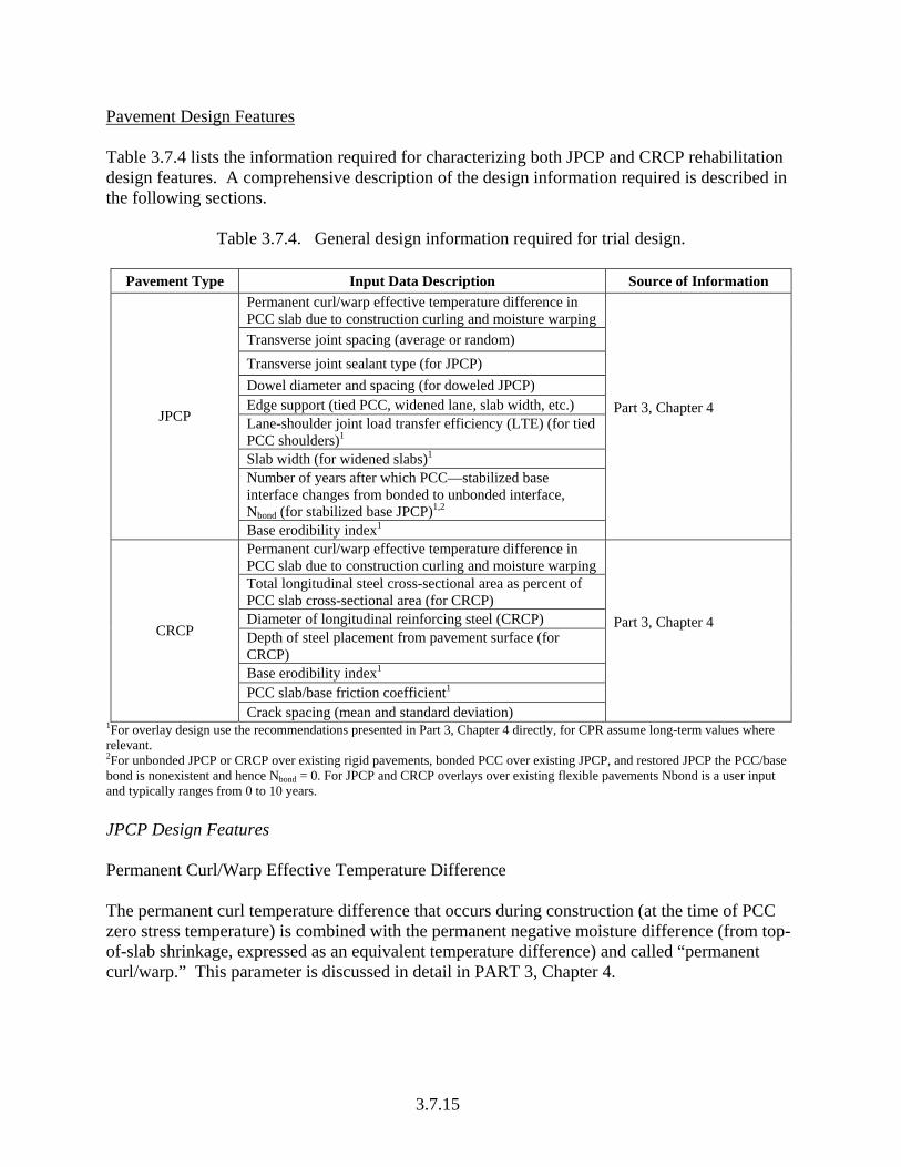
Pavement Design Features Table 3.7.4 lists the information required for characterizing both JPCP and CRCP rehabilitation design features. A comprehensive description of the design information required is described in the following sections.
Table 3.7.4. General design information required for trial design.
Pavement Type Input Data Description Source of Information
Permanent curl/warp effective temperature difference in PCC slab due to construction curling and moisture warping Transverse joint spacing (average or random) Transverse joint sealant type (for JPCP) Dowel diameter and spacing (for doweled JPCP) Edge support (tied PCC, widened lane, slab width, etc.) Lane-shoulder joint load transfer efficiency (LTE) (for tied PCC shoulders)1
Slab width (for widened slabs)1
Number of years after which PCC—stabilized base interface changes from bonded to unbonded interface, Nbond (for stabilized base JPCP)1,2
JPCP
Base erodibility index1
Part 3, Chapter 4
Permanent curl/warp effective temperature difference in PCC slab due to construction curling and moisture warping Total longitudinal steel cross-sectional area as percent of PCC slab cross-sectional area (for CRCP) Diameter of longitudinal reinforcing steel (CRCP) Depth of steel placement from pavement surface (for CRCP) Base erodibility index1
PCC slab/base friction coefficient1
CRCP
Crack spacing (mean and standard deviation)
Part 3, Chapter 4
1For overlay design use the recommendations presented in Part 3, Chapter 4 directly, for CPR assume long-term values where relevant. 2For unbonded JPCP or CRCP over existing rigid pavements, bonded PCC over existing JPCP, and restored JPCP the PCC/base bond is nonexistent and hence Nbond = 0. For JPCP and CRCP overlays over existing flexible pavements Nbond is a user input and typically ranges from 0 to 10 years. JPCP Design Features Permanent Curl/Warp Effective Temperature Difference The permanent curl temperature difference that occurs during construction (at the time of PCC zero stress temperature) is combined with the permanent negative moisture difference (from top-of-slab shrinkage, expressed as an equivalent temperature difference) and called “permanent curl/warp.” This parameter is discussed in detail in PART 3, Chapter 4.
3.7.15

3.7.16
Joint Design Joint Spacing. The joint spacing significantly affects transverse cracking and, to a lesser degree, joint faulting. Field studies have shown that the longer the joint spacing, the greater the potential for the JPCP to experience transverse cracking and joint faulting. For restored JPCP and bonded PCC over JPCP overlays the joint spacing of the existing pavement is assumed using information obtained during pavement evaluation as outlined in PART 2, Chapter 5. For unbonded JPCP overlays joint spacing is that of the overlay and may be different from that of the existing pavements, as presented in table 3.7.5. A detailed discussion on joint spacing selection applicable to both new and unbonded JPCP overlays design is presented in PART 3, Chapter 4. Note that joint spacing may be uniform or random. Dowel Diameter and Dowel Spacing. Dowel diameter and dowel spacing are critical design inputs. For restored JPCP and bonded PCC over JPCP overlays, the existing dowel diameter and spacing are normally input. This information is obtained during pavement evaluation as outlined in PART 2, Chapter 5. It is noted, however, that existing non-doweled pavements may be retrofitted with dowels as part of restoration or prior to the placement of a bonded overlay. In such situations, the diameter and spacing of the dowels used in retrofitting is used as inputs. It is also noted that when an existing doweled pavement has significant amounts of joint faulting (e.g., average more than 0.15 in) the dowels may be fairly ineffective and the design of the restoration JPCP should assume that no dowels exist. For unbonded JPCP overlays and JPCP over existing HMA pavements, as the required slab thickness increases (due to heavier traffic to control slab cracking), an increase in dowel diameter is required to control joint faulting. Note that increasing slab thickness without a corresponding increase in dowel diameter may result in a small increase in predicted joint faulting due to a reduction in effective area of the bar relative to slab thickness. Note that even though some agencies recommend the use of three to four closely spaced dowels in the wheel path as part of LTE the design procedure presented in this Guide considers only uniform dowel spacing across the transverse joint in the analysis. Dowels may not be required for unbonded JPCP overlays (because the overlay JPCP and existing JPCP joints are mismatched). However, if required to reduce the amount of transverse joint faulting, the recommendations provided in PART 3, Chapter 4 for new JPCP design are applicable.
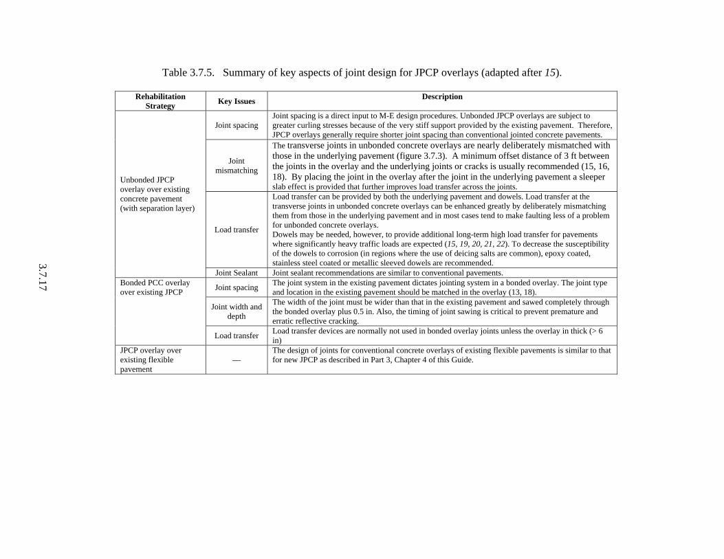
Rehabilitation Strategy Key Issues Description
Joint spacing Joint spacing is a direct input to M-E design procedures. Unbonded JPCP overlays are subject to greater curling stresses because of the very stiff support provided by the existing pavement. Therefore, JPCP overlays generally require shorter joint spacing than conventional jointed concrete pavements.
Joint mismatching
The transverse joints in unbonded concrete overlays are nearly deliberately mismatched with those in the underlying pavement (figure 3.7.3). A minimum offset distance of 3 ft between the joints in the overlay and the underlying joints or cracks is usually recommended (15, 16, 18). By placing the joint in the overlay after the joint in the underlying pavement a sleeper slab effect is provided that further improves load transfer across the joints.
Load transfer
Load transfer can be provided by both the underlying pavement and dowels. Load transfer at the transverse joints in unbonded concrete overlays can be enhanced greatly by deliberately mismatching them from those in the underlying pavement and in most cases tend to make faulting less of a problem for unbonded concrete overlays. Dowels may be needed, however, to provide additional long-term high load transfer for pavements where significantly heavy traffic loads are expected (15, 19, 20, 21, 22). To decrease the susceptibility of the dowels to corrosion (in regions where the use of deicing salts are common), epoxy coated, stainless steel coated or metallic sleeved dowels are recommended.
Unbonded JPCP overlay over existing concrete pavement (with separation layer)
Joint Sealant Joint sealant recommendations are similar to conventional pavements.
Joint spacing The joint system in the existing pavement dictates jointing system in a bonded overlay. The joint type and location in the existing pavement should be matched in the overlay (13, 18).
Joint width and depth
The width of the joint must be wider than that in the existing pavement and sawed completely through the bonded overlay plus 0.5 in. Also, the timing of joint sawing is critical to prevent premature and erratic reflective cracking.
Bonded PCC overlay over existing JPCP
Load transfer Load transfer devices are normally not used in bonded overlay joints unless the overlay in thick (> 6 in)
JPCP overlay over existing flexible pavement
— The design of joints for conventional concrete overlays of existing flexible pavements is similar to that for new JPCP as described in Part 3, Chapter 4 of this Guide.
Table 3.7.5. Summary of key aspects of joint design for JPCP overlays (adapted after 15).
3.7.17

3 ft
JPCP Overlay
Intact existing PCC
3 ft
JPCP Overlay
Intact existing PCC
Figure 3.7.3. Joint mismatching of unbonded concrete overlays (15). Sealant Type. Sealant type is used to estimate joint spalling (hence, smoothness). The sealant options available are liquid, silicone, and preformed. For restored JPCP, the sealant type is either that in the joints (if it is in good condition) or the sealant used for resealing the joints as part of restoration. For both bonded PCC over JPCP overlays and unbonded JPCP overlays, the appropriate sealant type (liquid, silicone, or preformed) is that specified. It must be noted that the type of sealant used could also affect the amount of surface infiltration into the pavement system, which is a user input. Edge Support Key design features that define edge support include the following:
• Shoulder type such as the use of tied PCC shoulders or hot mix AC shoulder. • Erodibility of the underlying base materials. • The use of widened slab or otherwise.
These are considered directly in the design process and are discussed below. Note that for widened slab (JPCP transverse cracking analysis) the applicable critical edge support is the centerline (lane to lane) joint, which is fixed in the analysis at a long-term load transfer efficiency (LTE) of 50 percent. Cracks will initiate from this lane to lane joint. Shoulder Type. Existing JPCP and JPCP overlays can be designed successfully with a variety of shoulder types and designs. The shoulder type selected in design affects both construction cost and pavement performance. The following options are available:
• Untied shoulders (e.g., hot mix AC, PCC, granular, or other shoulder types). • Tied PCC shoulders. • Widened slabs.
3.7.18

If tied concrete shoulders are used with the JPCP overlay, the long-term LTE between the lane and shoulder needs to be input. The LTE is defined as the ratio of deflections of the unloaded and loaded slabs. Typical long-term LTE values for JPCP range from:
• 50 to 70 percent—for monolithically constructed tied-PCC shoulder. • 30 to 50 percent—for separate lane and tied PCC shoulder construction.
Other shoulder types provide relatively little long-term LTE. For the lane-to-lane (centerline) joint, LTE depends on whether it is tied or untied and the amount of aggregate interlock present. For this design procedure, lane-to-lane long-term LTE is set at 50 percent (assumes a tied longitudinal joint). The amount of moisture infiltration into the pavement structure is also directly related to the shoulder type, as discussed in PART 3, Chapter 4. For existing JPCP subjected to restoration, the shoulder type typically remains the same as that of the existing pavement as determined during pavement evaluation. However, if the shoulder is replaced or retrofitted with a tied PCC shoulder, then the new shoulder type must be input for the design. Base Erodibility. The potential for base or subbase erosion (layer directly beneath the PCC layer) has a significant impact on PCC slab support and on the initiation and propagation of pavement distress. Different base types have different long-term erodibility behavior and are classified accordingly:
• Class 1—extremely erosion resistant materials. • Class 2—very erosion resistant materials. • Class 3—erosion resistant materials. • Class 4—fairly erodible materials. • Class 5—highly erodible materials.
Rigorous definitions of the material types that qualify under these various categories are provided in PART 2, Chapter 2. For restored JPCP and bonded PCC over existing JPCP, the base layer is considered as the layer immediately underlying the existing PCC layer. For unbonded JPCP overlays, the separator layer is considered the base layer except in situations where separator layers are not used (or is a thin fabric material), in which case the existing PCC layer is considered the base layer. PCC-Base Interface Properties The interface between the base and PCC slab can be modeled as follows:
• Completely bonded (for a specified user input time period). • Completely unbonded.
The bonding condition of the PCC and base impacts the structural responses in the PCC slabs and therefore affects the distress prediction. Bonded layers typically produce lower strains than unbonded layers. Asphalt, cement-stabilized, and other stabilized layers are more likely to be
3.7.19

bonded to the slab, at least initially. However, even for these layers, interface bonding gets weakened with time due to the effect of traffic and moisture, and the pavement behaves like an unbonded system, particularly around the edges. The design procedure therefore allows users to define when a bonded PCC slab/base interface is expected to become unbonded. Typical values for this input, Nbond, (the number of months before the interface becomes unbonded) are provided below:
• If the slab is to be analyzed as bonded to the stabilized base throughout the design life, Nbond = design life (applicable to JPCP/CRCP overlays of existing flexible pavements only).
• If the slab is to be analyzed as unbonded from the stabilized base throughout the design life, Nbond = 0 (applicable to unbonded and bonded overlays and JPCP restoration).
• If the slab is to be analyzed as debonding from stabilized base after N years, Nbond = N. Typical estimates values for N ranges from 1 to 10 years (applicable to JPCP/CRCP overlays over existing flexible pavements only).
Subsurface Drainage Features The current state of the art indicates that restored JPCP, existing JPCP overlaid with bonded PCC, and unbonded JPCP over existing pavements can be retrofitted with subsurface drainage facilities to improve upon pavement performance. This is especially true for pavements subjected to moisture damage. The facilities available, however, are limited to egdedrains, outlets, side ditches, and other supporting structures. PART 3, Chapter 1 describes a systematic approach for drainage considerations for rehabilitated pavements. PART 2, Chapter 5 and PART 3, Chapter 5 also describe a systematic approach for determining the adequacy of existing drainage facilities prior to rehabilitation and feasible rehabilitation alternatives for existing pavements with moisture-induced damage. The following steps summarize the detailed discussion presented in these chapters:
1. Assess the need for subsurface drainage. 2. If drainage is required, select viable drainage alternatives. 3. Perform hydraulic design of the drainage components. 4. Prepare pavement cross-section with appropriate drainage details for structural design. 5. Perform structural design.
CRCP Design Features CRCP is used in rehabilitation as an unbonded overlay or where a bonded PCC overlay is placed on top of an existing CRCP. Refer to PART 3, Chapter 4 for a detailed coverage of inputs and outputs.
3.7.20

Shoulder Type Refer to an earlier for the discussion on shoulder type selection for JPCP. Widened slabs are not directly considered for CRCP. An indirect approach to considering widened slabs, if desired, is presented in Part 3, Chapter 4. Permanent Curl/Warp Effective Temperature Difference Refer to an earlier section for the discussion on permanent curl/warp effective temperature difference selection. Steel Reinforcement Typically, the 0.625-in and 0.75-in diameter deformed bars are used for longitudinal reinforcement in CRCP. The choice of these bar diameters for the typical CRCP slab with a thickness ranging from 7 to 12 in results in a percent steel content ranging from 0.6 to 0.75. Typically, depth of concrete above the longitudinal steel bars ranges from 3.5-in to mid-depth. This value is a design input and has an effect on crack width (higher steel tighter cracks). Base Properties Erodibility Index. Refer to an earlier section for the discussion on base erodibility index selection. A hot mix AC separator layer of high quality would normally be given a rating of 1 for an unbonded overlay. PCC Slab/Base Friction. The friction between the CRCP overlay slab and underlying layer plays an important role in the development of proper crack spacing. For most situations, a moderate level of PCC slab/underlying layer friction is required. Some States use materials such as polyethylene sheeting as bond breakers to reduce PCC slab/underlying layer friction. This is not recommended since many State highway agencies have reported rideability and construction problems when CRCP was constructed on polyethylene sheeting. For this Guide, the CRC overlay slab/underlying layer friction is characterized by a factor (F) ranging from 1 to 20. Guidance on the selection of the CRC overlay slab/underlying layer friction is provided in PART 3, Chapter 4. A value of approximately 7.5 is recommended for an AC separator layer. Crack Spacing User Input (Mean Crack Spacing). The design procedure allows designers to input directly estimates of mean crack spacing. For unbonded CRCP overlays over existing pavements, the crack spacing properties required may be estimated based on local experience assuming that similar designs exist in the area. For bonded PCC over existing CRCP, the mean crack spacing is the same as that of the existing pavement. An estimate must be obtained as part of a pavement evaluation and distress survey as described in PART 2, Chapter 5. Estimate from Model. The design procedure also allows designers to estimate mean crack spacing using empirical models. This is the recommended approach as this prediction procedure
3.7.21

has shown good results. Designers have the option to modify the model coefficients based on local experience. A description of the model is presented in PART 3, Chapter 4. The friction coefficient has a major effect on crack spacing and also on crack width. Drainage and Surface Properties Information required under this category includes:
• Pavement surface layer (PCC) shortwave absorptivity. • Potential for infiltration. • Pavement cross slope. • Length of drainage path.
A description of the input data is presented in PART 3, Chapter 4. Layer Definition and Material Properties Layer Number and Description Figures 3.7.4 through 3.7.7 present the typical structure of a restored JPCP, bonded PCC over JPCP or CRCP, and JPCP/CRCP overlays. A description of the structures is presented in the following sections. For this Guide, pavement layers are assigned numbers beginning with 1 as the topmost layer.
Existing PCC Pavement
Subbase_n
Existing PCC Pavement
Base/subbase_1
Subgrade
Existing PCC Pavement
Subbase_n
Existing PCC Pavement
Base/subbase_1
Subgrade
Figure 3.7.4. Typical structure of an existing JPCP subjected to CPR.
3.7.22

Subbase_n
Existing intact or fractured PCCComposite AC/PCC
Base/subbase_1
Subgrade
Separator layer
JPCP/CRCP overlay
Subbase_n
Existing intact or fractured PCCComposite AC/PCC
Base/subbase_1
Subgrade
Separator layer
JPCP/CRCP overlay
Figure 3.7.5. Typical structure of an unbonded concrete overlay over an existing rigid pavement.
Subbase_n
Existing JPCP/CRCP
Base/subbase_1
Subgrade
PCC overlay
Bonding interface
Subbase_nSubbase_n
Existing JPCP/CRCP
Base/subbase_1
Subgrade
Existing JPCP/CRCP
Base/subbase_1
Subgrade
PCC overlay
Bonding interface
Figure 3.7.6. Typical structure of a bonded concrete overlay over an existing rigid pavement.
3.7.23

Existing HMAC Layer
Base
Subgrade
JPCP/CRCP Overlay
Interface
JPCP/CRCP Overlay
Interface
Existing HMAC Layer
Base
Subgrade
JPCP/CRCP Overlay
Interface
JPCP/CRCP Overlay
Interface
Figure 3.7.7. Typical structure of a concrete overlay over an existing hot mix AC pavement. The maximum number of layers that can be analyzed by the analysis module is 20. This refers to the total number of sub-layers within the pavement structure, including any sub-layering done internally by the program. Additional information has been presented in Part 3, Chapter 4. JPCP Restoration (CPR) Figure 3.7.4 shows an example of the structure of a restored JPCP and has the following component layers:
• Layer 1—the existing JPCP surface (to be restored). • Layer 2—a stabilized or unstabilized base/subbase (if it exists, it is considered the base in
design structural and non structural analysis). • Layer n-1—a stabilized or unstabilized subbase (if it exists). • Layer n—the subgrade/bedrock.
Unbonded JPCP/CRCP Overlay over Existing PCC Pavement Figure 3.7.5 shows an example of an unbonded JPCP or CRCP overlay over an existing rigid pavement. It has the following layers:
• Layer 1—JPCP or CRCP overlay. • Layer 2—Separator layer (typically new hot mix AC layer but could also be the existing
hot mix AC overlay of a composite AC/PCC pavement. It is considered the base in structural and non-structural analysis).
• Layer 3—the existing PCC pavement (considered the base in structural analysis only unless there is no separator layer where it is considered the base in all types of analysis).
• Layer 4—a stabilized or unstabilized subbase. • Layer n-1—a stabilized or unstabilized subbase. • Layer n—the subgrade/bedrock.
3.7.24

Bonded PCC Overlay over Existing JPCP/CRCP Figure 3.7.6 shows an example of a bonded PCC overlay over an existing JPCP or CRCP. It has the following layers:
• Layer 1—PCC overlay (bonded to the existing JPCP/CRCP layer). • Layer 2—Existing JPCP/CRCP layer. • Layer 3—a stabilized or unstabilized subbase (considered the base in structural and non
structural analysis). • Layer n-1—a stabilized or unstabilized subbase. • Layer n—the subgrade/bedrock.
JPCP/CRCP Overlay over Existing Flexible Pavement Figure 3.7.7 shows the structure of a JPCP or CRCP overlay over an existing flexible pavement. It has the following layers:
• Layer 1—the new JPCP/CRCP overlay. • Layer 2—the hot mix AC layer of the existing flexible pavement (considered the base in
structural and non structural analysis). • Layer 3—a stabilized or unstabilized base/subbase. • Layer n-1—a stabilized or unstabilized subbase. • Layer n—the subgrade/bedrock.
If bedrock is present within 10 ft of the pavement surface, it will influence the structural response of pavement layers and needs to be considered. Information required for characterizing the bedrock and procedures for doing so is presented in this chapter and in PART 2, Chapters 2 and 5 and PART 3, Chapter 4. However, in most design situations, the effect of bedrock is negligible since it is located deep below the pavement structure (if present at all) and does not need to be included in analysis. Note that the design procedure allows designers to define up to 10 layers, including the subgrade/bedrock. Layer Material Type A detailed description of the layer material types are presented in this section. The material described includes: • JPC or CRC (PCC) slab. • Asphalt-stabilized materials. • Chemically stabilized materials (e.g., lime, cement, flyash mixtures). • Unbound materials (e.g., AASHTO or Unified classifications of subgrade soils, crushed
stone, crushed gravel, and bedrock). Generally, paving materials are characterized using different kind of properties obtained through laboratory and field testing. PART 2, Chapter 2 of this guide provides a detailed description of the types of tests used in material characterization and the significance of each test
3.7.25

3.7.26
recommended. The relevant test standards and guidelines are also presented as part of the discussion. Layer Material Properties Layer material properties are categorized according the layer material type. The following is a description of the information required for layer material characterization. PCC Materials (Typically, Surface Layer) For rehabilitated pavements with PCC, the topmost layer is constructed with PCC as follows:
• Existing JPCP surface layer subjected to CPR. • Bonded PCC overlays over an existing JPCP or CRCP. • Unbonded JPCP or CRCP overlay over an existing flexible or rigid pavement.
The information required for characterizing the PCC surface layer material is summarized in tables 3.7.6 through 3.7.9. The layer properties listed in the tables may be obtained through laboratory and field testing or from historical records as described in PART 2, Chapters 2 and 5 and in PART 3, Chapter 4. Base/Subbase/Subgrade/Bedrock (Foundation) Layers For rehabilitated pavements, the foundation layers are defined as any of the following: • Existing PCC layer (for unbonded JPCP or CRCP overlays). • Existing hot mix AC layer (for JPCP or CRCP overlays). • New or existing separator layer (for unbonded JPCP or CRCP overlays or existing composite
or rigid pavements). • All other existing layers stabilized or unstabilized underlying the existing PCC surface layer
(underlying PCC/existing PCC for bonded overlays) down to the subgrade/bedrock. • Existing subgrade/bedrock. The information required for characterizing base, subbase, subgrade/bedrock material properties and layer thicknesses is summarized in tables 3.7.10 through 3.7.3.16. The information required is obtained through coring and testing of the existing pavement during pavement evaluation as described in PART 2, Chapters 2 and 5 for Level 1 data. Level 3 data is obtained for agency records.

3.7.27
Table 3.7.6. CPR or overlay concrete (layer 1) thermal properties and general data required for trial design.
Hierarchical Level Category Input Data 1 2 3
Unit weight Obtained from coring and laboratory testing (CPR) Laboratory testing (overlays) N/A
Estimate from historical agency or published data (all) General
Poisson’s ratio Obtained from coring and laboratory testing (CPR) Laboratory testing (overlays) N/A
Estimate from historical agency or published data (all)
Coefficient of thermal expansion
Obtained from coring and laboratory testing (CPR) Laboratory testing (overlays)
Estimate (based on mix constituents)
Estimate from historical agency or published data (all)
Thermal conductivity N/A1 N/A
Estimate from historical agency or published data (all)
Thermal properties
Heat capacity N/A N/A Estimate from historical agency or published data (all)
1No widely acceptable test procedure available.
Table 3.7.7. CPR or overlay concrete (layer 1) mix properties required for trial design.
Hierarchical Level Category Input Data 1 2 3Ultimate shrinkage (at 40 percent humidity)
Laboratory testing (applicable only for overlays)
Estimate (from correlation equation)
Estimate from historical agency or published data (all)
Reversible shrinkage (percent of ultimate shrinkage) N/A N/A Estimate from historical
agency or published data (all) Time to develop 50 percent of ultimate shrinkage
Determine from laboratory test data N/A Estimate from historical
agency or published data (all) Cement type Cement content Water-to-cement ratio Coarse aggregate type Concrete zero-stress temperature1
Mix
Curing method
Hierarchical levels not applicable. Data obtained from agency mix specifications (for overlays) and from historical agency data (for CPR)
1The design software allows designers to estimate PCC zero-stress temperature from models using PCC mix properties and construction monthly temperature.

3.7.28
Table 3.7.8. CPR or overlay (layer 1) thickness data required for trial design.
Parameter1 Rehabilitation Strategy
Level of Input Description
1
• Inputs are obtained through nondestructive testing such as GPR as described in Part 2, Chapter 5
• Inputs are obtained through coring the slab and measuring layer thicknesses as described in Part 2, Chapters 2 and 5
• Minimum thickness for the existing PCC layer for JPCP and CRCP are 6- and 7-in, respectively
CPR
3 Inputs are obtained from as-constructed plans (minimum thickness for existing JPCP and CRCP PCC layer are 6- and 7-in, respectively)
Bonded overlays1 1, 2, 3 A trial overlay thickness must be assumed (typically from 2 to 5 in) and used in design (minimum combined thickness for the exiting PCC layer and overlay for JPCP and CRCP are 6- and 7-in, respectively)
Layer thickness
Unbonded overlays and
PCC/AC 1, 2, 3 A trial overlay thickness must be assumed (minimum thickness for JPCP and
CRCP overlays are 7-in) 1Overlay and existing PCC are combined to form a composite PCC layer for design analysis.

Table 3.7.9. CPR and overlay concrete (layer 1) strength data required for trial design.
Parameter1 Rehabilitation Strategy
Level of Input Description
1
Inputs are obtained through cutting beams from the slab and testing samples for long-term elastic modulus, flexural strength, and tensile strength as described in Part 2, Chapters 2 and 5. The data is assumed to be the long-term strength and is therefore constant throughout rehabilitation design life
2
Inputs are obtained through coring the slab and testing cored samples for long-term compressive strength as described in Part 2, Chapters 2 and 5 (models are used to convert the compressive strength to flexural strength, tensile strength, and elastic modulus
Restoration (CPR)1,2
3
Inputs are 28-day compressive strength or 28-day flexural strength obtained from historical records or estimated. If the 28-day PCC elastic modulus is available from historical records it can also be input along with either of the strength parameters referenced above otherwise it is computed from standard correlation (see PART 2, Chapter 2)
Bonded overlays of existing PCC
(Overlay) 1, 2, 3 Utilize the recommendations for unbonded overlays.
Bonded overlays of existing PCC (Existing PCC)
1, 2, 3 Utilize the recommendations for restoration.
1
• 7-, 14-, 28-, 90-day elastic modulus (JPCP and CRCP), flexural strength (JPCP and CRCP) and tensile strength (CRCP)
• 20-yr to 28-day strength ratio for elastic modulus (JPCP and CRCP), flexural strength (JPCP and CRCP) and tensile strength (CRCP)
2 • 7-, 14-, 28-, 90-day compressive strength (JPCP and CRCP) • 20-yr to 28-day strength ratio (JPCP and CRCP)
PCC strength (layer 1)
Unbonded overlays and
PCC/AC
3 • 28-day flexural strength and elastic modulus • 28-day compressive strength and elastic modulus
1Level 1 EC can also be obtained by backcalculation (using FWD deflection data and layer thicknesses) and multiplying by 0.8 to convert from dynamic to static for existing pavements subjected to CPR. 2For restored pavements, PCC strength at the time of restoration is used in design. The PCC strength throughout CPR design life is assumed constant.
3.7.29
3.7.30
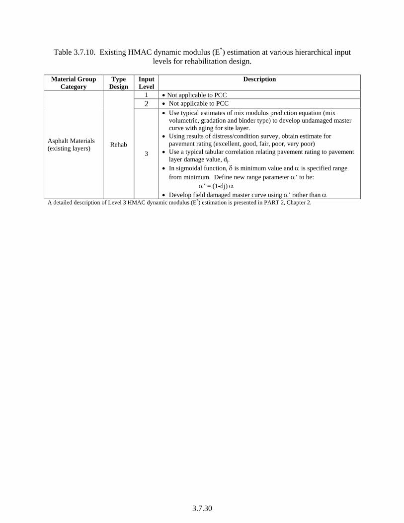
Table 3.7.10. Existing HMAC dynamic modulus (E*) estimation at various hierarchical input levels for rehabilitation design.
Material Group
Category Type
Design Input Level
Description
1 • Not applicable to PCC 2 • Not applicable to PCC
Asphalt Materials (existing layers) Rehab
3
• Use typical estimates of mix modulus prediction equation (mix volumetric, gradation and binder type) to develop undamaged master curve with aging for site layer.
• Using results of distress/condition survey, obtain estimate for pavement rating (excellent, good, fair, poor, very poor)
• Use a typical tabular correlation relating pavement rating to pavement layer damage value, dj.
• In sigmoidal function, δ is minimum value and α is specified range from minimum. Define new range parameter α’ to be:
α’ = (1-dj) α • Develop field damaged master curve using α’ rather than α
A detailed description of Level 3 HMAC dynamic modulus (E*) estimation is presented in PART 2, Chapter 2.

Table 3.7.11. Data required for characterizing existing PCC slab and chemically stabilized layers.
3.7.31
Hierarchical Level Input Data11 2 3
Unit weight Obtained from coring and testing N/A Estimate from historical agency data
Poisson’s ratio Obtained from coring and testing N/A Estimate from historical agency data (see Part 2, Chapter 2)
Existing PCC slab design elastic modulus (applicable in situations where the existing intact PCC slab is considered the base)2
The test elastic modulus ETEST is obtained from (1) coring the intact slab and laboratory testing for elastic modulus or (2) by backcalculation (using FWD deflection data from intact slab and layer thicknesses) and multiplying by 0.8 to convert from dynamic to static modulus. The design existing PCC slab elastic modulus is determined as follows: EBASE/DESIGN = CBD*ETEST where ETEST is the static elastic modulus obtained from coring and laboratory testing or backcalculation of uncracked intact slab concrete and CBD is a factor based on the overall PCC condition as follows: • CBD = 0.42 to 0.75 for existing pavement in overall “good” structural
condition. • CBD = 0.22 to 0.42 for existing pavement in “moderate” condition. • CBD = 0.042 to 0.22 for existing pavement in “severe” condition Pavement condition is defined in table 3.7.12. A maximum EBASE/DESIGN of 3 million psi is recommended due to existing joints even if few cracks exist.
EBASE/DESIGN obtained from coring and testing for compressive strength. The compressive strength value is converted into elastic modulus as outlined in Part 2, Chapter 2. The design elastic modulus is obtained as described for level 1
EBASE/DESIGN estimated from historical agency data and local experience for the existing project under design
Rubblized PCC (applicable in situations where the existing intact PCC slab is considered the base)2
N/A N/A
EBASE/DESIGN typically ranges from 50,000 to 150,000 psi. It could also be estimated from historical agency data and local experience
Chemically stabilized materials elastic modulus
Obtained from coring and testing for elastic modulus as outlined in Part 2, Chapter 2
Obtained from coring and testing for compressive strength. The compressive strength value is converted into elastic modulus as outlined in Part 2, Chapter 2.
Estimated from historical agency data and local experience
Thermal conductivity N/A N/A Estimate from historical data Heat capacity N/A N/A Estimate from historical data
1Detailed descriptions of test procedure used t obtain the input data required are presented in PART 2, Chapter 2. 2Note that the CBD factors and the factor (0.8) for converting dynamic to static EPCC are those recommended in this Guide. Designer may modify these factors since the modified modulus is the input parameter required by the design software.

3.7.32
Table 3.7.12. Description of existing PCC pavement condition.
1Percent slabs cracked with all severities and types of cracks plus any repairs. 2Percent area including repairs or patches, deteriorated joints, and deteriorated cracks (deteriorated joints and cracks converted to repair areas). 3Percent area includes repairs, patches, and localized failures and punchouts converted to repair areas.
Structural Condition Existing Pavement Type Good Moderate Severe Rubblized
JPCP (percent slabs cracked)1 <10 10 to 50 > 50 or crack
and seat Rubblized
JRCP (percent area deteriorated)2 < 5 5 to 25 > 25 percent or
break and seat Rubblized
CRCP (percent area deteriorated)3 < 3 3 to 10 > 10 Rubblized

3.7.33
Table 3.7.13. Information required for characterizing pavement effective dynamic (not traditional static) modulus of subgrade reaction for rehabilitation design.
Input Data Hierarchical Level Description
1
There is no laboratory testing procedure for resilient modulus available for level 1 for rigid pavements. Level 1 modulus of subgrade reaction is determined by backcalculating the effective modulus of subgrade reaction (for the existing pavement) using FWD deflection test data as outlined in PART 2, Chapter 5 on the existing slab. For backcalculation, the input is deflections, which are then used to backcalculate modulus of subgrade reaction using any appropriate layer moduli backcalculation algorithm. The mean project backcalculated modulus of subgrade reaction obtained after backcalculation for a given month is the input required by the Design Guide software. Moduli of subgrade reaction values for the remaining months of the year are determined by letting the EICM compute seasonal adjustment factors (for those months) and using the seasonal adjustment factors to estimate modulus of subgrade reaction for the remaining months.
2
Determine the resilient modulus of each foundation layer underlying the PCC surface (e.g., base, subbases and subgrade) by running field tests for DCP (for a given month) or laboratory analysis of bulk samples obtained from the existing pavement for CBR, R-Value, or AASHTO soil classification and transforming them into resilient modulus through models/correlations.1, 2
The seasonal resilient modulus is determined by: (1) Enter the resilient modulus at optimum water content and let the EICM do the seasonal adjustments, (2) Entering 12 resilient moduli (one for each month) or (3) Enter 1 representative resilient modulus and this will be used throughout the year. The resilient moduli are then transformed into an effective modulus of subgrade reaction value using procedures outlines in PART 3, Chapter 4.
Modulus of subgrade reaction
(dynamic from FWD
back-calculation,
approx. twice static)
3
Regional or typical values are assumed from historical agency data for design. Seasonal values are determined as follows: (1) Enter the resilient modulus at optimum water content and let the EICM do the seasonal adjustments or (2) Enter 1 representative resilient modulus to be used for all seasons. The resilient moduli are then transformed into an effective modulus of subgrade reaction value using procedures outlines in PART 3, Chapter 4.
1Procedures used to obtain unbound granular material, subgrade soil, and bedrock layer material moduli are presented in table 3.7.14. Hot mix AC and chemically stabilized material layer moduli can be estimated using procedures outlined in tables 3.7.10 and 3.7.11. 2 Level 2 requires testing of a soil sample using some test such as CBR or R-value and then estimating the layer resilient modulus using a prediction equation. Level 3 requires estimation using a correlation from soil classification such as AASHTO or UCS. A guide for selecting an appropriate Level 3 resilient modulus is provided in PART 2, Chapter 2. Note that whenever a granular subgrade exists, the recommended resilient modulus is fairly high and if this subgrade layer is not truly infinite in depth, will result in overestimation of the subgrade support and a very high backcalculated k value (see section titled “Computation of Effective k-value”). If the stiffer granular layer is relatively thin (e.g., less than 5 to 10 ft) then a reduction in the selected subgrade resilient modulus is warranted.

3.7.34
Table 3.7.14. Information required for characterizing unbound granular materials, subgrade soils, and bedrock resilient modulus.
Hierarchical Level Input Data 1 2 3
Resilient modulus
There is no laboratory testing procedure for resilient modulus available for level 1 rigid pavements. Level 1 rigid pavement rehabilitation parameter is deflection data obtained from FWD testing and used for backcalculation of modulus of subgrade reaction (Table 3.7.13)
Data is obtained by running field tests for DCP (for a given month) or laboratory testing of bulk samples obtained from the existing pavement for CBR, R-Value, and AASHTO soil classification. Resilient modulus is then estimated using models/correlations with the test values as input. The seasonal resilient moduli are determined by: (1) Entering the resilient modulus at optimum water content and let the EICM do the seasonal adjustments, (2) Enter 12 resilient moduli (one for each month), or (3) Enter 1 representative resilient modulus and this will be used throughout the year.
Regional or typical values are assumed from historical agency data for design. Seasonal values are determined as follows: (1) Enter the resilient modulus at optimum water content and let the EICM do the seasonal adjustments, (2) Enter 1 representative resilient modulus value to be used for all seasons (no moisture content is required)

Hierarchical Level Input 1 2 3
Plasticity index Obtained through laboratory testing of bulk samples N/A Estimate from historical agency data Percent passing No. 200 sieve Obtained through laboratory testing of bulk samples N/A Estimate from historical agency data Percent passing No. 4 sieve Obtained through laboratory testing of bulk samples N/A Estimate from historical agency data Sieve size for with 60 percent of the subgrade material is retained (D60) Obtained through laboratory testing of bulk samples N/A Estimate from historical agency data
Dry thermal conductivity Obtained through testing of bulk samples N/A Estimate from historical agency data Dry heat capacity Obtained through testing of bulk samples N/A Estimate from historical agency data Unbound granular/soil material characteristic curve parameters (a, b, c, and hr)1
Obtained through laboratory testing of bulk samples N/A Estimate from historical agency data
1A detailed discussion on how to obtain unbound granular/soil material characteristic curve parameters and their significance has been presented in PART 2, Chapter 3.
Table 3.7.15. Description of sources of layer thickness data required for trial design.
Parameter Hierarchical Level of Input Description
1
• Inputs are obtained through nondestructive testing such as GPR as described in PART 2, Chapter 5
• Inputs are obtained through coring the layer and measuring the thickness as described in PART 2, Chapters 2 and 5
Base, subbase layer thickness
3 Inputs are obtained by estimating layer thickness from as-constructed plans
1Applicable to hot mix AC or asphalt stabilized, PCC or chemically stabilized, and unbound base or subbase layers.
Table 3.7.16. Additional information required for unbound granular material, unbound soil material, subgrade,/bedrock (used in EICM)
3.7.35
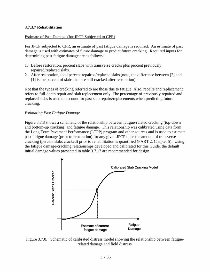
3.7.3.7 Rehabilitation Estimate of Past Damage (for JPCP Subjected to CPR) For JPCP subjected to CPR, an estimate of past fatigue damage is required. An estimate of past damage is used with estimates of future damage to predict future cracking. Required inputs for determining past fatigue damage are as follows: 1. Before restoration, percent slabs with transverse cracks plus percent previously
repaired/replaced slabs. 2. After restoration, total percent repaired/replaced slabs (note, the difference between [2] and
[1] is the percent of slabs that are still cracked after restoration). Not that the types of cracking referred to are those due to fatigue. Also, repairs and replacement refers to full-depth repair and slab replacement only. The percentage of previously repaired and replaced slabs is used to account for past slab repairs/replacements when predicting future cracking. Estimating Past Fatigue Damage Figure 3.7.8 shows a schematic of the relationship between fatigue-related cracking (top-down and bottom-up cracking) and fatigue damage. This relationship was calibrated using data from the Long Term Pavement Performance (LTPP) program and other sources and is used to estimate past fatigue damage (prior to restoration) for any given JPCP once the amount of transverse cracking (percent slabs cracked) prior to rehabilitation is quantified (PART 2, Chapter 5). Using the fatigue damage/cracking relationships developed and calibrated for this Guide, the default initial damage values presented in table 3.7.17 are recommended for design.
Fatigue Damage
Estimate of current fatigue damage
Per
cent
Sla
bs C
rack
ed
Calibrated Slab Cracking Model
Fatigue Damage
Estimate of current fatigue damage
Per
cent
Sla
bs C
rack
ed
Fatigue Damage
Estimate of current fatigue damage
Per
cent
Sla
bs C
rack
ed
Calibrated Slab Cracking Model
Figure 3.7.8. Schematic of calibrated distress model showing the relationship between fatigue-related damage and field distress.
3.7.36

Table 3.7.17. Recommended total fatigue damage used in design analysis (estimated from calibrated slab fatigue damage and cracking relationship).
Distress (Percent Slabs
Cracked) Total Fatigue Damage
0 0.100 to 0.250 10 0.270 20 0.438 30 0.604 40 0.786 50 1.000
The estimated total fatigue damage is used internally in the design software to estimate the proportion of total fatigue damage due to bottom-up and top-down cracking as follows:
1. Determine future fatigue damage estimates (total, top-down, and bottom-up fatigue damage).
2. Compute the percentage of total fatigue damage due to top-down and bottom-up damage mechanism (e.g., 45 percent top-down and 55 percent bottom-up fatigue damage).
3. Use the computed percentage to divide past total fatigue damage (shown in table 3.7.17) into the amounts due to top-down and bottom-up mechanism.
The effect of existing PCC pavement past damage on bonded PCC over existing JPCP/CRCP is negligible and therefore not considered in design. For unbonded JPCP or CRCP overlays over existing rigid pavement, PCC damage in existing slab is considered as outlined in tables 3.7.11 and 3.7.12, while for JPCP or CRCP overlays over existing flexible pavement hot mix AC damage is considered as outlined in table 3.7.10. Dynamic Modulus of Subgrade Reaction As presented in table 3.7.13, pavement foundation strength is estimated using an effective dynamic modulus of subgrade reaction value. The effective modulus of subgrade reaction is estimated by computing the monthly resilient/elastic moduli of each layer, including the bedrock (if the depth to bedrock if less than 10 ft), and subsequently converting them into a single effective dynamic modulus of subgrade reaction (dynamic k-value). The effective dynamic modulus of subgrade reaction, therefore, essentially represents the compressibility of underlying layers (i.e., unbound base, subbase, and subgrade layers) upon which the upper bound layers and existing hot mix AC or PCC layer is constructed. For reference, the dynamic k-value is approximately twice the traditional static k-value. Below is a brief description of the procedure for converting the layer moduli to an effective dynamic modulus of subgrade reaction. Conversion of Base, Subbase, and Subgrade Layers Resilient Moduli into Single Effective Dynamic Modulus of Subgrade Reaction (k-value) A comprehensive discussion is presented in PART 3, Chapter 4 on the conversion of base, subbase, and subgrade moduli into a single effective dynamic modulus of subgrade reaction.
3.7.37

For rehabilitation design, because the dynamic modulus of subgrade reaction is backcalculated from the PCC surface deflections, the result is an “effective” dynamic k-value that represents the compressibility of all layers beneath the PCC slab. Note that for rehabilitation with PCC, the PCC slab is defined based on the rehabilitation strategy adopted as follows:
• For restored JPCP, the PCC slab is defined as the existing PCC surface layer. • For unbonded JPCP/CRCP over existing rigid pavement, the PCC slab is defined as the
overlay PCC slab. • For bonded PCC over JPCP/CRCP, the PCC slab is the composite overlay/existing PCC
layer. • For JPCP/CRCP overlay over existing flexible pavements, the PCC slab is defined as the
overlay PCC slab. Also, if the pavement is constructed in a region with a bedrock layer that is close to the surface (< 10 ft), then the bedrock is entered as a stiff layer (high elastic modulus) beneath the subgrade soil layer (becomes the subgrade). The PCC surface deflections calculated using JULEA reflects the presence of the bedrock layer and, consequently, the bedrock layer is reflected in the calculated effective modulus of subgrade reaction. The effective dynamic k-value of the subgrade would be calculated by the EICM for each season (month) throughout the year and utilized directly to compute critical stresses and deflections in the incremental damage accumulation over the design life of the pavement. Its value is affected greatly by factors such as water table depth, depth to bedrock, and frost depth penetration. All of these are considered in the EICM. 3.7.4 JPCP REHABILITATION DESIGN This section describes the application of design procedures to evaluate rehabilitated JPCP trial designs for adequacy. JPCP rehabilitation design in this Guide is limited to the following:
• Restoration with CPR treatments (including diamond grinding) of existing JPCP. • Unbonded JPCP over existing rigid pavement of any type or composite pavement. • Bonded PCC over existing JPCP. • JPCP overlay over existing flexible pavements.
Pavements designed using these procedures are expected to carry significant levels of traffic. 3.7.4.1 Performance Criteria Performance criteria are definitions of the maximum amounts of individual distress or smoothness acceptable to the highway agency at a given reliability level. Performance indicators used for JPCP rehabilitation design are as follows:
• Transverse joint faulting. • Transverse cracking. • Smoothness (measured using IRI).
3.7.38

Performance criteria are a user input and depend on local agency design standards as described in section 3.7.3 of this chapter. 3.7.4.2 Design Reliability Deterministic analysis (which utilizes all mean input values) entails predicting the key performance indicators (pavement distresses and smoothness) at 50 percent reliability. In probabilistic analysis, the performance of the pavement in terms of the key performance indicators can be obtained at any desired level of reliability. Design reliability is described in section 3.7.3 of this chapter, PART 3, Chapter 4, and PART 1, Chapter 1. 3.7.4.3 Design Considerations A detailed description of the factors that affect transverse joint faulting, transverse cracking, and smoothness is presented in PART 3, Chapter 4. The information presented could also be applied to JPCP rehabilitation design. A summary of the factors that affect distress and smoothness are summarized in table 3.7.18. Of the factors listed, dowels tend to have the most influence on transverse joint faulting while slab thickness and CTE has the most influence on cracking. Dowels are used in JPCP to improve load transfer across transverse joints. Typically, round steel dowels are placed 12 in on center across a lane. The dowel diameter is typically selected as a function of the slab thickness, which in turn is a function of the design traffic loadings. Field performance of doweled joints using the typical spacing has been good. However, theoretical analysis suggests that the same performance can be expected with as few as three to four dowels per wheel path. In CPR (e.g., full-depth repairs and dowel bar retrofit of older concrete pavements) often only four dowel bars per wheel path are placed. These configurations have performed well under high volumes of traffic. Designers must note that the JPCP rehabilitation procedure presented is based on round steel dowels (with diameters varying from 1 to 1.5 in) placed on center across a lane with equal spacing between them across the entire transverse joint. The use of only four dowel bars per wheel path, therefore, cannot be analyzed exactly with this procedure. Also, site factors for which designers have no control such as climate (precipitation, freezing index, and number of freeze-thaw cycles, and particularly daytime (positive) temperature difference through the slab) and traffic should be considered when selecting design features. Finally, reducing specific distress has the added benefit of minimizing the rate of smoothness loss and hence these factors in an indirect manner also influence JPCP smoothness.
3.7.39
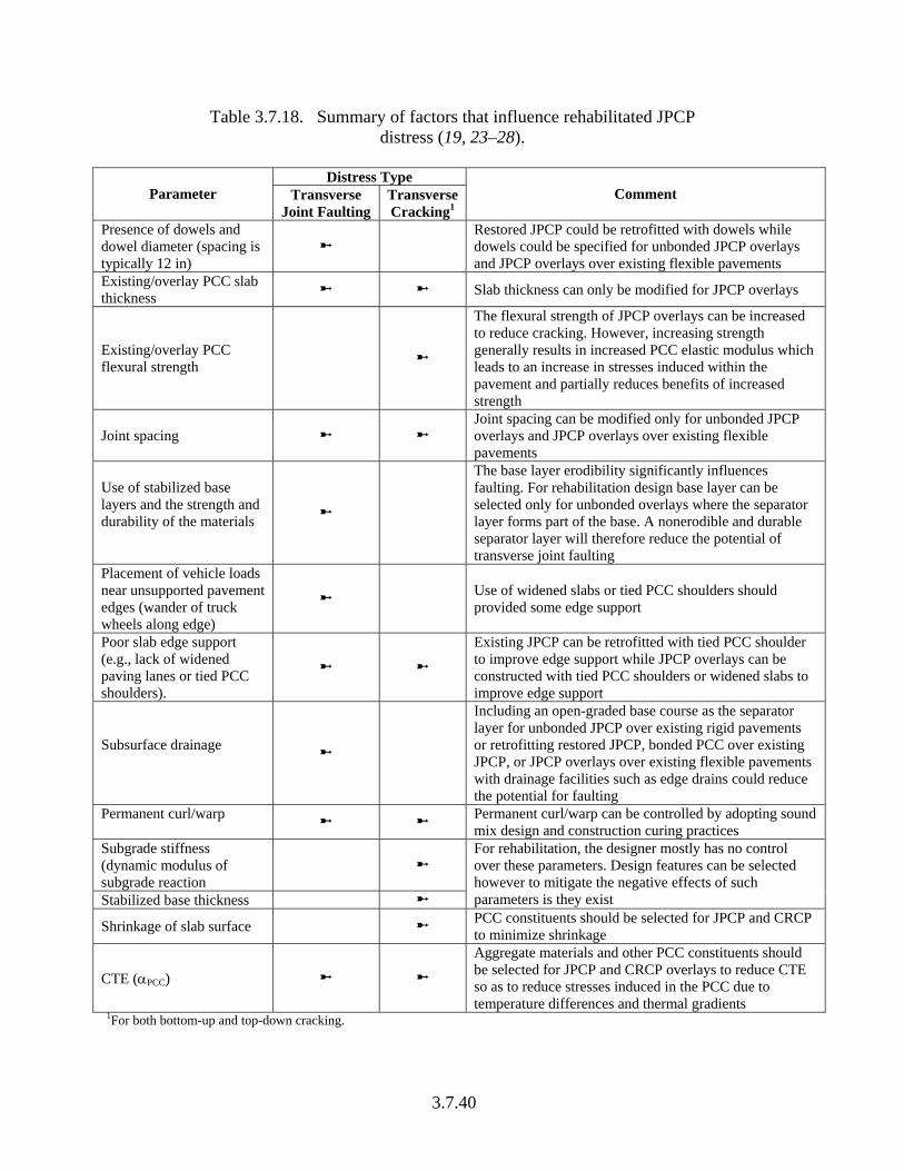
Table 3.7.18. Summary of factors that influence rehabilitated JPCP distress (19, 23–28).
Distress Type
Parameter Transverse Joint Faulting
Transverse Cracking1
Comment
Presence of dowels and dowel diameter (spacing is typically 12 in)
Restored JPCP could be retrofitted with dowels while dowels could be specified for unbonded JPCP overlays and JPCP overlays over existing flexible pavements
Existing/overlay PCC slab thickness Slab thickness can only be modified for JPCP overlays
Existing/overlay PCC flexural strength
The flexural strength of JPCP overlays can be increased to reduce cracking. However, increasing strength generally results in increased PCC elastic modulus which leads to an increase in stresses induced within the pavement and partially reduces benefits of increased strength
Joint spacing Joint spacing can be modified only for unbonded JPCP overlays and JPCP overlays over existing flexible pavements
Use of stabilized base layers and the strength and durability of the materials
The base layer erodibility significantly influences faulting. For rehabilitation design base layer can be selected only for unbonded overlays where the separator layer forms part of the base. A nonerodible and durable separator layer will therefore reduce the potential of transverse joint faulting
Placement of vehicle loads near unsupported pavement edges (wander of truck wheels along edge)
Use of widened slabs or tied PCC shoulders should provided some edge support
Poor slab edge support (e.g., lack of widened paving lanes or tied PCC shoulders).
Existing JPCP can be retrofitted with tied PCC shoulder to improve edge support while JPCP overlays can be constructed with tied PCC shoulders or widened slabs to improve edge support
Subsurface drainage
Including an open-graded base course as the separator layer for unbonded JPCP over existing rigid pavements or retrofitting restored JPCP, bonded PCC over existing JPCP, or JPCP overlays over existing flexible pavements with drainage facilities such as edge drains could reduce the potential for faulting
Permanent curl/warp Permanent curl/warp can be controlled by adopting sound
mix design and construction curing practices Subgrade stiffness (dynamic modulus of subgrade reaction
Stabilized base thickness
For rehabilitation, the designer mostly has no control over these parameters. Design features can be selected however to mitigate the negative effects of such parameters is they exist
Shrinkage of slab surface PCC constituents should be selected for JPCP and CRCP to minimize shrinkage
CTE (αPCC)
Aggregate materials and other PCC constituents should be selected for JPCP and CRCP overlays to reduce CTE so as to reduce stresses induced in the PCC due to temperature differences and thermal gradients
1For both bottom-up and top-down cracking.
3.7.40

3.7.4.4 Trial Rehabilitation Design The basic concept of rehabilitation design is first to select a trial design with defined layers, material types and properties, and relevant design features based on the future level of traffic anticipated. This is followed by the selection of the design performance criteria (used for evaluating the adequacy of the trial design), the desired level of reliability, and the determination of input data (see section 3.7.3 of this chapter). Next, the design software is used to process the input data. Data processing includes estimating climate related aspects such as pavement temperature profile for each hour within the design period using EICM and computing long-term PCC flexural strength. The processed data is then used to compute the pavement structural responses (stress, deflections) for each distress type and time incremental. Computed structural responses are used to estimate distress and hence smoothness. The trial rehabilitation design is then evaluated for adequacy using prescribed performance criteria at a given reliability level. Trial designs deemed inadequate are modified and reevaluated until a suitable design is achieved. Design modifications could range from making simple changes to thicknesses of layer materials and varying strength properties to adopting a new rehabilitation strategy altogether. It is recommended that such rehabilitation designs, though technically feasible, be subjected to a life cycle cost analysis and assessed for other factors before being adopted as recommended in PART 3, Chapter 5 and Appendix C. An outline of the JPCP rehabilitation design procedure for the rehabilitation strategies listed is presented in figure 3.7.9. A list of distress types/smoothness relevant for the design of the selected rehabilitation strategies is presented in table 3.7.19. Each rehabilitation strategy must be analyzed in detail to determine if it performs adequately over the expected rehabilitation period at a given reliability level. Detailed descriptions of the procedures for estimating transverse joint faulting, transverse cracking (bottom-up and top-down), and smoothness are presented in the following sections. The JPCP rehabilitation design procedure described allows for use for various rehabilitation strategies, including staged construction. As an example, the procedure can be used to design CPR treatments for a deteriorated JPCP for a limited time period (e.g., 6 years) before overlaying it. 3.7.4.5 Transverse Joint Faulting Transverse joint faulting is the differential elevation across the joint measured approximately 1 ft from the slab edge (longitudinal lane to shoulder joint for a conventional 12-ft lane width), or from the lane paint stripe for a widened slab. Since joint faulting varies significantly from joint to joint, the mean faulting of all transverse joints in a given project is the parameter predicted by the model used in this Guide for performance evaluation. Faulting is an important deterioration mechanism of JPCP because of its impact on ride quality. Joint faulting also has a major impact on the life cycle costs of rehabilitated pavements, both in terms of increased costs due to early failure of the rehabilitation strategy and on vehicle operating costs as faulting becomes severe. Transverse joint faulting is the result of a combination of, moving heavy axle loads, poor joint load transfer, free moisture beneath the PCC slab and or base, and base/subbase erosion (19, 24, 25).
3.7.41

•Existing cracking and repairs
•Construction data
•Combination of top -down and bottom up cracking
IRI•Initial IRI•Cracking, faulting, spalling•Subgrade/climate
Check predicted performance against design criteria at reliability level
Requirementssatisfied?
Design Complete
Select Trial Design•Layer thicknesses•Layer material properties•Shoulder
Performance Criteria•Cracking•Faulting•IRI
Reliability Level•Cracking•Faulting•IRI
Site Specific Inputs••Foundation•Traffic
Top-down Cracking•Calculate stresses•Calculate damage•Predict top-down cracking
Bottom-up Cracking•Calculate stresses•Calculate damage•Predict bottom-up cracking
Faulting•Calculate deflections•Calculate incremental faulting•Predict cumulative faulting
Total Percent Slabs Cracked•Combination of top -down and bottom up cracking
IRI•Initial IRI•Cracking, faulting, spalling•Subgrade/climate
Check predicted performance against design criteria at reliability level
Requirementssatisfied?
No
Design Complete
Yes
•Existing cracking and repairs
•Construction data
Climate
•Existing cracking and repairs
•Construction data
•Combination of top -down and bottom up cracking
IRI•Initial IRI•Cracking, faulting, spalling•Subgrade/climate
Check predicted performance against design criteria at reliability level
Requirementssatisfied?
Design Complete
Select Trial Design•Layer thicknesses•Layer material properties•Shoulder
Performance Criteria•Cracking•Faulting•IRI
Reliability Level•Cracking•Faulting•IRI
Site Specific Inputs••Foundation•Traffic
Top-down Cracking•Calculate stresses•Calculate damage•Predict top-down cracking
Bottom-up Cracking•Calculate stresses•Calculate damage•Predict bottom-up cracking
Faulting•Calculate deflections•Calculate incremental faulting•Predict cumulative faulting
Total Percent Slabs Cracked•Combination of top -down and bottom up cracking
IRI•Initial IRI•Cracking, faulting, spalling•Subgrade/climate
Check predicted performance against design criteria at reliability level
Requirementssatisfied?
No
Design Complete
Yes
•Existing cracking and repairs
•Construction data
Climate
Figure 3.7.9. Overview of JPCP rehabilitation design procedure.
3.7.42

Table 3.7.19. Summary of relevant distress/smoothness required for JPCP rehabilitation design.
Rehabilitation Strategy1 Feasible Treatments Pavement Type Performance Criteria
JPCP rehabilitation without overlays (CPR)
Diamond grinding with appropriate selection of:2
• Load transfer restoration • Full-depth repair • Slab replacement • Shoulder replacement • Subdrainage improvement
Existing JPCP (to be restored)
Faulting, transverse cracking, smoothness (IRI)
Preoverlay restoration and bonded PCC overlay over existing rigid pavement
JPCP overlay Faulting, transverse cracking, smoothness (IRI)
Preoverlay restoration and unbonded PCC overlay over existing rigid pavement
JPCP overlay Faulting, transverse cracking, smoothness (IRI)
Rehabilitation with overlays
Surface preparation and concrete overlay over existing flexible pavement
JPCP overlay Faulting, transverse cracking, smoothness (IRI)
Reconstruction Reconstruction with JPCP All Faulting, transverse cracking, smoothness (IRI)
1The design procedure for reconstruction of an existing pavement with JPCP is the same as that of new design and is presented in Part 3, Chapter 4. 2Diamond grinding is normally recommended to restore smoothness and the JPCP restoration procedure in this Guide assumes that diamond grinding is always performed. If diamond grinding is not utilized then this design procedure cannot be used to evaluate future performance (for joint faulting or IRI). Computing Structural Responses The pavement’s structural response of interest for JPCP faulting (applicable to both JPCP rehabilitation without overlays and rehabilitation with JPCP overlays) is the maximum corner deflection and corner differential deflection across the joint of the JPCP surface layer. It is computed for each time increment analyzed (for single, tandem, tridem, and quad axles) so damage can be computed incrementally. Maximum corner deflection and corner differential deflection across the joint are computed using several different types of input data, including:
• PCC properties (thickness, elastic modulus, Poisson’s ratio, unit weight, coefficient of thermal expansion, and ultimate shrinkage. Note that for restored JPCP and bonded PCC over existing JPCP the existing PCC slab is assumed to have achieved its ultimate shrinkage at the time of rehabilitation. Seasonal variations of shrinkage in these layers are considered in design.
• Base thickness and elastic modulus. Note that coefficient of thermal expansion of the base layer is assumed equal to the PCC coefficient of thermal expansion.
• PCC slab and base interface condition (an unbonded interface condition is assumed in all cases expect for JPCP overlays over existing flexible pavement were designer could assign a time typically ranging from 0 to 10 years when the PCC slab/base bonding is lost. Note that bonding between the JPCP overlay slab and existing hot mix AC layer is
3.7.43

dependent on the construction practices specified and implemented by the designer. If an unbonded interface between the PCC slab and the base is assumed the base unit weight is set to 0.
• Joint spacing. • Dynamic modulus of subgrade reaction. • Shoulder and transverse joint LTE (deflection LTE of the longitudinal lane-lane
(centerline) joint is assumed equal to 50 percent). Transverse joint LTE depends on several factors including base type and presence of dowels and dowel diameter.
• Permanent and transitory curl/warp characterized by the effective temperature difference (mean monthly nighttime values).
• Ambient relative humidity (seasonal in top of PCC slab). • Axle type (single, tandem, or tridem) and axle weight. • Axle position (distance from the critical slab edge). For transverse joint faulting analysis,
the critical wheel location is measured from the lane-shoulder interface of the PCC slab. The reference point for measurement is the lane paint stripe, regardless of whether the slab is widened or not.
An assumption of longitudinal lane-lane joint LTE of 50 percent is reasonable if the lane-lane joint is generally in good shape. Restoration of existing JPCP includes lane-to-lane joint repair (tied full-depth patching) for existing JPCP with severely deteriorated lane-lane joints or existing JPCP with severely deteriorated lane-lane joints are overlaid (unbonded overlay with thick separator layer). Also, for JPCP rehabilitation design, the definitions of PCC surface layer, base, subgrade, and so on differ according to the rehabilitation strategy (see figures 3.7.4 through 3.7.7), and this must be considered in assigning the appropriate values of design features and material properties. The design software computes structural responses (critical stresses and deflections in the pavement due to traffic loads and climatic effects) using rapid solution neural network (NN) models that are based on a finite element (FE) structural analysis. The neural network models were developed specifically for the rehabilitation strategies covered by this Guide. The NN were developed using a range of traffic loadings, site properties, and design features typical for rehabilitated pavements and structural response data obtained from ISLAB2000. Results from the NN models are rapid and accurate. A detailed description of the NN models developed for computing structural responses and a summary of the input data type and ranges are presented in PART 3, Chapter 4.
Estimating Damage and Mean Transverse Joint Faulting The steps required for computing transverse joint faulting damage and distress are described in the following sections. Step 1. Estimate Initial Transverse Joint LTE Total initial transverse joint load transfer efficiency is determined using equation 3.7.1. The equation shows that the transverse joint LTE is a sum of the LTE due to the transverse joint load transfer mechanism (dowels or aggregate interlock) and that due to the underlying (base) layer.
3.7.44

( ))100/1)(100/1)(100/1(1100 baseaggdoweltjoin LTELTELTELTE −−−−= (3.7.1) where
LTEjoint = total joint LTE, percent. LTEdowel = joint LTE if dowels are the only mechanism of load transfer,
percent. LTEbase = joint LTE if the base is the only mechanism of load transfer,
percent. LTEagg = joint LTE if aggregate interlock is the only mechanism of load
transfer, percent. Models for estimating the various components of equation 3.7.1 were presented and described in PART 3, Chapter 4 for new design. The inputs required for computing joint LTE include the transverse joint dowel diameter (dowel diameter = 0 if no dowels are used), base type, and the characteristics of joint width, which has a significant effect on the component of LTE contributed by aggregate interlock. Additional guidance is provided in table 3.7.20 for determining the LTE due to the base for JPCP overlays.
Table 3.7.20. Recommended transverse joint load transfer efficiencies (obtained from calibration) for base contributions.
Base Type LTEbase (contribution from base only), percent
Aggregate base 20
Asphalt-stabilized or cement-stabilized base 30 to 40
Lean concrete base or rubblized PCC 40 to 50
Existing PCC (for unbonded overlays mismatching joints)1 40 to 702
1Design procedure assumes unmatched joints. 2Depends on the condition of the existing PCC slab (good, moderate, severe, crack and seat, and break and seat, and rubblized, see table 3.7.12).
Step 2: Estimate of Applied Traffic, n. Traffic data, including annual average daily truck traffic (AADTT), vehicle class distribution, monthly and hourly adjustments to vehicle or truck distributions, number of axles per truck, load distributions for each axle type and truck class, and traffic growth factors, are processed in the Design Guide software to provide the following outputs on an incremental (hourly) basis over the entire design period:
• Single axle load spectrum (i.e., estimated number of single axles within each load group) for the given traffic mix for a given wheel location.
• Tandem axle load spectrum. • Tridem axle load spectrum. • Quad axle load spectrum.
3.7.45

These load spectra are processed further to tailor traffic inputs necessary for the damage computation and performance prediction of each distress type. More discussion on this additional processing is provided in PART 3, Chapter 4, as well as in Appendices JJ, KK, LL, and NN. Step 3. Determine Critical Pavement Responses for Each Increment For each time increment and combination of axle type, axle load, and wheel location, deflections at the loaded and unloaded slab corners are calculated using the NN models provided as part of the design software. The computed deflections are used to estimate the differential energy of subgrade deformation, DE, shear stress at the slab corner, τ, and (for doweled joints) maximum dowel bearing stress, σb: DE = k/2 (δ2
loaded- δ2unloaded) (3.7.2)
h
AGG unloadedloaded )(* δδτ
−= (3.7.3)
dspd
D unloadedloadeddb *
)(* δδσ
−= (3.7.4)
where
δloaded = loaded corner deflection, in. δunloaded = unloaded corner deflection, in. k = modulus of subgrade reaction, psi/in. AGG = joint stiffness factor. h = PCC slab thickness, in. d = dowel diameter, in. Dd = dowel stiffness factor.
= radius of relative stiffness, in. l dsp = dowel spacing, in. Step 4. Evaluate Loss of Shear Capacity and Dowel Damage The loss of shear capacity (∆s) due to repeated wheel load applications is characterized in terms of the width of the transverse joint based on a function derived from the analysis of load transfer test data developed by the Portland Cement Association (PCA). The following loss of shear occurs during the time increment (month):
( )⎪
⎪
⎩
⎪⎪
⎨
⎧
>⎟⎟⎠
⎞⎜⎜⎝
⎛⎟⎟⎠
⎞⎜⎜⎝
⎛−
<⎟⎟⎠
⎞⎜⎜⎝
⎛⎟⎟⎠
⎞⎜⎜⎝
⎛
=∆
∑
∑
−
j ref
jjhw
j ref
jj
hwifn
e
hwifn
hws
7.310
750.2069.0
7.310
)/(00002.0
6/
63
ττ
ττ
(3.7.5)
3.7.46

where nj = number of axle load applications for current increment and load group j. τj = shear stress on the transverse joint from the response model for the load group j. τref = reference shear stress derived from the PCA test results. τref =111.1* exp(-exp(0.9988*exp(-0.1089 log Jc))) (3.7.6) where Jc = joint stiffness on the transverse joint computed for the time increment. The coefficients of this function may vary for different aggregate types, but preliminary test results indicate little difference in the shear wear-out behavior among mixes made with different coarse aggregate types. The dowel damage, DAMdow is determined as follows:
∑ ⎟⎟⎠
⎞⎜⎜⎝
⎛⎟⎟⎠
⎞⎜⎜⎝
⎛=
j c
jjdow f
ncDAM
τ610
(3.7.7)
where c = regression coefficient equal to 0.0002.
fc = PCC compressive strength (changes with PCC age), psi. Additional information is provided in PART 3, Chapter 4. Step 5. Predict Overlay JPCP or Restore JPCP Mean Transverse Joint Faulting Equations 3.7.8 through 3.7.11 are used to predict transverse joint faulting for restored JPCP and JPCP overlays:
∑=
∆=m
iim FaultFault
1
(3.7.8)
iiii DEFaultFAULTMAXCFault *)(* 21134 −− −=∆ (3.7.9)
65
170 C *C CEROD
m
jji LogDEFAULTMAXFAULTMAX )5.0∗ +(1∗+= ∑
=
(3.7.10)
6
)*
(*)0.5*1(* *C 2005curling120
C
s
EROD
pWeyDaysP
LogCLogFAULTMAX ⎥⎦
⎤⎢⎣
⎡+= δ (3.7.11)
where Faultm = mean joint faulting at the end of month m, in (at 50 percent
reliability). ∆Faulti = incremental change (monthly) in mean transverse joint faulting
during monthi, in. FAULTMAXi = maximum mean transverse joint faulting for month , in. FAULTMAX0 = initial maximum mean transverse joint faulting, in.
3.7.47

EROD = base/subbase erodibility factor. DEi = differential deformation energy accumulated during month i. EROD = base/subbase erodibility factor. δcurling = maximum mean monthly slab corner upward deflection PCC due
to temperature curling and moisture warping. pS = overburden on subgrade, lb. P200 = percent subgrade material passing #200 sieve. WetDays = average annual number of wet days. C12 = C1 + C2*FR0.25
C34 = C3 + C4*FR0.25
FR = base freezing index defined as percentage of time the top base temperature is below freezing (32Fo or 0 Co) temperature.
C1 through C7 = calibration constants. Equations 3.7.8 through 3.7.11 were developed and calibrated for new pavements as described in PART 3, Chapter 4 and Appendix JJ. For rehabilitation design the models were verified using LTPP and other test data as described in Appendix NN. Where necessary the model coefficients were modified to improve predicted mean transverse joint faulting for rehabilitation. Model coefficients are presented in table 3.7.21 for the different rehabilitation strategies presented in this Guide. Alternate model coefficients obtained through calibration using local and regional field data can also be used to predict transverse joint faulting. An advantage of performing local/regional calibration is a more accurate model (less bias) for the reference locality. Procedures for performing local calibration are presented in PART 3, Chapter 4. The JPCP transverse joint faulting model coefficients given in table 3.7.21 are a result of calibration using data obtained from 26 in-service pavements from the LTPP GPS-9 and SPS-6 experiments located in 14 States. For bonded PCC over existing JPCP and JPCP overlays over existing flexible pavement models, coefficients developed for new pavement were adopted since no data was available for calibration.
Table 3.7.21. Model calibration coefficients for predicting mean transverse joint faulting for
selected rehabilitation strategies.
Rehabilitation Strategy Model
coefficient Restoration (CPR)
Unbonded JPCP
Overlay
Bonded PCC Overlay over
Existing JPCP1
JPCP Overlay over Existing Flexible Pavement1
C1 0.934 1.29 1.29 1.29 C2 0.6 1.1 1.1 1.1 C3 0.001725 0.001725 0.001725 0.001725 C4 0.0004 0.0008 0.0008 0.0008 C5 250 250 250 250 C6 0.4 0.4 0.4 0.4 C7 0.65 1.2 1.2 1.2 C8 400 400 400 400 R2 0.47 0.51 — — N 49 30 — —
1Model coefficients adopted from calibration of new design model.
3.7.48
Estimating Transverse Joint Faulting at a given Design Reliability Level Restored JPCP or JPCP overlays designed with the faulting model presented (equations 3.7.8 through 3.7.11) will have 50 percent design reliability. That is, they are just as likely to fail before the design life as after the design life. For design purposes a higher reliability than 50 percent may be specified. In these circumstances the predicted faulting must be adjusted upwards to reflect the increase in reliability. The equations used to adjust predicted mean faulting at any given level of reliability is presented as follows: FRMR SZFFault += (3.7.12) where FaultR = predicted mean transverse joint faulting at reliability level R.
FaultM = predicted mean transverse joint faulting at 50 percent reliability level (equation 3.7.8).
ZR = standard normal deviate for the given reliability level R. SF = standard deviation corresponding to the predicted mean faulting
level. SF is defined as follows:
000229.0022965.0 += FaultS F (3.7.13) Equation 3.7.13 may be modified based on local calibration. Trial Design Performance Evaluation Performance evaluation is basically the comparison of the predicted transverse joint faulting (over the rehabilitation design life at a predetermined level of reliability) and the user input faulting performance criteria, which is the critical faulting value that would trigger rehabilitation. Design performance criteria are required to help ensure that the JPCP will perform adequately over the design period. These values are chosen by the designer and should not be exceeded at the specified level of design reliability. Design Modifications to Reduce Transverse Joint Faulting Trial designs with excessive amounts of predicted faulting must be modified to reduce predicted faulting to tolerable values (within the desired reliability level). Some of the most effective ways of accomplishing this are listed below:
• Include dowels or increase diameter of dowels. This is applicable to both restored JPCP and nondoweled JPCP overlays. The use of properly sized dowels is generally the most reliable and cost-effective way to control joint faulting. A slight increase of diameter of the dowels (i.e., 0.25 in) will significantly reduce the mean steel-to-PCC bearing stress and, thus, the joint faulting. Studies have shown that properly sized dowels with adequate consolidation will reduce faulting dramatically. The effect of the use of
3.7.49

dowels and dowel diameter is shown in figure 3.7.10 for unbonded JPCP overlays. Similar effects must be expected for the other types of rehabilitation using JPCP.
• Improve subsurface drainage. This is applicable to both restored JPCP and JPCP overlays. Subsurface drainage improvement for rehabilitated pavements basically consists of providing retrofit edgedrains and other related facilities. For unbonded JPCP/CRCP over existing rigid pavements a permeable separator layer (usually AC or chemically stabilized) can be used to improve drainage. Studies have shown that subsurface drainage improvement with retrofit edgedrains can reduce faulting, especially for nondoweled JPCP. This is considered in design by reducing the amount of precipitation infiltrating into the pavement structure. See PART 3, Chapters 1 and 4.
• Widen the traffic lane slab by 2 ft. This is applicable to JPCP overlays. Widening the slab effectively moves the wheel load away from the slab corner, greatly reducing the deflection of the slab and the potential for erosion and pumping. Studies have shown that slab widening can reduce faulting by about 50 percent.
• Decrease joint spacing. This is applicable to JPCP overlays over existing flexible pavements and unbonded JPCP overlays. Shorter joint spacings generally result in smaller joint openings, making aggregate interlock more effective and increasing joint LTE. The effect of varying joint spacing is shown in figure 3.7.11 for unbonded JPCP overlays. Similar effects must be expected for the other types of rehabilitation using JPCP where varying joint spacing is possible.
• Erodibility of separator layer. This is mostly applicable only to unbonded JPCP overlays. It may be applicable to the leveling course placed during the construction of JPCP overlays of existing flexible pavements. Specifying a nonerodible hot mix AC material as the separator reduces the potential for base/underlying layer erosion and, thus, faulting. The effect of separator layer erodibility is shown in figure 3.7.12 for unbonded JPCP overlays.
Generally, similar effects as those shown in figures 3.7.10 through 3.7.12 must be expected for the other types of rehabilitation using JPCP. The effect of existing PCC pavement condition on predicted transverse joint faulting is shown in figure 3.7.13 and for existing HMAC pavement condition for JPCP overlay over existing HMAC is shown in figure 3.7.14.
3.7.50

0
0.02
0.04
0.06
0.08
0.1
0.12
0.14
0 50 100 150 200 250 300
Age, months
no dowelsd = 1 ind = 1.25 ind = 1.375 ind = 1.5 in
43 million trucks Wet-freeze climate10-in JPCP; 9-in existing PCC1-in HMAC separator layerEROD=1AC shoulder15-ft joint spacing
Figure 3.7.10. Plot showing the effect dowel diameter on predicted mean transverse joint faulting (for unbonded JPCP overlays).
0
0.02
0.04
0.06
0.08
0.1
0.12
0.14
0.16
0.18
0 50 100 150 200 250 300
Age, months
21 ft19 ft17 ft15 ft12 ft
43 million trucks Wet-freeze climate10-in JPCP; 9-in existing PCC1-in HMAC separator layerNo dowelsEROD=1AC shoulder
Figure 3.7.11. Plot showing the effect of joint spacing on predicted mean transverse joint
faulting (for unbonded JPCP overlays).
3.7.51

0
0.02
0.04
0.06
0.08
0.1
0.12
0.14
0.16
0.18
0 50 100 150 200 250 300
Age, months
EROD=5EROD=5EROD=3EROD=2EROD=1
43 million trucks Wet-freeze climate10-in JPCP; 9-in existing PCC1-in separator layerNo dowelsAC shoulder15-ft joint spacing
Figure 3.7.12. Plot showing the effect of separator layer erodibility on predicted mean
transverse joint faulting (for unbonded JPCP overlays).
0
0.05
0.1
0.15
0.2
0.25
0 50 100 150 200 250 300
Age, months
poormoderategood
43 million trucks Wet-freeze climate10-in JPCP; 9-in existing PCC1-in HMAC separator layerNo dowelsAC shoulder15-ft joint spacing
Figure 3.7.13. Plot showing the effect of existing PCC condition on predicted mean transverse
joint faulting (for unbonded JPCP overlays).
3.7.52

0
0.02
0.04
0.06
0.08
0.1
0.12
0.14
0.16
0.18
0 5 10 15 20Age, yrs
Mea
njoi
nt fa
ultin
g, in
.
Existing HMAC condition = Very poor (average HMACdynamic modulus = 150,000 psi, Erodibility = 4)
Existing HMAC condition = Excellent (average HMACdynamic modulus = 650,000 psi, Erodibility = 2)
Design life = 20 yrsTwo-way AADTT = 4000No. of trucks = 18.0 millionPCC slab thickness = 8-in28-day PCC MR = 710 psiExisting HMAC thickness = 10-inA-2-7 subbase thickness = 4-inSubgrade type = A-6
Figure 3.7.14. Plot showing the effect of existing HMAC condition on predicted mean
transverse joint faulting (for JPCP overlay over existing HMAC). After the suggested modifications are made to the trial design, the revised trial design must be reevaluated to determine its suitability. The Design Guide software provides the designer with a time history of predicted transverse joint faulting. It does not determine the optimum PCC design features that provide the most protection against excessive slab deflections and faulting. The optimum design features and material properties can be determined using an iterative approach (i.e., varying the properties of key pavement design features until the optimum design is achieved). The final design is acceptable if predicted transverse joint faulting (at the desired level of reliability) is less than that specified as the performance criteria. A rehabilitation design example for unbonded JPCP overlays and bonded PCC over existing JPCP is presented in Appendix D.
3.7.4.6 Total Transverse Cracking (Bottom-Up and Top-Down) Transverse cracking is an important deterioration mechanism of restored JPCP and JPCP overlays because it represents the principal structural deterioration mode of JPCP. Cracking also affects ride quality when the cracks deteriorate and fault. For JPCP transverse cracking, two modes of failure are considered:
• Bottom-up cracking. • Top-down cracking.
Under typical service conditions, the potential for either mode of cracking is present in all slabs. Any given slab may crack either from the bottom-up or the top-down, but not both. Therefore,
3.7.53

the predicted bottom-up and top-down cracking are not particularly meaningful by themselves, and combined cracking must be determined, excluding the possibility of both modes of cracking occurring on the same slab. JPCP transverse cracking is predicted using equation 3.7.14 below: ( ) REPAIREDdownTopupBottomdownTopupBottom CRKCRKCRKCRKCRKTCRACK −⋅−+= −−−− 100* (3.7.14) where TCRACK = total cracking (percent). CRKBottom-up = predicted amount of bottom-up cracking (fraction).
CRKTop-down = predicted amount of top-down cracking (fraction). CRKRepaired = amount of existing transverse cracks repaired (for restored JPCP only; otherwise, it is assumed to be zero).
The model basically combines bottom-up and top-down cracking to obtain total cracking. The procedure for estimating fatigue damage and transverse cracking due to the bottom-up and top-down cracking mechanisms is presented later in this section. The expected amount of cracking from each mode is then calculated separately using the calibrated cracking models and fatigue damage computation procedures. The total transverse cracking model was calibrated with field data from LTPP and other sources to assure that it would produce valid results under a variety of climatic and field conditions. Alternately, local and regional field data can be used to obtain improved calibrated models. An advantage of performing local/regional calibration is the smaller inference space, resulting in a more accurate model. JPCP Bottom-Up Transverse Cracking This section describes procedures used to model and predict bottom-up transverse cracking due to fatigue damage caused by repeated traffic and climate loading. Bottom-up transverse cracking affects both restored JPCP and JPCP overlays. It initiates at the bottom of the PCC slab after being subjected to repeated loading caused mainly by a combination of repeated moving heavy axle loads and positive temperature differences through the slab (which increase the tensile stress at the bottom of the slab). Structural Response Modeling for Bottom-Up Transverse Cracking NN developed based on finite element analysis results are used to compute the critical bottom-up stresses caused by truck axle loads and temperature differences within the PCC slab. Critical loading condition for computing structural response is described in detail in PART 3, Chapter 4. For JPCP rehabilitation design, the base course is considered a structural layer of the pavement section and is modeled either bonded or unbonded with the PCC slab (the existing hot mix AC and JPCP overlay may be bonded for JPCP overlays over existing flexible pavements otherwise PCC slab/base interface is considered as unbonded). Full bonding (no slippage) between the PCC slab and the existing hot mix AC base usually is not maintained over JPCP over the design life, especially at the pavement edge, where the critical stresses develop. The loss of bond over
3.7.54

time between the PCC slab and the existing hot mix AC is modeled by specifying the time (in months) of loss of bond. For the periods before the loss of bond, the analysis is conducted assuming bonded interface; after the bond is lost, the analysis is conducted assuming no bond between the PCC slab and the base course. The design software uses NN to compute bending stresses at the bottom of the PCC slab for single, tandem, and tridem axle loads. If a nonstandard axle configuration needs to be analyzed, finite element analysis may be conducted for critical site conditions for that axle configuration to convert the passes by the special axles to equivalent passes of the standard axles (single, tandem, tridem, or quad axles). Critical bending stress at the bottom surface of the PCC slab must be computed and the standard single or tandem axle load that produces the same stress determined. The number of passes by the special axles can then be added to those of the appropriate standard axles. PART 3, Chapter 4 contains a more detailed description of this process. Top-Down Transverse Cracking This type of cracking initiates at the surface of the slab and is due to fatigue damage caused by repeated applications of critical axle combinations and curling/warping stresses. The critical curling/warping stresses for top-down cracking occur under nighttime temperature conditions (negative temperature gradients), and permanent slab curl/warp and differential shrinkage play a major role in amplifying the top-down stresses. Top-down cracking typically occurs in the center portion of the slab between the transverse joints. All levels of severity (low, medium, and high) are included in the definition of top-down transverse cracking in this guide. The same factors that affect bottom-up cracking also affect top-down cracking, except for the axle type. As discussed in PART 3, Chapter 4, top-down cracking is caused by axle combinations that load both ends of the slab simultaneously. Structural Response Modeling for Top-Down Transverse Cracking NN models developed based on finite element analysis results are used to compute the critical bending stresses for top-down cracking, as described in detail in PART 3, Chapter 4. The base course is considered a structural layer of the pavement section and is modeled either bonded or unbonded with the PCC slab (for JPCP rehabilitation only JPCP overlays over existing flexible pavements may have a bonded PCC slab/base interface as described for bottom-up cracking) . Again, the loss of bond over time between the PCC slab and the base is modeled by specifying the time (in months) of loss of bond. For the periods before the loss of bond, the analysis is conducted assuming a bonded interface; after the bond is lost, the analysis is conducted assuming no bond between the PCC slab and the base course. Neural networks were developed to compute top-of-slab bending stress for specific tractor configurations (single axle steering and tandem drive axle) based on results of thousands of ISLAB2000 runs. If a nonstandard axle configuration needs to be analyzed, finite element analysis may be conducted for critical site conditions for that axle configuration to convert the passes by the special axles to equivalent passes of the standard axle combinations (single-tandem combination with short, medium, or long axle spacing). Critical bending stress at the top surface of the PCC slab must be computed and the standard axle load that produces the same stress
3.7.55

determined. The number of passes by the special axles can then be added to those of the standard axle combinations. PART 3, Chapter 4 contains a more detailed description of this process. Damage Accumulation Fatigue damage is computed for bottom-up and top-down cracking based on the following assumptions:
• Fatigue damage is accumulated linearly. Miner’s damage model reasonably represents the damage accumulation process.
• The pavement structure is modeled as a two-layered system consisting of slab and base with either a bonded or unbonded interface. The effects of subbase and subgrade layers are accounted for through the use of effective modulus of subgrade reaction computed by converting the individual layer moduli into an effective modulus of subgrade reaction or by backcalculating using field deflection testing described in PART 2, Chapter 5.
• Lateral traffic wander is normally distributed around the mean wheel location. The distribution is characterized by a mean wheel location and standard deviation about the mean.
• The use of widened slab design is assumed to change the critical damage location for fatigue damage from the lane-shoulder edge to the longitudinal lane-lane joint edge (as observed in practice).
• The benefits of widened slab (in terms of fatigue cracking) are expected to be similar to those of tied concrete shoulder, except the mean wheelpath is further from the critical edge. If the mean wheelpath is measured from the paint stripe at the lane-shoulder edge to the outer edge of the wheel, the effective mean wheelpath for widened slab design is as follows:
x* = 144 – AW – x (3.7.15)
where, x* = effective mean wheelpath, in. AW = axle width measured from the outer edge to outer edge of axle (typically 8.5 ft = 102 in). x = mean wheelpath measured from the paint stripe to the outer edge of tire.
For example, if the mean wheelpath for widened slab design is 18 in (measured from the paint stripe to the outer edge of outermost tire closest to the paint stripe) and axle width is 8.5 ft (102 in), the effective mean wheelpath is 24 in.
• Base Poisson’s ratio is assumed equal to PCC Poisson’s ratio. • Base coefficient of thermal expansion is assumed equal to PCC coefficient of thermal
expansion. • Temperature distribution through the base layer is assumed constant.
The following steps are used to compute fatigue damage.
3.7.56

Step 1: Select interval. Damage calculation intervals are set up based on PCC strength gain. The basic time interval used for computations is a month. However, after the first 3 years of analysis, multiple years may be combined to speed up fatigue calculation without any significant loss in accuracy. This is because the only year to year change considered in JPCP fatigue analysis is PCC strength gain and traffic volume. Also, the assumption of linear damage accumulation makes it possible for damage calculated for several years to be combined when the PCC strength does not change appreciably over the period. However, the damage for each calendar month is always calculated separately to account for monthly variations in subgrade and base stiffness, as well as moisture and temperature conditions. An age increment is added when there is a change in pavement structure, such as the change in layer bond condition. Step 2: Process input. PCC modulus of rupture is calculated at the pavement ages based on the time increments selected in step 1. The average strength over each interval is used in the damage calculation. PCC elastic modulus is calculated to correspond to PCC modulus of rupture for each age (and season, if applicable). Transverse joint and lane to shoulder (or lane to lane where applicable) LTE are selected according the user input information such as:
• Presence of dowels and dowel diameter. • Edge support (i.e., shoulder type and tie and the use of widened slabs).
Default initial LTE values based on the existing JPCP or JPCP overlay design features is presented in PART 3, Chapter 4. Note that if widened overlay slab design is specified (slab width > 12 ft, typically between 12.5 and 14 ft), the lane-to-lane LTE is used in place of lane-to-shoulder for analysis and it is set at 50 percent. Also, lane-to-lane joint LTE replaces lane to shoulder joint LTE for widened slabs only in the cracking analysis. Finally, the long-term lane-to-shoulder LTE is a user input and must be chosen based on expected traffic levels. Pavements subjected to heavy traffic could experience a significant decrease in lane-to-shoulder LTE. Step 3: Tabulate input data. For each age increment and season, the following input data are required (note that some input parameters value may change over the analysis period and must therefore be computed for each increment):
• Duration of each interval (in months). • PCC modulus of rupture and PCC elastic modulus. • Slab/base bond condition. • Lane-shoulder LTE or lane to lane LTE. • Total traffic for each month—this includes counts of single, tandem, tridem, and quad
axles for the interval (a detailed description is presented in PART 3, Chapter 4).
3.7.57

Step 4: Estimate applied traffic, n. Traffic data, including AADTT, vehicle class distribution, monthly and hourly adjustments to vehicle or truck distributions, number of axles per truck, load distributions for each axle type and truck class, and traffic growth factors, are processed in the Design Guide software to provide the following outputs on an incremental (hourly) basis over the entire design period:
• Single axle load spectrum (i.e., estimated number of single axles within each load group) for the given traffic mix for a given wheel location.
• Tandem axle load spectrum. • Tridem axle load spectrum. • Quad axle load spectrum.
These load spectra are processed further to tailor traffic inputs necessary for the damage computation and performance prediction of each distress type. More discussion on this additional processing is provided in PART 3, Chapter 4, as well as in Appendices JJ, KK, LL, and NN. Step 5: Calculate fatigue damage. Fatigue damage is calculated incrementally to account for the effects of changes in various factors on fatigue damage, including the following:
• PCC modulus of rupture. • Layer bond condition. • Transverse and lane to shoulder joint LTE. • Lateral truck wander. • Effective temperature difference. • Seasonal changes in base modulus, effective modulus of subgrade reaction, and moisture
warping. • Axle type and load distribution.
The incremental approach leads to more accurate assessment of the accumulated fatigue damage, because the effects of the changes in material properties over time and seasonal changes in exposure conditions are considered directly in the damage calculation. The general expression for fatigue damage accumulations (for both bottom-up and top-down mechanisms) is as follows:
∑+=pmlkji
pmlkji
Nn
IDAMFD,,,,,
,,,,, (3.7.16)
where, ni,j,k,… = applied number of load applications at condition i,j,k,… Ni,j,k,… = allowable number of load applications at condition i,j,k,… IDAM = estimate of past bottom-up or top-down fatigue damage (see Note 1). i = age (accounts for change in PCC modulus of rupture, layer bond condition,
3.7.58

deterioration of shoulder LTE). j = season (accounts for change in base and effective modulus of subgrade reaction). k = axle type (singles, tandems, and tridems). l = load level (incremental load for each axle type). m = temperature difference (probability distribution [2 °F increments ranging from 10
°F to 40 °F] applied to total traffic within the time interval); the “effective temperature difference” due to permanent curl/warp is subtracted from the temperature gradient for stress computation.
p = traffic path (mean position and standard deviation used to obtain probability function of load position; Gauss integration scheme discussed in PART 3, Chapter 4 is used for computation efficiency and accuracy).
For restored JPCP, the initial bottom-up and top-down fatigue damage is required when computing future bottom-up and top-down fatigue damage. For bonded PCC over JPCP, only the initial bottom-up fatigue damage is required since initial top-down fatigue damage in the overlay PCC is assumed to be zero. Initial bottom-up and top-down fatigue damage is assumed to be zero for all other overlay types. A detailed description of the procedure for estimating initial fatigue damage is presented in section 3.7.3.7 and table 3.7.17. The applied number of load applications (ni,j,k,l,m,n) is the actual number of axle combination k of load level l that passed through traffic path n under each condition (age, season, and temperature difference). The allowable number of load applications is the number of load cycles at which fatigue failure is expected (corresponding to 50 percent slab cracking) and is a function of the applied stress and PCC strength. The allowable number of load applications is determined using the following fatigue model:
4371.0log2
,,,,1,,,, +⎟
⎠
⎞⎜⎝
⎛=
C
mlkji
Rmlkji
MCN
σ (3.7.17)
where
N = allowable number of load applications (cracking). MR = mean PCC modulus of rupture, psi. σ = critical stress calculated using axle combination k of load level l that
passed through traffic path n under a given set of conditions (age, season, and temperature difference).
C1, C2 = calibration constants. Note that the location of the critical stresses for bottom-up and top-down cracking is different. The differences in the joint spacing calls for use of different neural networks for computing top-down stresses (the appropriate NN to use is described in PART 3, Chapter 4). Also, unlike bottom-up cracking, the location of critical damage is not predefined for top-down cracking. The critical damage location depends on axle load distribution, temperature gradients, built-in curling, joint spacing, and axle spacing, and it could be any point along the lane-shoulder joint between about 36 in and 0 in from the middle of the slab (mid-point between two transverse joints along the lane-shoulder joint). A procedure used to locate the exact location of the critical damage is presented in PART 3, Chapter 4.
3.7.59

Step 6: Calculate transverse cracking from calibrated curves. The fatigue damages calculated for bottom-up and top-down cracking are a mechanistic parameters that represents the occurrence and coalescing of micro-cracks to form larger cracks at the bottom and top of the PCC slabs. This mechanistic parameter is related to the physical distress of transverse cracking that is visible at the pavement surface through calibrated curves that relate damage to distress. A model calibrated with LTPP data was used to compute bottom-up and top- down cracking. The model is presented as equation 3.7.18.
30.11
1CTDorBU
TDorBU FDCRK
⋅+= (3.7.18)
where
CRKTD or BU = predicted amount of bottom-up or top-down cracking (fraction). FDTD or BU = calculated fatigue damage (top-down or bottom-up).
C3 = calibration factor. The JPCP transverse cracking prediction model was calibrated with field data from LTPP and other sources to assure that it would produce valid results under a variety of climatic and field conditions. The model coefficients for equations 3.7.17 and 3.7.18 are summarized in table 3.7.22 for the different rehabilitation strategies.
Table 3.7.22. Calibration coefficients for models used in predicting top-down and bottom-up
transverse cracking for selected rehabilitation strategies.
Rehabilitation Strategy Model
coefficient Restoration (CPR)
Unbonded JPCP
Overlay
Bonded PCC Overlay over
Existing JPCP1
JPCP Overlay over Existing Flexible Pavement1
C1 2 2 2 2 C2 1.22 1.22 1.22 1.22 C3 -1.68 -1.68 -1.68 -1.68 R2 0.85 0.66 — — N 74 32 — —
1Model coefficients adopted from calibration of new design model. The JPCP transverse cracking model coefficients given in table 3.7.22 is a result of calibration using data obtained from 26 in-service pavements from the LTPP GPS-9 and SPS-6 experiments located in 14 States. For bonded PCC over existing JPCP and JPCP overlays over existing flexible pavement models coefficients developed for new pavement were adopted. Alternately, local and regional field data can be used to obtain calibrated models. An advantage of performing local/regional calibration is the smaller inference space, resulting in a more accurate model. Note that computed bottom-up and top-down transverse cracking are used to predict total transverse cracking, as outlined in section 3.7.4.6 of this chapter.
3.7.60

Estimating Transverse Cracking at a given Design Reliability Level Restored JPCP or JPCP overlays designed with the transverse cracking model presented (equation 3.7.14) will have 50 percent design reliability. That is, they are just as likely to fail before the design life as after the design life. For design purposes, a higher reliability than 50 percent is specified. In these circumstances the predicted transverse cracking must be adjusted upwards to reflect the increase in reliability. The equations used to adjust predicted mean faulting at any given level of reliability is presented below: CRMR SZTCrackTCrack += (3.7.19) where
TCrackR = predicted transverse cracking at reliability level R, percent. TCrackM = predicted transverse cracking at 50 percent reliability level
(equation 3.7.14). ZR = standard normal deviate for the given reliability level R. SC = standard deviation corresponding to the predicted cracking level.
SC is defined as follows:
STDCR = -0.010229 CRACK² + 1.037 CRACK + 3.15 (3.7.20) Equation 3.7.20 may be modified based on local calibration. Trial Design Performance Evaluation Performance evaluation is the comparison of the predicted maximum percent slabs cracked (bottom-up + top-down) over the rehabilitation design life and the user input cracking performance criteria, which is the maximum percentage of slabs cracked that should trigger rehabilitation or indicate pavement failure at the desired level of reliability. The transverse cracking of JPCP slabs results in a loss of smoothness and eventually requires slab repair. Inadequate design to control transverse cracking has resulted in some rehabilitated pavements failing prematurely. Thus, it is desirable to place limits on transverse cracking to ensure that a JPCP design will perform as required over the design period. The critical level of transverse slab cracking should depend on maintenance impact and on highway users’ assessment of ride quality. This value is chosen by the designer and should not be exceeded at the design level of reliability.
3.7.61
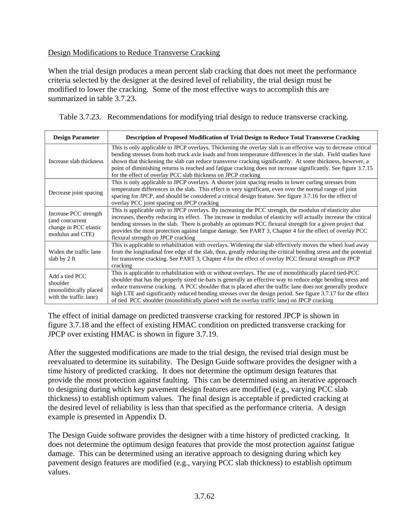
Design Modifications to Reduce Transverse Cracking When the trial design produces a mean percent slab cracking that does not meet the performance criteria selected by the designer at the desired level of reliability, the trial design must be modified to lower the cracking. Some of the most effective ways to accomplish this are summarized in table 3.7.23.
Table 3.7.23. Recommendations for modifying trial design to reduce transverse cracking.
Design Parameter Description of Proposed Modification of Trial Design to Reduce Total Transverse Cracking
Increase slab thickness
This is only applicable to JPCP overlays. Thickening the overlay slab is an effective way to decrease critical bending stresses from both truck axle loads and from temperature differences in the slab. Field studies have shown that thickening the slab can reduce transverse cracking significantly. At some thickness, however, a point of diminishing returns is reached and fatigue cracking does not increase significantly. See figure 3.7.15 for the effect of overlay PCC slab thickness on JPCP cracking
Decrease joint spacing
This is only applicable to JPCP overlays. A shorter joint spacing results in lower curling stresses from temperature differences in the slab. This effect is very significant, even over the normal range of joint spacing for JPCP, and should be considered a critical design feature. See figure 3.7.16 for the effect of overlay PCC joint spacing on JPCP cracking
Increase PCC strength (and concurrent change in PCC elastic modulus and CTE)
This is applicable only to JPCP overlays. By increasing the PCC strength, the modulus of elasticity also increases, thereby reducing its effect. The increase in modulus of elasticity will actually increase the critical bending stresses in the slab. There is probably an optimum PCC flexural strength for a given project that provides the most protection against fatigue damage. See PART 3, Chapter 4 for the effect of overlay PCC flexural strength on JPCP cracking
Widen the traffic lane slab by 2 ft
This is applicable to rehabilitation with overlays. Widening the slab effectively moves the wheel load away from the longitudinal free edge of the slab, thus, greatly reducing the critical bending stress and the potential for transverse cracking. See PART 3, Chapter 4 for the effect of overlay PCC flexural strength on JPCP cracking
Add a tied PCC shoulder (monolithically placed with the traffic lane)
This is applicable to rehabilitation with or without overlays. The use of monolithically placed tied-PCC shoulder that has the properly sized tie-bars is generally an effective way to reduce edge bending stress and reduce transverse cracking. A PCC shoulder that is placed after the traffic lane does not generally produce high LTE and significantly reduced bending stresses over the design period. See figure 3.7.17 for the effect of tied PCC shoulder (monolithically placed with the overlay traffic lane) on JPCP cracking
The effect of initial damage on predicted transverse cracking for restored JPCP is shown in figure 3.7.18 and the effect of existing HMAC condition on predicted transverse cracking for JPCP over existing HMAC is shown in figure 3.7.19. After the suggested modifications are made to the trial design, the revised trial design must be reevaluated to determine its suitability. The Design Guide software provides the designer with a time history of predicted cracking. It does not determine the optimum design features that provide the most protection against faulting. This can be determined using an iterative approach to designing during which key pavement design features are modified (e.g., varying PCC slab thickness) to establish optimum values. The final design is acceptable if predicted cracking at the desired level of reliability is less than that specified as the performance criteria. A design example is presented in Appendix D. The Design Guide software provides the designer with a time history of predicted cracking. It does not determine the optimum design features that provide the most protection against fatigue damage. This can be determined using an iterative approach to designing during which key pavement design features are modified (e.g., varying PCC slab thickness) to establish optimum values.
3.7.62

0
10
20
30
40
50
60
70
80
90
100
0 40 80 120 160 200 240Age, months
Per
cent
sla
bs c
rack
ed9-in 10-in
11-in 12-in
No dowels16-ft joint spacing; AC shoulder No initial cracking (0 percent) 20 million trucks
Figure 3.7.15. Plot showing the effect of slab thickness on overlay transverse cracking of unbonded JPCP overlays.
0
10
20
30
40
50
60
70
80
90
100
0 40 80 120 160 200 240Age, months
Per
cent
sla
bs c
rack
ed
12-ft 16-ft 20-ft
10-in PCC slab; no dowelsAC shoulder; no initial cracking (0 percent) 20 million trucks
Figure 3.7.16. Plot showing the effect of joint spacing on overlay transverse cracking of
unbonded JPCP overlays.
3.7.63

0
10
20
30
40
50
60
70
80
90
100
0 40 80 120 160 200 240Age, months
Perc
ent s
labs
cra
cked
Non Tied ShoulderTied-PCC Monolithically Constructed Shoulder
10-in PCC slab; no dowels16-ft joint spacingNo initial cracking (0 percent) 20 million trucks
Figure 3.7.17. Plot showing the effect of edge support (use of tied PCC shoulders
monolithically placed with the JPCP overlay traffic lane or retrofitted to existing JPCP or non tied PCC shoulder) on transverse cracking of restored JPCP.
0
10
20
30
40
50
60
70
0 40 80 120 160 200 240Age, months
Per
cent
sla
bs c
rack
ed
No Initial Cracking15% Initial Cracking30% Initial Cracking
10-in PCC slab; no dowels16-ft joint spacing; AC shoulder 20 million trucks
Figure 3.7.18. Plot showing the effect of initial damage (transverse cracking) on transverse
cracking of restored JPCP.
3.7.64

0
5
10
15
20
25
0 5 10 15 20Age, yrs
Per
cent
sla
bs c
rack
ed, p
erce
nt
Existing HMAC condition = Very poor (average HMACdynamic modulus = 150,000 psi, Erodibility = 4)
Existing HMAC condition = Excellent (average HMACdynamic modulus = 650,000 psi, Erodibility = 2)
Design life = 20 yrsTwo-way AADTT = 4000No. of trucks = 18.0 millionPCC slab thickness = 8-in28-day PCC MR = 710 psiExisting HMAC thickness = 10-inA-2-7 subbase thickness = 4-inSubgrade type = A-6
Figure 3.7.19. Plot showing the effect of existing HMAC condition on transverse cracking of
JPCP overlays over existing HMAC. 3.7.4.7 JPCP Smoothness Smoothness is the most important pavement characteristic applicable to the highway user. In this Guide, smoothness is defined by IRI. The IRI is dependent on the longitudinal profile of a pavement in the wheelpaths and represents the sum total vertical motion of a “quarter-car” model divided by distance as it passes over a pavement at 50 mph. Pavement smoothness over time affects not only the highway user perception of the highway, but also highway user costs due to increased vehicle operating costs. Loss of smoothness is often a critical situation that triggers rehabilitation of the pavement. Thus, it affects the life cycle costs of any highway pavement over its design life. Smoothness is the result of a combination of the initial as-constructed profile of the pavement and any change in the longitudinal profile over time and traffic. Initial as-constructed profile is influenced by the smoothness specifications. The use of sound construction practices and adopting measures that reduce the amount of built-in curl/warp temperature difference in the PCC would significantly reduce initial smoothness. Change in the longitudinal profile over time occurs for many reasons, but the development of certain pavement distresses will affect smoothness greatly. Key distresses affecting the IRI for JPCP include transverse joint faulting and transverse cracking. Other distresses include settlement or heaves and joint spalling. Thus, building a smooth pavement and then preventing distresses from occurring is a key design objective.
3.7.65

Predicting Smoothness Loss of smoothness is an incremental process that is related to the development of joint faulting and transverse cracking plus other distresses. Smoothness over time is estimated from the initial IRI and the development of joint faulting and total transverse cracking. The following the smoothness prediction is model used for design: IRIM = IRII + C1*CRK + C2*SPALL + C3*TFAULT + C4*SF (3.7.21)
where IRIM = predicted mean smoothness (at 50 percent reliability). IRII = initial smoothness measured as IRI, in/mile.
CRK = percentage of slabs with top-down and bottom up transverse cracking and corner cracking (all severities).
SPALL = percentage of joints with spalling (medium and high severities).
TFAULT = total joint faulting cumulated per mile, in. SF = site factor = AGE*(1+ 0.556 FI)*(1+P0.075). AGE = pavement age, yr. FI = freezing index, oF days. P0.075 = percent subgrade material passing No. 200 sieve. C1 = 0. 8203. C2 = 0.4417. C3 = 1.4929. C4 = 25.24.
Use of this model (including the model for predicting transverse joint spalling) is described in PART 3, Chapter 4. Initial IRI should be selected using the recommendations presented in section 3.7.3 of this chapter. Estimating JPCP Smoothness at a given Design Reliability Level Restored JPCP or JPCP overlays designed with the IRI model presented (equation 3.7.21) will have 50 percent design reliability. That is, they are just as likely to fail before the design life as after the design life. For design purposes a higher reliability than 50 percent may be specified. In these circumstances the predicted transverse cracking must be adjusted upwards to reflect the increase in reliability. The equations used to adjust predicted mean faulting at any given level of reliability is presented below: IRIRMR SZIRIIRI += (3.7.22) where
IRIR = predicted IRI at reliability level R, percent. IRIM = predicted IRI at 50 percent reliability level (equation 3.7.21). ZR = standard normal deviate for the given reliability level R. STDIRI = standard deviation corresponding to the predicted IRI level.
3.7.66

STDIRI is defined as follows: (3.7.23) ( ) 5.02222 321 eFaultSpallCRKIRIiIRI SVarCVarCVarCVarSTD +⋅+⋅+⋅+=
where,
STDIRI = standard deviation of IRI at the predicted level of mean IRI. VarIRIi = variance of initial IRI (obtained from LTPP) = 29.16, (in/mi)2. VarCRK = variance of cracking [equation 3.4.15], (percent slabs)2. VarSpall = variance of spalling (obtained from spalling model) = 46.24, (percent
joints)2. VarFault = variance of faulting [equation 3.4.41], (in/mi)2. Se
2 = variance of overall model error = 745.3 (in/mi)2. Equation 3.7.23 may be modified based on local calibration. Trial Design Performance Evaluation Performance evaluation is the comparison of the predicted IRI over the rehabilitation design life and the user input IRI performance criteria, which is the maximum IRI that should trigger rehabilitation or indicate pavement failure at the desired level of reliability. Excessive levels of predicted IRI typically are due to the occurrence of significant amounts of transverse cracking of JPCP and transverse joint faulting. Inadequate design to control transverse cracking and faulting thus results in user discomfort that triggers rehabilitation. Thus, it is desirable to place limits on predicted IRI to ensure that a JPCP design will provide highway users with reasonable levels of comfort throughout the pavements design period. The critical level of IRI is chosen by the designer and should not be exceeded at the design level of reliability. Modification of JPCP Design to Improve Smoothness When the trial design (for JPCP overlays) produces an IRI that does not meet the performance criteria selected by the designer at the desired reliability level, the trial design should be modified to lower the predicted IRI. The most effective ways to accomplish this include building a smoother pavement initially and minimizing distress. The smoothness prediction model shows that smoothness loss occurs mostly from the development of distresses such as cracking, faulting, and spalling. Minimizing or eliminating such distresses by modifying trial design properties that influence the distresses would result in a smoother pavement. Hence, all of the modifications discussed in previous sections (for cracking and faulting) are applicable to improving smoothness. Another way in which smoothness can be reduced is by constructing a smoother pavement (decrease initial smoothness). This is applicable to JPCP overlays and diamond grinding or restored JPCP. Smoothness specifications that offer significant incentives to build a smooth pavement are standard in many States. These specifications have had a dramatic effect, decreasing the mean IRI over a period of several years of implementation. Thus, it is well
3.7.67

known now that a very smooth pavement can be constructed if proper specifications are used. This will provide the customer with a smoother pavement over a long period of time. For restored JPCP, the most effective way to accomplish a smoother pavement is by diamond grinding to a smoothness approaching that of new construction (except when major settlements or heaves exist that cannot be removed). Figures 3.7.20 shows the effect of initial smoothness and key distress types such as transverse joint faulting and transverse cracking and site variables on unbonded JPCP overlay smoothness. Varying these design features properly reduces mean transverse joint faulting and cracking thereby decreasing smoothness. The effects presented are similar for all of rehabilitation with JPCP. The Design Guide software provides the designer with a time history of predicted smoothness. It does not determine the optimum design features and material properties that provide the most protection against smoothness loss. This can be determined using an iterative approach to designing during which key pavement design features and material properties are modified (e.g., varying PCC slab thickness).
100
120
140
160
180
-50 -40 -30 -20 -10 0 10 20 30 40 50
Percent change in value
Transverse Cracking
Transverse Joint Faulting
Age
Freezing Index
Percent Subgrade passing No. 200 Sieve
Transverse Joint Spalling
Figure 3.7.20. Sensitivity plot showing the effects of changes in key distresses and site variables on JPCP smoothness.
3.7.68

3.7.5 CRCP REHABILITATION DESIGN The key difference between JPCP and CRCP is the use of longitudinal reinforcement steel and no regular transverse joints. Longitudinal reinforcement steel is used not to prevent cracking but rather to hold tightly closed any cracks that may form and prevent their deterioration and the development of punchouts—the distress type that indicates structural deterioration of CRCP. This section describes the procedures used in design of the following rehabilitation strategies:
• Unbonded CRCP over existing rigid or composite pavements. • Bonded PCC over existing CRCP. • CRCP overlay over existing flexible pavement.
The rehabilitation design procedure presented may be performed systematically using the Design Guide software. Figure 3.7.21 presents an overview of the CRCP rehabilitation design procedure. Each trial rehabilitation design must be analyzed in detail to determine if it performs adequately over the expected rehabilitation period at a given reliability level. Performance for CRCP overlays is quantified using punchouts (an indicator of structural adequacy) and smoothness (an indicator of functional adequacy). Detailed descriptions of the procedures for estimating CRCP punchouts and smoothness are presented as part of the design process. 3.7.5.1 Rehabilitation Design Considerations Trial design begins by defining the pavement structure and selecting appropriate design features and material properties to ensure that the development of crack spacing and width are within reasonable acceptable limits (i.e., crack spacing generally ranging from 2 to 6 ft and crack widths at steel depths as tight as needed to prevent the loss of LTE) so they do not adversely affect pavement performance. Guidance for the definition of both the pavement structure and layer material properties is presented in section 3.7.3 of this chapter and PART 3, Chapter 4. Factors that influence crack spacing, crack width, and crack LTE are described in the following sections. Also, some key design features and material properties that must be selected to positively influence crack spacing and width and ultimately pavement performance are presented. Factors that Influence Crack Spacing, Crack Width, and Crack and Joint LTE Transverse Crack Width and Spacing The width of the transverse crack is fundamental to many aspects of CRCP performance, as it plays a dominant role in controlling the degree of load transfer capacity provided at the transverse cracks. It is strongly influence by the design steel content, PCC shrinkage, and PCC CTE. Smaller crack widths increase the capacity of the crack for transferring repeated shear stresses (caused by heavy axle loads) between adjacent slab segments over the long term. Wider cracks exhibit lower and lower LTE over time and traffic, which results in increased load-related critical tensile stresses at the top of the slab, followed by increased fatigue damage and eventually the development of punchouts. Field studies have shown that longer crack spacing increases the potential for wider opening of transverse cracks. Mean crack spacing must therefore be limited (< 6 ft).
3.7.69
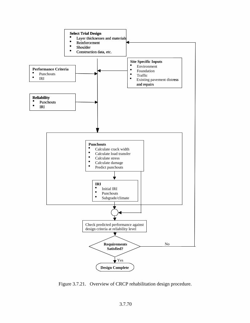
Select Trial Design• Layer thicknesses and materials• Reinforcement• Shoulder• Construction data, etc.
Site Specific Inputs• Environment• Foundation• Traffic
Performance Criteria• Punchouts• IRI
IRI• Initial IRI• Punchouts• Subgrade/climate
Punchouts• Calculate crack width• Calculate load transfer• Calculate stress• Calculate damage• Predict punchouts
Check predicted performance against design criteria at reliability level
Yes
NoRequirements Satisfied?
Design Complete
Reliability• Punchouts• IRI
• Existing pavement distress and repairs
Figure 3.7.21. Overview of CRCP rehabilitation design procedure.
3.7.70

The physical mechanism through which cracks develop and hence can be controlled for unbonded CRCP overlays and CRCP overlays of existing flexible pavement is affected by:
• Temperature/moisture slab contractions. • Frictional resistance from the underlying pavement. • Resistance from longitudinal reinforcement.
As temperature drops and moisture content decreases, the slab tends to contract. The contraction is resisted by the underlying layer through friction and shear. Longitudinal reinforcement also resists this shrinkage. The restraint on the overlay PCC slab contraction results in tensile stresses that reach a maximum at midpoint between two cracks. If these tensile stresses exceed the tensile strength of the PCC, another crack develops and all the tensile stress is transferred to the longitudinal steel reinforcement. Longitudinal reinforcement, therefore, must be selected to carry these stresses without excessive elongation that would result in excessive crack width. Temperature and moisture within the PCC slab can also be controlled by applying sound construction practices (e.g., adequate curing). Construction in hot summer days results in high zero-stress temperatures (the temperature at which the PCC begins to develop tensile stress is the zero-stress temperature) and wider crack openings. Also, both crack width and spacing can be controlled through the selection of base types that affects the frictional and shear restraining forces that are imposed on the CRC slab. For bonded PCC over existing CRCP, both crack spacing and width are controlled by the cracking patterns of the existing CRC slab. Therefore, it may not be a feasible rehabilitation strategy if the existing shows excessive crack widths that may lead to premature failure. Transverse Crack LTE The load transfer of transverse cracks is a critical factor in controlling the development of punchout-related longitudinal cracking. Maintaining load transfer of 95 percent or greater (through aggregate interlock over the CRC overlay design life) will limit the development of punchout distress. This is accomplished by limiting crack width over the entire year, especially the cold months. Crack LTE can be controlled for unbonded CRCP overlays and CRCP overlays over existing flexible pavement as described for new CRCP in PART 3, Chapter 4. For bonded PCC over existing CRCP the cracking patterns assume the same form as those in the existing CRCP. Lane to Shoulder Longitudinal Joint Load Transfer The load transfer of the lane to shoulder joint affects the magnitude of the tensile bending stress at the top of the slab (between the wheel loads in a transverse direction)—the critical pavement response parameter that controls the development of longitudinal cracking between adjacent transverse cracks and, consequently, the development of punchout. The use of design features that could provide and maintain adequate edge support throughout the pavement rehabilitation design life is therefore key to adequate performance. Field studies have shown that the use of tied PCC shoulders and non-erodible underlying materials significantly improves edge support
3.7.71

and pavement performance. If tied PCC shoulders are utilized, the erodibility of the base may be increased one level due to the reduction in edge deflections. Design Features Overlay PCC Slab Thickness This is an important design feature from the standpoint of slab stiffness that has a very significant influence on performance. Note that for bonded PCC over existing CRCP the equivalent stiffness of the overlay and existing PCC layer is used in analysis. In general, as the slab thickness of a CRC overlay increases, the capacity to resist critical bending stress increases, as does the slab’s capability to transfer load across the transverse cracks. Consequently, the rate of development of punchouts decreases and smoothness loss is also reduced (29, 30). Slab thickness must be selected within the context of other design features, including percent steel reinforcement and base type and stiffness. This is because certain combinations of these pavement design features may adversely influence crack spacing and width and hence pavement performance. For CRCP overlays, the goal is normally to select the minimum thickness with adequate reinforcement that provides very tight cracks over the design period at the desired level of reliability. The practical minimum thickness is approximately 7-in for construction purposes. Percentage (By Area) of Longitudinal Reinforcement and Depth of Reinforcement Longitudinal steel reinforcement is an important design parameter because it is used to control the opening of the transverse cracks for unbonded CRCP overlays and CRCP overlays over existing flexible pavement. Also, the depth at which longitudinal reinforcement is placed below the surface also greatly affects crack width. It is recommended that longitudinal steel reinforcement be placed above mid-depth in the slab. Studies have shown that placing the reinforcement above mid depth results in much tighter cracks and shorter crack spacing (29, 30, 31). Generally, a minimum steel depth of 3.5 in and an absolute maximum of mid-depth are recommended (15). For bonded PCC over existing CRCP, the amount of reinforcement entered into the models is the same as that of the existing CRCP because cracks are already formed and no reinforcement is placed in the overlay PCC. Depth of the steel reinforcement is equal to the depth to the reinforcement in the existing CRCP (ignore the overlay PCC thickness because cracks are already formed through the slabs). Slab Width Slab width has typically been synonymous with lane width (usually 12 ft). Widened lanes typically are 14 ft. Field and analytical studies have shown that the wider slab keeps truck axles away from the free edge, greatly reducing tensile bending stresses (in the transverse direction) at the top slab surface and deflections at the lane-shoulder joint. This has a significant effect on reducing the occurrence of edge punchouts (31). This design procedure does not directly address CRCP with widened slabs. However, as with JPCP, the critical wheel location would shift to the
3.7.72

inner longitudinal joint and thus modeled as a tied PCC shoulder with increased mean lateral wheel offset (30 in maximum). Therefore, a CRCP with a widened lane could be designed by specifying a tied PCC shoulder and an increased lateral offset. Transverse Reinforcement Steel Transverse reinforcement steel is not directly considered in this Design Guide. It is often specified to assist construction of the CRCP (to hold the longitudinal steel in place) and to hold any longitudinal cracks tight. Subsurface Drainage The design of subsurface drainage facilities for new and rehabilitated CRCP is addressed in PART 3, Chapter 1. If edge drains are specified then the “minor” infiltration can be specified. Shoulder Type The use of tied PCC shoulders generally decreases the amount of slab edge deflections experienced and keeps cracks tighter. Various shoulder types also affect the level of infiltration of moisture into the pavement system and hence the erosion potential of the underlying layers. A detailed description of shoulder design is presented in PART 3, Chapter 2. The effect of shoulder design on punchouts is presented in PART 3, Chapter 4. Layer Material Properties CRC/PCC Materials Properties The PCC material properties that must be considered in design and construction of CRCP include compressive strength, flexural strength, tensile strength, coefficient of thermal expansion, thermal diffusivity, heat of hydration, modulus of elasticity, ultimate drying shrinkage, and aggregate type. Guidance for obtaining these properties has been provided in section 3.7.3 of this chapter. The effect of PCC material properties on new CRCP performance applicable to overlays is described in PART 3, Chapter 4. The designer is cautioned that when the PCC mix is altered many other mix properties will change and all these should be appropriately reflected by the PCC inputs entered into the design guide software (e.g., change in PCC compressive strength results in changes in flexural strength, elastic modulus, CTE and so on). Base Type The base type and material characteristics are critical features that affect the crack spacing, crack width, PCC slab support, and loss of support (erosion). Field studies have shown that the use of different base types can produce significant variation is cracking patterns. This is because of the difference in frictional stresses produced as a result of the friction experience between the different material types and PCC. Also, the degree to which the frictional stresses will be developed is dependent on climate-related variables such as ambient temperature variability and
3.7.73

the PCC coefficient of thermal expansion. These factors can strongly influence the performance of CRCP overlays and are addressed in PART 3, Chapter 4. Use the recommended values in table 3.4.2. 3.7.5.2 Performance Criteria Design performance criteria are required to ensure that the CRCP will perform adequately over the rehabilitation design life. The primary structural distress type associated with CRCP is punchouts. It is an indicator of structural failure. The functionality of the pavement is evaluated using smoothness (measured as IRI). The selection of appropriate performance criteria is described in section 3.7.3 of this chapter. 3.7.5.3 Rehabilitation Trial Design Trial design basically consists of estimating crack widths, CRCP punchouts, and smoothness (IRI) over the rehabilitation design life. A punchout is defined as the segment of PCC between two closely spaced cracks (typically 2 ft) where a longitudinal crack occurs (typically 4 to 5 ft from the slab edge). The longitudinal crack typically begins as micro-cracks at the top surface of the CRC overlay slab, coalesces as a longitudinal hairline crack with the application of repeated traffic loads, and finally propagates downward through the CRC slab to form a punchout (29, 30, 32). CRCP punchouts are, therefore, the result of a combination of the following factors:
• Construction conditions (including concrete zero-stress temperature (affects crack width) and permanent curling/warping).
• Irregular transverse crack spacing with large numbers of narrow (2 ft or less) cracked PCC segments.
• Excessive transverse crack width (> 0.020 in) in cold periods. • Application of repeated heavy axle loads to the CRCP. • Free moisture beneath the CRC slab (within the underlying layers). • Erosion of the layers underlying the CRC slab (base/subbase, or subgrade) resulting in
high slab edge deflections when loaded. • Loss of load transfer (LTE < 95 percent) across the adjacent transverse cracks (influenced
greatly by crack width). • Inadequate CRC slab thickness to control fatigue damage.
Punchout Prediction Punchout prediction begins with computing the pavements critical structural responses—tensile bending stress in the top surface of the CRC in the transverse direction. This is followed by computing fatigue damage (computed using the critical structural responses and applied traffic). Fatigue damage is then used to compute punchouts. A detailed description of the punchout prediction procedure is presented in PART 3, Chapter 4 and summarized in the following sections.
3.7.74

Structural Modeling and Computing Critical Structural Responses For this design procedure the CRCP critical pavement responses were computed using rapid solution NN models that are based on FE structural analysis. The NN models were developed specifically for the rehabilitation strategies covered by this guide and are based on the following assumptions:
• An unbonded interface is assumed between the PCC slab and the base (for unbonded and bonded overlays) and hence, base unit weight is set equal to 0. For CRCP overlays over existing flexible pavements bonding condition is a user input. Good bonding is important and beneficial.
• The coefficient of thermal expansion of the base layer is equal to the PCC coefficient of thermal expansion.
Results from the NN models are rapid and accurate. A detailed description of the software and neural networks developed for computing structural responses are presented in PART 3, Chapter 4. Note that because damage is accumulated incrementally and pavement design features, material properties, and climate vary for the different time increments, the critical pavement response parameter—maximum transverse tensile stress at the top surface (in the transverse direction) between two closely spaced transverse cracks—must be computed for each time increment throughout the rehabilitation design life.
Estimating Fatigue Damage and Punchouts Next after computing the pavement critical structural responses is to estimate fatigue damage and punchouts for unbonded CRCP overlays, bonded PCC overlays of CRCP, and CRCP overlays of flexible pavements. Presented in this section is the step-by-step procedure for predicting CRCP punchouts. The steps involved include the following: Step 1. Tabulate Input Data Summarize all inputs needed for predicting CRCP punchouts. See PART 3, Chapter 4 for detailed input guidance. Step 2. Process Traffic Data The processed traffic data needs to be further processed to determine equivalent number of single, tandem, and tridem axles produced by each passing of tandem, tridem, and quad axles. See PART 3, Chapter 4 for detailed input guidance. Step 3. Process Pavement Temperature Profile Data The hourly pavement temperature profiles generated using EICM (nonlinear distribution) need to be converted to distribution of equivalent linear temperature differences by calendar month. Temperatures also used to compute the dynamic modulus of asphalt concrete separation layers and asphalt stabilized base courses. See PART 3, Chapter 4 for detailed input guidance.
3.7.75

Step 4. Calculation of Crack Spacing Accurate prediction of the transverse cracking pattern is extremely important for a successful CRCP overlay design. Transverse cracking is characterized by crack spacing and crack opening. Generally, larger crack spacing results in wider crack opening. Several parameters affect crack spacing and crack opening including PCC shrinkage, PCC thermal contraction, PCC tensile strength, PCC zero-stress temperature at construction, amount and depth of steel reinforcement, and base layer friction. See PART 3, Chapter 4 for detailed input guidance. Steps 5 through 9 are performed for each month in the design period. See PART 3, Chapter 4 for detailed input guidance. Step 5. Calculation of Crack Width and Crack LTE Crack width should be limited to 0.02 in at steel level and LTE to greater than 95 percent throughout the design period. Step 6. Calculation of Loss of Support along Longitudinal Edge of slab Step 7. Calculation of Critical Stress Calculate critical top of slab transverse stress corresponding to each load configuration (axle type), load level, lateral load position, and temperature difference for one month. Step 8. Calculate Deterioration of Crack Stiffness Step 9. Process Monthly Relative Humidity Data The effects of seasonal changes in moisture conditions on differential shrinkage is considered in terms of monthly deviations in slab warping, expressed in terms of effective temperature difference. Step 10. Calculate Fatigue Damage Calculate damage for each damage increment and sum to determine total damage. See PART 3, Chapter 4 for detailed input guidance. Step 11. Determine the Amount of Punchouts A calibrated model for punchout prediction as a function of accumulated fatigue damage due to slab bending in the transverse direction is used in this design procedure. The model has the following functional form:
5
4
3
1 CPOFDC
CPO
+= (3.7.24)
where, PO = total predicted number of punchouts per mile.
3.7.76

FD = accumulated fatigue damage (due to slab bending in the transverse direction) at the end of the design life. C3, C4, C5 = calibration constants. Equation 3.7.24 was calibrated with field data from LTPP and other sources to assure that it would produce valid results under a variety of climatic and field conditions. The model coefficients are summarized in table 3.7.24 for the different rehabilitation strategies. The CRCP transverse punchout model coefficients given in table 3.7.24 are a result of calibration using data obtained from 42 in-service pavements from the LTPP GPS-9 and SPS-7 experiments and NCHRP 10-41 study located in 10 States. For CRCP overlays over existing flexible pavement models coefficients developed for new pavement were adopted.
Table 3.7.24. Coefficients for models used in predicting punchouts for selected rehabilitation
strategies.
Rehabilitation Strategy Model
coefficient Unbonded CRCP Overlay
Bonded PCC Overlay over
Existing CRCP
CRCP Overlay over Existing Flexible Pavement
C3 105.26 105.26 105.26 C4 4.0 4.0 4.0 C5 -0. 3815 -0. 3815 -0. 3815 R2 0.82 — — N 29 — —
Alternately, local and regional field data can be used to obtain calibrated models. An advantage of performing local/regional calibration is smaller inference space resulting in a more accurate model. The disadvantage of performing local/regional calibration is that there may not be adequate number of sections representing the wide variety of designs that a particular agency may use. Estimating CRCP Punchouts at a given Design Reliability Level CRCP overlays designed with the punchout model presented (equation 3.7.24) and mean inputs will have 50 percent design reliability. A higher reliability than 50 percent is nearly always desired. The predicted punchouts are adjusted upwards to reflect the increase in reliability. The equations used to adjust predicted mean punchouts PORMR SZPOPO += (3.7.25) where
POR = predicted punchouts/mile at reliability level R, percent. POM = predicted punchouts/mile at 50 percent reliability level. ZR = standard normal deviate for the given reliability level R (one-tailed). SPO = standard deviation corresponding to the predicted punchout level,
punchouts/mile.
3.7.77

SPO is defined as follows:
372.025.4 += MPO POS (3.7.26) Equation 3.7.26 may be modified based on local calibration. Trial Rehabilitation Design Performance Evaluation Performance evaluation is the comparison of the predicted punchout over the rehabilitation design life and the user input punchout performance criteria, which is the maximum punchouts/mile that would trigger rehabilitation or indicate pavement failure at the desired level of reliability. Modification of Rehabilitation Design Features to Reduce Punchouts The CRCP rehabilitation design procedure requires the selection of a trial design. This design is then analyzed and punchouts predicted over the design life. If predicted punchouts exceed the design criteria, the trial design must be modified. Crack width, slab thickness, and poor support conditions are the primary factors affecting CRCP performance and punchout development and hence modifying the factors that influence them is the most effective manner of reducing punchouts. Crack spacing cannot be modified for bonded PCC over existing CRCP.
• Increase overlay slab thickness. An increase in CRCP slab thickness will reduce punchouts based on (1) a decrease in tensile stress at the top of the slab, (2) an increase in crack shear capability and a greater tolerance to maintain a high load transfer capability at the same crack width that also allows for reduced tensile stress at top of the slab. Figures 3.7.22 and 3.7.23 show the effect of overlay PCC thickness on punchouts for unbonded and bonded CRCP overlays respectively. The same effect is expected for other overlay types.
• Increase percent longitudinal reinforcement in overlay. Even though an increase in steel content will reduce crack spacing, it has been shown to greatly reduce punchouts overall due to narrower cracks widths. Figure 3.7.24 shows the effect of the amount of longitudinal reinforcement on punchouts for unbonded overlays. The same effect is expected for other overlay types.
• Reduce the PCC Zero-Stress Temperature through improved curing procedure (water curing). The higher the PCC zero-stress temperature the wider the crack openings at lower temperature.
• Reduce the depth of reinforcement in overlay. This is applicable only to unbonded CRCP overlay and CRCP over existing flexible pavement. Placement of steel closer to the pavement surface reduces punchouts through keeping cracks tighter. (However, do not place closer than 3.5 in from the surface to avoid construction problems and limit infiltration of chlorides.)
3.7.78

0
5
10
15
20
25
30
35
40
0 5 10 15 20 25 30Age, years
No.
of p
unch
outs
per
mile
Overlay thickness = 7-inOverlay thickness = 9-inOverlay thickness = 11-in
20 million trucks0.7 percent steel; 28-day MR = 690 psi10-in existing PCC slab (base in moderate condition)1-in HMAC sep. layer; 6-in granular base; A-7-6 subgrade material
Figure 3.7.22. Plot showing the effect of overlay slab thickness on punchouts for unbonded
CRCP overlays.
0
5
10
15
20
25
0 5 10 15 20 25 30Age, years
No.
of p
unch
outs
per
mile
Bonded overlay thickness = 3-inBonded overlay thickness = 5-in
20 million trucks0.6 percent steel; 28-day MR = 690 psi8-in existing PCC slab (base in good condition)6-in granular base; A-7-6 subgrade material
Figure 3.7.23. Plot showing the effect of overlay slab thickness on punchouts for bonded PCC
over CRCP overlays.
3.7.79

0
2
4
6
8
10
12
14
16
0 5 10 15 20 25 30Age, years
No.
of p
unch
outs
per
mile
Percent steel = 0.6Percent steel = 0.7Percent steel = 0.8
20 million trucks28-day MR = 690 psi9-in overlay slab; 10-in existing PCC slab (base in moderate condition)1-in HMAC sep. layer; 6-in granular base; A-7-6 subgrade material
Figure 3.7.24. Plot showing the effect of the amount of longitudinal reinforcement on
punchouts for unbonded CRCP overlays.
• Increase PCC tensile strength. Increasing of CRCP tensile strength decreases the fatigue damage and hence punchouts. It must be noted however that there is a corresponding increase in PCC modulus which increases the magnitude of stresses generated within the PCC reducing the benefit of increase tensile strength. See PART 3, Chapter 4 for the effect of increased overlay PCC tensile strength on punchouts for unbonded overlays. The same effect is expected for other overlay types.
• Reduce coefficient of thermal expansion of overlay PCC. Use of a lower thermal coefficient of expansion concrete will reduce crack width opening for the same crack spacing. See PART 3, Chapter 4 for the effect of CTE on punchouts for unbonded overlays. The same effect is expected for other overlay types.
• Increase hot mix AC separator layer thickness. The thicker the separator layer the less sensitive the overlay is to the deterioration in the existing pavement. This is especially true as the overlay ages as shown in figure 3.7.25. For badly deteriorated existing pavements thick hot mix AC separator layers are recommend for CRCP overlays.
• Increase CRCP/base friction. Use an asphalt or cement treated base. The effect of the existing pavement condition on unbonded CRCP overlays is shown in figure 3.7.26.
3.7.80

0
1
2
3
4
5
6
0 5 10 15 20 25 30Age, years
No.
of p
unch
outs
per
mile
HMAC Sep. Layer thickness = 1-inHMAC Sep. Layer thickness = 4-in
20 million trucks0.7 percent steel; 28-day MR = 690 psi9-in overlay slab10-in existing PCC slab (moderate condition; CBD = 0.22)6-in granular base; A-7-6 subgrade material
Figure 3.7.25. Plot showing the effect of hot mix AC separator layer thickness on punchouts for
unbonded CRCP overlays.
0
5
10
15
20
25
0 5 10 15 20 25 30Age, years
No.
of p
unch
outs
per
mile
Existing pavement condition = Good (1.0)Existing pavement condition = Moderate (0.42)Existing pavement condition = Severe (0.042)
20 million trucks0.7 percent steel; 28-day MR = 690 psi9-in overlay slab; 10-in existing PCC slab1-in HMAC sep. layer; 6-in granular base; A-7-6 subgrade material
Figure 3.7.26. Plot showing the effect of existing pavement condition on unbonded CRCP
overlays punchouts.
3.7.81

CRCP Smoothness The smoothness of CRCP is the most critical consideration for the traveling public. A typical highway pavement loses smoothness over time until it triggers pavement rehabilitation or restoration. The critical level of smoothness is a user input based on local standards and recommendations of user’s assessment of ride quality. Predicting CRCP Smoothness (IRI) Smoothness is the result of a combination of the initial as-rehabilitated smoothness and changes in the longitudinal profile over time and traffic. The IRI prediction model for CRCP is given as follows: IRIM = IRII + C1*PUNCH + C2*SF (3.7.27) where, IRII = initial IRI, in/mile. PUNCH = number of medium- and high-severity punchouts/mile. SF = site factor = AGE*(1+0.556 FI)*(1+P0.075)/1000000. AGE = pavement age, yr. FI = freezing index, oF days. P0.075 = percent subgrade material passing No. 200 sieve. C1 = 3.15 C2 = 28.35 The input distress punchouts will be obtained from the punchout model presented in the preceding section. Other inputs such as climate and subgrade properties are directly input by the user as described in section 3.7.3 or computed by EICM. Initial smoothness—a key input—is obtained as described in section 3.7.3 of this chapter. Equation 3.7.27 was calibrated and validated with LTPP data to ensure that it would produce valid results under a variety of climatic and field conditions. Estimating CRCP Smoothness at a given Design Reliability Level CRCP overlays designed with the smoothness model presented (equation 3.7.27) will have 50 percent design reliability. For design purposes, a higher reliability than 50 percent is desired. The predicted smoothness must be adjusted upwards to reflect the increase in reliability. The equations used to adjust predicted mean smoothness at any given level of reliability is presented as follows:
IRIRMR STDZIRIIRI += (3.7.28) where,
IRIR = predicted IRI at reliability level R, percent, in/mi. IRIM = predicted IRI at 50 percent reliability level, in/mi.
ZR = standard normal deviate for the given reliability level R (one tail distribution).
3.7.82
STDIRI = standard deviation corresponding to the predicted IRI level, in/mi.
( ) 5.0221 ePOIRIiIRI SVarCVarSTD +⋅+= (3.7.29)
VarIRIi = variance of initial IRI (obtained from LTPP) = 29.16 (in/mi)2. VarPO = variance of punchout [equation 3.4.70]) (No./mi)2. Se
2 = variance of overall model error = 213.2 (in/mi)2.
Equation 3.7.29 may be modified based on local calibration. Trial Rehabilitation Design Performance Evaluation Performance evaluation is the comparison of the predicted IRI over the rehabilitation design life and the user input IRI performance criteria, which is the maximum IRI that should trigger rehabilitation or indicate pavement failure at the desired level of reliability. Excessive levels of predicted IRI typically are due to the occurrence of significant amounts of punchouts. Inadequate design results in user discomfort that triggers rehabilitation. Thus, it is desirable to place limits on predicted IRI to ensure that a JPCP design will provide highway users with reasonable levels of comfort throughout the pavements design period. The critical level of IRI is chosen by the designer and should not be exceeded at the design level of reliability. Modification of CRCP Design to Improve Smoothness When the trial design produces an IRI that does not meet the performance criteria selected by the designer at the design reliability level, the trial design can be modified to lower the IRI. One effective way to accomplish this for CRCP overlays are to build a smooth CRC overlay. Several States have adopted specifications that have dramatically decreased the mean initial IRI for newly construction pavements over a period of several years of implementation. Thus, it is well known that a very smooth pavement can be constructed. This will provide the customer with a smoother pavement over a longer period of time. Another important aspect is to minimize or eliminate distresses such as punchouts that cause the loss of smoothness. This is done by selecting design features and materials properties that reduce the occurrence of punchouts. The effect of punchouts, site conditions, and initial smoothness is presented in figure 3.7.27.
3.7.83

100
120
140
160
180
200
-50 -40 -30 -20 -10 0 10 20 30 40 50Percent change in value
IRI,
in/m
ile
Age
Punchouts
Freezing Index
Percent Subgrade passing No. 200 Sieve
Figure 3.7.27. Effect of distress and site variables on CRCP smoothness.
3.7.6 ADDITIONAL CONSIDERATIONS FOR REHABILITATION WITH PCC DESIGN (JPCP AND CRCP) There are several important considerations that must be addressed as part of rehabilitation design to ensure adequate performance of the rehabilitation design throughout its design life. These issues include:
• Shoulder reconstruction. • Lane widening. • Lane addition. • Subdrainage improvement. • CPR/preoverlay repairs. • Separator layer design (for unbonded JPCP/CRCP over existing rigid pavements). • Joint design (for JPCP overlays). • Reflection crack control (for bonded PCC over existing JCPC/CRCP). • Bonding (for bonded PCC overlays over existing JPCP/CRCP). • Rubblizing existing rigid pavements.
These design considerations are described in the following sections. 3.7.6.1 Shoulder Reconstruction Utilize the information on the design of shoulders presented in PART 2, Chapter 2 of this guide.
3.7.84

3.7.6.2 Lane Widening Utilize the information presented on lane widening in PART 3, Chapter 4 of this guide. 3.7.6.3 Subdrainage Improvement Utilize the information on the design of subsurface drainage systems described in PART 3, Chapter 1 of this guide. 3.7.6.4 CPR/Pre-Overlay Repairs CPR and pre-overlay repairs include concrete pavement repair treatments that improve on the existing pavement structural capacity or functionality. Pre-overlay repairs are required to repair localized areas within a given project with major deterioration to meet the following objectives:
• Provide reasonably uniform support for the overlay (most important). • Eliminate excessive localized deflections, especially at joints and cracks without effective
load transfer. • Eliminate the further progression of durability-related distresses in the existing pavement
that will cause premature failure of the JPCP/CRCP overlays. The type and extent of pre-overlay repair is dependent upon the following:
• Condition of existing pavement. • Type and thickness of separator layer (for unbonded overlays). • Projected future traffic. • Type of unbonded overlay JPCP or CRCP).
Existing pavement condition may be determined using the procedures outlined in PART 2, Chapter 5. Existing pavements in fairly good condition (as is mostly the case with bonded overlays and JPCP suitable for restoration) will require only moderate repairs to restore uniformity of support and minimize the potential for further deterioration. Pavements experiencing extensive amounts of medium to high-severity distress will require additional repairs or the use of thick AC separator layers to minimize the possibility of existing distress reflecting into the overlay and resulting in premature failure. When repair is necessary, it is important to clearly identify the specific distresses and locations that need repairs, the exact boundaries for repair, and the design of the repair that will be most suitable. Repair alternatives that have been used include AC partial-depth patching, full-depth PCC joint and crack repair, full-depth repair of blowups, and slab replacement. Fracturing of the existing pavement is a potential preoverlay treatment if the existing pavement is very badly deteriorated and highly variable. A detailed description of the CPR/preoverlay repairs is presented in several publications referenced in this chapter. A brief summary is presented in the following sections.
3.7.85
3.7.86
Preoverlay Repairs for Unbonded Concrete Overlays over Existing PCC Pavements Typically, not much pre-overlay repair is required for unbonded JPCP overlays. However, some repairs may be necessary for unbonded CRCP overlays to improve poor joint and crack LTE. The distresses that require particular attention for both unbonded JPCP and CRCP overlays fall into the following three categories:
• Joint-related distresses in jointed concrete pavement. • Non-joint-related distresses (working cracks) that significantly reduce the structural
capacity of the existing pavement including loss of support (high corner deflections). • PCC durability-related distresses with the propensity to get worse.
Repairs commonly applied to existing jointed pavements (JPCP and JRCP) and CRCP are summarized in table 3.7.25. Preoverlay Repairs for Bonded Concrete Overlays over Existing PCC Pavements For bonded overlays, a variety of preoverlay repairs are needed to bring an existing (deteriorated) concrete pavement to an adequate condition before the overlay can be constructed. Bonded overlay performance is extremely sensitive to the quality of the existing concrete and the extent and severity of cracking in the existing pavement. Nearly all cracks will eventually reflect through the overlay. Significant distress types such as pumping, faulting, cracking, and punchouts must be repaired before a bonded overlay is placed. Table 3.7.26 lists the recommended preoverlay repairs for selected commonly occurring distresses such as pumping, corner breaks, punchouts (CRCP only), joint spalling, D-cracking, and transverse cracking (13). Preoverlay Repairs for JPCP/CRCP Overlays over Existing Flexible Pavements For existing flexible pavements, preoverlay repairs involve the following activities:
• Milling of the existing hot mix AC surface layer to level the surface is very important (the PCC overlay should not be counted on to level up the existing pavement).
• Placing a leveling AC course on the hot mix AC. • Combination of milling and level up AC layer when major profile problems exist.
Milling Existing Hot Mix AC Minor ruts and other surface irregularities are filled by the concrete overlay. No milling or other procedures are necessary. If there is unevenness in the longitudinal or transverse profile, milling or a leveling layer is essential to achieving a smooth surface. Direct placement is recommended where rutting does not exceed 1 in maximum depth. Because no surface preparation is necessary, direct placement is very cost-effective.

Existing Pavement Type Distress Recommended Repair
Spalling
A key distress type that exists at badly deteriorated joints and cracks and may require repair is high severity spalls. Any loose material resulting from spalling should be removed. If a thick separator layer (> 1 in hot mix AC) is to be used no other repair is necessary; however, the loose materials should be replaced with appropriate material if a thinner separator layer will be used
Faulting
Joint of crack faulting is usually not a problem when a hot mix AC separation layer of 1-in or more is utilized. For CRCP unbonded overlay, if the measured joint load transfer in the existing JPCP or JRCP faulted joints is less than 50 percent, the hot mix AC separator layer thickness should be greater than 1.5 in to minimize reflection up into the CRCP. Also, CRCP overlay reinforcement can also be increased to minimize any deterioration of a crack over the joint. Another option is to fracture the existing pavement to obtain a more uniform support
PCC durability
The effect of durability related distress (D-cracking, ASR, etc.) in the existing concrete pavement on the overlay can be minimized by the placement of a thicker separator layer (> 1 in hot mix AC) between the existing concrete and the overlay. The effectiveness of the overlay is enhanced if loose pieces of concrete from the distressed concrete layer are removed prior to the placement of the overlay. Since water is a primary ingredient for durability distress, any measures taken to provide positive drainage will reduce the propensity of the existing pavement to continue to deteriorate (see Part 3, Chapter 1 of this guide). Fracturing of the D-cracked pavements to obtain a quality aggregate base is another viable alternative
JPCP or JRCP
Loss of support
Loss of support under the existing pavement can result from rocking slabs, curling and warping of the pavement slabs, and loose shattered slabs. Following are the recommended repair methods for such existing pavements: • Rocking or unstable slabs with large deflections or pumping problems should be replaced full-depth. • Badly shattered slabs with working cracks should be replaced full-depth. • Settlements should be leveled-up with asphalt concrete (this is important to reduce large thickness variations in the
PCC overlay). Fracturing of the pavement into a good quality aggregate base is also a viable option for repairing existing pavements with several badly shattered slabs
Punchouts
Preoverlay repair of CRCP should include full-depth reinforced repair of all punchouts exhibiting high deflections. Because punchouts are more likely to occur as a result of a lack of support provided by the subbase or subgrade, repair of the foundation is very important. Excavation and recompaction of the subbase or subgrade (1.6 to 3.3 ft) beyond the distress boundaries is recommended CRCP
Deteriorated transverse cracks
Deteriorated or working transverse cracks with ruptured steel should also be repaired with full-depth reinforced patches. Similarly, construction joints with high-severity spalls should be repaired with full-depth patches
Table 3.7.25. Summary of repairs commonly applied to existing jointed pavements (JPCP and JRCP) and CRCP (14, 15).
3.7.87

Table 3.7.26. Description of preoverlay repairs required prior to the placement of bonded overlays (13).
Distress Type Critical Severity Preoverlay Repair Procedure
Corner breaks Low • Slab stabilization • Load transfer restoration with full-depth repair
Punchouts (CRCP only) Low • Full-depth reinforced repair
Joint spalling Medium • Partial-depth repair • Full-depth repair (where deterioration extends
beyond mid depth)
D-cracking Medium • Partial-depth repair • Full-depth repair (where deterioration extends
beyond mid depth)
Transverse cracking Medium • Load transfer restoration with full-depth repair • Saw joint above repair joint
Longitudinal cracking Medium • Cross-stitch crack • Place reinforcement bars across crack
For existing flexible pavements with significant amounts of rutting (> 1 in) and other kinds of longitudinal or transverse surface distortions, preoverlay repairs consist of removing these distortions using a profile milling or planing machine. Milling off 1 to 3 in of the existing surface usually produces a uniform profile. Milling also establishes the finished grade line and adjusts the cross slope as needed before the placement of the overlay. The PCC overlay is thus constructed on the milled hot mix AC surface, which acts as trimmed asphalt stabilized base course. Another advantage of milling and trimming the existing hot mix AC surface is that the PCC overlay thickness does not vary significantly along the highway. An evaluation of the existing hot mix AC for stripping potential is recommended. This layer will now be subjected to far more moisture than as a surface layer. Placement of a Leveling Course A uniform paving surface can also be achieved by placing a hot mix AC leveling course on top of the existing pavement surface. The typically average leveling course thickness is 1 in and this is adequate for correcting most surface deviations in the existing flexible pavement. The hot mix AC used in the leveling course generally meets standard design specifications and employs conventionally graded aggregates. Placement of a leveling course is usually more expensive than milling. Because of its expense, this option should not be considered where surface distortions such as rutting are less than 1 in. 3.7.6.5 Separator Layer Design for JPC and CRC Unbonded Overlays The separator layer lies between the existing pavement surface and the JPCP/CRCP overlay for unbonded overlays. The main purposes of the separator layer are to isolate the overlay PCC from the underlying deteriorated pavement and prevent reflection cracking as well as to contribute to the uniform support provided to the overlay. The separation layer can also serve as a leveling course for existing pavements with significant amounts of surface irregularities and distortions.
3.7.88
Even though the primary purpose of a separator layer is to create a barrier between the existing concrete slab and overlay preventing the reflection of distress into the overlay, some of the materials used as separator layers have additional qualities such as being permeable enough to serve as a drainage layer (33, 34). The best material used as separator layers by far has been a relatively thick (> 1 in) hot mix AC. A hot mix AC separator layer provides a uniform support for the overlay that prevents the development reflection of cracks in the overlay. It also minimizes potential for faulting in non-doweled JPCP overlays (27). Generally the best performing unbonded concrete overlays are those constructed with uniform support provided by both the existing slab and separator layer (14, 15). Selection of the proper separation layer requires the consideration of the following factors:
• Type of overlay: JPCP overlays are not very sensitive to deterioration in the existing pavement as long as at least a 1 in AC separation layer is placed. Placement of the JPCP or CRCP directly on an existing concrete pavement may lead to significant reflection cracking from joints and cracks and is not recommended. CRCP is more sensitive to the underlying pavement condition (particularly the LTE of existing joints and cracks) and may sometimes require a thicker AC separation layer or more repair.
• Condition and profile of the existing pavement: There is a wide range of conditions that an old rigid pavement could exhibit. Defining these conditions in detail is practically impossible. The key factor is whether there is vertical movement at existing joints and cracks (poor load transfer). If this situation exists throughout the existing concrete pavement, then the potential for reflection cracking is greater and a thicker separation layer or repairs may be warranted. If the profile exhibits lots of settlements and/or heaves then a thicker separation layer is required to serve also as a level up so that the overlay can be placed with an even thickness and adequate smoothness.
• Repairs to be performed on the existing pavement: When the existing pavement is badly deteriorated it is not cost effective to perform lots of repairs. In this case, a lower condition factor should be assigned (which will result in a thicker overlay) and perhaps a thicker separation layer may be needed. However, if there exists only a few areas of severe deterioration, it will be more cost effective to repair them prior to placement of the separation layer.
The following guidelines are provided for separation layers for JPCP and CRCP unbonded overlays.
• JPCP overlay o A 1-in AC separation layer is normally adequate to provide uniform support and
prevent any reflection cracking from the existing pavement. o Exceptions when a thicker AC separation layer is needed (e.g., 1.5 to 4 in):
Existing pavement profile includes settlements or heaves that will cause problems with paving the overlay. A thicker AC separation layer is needed to level out the settlements or heaves. Note that if the existing pavement is a composite pavement
3.7.89
(AC/PCC) then milling of the existing surface may be adequate to level up the profile.
Excessive slab cracking exists where the cracks are working and movement occurs as a load traverses the crack and it is not possible or cost effective to replace these slabs. A thicker AC separation layer is needed to sufficiently separate the existing badly cracked pavement from the new JPCP overlay.
• CRCP overlay o A 1-in AC separation layer is normally adequate to provide uniform support and
prevent any reflection cracking from the existing pavement. o Exceptions when a thicker AC separation layer is needed (e.g., 1.5 to 4 in):
Existing pavement profile includes settlements or heaves that will cause problems with paving the overlay. A thicker AC separation layer is needed to level out the settlements or heaves. Note that if the existing pavement is a composite pavement (AC/PCC) then milling of the existing surface may be adequate to level up the profile.
Transverse joints or working cracks exist where movement occurs as a load traverses the joint or crack and it is not possible or cost effective to replace these slabs or restore load transfer. A thicker AC separation layer is needed to sufficiently separate the existing pavement from the new CRCP overlay to prevent reflection cracks from coming through the CRCP.
It is extremely important to test the AC material for stripping potential because this could lead to erosion and loss of support beneath the overlay. Some agencies have used permeable AC and this has worked well except where stripping has occurred. In selecting the appropriate separator layer type, thickness, and associated preoverlay repair it must be noted that generally a small additional expense greatly increases performance and design reliability. Preoverlay repair can be eliminated entirely if the existing PCC slab is fractured and a thick separator (> 1.5 in) is placed over it prior to being overlaid. This is suitable for situations where the existing pavement PCC slab has extensive cracking and or materials-related deterioration. Slab fracturing also mitigates reflection cracking in the overlay PCC. Another form of cracking is rubblization, which is pulverizing the existing slab into pieces no more than about 6 in. The fractured PCC is similar to a cement treated or stabilized granular material and for structural design of the overlay must be characterized as such. Rubblization results in a material similar to a granular base course in terms of stiffness beneath a PCC overlay. 3.7.6.6 Joint Design (JPCP Overlays) Joint design for JPCP overlays generally follows the same principles as that of the design of new pavements, namely:
• They must be spaced to minimize mid panel cracking. • They must provide adequate load transfer to prevent faulting.
3.7.90
• They must be sealed to prevent the intrusion of moisture and aggregates preventing distresses such as pumping, faulting, and spalling (unless local experience shows that sealing is of no significant benefit).
A detailed description of joint design is presented in PART 3, Chapter 4 of this Guide and section 3.7.3 of this chapter. 3.7.6.7 Reflection Crack Control for Bonded PCC over Existing JPCP/CRCP Overlays A distress type common to bonded PCC overlays over existing JPCP/CRCP is reflection cracking. Reflection cracking occurs in bonded overlays when working cracks and deteriorated joints (with low LTE) in the existing JPCP/CRCP working their way through the overlay slab due excessive movements at these locations when the rehabilitated pavement is subjected to traffic and climate-related loading. Reflection cracking can be controlled and minimized if particular care is placed on the repairs of any working (spalled) cracks or deteriorated joints in the existing slab during preoverlay repairs. Such cracks would otherwise reflect through the bonded concrete overlay within a year of placing the overlay. Commonly used methods for preventing reflection cracking includes full-depth repair of working cracks and deteriorated joints in the existing pavement and then sawing the joint through the overlay, retrofitting deteriorated joints with dowels to improve load transfer, and matching joints in the overlay with the existing pavement joints and cracks (13). Matching joints reduces overlay joint LTE and hence should be done with caution. Generally, tight non-working cracks do not need to be repaired because they tend not to reflect through the overlay PCC and the few that may usually remain tight with little or no effect on pavement performance. Also, non-working cracks in CRCP typically take several years to reflect through overlays because they have adequate load transfer. Typically for unbonded overlays the placement of a thick hot mix AC separator layer is adequate to prevent the occurrence of reflection cracking. However, in situations were the existing CRCP is badly deteriorated (excessive amount of punchouts) the placement of a thick separator layer alone may not be enough to prevent refection cracking and hence they must be combined with appropriate levels of preoverlay repairs (e.g., full-depth repairs of punchouts). 3.7.6.8 Bonding (for Bonded PCC over Existing JPCP/CRCP Overlays) Achieving adequate bonding between the overlay PCC and existing JPCP or CRCP is critical to the long-term performance of a bonded overlay. Therefore, adequate steps should be made during construction to ensure a good bond between the overlay and existing pavement. Losing bonding does not necessarily imply early failure of a bonded overlay. However, pavement performance will be reduced though the overlay could still carry significant volumes of traffic before failure. Well-constructed bonded overlays should maintain significant levels of bonding throughout the design life with little maintenance.
3.7.91

Adequate bonding required achieving a bond strength of 200 psi or greater between the overlay and existing concrete. This is sufficient to withstand expected shearing forces between the two layers and to ensure that bonding is maintained throughout the overlaid pavement’s life. The most influential factors in obtaining good bonding include (13):
• The strength and integrity of the existing concrete. • Overlay drying shrinkage. • Jointing. • Bonding medium. • Surface preparation (e.g., cleanliness of the existing pavement surface).
These factors are discussed briefly in the following sections. Strength and Integrity of Existing Pavement Adequate bonding will occur only with a clean, sound, strong existing PCC surface. If the existing pavement surface has weakened during the pavement’s life, it is important that the weakened surface material be removed to the depth of sound concrete. Debonding at mid-slab locations can usually be attributed to poor surface preparation or weak surface concrete. Milling adequately removes the weak surface material to expose a solid surface (13). Milling in addition texturizes the existing PCC surface prior to being overlaid enhancing bonding. Shotblasting is another common method used in surface preparation to remove the weakened PCC at the surface. Some studies have reported that shotblasting ensures higher bonding strengths between the existing PCC and overlay PCC when compared to other surface preparation methods that damage the surface (30). Drying Shrinkage The effect of drying shrinkage on bond strength (reduces bond strength) is very significant on thin overlays (less than 3 in). It can be minimized by constructing the overlay with well-designed concrete mix which is well consolidated during placement, and adequately cured after placement. Good construction practices offset the ill effects of drying shrinkage on bonding especially very thin overlays (13). For overlays 3 in and thicker, the shear stresses resulting from drying shrinkage are well below target bond strengths of 200 psi and are therefore considered negligible. However, proper consolidation, curing, and mix procedures must be used on all bonded overlays regardless of their thickness to ensure adequate protection from the potential ill effects of drying shrinkage (13). Jointing Joint placement also influences bonding strength. To maintain good bonding, the joint type and location of the existing pavement must be matched in the overlay. If this is not done, excessive compressive forces may develop as the underlying pavement expands and contracts with
3.7.92

variations in ambient temperatures, causing the overlay to debond (and, in the worst case, spall) (13). Bonding Medium A cement grout (water, cement, and sand mix or water and cement slurry) can generate the necessary bond strength required for bonded overlays (> 200 psi) and has proven effective in providing bonding between the existing PCC and concrete overlay. Bond strength can be measured using the Iowa Shear Test. Low-viscosity epoxies have also been used successfully for this purpose. Where adequate surface preparation is employed, studies indicate that excellent bond strengths can be obtained with or without the use of a bonding medium by ensuring adequate vibration of the overlay during overlay construction (13). 3.7.6.9 Guidelines for Addition of Traffic Lanes Increases in traffic volume over the years have lead to the need for construction of additional traffic lanes along many highways. These lanes can be added adjacent to the inner lane or adjacent to the outer lane depending on geometrics of the existing highway. In addition, sometimes the widening requires that the additional lane be obtained by adding one-half of a lane on each side, which requires a shift in traffic lanes either with or without an overlay. This section briefly provides pavement design guidelines for these situations.
• Uniformity of cross-section. When adding a lane on either side of the existing pavement, the key design concept is uniformity as much as possible in both thicknesses of layers and material types. While this concept cannot be achieved all the time, it is a desirable characteristic so as to avoid various problems in the future. Uniformity in layer thickness and material types is also desirable so that the new lane will not exhibit a different amount of heaving or settlement than the existing lanes. If this is not possible, due to different traffic loadings between the existing pavement and the new traffic lane which may require a thicker pavement structure, then that will have to be the case as the new lane must be designed to handle its expected traffic loadings. The Design Guide can be used to structurally design the pavement structure. The initial trial design should be the same cross section as the existing adjacent pavement to see if it will perform adequately. If not, then adjustment must be made to the design to try and match total pavement thickness at least. Design inputs can be obtained from testing the existing pavement either by coring and lab testing or by use of deflections and back calculation of layer moduli.
• Subgrade preparation. The preparation of a suitable subgrade for the widening is extremely important. This subgrade preparation or treatment should match the existing subgrade beneath the exiting pavement as much as possible, unless the existing subgrade has caused serious heaving or settlement problems. In this case, it may be best to treat the subgrade beneath the new lane differently to avoid these problems.
• Drainage Uniformity. The new lane should include material layers that will not impede the flow of water out of the existing pavement structure. For example, water often seeps along the top of the fine-grained subgrade until it reaches the side ditch and this
3.7.93

continuous flow should not be impeded. This may require special open graded drainage layers to achieve in the added traffic lane.
3.7.6.10 Guidelines for Widening of Narrow PCC Traffic Lanes/Slabs Many old roadways were constructed with PCC slabs ranging in width from 18 to 22 ft. Modern day lane widths are typically 12 ft, so widening of the old pavement is often necessary during rehabilitation of such a highway pavement. Since uniformity of cross section is a basic goal of rehabilitation, the use of PCC is desirable. However, the following design criteria should be considered in the design of the rehabilitation.
• Excavation of the area along side the slab should be followed by subgrade compaction and improvement if deemed necessary.
• The PCC used to widen the underlying slab must be tied securely to the existing PCC slab if at all possible. This can be done by drilling and anchoring tie bars into the face of the existing slab. The size and spacing of the ties would be similar to that of lane to lane ties for new construction or perhaps one size large to ensure that the joint will not open over time.
• Design of the overlay over the widened PCC section should be accomplished using the procedures in PART 3, Chapters 6 and 7.
3.7.6.11 Recycling Utilize the detailed recommendations presented in PART 3, Chapter 5. 3.7.6.12 Local Calibration of PCC Rehabilitation Recommendations for calibration to local conditions are provided in PART 3, Chapter 4.
3.7.94

REFERENCES 1. American Concrete Pavement Association (1993). Guidelines for Concrete Overlays over
Existing Asphalt Pavements. Technical Bulletin TB-009P. 2. Rao, S. P., H. T. Yu, L. Khazanovich, and M. I. Darter (1998). The Longevity of Diamond
Ground Pavements. Portland Cement Association, Skokie, IL. 3. Snyder, M. B., M. J. Reiter, K. T. Hall, and M. I. Darter (1989). Rehabilitation of Concrete
Pavements: Volume I—Repair Rehabilitation Techniques. Report FHWA-RD-88-071. Federal Highway Administration, Washington, D.C.
4. American Concrete Pavement Association (1993). Guidelines for Full-Depth Repair. Technical Bulletin TB-002P.
5. American Concrete Pavement Association (1993). Guidelines for Partial-Depth Repair. Technical Bulletin TB-003P.
6. American Concrete Pavement Association (1993). Diamond Grinding and CPR 2000. Technical Bulletin TB-008P.
7. American Concrete Pavement Association (1993). Joint and Crack Sealing and Repair of Concrete Pavements. Technical Bulletin TB-012P.
8. American Concrete Pavement Association (1993). Slab Stabilization Guidelines for Concrete Pavements. Technical Bulletin TB-018P.
9. American Concrete Pavement Association (1993). Concrete Pavement Restoration Guide. Technical Bulletin TB-020P.
10. Correa, A.L. (2001). Concrete Pavement Rehabilitation—Guide for Diamond Grinding. Federal Highway Administration, Washington, D.C.
11. American Association of State Highway and Transportation Officials (AASHTO) (1993). AASHTO Guide for Design of Pavement Structures—1993. AASHTO, Washington, D.C.
12. Voigt, G. F., S.H. Carpenter, and M.I. Darter (1989). Rehabilitation of Concrete Pavements, Volume II: Overlay Rehabilitation Techniques. Report No. FHWA-RD-88-72. Office of Engineering and Highway Operations R&D, Federal Highway Administration, McLean, VA.
13. American Concrete Pavement Association (1993). Guidelines for Bonded Concrete Overlays. Technical Bulletin TB-007P.
14. American Concrete Pavement Association (1993). Guidelines for Unbonded Concrete Overlays. Technical Bulletin TB-009P.
15. ERES Consultants, Inc. (1998). “Evaluation of Unbonded Portland Cement Concrete Overlays.” NCHRP Report 415. Transportation Research Board, Washington, DC.
16. American Concrete Pavement Association (1993). Whitetopping—State of the Practice. Engineering Bulletin EB-210P.
17. American Concrete Pavement Association (1993). Ultra-Thin Whitetopping. Technical Bulletin RP-273P.
18. NCHRP Synthesis of Highway Practice No. 99: Resurfacing with Portland Cement Concrete (1982). Transportation Research Board, National Research Council, Washington, D.C.
19. Owusu-Antwi, E. B., L. Titus-Glover, L. Khazanovich, and J. Roesler (1997). Development and Calibration of Mechanistic-Empirical Distress Models for Cost Allocation. Preliminary Draft Final Report, Federal Highway Administration, Washington, D.C.
20. McWaters, B. R. (1990). “Bonded/Unbonded PCC Overlays.” FHWA Conference on PCC Rehabilitation.
3.7.95

21. Owusu-Antwi, E. B., and M. I. Darter (1994). “Early Results of the LTPP Concrete Pavement Data Analysis.” Third International Workshop on the Design and Evaluation of Concrete Roads, Vienna, Austria.
22. L. Titus-Glover, E. B. Owusu-Antwi, and M. I. Darter (1997). Design and Construction of PCC Pavements—Improved PCC Performance Models. Report No. FHWA-98-132, Federal Highway Administration, Washington, D.C.
23. Packard, R. G., and S. D. Tayabji (1985). “New PCA Thickness Design Procedure for Concrete Highway and Street Pavements.” Proceedings of the Third International on Concrete Pavement Design and Rehabilitation, Purdue University, West LaFayette, IN.
24. Yu, H. T., M. I. Darter, K. D. Smith, J. Jiang, and L. Khazanovich (1997). Performance of Concrete Pavements, Volume III-Improving Concrete Pavement Performance. FHWA-RD-95-111, Federal Highway Administration, Washington, D.C.
25. Darter M. I., J. M. Beck, M. B. Snyder, and R. E. Smith (1985). Portland Cement Concrete Pavement Evaluation System-COPES, NCHRP Report 277, Transportation Research Board, Washington, D.C.
26. Khazanovich, L., M. Darter, R. Bartlett (1997). Common Characteristics of Good and Poorly Performing PCC Pavements. Federal Highway Administration, Washington, D.C.
27. Christory, J. P. (1990). “Assessment of PIARC Recommendations on the Combatting of Pumping in Concrete Pavements.” Sixth International Symposium on Concrete Roads. Madrid, Spain.
28. Permanent International Association of Road Congresses (1983). Combating Concrete Pavement Slab Pumping by Interface Drainage and Use of Low-Erodability Materials: State of the Art and Recommendations, Permanent International Association of Road Congresses, Paris, France.
29. Darter, M. I. (1988). “CRCP Distress Study on I-77 Fairfield and Chester Counties, South Carolina,” ERES Consultants, Inc., Champaign, IL.
30. LaCourseiere, S. A., M. I. Darter, and S. A. Smiley (1978). Structural Distress Mechanisms in Continuously Reinforced Concrete Pavement, Transportation Engineering Series No, 20, University of Illinois at Urbana-Champaign.
31. Tang, T., D. G. Zollinger, and B. F. McCullough (1996). “Field Tests and Analyses of Concrete Pavement in Texarkana and La Porte, Texas,” Research Report 1244-7, Texas Transportation Institute, Texas A&M University, College Station, TX.
32. Hall, K. T., et al. (2001). “Rehabilitation Strategies for Highway Pavements,” NCHRP 1-38. 33. Stoffels, S. M., and D. Morian (1994). “Reconstruction of Concrete Pavements Using
Rubblized Bases.” Proceedings, 7th International Symposium on Concrete Roads, Vienna, Austria, pp. 179-184.
34. Engstrom, G.M. (1993). “Unbonded Concrete Overlays—Minnesota Experience.” Interim Report, Minnesota Department of Transportation, Maplewood, MN.
3.7.96