acknowledgements - hkius
TRANSCRIPT

Page 1
Page 2
Acknowledgements
The authors would like to acknowledge the financial fund under Professional Service
Development Assistance Scheme (PSDAS) of Commerce and Economic
Development Bureau, The Government of the Hong Kong Special Administration
Region as well as technical support of Hong Kong Institute of Utility Specialists (香
港管綫專業學會)and Hong Kong Utility Research Centre (香港管線管理研究中
心 )as well as their company members. Additionally, the support of relavant
government departments should be acknowledged for their contribution to the
information related to operation, standards, and contract requirements.
List of Company Members of HKIUS (according to alphabet):
(1) APC Surveying & Building Limited
(2) BUDA Surveying Limited
(3) B.P. (Building & Engineering) Co., Ltd
(4) EGS (Asia) Limited
(5) Freyssinet Hong Kong Ltd.
(6) INNO Pipe Engineering Limited
(7) Insituform Asia Limited
(8) Jetrod Pipeline Consultant and Engineering Ltd
(9) Patrick Yuen Underground Detection Company Limited
(10) Stanger Asia Limited
(11) Toptime Technologies Ltd.
(12) US & Associates Consulting Co.,Ltd
(13) UtilityINFO Limited
(14) U-Tech Engineering Company Ltd.
Editor in Chief Ir Dr. King Wong
Editor L.M. Cheung, C.C. Chui, C.W. Hui, W.Y. So
Consultant Ir Kai Man Ko
This guideline is done in May 2011.

Page 3
FORWORD
After the disastrous landslip of 1994 occurred in Kwun Lung Lau on Hong Kong
Island, the Government has paid more attention on utility maintenance with particular
emphasis on leakage detection of buried water carrying services on both slopes and
roads. The Government has increased resources and imposed additional legislation on
the detection of underground utilities. As a direct result, the utility profession has
been developing rapidly, and over the last decade, the number of “Utility Specialists”
(管綫專業監理師) has grown as the Government’s requirements for Competent
Persons to carry out the investigations has been implemented. In addition, Recognized
Professional Utility Specialist (RPUS) (管綫專業監察師) has been recognized in
recent years. However, lack of standard surveying methods, centralized monitoring
systems and organized management, have lead to unsatisfactory investigation results.
In order to address these issues, Hong Kong Institute of Utility Specialists (HKIUS)
(香港管綫專業學會), targeting the promotion of knowledge and good practice in the
utility profession, collaborated with Hong Kong Utility Research Centre
(HKURC)(香港管線管理研究中心 )and supported by the funding from the
Professional Services Development Assistance Scheme (PSDAS) of HKSAR,
published a series of guide books and pamphlets in 12 disciplines of the utility
profession in order to set standards for the practitioners to follow. As part of HKIUS
continual effort to enhance the professionalism of the utility profession, it is the
intention of the series that the quality of the survey can be raised and that utility
related incidents can be avoided by performing high quality utility practices.
Hopefully, the resulting benefits can extend to the general public.
This first issue provides good practice of using CCTV Survey in conduit condition
evaluation(管道狀況評價 ). It states the whole process and specification of
conducting CCTV Survey from planning to finishing stages and intended to be used
by all personnel involved in the works.
_________________________
Mr, Zico Kai Yip KWOK
(郭啟業先生)
President, HKIUS (2010-13)
April, 2011

Page 4
Table of Content
Acknowledgements ........................................................................................................ 2
FORWORD .................................................................................................................... 3
Table of Content ............................................................................................................. 4
1. INTRODUCTION ..................................................................................................... 5
2. OBJECTIVE AND SCOPE ....................................................................................... 6
3. PRE-SURVEY PREPARATION ................................................................................ 7
3.1 CCTV Survey Equipment ........................................................................................ 7
3.2 Planning for the Inspection ...................................................................................... 8
3.3 Drain Cleaning ......................................................................................................... 8
3.4 Statutory Requirements ............................................................................................ 9
3.5 Personnel Requirements......................................................................................... 10
3.6 Prevention of damage to pipes and other utilities .................................................. 12
4. CCTV INSPECTION ............................................................................................... 13
4.1 Standards ................................................................................................................ 13
4.2 Testing of Inspection Equipment ........................................................................... 16
4.3 Measuring the Focal Distance of the Camera ........................................................ 19
4.4 Deliverables ........................................................................................................... 20
5. POST-SURVEY DATA PROCESSING ................................................................... 21
5.1 Inspection Report ................................................................................................... 21
5.2 Quality Control Procedures.................................................................................... 24
5.3 Rehabilitation ......................................................................................................... 26
5.4 Non-compliance with specified requirements ....................................................... 26
REFERENCES ............................................................................................................ 28
Appendix A: Abbreviations.......................................................................................... 30
Appendix B: Sample Photographs of Defects ............................................................. 34
A1 Plate 1 - Structural Defects ............................................................................ 34
A2 Plate 2 - Service Defects ................................................................................ 36
A3 Plate 3 - Construction Defects ....................................................................... 38
Appendix C: Sample Forms ......................................................................................... 39
A4 CCTV Survey Form A ................................................................................... 39
A5 CCTV Survey Form A (Filled) ....................................................................... 40
A6 CCTV Survey Form B ................................................................................... 41
A7 CCTV Survey Form B (Filled) ...................................................................... 42
A9 CCTV Survey Form C (Filled) ...................................................................... 44
A10 CCTV Survey Form C (Computerized) ....................................................... 45
A11 CCTV Survey Form D ................................................................................. 46
A12 CCTV Survey Form D (Filled) .................................................................... 47

Page 5
1. INTRODUCTION
The underground utility system of Hong Kong is extremely complicated and it is very
difficult to investigate the condition of each pipe or line. However, as the
underground drainage and sewage system of Hong Kong were built in early years,
many of them have depreciated in different extent with wide variety of defects and
potential risk of incidents. To prevent further deterioration of conduits, assessment of
conduit condition shall be conducted so that appropriate remedial measures can be
taken to alleviate the problem in time. Conduit condition evaluation (CCE) (管道狀況
評估) is the assessment of conduit condition. It can be carried out by various methods
including sonar survey, optical line beam survey, man entry survey, current
measurement survey and closed circuit television survey.
As a starting point, Closed Circuit Television Survey (CCTV Survey) (閉路電視檢測)
is an easy way to assess the condition of conduits. In the 1960s, the application of
CCTV to investigate the underground drains began in the United Kingdom. The
technology was later introduced to Hong Kong in early 1980s. Nowadays, it is the
most widely used conduit condition evaluation method in Hong Kong. Due to the
increasing number of utility specialists using the CCTV Survey, Hong Kong Institute
of Utility Specialists (HKIUS) (香港管綫專業學會), aiming at promoting knowledge
and good practice in the utility profession, prepared guidelines to provide a
standardized method and process of conducting CCTV Survey in order to promote a
good practice for the practitioners. Note that such standards are for reference only,
any other standards or requirements are acceptable as long as stated in the contract or
there is mutual agreement between the Contractor and the Engineer/ Client.

Page 6
2. OBJECTIVE AND SCOPE
The CCTV Survey is a non-destructive assessment of the internal condition of sewers,
drains as well as water pipes. The purpose of this guide is to provide
recommendations on good practice of the methods and specification of CCTV Survey
to enhance the quality of the survey. Since the result of the survey is a crucial
indicator to the remedial actions, quality and accuracy are great concerns. Failures in
meeting the specified level of accuracy are always due to non-compliance with
standard requirements of surveying process and equipment. This document aimed at
providing guidelines for the practitioners to follow in order to avoid an unsatisfactory
quality of the survey. This makes the inspection itself more time and cost effective,
and reduces chance for sewage related incidents on the other hand and in turn saves
social resources and more importantly, avoids casualties.
An up-to-standard survey including process, equipment and personnel constitutes a
high quality inspection. This guide provides information on the whole process and
specification of conducting CCTV Survey from planning to finishing stages.
Nevertheless, it shall be noted that the coding system of CCE using CCTV is not
included in this document. The 4th edition of Hong Kong Conduit Condition
Evaluation Codes (UTI, 2009) is available for an inclusive reference of code of
practice of CCTV survey in Hong Kong. And the “Specification of Conduit Condition
Evaluation (CCTV Survey)” (HKIUS, 2009) provides requirements on the
components of the Survey in details. Also, users of this guide shall refer to relevant
documents for further information on safety that are not covered in details. It must be
stressed that the guidelines given in this guide are in no way exhaustive, and
professional judgment must be employed in all cases.
This guide is intended to be used by all personnel who are involved in the planning,
commencement and supervision of CCTV Survey, including contractors, utility
companies, consultants, government departments and other parties concerned.

Page 7
3. PRE-SURVEY PREPARATION
Before commencing the Closed Circuit Television Survey (CCTV Survey),
preparation works including a comprehensive plan, qualified equipment and personnel,
shall be well prepared to ensure a smooth and safe inspection process.
3.1 CCTV Survey Equipment
The surveying equipment shall be capable of surveying a length of drain up to 350m
where entry to the drain may be obtained at both ends and up to 30m by rodding, or
up to 150m where a self-propelled units is used where entry is at one end only. The
Utility Specialist (管綫專業監理師) shall maintain this plant in full working order for
each working shift. If the sites are difficult to be accessed, such as steps pipes and
steep slopes, a complete range of CCTV inspection equipment must be available to
enable a safe working condition.
In general, equipment of CCTV Survey includes a control unit to control the
movement of tractor and camera, an image capture device (camera) to capture images
of the conduit, a display device (monitor) to display images, a record device (video
recorder) for recording, a text input device (keyboard) to input information, a tractor
to transport camera and a winch and a bond to tow the camera. DO NOT use a cable
to tow the camera as the cable is used to transfer images and data to the monitor.
Different types of CCTV Survey equipment shall be used depending on the
environment to ensure a smooth inspection. Different tractors shall be used in drains
of different sizes. For example, a big tractor and a 4 wheel tractor shall be used in
drains with diameter of 450-2100mm and 150-1050mm respectively. An all in one
tractor shall be put in use if the diameter of the drain is less than or equal to 150mm.
The Utility Specialist shall use colour cameras with a pan and rotate head with
forward view and side viewing capability to enable a clear capture of internal
conditions of junctions and connections of the drains. For winch and bond, the winch
shall be stable with either lockable or ratcheted drums and inherently stable under
loaded conditions; the bond shall be made up of steel or an equally non-elastic
material to provide a steady progress of the camera. Sufficient numbers of guides and
rollers shall be carried to make sure all bonds are supported away from the drain and
manhole structures. All CCTV cables shall be maintained in a taut manner and set at
right angles, wherever possible, to run through or over the measuring equipment.
A minimum of one item of flow control equipment of each size, as opposed to over

Page 8
pumping equipment, shall be carried for controlling the flow during survey.
3.2 Planning for the Inspection
Before commencing a CCTV inspection, the client (usually the asset owner) shall
consider the desirability of providing the operator with all information available
regarding the asset. More information will enable the operator to present a better
interpretation of the observations. Extra details such as map/ plan of the asset, size,
material and class of the pipes, depth of manholes, etc, can then be permanently
included in the operator's report, enabling a better comprehension and judgement by
all those who might review the information.
On top, the client shall ensure the operator is aware of the operational requirements
for the asset such as:
1. Critical flow patterns that could affect the quality or safety of an inspection;
2. Pumped discharges affecting the area to be inspected;
3. Asset isolation / flow control procedures;
4. Emergency procedures and a contact list in case of emergency;
5. All relevant Occupational Health and Safety information.
3.3 Drain Cleaning
The client may require the operator to clean the sewer/ drain prior to inspection after
the initial survey. Yet, it is not a must unless instructed by the client.
The objective of drain cleaning is to expose the fabric of the drains by removing silt,
grease and debris deposits so that more feature of interest can be properly observed
during inspection and an accurate assessment can be obtained as a result. If instructed
or the Utility Specialist considers as appropriate, drains shall be cleaned by high
pressure water jetting (HPWJ) or other methods agreed by the client.
Although thorough drain cleaning normally yields the most detailed inspection results
for structural assessment, this does not mean that pre-cleaning shall be performed as a
pre-requisite for inspection. On the other hand, the sources of undesirable discharges
can be traced by investigating the sediments or grease built-up in an un-cleaned drain.
For specification of drain cleaning, please refer to the “Specification for Conduit
Condition Evaluation (CCTV Survey)” proposed by the Hong Kong Institute of
Utility Specialists (HKIUS), available at http://www.hkius.org.hk.

Page 9
Further information on drain cleaning and the method HPWJ can be found in Code of
Practice for Sewer Jetting (WRc, 1997 or as amended or updated) and The Code of
Practice for the use of High Pressure Water Jetting Equipment ( AHPWJUS, 1986 or
as amended or updated) respectively.
3.4 Statutory Requirements
Both employers and employees shall comply with relevant occupational health and
safety legislations and obligations to ensure a safe working environment and
minimize disturbance to the public caused by the work.
The Workplace Health and Safety Regulations of Hong Kong specify several
requirements for personnel involved in works, some of the requirements are stated in
relevant ordinances or regulations such as working in a confined space, road traffic
control, excavation safety, dangerous substance, noise at work, etc. It is important to
follow relevant ordinances stated on the Occupational Safety and Health Council
(http://www.oshc.org.hk) before commencement of work.
Also, operators shall use Personal Protective Equipment (PPE) and shall have
sufficient knowledge in both usage and maintenance of the equipment. PPE shall
include:
1. Steel toe cap, rubber safety boots
2. Safety helmet
3. Safety vest (reflective at night)
4. Safety goggles/Anti-glare glasses
5. Breathing apparatus/Disposable respirator
6. Harness and Fall arrester
7. Gloves
8. Ear muffs / ear plugs
9. Handy gas detector
10. Audio-visual alarm
11. Resuscitator
In works for the Water Supplies, the Drainage Services or other government
departments, appropriate steps shall be taken to minimize or even eliminate any
potential risks of injuring the public. In case where excavations are required, the
access around the work area has to be properly supervised by a Competent Person (CP)
(合資格人士), under Cap. 406H, the Electricity Supply Lines (Protection) Regulation,
at all times. The access for "essential services", e.g., police, fire services and
Page 10
ambulance, has to be retained. Access to other public services, such as bus stops,
footpaths, etc, shall also be maintained and supervised.
If excavations are required, no dirt, excess spoil or other material shall be left in the
water channel to avoid polluting the drainage system. Sediment control procedures
can refer to the Environmental Protection Department (http://www.epd.gov.hk).
3.5 Personnel Requirements
In order to maintain the Utility Profession's requirements for the consistency,
reliability and accuracy of reports, CCTV inspection shall be performed by properly
trained and accredited personnel. Accredited personnel shall hold a certified
qualification issued by a Registered Training Organisation (RTO), such as Utility
Training Institute or The Hong Kong Polytechnic University or equivalent.
In addition, a minimum of 3 years post training experience will be necessary for a
person to become competent. Besides, qualified personnel are required to attend
refreshment course in every 3 years to refresh and enhance their knowledge.
All works carried out within sewers, manholes or other confined spaces shall be
performed in accordance with the requirements for works in the vicinity of Confined
Space and Occupational Health & Safety Legislations, as well as any additional
precautions that may be specified by the asset owner.

Page 11
Table of personnel requirement
Page 12
3.6 Prevention of damage to pipes and other utilities
The operators shall aware that there is an extensive network of utility underneath the
pavements. Breaks of pipes are usually caused by direct or indirect road opening
works. It is essential that the operators shall be careful to avoid causing damage to the
pipes in the execution of their works.
Accident like the manhole cover falling back into the manhole when uplifting it may
destroy other pipes and utilities passing through the manhole. Dropping of heavy
materials may also cause damage to utilities. Therefore, the supervisor of the site shall
perform close supervision to the workers. The supervisor shall remind the workers
occasionally to be careful and the importance of preventing damage to the water pipe
and other underground utilities and the consequences of damage.
Circulate the layout plans with relevant details to Water Supplies Department (WSD)
to request for indication of the alignment of existing water mains so that the operator
can have more comprehensive information about the pipes nearby and hence lower
the risk of destroying other pipes. If excavation work is needed, operators shall use
hand-digging method instead of using heavy mechanical plants near the water pipes.
As there may be explosive gases inside the chamber or pipe, explosion proof CCTV
Survey equipment shall be used to prevent the drain from being damaged by
unexpected explosions. Use of fire and smoking near the manhole must be strictly
forbidden to avoid any fire-induced explosions and accidents.

Page 13
4. CCTV INSPECTION
During inspection, the CCTV Survey equipment shall be set up and checked properly
according to a specified standard to capture images in higher quality and hence raise
the accuracy of the result.
4.1 Standards
Camera Settings
The principle method of inspection of sewers/ drains is performed by Colour Closed
Circuit Television (CCCTV). If the sewer/ drain is very large (diameter≥ 1500 mm)
and it is difficult to carry out a CCTV Survey, man-entry will be occasionally used for
inspection.
The information obtained in a CCTV inspection very much depends on the quality of
image captured, thus the machine has to be checked to ensure there is no distortion to
the image, procedures of testing the monitor and camera are stated in section 4.2. It
would be better for the camera to have panning function (side to side) by at least 90°
to either side of centre and the camera shall be capable of tilting 90° up and down.
The camera shall be positioned in the correct position to avoid image distortion. In
circular or regular shaped sewers/drains, the camera lens shall be positioned at the
centre. In oval/oviform sewers the camera lens shall be positioned at a distance two
thirds of the height or the vertical dimension of the sewer/drain and vertically above
the invert. A positioning tolerance of ±10% of vertical pipeline dimension shall be
allowed. In all instances the camera lens shall be positioned looking along the axis of
the pipeline. In case the pipeline is very large, camera will be elevated on the tractor.
The travelling speed of the camera in the drain shall not exceed:
(1) 0.1 m/s for sewers/drains of less than 200 mm in internal diameter (ID);
(2) 0.15 m/s for sewers/drains greater or equals to 200 mm ID but less than or
equal to 300 mm ID;
(3) 0.2 m/s for sewers/drains greater than 300 mm ID; or
Other agreed traveling speed as will enable all details to be extracted from the
video tape recording
Whenever defects are noted, the camera shall stop for a while to ensure the record is
accurate and clear.

Page 14
Fig. 4.1 Recommended camera position for special shaped sewer/drain
Linear Measurement
The CCTV monitor shall comprise an automatically updated record in metres and
tenths of a metre of the meterage of the camera position from the cable calibration
point, which is also called “adjusted zero”. Normally, the zero position is set in the
manhole, so that the pipe end connecting the manhole is captured to identify the exact
physical location of the zero position. The accuracy of the measurement shall be
within 1% of total length or 0.3 m, whichever is greater.
Besides using a cable calibration device, tape measurement of the surface between
manholes is an alternative method. The Utility Specialist using either or both methods
shall complete and submit the audit to the client each day. If the operator fails to meet
the required standard of accuracy, the client may instruct the operator to provide a
new device to measure the chainage.
Fig. 4.2 Chainage recorded during inspection (From Manhole View)
Page 15
Data Display and Video Recording
At the beginning of the survey, the supervisor shall ensure the meterage is zero and
the meterage counter starts to register immediately after the camera moves. In case a
new header sheet is required, the meterage shall be set at zero with the CCTV camera
focused on outgoing drain entrance.
Before recording, the following information shall display for a time period not less
than 15 seconds:
(1) Date of survey;
(2) Starting time of survey;
(3) Location of survey;
(4) Direction of travel of tractor;
(5) Pipeline classification (sewer/drain/conduit)
(6) Name of company (utility specialist firm) & qualified operator (utility
specialist) performing the inspection;
(7) Project and client reference; and
(8) Node (From Manhole to Manhole) reference number.
The following information shall be displayed continually when recording so that they
will be available in the playback:
(1) The camera's chainage along the pipe;
(2) The size and material of the pipe;
(3) Node reference numbers; and
(4) Name/code of operator and the corresponding company.
It shall be noted that the position and size of the displayed data shall not interfere the
object of interest in the image.
The Utility Specialist shall supply all video tapes for recording. They shall be high
quality grade (HG) and new in a Video Home System format or a format (such as
DVD/VCD) as agreed with client. They shall also have a running time of 3 hours.

Page 16
4.2 Testing of Inspection Equipment
To ensure both the camera and the monitor of the control panel are in good condition,
the following testing procedures shall be performed before inspection on each
working day.
Monitor Test
The following procedures are recommended for testing the monitor:
(1) Select the under scan mode on the CCTV monitor so that the edge of the raster
scan can be clearly seen at the top, bottom, left and right of the screen. If the monitor
does not have under scan, then it will need to be modified by a qualified technician.
(2) Play a standard Monitor Test Tape on a good quality video recorder (4 or 6
heads) and display it on the monitor screen.
(3) Ensure that the full centre circle is visible and that the edges of the test chart
coincide with the edge of the raster image on the monitor.
(4) While playing the Monitor Linearity Test section of the test tape mark the
position of the centre cross and the centre of the four "bow ties" with a chinagraph
pencil.
(5) Measure the distances between the centre and all the "bow ties" marks with a
transparent plastic ruler and ensure they are all within 5% of each other. If the marks
are still not within this range, the linearity of the monitor will need to be adjusted by a
qualified technician. Repeat the test until the required tolerance is achieved.
For other display device, testing may follow the manufacturer’s instruction.

Page 17
Camera Test
The camera can be tested using the following steps:
(1) Place the camera in a proprietary Test Chart Box and view the Test Chart
(Marconi Resolution Chart Number 1). The chart shall be evenly illuminated from the
rear. Illumination should be provided by a source compatible with the camera lighting
being used, e.g. Quartz Halogen (3200K), White L.E.D.(5600K).
(2) With the monitor in the underscan mode, position the camera so that the edges
of the Test Chart coincide with the edge of the raster image, they must now be in
equal position at the top, bottom, left and right of the screen. The camera is now
centred on the Test Chart.
(3) Check that all five shades of grey can be clearly seen on the grey scale.
Adjustments of the monitor brightness and contrast controls may be required.
(4) Check the resolution by viewing the line wedges and line blocks. Adjust the
camera focus to give the best view. The resolution shall be between 320 and 450
lines.
(5) Check the colour bars, the blue, red, magenta, green, cyan and yellow sections
can be clearly seen with no tinting or smearing on their edges. Adjustment of the
monitor colour/ chroma level control may be required.
(6) Record a section at the start of each new VHS tape of the camera viewing the
Marconi Resolution Chart Number 1, as set up above.
(7) Record details of the camera checks in a picture quality form/log book.

Page 18
Fig. 4.3 Sample of Marconi Resolution Chart Number 1 (C-National Sewerage
Association)
Camera Cable Calibration
The calibration of the distance measurement system, which is usually a measurement
wheel on the cable, shall be checked on a daily basis. The recommended test
procedure is described below:
(1) Ensure that the cable is fully wound onto the cable drum with the end of the
cable passing through the measuring wheel.
(2) Set the counter to zero.
(3) Pull the cable off the drum until the counter indicates exactly 10 m.
(4) Measure the length of the cable that has been pulled off the drum with a standard
tape, and record this length on the linear measurement audit form/log book.
(5) Repeat Steps (3) and (4) four times, pulling 10 m off the cable drum each time
until a total of 50 m (minimum 30m) has been checked and recorded.
(6) Check that the error on the distance measurement is within the tolerance allowed
in the specification (usually ±1% or 0.3 m, whichever is larger).
(7) File the completed forms/log book for further audits.

Page 19
4.3 Measuring the Focal Distance of the Camera
The captured image is actually referring to a position of certain distance in front of the
camera's lens. The distance is defined as the "focal length" of the lens. This length
depends on the type of the camera used and the size of the sewer/drain. The distance
shall be calculated before commencing the survey.
To calculate the distance, the following procedure is recommended:
(1) Hold a tape equivalent to the largest dimension of the cross-section of the pipe to
be surveyed in front of the lens, for a circular pipe this will equal to the diameter,
for other shapes this will equal to the largest dimension. The tape shall be held
vertically unless horizontal dimension is the largest.
(2) View the tape through the camera. Adjust the position of the tape until the screen
can just view the whole length of the tape.
(3) The distance of the tape from the rear of the camera is then measured.
Fig. 4.4 Measurement of focal length
Page 20
4.4 Deliverables
Utility Specialist shall prepare documents in preliminary, interim and final stages for
each site for client’s reference.
In preliminary stage, the following shall be provided:
(1) One set of preliminary digital data;
(2) One set of paper copy of drawings;
(3) Control results;
(4) One copy of brief technical report;
(5) One set of photographs.
(6)
In interim stage, the following shall be supplied:
(1) One set of interim digital data;
(2) Paper drawings in 1:100 scale;
(3) One copy of interim technical report.
For the final stage, the following shall be prepared:
(1) 2 copies of Final Report compiling of all deliverables and comments provided
by the Engineers;
(2) All reports shall be prepared by Competent Person on site and be checked by
Recognized Professional Utility Specialist (RPUS) before submission.
Preliminary report shall be ready within one week after completion of the
programmed completion of the works. However, the operator may need to submit the
report within one week upon client’s request during the execution of investigation. In
response, the client shall return a commented report to the operator within one week.
After completing the works, the Utility Specialist has four weeks time to complete
and submit the final report to the client.
Page 21
5. POST-SURVEY DATA PROCESSING
After the CCTV Survey inspection, the operator shall report the results to the client.
Data collected during the investigation shall be arranged and presented in the
inspection report. A standardized coding system describing defects has been
established and shall be followed when writing the report. It is essential to carry out
quality control in order to monitor the standard of the coding and the accuracy of the
survey.
5.1 Inspection Report
Documents
The operator shall provide a report on the location and characteristics of reportable
features including defects and features of interest together with such Header details
necessary to define the details of the inspection in accordance with the requirements
of the Code of Practice for Conduit Condition Evaluation Using CCTV in Hong Kong
(UTI, 2009) or any other equivalent code on site. The operator’s report shall be
written, printed or in the form of digital format. It shall include all mandatory details
such as a plan showing the locations of the pipes surveyed, a summary of manhole
references, sewers or drain lengths surveyed, diameter/section details and other
information required by the client.
The Utility Specialist shall prepare the CCTV survey’s video record containing the
whole inspection in VHS tape, MPEG 1 format in a CD-Rom or MPEG 1 or MPEG 2
format in a DVD-Rom or other format agreed by the client. Video clips of general
condition and significant features shall be edited to meet client’s need. When the field
of view moves from general condition to the feature of interest, the camera shall be
stopped for 2 seconds as “familiarisation time”.
Photographs and video prints of general situation, significant changes and general
condition of each significant portion of the sewer/ drain shall be taken to record. High
quality colour video prints showing details clearly and accurately shall be provided.
Photographs shall be taken whenever the following defects are encountered: collapse,
holes, fractures, deformation, significant erosion and infiltration, displacements,
obstructions of roots. Sample photographs of various defects are given in Appendix A
for reference. All junctions and/ or connections shall also be taken. For continuous
defects, photographs shall be taken from the beginning and thereafter in 5m intervals
till finish. Photographs shall be at a minimum size of 80mm×75 mm in dimension
preferably in a digital format of BMP or JPEG.

Page 22
The report shall contain a summary of ranking scores for both structural and service
conditions of sewers and drains surveyed. The grading shall be determined in
accordance with the structural assessment of photographs for drains as contained in
the WAA/WRc Sewage Rehabilitation Manual or HKCCEC2009 (UTI). Also a
summary ranking score for cross referencing the manhole survey results shall also be
included to demonstrate that no sewers or drains are missing from the survey. Various
sample CCTV Survey report forms are given in Appendix B for reference.
“Particular Specification For Conduit Condition Evaluation (CCTV and Man Entry
Survey)” (HKIUS, 2011) states detail criteria on the reporting of the survey.
Coding System
The coding system for sewers/drains comprises of a series of codes that can be used to
describe the defects and features observed, as well as other information collected
during the inspection. Codes are entered instead of full description in order to
facilitate the inspection, as well as to enable a computerized grading of sewer or drain.
A Conduit Condition Evaluation Coding Form is used to record the observations
through a CCTV inspection. The form consists of two parts, header information and
observation. The header information is related to the whole section of sewer or drain
to be surveyed, the observation is about the condition, defects and features of the
conduit.
The coding system is equally applicable to all types of camera of CCTV Survey and
even man-entry survey for large drains. In order to manage the collected information
more efficiently, it is suggested that all observations shall be encoded into a
computerized logging system directly during inspection and checked by a qualified
person afterwards. However, a written coding sheet may also be accepted for a
qualified person to input into a computer system later.
There are two types of codes, which are main codes and sub-codes. The former is
used to describe features encountered during the inspection like the structural and
service condition of the pipes, blockage and leakage of the drains, etc. The latter
provides supporting information like characterization, quantification, longitudinal
location, etc, to the coding.
Defects are divided into three types in the coding system, structural defects refer to
the physical condition of drains; service defects indicate the reduction in capability of
the conduit to meet its service requirement and loss of designed hydraulic flow

Page 23
capacity; construction defects are characteristics and defects related to the
construction of the manhole. Besides, all repair features shall also be recorded using
codes.
The inspection report shall include a preliminary grading. The grading and scoring
process can be used to determine the priority with which the entire circumstances of
the sewer/drain shall be thoroughly investigated. To assess both structural and service
condition grades, three different grading, Internal Condition Grade (ICG), Structural
Performance Grade (SPG) and Service Condition Grade (SCG) are calculated. ICG
mainly reflexes the structural completeness and integrity of the sewer assessed by
internal visual inspection. SPG includes supplementary information about the
surrounding environment on top of ICG. Factors such as soil type, geographical
feature, age of the drains, etc, are taken into account to obtain a more comprehensive
analysis. So, SPG equals to ICG+V while V is a variable representing the additional
information. However, only in marginal cases (middle grades) that the decision of
rehabilitation cannot be determined by ICG shall the supplementary information be
useful. SCG considers factors which reduce hydraulic capacity of the sewer and
drainage. There are 5 grades for all types of grading with the higher the grade, the
worse the condition.
The preliminary grading given on site is a rather rough judgment of the conduit
condition. To obtain a more accurate analysis, a scoring system is employed. It is the
scores that determine the final grade of the conduit. The defects are first assigned a
score; then the peak score and the mean score are calculated. A final grade can be
assigned according to the scores. A computerized reporting system is recommended
for the calculation as the process can be accelerated and the programme can check the
accuracy. The peak score is calculated by determining the score of the worst defect
among all defects in any one length /in one metre (whichever is appropriate). The
mean score is determined by summing all individual defect scores for the entire length
(node to node), and then divided by the total length from node to node. The final
grade of ICG mainly depends on the peak score, the mean score is sometimes
considered. For SCG, the final grade is taken from the peak or mean score, whichever
is higher.
This guide is not intended to illustrate the whole system. The HKCCEC2009 (UTI)
provides comprehensive and detailed information on the coding system.

Page 24
5.2 Quality Control Procedures
The quality control procedures and the level of accuracy shall be agreed with the
client prior to the commencement of any contract. The system shall measure the
accuracy of reporting and in particular the number of omissions of defects and the
correctness of coding and classification. Inaccuracies in either the Header or
Observation Sections may lead to failure of the report.
Self-assessment enhances the professional development of utility specialist. The
quality control process monitors the quality of the works. The procedures are
suggested as follows:
(1) The surveyed conduits are numbered according to the time of survey;
(2) A portion of the survey results for each specialist is selected randomly by the
computer for quality checking;
(3) The portion is normally set at 5%, or at least the survey results for 1 conduit
shall be reviewed;
(4) Video clippings for the selected pipes shall be retained;
(5) Information and codes of the selected lengths are entered into a survey
selection log;
(6) All header information, codes and numbers shall be checked to ensure correct
entries;
(7) All the compulsory fields shall not leave blank.
To measure the accuracy of the result, the accuracy of each survey is determined by:
Note that any error input/ omission shall be weighted equally, without dependency on
the level of inaccuracy.
If the report of any survey length fails to meet the specified accuracy level, re-coding
and re-submission of the report are required.
Besides, additional quality checking is required by evaluation of the coding results for
5 conduits surveyed immediately before and after the failed length.
Should a report of any survey length fail to achieve the specified standard, it should
be recoded and the report of that length resubmitted.

Page 25
In addition the coding of the five lengths completed immediately before and after the
failed length should also be subjected to rechecking as part of an additional quality
control check.
If there are any failed reports in this additional check, these should be recoded and
resubmitted. Should any failure occur in the increased sample the selection should be
increased by a further five lengths before and after, as above, until the required
accuracy is achieved.
The ongoing accuracy of the specialist (the confidence level) should be calculated by
taking the mean of each 5 percentage results (each 5 representing one control unit).
Both the individual survey percentages and the mean results should be entered on to
the Specialist’s Accuracy Graph. This graph should have three boundaries:
(1) Header - Record Accuracy
(2) Specified mean – Average surveyor’s accuracy for each survey or inspection
(3) Specified tolerance – The minimum surveyor’s accuracy for each survey or
inspection
Any Specialist whose particular report is scored below the tolerance, the report has to
be reviewed and re-submitted until achieving the HKIUS requirement.
For the separate survey level which means the particular surveyor’s accuracy for his
each survey or inspection. It should be recorded and submitted by particular
surveyor’s supervisor who shall be RPUS. For the confidence level which means the
mean of particular surveyor’s accuracy for each year. It represents how much
confidence the utility specialist can provide to client.
Sample of Surveyor’s Accuracy Graph

Page 26
5.3 Rehabilitation
The rehabilitation works shall be determined by the engineer depending on the grades
obtained in the survey. When the problems of the conduit have been identified,
solutions against the problems shall be developed. Integrated solutions that cover all
existing and foreseeable needs and solve more than one problem shall be considered.
However, some problems may be more urgent, priorities shall be set for each specific
problem. The most cost-effective solutions are then selected among several suggested
solutions to establish a rehabilitation plan with information on the actions to be
carried out and schedule of the works.
Different rehabilitation methods are available for problems of different nature and
extent. For structural defects (refer to ICG/ SPG), renovation, renewal or repair works
can be performed. For service defects (refer to SCG), for example, preventing grease
discharge, relining to prevent growth of tree roots and planned cleaning are ways to
resolve the blockage problems so that the hydraulic flow capacity of the sewers can be
restored. Sewage Rehabilitation Manual (2001) published by WRc states the
procedures and methods of sewage rehabilitation.
After the investigation and rehabilitation (if applicable), it is important to note that all
drains/ sewages are subjected to resurvey periodically no matter the condition of the
conduit is good or poor.
5.4 Non-compliance with specified requirements
If the position or level of underground services reported in the preliminary
deliverables does not comply with the requirement of HKCCEC 2009 (UTI) or its
latest version, the result of the survey may be regarded as not complying with the
specified requirements.
If the conduit condition evaluation does not comply with specified requirements, the
Contractor may need to re-execute the investigation within one week after being
notified by the Engineer. The Utility Specialist shall submit the result in 2 weeks after
the notification as deliverables. If the result fails again, the Utility Specialist may have
to repeat the work specified until the result meet the requirements probably with the
cost borne by the Utility Specialist.

Page 27
Fig. 5.3 Flow chart of conducting CCTV Survey and the follow-up actions.
Investigation
Equipment Contractual Agreement Personnel Safety Precautions
Daily Operation
Check equipment
Carry out
investigations
Report results
Quality control
procedures
Pass Fail
Re-survey
Good Condition Poor Condition
Resurvey periodically
Develop integrated solutions
Assess solutions
Follow-up action
(Decided by the
Engineer)
Initial preparation
Rehabilitation
Page 28
REFERENCES
(1) Association of High Pressure Water Jetting Contractor, The Code Practice for the
use of High Pressure Water Jetting Equipment. (1986). London: Association of
High Pressure Water Jetting Contractor.
(2) Chapter398 Occupational Safety and Health Council Ordinance. Hong Kong:
HKSARG.
(3) Code of Practice for Sewage Jetting. (1997). U.K.: Water Research Council.
(4) Code of Practice on Monitoring and Maintenance of Water-Carrying Services
Affecting Slopes. (2006). Hong Kong: Environment, Transport and Works
Bureau.
(5) Code of Practice: Safety and Health at Work in Confined Spaces. (2000). Hong
Kong: Labour Department.
(6) Conduit Condition Evaluation Course for Operators, Engineers/Surveyors and
Managers. (2007). Hong Kong : Utility Training Institute.
(7) Constitution. (2011). Hong Kong: Hong Kong Institute of Utility
Specialists(HKIUS).
(8) DC/2002/11 Investigation of Sewers & Drains Affecting the Safetyof Slope
Features in the Catalogue of Slopes,Phase2. (2002). Hong Kong: Drainage
Services Department.
(9) DC/98/01 Investigation of Sewers and Drains Behind and Adjacent to Cut Slope.
(1999). Hong Kong: Drainage Services Department.
(10) DC96/19, Investigation of Sewers and Drains Behind and Adjacent Fill Slopes
and Retaining Walls. (1996). Hong Kong: Drainage Services Department.
(11) Factories and Industrial Undertakings Ordinance (Cap.59). (1997). Hong Kong:
HKSARG.
(12) General Specification for Civil Engineering Works, Vol. 1. (2006). Hong Kong:
Civil Engineering and Development Department.
(13) HKHA161/95, Detection Of Leakage Form Buried Water Carrying Services In
The Vicinity Of Slopes' And Retaining Walls Within the Lands' Maintained By
Housing Authority. (1995). Hong Kong: Housing Authority.
(14) Inspection and Testing of BuriedWater Carrying Service Affecting Slopes, Slope
Feature No. 11SW-B/R 409, Slope Surveying Report. (2003). Hong Kong :
BUDA.
(15) Kevin LavenJones, Michael Larsen and Randall PaytonCliff. (2008). Inline
CCTV Inspections of In-Service Pressurized Water Mains. U.S.: ASCE.
(16) Manual of Sewer Condition Classification(MSCC) (4th ed). (2004). U.K.: Water
Research Council.

Page 29
(17) Model Contract Document for Sewer Condition Inspection. UK: Water Research
Council.
(18) I.r Dr. King Wong & R.J Allen (2009). Hong Kong Conduit Condition
Evaluation Codes (HKCCEC): The Code of Practice on Conduit Condition
Evaluation using CCTV in Hong Kong (4nd ed). Utility Training Institute: Hong
Kong.
(19) Sewage Rehabilitation Manual (SRM)(4th ed). (2001). U.K.: Water Research
Council.
(20) The Pressure Pipe Inspection Company, Overview of sahara Inspection
Procedure. (2008).
(21) Method Statement for Conduit Condition Evaluation(CCTV Survey) (2011).
Hong Kong: Hong Kong Institute of Utility Specialists (HKIUS) & UTI.
(22) Particular Specification for Conduit Condition Evaluation(CCTV Survey) (2011).
Hong Kong: Hong Kong Institute of Utility Specialists (HKIUS) & UTI.
(23) Work Procedures for Conduit Condition Evaluation(CCTV Survey) (2011).
Hong Kong: Hong Kong Institute of Utility Specialists (HKIUS) & UTI.

Page 30
Appendix A: Abbreviations
Company/ Organization
Code Description
BD Buildings Department, HKSARG
CEDD Civil Engineering and Development, HKSARG
DSD Drainage Services Department, HKSARG
EMSD Electrical and Mechanical Services Department, HKSARG
EPD Environmental Protection Department, HKSARG
HA Hong Kong Housing Authority, HKSARG
HKIUS Hong Kong Institute of Utility Specialists
HKURC Hong Kong Utility Research Centre
HyD Highways Department, HKSARG
LandsD Lands Department, HKSARG
LD Labour Department, HKSARG
PolyU The Hong Kong Polytechnic University
UTI Utility Training Institute
WRc Water Research Centre
WSAA Water Services Association Australia
WSD Water Supplies Department, HKSARG
WTI Water Training Institute
Others
Code Description
% Percentage
Page 31
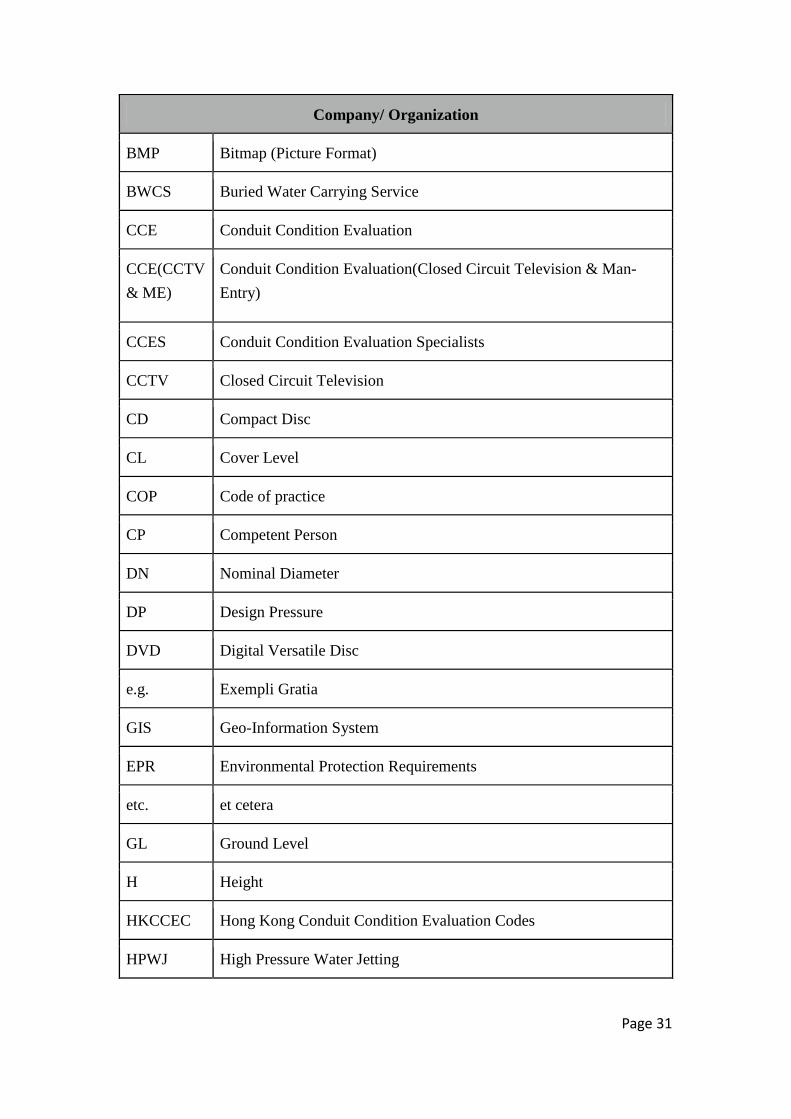
Company/ Organization
BMP Bitmap (Picture Format)
BWCS Buried Water Carrying Service
CCE Conduit Condition Evaluation
CCE(CCTV
& ME)
Conduit Condition Evaluation(Closed Circuit Television & Man-
Entry)
CCES Conduit Condition Evaluation Specialists
CCTV Closed Circuit Television
CD Compact Disc
CL Cover Level
COP Code of practice
CP Competent Person
DN Nominal Diameter
DP Design Pressure
DVD Digital Versatile Disc
e.g. Exempli Gratia
GIS Geo-Information System
EPR Environmental Protection Requirements
etc. et cetera
GL Ground Level
H Height
HKCCEC Hong Kong Conduit Condition Evaluation Codes
HPWJ High Pressure Water Jetting
Page 32
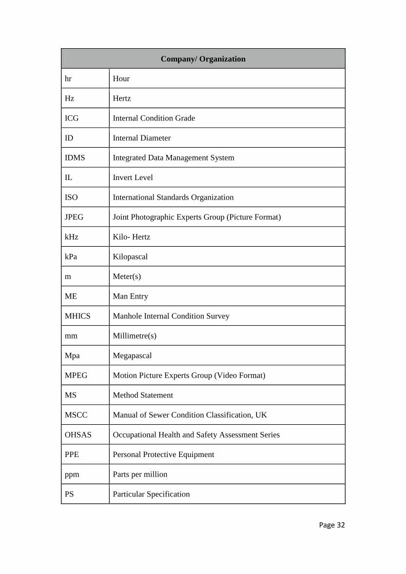
Company/ Organization
hr Hour
Hz Hertz
ICG Internal Condition Grade
ID Internal Diameter
IDMS Integrated Data Management System
IL Invert Level
ISO International Standards Organization
JPEG Joint Photographic Experts Group (Picture Format)
kHz Kilo- Hertz
kPa Kilopascal
m Meter(s)
ME Man Entry
MHICS Manhole Internal Condition Survey
mm Millimetre(s)
Mpa Megapascal
MPEG Motion Picture Experts Group (Video Format)
MS Method Statement
MSCC Manual of Sewer Condition Classification, UK
OHSAS Occupational Health and Safety Assessment Series
PPE Personal Protective Equipment
ppm Parts per million
PS Particular Specification
Page 33
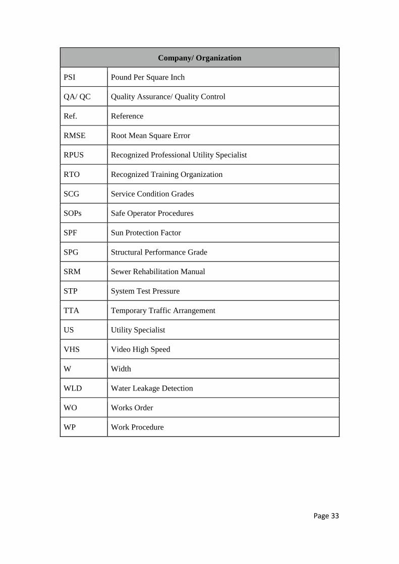
Company/ Organization
PSI Pound Per Square Inch
QA/ QC Quality Assurance/ Quality Control
Ref. Reference
RMSE Root Mean Square Error
RPUS Recognized Professional Utility Specialist
RTO Recognized Training Organization
SCG Service Condition Grades
SOPs Safe Operator Procedures
SPF Sun Protection Factor
SPG Structural Performance Grade
SRM Sewer Rehabilitation Manual
STP System Test Pressure
TTA Temporary Traffic Arrangement
US Utility Specialist
VHS Video High Speed
W Width
WLD Water Leakage Detection
WO Works Order
WP Work Procedure
Page 34
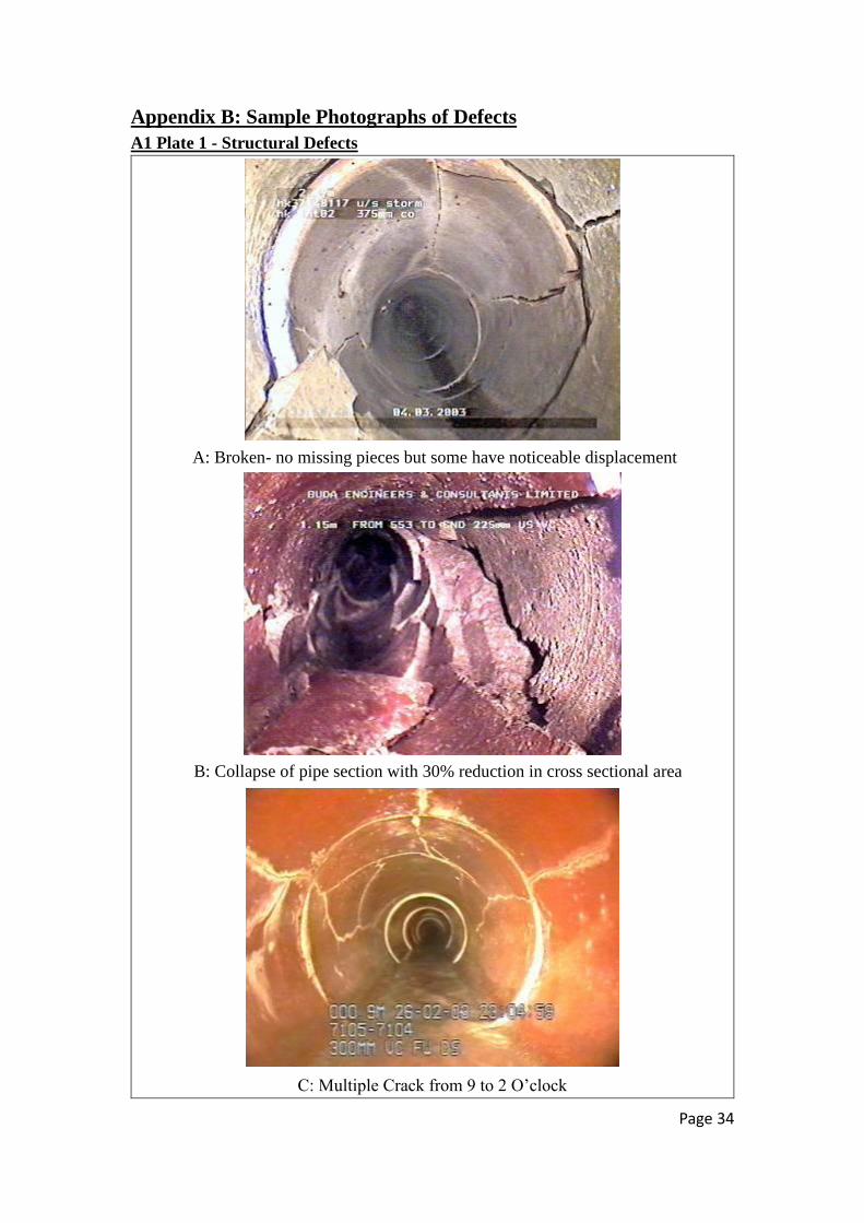
Appendix B: Sample Photographs of Defects
A1 Plate 1 - Structural Defects
A: Broken- no missing pieces but some have noticeable displacement
B: Collapse of pipe section with 30% reduction in cross sectional area
C: Multiple Crack from 9 to 2 O’clock

Page 35
D: Circumferential Fracture from 9 to 3 O’clock
E: Hole at 12 to 01 O’clock
F: The displaced joint appeared as a meniscus

Page 36
A2 Plate 2 - Service Defects
A: Deposit Attached- Foul material from the sewage attached to the inner wall of the pipe
B: Deposit Settled- Coarse material deposits at the bottom of the pipe
C: Encrustation- Heavy encrustation

Page 37
D: Infiltration- Groundwater running continuously through faulty joint
E: Obstruction- Boulders laying in the invert
F: Tree Root- Roots mass blocking over 80% of the cross –sectional area of the pipe

Page 38
A3 Plate 3 - Construction Defects
A: Connection- A connection at 12 O’clock with defects and is in service
B: Connection Defective- A connection intruding into the main pipe at 2 O’clock
Photos are adapted from HKCCEC 2009.
Page 39
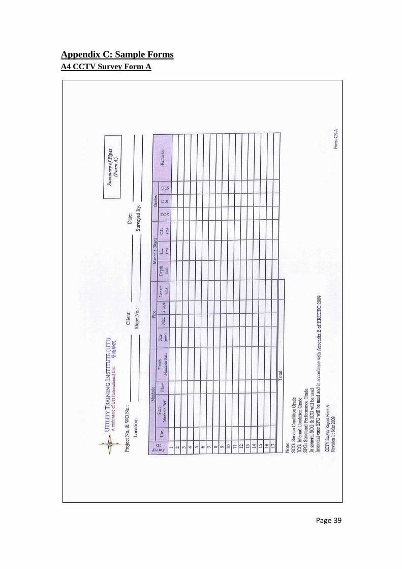
Appendix C: Sample Forms
A4 CCTV Survey Form A

Page 40
A5 CCTV Survey Form A (Filled)

Page 41
A6 CCTV Survey Form B

Page 42
A7 CCTV Survey Form B (Filled)

Page 43
A8 CCTV Survey Form C
Hand Report (Computer Generated with Defect Codes, Scores and Grades)

Page 44
A9 CCTV Survey Form C (Filled)

Page 45
A10 CCTV Survey Form C (Computerized)

Page 46
A11 CCTV Survey Form D
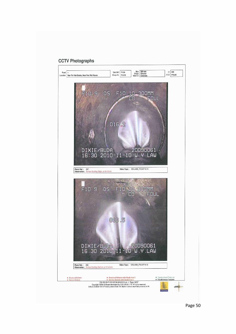
Defect or General Photos

Page 47
A12 CCTV Survey Form D (Filled)

Page 48

Page 49
Page 50
Page 51

Page 52