accumulators selection and design
DESCRIPTION
Accumulator selection and designTRANSCRIPT
PEMP – MMD 2516
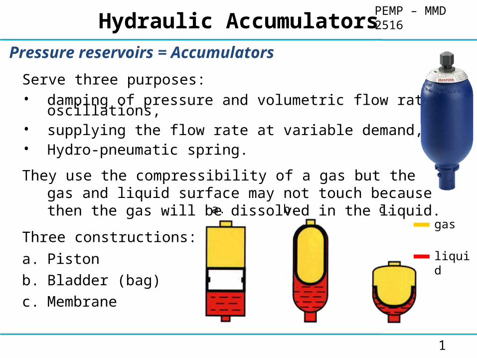
Pressure reservoirs = Accumulators
Serve three purposes:• damping of pressure and volumetric flow rate oscillations,• supplying the flow rate at variable demand,• Hydro-pneumatic spring.
They use the compressibility of a gas but the gas and liquid surface may not touch because then the gas will be dissolved in the liquid.
Three constructions:
a. Piston
b. Bladder (bag)
c. Membrane
gas
liquid
a. b. c.
1
Hydraulic Accumulators

PEMP – MMD 2516Accumulator Function
Accumulators have to carry out various functions in a hydraulic system•Energy storage•Fluid reserve•Emergency operation•Balance of forces•Damping of mechanical shocks•Damping of pressure shocks•Compensation of leakage oil•Damping of shocks and vibrations•Damping of pulses•Vehicle suspension•Reclaiming of deceleration energy•Maintaining constant pressure•Compensation of flow (expansion tank)
2
PEMP – MMD 2516Need of Accumulator
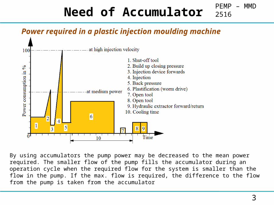
By using accumulators the pump power may be decreased to the mean power required. The smaller flow of the pump fills the accumulator during an operation cycle when the required flow for the system is smaller than the flow in the pump. If the max. flow is required, the difference to the flow from the pump is taken from the accumulator
3
Power required in a plastic injection moulding machine

PEMP – MMD 2516Hydraulic Accumulators
4

PEMP – MMD 2516Energy Storage in an Injection Moulding Machine
5
Several actuators with varying oil requirements

PEMP – MMD 2516Shorter Cycles
6
Energy storage in machine tools
Machine tools,By placing an accumulator directly in front of the actuator the inertia of the fluid column is overcome more quickly than it would be if all the fluid has to pass through the drive unit. Hence the system may be started up more quickly. In addition the accumulators equal out the varying fluid requirements of the actuators

PEMP – MMD 2516Decrease in time taken for a stroke
• In order to rationalize production in pressing operations, long and fast approach strokes are required in minimum time. The actual working process is then carried out at low velocity and at high pressure
• Under light running conditions, pump 1 (low pressure pump), pump 2 (high pressure pump) and the accumulator all deliver fluid, so that the desired high velocity is obtained
7
• As the pressure rises towards the end of the approach stroke, check valve (A) closes. Now only pump 2 delivers fluid with a low flow and at a high pressure. Pump 1 meanwhile recharges the accumulator.
PEMP – MMD 2516Fluid Reserve
• If the accumulator is used as a safety element, it does not operate as an energy source during normal operation of the system. It is however always connected directly to the pump. By using leak tight isolating elements, the stored energy may be held indefinitely and is immediately available if required.
• Safety systems using accumulators are used in hydraulic systems for emergency operation, in order to carry out specific actions when faults occur
• Some examples of actions to be undertaken are– Closing of partitions, flaps and switches
– Operation of sliding contacts
– Operation of high power switches
– Operation of quick shut-off systems
8

PEMP – MMD 2516Emergency Operation
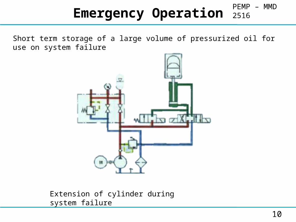
In emergencies eg., if power fails, a working or closing stoke is carried out with the help of the energy present in the accumulator. An example of the circuit for emergency operation is shown. If power fail, the spring causes valve 1 to close and return to original position. Hence the accumulator and piston rod side of the cylinders are connected. The oil under pressure in the accumulator causes the piston to retract.
9
Another application of emergency operation using accumulators is when an operating cycle which has started needs to be completed when a pump or valve malfunctionsThe main features of emergency operation using accumulators are•Direct availability•Unlimited endurance•No fatigue•No inertia•Highest safety achieved for little servicing
PEMP – MMD 2516Emergency Operation
10
Short term storage of a large volume of pressurized oil for use on system failure
Extension of cylinder during system failure
PEMP – MMD 2516Emergency Braking
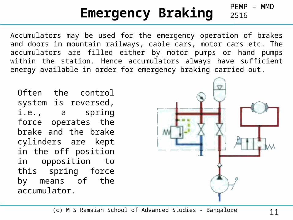
Accumulators may be used for the emergency operation of brakes and doors in mountain railways, cable cars, motor cars etc. The accumulators are filled either by motor pumps or hand pumps within the station. Hence accumulators always have sufficient energy available in order for emergency braking carried out.
(c) M S Ramaiah School of Advanced Studies - Bangalore 11
Often the control system is reversed, i.e., a spring force operates the brake and the brake cylinders are kept in the off position in opposition to this spring force by means of the accumulator.

PEMP – MMD 2516Emergency Lubrication
In order to maintain the lubricating film on bearings, these must be continually supplied with lubricating oil. This means that the lubricated positions are always under pressure. If the lubricating oil pump fails, the pressure can be kept constant by means of an accumulator until the machine has stopped or until a built in auxiliary pump has built up the required pressure.
12
Emergency operation of bearings
PEMP – MMD 2516Uninterrupted Operation Cycle
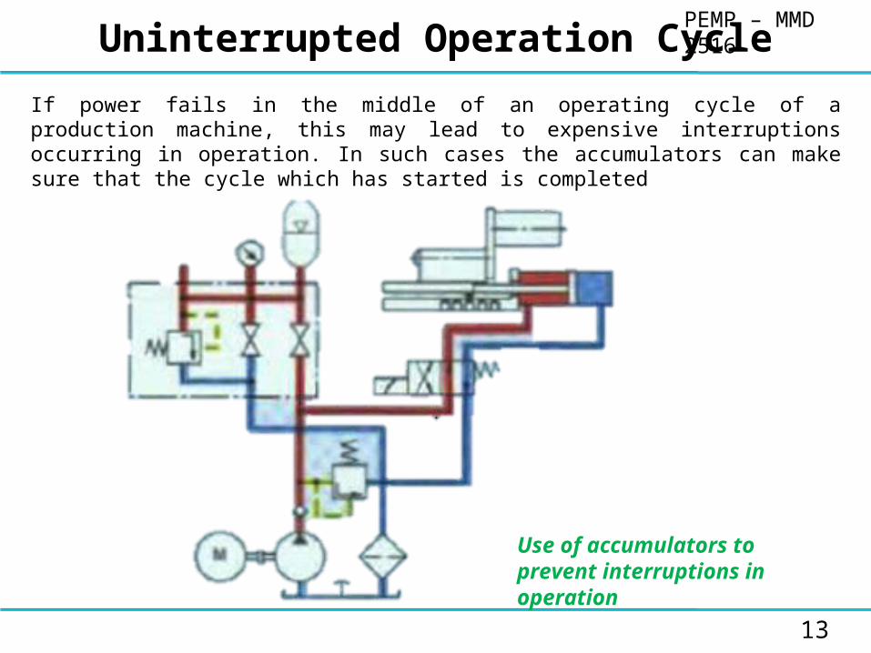
If power fails in the middle of an operating cycle of a production machine, this may lead to expensive interruptions occurring in operation. In such cases the accumulators can make sure that the cycle which has started is completed
13
Use of accumulators to prevent interruptions in operation

PEMP – MMD 2516Compensation of Forces
Forces or displacements in a continuous working process (rolling tilting may occur due to the varying load of the deformed material) may be compensated by using accumulators.
A circuit is shown for the counter balancing of a machine tool.
The following features must be mentioned.
Soft balancing of forces and hence low stressing on foundations and frame
Saving of counterweights and hence reduction in weight and space required for installations.
14
Balancing of rolls in the manufacture of sheet metal
PEMP – MMD 2516Compensation of leakage oil
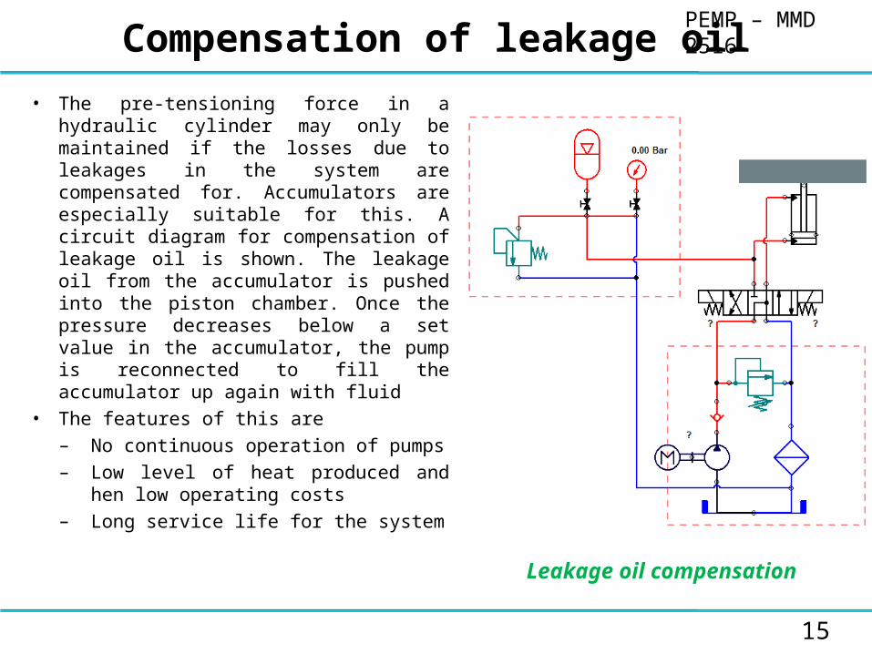
• The pre-tensioning force in a hydraulic cylinder may only be maintained if the losses due to leakages in the system are compensated for. Accumulators are especially suitable for this. A circuit diagram for compensation of leakage oil is shown. The leakage oil from the accumulator is pushed into the piston chamber. Once the pressure decreases below a set value in the accumulator, the pump is reconnected to fill the accumulator up again with fluid
• The features of this are
– No continuous operation of pumps
– Low level of heat produced and hen low operating costs
– Long service life for the system
15
Leakage oil compensation

PEMP – MMD 2516Damping of Shocks and Vibrations
• Pressure fluctuations may occur in hydraulic systems if the state of flow of the fluid changes due to varying processes dependent on the system
• Causes of this may include
– Non-uniformity within a hydraulic pump
– Spring mass systems (pressure compensators ion valves), abrupt connection of chambers with varying levels of pressure
– Operation of shut-off and control valves with short opening and closing times
– Connection processes involving distributor pumps
16
In conjunction with the above, flow and pressure fluctuations occur dependent on the operation which have a negative effect on the service life of all the components within a system
Accumulator as spring elements

PEMP – MMD 2516For positive displacement pumps
Depending on the type of displacement pump fluctuations may occur in the flow. These fluctuations can cause noise and vibrations to be produced. Hence the hydraulic system may be damaged.
Accumulators can be used as
1.Pulsation damping elements in positive displacement pumps
2.Pulsation damping elements in hydraulic systems with proportional or servo valves
3.Pulsation damping device downstream of pump
4.To dampen pressure shocks
5.Tensioning of chain in a machine tool
6.To tension of chain in cable cams
7.For vehicle suspension
8.To separate pneumatic part of the system from hydraulically operated part
9.To separate fluids
17

PEMP – MMD 2516Gas Accumulator with Separating Element
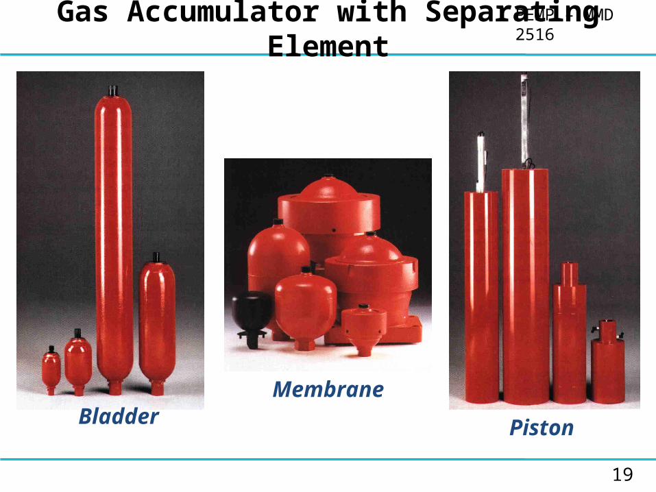
• Accumulators basically comprise a fluid compartment and a gas compartment with a gastight separating element. The fluid compartment is connected to the hydraulic circuit. As the pressure is increased the gas becomes compressed and the fluid is fed into the accumulator.
• The following types of accumulators with separating elements are used in hydraulic systems– Bladder accumulator
– Membrane accumulator
– Piston accumulator
18
PEMP – MMD 2516Gas Accumulator with Separating Element
MembraneBladder Piston
19

PEMP – MMD 2516Bladder Accumulators
• Bladder accumulator consists of a fluid compartment and a gas compartment with bladder being used as the gas tight separating element
• The fluid compartment surrounding the bladder is connected to the hydraulic circuit
• As the pressure is increased the bladder accumulator is filled and the gas is compressed. As the pressure is decreased, the gas expands and pushes the stored fluid into the circuit.
• Bladder accumulators may be installed horizontally, vertically or inclined (certain conditions).
• If the accumulator is installed vertically or at an angle the fluid valve must be situated at the bottom.
20
PEMP – MMD 2516Bladder Accumulators
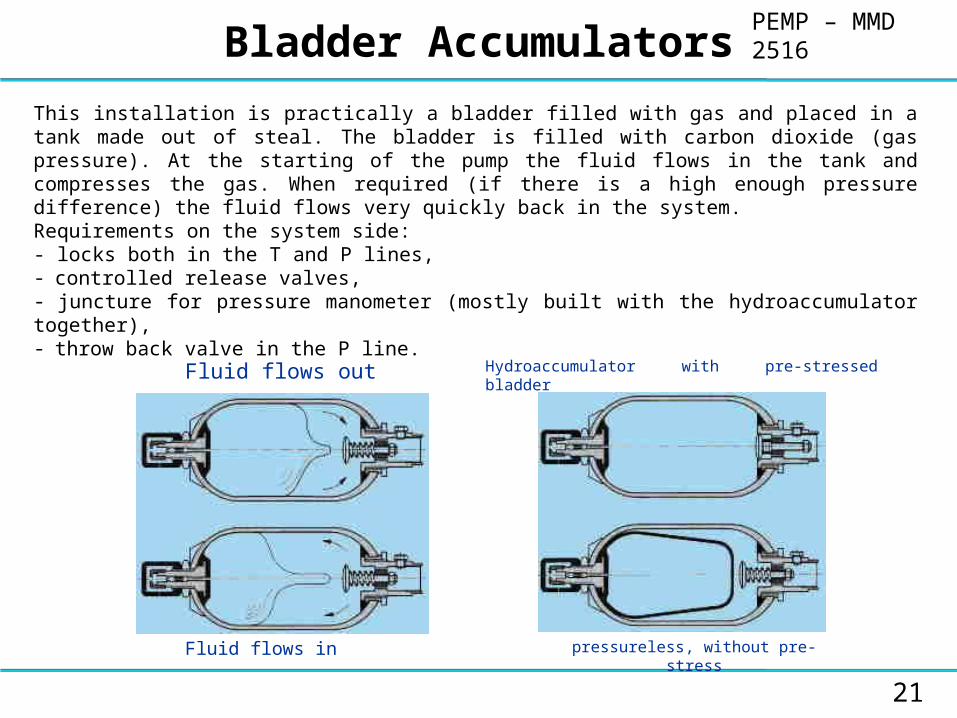
This installation is practically a bladder filled with gas and placed in a tank made out of steal. The bladder is filled with carbon dioxide (gas pressure). At the starting of the pump the fluid flows in the tank and compresses the gas. When required (if there is a high enough pressure difference) the fluid flows very quickly back in the system.Requirements on the system side:- locks both in the T and P lines,- controlled release valves,- juncture for pressure manometer (mostly built with the hydroaccumulator together),- throw back valve in the P line.
Fluid flows out
Fluid flows in
Hydroaccumulator with pre-stressed bladder
pressureless, without pre-stress
21

PEMP – MMD 2516Membrane Bladder
• Membrane accumulators comprise a steel container which is resistant to compression and is usually either spherical or cylindrical. Inside the accumulator is a membrane made of an elastic material (elastomer) and which is used as the separating element.
• There are two types of membrane accumulator available– Welded construction– Screwed construction
22
• In the welded model the membrane is pressed into the lower part before the circular seam welding is carried out.
• In the screwed model the membrane is held in position by screwing the top and bottom part to clamping nuts.

PEMP – MMD 2516Piston Type Accumulators
• Piston accumulators comprise fluid and gas compartments with a piston being used as the gas tight separating element
• The gas side is pre-filled with nitrogen• The fluid part is connected to the hydraulic
circuit. • As the pressure is increased the piston
accumulator is filled and the gas is compressed.
• As the pressure is decreased, the compressed gas expands and pushes the stored fluid into the circuit.
• Piston accumulators may be installed in any position.
• However the preferred position is the vertical one with the gas side at the top, so that deposits of dirt particles from the fluid on the piston seals are avoided.
23

PEMP – MMD 2516Addition of Pressure Containers
24
Additional pressure containers are recommended to be connected to the accumulator if there is only a small pressure difference between the max. and min. operating pressures and if large volume of gas is required for small effective volume.
PEMP – MMD 2516Accumulator Selection
25
• The following points needs to be taken into account when selecting the size of the accumulator required
• Volume expansion due to fluctuations in ambient temperature
• permissible pressure and volume ratio P2/P0 = V0/V2
• Effective volume

PEMP – MMD 2516Accessories for Accumulator
Safety and Isolating Control Blocks
•The safety and isolating control block is an accessory for protecting, isolating and unloading accumulators or hydraulics actuators
•This control block fulfills the safety requirements and acceptance standards in the countries in which it is used
26
• In particular, it passes the pressure container regulations with respect to pressure container equipment in accordance with the points mentioned in the technical regulations on pressure container.
Safety and isolating control block with manual unloading

PEMP – MMD 2516Accessories for Accumulator
27

PEMP – MMD 2516Accessories for Accumulator
28

PEMP – MMD 2516Accessories for Accumulator
• Normally nitrogen losses are very low in hydro-pneumatic accumulators
• However, in order to avoid the piston striking the cover and the bladder or membrane becoming too deformed, if the initial pressure P0 decreases, it is recommended that the gas pre-charge pressure is regularly checked
• By using the filling and testing unit, accumulators are filled with nitrogen or the initial nitrogen pressure available is altered
• For this purpose, the filling and testing unit is screwed onto the gas valve of the accumulator and connected to a standard nitrogen bottle via a flexible filing hose
• P0 has to be examined at regular intervals
29
Filling and testing procedure
Filling and testing kit

PEMP – MMD 2516Accessories for Accumulator
30
Portable and mobile Nitrogen charging device
• Nitrogen charging devices are used for quickly and economically filling nitrogen into accumulators. they make the most of standard nitrogen bottles up to a residual pressure of 20 bar and a max. accumulator loading pressure of 350 bar
• Hydro-pneumatic accumulators must be sufficiently protected and secured due to their weight and in addition due to the acceleration forces created by the fluid present in the accumulators. The securing of these accumulators must be such that no additional forces or torques are transferred by the accumulators to the hydraulic circuit.
Accumulator with fixing element
PEMP – MMD 2516Design of Hydro-Pneumatic Accumulators
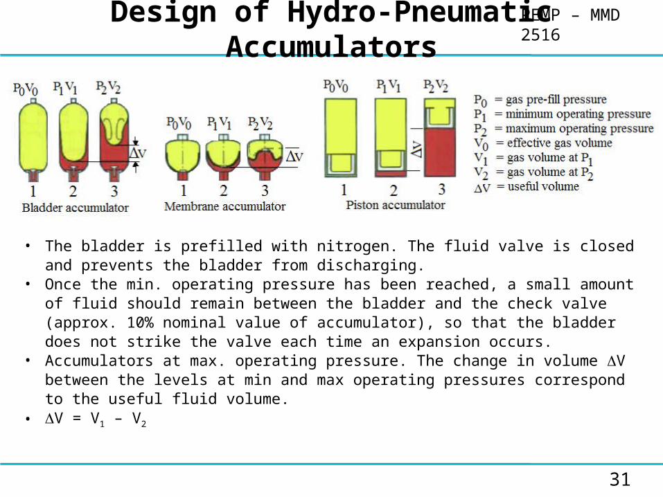
• The bladder is prefilled with nitrogen. The fluid valve is closed and prevents the bladder from discharging.
• Once the min. operating pressure has been reached, a small amount of fluid should remain between the bladder and the check valve (approx. 10% nominal value of accumulator), so that the bladder does not strike the valve each time an expansion occurs.
• Accumulators at max. operating pressure. The change in volume V between the levels at min and max operating pressures correspond to the useful fluid volume.
• V = V1 – V2
31

PEMP – MMD 2516Change of State in a Gas
Changes of state may be
– Isochoric process
– Isothermal process
– Adiabatic process
– Polytropic process
32
Since nitrogen does not behave as an ideal gas, it is recommended to use correction factors which take real gas behavior into account.
Volume produced in an isothermal change of state is given by V0 real = C1 V0 ideal
and in an adiabatic change of state by
V0 real = Ca V0 ideal
The correction factors C1 and Ca in these equation may be determined from manufacturers documentation.
PEMP – MMD 2516Determination of Accumulator Size
• The equations used for the design of an accumulator are dependent on the time required for the loading and unloading processes. As a rule of thumb, the following limits may be used to decide on which equation to use.– Cycle time < 1 minute adiabatic change of state
– Cycle time > 3 minutes isothermal change of state
– Cycle time between 1 and 3 minutes polytropic change of state
• Furthermore in designing an accumulator certain values found by experience must be adhered to in order to utilize the accumulator volume to an optimum extent and in order not to reduce the service life of the accumulator
33
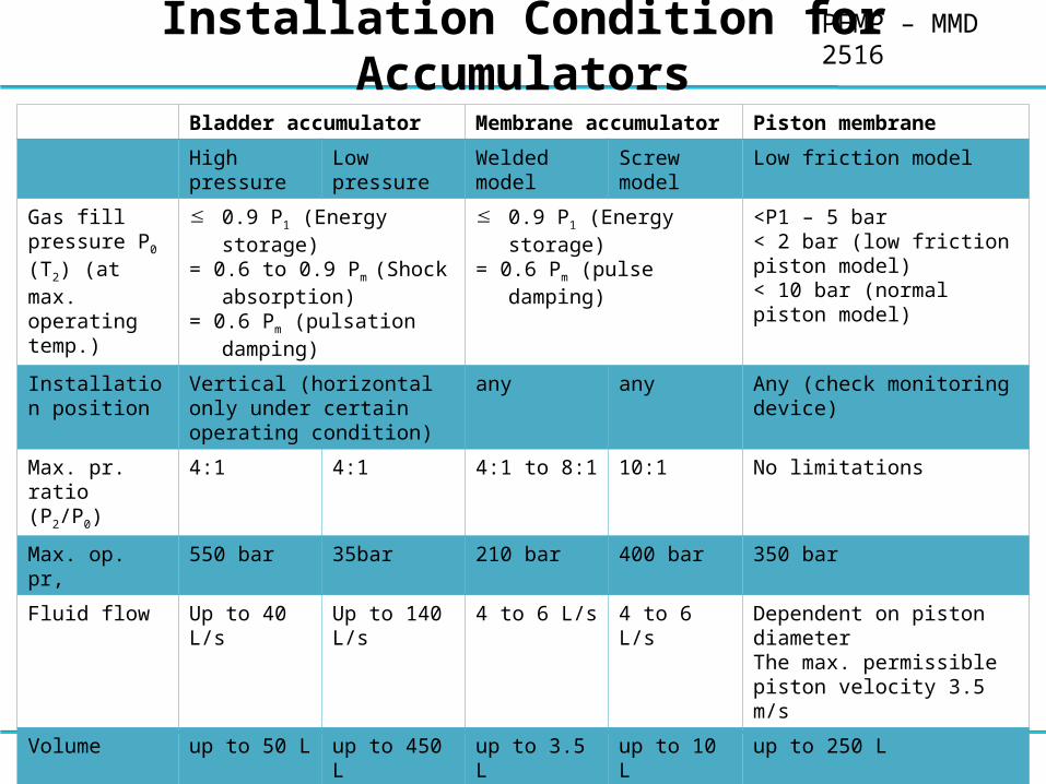
PEMP – MMD 2516Installation Condition for Accumulators
34
Bladder accumulator Membrane accumulator Piston membrane
High pressure Low pressure Welded model Screw model Low friction model
Gas fill pressure P0 (T2) (at max. operating temp.)
0.9 P1 (Energy storage)= 0.6 to 0.9 Pm (Shock
absorption)= 0.6 Pm (pulsation damping)
0.9 P1 (Energy storage)= 0.6 Pm (pulse damping)
<P1 – 5 bar< 2 bar (low friction piston model)< 10 bar (normal piston model)
Installation position
Vertical (horizontal only under certain operating condition)
any any Any (check monitoring device)
Max. pr. ratio (P2/P0)
4:1 4:1 4:1 to 8:1 10:1 No limitations
Max. op. pr, 550 bar 35bar 210 bar 400 bar 350 bar
Fluid flow Up to 40 L/s Up to 140 L/s 4 to 6 L/s 4 to 6 L/s Dependent on piston diameter The max. permissible piston velocity 3.5 m/s
Volume up to 50 L up to 450 L up to 3.5 L up to 10 L up to 250 L
General Replaceable bladderMonitoring possible under certain conditions
Replaceable bladderNo monitoring
Small gas and useful volumeCheap modelMembrane not replaceableNo monitoring
Small gas and useful volumeReplaceable membraneNo monitoring
Monitoring possibleInstall in preferred position for model with additional elementsReplaceable piston

PEMP – MMD 2516Basic Equation for Design of Accumulators
35
P0(T1) = Pre-fill pressure at min. temp. T1 in KP0(T2) = Pre-fill pressure at max. temp. T2 in KApplicationCalculation of pre-fill pressure for deviation of operating temperature from fill temperature
n = k = 1.4 for nitrogenP0 at T1
Application Energy Storage

PEMP – MMD 2516Basic Equation for Design of Accumulators
36
ApplicationEmergency function, safety function
(P0 at T1)
ApplicationLeakage oil compensationVolume compensation
(P0 at T1)
PEMP – MMD 2516Design Procedure
• In order to calculate and determine the relevant accumulator size, it is expected that the volume of fluid V and energy Q required to cover the needs are known. Taking into account other conditions such as
– max. operating pressure,
– max. and min. operating temperature
– operating pressure difference
• An accumulator is designed assuming initially that the change of state between operating pressures P1 and P2 is adiabatic. This limiting assumption is permitted as all the
requirements of the other changes of state will be fulfilled if calculations are made on this basis.
• By checking the calculation afterwards taking into account the time behavior and hence the deviation from the given adiabatic change of state, the design may be corrected (corrected factors Ca and C1 may be found in manufacturers documentation
• The pre-fill pressure (initially gas pressure) of the accumulator should be between 0.7 and 0.9 of the minimum operating pressure ( at max. operating temperature) P0(T2) 0.9P1
• By doing this, this avoids the accumulator separating element operating in the range of the fluid valve and hence avoids possible damage being done to it.
37

PEMP – MMD 2516Selection of Accumulator Type
Selection of type of accumulator for typical applications
•Membrane accumulator
They are used for small gas volumes. The advantage of a membrane accumulator is a good seal and long service life. They may be installed in any position and they operate without inertia.
•Bladder accumulator
Bladder accumulators are used for medium gas volumes and when accumulators need to deliver oil. Having improved the quality of the bladder in recent years, the bladder is now gas tight and has a long service life. Bladder accumulators are installed vertically to horizontally with the fluid outlet at the bottom or horizontally
•Piston accumulator
Piston accumulators are used in large gas volume. Piston accumulators are especially useful when adding gas bottles. The disadvantage of these accumulators is the weight of the separating pistons and hence the slower oil delivery of the accumulator, as well as the friction of the seals on the piston. This results in the useful pressure being reduced by as much as 10%. When loading and unloading a piston velocity of 2 m/s should not be exceeded. Piston accumulators may be installed in any position
38