accu-sort model 20 user manual
TRANSCRIPT

Model 20 Series IIBar Code Scanner
OPERATIONS AND MAINTENANCE MANUAL
Revision: 2.2 Release Date: 12/02


Accu-Sort Systems Addendum 1
Product Addendum
Model 20 Operations ManualModel 22 Operations Manual
Date: 8/7/00Filename: ecn4681_add.doc
ECN: 4681Writer: ERZ
IntroductionThis addendum documents an additional mounting option for yourModel 20 and 22 laser scanners. This information supersedes anysimilar information in your manual.
SpecificationsThis new mounting assembly p/n 100499 can be used to mount theModels 20 and 22 to any structure. It is shown below with a Model10. To use the 100499 with a Model 20 an M26B is required. To usewith a Model 22, a MDL22-8B is required.

Addendum 2 Accu-Sort Systems

I
INTRODUCTION
This is the Operations and Maintenance Manual for the Model 20. It providesdetails on everything you need to know to unpack, set up, operate, and maintainyour system.
This note box is used throughout this manual to indicate supplementaryinformation important to the current topic.
This document does not provide detailed information about any equipment usedin or with this system that Accu-Sort Systems does not manufacture.
This manual is not a troubleshooting or service procedure guide. Customers canpurchase technical service training directly from Accu-Sort. Direct any questionsabout detailed troubleshooting or service to the Accu-Sort Systems CustomerService Department.
MANUAL REVISIONS
This Operations and Maintenance Manual is under revision control. Any addendaor other documents associated with this manual are under separate revisioncontrols. A revision number is changed by 0.1 whenever technical information ischanged or added to a document. Any revision less than 0.1 is automaticallyconsidered preliminary. Any document with a revision 1.0 or greater has beenofficially released by the Accu-Sort Systems ECN process. The documentrevision history can be found in the Revision History section at the end of thismanual.
DISCLAIMER
Information in this manual is subject to change without notice. No part of thisdocument is to be reproduced or utilized in any form or by any means, electronicor mechanical, including photocopying, recording, or by an information storageand retrieval system without the prior written consent of Accu-Sort Systems, inc.All drawings and specifications contained in this manual are the property ofAccu-Sort Systems, inc. and shall not be reproduced, copied or used in whole orin part as the basis for the sale or manufacture of devices without writtenpermission.
Copyright© 2000 Accu-Sort Systems, inc.All Rights Reserved

II
WARRANTY
Accu-Sort Systems, inc. warrants that its scanner and component parts will befree from defects in material and workmanship for a period of one year from thedate of shipment (15 months for distributors to account for stocking of units). Allnew replacement units will also be warranted for the remainder of the originalone-year time period. Unless otherwise stated, warranty for products notmanufactured by ASI is limited to the manufacturer’s warranty. Accu-Sort’s soleobligation with respect to damage (whether direct, incidental or consequential,resulting from the use or performance of the unit) is to replace the defective unitsthereof.
Service requests due to misuse, abuse, neglect, changes in the originalspecifications, or service calls not related to the Accu-Sort equipment, will becharged at the then current service rate plus all travel related expenses.
• If the unit fails within two weeks of shipping (Out Of Box Failure):Standard units and custom units with only custom software are replaced within48 hours with new units. Units with custom hardware will be replaced in 72hours with new units. If the defective unit is not returned within 30 days, thecustomer will be contacted. If the defective unit is not returned after 45 days,the customer will be invoiced for that unit. Accu-Sort will issue an RA#(return authorization number) for each defective unit.
• If the unit fails after two weeks of shipment, but before the end of thewarranty period:
These procedures are the same as Out Of Box Failures, except Accu-Sort willsend refurbished units instead of new units. These refurbished units will bewarranted for 90 days from date of shipment or the balance of the original one-year warranty, whichever is greater.
• If the unit fails after the original warranty period (Out Of WarrantyFailures):
These procedures are the same as Out Of Box Failures, except Accu-Sort willsend refurbished units instead of new units. These refurbished units will bewarranted for 90 days from date of shipment. All out of warranty defectiveunits will be replaced for a fixed price. Contact the Accu-Sort CustomerService Department for the current prices.
Additional details on the coverage, support, and services available for your barcode scanning and automated systems equipment is available from:
Accu-Sort Systems, inc.2800 Crystal Drive 511 School House Road 2398 North Penn RoadHatfield, PA 19440 Telford, PA 18969 Hatfield, PA 19440
Phone: (215) 723-09811-800-BAR-CODE
FAX:
Internet: www.accusort.com
Telford Main ..........(215) 721-5551Customer Service ...(215) 723-1515Systems ..................(215) 996-8181Sales .......................(215) 996-8282Acct/Mktg ..............(215) 996-8249TMS .......................(215) 996-8787North Penn .............(215) 997-4848

III
CUSTOMER SERVICE
If you have any problems or questions that require Accu-Sort’s help, direct yourcalls to the Customer Service Department.
Accu-Sort Customer Service: phone: (215) 723-09811-800-BAR-CODE(ask for Customer Service)
fax: (215) 723-1515
To ensure that Accu-Sort’s response is prompt and accurate, please have thefollowing information ready to give the Customer Service Department whencalling:
• Product Serial Number• Product Type or name• Detailed description of the question or problem• Customer contact name and phone number
Product Type Serial Number
Model 20 Serial Tag
Serial Number Breakdown:WWXXXXXX (YY...)
WW - Two digit year of manufactureXXXXXX - Six digit sequential build number
Y - Optional suffix(es) that reflect actual catalog options for theoff-the shelf units
Model 20 Suffix Interface Box Suffix Add OnsA Standard A Without relays Z CustomB High Density B With relays ZR1 Custom 1@10 RasterC High Speed ZR2 Custom 1/2@10 Raster
- ex: M20A would have "A" as suffix- at least 6 digits can be placed on the tag- if "Z" is called out, this indicates a custom unit
requiring folder- could be used for special designations
The WWXXXXXX fields are bar coded with a Code 128 type bar code.

IV
SAFETY RECOMMENDATIONS AND PRECAUTIONS
The Model 20 is an electronic microprocessor-based imaging unit. Please followthe safety precautions and warnings found throughout this manual in order toprevent personal injury or damage to the unit. Failure to follow these precautionsmay void your warranty.
The following note boxes are displayed throughout this manual to indicate safetyconcerns and/or warnings.
This note box is used to provide precautions and/or guidelines, warning the userthat personal injury or damage to the unit may occur during the task they areperforming.
This note box is used to alert the user they are about to perform an actioninvolving a dangerous level of voltage, or to warn against an action that couldcause electrical shock.
Measures must be taken to prevent Electrostatic Discharge (ESD) at all timeswhen the cover is off the Model 20. Circuit Boards are at the most risk. See SafetyRecommendations and Precautions - Electrostatic Discharge.
This equipment has been tested and found to comply with the limits for a Class A digitaldevice, pursuant to part 15 of the FCC Rules. These limits are designed to provide reasonableprotection against harmful interference when the equipment is operated in a commercialenvironment. This equipment generates, uses, and can radiate radio frequency energy and, ifnot installed and used in accordance with the instruction manual may cause harmfulinterference to radio communications. Operation of this equipment in a residential area islikely to cause harmful interference in which case the user will be required to correct theinterference at his own expense.
WHEN UNPACKING AND MOUNTING
• Do not drop the unit• Do not touch the exit window glass
WARNINGThis is a Class A product. In a domestic environment this product can cause radiointerference in which case the user may be required to take adequate measures.(ref. CISPR 22 = EN 55 022:1995)
WARNINGIn order to maintain Electromagnetic Compatibility (EMC) Complianceinterconnecting cables must be connected using a 360° shield connection of allthe interface cables with a conductive strain relief for RF shielding purposes(I.e.:'metalized' 'D' sub-strain relief). This applies to all I/O cables connectedthrough 'D' sub-connectors.
WARNINGIf for any reason your Model 20 does not work, do not attempt to open the unit. TheModel 20 is designed to be returned to the factory for repair/replacement.

V
GENERAL PRECAUTIONS
Please follow these precautions:
• Avoid staring at the laser beam. Staring at the laser beam for prolongedperiods could result in eye damage.
• Do not create any obstructions of airflow to the unit. Keep the area aroundthe unit clean to provide for cooling.
• Any service should be performed so as not to violate compliance with theCode of Federal Regulations, Title 21, Part 1040, Section 10 (21 CFR1040.10), as administered by the Center for Devices and RadiologicalHealth, a service of the Food and Drug Administration under the Departmentof Health and Human Services. Do not attempt to defeat any safetyprovisions.
• Learn where the disconnect switches or circuit breakers are for your area.(Ensure that others using the equipment know this also.)
• Use shielded interface cables with this product. To maintain FCCcompliance, the cable shield must make a 360�������������������������mating connector.
• Before performing any type of maintenance, turn off power to the unit anddisconnect the power source.
• Be certain your hands and the floor of your work area are dry beforetouching electrical equipment or connecting cords.
• Routinely check all connections to your Model 20. If a cable is damaged inany way, replace it.
• Routinely examine all wiring and plugs for any signs of exposed wire ordeteriorating insulation.
• Check mounting hardware periodically for tightness and stability.• Do not use sheet rock or wood as a mounting surface for the Model 20. Use
steel or aluminum as a mounting structure.
LASER SAFETY
To prevent possible exposure to laser light that may exceed the CDRH’sAccessible Emission Limit for a Class II laser, your Model 20 has a “ScanningSafeguard” feature which shuts off the laser power if the mirror wheel fails torotate. This ensures that a stationary laser beam cannot exit the scan head.
The following software command has been provided as an alternate to the beamattenuator. When <ESC><ESC><ESC> is sent to the scanner, it causes the unitto turn the laser off. The commands 1600 (save), 1602 (abort), or 1603 (use) willcause the laser to turn back on.
The use of optical instruments with this product will increase eye hazard. Do notlook into the laser beam with instruments such as telescopes, binoculars, orcameras.
Use of controls or adjustments or performance of procedures other than thosespecified herein may result in hazardous laser light exposure.

VI
GROUNDING THE MODEL 20
The system must be grounded electrically at all times. Please follow theseprecautions:
• Ensure your AC power outlet has a properly grounded receptacle.• Make sure you have the appropriate power cord for your country before
turning on the unit.• Do not turn on the system until all components are properly cabled and
grounded with three-conductor AC power cords. Do not use a two-prongadapter.
• Do not cut or remove the round grounding prong from the plug under anycircumstances.
• Do not use an extension cord to defeat the ground.
ELECTROSTATIC DISCHARGE
Electrostatic discharge (ESD), the transfer of static electricity from one object toanother, is an often-unnoticeable hazard to electronic components. Boards andother devices with integrated circuits are particularly sensitive to ESD damage.Product failures may not occur until days or weeks after the component wasdamaged.
Static damage to components can take the form of upset failures or catastrophicfailures (direct and latent).
An upset failure occurs when an electrostatic discharge is not significant enoughto cause total failure, but may result in intermittent gate leakage, causing loss ofsoftware or incorrect storage of information.
Direct catastrophic failures occur when a component is damaged to the pointwhere it is permanently damaged.
The following note box is displayed where ESD precautions must be followed:
Measures must be taken to prevent Electrostatic Discharge (ESD) at all timeswhen the cover is off the Model 20. Circuit Boards are at the most risk. See SafetyRecommendations and Precautions - Electrostatic Discharge.
Five Basic Rules for ESD Control
Below are some keys to effectively control unnecessary ESD damage. Whenworking with ESD-sensitive devices:
• Define an ESD protective area and work on the ESD-sensitive devices in thisarea only;
• Define the sensitivity of devices to be handled in the ESD protective area;• Establish a suitable static control program that both limits static generation to
less than the damage threshold of the most sensitive device in theenvironment, and provides a safe, defined path for the dissipation of staticcharges;
• Prevent contamination of the protective area by unnecessary non-staticcontrolled materials; and
• Audit the ESD protective area regularly to ensure that static control ismaintained. Document the findings for future reference.

VII
LABEL LOCATIONS
The following labels identify areas of the Model 20 that require specialprecautions or handling, or provide general information.
Label Locations

VIII

Solutions with Vision
Chapter OneGetting Started With Your Model 20
ABOUT THE MODE L 20................................................................................................................................. 1-3PRODUCT SPECIFICATIONS........................................................................................................................... 1-4DECODING BAR CODES ................................................................................................................................ 1-5HOW YOUR MODEL 20 SCANNING SYSTEM WORKS ....................................................................................... 1-6
EXAMPLES OF LED FUNCTIONALITY................................................................................................. 1-7CHECKING THE PACKING SLIP....................................................................................................................... 1-8
Chapter TwoWhat To Do After Receiving Your Model 20
MOUNTING YOUR MODEL 20......................................................................................................................... 2-3CLIPS ............................................................................................................................................. 2-3MOUNTING PLATE ........................................................................................................................... 2-4LADDER MOUNTING BRACKET.......................................................................................................... 2-5PICKET FENCE MOUNTING BRACKET................................................................................................ 2-6CRADLE MOUNTING BRACKET.......................................................................................................... 2-7
MOUNTING THE PHOTOEYE........................................................................................................................... 2-8SETTING UP YOUR MODEL 20 .................................................................................................................... 2-10
Chapter ThreeConnecting Your Model 20 to an External Device
CONNECTING YOUR MODEL 20 TO THE INTERFACE BOX ................................................................................ 3-3IF THE INTERCONNECT CABLE IS NOT AVAILABLE.............................................................................. 3-3
CONNECTING YOUR MODEL 20 TO OTHER EXTERNAL DEVICES...................................................................... 3-4RS232 WITH NO HANDSHAKING ...................................................................................................... 3-4RS422 (POINT-TO-POINT) ............................................................................................................... 3-5RS485 MULTIDROP ........................................................................................................................ 3-5CONNECTING YOUR MODEL 20 TO A PC .......................................................................................... 3-6CONNECTING YOUR MODEL 20 TO A TERMINAL ................................................................................ 3-8
SUPPLYING POWER TO YOUR MODEL 20....................................................................................................... 3-9USING THE SMALL SCANNER INTERFACE BOX FOR POWER ............................................................... 3-9USING ACCU-SORT’S LOCAL POWER SUPPLY FOR POWER.............................................................. 3-10WIRING OTHER SOURCES OF POWER DIRECTLY............................................................................. 3-11
SUPPLYING A TRIGGER INPUT TO YOUR MODEL 20 ...................................................................................... 3-12USING MODEL 20 PARALLEL OUTPUTS ....................................................................................................... 3-13
HOW THE OUTPUTS WORK ............................................................................................................ 3-13PARALLEL OUTPUT CONNECTIONS................................................................................................. 3-14
Table of Contents

MODEL 20 OPERATIONS AND MAINTENANCE MANUAL
Accu-Sort Systems
Chapter FourMaintaining and Troubleshooting Your Model 20
INTRODUCTION............................................................................................................................................. 4-3CLEANING PROCEDURE ................................................................................................................................ 4-3TROUBLESHOOTING YOUR MODEL 20 ........................................................................................................... 4-4
PROBLEM/SOLUTION TABLE............................................................................................................. 4-5
Appendix AASCII Communications
ASCII COMMUNICATIONS .............................................................................................................................A-3STANDARD RS485 MULTIDROP COMMUNICATIONS...........................................................................A-3MESSAGE FORMATS........................................................................................................................A-4MESSAGE SEQUENCING ..................................................................................................................A-5TIMING ...........................................................................................................................................A-5MULTIDROP PROTOCOL EXAMPLES..................................................................................................A-7PROTOCOLS USED WITH RS232, CURRENT LOOP, AND 422 ............................................................A-8
ASCII CHART ..............................................................................................................................................A-9
Appendix BRead Rate Charts
STANDARD SCAN HEAD................................................................................................................................B-3HIGH SPEED SCAN HEAD ..............................................................................................................................B-4HIGH DENSITY SCAN HEAD...........................................................................................................................B-5
Appendix CPart Numbers
PART NUMBERS ...........................................................................................................................................C-3
Glossary
Index
Revision History

MODEL 20 SERIAL TAG ................................................................................................................................... IIILABEL LOCATIONS..........................................................................................................................................VIIMODEL 20 STATUS LED LOCATION .............................................................................................................. 1-6PARTS TABLE............................................................................................................................................... 1-9MOUNTING THE MODEL 20 USING MOUNTING CLIPS ...................................................................................... 2-3MOUNTING THE MODEL 20 USING THE MOUNTING PLATE............................................................................... 2-4MOUNTING THE MODEL 20 USING THE LADDER MOUNTING BRACKET ............................................................. 2-5MOUNTING THE MODEL 20 USING THE PICKET FENCE MOUNTING BRACKET ................................................... 2-6MOUNTING THE MODEL 20 USING THE CRADLE BRACKET .............................................................................. 2-7PHOTOEYE MOUNTING DIAGRAM .................................................................................................................. 2-8PHOTOEYE MOUNTING DIAGRAM .................................................................................................................. 2-9INTERCONNECT CABLE ................................................................................................................................. 3-3PINOUTS FOR THE CONNECTIONS BETWEEN THE INTERFACE BOX AND THE MODEL 20 .................................... 3-3MODEL 20 PROGRAMMING KIT ..................................................................................................................... 3-6MODEL 20 TO PC CONNECTIONS.................................................................................................................. 3-7TERMINAL TO ACCU-SORT DEVICE CONNECTIONS ......................................................................................... 3-8INTERCONNECT CABLE ................................................................................................................................. 3-9ALTERNATIVE WIRING METHODS FOR SUPPLYING POWER TO THE MODEL 20................................................ 3-11TWO DIFFERENT WAYS TO WIRE A TRIGGERING DEVICE TO YOUR MODEL 20 (TOP TTL METHOD, BOTTOM-DRY
CONTACT METHOD) ............................................................................................................................ 3-12OUTPUT CONNECTIONS.............................................................................................................................. 3-14MODEL 20 OUTPUT CIRCUITRY................................................................................................................... 3-14RS485 COMMUNICATIONS EXAMPLE ............................................................................................................A-3MASTER/SLAVE TIMING DIAGRAM .................................................................................................................A-5ASCII CHART ..............................................................................................................................................A-9
Table of Figures

MODEL 20 OPERATIONS & MAINTENANCE MANUAL
Accu-Sort Systems

Chapter One Contents
Chapter OneGetting Started With Your Model 20
1Heading 2
ABOUT THE MODE L 20 ............................................................................. 1-3
PRODUCT SPECIFICATIONS ........................................................................ 1-4
DECODING BAR CODES ............................................................................. 1-5
HOW YOUR MODEL 20 SCANNING SYSTEM WORKS .................................... 1-6
EXAMPLES OF LED FUNCTIONALITY....................................................... 1-7
CHECKING THE PACKING SLIP ................................................................... 1-8

1-2 MODEL 20 OPERATIONS AND MAINTENANCE MANUAL
Accu-Sort Systems

GETTING STARTED WITH YOUR MODEL 20 1-3
Solutions with Vision
ABOUT THE MODE L 20
Accu-Sort presents the Model 20 Bar Code Scanning System, one of the smallestcomplete scanning systems available. Most bar code scanning and decodingapplications need an external decoder/logic unit and a remote scanning head. TheModel 20, however, has a built-in decoder/logic.
Accu-Sort Systems developed the Model 20 with the various needs of theircustomers in mind. Because of this, the Model 20 is designed with manypowerful features that make bar code scanning easier to implement and maintain.The standard features include:
• RISC Processor• Operator LED indicators• Autodiscrimination of bar code symbologies• Preset scanning distances for a wide variety of code densities• Automatic Laser Control (ALC) to automatically adjust for deviations in bar
code color, quality, and reflectance
Optional features designed to enhance the performance of the Model 20 are alsoavailable. These features include:
• High Density scanning• Accu-Sort’s patented DRX technology• High speed scanning (700 scans per second)
If your unit uses Accu-Sort’s patented DRX technology, the following patentnumbers apply:

1-4 MODEL 20 OPERATIONS AND MAINTENANCE MANUAL
Accu-Sort Systems
PRODUCT SPECIFICATIONS
PhysicalSize 2.34" L (59.4 mm) x 2.12" W (53.8 mm) x 1.41" H (35.8 mm)
Weight 5 oz. (140 grams)
Enclosure NEMA 12 standard(gasketed, drip-proof and dust-tight)
Visual Diagnostics One multifunction LED that indicates Power, Object Detection,Laser and Go/No Read
EnvironmentalTemperature Range 32 to 104°F (0 - 40°C)
Operating ParametersPower Requirements 500 mA at 5 VDC
Radiant Power Output <5.0 mW (650nm)
Scan Rate 500 scans per second (standard); 300 scans per second (highdensity and long range); 700 scans per second (high speed)
Scanning Range 1" (25.4mm) to 12" (304.8mm)
Bar Code Types All standard 1D symbologies
Communications RS232, RS422, RS485, Current loop (with interface box option),and programmable I/O

GETTING STARTED WITH YOUR MODEL 20 1-5
Solutions with Vision
DECODING BAR CODES
The Model 20 scans a bar code, turns the reflected light into electronic signalsand then amplifies the signals. It then converts the analog signal to digital pulses.
The Model 20 is designed with a powerful RISC (Reduced Instruction SetComputer) processor. The RISC processor determines the width of each bar andspace based on the time it took the laser to sweep across each of the elements inthe bar code.
The Model 20 transmits the decoded bar code information to a CRT or hostcomputer.

1-6 MODEL 20 OPERATIONS AND MAINTENANCE MANUAL
Accu-Sort Systems
HOW YOUR MODEL 20 SCANNING SYSTEMWORKS
As soon as you set up and install your Model 20 as discussed in the remainingchapters of this manual, it is ready to read bar codes.
The Model 20 has one multi-color LED indicator at the rear of the unit thatprovides you with operational information. The location of this LED is shown inthe following drawing. The LED provides status on power (idle), trigger (cartonpresence), good read, no read or non-valid code (NVC), and failure. Thefollowing are descriptions of each LED.
LED ACTION STATUS DESCRIPTIONBlinking Yellow Idle Model 20 has power, is not triggered, and is
functioning normallySolid Yellow Trigger Model 20 laser is on, and either the trigger input is
active or the unit is in continuous read modeGreen for ½ second Good Read Model 20 has successfully decoded a bar codeSolid red for ½ second No Read Model 20 was not successful in decoding a bar
code, or a non valid bar code was detectedFlashes in red, yellow,green sequence
ConfirmingSetup Mode
Model 20 is in setup mode
Solid red for an extendedperiod of time or blinking red
Failure Model 20 has detected a malfunction or is notfunctioning up to specifications (in either of thesecases, contact Accu-Sort)
For additional information see the Problem/Solution list in Chapter 4(Troubleshooting).
Model 20 Status LED Location

GETTING STARTED WITH YOUR MODEL 20 1-7
Solutions with Vision
EXAMPLES OF LED FUNCTIONALITY
The following are two scenarios of how the Model 20 Status LED works:
When your Model 20 is programmed for Hardware or Serially Controlled Trigger(Refer to your Accu-Setup Suite Small Scanner Module Programming Manual),the following sequence of events should occur:
1. When the Model 20 is supplied with power, and nothing triggers the unit, thestatus LED blinks yellow.
2. When the trigger signal is activated (example; a box blocks the photoeye),the status LED turns to solid yellow for the amount of time the box blocksthe triggering device.
Solid yellow always indicates that the laser is on.
Then:
• the status LED changes to green for 1/2 second if the Model 20 successfullydecodes the bar code
-OR-• the status LED changes to red for 1/2 second if the Model 20 does not
successfully decode the bar code
3. The status LED changes back to blinking yellow until the trigger signal(could be a serial character or hardware transition) is activated again.
When your Model 20 is programmed for Continuous Read (refer to your Accu-Setup Suite Small Scanner Module Programming Manual), the followingsequence of events should occur:
The Model 20 ignores any trigger input, hardware or serial.
1. When the Model 20 is supplied with power, the status LED blinks yellow forabout five seconds, then it turns solid yellow, indicating read mode.
2. The status LED changes to green for 1/2 second every time the Model 20successfully decodes the bar code.
3. The status LED then changes back to yellow.
With this scenario, the status LED never turns red, because it does not knowwhen something passes in front of the Model 20.

1-8 MODEL 20 OPERATIONS AND MAINTENANCE MANUAL
Accu-Sort Systems
Enclosed in plastic on the outside of one of your boxes is a packing slip. Thepacking slip lists the parts of your order.
As soon as you open the box(es), check the equipment against the packing slip toensure you received everything you ordered. If any equipment is missing or hasbeen damaged during shipment, contact Accu-Sort immediately at 1-800-BAR-CODE (refer to Customer Service).
The Model 20 packaging was specifically designed to protect the unit duringshipment. Do not throw it away. Save all the packaging materials for possiblefuture use.
Depending upon your needs, you may have one or more of the pieces ofequipment shown in the following table:

GETTING STARTED WITH YOUR MODEL 20 1-9
Solutions with Vision
DRAWINGS ARE NOT TO SCALE
Part PartNumber Description
1000017344 Model 20 Custom Assembly1000017345 Model 20 Custom 1 @ 10 Raster Assembly1000017346 Model 20 Custom .5 @ 10 Raster Assembly
OTS Distributor Units1000025478 Model 20, Standard, Linear Decoding, 12 Sided Mirror1000025479 Model 20, Standard, DRX Decoding, 12 Sided Mirror1000025480 Model 20, Standard, Linear Decoding, .5@10 Raster1000025481 Model 20, High Density, Linear Decoding, 12 Sided Wheel1000025482 Model 20, High Density, DRX Decoding, 12 Sided Wheel1000025483 Model 20, High Density, Linear Decoding, .5@10 Raster1000025484 Model 20, High Speed, Linear Decoding, 12 Sided Wheel1000025485 Model 20, High Speed, DRX Decoding, 12 Sided Wheel1000025486 Model 20, High Speed, Linear Decoding, .5@10 Raster1000017362 Small Scanner Interface without relays1000017365 Small Scanner Interface with relays1000014575 Interconnect CableThe Small Scanner Interface connects to the Model 20 to provide a regulated 5 VDC. TheInterface also separates the power input, communication port and hardware trigger input intothree discrete connectors, making it easy to use the Model 20 with existing equipment withouthaving to wire these lines directly into the Model 20. Use the interconnect cable to connect theinterface box to the Model 20.1000020527 Photoeye
This is a photo-electric eye that sends a signal to the Model 20 when something blocks its pathof light. Photoeyes provide one way to trigger the Model 20 when an object arrives and when anobject leaves the scanner.
1000022163 110V AC Power Supply, connects to interface box only1000017359 110V AC Local Power Supply, connects to Model 20 only1000015618 220V AC Power Supply, connects to interface box only1000017360 220V AC Local Power Supply, connects to Model 20 only1000017384 Mounting Clips1000017383 Ladder Mounting Bracket1000017382 Picket Fence Mounting Bracket1000017379 Mounting Plate1000017380 Cradle Mounting Bracket
Five different mounting options are offered. All of the options depend on the type of applicationthey are to be used in.1000017381 110V AC Model 20 Programming Kit1000017382 220V AC Model 20 Programming Kit
The programming kit connects the Model 20 to a standard 9 pin serial port on the back of apersonal computer when setting-up the Model 20 software. The PC setup program is calledAccu-Setup. Refer to the Accu-Setup Suite Small Scanner Module Programming Manual fordetails about programming the Model 20. This kit can be used to provide only power and RS232communications, if no other signals are to be used in the application.
Parts Table
Be careful when making any electrical connections. Electric shock is possiblewhen making any contact with electricity.
Do not turn on the system until all components are properly cabled and groundedwith three-conductor AC power cords. Do not use a two-prong adapter. Do notuse an extension cord to defeat the ground.

1-10 MODEL 20 OPERATIONS AND MAINTENANCE MANUAL
Accu-Sort Systems

Chapter TwoWhat To Do After Receiving Your Model 20
2Heading 2
MOUNTING YOUR MODEL 20 .................................................................... 2-3
CLIPS .................................................................................................. 2-3MOUNTING PLATE ................................................................................ 2-4LADDER MOUNTING BRACKET .............................................................. 2-5PICKET FENCE MOUNTING BRACKET .................................................... 2-6CRADLE MOUNTING BRACKET .............................................................. 2-7
MOUNTING THE PHOTOEYE....................................................................... 2-8
SETTING UP YOUR MODEL 20 ................................................................ 2-10
Chapter Two Contents

2-2 MODEL 20 OPERATIONS AND MAINTENANCE MANUAL
Accu-Sort Systems

WHAT TO DO AFTER RECEIVING YOUR MODEL 20 2-3
Solutions with Vision
MOUNTING YOUR MODEL 20
When you mount your Model 20, make sure there is enough space around theunit for the connections to the accessories needed for your application. Theremust also be enough room to allow the Model 20 and its equipment to stay cool.The minimum space requirements for the Model 20 are as follows:
Minimum Space Requirements for MountingOverhead Enough room for air flow
Back 2.25" (5.7 cm) for connectionsSides Enough room for air flowFront No obstructions between the scanner and the bar code to be scanned during the
read cycle
There are many different ways to mount the Model 20. You can purchase thefollowing five pieces of equipment from Accu-Sort to mount the Model 20:
CLIPS
There are two mounting clips designed to hold the Model 20 in a position so thescan line is parallel to the mounting surface. Each clip has an oblong slotdesigned for a #6 mounting screw. The mounting screws are to be located 2.9"(7.37 cm) apart. Insert the mounting clips into the grooves on the sides of theModel 20, as shown below.
You can use any type of fasteners with these mounting brackets, as long as theyare compatible with the mounting surface.
To mount the Model 20:1. Fasten one clip to the mounting surface.2. Slide the clip into one of the grooves on the side of the Model 20.3. Place the remaining clip in the groove on the same level on the other side of
the Model 20.4. Fasten the remaining clip to the mounting surface. This ensures a tight mount
so the Model 20 does not have any room for movement during operation.
Mounting the Model 20 Using Mounting Clips

2-4 MODEL 20 OPERATIONS AND MAINTENANCE MANUAL
Accu-Sort Systems
MOUNTING PLATE
There is one mounting plate, one mounting clip, one #6-32 nut, and one #6internal tooth lockwasher included with this assembly. The mounting plate isdesigned to hold the Model 20 in position so the scan line is parallel to themounting surface. The plate is rectangular with an oval slot near corners. Theslots are designed for #6 mounting screws.
To mount the Model 20:1. Fasten the plate to the mounting surface.2. The plate has one fixed retaining clip, one #6-32 stud and one #6 nut that
holds the adjustable clip. Place the Model 20 in position so the slot on theside of the housing is engaged by the fixed clip.
3. Move the adjustable clip towards the Model 20 until it engages the other slotof the Model 20 housing.
4. Tighten the nut on the stud to secure the Model 20.
This ensures a tight mount so the Model 20 does not have any room formovement during operation, and it also allows you to remove the Model 20 andreplace it with the use of only one nut.
Mounting the Model 20 Using the Mounting Plate

WHAT TO DO AFTER RECEIVING YOUR MODEL 20 2-5
Solutions with Vision
LADDER MOUNTING BRACKET
The ladder mounting bracket is designed to hold the Model 20 in a position sothe scan line is perpendicular to the mounting surface. The bracket fits around theModel 20, but is not directly secured to the Model 20. Flanges on the bracketprovide oblong slots that are designed for #6 mounting screws on either side ofthe Model 20. Mounting screws need to be located 2.25" (5.7 cm) apart.
To mount the Model 20:1. Place the bracket around the Model 20 so the support of the bracket rests on
one of the sides of the Model 20, as shown below.2. Place the mounting bracket, with the Model 20 clamped inside, against the
mounting surface.3. Insert and tighten the mounting screws in the oblong slots on the bracket.
This ensures the Model 20 is secured within the bracket against the mountingsurface.
Mounting the Model 20 Using the Ladder Mounting Bracket

2-6 MODEL 20 OPERATIONS AND MAINTENANCE MANUAL
Accu-Sort Systems
PICKET FENCE MOUNTING BRACKET
The picket fence mounting bracket is designed to hold the Model 20 in a positionso the scan line is parallel to the mounting surface. The bracket fits around theModel 20, but is not directly secured to the Model 20. Flanges on the bracketprovide oval slots that are designed for #6 mounting screws on either side of theModel 20. Mounting screws need to be located 3" (7.62 cm) apart.
To mount the Model 20:1. Place the bracket around the Model 20 so the backing of the bracket rests on
top of the Model 20, as shown below.2. Place the mounting bracket, with the Model 20 clamped inside, against the
mounting surface.3. Insert and tighten the mounting screws in the oblong slots on the bracket.
This ensures the Model 20 is secured within the bracket against the mountingsurface.
Mounting the Model 20 Using the Picket Fence Mounting Bracket

WHAT TO DO AFTER RECEIVING YOUR MODEL 20 2-7
Solutions with Vision
CRADLE MOUNTING BRACKET
There is one cradle mounting bracket, one 2-1/8" #6-32 round spacer, two 3/8"#6-32 socket head cap screws, two #6 flat washers, and two #6 split lockwashersincluded with this assembly. The cradle-mounting bracket is designed to hold theModel 20 in a position so the scan line is parallel to the mounting surface. Four#6-32 pem nuts are provided on the bottom of the bracket.
The top edges on both sides of the cradle are bent at a 90-degree angle. Thisresults in two flanges that fit into the slots on the sides of the Model 20. There aresix slots on each side of the Model 20. Different sets of slots can be used with thefollowing results:
Bottom Slots Overall height (bracket and Model 20) 2.75"
Four up from bottom Overall height (bracket and Model 20) 2.05"
Mounting the Model 20 Using the Cradle Bracket

2-8 MODEL 20 OPERATIONS AND MAINTENANCE MANUAL
Accu-Sort Systems
MOUNTING THE PHOTOEYE
This section describes how to mount your photoeye to the photoeye mountingbracket. Photoeyes work by bouncing a light beam off a reflector and detectingwhen something breaks the path of light. In order for your photoeyes to workproperly, you must make sure the following things are done:
• The photoeye must have a reflector mounted directly opposite it on the otherside of the conveyor.
• The photoeye must be mounted so the light exit window is perpendicular tothe conveyor, facing the reflector.
• The reflector must be mounted perpendicular to the conveyor, facing thephotoeye.
Use the following drawings to help you mount your photoeye. The tables provideinformation pertaining to each item number in the drawing.
Photoeye Mounting Diagram
Use the following table to match item numbers with the photoeye mountingdiagram above:
QuantityRequired
Description PartNumber
ItemNumber
1 #8-32 Nut 1000018466 111 #8 Internal Tooth Lock Washer 1000016778 101 #8 Flat Washer 1000022114 91 3” Reflector 1000013792 81 8-32 2” Machined Pan HD 1000010689 71 Model 30 PE Mtg. Bracket 1000011711 62 #6-32 Nut 1000018459 52 #6 Internal Tooth Lock Washer 1000016776 44 #6 Flat Washer 1000022111 32 6-32 2” Machined Pan HD 1000009740 21 Polarized Photoeye 1000013425 1

WHAT TO DO AFTER RECEIVING YOUR MODEL 20 2-9
Solutions with Vision
Photoeye Mounting Diagram
Use the following table to match item numbers with the photoeye mountingdiagram above:
QuantityRequired
Description PartNumber
ItemNumber
1 Polarized Photoeye 1000013425 12 1/4-20 x 2" Machined Pan HD 24 1/4-20 Flat Washer 1000022104 32 1/4-20 Internal Tooth Lock Washer 1000016772 42 1/4-20 Nut 1000018475 51 Photoeye Mounting Bracket 61 8-32 x 2" Machined Pan HD 1000010689 71 3" Reflector 1000013792 81 #8 Flat Washer 1000022114 91 #8 Internal Tooth Lock Washer 1000016778 101 #8-32 Nut 1000018466 112 M18 Spring Lock Washer 122 M18 Nut 13

2-10 MODEL 20 OPERATIONS AND MAINTENANCE MANUAL
Accu-Sort Systems
SETTING UP YOUR MODEL 20
Follow the steps below to set up your Model 20 Scanning System:
1. Remove all materials from the box.2. Check the materials against the packing list and make sure everything is
there.3. Make sure none of the parts are broken.4. Make all the appropriate connections to your Model 20 as explained in
Chapter Three.5. If you need to make any programming changes to your Model 20, connect
your Model 20 to a PC or TERMINAL as described in Chapter Three, andrefer to your Accu-Setup Small Scanner Module Programming Manual.
6. Mount your Model 20 as described earlier in this chapter.7. Begin reading your bar codes.
If you have any problems or questions concerning setting up your Model 20,contact Accu-Sort immediately and refer to the Customer Service Section of thismanual.

Chapter ThreeConnecting Your Model 20 to an External Device
3Heading 2
CONNECTING YOUR MODEL 20 TO THE INTERFACE BOX............................. 3-3
IF THE INTERCONNECT CABLE IS NOT AVAILABLE................................... 3-3
CONNECTING YOUR MODEL 20 TO OTHER EXTERNAL DEVICES .................. 3-4
RS232 WITH NO HANDSHAKING ............................................................ 3-4RS422 (POINT-TO-POINT)...................................................................... 3-5RS485 MULTIDROP .............................................................................. 3-5CONNECTING YOUR MODEL 20 TO A PC ................................................ 3-6CONNECTING YOUR MODEL 20 TO A TERMINAL...................................... 3-8
SUPPLYING POWER TO YOUR MODEL 20 ................................................... 3-9
USING THE SMALL SCANNER INTERFACE BOX FOR POWER..................... 3-9USING ACCU-SORT’S LOCAL POWER SUPPLY FOR POWER................... 3-10WIRING OTHER SOURCES OF POWER DIRECTLY................................... 3-11
SUPPLYING A TRIGGER INPUT TO YOUR MODEL 20................................... 3-12
USING MODEL 20 PARALLEL OUTPUTS ................................................... 3-13
HOW THE OUTPUTS WORK .................................................................. 3-13PARALLEL OUTPUT CONNECTIONS ...................................................... 3-14
Chapter Three Contents

3-2 MODEL 20 OPERATIONS AND MAINTENANCE MANUAL
Accu-Sort Systems

CONNECTING YOUR MODEL 20 TO AN EXTERNAL DEVICE 3-3
Solutions with Vision
CONNECTING YOUR MODEL 20 TO THE INTERFACEBOX
When you connect your Model 20 to the Accu-Sort Small Scanner Interface Box,it is recommended that you use the interconnect cable provided with yourinterface box, as shown below:
Interconnect Cable
This cable has two 15-pin "D" connectors. Connect the female end of the cable tothe 15-pin "D" male connector on the rear of the Model 20, and tighten thescrews with a small flat-head screwdriver. Connect the other end of the cable tothe 15-pin "D" female connector labeled SCANNER J1 on the interface box, andtighten the screws with a small flat-head screwdriver. The small scanner interfacebox provides the Model 20 with operational power.
IF THE INTERCONNECT CABLE IS NOT AVAILABLE
If you do not have the interconnect cable, you need to create one. The followingdrawing shows the pin connections for the 15-pin "D" male connector on theModel 20 and the 15-pin "D" female connector on the interface box. Themaximum length of this cable is 30 feet.
Model 20 End of Cable(15 pin female "D")
Interface Box End of Cable(15 pin "D" male)
Note: Connectors are shown from the soldering sideThe shield is electrically connected to both cable shells.
Pinouts for the Connections Between the Interface Box and the Model 20

3-4 MODEL 20 OPERATIONS AND MAINTENANCE MANUAL
Accu-Sort Systems
CONNECTING YOUR MODEL 20 TO OTHEREXTERNAL DEVICES
The Model 20 is versatile when you need to connect to other devices. Thedrawings below shows all the pin connections for Model 20 when using serialcommunications. If you need to create your own cables to wire your Model 20 toanother device, use these drawings as a guide. It is very important that you makethe proper pin connections.
Below is a list of terms used in these drawings:
GND- Ground RXD Receive Data (RS232)
TXD Transmit Data(RS232) RTS Request To Send (RS232)
CTS- Clear To Send (RS232) RD+ Receive Data (RS422)
RD- Received Data (RS422)
SD- Inverting Line (RS485)Send Data (RS422)
SD+ Non-inverting Line (RS485)Send Data (RS422)
Be careful when you wire your own cable for the Model 20. You must make surethe Model 20 receives only 5 volts on pins 14 and 15.
You must enable communication types using the software. Refer to your Accu-Setup Suite Small Scanner Module Programming Manual.
RS232 WITH NO HANDSHAKING
Use the following drawing as a guide when you want to connect your Model 20to a device that is using RS232 communicationwith no handshaking:
Maximum Cable Length: 50 FeetRecommended Cable Type: ALPHA # 5473C or Equivalent
Model 20
NOTE: All connectors are shown from the soldering side.
156
123
1
1511
TXDRXD
GND
+5VDCGND
S. GNDRXDTXD
HOST

CONNECTING YOUR MODEL 20 TO AN EXTERNAL DEVICE 3-5
Solutions with Vision
RS422 (POINT-TO-POINT)
The Model 20 does not communicate using current loop directly. You must set upthe Model 20 to communicate using RS-422 and use the Small Scanner Interfacebox to convert it to current loop.
Use the following drawing as a guide when you want to connect your Model 20to a device that is using RS422 serial communication:
NOTE: Termination resistors may be placed inside the connector strain relief. The termination resistor value is 220 OHM 1/4 watt. With RS-422, the receive lines on both sides must be terminated.
CABLE TYPE: ALPHA #5473C (OR EQUIVALENT).
Model 20 (P1)
S. GND
SD+SD-
HOST
NOTE: All connectors are shown from the soldering side.
156
16
7
1SD+
RD+
GND
9
8
RD-
SD- RD-RD+
220 Termination
220 Termination
RS485 MULTIDROP
Use the following drawing as a guide when you want to connect your Model 20to a device that is using RS485 multidrop serial communication:
SD+/RD+
NOTE: RS485 allows for communication across the same lines Termination resistors can be placed inside the connector strain relief. The termination resistor value is 220 OHM 1/4 watt. The transmit-receive lines on both sides must be terminated.
Cable type: Alpha #5473C (or equivalent)
Model 20 (P1)
S. GNDS D + / R D +SD-/RD-
HOST
NOTE: All connectors are shown from the soldering side.
156
1
68
1SD+/RD+SD-/RD-
GND
220 Termination
220 Termination
(Polling Required)
68
1
68
1
GND
GND
End Of The Line
SD+/RD+SD-/RD-
SD-/RD-
End Of The Line
You must enable communication types using the software. Refer to your Accu-Setup Suite Small Scanner Module Programming Manual.

3-6 MODEL 20 OPERATIONS AND MAINTENANCE MANUAL
Accu-Sort Systems
CONNECTING YOUR MODEL 20 TO A PC
Accu-Sort recommends that you purchase the programming kit for your Model20. This kit provides you with the cables that you need to connect your Accu-Sort device to a PC. If you would like to purchase the programming kit, call theAccu-Sort Customer Service Department at toll free 1-800-BAR-CODE with thefollowing information:
Part Name Part NumberModel 20 Programming Kit-110VAC 1000017369Model 20 Programming Kit-220VAC 1000017371
Model 20 Programming Kit
To connect your Model 20 to most PCs using the programming kit:
1. Plug in the 15-pin connector on the programming kit cable labeled P1 to the15-pin connector on the back of your Model 20.
2. Plug in the 9-pin connector end of your programming kit cable labeled PC toa 9-pin serial port on your PC.
3. Use a small standard slot-head screwdriver to tighten the screws on the strainreliefs at both ends.
4. Plug in the programming kit power supply in the appropriate wall socket.
Connecting to a PC without the Programming Kit
If you choose not to purchase the Model 20 Programming Kit, you need to makeyour own cables. The following diagrams show typical RS232 communicationcable pin connections from your PC to your Model 20 with connector and cablespecifications.
Specifications15-pin connector Assmann part # A-HDF15LL-T or equivalent9-pin connector CINCH part # DEM-9S or equivalentCable Alpha part # 5473C, Manhattan Part # M3264, or equivalent15-pin & 9-pin strain relief Northern Technologies part # C88300004 or equivalent
If your PC has a 25 pin serial connector, you can use any standard 9 pin to 25 pinmating connector adapter to make the connection.

CONNECTING YOUR MODEL 20 TO AN EXTERNAL DEVICE 3-7
Solutions with Vision
1
9
9 PinFemale "D"
PC
15 PinFemale "D"
Model 20 156
1
15 PinFemale "D"
Model 20PC
25 PinFemale "D"
25
1
156
1
NOTE: All connectors are shown from the soldering side.
Standard 25 PinPC Connector
Standard 9 PinPC Connector
RXD
TXD
Model 20 to PC Connections
If your PC has a 25 pin serial connector, you can use any standard 9 pin to 25 pinmating connector adapter to make the connection.

3-8 MODEL 20 OPERATIONS AND MAINTENANCE MANUAL
Accu-Sort Systems
CONNECTING YOUR MODEL 20 TO A TERMINAL
If you are using a terminal to program your Model 20, you need to make yourown cables. The following diagrams below show typical RS232 communicationcable pin connections from your terminal to your Model 20 and connector andcable specifications. These pin connections are correct for most Terminals. Yourterminal may be different. Before you begin making your cable, check yourterminal documentation to make sure these pin connections are accurate.
Specifications15-pin connector Assmann part # 1000012239 or equivalent25 pin connector CINCH part # DEM-25P or equivalentCable Alpha part # 1000009323, Manhattan Part # 1000017397, or equivalent25 pin strain relief Northern Technologies part # 1000014297 or equivalent15-pin strain relief Northern Technologies part # 1000014298 or equivalent
1
25
Model 20
15 PInFemale "D"
CRT
25 PinMale "D"
156
1
NOTE: All connectors are shown from the soldering side.
Standard 25 PinCRT Connector
Terminal to Accu-Sort Device Connections

CONNECTING YOUR MODEL 20 TO AN EXTERNAL DEVICE 3-9
Solutions with Vision
SUPPLYING POWER TO YOUR MODEL 20
You must supply power to the Model 20 through the 15 pin connector at the rearof the unit. You can supply power using one of the following three methods:using the small scanner interface box, using one of the Accu-Sort local powersupplies, or wiring power directly into the Model 20 using one of your ownmethods.
The Model 20 must meet the following three requirements regardless of themethod that you use to supply power:
• +5VDC must be supplied (range between +4.85VDC and +5.25VDC @ 500 mA,maximum ripple 100mV)
• Ground must be supplied• Metal shell of connector must be grounded
Make sure the metal shell of the connector is grounded. This provides chassisground to the unit case, and is necessary for proper operation.
USING THE SMALL SCANNER INTERFACE BOX FOR POWER
To use the small scanner interface box as a power source for the Model 20, youcan use the Accu-Sort Interconnect Cable as shown below. This method ofsupplying power to the Model 20 complies with all the requirements mentionedabove.
This cable has two 15 pin "D" connectors. Connect one end to the 15 pin "D"male connector on the rear of the Model 20, and connect the other end to the 15pin "D" female connector labelled SCANNER J1 on the interface box. The smallscanner interface box provides the Model 20 with operational power.
Interconnect Cable

3-10 MODEL 20 OPERATIONS AND MAINTENANCE MANUAL
Accu-Sort Systems
USING ACCU-SORT’S LOCAL POWER SUPPLY FOR POWER
You can use the Accu-Sort 110V AC or the 220V AC local power supply thatcomes with flying leads to supply power to the Model 20 15 pin "D" connector.These power supplies are shown below:
110 VAC Local Power Supplyconnects to Model 20 only
220 VAC Local Power Supplyconnects to Model 20 only
These power supplies do not provide power to the small scanner interface box.Refer to Chapter Four of this manual for Interface Box power requirements.
If you use one of these power supplies, you need to connect the leads to theModel 20 15 Pin "D" connector. You need to comply with the Model 20 powerrequirements mentioned on the previous page, to ensure proper operation. Usethe following information to make these connections:
110V and 220V Power Supply Model 20 Pin #Striped Wire - ground Pin 11Non-striped Wire - +5V Pin 15
If no ground is available from another source, you can split the ground wire fromthe local power supply. This grounds the shell/case.
When you are using Accu-Sort’s local power supply, make sure the metal shell ofthe connector is grounded.

CONNECTING YOUR MODEL 20 TO AN EXTERNAL DEVICE 3-11
Solutions with Vision
WIRING OTHER SOURCES OF POWER DIRECTLY
To supply power to the Model 20 15 pin "D" connector, you can use many othersources than those previously mentioned. You must comply with the Model 20power requirements, mentioned in the beginning of this section, to ensure properoperation.
When you are providing power to the Model 20 directly from another source, makesure the metal shell of the connector is grounded.
Isolation may be required, if the chassis is used as a conductive plate.
The drawings below show alternate ways of wiring power into the Model 20:
Model 20
156
1 1
15
GND
+5VDC
Model 20
156
1 1
15
GND
+5VDC
Power Source
Power Source
Alternative Wiring Methods for Supplying Power to the Model 20

3-12 MODEL 20 OPERATIONS AND MAINTENANCE MANUAL
Accu-Sort Systems
SUPPLYING A TRIGGER INPUT TO YOUR MODEL 20
A triggering device can be used to supply an electronic signal or pulse to informthe scanner of the presence of an object within its reading zone. If you are notusing the Small Scanner Interface Box and you need a connection for triggerinput, you can wire a triggering device directly to the Model 20 15-pin connectorusing pins 11 and 13. The drawing below shows two of the most common waysto wire a triggering device directly to your Model 20.
Note: Connector is shown from the soldering side.
J1J1DEM-9P
111
111
Trigger
GND74XX
1315
13
15 +5V
GND
20 scanner represents approximately 1 TTL load
NormallyHigh
J1J1DEM-9P
111
111
Trigger
GND
1315
13
15 +5V
GNDClosed = Triggered
Model 20 15 pin female "D"
Two Different Ways to Wire a Triggering Device to Your Model 20 (Top TTL Method, Bottom-DryContact Method)

CONNECTING YOUR MODEL 20 TO AN EXTERNAL DEVICE 3-13
Solutions with Vision
USING MODEL 20 PARALLEL OUTPUTS
The Model 20 has two parallel outputs; NVC/NO MATCH and GO/MATCH.These output timers are activated or deactivated from pin 4 and pin 5 respectivelyon the Model 20 15-pin connector. Both of these outputs are controlled bysoftware. (Refer to your Accu-Setup Small Scanner Module ProgrammingManual)
You can use these outputs to have a beeper sound when you receive a no read orno match (when used as a verifier), or you could have a light turn on every timethere is a go (good read) or match (when used as a verifier). There are manyother uses for these outputs. When you connect these pins to the small scannerinterface box, they control the relays in the box.
HOW THE OUTPUTS WORK
The Go/Match (out 1) output can not be enabled when RTS/CTS protocol isenabled. (Refer to your Accu-Setup Suite Small Scanner Module ProgrammingManual.)
The names of the two outputs directly reflect their purpose. The NVC/NOMATCH output changes its electrical state dependent on receiving a no read or ano match (while in verifier mode). The GO/MATCH output timer changes itselectrical state dependent on receiving a good bar code or a match (while inverifier mode).
These outputs are open collectors. When the signal is low, it causes the state ofthe relay to remain unchanged. When the signal is high, it causes the state of theoutput to change. For example, if you set the NVC/NO MATCH timer for 150milliseconds, every time the scanner sees a non valid bar code the NVC/NOMATCH timer signal remains high until that 150 millisecond time period iscomplete.

3-14 MODEL 20 OPERATIONS AND MAINTENANCE MANUAL
Accu-Sort Systems
PARALLEL OUTPUT CONNECTIONS
The following diagrams show the proper connections that you need to ensure thatthe outputs function properly. If you use the interface cable to connect the Model20 to the Small Scanner Interface Box, you do not need to make any otherconnections.
Model 20
156
1 1 GND
OUT 04
Load
+
-
+
Model 20
156
1 1 GND
OUT 15
Load
+
-
+
Output Connections
The table below defines some basic terminology. The drawing below shows theschematic of the output circuitry:
Software Model 20 Interface BoxNVC/No Match = OUT 0 = Relay 1Go/Match = OUT 1 = Relay 2
Model 20
156
1
45
2 TTLOutputs(Optional CTS)
Pins
OUT 0OUT 1/CTS
10K 10K 820 OHM
12
3
820 OHMOUT 1
OUT 0
+5V
3 to 7 KOHMRS232IC
Model 20 Output Circuitry
For true TTL compatible output from pin 5, an external 750 OHM pullup resistor isrequired between pin 5 and pin 14.

Chapter FourMaintaining and Troubleshooting Your Model 20
4Heading 2
INTRODUCTION.......................................................................................... 4-3
CLEANING PROCEDURE............................................................................. 4-3
TROUBLESHOOTING YOUR MODEL 20........................................................ 4-4
PROBLEM/SOLUTION TABLE .................................................................. 4-5
Chapter Four Contents

4-2 MODEL 20 OPERATIONS AND MAINTENANCE MANUAL
Accu-Sort Systems

MAINTAINING AND TROUBLESHOOTING YOUR MODEL 20 4-3
Solutions with Vision
INTRODUCTION
The Model 20 hardware was specifically designed for the tough industrialenvironment. The unit does not need anything more than some basic cleaning andcheck-ups every month, depending on the harshness of your environment. Thischapter provides you with a cleaning procedure and some troubleshootingtechniques.
CLEANING PROCEDURE
The Model 20 enclosure is tightly sealed to prevent dust or dirt from entering theunit. Nothing inside of the Model 20 needs to be cleaned on a regular basis. If theModel 20 needs repair, do not open the unit. The Model 20 is designed to beshipped back for repair. Refer to the Customer Service Section of this manual.
To clean the Model 20:
1. Slightly dampen a lint-free cloth with a solution made of mild detergent andwater.
2. Gently wipe the enclosure of the Model 20. Be careful to avoid the exitwindow.
3. Dry the enclosure of the Model 20 with a dry lint-free cloth.
To clean the Model 20 exit window:
1. Dampen a lint-free tissue with distilled water and wipe off any dust particles.2. Dry the exit window with a dry lint-free tissue.

4-4 MODEL 20 OPERATIONS AND MAINTENANCE MANUAL
Accu-Sort Systems
TROUBLESHOOTING YOUR MODEL 20
Use the following chart to help troubleshoot the Model 20. If your Model 20 isdamaged, please contact our Customer Service Department at 1-800-BAR-CODE. Please refer to the Customer Service Section in the front of this manualfor more information about your equipment.

MAINTAINING AND TROUBLESHOOTING YOUR MODEL 20 4-5
Solutions with Vision
PROBLEM/SOLUTION TABLE
The following is a list of events that can occur with your scanning system. Beloweach event has a cause and solution.
Problem Cause SolutionThe Status LED turns redfor and extended periodof time or it blinks
The Model 20 detects afailure.
Call Accu-Sort Customer Service
There is no laser beamexiting from the scannerwhen power is supplied
No power is applied to theModel 20.
Check to ensure power is pluggedin and power is applied to theinterface connector.
The Model 20 is notreading bar codes
Code type is not enabled orwrong code length
Enable code type or correct codelength
Model 20 has poor readrate
Model 20 window is dirty,label is not within readingrange, or label quality is poor.
Clean Model 20 window, checkreading range or label, or checkcode quality.
Model 20 has poor readrate in hardware trigger
Photoeye not adjusted, or it ismisaligned.
Adjust the photoeye
Model 20 has poor readrate in serial trigger
Serial trigger is not timedproperly with the arrival of thebar code.
Adjust the timing of your serialtrigger so it turns on before the barcode and turns off after the barcode.
No communication to host Host communication toscanner does not match
Connect the Model 20 to a PC anduse your Accu-Setup Suite SmallScanner Module ProgrammingManual to confirm communicationsparameters.

4-6 MODEL 20 OPERATIONS AND MAINTENANCE MANUAL
Accu-Sort Systems

Appendix A Contents
Appendix AASCII Communications
AHeading 2
ASCII COMMUNICATIONS..........................................................................A-3
STANDARD RS485 MULTIDROP COMMUNICATIONS ................................A-3MESSAGE FORMATS..............................................................................A-4MESSAGE SEQUENCING ........................................................................A-5TIMING..................................................................................................A-5MULTIDROP PROTOCOL EXAMPLES........................................................A-7PROTOCOLS USED WITH RS232, CURRENT LOOP, AND 422 ..................A-8
ASCII CHART...........................................................................................A-9

A-2 MODEL 20 OPERATIONS AND MAINTENANCE MANUAL
Accu-Sort Systems

APPENDIX A - ASCII COMMUNICATIONS A-3
Solutions with Vision
ASCII COMMUNICATIONS
STANDARD RS485 MULTIDROP COMMUNICATIONS
RS485 communications is an Engineering Industries Association standard for thetransmitters and receivers of a digital equipment interface. RS485communication uses differential signal lines and allows for multiple transmitterson one signal pair (although only one transmitter may be enabled at any giventime). This is a way of allowing one device to communicate with one or moreother devices using the Master/Slave method.
The Master/Slave system works as follows:
The master device (usually a decoder logic or computer) originates pollmessages. The poll message is a message from the master to a slave requestingthe slave to respond with data (if data is available). The slave is usually a barcode scanner. The slave device responds to the polls from the master. It is notallowed to transmit unless it has been “asked” (polled) by the master.
Shown below is a simplified drawing of one way that RS485 communicationsworks:
This representation shows one Master and six slaves. You can ultimately have upto 32 slaves for each serial port on the master (depending on the line length andrequired response time).
RS485 Communications Example
The remainder of this section defines the message formats and timingrequirements for the protocol used on RS485 multidrop (2-wire) communicationslines. The protocol is defined for both the “master” device and the “slave”devices. This protocol is defined for a one-master system only. The followingdefinitions may help you understand this protocol a little better.
ASCII digit This means the ASCII code for a single decimal digit. For example, 30h is theASCII digit that encodes a zero.
HEX digitThis means the ASCII code for a single hexadecimal digit. Some examples are,35h is the code for a five, 42h is the code for a "B" (which equals 11 base 10), thehexadecimal number "5A" would be encoded by the two HEX digits 35h and 41h.

A-4 MODEL 20 OPERATIONS AND MAINTENANCE MANUAL
Accu-Sort Systems
MESSAGE FORMATS
The standard communications parameters are as follows:
Standard asynchronous data frame (least significant bit first)
7 data bits1 even parity bit2 stop bits
If the master can only support 8 bit data plus a parity bit, the format is as follows:
8 data bits1 odd parity bit1 stop bit
(Odd parity is required to make sure that the guard character will be all ones withone for parity.)
You can use any baud rate that is supported by both the master and the slaves.System performance is usually best when using the highest baud rate possible.
The following is framing for all messages sent by any device on the multidropline:
0FFH STX ID(2) TYPE(2) SEQ DATA LRC(2) CR
(FFhex) =Guard Character
This character is "sacrificed" to the line noise that occurs when the unit transmitter is first turnedon. The unit software may (optionally) wait one character time between transmitter enable andtransmission of the STX (the next character). This eliminates transmitting the guard character. Thereceiver ignores this character.
STX(02hex) =Start of text character
This character indicates the start of a message. The receiver should clear any characters in itsreceive buffer whenever it receives this character.
ID(2 ASCII digits) =The unit ID
This field indicates the unit identification number of the unit to which the message is directed, if themessage is coming from the master. This field indicates the unit identification number of the unittransmitting the message, if the message is from a slave.
A message with an ID of "00" from the master is a broadcast message. All slave units should acton the message (display data, reset, etc.), but no slave should respond to the message.
TYPE(2 ASCII digits) =The message type
This field describes the purpose of the message that is sent. There are five message types asshown below:
Message Types01 Poll This message type is sent by the master unit to request data from a slave.02 Data This message type is sent by either a master to transfer data to a slave or by a slave to transfer data to
the master after receiving a poll. The TYPE field will then be followed by a SEQ field and a data field.03 ACK This message type is sent by the unit that has just received a valid data message.04 Wake up This message type is sent by the master. The slave that receives it should acknowledge the message.05 No data This message type may be sent by a slave indicating that the slave has no data to send in response to a
poll. This message is optional. If the slave has no data, it may ignore the poll.SEQ(1 ASCII digit) =
The sequence numberThis field starts at zero at power up, and is incremented by one for each data message sent. Whenthe sequence number reaches nine, it wraps around to one. This field is only present in a datamessage.
DATA =The content of the
data field
This field contains data, if the message type indicates that data is included. This field may containno characters (length of zero; poll, acknowledge and wake up messages do not have data fields.)
LRC(2 HEX digits) =The Linear
Redundancy CheckSequence
The LRC is computed by exclusive-oring all the characters in the ID, TYPE, SEQ, and data fields,then converting the hex number into two ascii digits. This mathematical process checks to makesure that the message is valid.
CR (0Dh) =Carriage return
This character indicates the end of the message. When this character is received, the unit shouldcheck to see that the message started with a STX, and check that the LRC is correct beforeaccepting it as a valid message.

APPENDIX A - ASCII COMMUNICATIONS A-5
Solutions with Vision
MESSAGE SEQUENCING
The master unit initiates all data transfers by either sending data to a slave orrequesting data from a slave. This protocol is strictly half duplex; only one devicemay be transmitting at any time. A slave device should not transmit unless itreceives a valid message that requires a response--when it does receive such amessage, it must respond quickly (See Timing). The master unit should respondin a timely manner, but is not under the same constraints as a slave. Thefollowing is an example of processing a Master/Slave interaction.
Master Slave’s response Master’s response1. Wake up ACK -none-2. Poll Data ACK3. Poll No data -none-4. Poll -none- -none-5. Data ACK -none-
TIMING
If a slave unit is going to respond to a poll from the master, it must start itsresponse within two character times of the end of the carriage return at the end ofthe poll.
This makes the response time dependent upon the baud rate.
The slave must turn on its transmitter within two character times after receivingthe CR of the master’s poll. The slave must place the STX at the beginning of itsresponse, into its serial port no later than three character times after receipt of themaster’s carriage return.
Once the slave begins transmitting, it must not allow a gap of more than one halfa character time between characters. Most transmissions will take place underinterrupt, so this should not be a problem; however, it means that serial portinterrupts may not be disabled for an extended period of time during datatransmission.
Master/Slave Timing Diagram
“S” is the start bit, “0123456” are the character bits, “P” is the parity bit and “s”is the stop bit.

A-6 MODEL 20 OPERATIONS AND MAINTENANCE MANUAL
Accu-Sort Systems
Typically, the “RTS” line is used to control the transmitter. In this diagram,“RTS” is high when the transmitter is enabled and low when the transmitter isdisabled (“tri-stated”).
The slave’s “FF” may be replaced with a one character time (10/baud rate) delaybetween transmitter turn-on and transmission of the STX.
Time LimitsMaximum 2 character times (20/baud rate)A Minimum 0Maximum 4 character times (40/baud rate)B Minimum 2 character times (due to guard character + STX transmission time)Maximum 1/2 character time (5/baud rate)C Minimum 0
Both the master and the slave must disable their transmitter as soon as possibleafter transmitting the carriage return at the end of the message. The transmittermust remain enabled while the carriage return is being sent out, however. Thismeans that the transmitting device must wait for a “transmitter empty” (asopposed to a “transmitter ready”) indication from the serial port before disablingthe transmitter.
This protocol has been designed for a "slow" master to communicate with a"fast" slave. The only time-critical item for the master is for the master to releasecontrol of the line immediately after sending a message to a slave. While theslave must respond within a very short time window, there are no suchconstraints on the master. The master may have any amount of time betweenmessages or between characters within its message.
Error RecoveryError The slave does not understand a poll message.
Recovery None. The master will time out, waiting for the slave’s response, then will go on to the next unit.
Error The slave does not understand a data message from the master.
Recovery The master will retransmit the data message again after timing out while waiting for the acknowledgement.
Error The master does not understand the slave’s acknowledgement of a data message.
Recovery The master will retransmit the data message after timing out while waiting for the acknowledgement. The slavewill acknowledge the retransmitted message and discard it, since the message will have the same sequencenumber as the last message received.
Error The master does not understand the slave’s data message (response to a poll).
Recovery The master will time out waiting for the slave’s response, then continue on to the next poll. Since the slave did notreceive an acknowledgement for the data message, it will retransmit the same message in response to the nextpoll.
Error The slave does not understand the master’s acknowledgement of the slave’s data message.
Recovery The slave will retransmit the same message in response to the next poll. The master will see that it is a duplicatemessage, acknowledge it, and discard it.
Error The slave does not understand a broadcast message.
Recovery None. The message will be lost.
The general rules are as follows:
1. Each data message will be acknowledged by the recipient. If a datamessage is not acknowledged, the transmitter should retransmit it again up tothree retries. After the third retry, a communications error message should bedisplayed and the message discarded (in some systems the message may berecorded in a disk file or on a printer to prevent data loss).

APPENDIX A - ASCII COMMUNICATIONS A-7
Solutions with Vision
2. Each new message will have a new sequence number. If a message isreceived that has the same message number as the last message received, therecipient should acknowledge the message and then discard it. The sequencenumber should only be checked for equality to the last sequence numberreceived: there is no requirement that the sequence number must be the nextnumber expected (although in some systems the master will keep track of“out of sequence” errors since they would indicate that messages had beenlost).
The sequence number zero is a special case, since it indicates that the datamessage is the first data message sent since the device sending it haspowered up. Messages with a sequence number of zero should always beprocessed as required, regardless of whether or not they are repeated “back toback”.
3. Any message that contains parity errors, LRC errors or an unrecognizedmessage type should be discarded. No acknowledgement should be sent. Insome systems, the master will keep track of these transmission errors.
4. Any message that contains a correct LRC, has no errors, is of a correcttype, and requires an acknowledgement should be acknowledged even ifits sequence number indicates that it is a duplicate message (thesequence number is the same as the last message). If it is a duplicatemessage, it should be acknowledged then discarded. In some systems, themaster will keep track of these duplicate message errors since they wouldindicate that an acknowledgement had been lost. A broadcast message (onesent to unit “00”) must not be acknowledged.
MULTIDROP PROTOCOL EXAMPLES
Message framingFFh, 02h, idhigh, idlow, type, seq no, ...data..., lrc0, lrc1, 0Dh(DEL, STX, ?, ?, ?, ?, ?, ?, ?, CR)
The DEL character is used as a guard character to make sure that thetransmission line is quiet for one character time before the STX is sent. Thesequence number only appears on data messages. The LRC stands for “linearredundancy check” and appears on all messages.
Polling sequence:1. MUX polls slave at address 01 with the following format:
STX, unit id (2 char), 0, 1, lrc (2 char), CRExample: STX 0 1 0 1 0 0 CRHEX: 02h 30h 31h 30h 31h 30h 30h 0Dh
2. SLAVE answers the poll with the data in the following format:
STX, unit id, 0, 2, seq (1 char), ...data..., lrc, CRExample: STX 0 1 0 2 1 A B C D E 7 3 CRHEX: 02h 30h 31h 30h 32h 31h 41h 42h 43h 44h 45h 37h 33h 0Dh

A-8 MODEL 20 OPERATIONS AND MAINTENANCE MANUAL
Accu-Sort Systems
If no data is available:
STX, unit id, 0, 5, lrc, CRExample: STX 0 1 0 5 0 4 CRHEX: 02h 30h 31h 30h 35h 30h 34h 0Dh
It is normally faster to allow the master to time out (which takes three charactertimes) than to use the "no data" response.
3. MUX acknowledges data in the following format:
STX, unit id, 0, 3, lrc, CRExample: STX 0 1 0 3 0 2 CRHEX: 02h 30h 31h 30h 31h 30h 32h 0Dh
4. MUX polls the next unit . . .
PROTOCOLS USED WITH RS232, CURRENT LOOP, AND 422
RTS/CTS (Used with only RS232)
This protocol stands for "Request To Send" and "Clear To Send". This is a commontype of "handshaking" that goes on between two units. When one device wants totransmit to another device, it will drive the RTS line indicating it has data to transmit.When the receiving device is ready to receive, it will drive the CTS line indicating it isready. When you use RTS/CTS it requires the addition of two more wires on thecommunication cable. If they are not needed then it is advised not to use any otheradditional lines in the cable.
ACK/NAK
This is a software protocol. When a unit receives a message, it indicates whether it hasreceived that message correctly. If all information is received, the unit will transmit an"ACK" (acknowledge). The ACK is a signal that more information may be transmitted. Ifthe information is not received correctly, then it will transmit a "NAK" (non-acknowledge). The NAK is a signal requesting a message be retransmitted. Mostsoftware has a limit to the number of retransmits. Three NAKS is common.
XON/XOFF
This is a software protocol. XON stands for "transmit on" and XOFF stands for"transmit off". A unit receiving data may signal the unit transmitting that it should stopsending data by transmitting and XOFF (ctrl-S). An XON (ctrl-Q) signals the originalunit to begin transmitting again.

APPENDIX A - ASCII COMMUNICATIONS A-9
Solutions with Vision
ASCII CHART
HEXADECIMAL & DECIMAL CHARACTER ASCII TABLEDEC HEX ASCII DEC HEX ASCII DEC HEX ASCII DEC HEX ASCII000 00 ^@ NUL 032 20 SPC 064 40 @ 096 60 ’001 01 ^A SOH 033 21 ! 065 41 A 097 61 a002 02 ^B STX 034 22 " 066 42 B 098 62 b003 03 ^C ETX 035 23 # 067 43 C 099 63 c004 04 ^D EOT 036 24 $ 068 44 D 100 64 d005 05 ^E ENQ 037 25 % 069 45 E 101 65 e006 06 ^F ACK 038 26 & 070 46 F 102 66 f007 07 ^G BEL 039 27 ’ 071 47 G 103 67 g008 08 ^H BS 040 28 ( 072 48 H 104 68 h009 09 ^I HT 041 29 ) 073 49 I 105 69 I010 0A ^J LF 042 2A * 074 4A J 106 6A j011 0B ^K VT 043 2B + 075 4B K 107 6B k012 0C ^L FF 044 2C , 076 4C L 108 6C l013 0D ^M CR 045 2D - 077 4D M 109 6D m014 0E ^N SO 046 2E . 078 4E N 110 6E n015 0F ^O SI 047 2F / 079 4F O 111 6F o016 10 ^P DLE 048 30 0 080 50 P 112 70 p017 11 ^Q DC1 XON 049 31 1 081 51 Q 113 71 q018 12 ^R DC2 050 32 2 082 52 R 114 72 r019 13 ^S DC3 XOFF 051 33 3 083 53 S 115 73 s020 14 ^T DC4 052 34 4 084 54 T 116 74 t021 15 ^U NAK 053 35 5 085 55 U 117 75 u022 16 ^V SYN 054 36 6 086 56 V 118 76 v023 17 ^W ETB 055 37 7 087 57 W 119 77 w024 18 ^X CAN 056 38 8 088 58 X 120 78 x025 19 ^Y EM 057 39 9 089 59 Y 121 79 y026 1A ^Z SUB 058 3A : 090 5A Z 122 7A z027 1B ^[ ESC 059 3B ; 091 5B [ 123 7B {028 1C ^\ FS 060 3C < 092 5C \ 124 7C |029 1D ^] GS 061 3D = 093 5D ] 125 7D }030 1E ^^ RS 062 3E > 094 5E ^ 126 7E ~031 1F ^- US 063 3F ? 095 5F _ 127 7F DEL
ASCII Chart

A-10 MODEL 20 OPERATIONS AND MAINTENANCE MANUAL
Accu-Sort Systems

Appendix B Contents
Appendix BRead Rate Charts
BHeading 2
STANDARD SCAN HEAD ............................................................................B-3
HIGH SPEED SCAN HEAD...........................................................................B-4
HIGH DENSITY SCAN HEAD .......................................................................B-5

B-2 MODEL 20 OPERATIONS AND MAINTENANCE MANUAL
Accu-Sort Systems
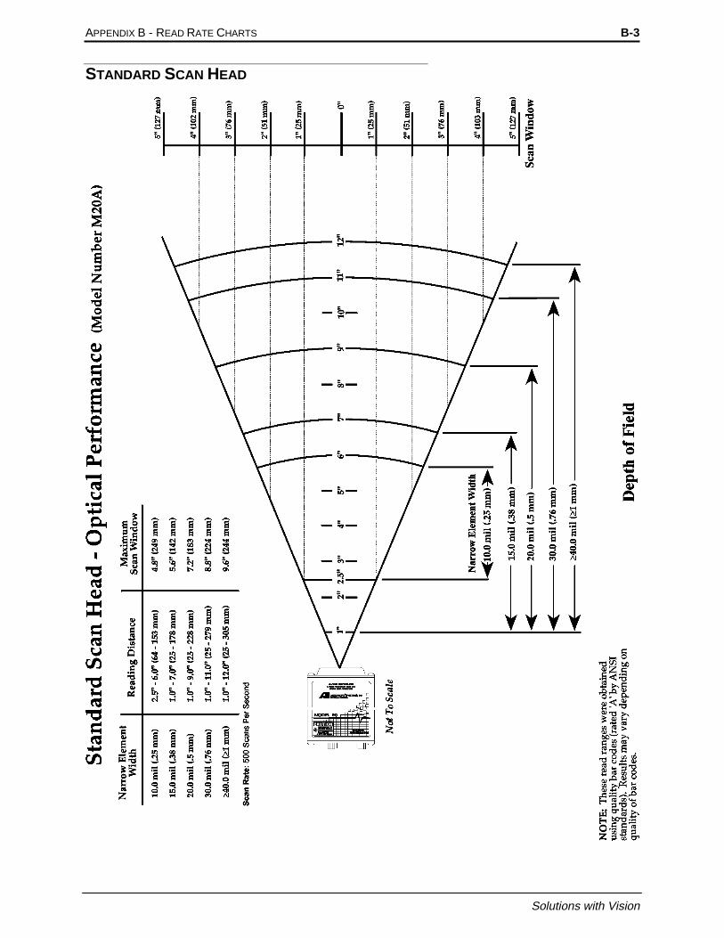
APPENDIX B - READ RATE CHARTS B-3
Solutions with Vision
STANDARD SCAN HEAD

B-4 MODEL 20 OPERATIONS AND MAINTENANCE MANUAL
Accu-Sort Systems
HIGH SPEED SCAN HEAD

APPENDIX B - READ RATE CHARTS B-5
Solutions with Vision
HIGH DENSITY SCAN HEAD

B-6 MODEL 20 OPERATIONS AND MAINTENANCE MANUAL
Accu-Sort Systems

Appendix C Contents
Appendix CPart Numbers
CHeading 2
PART NUMBERS........................................................................................C-3

C-2 MODEL 20 OPERATIONS AND MAINTENANCE MANUAL
Accu-Sort Systems

APPENDIX C - PART NUMBERS C-3
Solutions with Vision
PART NUMBERS
Listed below are the part numbers of some of the components and accessories ofthe Model 20.
Part Number Description1000017362 Small Scanner Interface without relays1000017365 Small Scanner Interface with relays1000014575 Interconnect Cable1000020527 Photoeye1000022163 110V AC Power Supply1000015618 220V AC Power Supply1000017359 110V AC Power Supply1000017360 220V AC Power Supply1000017384 Mounting Clips1000017383 Ladder Mounting Bracket1000017382 Picket Fence Mounting Bracket1000017379 Mounting Plate1000017380 Cradle Mounting Bracket1000017381 110V AC Model 20 Programming Kit1000017382 220V AC Model 20 Programming Kit1000017344 Model 20 Custom Assembly1000017345 Model 20 Custom 1 @ 10 Raster Assembly1000017346 Model 20 Custom .5 @ 10 Raster Assembly1000025478 Model 20, Standard, Linear Decoding, 12 Sided Mirror1000025479 Model 20, Standard, DRX Decoding, 12 Sided Mirror1000025480 Model 20, Standard, Linear Decoding, .5@10 Raster1000025481 Model 20, High Density, Linear Decoding, 12 Sided Wheel1000025482 Model 20, High Density, DRX Decoding, 12 Sided Wheel1000025483 Model 20, High Density, Linear Decoding, .5@10 Raster1000025484 Model 20, High Speed, Linear Decoding, 12 Sided Wheel1000025485 Model 20, High Speed, DRX Decoding, 12 Sided Wheel1000025486 Model 20, High Speed, Linear Decoding, .5@10 Raster
OTSDistributor
Units
For ordering information please refer to the Customer Service page at the front ofthe manual.

C-4 MODEL 20 OPERATIONS AND MAINTENANCE MANUAL
Accu-Sort Systems

Solutions with Vision
Glossary
GlossaryACKA control character sent to acknowledge that a transmission block has been received.
Active/Passive DeviceIn 20mA current loop communications, a device capable of providing the current for the loop (active) and a device that draws thecurrent from the equipment it is connected to (passive).
AddressA unique designation for the location of data or the identity of a smart device; allows each device on a single communicationsline to respond to its own message.
AEL (Accessible Emission Limit)The average power limitations of electronic radiation from a laser light source as defined by the CDRH.
AIMAutomatic Identification Manufacturers, Inc.
AlignmentThe position of a scanner or light source in relation to the target of a receiving element.
AlphanumericConsisting of letters, numbers, and symbols.
Ambient LightThe lighting conditions in the scanning area. Ambient light can interfere with successful scanning of bar codes.
ANSI (American National Standards Institute)The principle standards development group in the U.S. A non-profit, non-governmental group supported by over 1000 tradeorganizations, professional societies, and companies. Member body to the ISO (International Standards Organization).
ApertureTerm used on the required CDRH warning labels to describe the laser exit window.
ApplicationA use to which something is put, or how it is used.
APM ProtocolAcronym for Application Protocol Messages. A protocol used by system integrators who want to design systemapplications without AdaptaScan Software.
ASCII (American Standard Code for Information Interchange)Pronounced as-kee. A standard seven bit plus parity code, representing 256 characters, established by ANSI to achievecompatibility between data services.
Aspect RatioThe ratio of height to width of a bar code symbol. A code twice as high as wide would have an aspect ratio of 2; a code twice aswide as high would have an aspect ratio of ½ or 0.5.
Asynchronous TransmissionTransmission in which the time intervals between transmitted characters may be of unequal length. Transmission is controlled bystart and stop bits at the beginning and end of each character.
AutodiscriminationThe ability of bar code reading equipment to recognize and correctly decode more than one bar code symbology.
AutodistinguishThe ability of a scanner to recognize a selectable number of different symbologies and process the data without operatorintervention; this is a prerequisite feature of linear bar code scanners employed in open systems.
AutoloadThe process of automatically transferring scanned character strings and the symbology type into a match entry value.

2
Accu-Sort Systems
BarThe dark elements of a printed bar code symbol.
Bar CodeAn array of rectangular bars and spaces arranged in a predefined pattern to represent elements of data referred to as characters.
Bar Code CharacterA single group of bars and spaces that represent an individual number, letter, or other symbol.
Bar Code DensityThe number of characters that can be represented in a linear unit of measure. Bar code density is often referred to in charactersper inch (CPI).
Bar Code LabelA label that carries a bar code and can be affixed to an article.
Bar Code ReaderA device that examines a printed spacial pattern and decodes the encoded data.
Bar code symbolA group of bars that represent a character or group of characters whose width and spacing is determined by a set ofrules. In most cases, human readable characters are printed below the bars.
Bar HeightThe height of the shortest bar in a bar code.
Bar LengthThe bar dimension perpendicular to the bar width.
Bar WidthThe thickness of a bar measured from the edge closest to the symbol start character to the trailing edge of the same bar.
Baud RateA unit used to measure communications speed or data transfer rate; represents the number of discrete conditions or events persecond.
BCC (Block Check Character)Used to check transmission accuracy, a character transmitted by the sender after each message block and compared with a blockcheck character computed by the receiver.
Bed WidthThe width of the conveyor bed measured in inches.
BELA control character that is used when there is a need to call for attention; it may control alarm or attention devices.
Belt WidthThe width of the conveyor belt measured in inches.
BidirectionalA bar code symbol capable of being read successfully independent of scanning direction.
Bit (Binary Digit)The contraction of binary digit, the smallest unit of information in the binary system; a one or zero condition.
Bottom ReadWhen the scanner is mounted under the conveyor to read codes on the bottom of the boxes or on the front or back of the boxes. Ifused there is not enough clearance for a standard front or back read.
BPS (Bits per Second)Unit of data transmission rate. See baud rate.
BridgeAn interface between links in a communication network that routes messages from one link to another when astation on one link addresses a message to a station on another link.

GLOSSARY 3
Solutions with Vision
BufferA temporary storage device used to compensate for a difference in data rate and data flow between two devices (typically M).
BusAn internal pathway along which electronic signals travel between the components of an electronic device.
ByteA binary element string functioning as a unit, usually shorter than a computer “word”. Eight-bit bytes are most common. Alsocalled a “character”.
CART(Also known as trigger) A signal, typically provided by a photoeye or proximity switch, that informs the scan head of thepresence of an object within its reading zone.
CCD (Charge Coupled Device)Used in scanners to sense the light and dark areas of a symbol.
CDRH (Center for Devices and Radiological Health)This organization (a service of the Food and Drug Administration) is responsible for the safety regulations governing acceptablelimitations on electronic radiation from laser devices. Accu-Sort is in compliance with the CDRH regulations.
Capture countThe number of consecutive identical valid decodes that result in a valid read.
CharacterA single group of bars and spaces in a code that represent an individual number, letter, punctuation mark or other graphicelement. Used as part of the organization, control, or representation of data.
Character self-checkingThe feature which allows a bar code reader to determine if a scanned group of elements is a valid symbol character.If a symbology is described as character self-checking, a single printed defect (edge error) in any symbol characterdoes not produce a valid character.
Character setThose characters available for encodation in a particular automatic identification technology.
Check CharacterA character (usually at the end of the code) that is used to perform a mathematical check to ensure the accuracy of a scan of thebar code.
Code LengthThe length of the bar code measured from the start of the first bar to the end of last bar.
Code OrientationThe relationship of the bar code with reference to the scan head’s reading zone. Typical code orientations are Ladder and PicketFence.
Code PlacementVariation in code placement affects the ability of a scanner to read a code. The terms Tilt, Pitch, and Skew deal with the angularvariations of code placement in the X, Y and Z axes. Variations in code placement affect the pulse width and therefore thedecoding of the code. Pulse width is defined as a change from the leading edge of a bar or space to the trailing edge of a bar orspace over time. Pulse width is also referred to as a transition. Tilt, pitch, and skew impact the pulse width of the code.
Changes to this code presentation cause the bar codes to appear smaller to the scanner which results in a smaller pulse width.Each of these variation has a different effect on a scanner reading these codes and the combination of the variations leads to morecomplicated effects.
Code QualityThe number of scans successfully decoded during a read cycle.

4
Accu-Sort Systems
Code setThe specific assignment of data characters to symbol characters.
Communications ProtocolThe rules governing exchange of information between devices connected together on the same communications line.
ConfigurationThe arrangement and interconnection of hardware components within a system, and the hardware (switch andjumper) and software selections that determine the operating characteristics of the system.
Configuration fileThe set of attributes which belongs to and defines the operation of a single physical device.
Continuous codeA bar code symbology where all spaces within the symbol are parts of the characters (Interleaved 2 of 5). There isno interactive gap in a continuous bar code symbology.
Conveyor SpeedThe speed that the conveyor is moving measured in feet per minute. Conveyor speed directly impacts the time that the code is infront of the scanner; therefore, it affects the number of reads that are possible.
CPICharacters per inch. See density.
CR (Carriage Return)An ASCII or EBCDIC control character that moves the cursor or print mechanism to the left margin.
CRT (Cathode-Ray Tube)Device similar to a television screen for sending, receiving, and displaying serial data. Also known as Dumb Terminal, Displayscreen, or Monitor.
CTS (Clear to Send)The Modem interface signal that indicates to the DTE device to begin transmission.
Current LoopMethod of interconnecting terminals and transmitting signals, whereby a mark (binary 1) is represented by current on the line anda space (binary 0) is represented by the absence of current.
DecodeThe process of translating a bar code into data characters using a specific set of rules for each symbology.
DecoderAs part of a bar code reading system, the electronic package which receives the signals from the scanner, performsthe algorithm to interpret the signals into meaningful data and provides the interface to other devices.
Decoder LogicThe electronic package that receives signals from the scan head, interprets the signals into useful data, and provides the interfaceto other devices.
Depth of FieldThe distance between the maximum and minimum plane in which a symbol can be read. This range is from the specified opticalthrow to the far reading distance.
DensityThe number of data characters which can be represented in a linear unit of measure. Bar code density is oftenexpressed in characters per inch (CPI).
DIP SwitchesSwitches that are the approximate size of an integrated circuit.
Discrete codeA bar code or symbol where the space between characters, intercharacter gap, are not part of the code as with Code 39. Seecontinuous code.

GLOSSARY 5
Solutions with Vision
Dot Matrix PrinterA dot matrix printer is an impact printer that consists of a series of pins arranged in an array. The pins strike an inked ribbonagainst the label stock to form the bar code and characters. This is the most common type of printer used to print labels on-demand. Some dot matrix printers use a moving print head and stationary stock. The print head moves across the label, printingone dot at a time, to complete one line. The print head then begins printing the next line. Other dot matrix printers use astationary print head. These printers typically print one line at a time and are therefore much quicker than a printer with a movingprint head.
Common Problems with dot matrix printingThe printed ink (bars) tends to expand or “bleed”. This causes the size of the bars of a code to expand while shrinking the spaces.There tends to be small gaps between pins of a dot matrix printed bar. This can lead to problems with scanners because thesegaps can appear as spaces. Ribbon wear is a factor when printing dot matrix codes. If a printer uses a circular type ribbon (ribbonis used over and over again) the contrast of the bar code diminishes over time. A bar code printed with an old ribbon can be moredifficult to read than one printed with a new ribbon.
Benefits of dot matrix printingIt is inexpensive to print bar codes using dot matrix printers.
DownloadingThe process of sending configuration parameters, operating software or related data from a central source to remote stations.
DSR (Data Set Ready)An RS232 modem interface control signal which indicates that the terminal is ready for transmission.
DSR (Data Terminal Ready)Modem interface signal which alerts the modem that the DTE device is ready for transmission.
Duplex TransmissionSee Full and Half Duplex.
EANEuropean Article Number System. The international standard bar code for retail food packages.
EDI (Electronic Data Interchange)A method by which data is electronically transmitted from one point to another.
EIA-232Interface between data terminal equipment and data communication equipment employing serial binary data interchange.
EIA-422Electrical characteristics of balanced-voltage digital interface circuits.
EIA-485The recommended standard of the Electronic Industry Association that specifies the electrical characters of generators andreceivers for use in balanced digital multipoint systems.
ElementDimensionally the narrowest width in a character - bar or space.
Element widthThe thickness of an element measured from the edge closest to the symbol start character to the trailing edge of thesame element.
Encoded areaThe total linear dimension consisting of all the characters of a code pattern, including start and stop characters anddata.
ENQ (Enquiry)A transmission control character used as a request for a response from a remote station. (^E)
ESC (Escape)A control character which is used to provide additional control functions. It alters the meaning of a limited number ofcontinuously following bit combinations. (^[)
Error

6
Accu-Sort Systems
A discrepancy between a computed, observed or measured value or condition and the true, specified or theoreticallycorrect value or condition.
ETX (End of Text)A transmission control character that terminates a text.
Even ParityA data verification method in which each character must have an even number of on bits.
Expansion BusAllows the microprocessor to communicate with controllers for peripheral devices, such as a network card or an internal modem.
Far DistanceThe distance (in inches) from the face of the scanner to the farthest point at which a code can be successfully scanned.
Flying LeadA lead that exits the back of the connector hood on the outside of the cable jacket. It is normally attached to the drain wire orshield and connected to the chassis of the switch, modem, etc. It can also be a hardware control lead.
Front ReadThe scanner is mounted to read bar codes on the leading edge of a box as it passes the scanner. In a front read application, thescanner can be mounted above or on the side of the conveyor.
Full Duplex (FDX)Simultaneous, two-way, independent transmission in both directions.
Guard bars1) The bars at the ends and center of a UPC and EAN symbol that ensure a complete scan of the bar code. 2) Theoptional bars outside the quiet zone of an Interleaved 2 of 5 symbol that ensure a complete scan of the bar code.
Half Duplex (HDX)Transmission in either direction, but not simultaneous.
HandshakingExchange of predetermined signals between two devices establishing a connection. Usually part of a communications protocol.
Height of ScanThe maximum vertical scanning dimension of a moving beam scanner at a specific distance from the face of the scanner.
Helium Neon LaserA type of laser commonly used in bar code scanning. Because the laser beam is bright red, bars must not be printed with red inksince they would be indistinguishable from the code’s background.
HexadecimalA base-16 numbering system that uses the symbols 0,1,2,3,4,5,6,7,8,9,A,B,C,D,E,F.
Host1) A central controlling computer in a network system. 2) Any device on a network system that provides acontrolling function to another device on the network. 3) Any intelligent device for which another device isproviding a communication interface to a network.
Ink Jet PrintingInk jet is a non-contact printer that projects drops of ink at a printing surface. The sprayed drops are controlled electronically toform a bar code.
Common Problems with ink jet printingIts main restriction is that ink jet printing is usually capable of printing only low density codes.
Benefits of ink jet printingBecause ink-jet printers are non-contact and non-impact, they can print bar codes on a variety of contoured, rough, and delicatesurfaces. Capable of printing random or sequential information on labels. Ink jet printers can print directly on cartons and avoidthe cost of label stock.
Input/Output Modules

GLOSSARY 7
Solutions with Vision
Since many scanners are operating in environments that have electrical noise problems, it is helpful to have equipmentelectrically isolated from other equipment. The standard method for isolating inputs and outputs is through the use ofOPTICALLY ISOLATED INPUT/OUTPUT MODULES. These flexible modules allow the scanner to control high voltageoutputs that are susceptible to noise. Since they are isolated from each other the noise is not picked up in the scanner.
The modules come in both input and output versions. The output versions are controlled by a 5VDC input. The output of themodules can range from 24VAC - 140VAC or 3VDC - 200VDC. Foreign voltage ranges are available. The maximum currentthat the modules can supply is limited by the output voltage and the module type. The input versions are controlled by either aDC or AC input ranging from 3VDC - 32VDC or 90VAC - 140VAC. Foreign voltage ranges are available. The output of themodules is a 5VDC level. The maximum current is limited by the input modules. These output modules are commonly used tocontrol diverters, alarms, external relays, etc. The input modules can be used for photoeye inputs.
Intercharacter GapThe space between two adjacent bar code characters in a discrete code.
InterfaceA shared boundary defined by common physical interconnection characteristics, signal characteristics and meanings ofinterchanged signals.
Interleaved Bar CodeA bar code in which characters are paired together using bars to represent the first character and spaces to represent the second.
Inter-symbol no-read countThe minimum number of no-reads that must occur between symbols scanned when Self-Triggered (continuous decode) isselected as the decode trigger. Symbols that are not preceeded by the minimum nuber of no-reads are ignored.
I/OThe abbreviation for input/output. The keyboard and a printer, are examples of I/O devices. I/O activity is different fromcomputational activity. When a program sends a document to the printer, it is engaging in I/O activity; when the program sorts alist of terms, it is engaging in computational activity.
JumperA wire that connects a number of pins on one end of a cable only, such as looping back Request to Send from Clear to Send pins4 and 5.
Ladder OrientationWhen the bar code’s bars are positioned horizontally on the product, causing them to appear as a ladder. The ends of all bars willenter the scan window first.
LANThe acronym for local area network. A LAN system is usually confined to the same building or a few nearby buildings, with allequipment linked by wiring dedicated specifically to the LAN.
Laser GunA hand-held non-contact laser scanner that is usually activated with a trigger.
Laser ScannerAn optical bar code reading device using a low energy laser light beam as its source of illumination.
Laser PrintingLaser printers use a pulsed or rastered laser light source to positively charge an image on a dielectric cylinder of an electrostaticprinting mechanism. Toner used in the laser printing process adheres to the charged portion of the cylinder. This toner is thentransferred to paper using heat.
Common Problems with laser printing

8
Accu-Sort Systems
The labels are more expensive than those used in dot matrix printers.
Benefits of laser printingLabels can be printed at various speeds. Laser printed bar code labels are high quality and very accurate.
LCD (Liquid Crystal Display)A low-power display often used for notebook computers. An LCD consists of a liquid crystal solution between two sheets ofpolarizing material. An electric current causes each crystal to act like a shutter that can open to allow light past or close to blockthe light.
LED (Light Emitting Diode)A semiconductor generally made from gallium arsenide, that can serve as a visible or near infrared light source when voltage isapplied continuously or in pulses. LEDs have extremely long lifetimes when properly operated.
LF (Line Feed)An ASCII control character that moves the cursor or print mechanism to the next line. (^J)
mAThe abbreviation for milliampere(s).
MatchA condition in which decoded data matches data in the match entry.
Match entryAn output condition in which decoded data matches and the data in a match entry configuration.
MemoryA computer can contain several different forms of memory, such as RAM, ROM, and video memory. The term memory isgenerally used to define RAM. When a computer has 8 MB of memory, it actually has 8 MB of RAM.
Memory AddressA specific location, usually expressed as a hexadecimal number, in the computer’s RAM.
Message1) A meaningful combination of alphanumeric characters that establishes the content and format of a report. 2) In acommunication network, the unit of exchange at the application layer.
Message bufferStorage register for the temporary storage of data that allows decoding to continue while the host is retrieving datafrom the serial port.
Message buffer warningAn output condition that occurs when the message buffer has used a defined amount of the message buffer.
MHzThe abbreviation for megahertz.
MicroprocessorThe primary computational chip inside the computer, referred to as the “brain”. The microprocessor contains an arithmeticprocessing unit and a control unit. Software written for one microprocessor must usually be revised to run on anothermicroprocessor.
MilOne thousandth of an inch (0.001 inch). Bars and spaces of codes are commonly referred to as being a certain number of milswide.
MisreadThe scanner incorrectly decodes a bar code as it passes through the scan zone.
Modulo check digit or characterA calculated character within a data field used for error detection. The calculated character is determined by amodulus calculation on the sum or the weighted sum of the data field contents.
Mouse

GLOSSARY 9
Solutions with Vision
A pointing device that controls the movement of the cursor on a screen. Mouse-aware software allows the user to activatecommands by clicking a mouse button while pointing at objects displayed on the screen.
Moving-BeamRather than using a stationary laser beam and relying on product movement for a single scan, a multi-facet mirror wheel andmotor is used to ‘move’ the beam across the code several times while in motion itself.
Moving-Beam Bar Code ScannerA device that dynamically searches for a bar code symbol by sweeping a moving optical beam through a field of view called thescanning zone. Automatic bar code reader that reads codes by sweeping a moving optical beam through a field of view. Moving-beam scanners are usually mounted in a fixed position and read codes as they pass by.
MTBFThe abbreviation for mean time between failures.
Multidrop LineA single communications circuit that interconnects many stations, each of which contains terminal devices. See EIA-485.
NAK (Negative Acknowledgment)A control character used to indicate that the previous transmission block was in error and the receiver is ready to acceptretransmissions.
Narrow Bar (NB)/Narrow Space (NS)Smallest code element, bar or space, in the bar code symbol. Also known as the X dimension.
NCDRH (National Center for Devices and Radiological Health)This organization (a service of the Food and Drug Administration) is responsible for the safety regulations governing acceptablelimitations on electronic radiation from laser devices. Accu-Sort is in compliance with the NCDRH regulations.
Near DistanceThe distance (in inches) from the face of the scanner to the closest point at which a code can be successfully scanned.
NEMAIn order to rate the quality of an enclosure the National Electrical Manufacturers Association (NEMA) has developed a systemfor rating all enclosures. A partial list of the NEMA enclosures is shown below along with what particles it is designed to restrict.
Ratings3 Enclosures are intended for indoor or outdoor use primarily to provide protection against windblown dust, rain, and sleet,
and is undamaged by the formation of ice on the enclosure.4 Enclosures are intended for indoor or outdoor use primarily to provide protection against windblown dust and rain, splashing
water, and hose-directed water; undamaged by the formation of ice on the enclosure.4X Enclosures are intended for indoor or outdoor use primarily to provide protection against corrosion windblown dust and rain,
splashing water, and hose directed water; undamaged by the formation of ice on the enclosure.6 Enclosures are intended for use indoors or outdoors where occasional submersion is encountered.12 Enclosures are intended for indoor use primarily to provide a degree of protection against dust, falling dirt, and dripping
non-corrosive liquids.13 Enclosures are intended for indoor use primarily to provide a degree of protection against dust, spraying of water, oil, non-
corrosive coolant.
NetworkA series of stations (nodes) connected by some type of communication medium. A network may be made up of asingle link or multiple links.
NVCThe acronym for non-valid code. Defines the condition that occurs when an object has been scanned and no bar code could bedecoded. Usually, this indicates that either no code was on the object or the code was badly damaged and could not be decoded.
NodeThe connection point at which media access is provided.
No-matchAn output condition in which decoded data does not match an entry in the match code table.
No-ReadWhen the scanner is unable to decode a bar code as it passes through the scan zone.

10
Accu-Sort Systems
Non-ReadThe absence of data at the scanner output after an attempted scan due to no code, defective code, scanner failure or operator error.
Odd ParityA data verification method in which each character must have an odd number of on bits.
OmnidirectionalOrientation is unpredictable and can be ladder, picket fence, or any angle in between. A single scan line is not sufficient to scanbar codes oriented omnidirectionally.
Operating RangeThe sum of the scanner’s optical throw and depth-of-field.
Optical ThrowMeasured distance from the scanner’s window to the near reading distance of the depth of field. Typically, this is the closest a barcode can be to the scanner’s window and still be properly decoded.
Optimum Reading DistanceTypically, the center of the depth of field.
OCROptical Character Recognition.
OrientationThe alignment of the code’s bars and spaces to the scan head. Often referred to as vertical (picket fence) and horizontal (ladder).
Output counterA counter that is associated with each output condition. The counter increments by 1 each time the conditionoccurs.
OversquareUsed to describe bar codes that are taller (from top to bottom of the bars) than they are wide (from first to last bar).
Trigger or CartThe standard abbreviation for a signal indicating that an object is passing by the scanner is called Cart. This signal indicates tothe scanner to start or stop reading.
Trigger or Cart CycleThe time during which the scanner is attempting to read the bar code.
Hardware CartThis is an electrical signal from a relay, photoeye, or proximity switch indicating that an object is passing by the scanner.
Start and End of Cart PhotoeyesThe cart cycle begins when the start of cart photoeye is blocked and continues until the end of cart photoeye is unblocked. Relaydecisions and data communication take place after the end of cart photoeye is unbroken. The diagram below shows start and endof cart photoeye placement.
Induct PhotoeyesThe cart cycle begins when the start of cart photoeye is blocked and continues until the cart photoeye is unblocked. Blocking theINDUCT photoeye causes relay decisions and data communication. For this placement the distance between the CART andINDUCT photoeyes must be less than the minimum box size plus the minimum box spacing.
Software CartA serial message from an external device that controls the cart cycle.
Self CartThis form of cart requires no input signal. The scanner is continuously attempting to decode bar codes. When a scanner is in selfcart, there is no way of determining if there is a package present or a NO-READ.
Flip LensA moveable lens inside a scanner that increases Depth of Field.
Package SpacingThis is the spacing between items on a conveyor. Package spacing is measured one of two ways: Leading edge of one box toleading edge of the next or trailing edge of one box to trailing edge of the next. Package spacing is critical to system operations.
Parameter

GLOSSARY 11
Solutions with Vision
A value or opinion that you specify to a program. A parameter is sometimes called a switch or an argument.
Parity BitA bit that is set at “0” or “1” in a character to ensure that the total number of 1 bits in the data field is even or odd.
Percent good readsThe number of successful reads per refresh period. This is valid only when the refresh period is set to 0.
Performance indicatorA bar code decoder function that counts the number of decodes during a trigger period. When the period = 0, theperformance indicator provides the number of decodes (up to 100 attempts). Use the performance indicator toprovide a general indication of bar code symbol quality or verify proper setup of the scanner.
Performance indicator limitA set point that will produce a discrete output if the performance indicator falls below the set point value.
Pen ScannerA pen-like device either connected by wire to a device, or self-contained, used to read bar codes. Requires direct contact with thesymbol.
Peripheral DeviceAn internal or external device, such as a printer, a disk drive, or a keyboard, connected to a computer.
PhotoeyeUsed as a presence detector to identify objects in the scanner’s reading zone. The photoeye emits a beam and is used with areflector to create a photoelectric circuit. When the beam is blocked by an object, breaking the circuit, a signal called CART issent to the scanner.
Picket Fence OrientationWhen the bar code’s bars are positioned vertically on the product, causing them to appear as a picket fence. The first bar willenter the scan window first.
PitchRotation of a code pattern about the X-axis. The normal distance between center line or adjacent characters.
Polarized LaserA specialized laser source used in high glare environments.
PollingA means of controlling devices on a multipoint line.
ProtocolA formal set of conventions governing the formatting and relative timing of message exchange between two communicatingsystems.
Pulse WidthA change from the leading edge of a bar or space to the trailing edge of a bar or space over time. Pulse width is also referred to asa transition.
QueueA buffer used to hold data in order until it is used or transmitted.
Quiet ZoneRequired distance before the first bar and after the last bar of the code that must be free of marks or printing.
Radio FrequencyNon-optical automatic identification devices that use radio waves to transmit data.

12
Accu-Sort Systems
RasterThe process of projecting the laser beam at varied angles spaced evenly from each other. Typically, the mirror wheel surfaces areangled to create multiple scan lines instead of a single beam.
Raster Mirror WheelThe standard mirror wheel forms the laser line that is projected from the scanner. Although the mirror wheel projects 8 separatelines (for an 8-sided mirror wheel), the speed of the sweep makes it appear that it is actually one line. This type of mirror wheel isadequate for a ladder orientation because the laser line will pass from the bottom to the top of the code. For a picket fenceorientation the standard mirror wheel is not always adequate. One problem facing the picket fence orientation is that the sameportion of the code is being repeatedly scanned. If the printing quality at this point is not good the label may not be scanned eventhough other parts of the label are good. Another problem for a picket fence orientation is the placement of the label. If theplacement is off enough a single scan line will not read all the bar codes presented to the scanner.
Read-onlyA read-only file is one that you are prohibited from editing or deleting. A file can have read-only status if:
• Its read-only attribute is enabled.• It resides on a physically write-protected diskette.• It is located on a network in a directory to which the system administrator has assigned read-only rights to you.
Read ZoneArea in front of the scanner’s window in which the bar code should appear for scanning. This zone consists of the scan windowand the raster width (if used).
ReflectanceThe amount of light returned from an illuminated surface.
RelayRelays are simply electrical switches that are typically used to control external diverts, alarms, etc. Relay types available areFORM A and FORM C. FORM C type relays have both normally open and normally closed contacts available while FORM Atype relays have only normally open contacts available.
Relay Output DurationThis is the time (in seconds) after the relay is energized that it should be turned off.
Relay Output DelayThe time lapse between an event and the energizing of the relay.
Request To Send (RTS)An RS232 modem interface signal which indicates that the DTE has data to transmit.
ResolutionThe narrowest element dimension which can be distinguished by a particular reading device or printed with a particular device ormethod.
Response TimeThe elapsed time between the generation of the last character of a message at a terminal and the receipt of the first character ofthe reply. It includes terminal delay and network delay.
ROMThe acronym for read-only memory. The computer contains programs essential to its operation in ROM. A ROM chip retains itscontents even after you turn off your computer.
RPMThe abbreviation for revolutions per minute.
RS-232Interface between data terminal equipment and data communication equipment employing serial binary data interchange.
RS422The Electronic Industries Association standard that specifies the electrical characteristics of balanced voltage digital interfacecircuits.
RS485The Electronic Industries Association standard that specifies the electrical characters of generators and receivers for use inbalanced digital multipoint systems.
Scan

GLOSSARY 13
Solutions with Vision
A single pass of the laser beam over the code or a portion of the code. The search for a bar code symbol that is to be opticallyrecognized.
Scan AreaThe area intended to contain a symbol.
Scan WindowThe usable length of the scanning beam that may detect the bar codes. The scan window is perpendicular to the depth of field.
ScannerAn electronic device that optically converts printed information into electrical signals. These signals are sent to the decoder logic.
Scanner OrientationRelationship of the scan head with reference to the bar code’s location on products. The scan head must be set up to insure thatall code bars and spaces are bisected at the same time. Typically, either side read or top read is used for picket fence or laddercode orientations.
SCSIThe acronym for small computer system interface. An I/O but interface with faster data transmission rates than standard ports.The user can connect up to seven devices to one SCSI interface.
Self-checkingA bar code or symbol using a checking algorithm which can be independently applied to each character to guard againstundetected errors.
SensorA device that detects or measures something and generates a corresponding electrical signal to an input circuit of acontroller.
Serial PortAn I/O port used most often to connect a modem or a mouse to your computer, identifiable by its 9-pin connector.
Serial TransmissionThe most common transmission mode; serial, information bits are sent sequentially on a single data channel.
Serial Asynchronous Transmission Of DataThe following are common communications interfaces: RS232, RS422, RS485, 20mA current loop and RS423.
When data is transmitted serially from a communications port, the information is transferred between the two devices one data bitat a time. The data flow can follow one of three different communications modes: simplex, half duplex, or full duplex. Eachcharacter of data within the data flow is transported in a binary bit frame called the asynchronous data frame.
The start bit begins each frame. A low voltage signal on the data communications line marks the beginning of the start bit, atwhich point the receiving device begins looking for binary zeros and ones (0’s and 1’s).The following five to eight data bits (thenumber depends on the format used) comprise the binary character. For error detection, an optional parity bit can define whetherthe total number of zeros or ones was even or odd. There are five different parity selections as shown below:
ODDlast data bit is a logical 0 if the total number of logical 1’s in the first seven data bits is odd.
EVENlast data bit is a logical 0 if the total number of logical 1’s in the first seven data bits is even.
MARKlast data bit is always a logical 1 (i.e.: high/mark).
SPACElast data bit is always a logical 0 (i.e.: low/space).
OFF (NONE)last data bit is not present.
The method used to catch errors by using parity bits is as follows: When the transmitter frames a character, it tallies the numberof 0’s and 1’s within the frame and attaches a parity bit. (The parity bit varies according to whether the total is even or odd.) Thereceiving end then counts the 0’s and 1’s and compares the total to the odd or even recorded by the parity bit. If a discrepancy isnoticed by the receiving end, it can flag the error and request a retransmission of the data.

14
Accu-Sort Systems
A stop bit is used to signal the end of the character. (Stop bits are typically one or two bits in length. The slower the transmissionspeed, the more stop bits required for recognition of the end of the data frame.)
In addition to the direction of data flow and the data framing, there are other considerations to insure uniform transmissions.Certain operating parameters must be followed to prevent the loss of valuable data.
The first consideration is the speed of transmission, known as baud rate. Serial data transmission is measured in bits per second(BPS). The baud rate selections typically available are: 110, 300, 1200, 2400, 4800, 9600 and 19200. To enable two devices tointeract, they must both be transmitting/receiving data at the same baud rate. If it is not possible to do this, there must be a buffer(typically additional storage memory) that accommodates the differences in communications speed.
Many serial communications links also use a flow control system to handle data transmission in addition to memory buffers.
X-ON/X-OFF ProtocolA common type of flow control is the X-ON/X-OFF protocol. When a receive buffer nears its memory capacity, the receivingdevice sends an ASCII X-OFF signal to the transmitting device, telling it to stop sending data. When the memory buffer hasenough space to handle more data, the X-ON signal is sent to the transmitting device, telling it to start sending data again.
ACK/NAK ProtocolAnother common protocol is ACK/NAK protocol. When the device transmits a message to the host, the host responds with eitheran ACK (06H) or a NAK (15H). If the host transmits an ACK to the device, the device deletes its transmit message and thecommunication sequence is complete. If the host transmits a NAK, the device will retransmit. The device resends data amaximum of three times. Optionally this may be changed to 1, 2, 3, or infinite retransmits by the user. If the device receives afourth NAK, it will delete the data in its transmit buffer and display “MAX REXMITS”.A transmitting device ignores ACK and NAK characters received during data transmission. If, for example, a device receives aNAK during a data transmission, it will not resend the data at the completion of the transmission.
The device also has a retransmit timer. This timer is activated each time the device transmits data to the host. If the timer runs fortwo seconds (this is also changeable) and the device does not receive an ACK or NAK from the host, a timeout occurs and thedevice retransmits its data. Each time the device retransmits because of a timeout, it treats the timeout the same as receiving aNAK from the host computer. If the device does not receive an ACK before the end of the fourth timeout, it will delete the datain its transmit buffer and display “MAX REXMITS”. The device deletes data in its transmit buffer and displays the error messagewhen any combination of four timeouts and NAKs from the host occurs.
When the device receives a message from the host, it calculates the BCC for the message and compares the calculated BCC to thereceived BCC. If the two values match, the device transmits an ACK, ending the communication. If the values do not match, thedevice transmits a NAK to the host and waits for the host to retransmit the message. The host, like the device, should retransmit amaximum of three times.
The sequence number starts at zero (30H) and is incremented each time a device transmits a new message. When the sequencenumber reaches nine (39H), it wraps around to one (31H). If the sequence number skips a number, the receiving device knowsthat a message was lost. If the same sequence number is received on two sequential messages, the second message is respondedto with an ACK or NAK (as appropriate) and ignored.
ShieldingProtective covering that eliminates electromagnetic and radio frequency interference.
Side ReadThe scanner is mounted to read the side of a box as it passes by the head.
SignalAn impulse or fluctuating electrical quantity (i.e.: a voltage or current) the variations of which represent changes in information.
SkewRotation about the Y-axis. Rotational deviation from correct horizontal and vertical orientation; may apply to single character,line or entire encoded item.
SpaceThe lighter elements of a bar code symbol formed by the background between bars.
Specular ReflectionsA condition when the laser light is reflected back from the code’s surface at an angle equal, or nearly equal, to the angle ofincidence of the laser light. This condition makes it difficult for the scan head to detect the differences in light variation causedby the code’s bars and spaces.

GLOSSARY 15
Solutions with Vision
SpotThe undesirable presence of an area of low reflectance in a space.start and stop characters
Stacked Codes16K and Code 49 are examples where a long symbol is broken into sections and "stacked" one upon another similar to sentencesin a paragraph. Extremely compact codes.
Start BitIn asynchronous transmission, the first bit or element in each character, normally a space, that prepares the receiving equipmentfor the reception and registration of the character.
Stop BitThe last bit in an asynchronous transmission, used to indicate the end of a character, normally a mark condition, that serves toreturn the line to its idle or rest state.
STX (Start of Text)A transmission control character that precedes a text and is used to terminate a heading. (^B)
SymbolA combination of characters including start/stop and checksum characters, as required, that form a complete scannable bar code.
SymbologiesCode 39A bar code with a full alphanumeric character set, a unique start and stop character, and three other characters. The name isderived from its code structure, which is 3 wide elements out of a total of 9 elements. The nine elements consist of five bars andfour spaces.
Code 128A bar code symbology capable of encoding the full ASCII 128 character set. It encodes these characters using fewer codeelements per character resulting in a more compact code. It features a unique start and stop character for bidirectional andvariable length decoding, both bar and space character parity for character integrity, a check character for symbol integrity, afunction character for symbol linking, and spare function characters for unique application definition and/or future expansion.
Interleaved 2 of 5 (I 2of5)A bar code with a numeric character set with different start and stop characters. The name is derived from the method used toencode two characters. In the symbol, two characters are paired together using bars to represent the first character and the spacesto represent the second. This interleaved structure allows information to be encoded in both the bars and the spaces. A startcharacter, bar and space arrangement, at one end, and a different stop character bar and space arrangement at the other end,provide for bidirectional decoding of this symbol.
SyntaxThe rules dictating how you must type a command or instruction so the computer will understand it.
System.ini fileWhen you start Windows, it consults the system.ini file to determine a variety of options for the Windows operating environment.Among other things, the system.ini file records which video, mouse, and keyboard drivers are installed for Windows. Runningthe Control Panel or Windows Setup program may change options in the system.ini file.
TagA collection of information associated with a single variable or I/O point.
Two-width symbologyA bar code symbology whose bar and spaces are characterized simply as wide or narrow. Codabar, Code 39, andInterleaved 2 of 5 are examples of two-width symbologies.
Terminal ProgramComputer software that sends, receives, and displays serial data.
Thermal PrintingThermal printers use heated print heads and special heat activated paper. There are two types of thermal printers. One uses amethod similar to the dot matrix printer where an array of heated dots move along the paper and form the character or bar code.

16
Accu-Sort Systems
The other method uses a heated bar and the paper moves across the bar. Another type of thermal printer is called a ThermalTransfer printer. The main difference between this type of printer and a thermal printer is the use of heat sensitive ribbons asopposed to heat sensitive paper. This type of printing is permanent on label stock.
Common Problems with thermal printingSince the paper used is heat activated the labels will deteriorate over time in a warm environment. Infrared scanners cannot detectthe bar codes and consequently a visible red light laser must be used to scan these codes.
Benefits of thermal printingThermal printers are quiet and inexpensive.
Thermal TransferA printing system like thermal except a one-time ribbon is used and common paper is used as a substrate. Eliminates theproblems of fading or changing color inherent in thermal printing.
TiltRotation around the Z axis. Used to describe the position of the bar code with respect to the laser scan line.
Trigger(Also known as cart) A signal, typically provided by a photoeye or proximity switch, that informs the scan head of the presenceof an object within its reading zone.
UCC (Uniform Code Council)The organization which administers the UPC and other retail standards.
UndersquareUsed to describe bar codes that are longer (from the first to last bar) than they are high (from the top to bottom of the bars).
UPCAcronym for Universal Product Code. The standard bar code type for retail food packaging in the United States.
V
UPSThe abbreviation for uninterruptible power supply. A battery-powered unit that automatically supplies power to your computer inthe event of an electrical failure.
UtilityA program used to manage system resources including memory, disk drives, and printers.
Vane RasterDecreases the amount of scans possible due to a smaller percentage of scans bisecting the code.
VerifierA device that makes measurements of the bars, spaces, quiet zones and optical characteristics of a symbol to determine if thesymbol meets the requirements of a specification or standard.
Vibrating VaneA variable raster that can have an unlimited number of raster lines. It covers a larger area and is adjustable.
Visible Laser DiodeA light source used in scanners to illuminate the bar code symbol. Generates visible red light at wavelengths between 660 and700 nM. Replaced Helium-Neon tubes in most scanners because they are small and consume less power.
VoidThe undesirable presence of an area of high reflectance in a bar.
W
Wand ScannerA hand-held contact laser scanner that an operator guides across the bar code.
WedgeA device that plugs in between a keyboard and a terminal. It allows data to be entered either by keyboard or by various types ofscanners.

GLOSSARY 17
Solutions with Vision
Wide Bar (WB)/Wide Space (WS)Widest code element, bar or space, in the bar code symbol.
Wide to Narrow RatioDividing the size of the wide elements by the size of the narrow elements of a bar code yields the bar and space ratios. Bar andspace ratios can differ. NOTE: If the narrow bar and narrow space are equal and the wide bar and wide space are equal then youcalculate only one ratio.
WindowA display area that the users interacts with to operate a tool.
WordA unit of data which contains two bytes (16 bits).
Write-protectedRead-only files are said to be write-protected. You can write-protect a 3.5-inch diskette by sliding its write-protect tab to the openposition and a 5.25-inch diskette by placing an adhesive label over its write-protect notch.
"X" DimensionThe dimension of the narrowest bar and narrowest space in a bar code.
XONA control character sent by the receiving device to signal the transmitting device to begin sending data.
XOFFA control character sent by the receiving device to signal the transmitting device to stop sending data.

18
Accu-Sort Systems

Index
AAutodiscrimination..........................................................1-3Automatic Laser Control .................................................1-3
BBar Code Types ...............................................................1-4
CChecking the Packing Slip...............................................1-8Clips ................................................................................2-3code densities ..................................................................1-3Communications..............................................................1-4Cradle Mounting Bracket
Mounting.....................................................................2-7
DDamaged Equipment .......................................................1-8decoder/logic ...................................................................1-3Decoding Bar Codes........................................................1-5DRX technology..............................................................1-3
EEnclosure.........................................................................1-4external decoder/logic unit ..............................................1-3
HHigh Density scanning ....................................................1-3
IIdle indication..................................................................1-6
LLadder Mounting
Mounting.....................................................................2-5LED.................................................................................1-6LED Functionality...........................................................1-7LEDs ...............................................................................1-3
MMissing Equipment..........................................................1-8Mounting Plate ................................................................2-4
NNo-read indication .......................................................... 1-6
PParts
Mounting Hardware.................................................... 1-9Photoeye ..................................................................... 1-9Power Supply.............................................................. 1-9Programming Kit ........................................................ 1-9
Parts Table ...................................................................... 1-9Photoeye
Mounting .................................................................... 2-8Picket Fence Mounting
Mounting .................................................................... 2-6Power .............................................................................. 1-4Power Requirements ....................................................... 1-4Packing slip..................................................................... 1-8Product Specifications .................................................... 1-4
RRadiant Power Output..................................................... 1-4RISC Processor ........................................................1-3, 1-5
SScan Rate ........................................................................ 1-4Scanning Range .............................................................. 1-4Size ................................................................................. 1-4
TTemperature Range......................................................... 1-4Trigger Indication ........................................................... 1-6
VVisual Diagnostics .......................................................... 1-4
WWeight............................................................................. 1-4
Index

2 MODEL 20 OPERATIONS AND MAINTENANCE MANUAL

Revision History
Document RevisionNumber
ECNNumber Date Changes Made
2.0 6010 11/5/00 rev 2.0 release for Small Scanner CD-ROM (p/n 1000025606)2.1 5731 01/23/01 new part numbers added for OTS distributor units
Revision History

Accu-Sort Systems