access management for private developments
TRANSCRIPT

Approved:ennis Hunter, Deputy Director
County of Los AngelesDepartment of Public Works
Access Management ForPrivate Developments
Guidelines Manual
May 2011

Rec
ord
of R
evis
ions
NO
.D
ES
CR
IPTI
ON
OF
RE
VIS
ION
RE
VIS
ION
EFF
EC
TIV
E D
ATE
:
1
Revis
ed o
rigin
ally
appro
ved M
ay 2
011 "
Left
-Turn
Lane I
mple
menta
tion F
or
Private
Develo
pm
ent
Fronting T
wo-L
ane,
Rura
l U
ndiv
ided H
ighw
ays
Guid
elin
es
Manual"
to
reflect
a c
hapte
r la
yout
that
would
be m
ore
conduci
ve t
o a
ddin
g a
dditio
nal guid
elin
em
ate
rial (i
n t
he
form
of
addtional ch
apte
rs)
at
a late
r date
_ T
he
Manual title
has
changed t
o "
Acc
ess
Managem
ent
For
Private
Develo
pm
ent"
and t
he o
rigin
al Le
ft-
Turn
Manual has
now
beco
me C
hapte
r 1.
Added C
hapte
r 2,
"Rig
ht-
Turn
Lane
I mple
menta
tion F
or
Private
Develo
pm
ent
Fronting T
wo-L
ane,
Rura
l, U
ndiv
ided
Hig
hw
ays
June
2011
Rev
ised
Jun
e 20
11
Table of Contents
1) INTRODUCTION ............................................................................... 2
2) ACKNOWLEDGEMENTS .................................................................. 3Document Preparation Team
Chapter Listing
Chapter 1 — Left-Turn Lane Implementation for Private DevelopmentFronting Two-Lane Rural Undivided Highways ..................... ........ 1-1
Chapter 2 — Right-Turn Lane Implementation for Private DevelopmentFronting Two-Lane Rural Undivided Highways .............................. 2-1
Revised: June 2011

Section 1 Introduction
Increased development within Los Angeles County has resulted in a rise in thedemand for direct access connections from developed lots to the County highwaynetwork. It is these access points, if not designed, managed, and locatedappropriately, that could contribute to traffic delays and conflicts among thevarious users of a roadway.
The content within this manual shall serve as a standardized approach for thedesign of access points for development within Los Angeles County and shall beused as a guideline to aide private developers, their engineers, and consultantsin designing a project access point that not only will benefit the County's highwaysystem but also the project itself. Public Works staff will also use this guidelinemanual to assist in the formulation and preparation of conditions of approval fortentative maps, parcel maps, and plot plans (associated with conditional usepermits, and other single-lot developments, subject to conditions).
These guidelines shall be applicable for all private developments, subject todiscretionary approval or those projects subject to improvement requirementsunder Los Angeles County Code Title 22, Chapter 22.48, Part 4(Section 22.48.220, et seq.).
Pubic Works' vision for this manual is to add content whenever the needs ariseor to initiate updates as dictated by changes to technology or engineeringpractices. Therefore this manual shall be a living document and will be subject toperiodic changes.
Revised: June 2011

Section 2 Acknowledgements
Document Preparation Team
As stated in Section 1, the document preparation team for each individualchapter will be included at the end of each chapter. However, the following werecontributing members of a committee that were involved in the creation of theoverall introduction for the Guidelines Manual as shown on the previous pages:
Design Division: Roy Cruz
Land Development Division: Matthew DubielAndy NaragSam Richards
Operational Services Division: David FryerKeith LeeJavier RoblesRobert Scharf
Road Maintenance Division: Jeff Harkins
Traffic and Lighting Division: Gerald LeyJeff Pletyak
Revised. June 2011

—Approved:
Dennis Hunter, Deputy Director
County of Los AngelesDepartment of Public Works
Access Management ForPrivate Developments
Guidelines Manual
Chapter 1Left-Turn Lane Implementation
For Private DevelopmentFronting Two-Lane Rural
Undivided Highways
May 2011
Revised: June 2011

Table of Contents
1) INTRODUCTION .................................................................................................... 1-2
2) LEFT-TURN LANE IMPLEMENTATION GUIDELINES ................................ 1-3
Step 1—Record the Project Information and Determine the DesignParameters .......................................................................................... 1-4Step 1A—General Project Information ............................................. 1-4Step 1B—Determine the Classification of the Roadway ............... 1-4Step 10—Determine the Design Speed of the Roadway ............ 1-4
Step 2—Analyze the Horizontal and Vertical Stopping Sight Distance .... 1-5
Step 3—Analyze the Correlation between Opposing Volume, AdvancingVolume, and Left-Turn Volumes for a Given Design Speed ..... 1-6
3) PROJECT IMPLEMENTATION .................................................................. 1-17a) Tentative Map Review and Plot Plan Review ............................... 1-17b) Final Engineering 1-17c) Construction ........................................................................................ 1-18
4)
ACKNOWLEDGMENTS 1-19Document Preparation Team
List of Tables
TABLE 1—Stopping Sight Distance Standards ................................................. 1-5
TABLE 2—Traffic Volume Growth Factors ....................................................... 1-16
List of Figures
FIGURE 1—Volume Warrants for Left-Turn Lane at Unsignalized Intersectionon 2-Lane Highways (40 mph) ............................................................................ 1-11
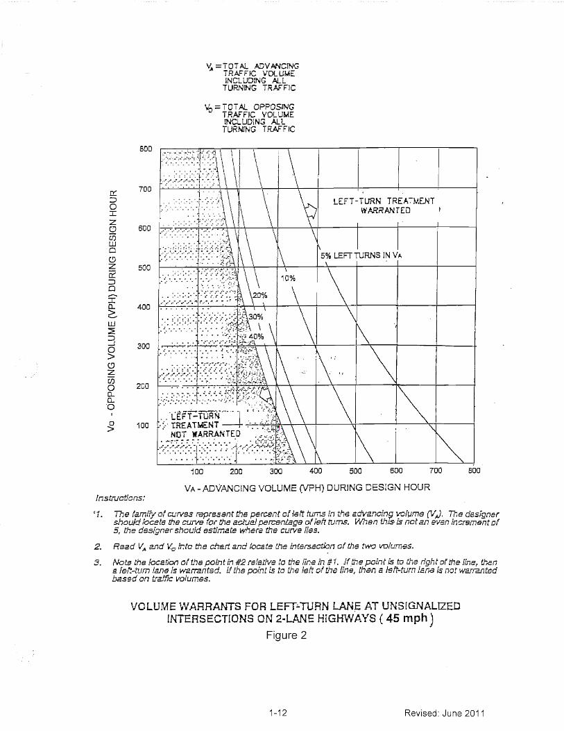
FIGURE 2—Volume Warrants for Left-Turn Lane at Unsignalized Intersectionon 2-Lane Highways (45 mph) ............................................................................ 1-12
FIGURE 3—Volume Warrants for Left-Turn Lane at Unsignalized Intersectionon 2-Lane Highways (50 mph) ............................................................................ 1-13
FIGURE 4—Volume Warrants for Left-Turn Lane at Unsignalized Intersectionon 2-Lane Highways (55 mph) ............................................................................ 1-14
FIGURE 5—Volume Warrants for Left-Turn Lane at Unsianalized Intersectionon 2-Lane Highways (60 mph) ............................................................................ 1-15
1-1 Revised: June 2011
Section 'I Introduction
Private developments are increasingly being proposed throughout the rural areasof Los Angeles County, along highways that are not built to ultimate width and/orlack exclusive left-turn lanes. Many of these proposed projects, once analyzed,could benefit from the installation of a exclusive left-turn lane on the frontageroadway to facilitate ingress vehicular movement at the project's access point.
The refuge area provided by exclusive left-turn lanes can also lead to enhancedtraffic operation by minimizing potential conflicts between various users of theroadway.
These guidelines have been established for the following reasons:
o To assist in the formulation and preparation of conditions ofapproval for tentative maps, parcel maps, and plot plans(associated with conditional use permits and other single-lotdevelopments, subject to conditions).
o To provide a standardized approach in analyzing the need forimplementation of left-turn lanes on two-lane rural highwaysfronting private developments.
These guidelines shall be applicable for all private developments, subject todiscretionary approval or those projects subject to improvement requirementsunder Los Angeles County Code Title 22, Chapter 22,48, Part 4(Section 22.48.220, et seq.). For projects where a detailed traffic study isrequired by the County of Los Angeles Department of Public Works Traffic andLighting Division, an analysis of the sight distance and traffic volumes at theproposed access point, based on these guidelines, should be included in thestudy to verify if the need for a dedicated left-turn lane exists.
The following references were used to develop these left-turn laneimplementation guidelines:
o Los Angeles County Code Title 21o Los Angeles County Code Title 22o AASHTOo California Department of Transportation (Caltrans) Highway Design
Manualo Harmelink, M.D., Aspects of Traffic Control Devices: Volume
Warrants for Left-Turn Storage Lanes at Unsignalized GradeIntersections, Highway Research Board Report No. 211,Washington, DC, Highway Research Board, National ResearchCouncil, 1967,
1-2 Revised: June 2011

Design speeds and the corresponding sight distance criteria utilized for theseguidelines are based on standards referenced in Chapter 200 of the CaltransHighway Design Manual. Minimum design speeds assigned for eachclassification of roadway, as referenced in these guidelines, are based on currentdesign practices being used at the County of Los Angeles Department of PublicWorks (Public Works).
This chapter will be a living document and may be periodically revised orupdated.
Section 2 Left-Turn Lane Implementation Guidelines
This section establishes prescribed steps to be used in evaluating whetherconditions related to the implementation of left-turn lanes on rural two-lanehighways, fronting proposed developments within the County of Los Angeles,should be imposed.
The main factors identified in these guidelines that contribute to the need for left-turn lane implementation are the design speed of the fronting roadway; stoppingsight distance (both horizontal and vertical) at the project's access point; and thecorrelation between the opposing, advancing, and left-turn projected trafficvolumes, post-project implementation, as analyzed at the project access point.
A step-by-step process to evaluate these factors can be found on the followingpages:
The guidelines found in this chapter shall in no way preclude the use ofsound engineering judgment in analyzing the need for left-turn laneimplementation at a particular project entrance. Each project shall bereviewed on a case-by-case basis and be thoroughly evaluated todetermine if a left-turn lane should be installed or not. Other factors thatshould be taken into consideration that are outside the scope of thischapter include, but are not limited to, accident history, existing trafficoperations, and other geometric constraints in the general vicinity of theproposed project In addition, due to the uniqueness of each project,imposing vehicular access restrictions at a particular project site may benecessary and this manual shall not preclude Public Works fromconditioning a project in this manner.
1-3 Revised: June 2011
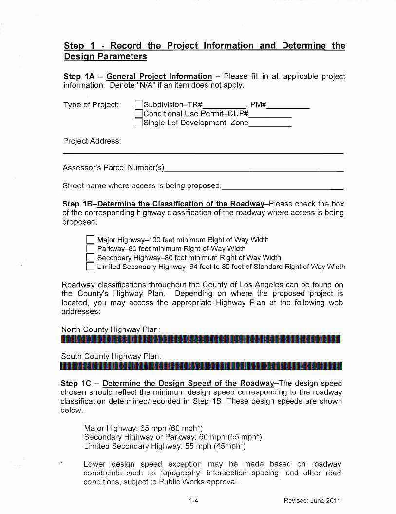
Step I - Record the Project Information and Determine theDesign Parameters
Step IA — General Project Information — Please fill in all applicable projectinformation. Denote "N/A" if an item does not apply.
Type of Project: Subdivision—TR# , PM#Conditional Use Permit—CUP#Single Lot Development—Zone
Project Address:
Assessor's Parcel Number(s)
Street name where access is being proposed:
Step I B—Determine the Classification of the Roadway—Please check the boxof the corresponding highway classification of the roadway where access is beingproposed
Major Highway-100 feet minimum Right of Way WidthParkway-80 feet minimum Right-of-Way WidthSecondary Highway-80 feet minimum Right of Way WidthLimited Secondary Highway-64 feet to 80 feet of Standard Right of Way Width
Roadway classifications throughout the County of Los Angeles can be found onthe County's Highway Plan. Depending on where the proposed project islocated, you may access the appropriate Highway Plan at the following webaddresses:
North County Highway Plan:http://plannind.lacounty.gov/assets/upl/data/map t04-hwy-plan-north-existing.pdf
South County Highway Plan:http://plannind.lacounty.qov/assets/upl/data/map t05-hwy-plan-south-existind.pdf
Step IC — Determine the Design Speed of the Roadway—The design speedchosen should reflect the minimum design speed corresponding to the roadwayclassification determined/recorded in Step 1B. These design speeds are shownbelow.
Major Highway: 65 mph (60 mph*)Secondary Highway or Parkway: 60 mph (55 mph*)Limited Secondary Highway: 55 mph (45mph*)
Lower design speed exception may be made based on roadwayconstraints such as topography, intersection spacing, and other roadconditions, subject to Public Works approval.
1-4 Revised: June 2011

Please record the design speed of the roadway below:
The Design Speed of(Name of Roadway where Access is Being Proposed)
is mph.
Step 2 — Analyze the Horizontal and Vertical Stopping SightDistance
Stopping sight distance as defined in the Caltrans Highway Design Manual is thedistance required by the driver of a vehicle traveling at a given speed to bring thevehicle to a stop after an object on the road becomes visible.
Line of sight should be based on the minimum design speeds for each roadwayclassification as determined in Step 10 above.
Table 1 below shows the stopping sight distance lengths for correspondingdesign speeds based on standards referenced in Chapter 200 of the Ca!transHighway Design Manual. The values shown should be increased by 20 percenton sustained downgrades steeper than 3 percent and longer than one mile to beconsistent with the Caltrans standard found in the Highway Design Manual.
Table I — Stopping Sight Distance Standards
Design Speed( MPH)
Stopping SightDistance (ft) 1
65 66060 58055 50050 43045 36040 30035 25030 20025 15020 125
Since the purpose of this chapter is to evaluate if a left-turn lane is necessaryconsidering current and projected vehicular traffic conditions, the measurementof stopping sight distance is essentially from the driver's eye of one vehicle to thebumper of another vehicle. Therefore, the evaluation of stopping sight distancewithin the context of this chapter should utilize a driver's eye and the target objectheight of 3.5 feet and 2.0 feet above the surface of the roadway respectively.
Stoppin g, sight distance values are based on CALTRANS Highway Design Manual, January 4, 2007edition, Table 2011..
1-5 Revised: June 2011

An appropriate line-of-sight exhibit analyzing the horizontal and vertical stoppingsight distance in both directions should be submitted for evaluation along with theproposed plot plan. The line-of-sight exhibit should show the location of the backbumper for the left-turning vehicle (vehicle 1), which is presumed to be located inthe center of the travel lane, 20 feet (for a typical passenger car) back from thenearside curb prolongation of the proposed driveway. Should the proposed useof the site involve vehicles other than typical passenger cars, the assumedlocation of the back bumper of vehicle 1 would change accordingly based on thetypical length of the project's design vehicle. Design vehicle lengths should beobtained from AASHTO's, A Policy on Geometric Design of Highways andStreets (latest edition). In addition, the line-of-sight exhibit should show thedrivers eye for the advancing vehicle (vehicle 2), which can be presumed to be3.5 feet above the pavement surface, 4 feet from the centerline (or center laneli ne as appropriate), and positioned at the appropriate stopping sight distance (asdetermined from Table 1 above) away from the back bumper of vehicle 1.
The use of stopping sight distance shall be based on the evaluation of theexisting and proposed field conditions and constraints subject to Public Works'review and approval.
Sight Distance Evaluation Outcome Based on Table 1:
Is There AdequateSight Distance? Action To Be Taken
No Exclusive Left-Turn Lane should beinstalled on the fronting roadway
Yes Continue evaluation with STEP 2
Please note that a similar analysis should be performed to evaluate the stoppingsight distance between the driver's eye of vehicle 1 and the front bumper orconflict point of a vehicle traveling in the opposite direction, vehicle 3. Ifadequate stopping sight distance cannot be achieved between a vehicle makinga left turn (vehicle 1) and an on-coming vehicle (vehicle 3) then additional trafficcontrol measures such as a traffic signal should be considered. If said measurecannot be achieved or is not warranted, access restrictions may be imposed.
Step 3 — Analyze the Correlation between Opposing Volume, Advancing Volume, and Left-Turn Volumes for a Given Design Speed
The relationship between the opposing traffic volume 2 , advancing traffic volume3left-turn volume 4 , and design speed is critical in determining if a left-turn lane is
2 Opposin g_ traffic volume as used in this context shall refer to the volume of traffic that is traveling in theopposite direction of where a left-turn lane is bein g, considered at the proposed project access point.' Advancin g, traffic volume as used in this context shall refer to the volume of traffic that is travelinL, in thesame direction of where the left-turn lane is being considered at the proposed project access point.
Left-turn volume as used in this context shall refer to the volume of traffic that is anticipated to make aleft-turn into the proposed project access point.
1-6 Revised: June 2011

warranted at a proposed driveway or street along an two-lane rural undividedhighway and can be evaluated by using the appropriate Harmelink nomographshown in Figures 1 through 5 on the following pages. These nomographs weredeveloped by M.D. Harmelink (documented in the Aspects of Traffic ControlDevices: Volume Warrants for Left-Turn Storage Lanes at Unsignalized GradeIntersections, Highway Research Board Report No, 211, Washington, DC,Highway Research Board, National Research Council, 1967). Thesenomographs have been accepted as a basic guideline by other entities and areincluded in publications developed by other states. Instructions on how to utilizethese nomographs to determine the minimum threshold for which a left-turn laneshould be implemented can be found under each figure. Please note that due tothe absence of a 65 mph nomograph the 60 mph nomograph may be used forevaluation of roadways with a 65 mph design speed.
Examples on how to use the nomographs can be found below. The TotalAdvancing Volume (VA) and the Total Opposing Volume (Vo) values referencedare to be provided by the applicant using volumes obtained from a current trafficcount in the vicinity of the proposed project. Said traffic counts should beperformed from an independent traffic count company at the applicant's expense.These traffic counts are to be taken along the property frontage in the vicinity ofthe proposed project access during the AM and PM peak hours on appropriatedays as determined by Public Works. The Total Left-turn Volumes, (V L ) should beprojected for the project build out year by the applicant using an independenttraffic consultant. For projects with a build out year of 2015 or beyond, theapplicable traffic volume growth factor, which can be found in Table 2 of thischapter, shall be applied. The design speed as referenced in the followingexamples is the speed determined in Step 1C above.
Example
Determined Values as indicated above:O Design Speed = 50mphO Total Advancing Volume including all turning movements, VA=
480vphO Total Opposing Volume including all turning movements, Vo=96vphO Total Left-turn Volumes into the project site for the projected build
out year, V L = 50vph
Project Location = Agoura HillsBuild out Year = 2020
Analyze:If an exclusive left-turn lane into the project site is warranted.
Solution:Step A: Determine the applicable Traffic Volume Growth Factor from
Table 2.
The corresponding Growth Factor from Table 2 for a buildoutyear of 2020 in the City of Agoura Hills is 1.041
1-7 Revised: June 2011

Step B: Apply the growth factor found in Step A to the total advancingand opposing volumes determined from a traffic count company.
Total Advancing Volume with ambient growth factor applied:VA = 480vph x 1.041 = 500vph
Total Opposing Volume with ambient growth factor applied:Vo=96vph x 1.041 = 100vph
Step C: Calculate the percentage of left-turns.(VL / VA ) X 100 =
(50vph / 500vph) x 100 =0.10 x 100 = 10%
Step D: Using Figure 3, find the intersection point of VA (500vph) andVo (100vph).
Step E: Determine the location of the point found in Step D relative to the10% curve found in Step C. If the intersection point lies to theright of the curve then a left-turn lane is warranted based onvolumes. If it lies to the left of the curve then a left-turn lane isnot warranted based on volumes. In this case, the intersectionpoint of VA (500vph) and Vo (100vph) lies to the right of the 10%curve on Figure 3 and, therefore, a left-turn lane is warranted.
Example 2 below utilizes the same values as Example 1; however, this methodcompares the actual percentage of vehicles making a left-turn to the percentagefound to be the threshold for warranting a left-turn lane. As in Example 1,Example 2 shows the same outcome; a left-turn lane is warranted.
Example 2
Determined Values as indicated above:O Design Speed = 50mphO Total Advancing Volume including all turning movements,
VA= 480vphO Total Opposing Volume including all turning movements, V0=96vph
Total Left turn volumes into the project site for the projected buildout year, VL = 50vph
Project Location = Agoura HillsBuild out Year = 2020
Analyze:If an exclusive left-turn lane into the project site is warranted.
Solution:
Step A: Determine the applicable Traffic Volume Growth Factor fromTable 2.
1-8 Revised: June 2011

The corresponding Growth Factor from Table 2 for a build outyear of 2020 in the City of Agoura Hills is 1,041.
Step B: Apply the growth factor found in Step A to the total advancingand opposing volumes determined from a traffic count company.
Total Advancing Volume with ambient growth factor applied:VA = 480vph x 1.041 = 500vph
Total Opposing Volume with ambient growth factor applied:V0=96vph x 1.041 = 100vph
Step C: Using Figure 3, find the intersection point of VA (500vph) andVo (100vph) and determine the corresponding "percentage left-turn curve" that applies (e.g., determine the curve that wouldpass through the intersection point). In this case, thecorresponding percentage of left-turns that would warrant a left-turn lane would be approximately 8,5%.
Step ID: Determine the actual percentage of left turns based on thedetermined values of the total advancing volume (V A) and thetotal left-turn volumes, (Vo.
(VL / VA ) X 100 =
(50vph / 500vph) x 100 =0.10 x 100 = 10%
Step E: Compare the actual percentage of left turns as determined inStep D with the percentage of left turns that would warrant a left-turn lane as determined in Step C. In this case, the actual left-turn volume of 10% is higher than 8.5% (which is the thresholdfor which a left-turn lane is warranted); therefore, the projectshould install a left-turn lane.
Example 3 below, again utilizes the same volumes as both Example 1 and 2;however, this method compares the actual volume of vehicles making a left-turnto the volume found to be the threshold for warranting a left-turn lane. Theoutcome of Example 3 is the same as that of the preceding examples; a left-turnlane is warranted.
Example 3
Determined Values as indicated above:O Design Speed = 50mphO Total Advancing Volume including all turning movements, VA=
480vpho Total Opposing Volume including all turning movements, Vo=96vpho Total Left-turn volumes into the project site for the projected build
out year, VL 50vph
1-9 Revised: June 2011

Project Location = Agoura HillsBuild out Year = 2020
Analyze:If an exclusive left-turn lane into the project site is warranted.
Solution:
Step A: Determine the applicable Traffic Volume Growth Factor fromTable 2.
The corresponding Growth Factor from Table 2 for a build out yearof 2020 in the City of Agoura Hills is 1.041.
Step B: Apply the growth factor found in Step A to the total advancing andopposing volumes determined from a traffic count company.
Total Advancing Volume with ambient growth factor applied:VA = 480vph x 1.041 = 500vph
Total Opposing Volume with ambient growth factor applied:V0=96vph x 1.041 = 100vph
Step C: Using Figure 3, find the intersection point of VA (500vph) and Vo(100vph) and determine the corresponding "percentage left-turncurve" that applies (e.g., determine the curve that would passthrough the intersection point). In this case, the correspondingpercentage of left-turns that would warrant a left-turn lane wouldbe approximately 8.5%.
Step D: Determine the volume threshold for which a left-turn lane wouldbe warranted by multiplying the approaching volume (VA) by thepercentage found in Step C.
VA x8.5%500vph x (8.5/100) =500vph x 0.085 =42.5 vph
Step E: Compare the actual volume of left turns (VL) with the volume ofleft turns that would warrant a left-turn lane as determined in StepD. In this case, the actual left-turn volume of 50 vph is higherthan 42.5vph, which is the threshold for which a left-turn lane iswarranted; therefore, the project should install a left-turn lane.
1-10 Revised: June 2011

VA = TOTAL ADVANCINGTRAFF)C VOLUMEINCLUDING ALL
TURNING TRAFFIC
Vo = TOTAL. OPPOSINGTRAFFIC VOLUMEINCLUDING ALLTURNING TRAFFIC
60
700
600InLi
0e 500
Li
>400
300
In
a_ 200
10
1 00
,,-..,
1 LEFT-TURN
1 •1A ? IRTEEATwa M E N TD
Ir., 1:4,:'• : ,,ZI .;-, a
' • . .....,.. --'n'r1.7;
.4
- 0-,
iZfrq...r''
Z ,..Z.,;,:'..i..“."..k:`,,::.;::::',Z rqfg.-k.,:tc,:.•,..7;1;F:1-.4.4
••',-;.i. • , 1/4` 1., . "'"1,- ''',
,.:,...:.
-,...,
...: i.301aviori1, A,.._Li._.,......,,-,0, .
- LEF f-TurN..,...,-::, TREATMENT
.7 .,_,-,.r... „....,. ..,.,,,.„.. .....,;,„,,.:.,,. _• - 4plikki uit
, k..., .t,
TED
'.. . C7.4'
.1 . 7.'
,
-1•- NOT WARRAN
■ :i;l1r;,,..
-1,-...;-4-,-,
1.'4 4 ' .r... '..,
111 00 200 300 400 500 500 700 800
' VA—ADVANCING VOLUME (VPH) DURING DESIGN HOURInstructions:
1. The family of curves represent the percent of left turns in the advancing volume (VA). The designershould locate the curve for the actual percentage of left turns. When this is not an even increment of5, the designer should estimate where the curve lies,
2. Read V, and V, into the chart and locate the intersection of the two volumes.
3. Note the location of the point in #2 relative to the line in #1. If the point is to the right of the line, thana left-turn lane is warranted. If the point is to the left of the line, then a left-turn lane is not warrantedbased on traffic volumes.
VOLUME WARRANTS FOR LEFT-TURN LANE AT UN SIGNALIZEDINTERSECTIONS ON 2-LANE HIGHWAYS (40 mph)
Figure 1
1-11 Revised: June 2011
700
600
500
400
300
200
100
. . .::::*:•'...
. ' ..• '.
. - •:. : -. .-
-.-.- . .
•.............. - \
LEFT-TURNWARRANTED
TREATMENTi
.• .. •• • ... . -•• •.°-•• - -...• •
• °. •• "::.. „..' • ° • -
5% LEFT TURNS1
I N VA
10%
..........................J... •
. . . ..- .- C:••• ;...-......:. . ....,... . . . . :...
1 •-,•-•._•-.1-•••
..
, \
30%
• \40%
•••_". \. .. ............ ..... . : .. •
........,.° - • • • • • • • • -
.
: : :.:-. -... : . : . t . .'•
....LeF T -TURN•::' T.REATMENT
-,
7:7 7 7 :
,.. .............
NOT WARRANTED
:. '''.4. •
: . . : . . . .•
1,
:
.. . -
• :.:-:.:,f;...
\
800
= TOT AL ADVANCINGTRAFFC vpLuME-_-INCLUDINS ALL
TURNING TRAFT1C
=TOTAL. OPPOSINGTRAFFiC VOLUMEENCLUDING ALLTURNING TRAFFIC
100 200 300 400 500 600 700 800
VA -ADVANCING VOLUME (VPH) DURING DESIGN HOURInstructions:
l. The f2.177ily Of curves represent the percent of left turns in the advancin volume (VA). The desibnershould locate the curve for the actual percenLage of left turns. When thIS. is not an even increment of
the des/crier should estimate enere the curve lies.
2. Read V, and V, into the chart and locate the intersection of the two volumes.
3. Note the location of the r.)oint #2 relative to the line in #1. if the point is to the richt of the line, thena left-turn lane is warranted. lithe ,00int Ls to the left of the line, then a left-turn lane is not warrantedbased on traffic volumes.
VOLUME WARRANTS FOR LEFT-TURN LANE AT UNSIGNALIZEDINTERSECTIONS ON 2-LANE HIGHWAYS ( 45 mph )
Figure 2
\10
1-12 Revised: June 2011

..f,
— ...,—..,-..,—*—......,—,
1,•..,■.C.;,...—;;;,71:1;1.:;;1.....r;
-;:.-- -.-.,- -.
..,--,-1.,,,I,
,
-.ri..7 , •
....g,..2
LEFT.. TURN TREATMENT
WARRANTED
\....4t,,.-7,4.v;- ;
• ,,....-
5% LEFT-TURNS I N VA.-.,
11
-,—1 0
20%
%
.:
41; 30
- ...
r,r-
.., .':•,..‘;1,';
07--:•s
.
a .
LET-URNE), TREATMENT
NOT WARRANTED
,.
1
, .
--;i• ri"4-c
. .,,,-,....„...-
800
700
600
500
400
LLJ
—1o 300
200
1 00
=TOTA._ ADVANCINGTRAFFIC VOLUMEINCLUDING ALLTURNING TRAFFIC
=TOTAL OPPOSINGTRAFFIC VOLUMEINCLUDING ALLTURNING TRAFFIC
V,-
1 00 200 .300 400 500 600 700 800
VA — ADVANCiNG VOLUME t VPH) DURING DESIGN HOUR
instructions:
1. The family of curves represent the percent of left turns in the advancing volume (VA). The designershould locate the curve for the actual percentage of left turns. When this is not an even increment of5, the designer should estimate where the curve lies.
2. Read V, and V, into the chart and locate the intersection of the two volumes.
3. Note the location of the point in #2 relative to the line in #1. if the point is to the right of the line, thena left-turn lane is warranted. If the point is to the left of the line, then a left-turn lane is not warrantedbased on traffic volumes.
VOLUME WARRANTS FOR LEFT-TURN LANE AT UNSIGNALIZEDINTERSECTIONS ON 2-LANE HIGHWAYS (50 mph)
Figure 3
1-13 Revised: June 2011

T D T gs-2_ AO'
," -�.--NC-ThK.:
TR,=-77)C. VD' lik4E.INCL L C; LL
TURNING TR .4=1: ::-- ) C
!- =TCTQ OPP SiNGTF Fi
r YC UE
7 UR ?=g;,-,-) 1'7 TRAFC,
BOO
700
500
r.Z.)500
IL=
400
_J500
r.r)o 200D._
ED
100
.?..,: :z.r.-i7 ; ..• , 7
.s.- ..,... :F
. . ,..'.__
\ \ \\
,..\\
\
..........::::::.1.:\
.... \\
.,
iN.
I E
f`..._/
F T - TviliARN.R
.
ANT RTEE.k.DT_V_E_N. I_
r.....:‘.:....,:::::_,:_ i...._....:1\ \ \ \....._"....._...._/,,.._:::::__\..f
.
,.
;- -•.+.\
r:* -.\
5 % LEFT-TURNS [N V.,
1 I....
r .. • - •:. ... ,... 4.-7 -, • -- '2,
, . ..,J O ic
\1,1r; -. . ,. • : ..'..•••:;7:'..:.'-...-:: ",:l
\\ I \ , N ;-- i.., .'. ..: ; ... 7---,
...:!..7,-::.:':::::: \
-- II : -.. .:\ , \.\
1.\\ \ \., ,r.-::-...•:-...-:1• .: , , .• • "ri., , , \
\- ' '
\. • -'* "",.11_r 1_ 7 \ \I-- --* -. ' 7:-. '. ': :•--- ''...::1:-. : r‘ \
\\
f.:-.:".........1, f,-: ...----'17 \ \. ‘
■' - • ., V.7 1 \ , \\
\
:i: L ff -r 'I -TuRNr•.
\ \„ \
\
\I
, ,
\ ,\
TREATME
....` .- - ---r.........f.-:[..-...-....',..... :t
1;"•_..•..r3'...1
';-/Q L:11" WARRANT: U 4,NT _.
..\
\ N-.L---:_y\ \
- • - •• r :\ \ \\ \
: ,,, - • -, \ • \
\\ \,
„1 ‘•\'........ A............................... \.....................■F --.. :_,:-..-:::.-.:%.7-."-. 7::::" . -.1-'...' 6 ' ______ ---
'-''-
100 200 300 500 D J
— VANT-NG VOLUE DUNG DE SiL
IN HOUR
The fer7Thy Of r-f_TY'SS the o[ie ,ft.uris in thr-_-: edvecing rott,it7e. (Vi J. 7-7Te soneroJd b ee: the CUT-4,43 fOr the a f_-= Je 1LO o( loft Li,7s. EVE11-i
5, Z-17 d.:...-=',SiOriEr she tie' e50TEfO eere the curve
Need E-,--J d (r".", 1.7 ta OIIErt ee h rsz-_---..stic-1-7 t.he VC-ILZME-S.
Note the ioc2t.ior, of ti poTh E in. #2 rslecva to roe fine in ff .ne ,onThs ro :he
. dont or the
l&•,t-turri aTIE-- is point is to fi-;_
=3 of th:_'; 17,r7o, Th&riDEEEO LI JUJC vehJrns-s.,
VOLUME WARRANTS FORF.-FT-YU N LANE AT U.N31CNAL17;7:71
INTERSECTIONS ON 2-LN--1 7-- HIGHWAYS (7 55 rilD1-0
Figure 4
1-14 Revised: June 2011

VA =TOTAL ADVANCINGTRAFFIC VOLUMEINCLUDING ALL
TURNING TRAFFIC
800
700
600
Lii
500
a_ 400
Lii
o 300
(.7)o_a_
2000
>o
1 00
=TOTAL OPPOSINGTRAFFIC VOLUMEINCLUDING ALLTURNING TRAFFIC
2- 2-::::.:,*''`i:',--'''
.:
ILEFT
WARRANTEDTURN TREATMENT
i-:■-■
.1
.20%
le/ 5% LEFT TURNS0
IN VA
' Cf/. .. III
.„.„..„,,,,.:::,,,,,:,:„'LEFT-TURNTREATM
_ENT
NOT WARRANTED-E=.
.- r ,,,
•I
a kAlma'1111
i iekvim.
, 71 00 200 300 400 500 600 700 800
VA— ADVANCING VOLUME (VPH) DURING DESIGN HOUR
Instructions:
1. The family of curves represent the percent of left turns in the advancing volume (V A). The designershould locate the curve for the actual percenta ge of left turns. When this is not an even increment of5, the designer should estimate where the curve lies.
2. Read VA, and V, into the chart and locate the intersection of the two volumes.
3. Note the location of the point in #2 relative to the line in #1. If the point is to the right of the line, thena left-turn lane is warranted. If the point is to the left of the line, then a left-turn lane is not warrantedbased on traffic volumes.
VOLUME WARRANTS FOR LEFT-TURN LANE AT UNSIGNALIZEDINTERSECTIONS ON 2-LANE HIGHWAYS (60 mph)
Figure 5
1-15 Revised: June 2011

Table 2 - Traffic Volume G
rowth Factors
Com
poundC
ompound
Com
poundC
ompound
Com
pound111■
1•1
11
11
•11
,
kePregentati 4
AnnualA
nnualA
nnual,A
nnualA
nnualC
ity/Place2010
Grow
th (%)
2015G
rowth (%
)2020
Grow
th (%)
2025G
roWth('it)
2030G
rowth (%
)2035
.
Agoura H
ills1.000
0.401.020
0.411.041
0.2
11.052
,0.2
1:
1.0630.22
1.075,Saiita C
lailta-1.000
2.751.145
'2.41
1.2910.87
1.3480.83
1.4050.78
1.461
Lancaster
1.0003.95
1.2143:29
,,1.427
3.271.676
1.2.80
1.9242A
52.172
Palm
dale
1.0002.55
1.1342.24
1.2671.47
1.363-
1.361.458
1.271.553
Angeles F
orest1.000
2.851.151
2.48,
1.301439
1.3941,30
1.487L
22
1.580
}ilieSt S.F. Valley
,1.000
0.531.027
0.521.054
016
1.068:
0.281.083
0.261.097
Burbank
Li.1.000
0:481.024
'0.48
1.049017
1.0630
.41.077
la
1.092
Sylmar
1.0000.48
1.024,
0,48,
1.0490.42
1.071O
il1.093
0.381.114
Malibu
,,1.000
0,1531.027
.0.52
1.0540.40,
1.0750.3
91.096
0i381.117
Santa M
orka.
1.000„
0.2C1.014
'0.27
1.0280.19
1.0380.21
1.049_
.--U
.1U
1.059
.„ .14:
•'ia .iestIgetm
alL
.A.
1.000y
-40
;1.007
044
1.014010
1.0240.19
1.0340:19
1.044.
,.SQ
pth Bay/4A
X' '
1.000046
1.013,9
.26
1.0260,3.7
1.0350.17
1.0440.17
'1.053
P-ak!$
,We
'ai .e'S
1.000M
O:
1.025!0
:50
1.0510':' -19
1.061.:0:19
1.0710.19.
1.081T;.•,,.11.1:
4A
iilL
on
g.e
l, ach„
1.0001.1116
1.0761.37
1.152,.
0.14.1.160
.0.14
1.1680.15
1.177
YO
KO
1.0001.42
.1.073
1.331.146
0 21.-
1.1580.21
1.1700.20
1..182..,bow
ney1.000
1.021.052
0.971.104
0.221.116
0.201.127
0.211.139
..D
oviirit0Mit.A
.1.000
0.181.009
0.18to
n0,23
1.030!:0
.23
1.042013
1.054
Glendale
1.0000:28
1.0140.26
1.0270.27
1.0410.27
1.0550.2
51.068
,P
asadena1.000
0.811.041
0.781.082
ø0
29
1.0980.31
1.1150.29
1.131
West C
ovina1.000
0.461.023
0.451.046
-03
81.066
0.371.086
-0
37
1.106
Pom
ona
1.0001.57
1. 0811.44
1.161049
1.1900.48
1.2190.47
1.248

Volume Evaluation Outcome Based on Appropriate Harmelink Nomograph:
Is a Left-TurnTreatment Warranted? Action To Be Taken
NoNo action required, Installation of a
Exclusive Left-Turn Lane on thefronting roadway is not necessary
Yes Exclusive Left-Turn Lane should beinstalled on the fronting roadway
Section 3 Project Implementation
This section establishes the procedures and process for the planning andevaluation of implementation of left-turn lanes for private developments fronting atwo-lane, rural highway.
a) Tentative Map Review and Plot Plan Review
All proposed subdivisions and plot plans will be reviewed byPublic Works' Land Development Division, Road and GradingSection, for adherence to the left-turn lane implementation criteriaestablished in these guidelines. The applicant is, however,responsible for coordinating the review with, and incorporatingdesign criterion imposed by, any other agency including, but notli mited to, the Department of Regional Planning and the County ofLos Angeles Fire Department.
All Conditions of Approval related to left-turn lanes at privatedevelopments will be prepared in accordance with these guidelines.
The applicant shall be responsible for preparing and submitting theappropriate engineering plans, studies, and/or analyses to allowadequate review in accordance with these guidelines by PublicWorks staff. In addition, the applicant shall bear the entire costassociated with the preparation of said plans/documents as well asdepositing any necessary funds to allow Public Works' staff torecover the actual costs of review.
Final Engineering
Should a left-turn lane be required of a project, conditions ofapproval will be prepared accordingly and the applicant will be 100percent responsible for submitting the appropriate final engineeringplans. All plans shall be prepared by a licensed Civil Engineer.
1-17 Revised: June 2011

Street Improvement Plans and Striping Plans associated with theimplementation of left-turn lanes at private driveways will bereviewed by the Land Development Division, Road and GradingSection. Grading plans associated with subdivisions andConditional Use Permits (CUP) will also be reviewed by the LandDevelopment Division, Road and Grading Section. However,grading plans associated with single-lot developments (other thanCUPs) will be reviewed by the applicable Building and Safetydistrict office. Plan check fees for road, striping, and grading planswill be based on fee schedules in effect at the time of submittal.
Should additional pavement be necessary to implement a left-turnlane, a soils report or materials test may be needed to adequatelyanalyze the pavement structural sections. Any proposed structuralsection is subject to approval by Public Works' Geotechnical andMaterials Engineering Division, Soils and Geology Section. It isalso the applicant's responsibility to verify the adequacy of theexisting road right of way to accommodate any neededimprovements and to acquire, prior to tentative map approval (forsubdivision related projects), any additional right of way required toimplement the left-turn lane.
The applicant shall be solely responsible for submitting,coordinating, and processing each applicable plan review througheach reviewing division/section.
c) Construction
It is the responsibility of the applicant to apply for and obtain thenecessary encroachment permits for any required work within thepublic right of way and to pay all applicable fees prior to permitissuance.
1-18 Revised: June 2011
Section 4 Acknowledgements
Document Preparation Team
The following were contributing members of a committee that was established forthe sole purpose of formulating this document:
Design Division: Roy Cruz
Land Development Division: Matthew DubielAndy NaragSam Richards
Operational Services Division: David FryerKeith LeeJavier RoblesRobert Scharf
Road Maintenance Division: Jeff Harkins
Traffic and Lighting Division: Gerald LeyJeff Pletyak
1-19 Revised. June 2011

Approved:Dennis Hunter, Deputy Director
County of Los AngelesDepartment of Public Works
Access Management ForPrivate Developments
Guidelines Manual
Chapter 2Right-Turn Lane implement tion
For Private DevelopmentFronting Two-Lane Rural
Undivided Highways
Jiirte 7011

Table of Contents
1) INTRODUCTION .......................................................................................... 2-2
2) RIGHT-TURN LANE IMPLEMENTATION GUIDELINES ........................... 2-3
Step 1—Record the Project Information and Determine the DesignParameters ................................................................................. 2-4Step 1A—General Project Information ........................................ 2-4Step 1B—Determine the Classification of the Roadway .............. 2-4Step 1C—Determine the Design Speed of the Roadway ..... 2-4
Step 2—Analyze the Horizontal and Vertical Stopping Sight Distance 2-5
Step 3—Analyze the Correlation between the Advancing Volume and theRight-Turn Volumes for a Given Design Speed .......... 2-6
3) PROJECT IMPLEMENTATION ................................................ 2-13a) Tentative Map Review and Plot Plan Review ................ 2-13b) Final Engineering ........................................................... 2-13c) Construction ................................................................... 2-14
ACKNOWLEDGMENTS .......................................................... 2-15Document Preparation Team
List of Tables
TABLE 1—Stopping Sight Distance Standards ............................... 2-5
TABLE 2—Traffic Volume Growth Factors ...................................... 2-12
List of Figures
FIGURE 1—Volume Warrant for Right-Turn Lane at UnsignalizedIntersections on 2-Lane Highways ............................................................. 2-11

Section 1 Introduction
Private developments are increasingly being proposed throughout the rural areasof Los Angeles County, along highways that are not built to ultimate width and/orlack exclusive right-turn lanes. Many of these proposed projects, once analyzed,could benefit from the installation of an exclusive right-turn lane on the frontageroadway to facilitate ingress vehicular movement at the project's access point.
The refuge area provided by exclusive right-turn lanes can also lead to enhancedtraffic operation by minimizing potential conflicts between various users of theroadway.
These guidelines have been established for the following reasons:
o To assist in the formulation and preparation of conditions ofapproval for tentative maps, parcel maps, and plot plans(associated with conditional use permits and other single-lotdevelopments, subject to conditions).
o To provide a standardized approach in analyzing the need forimplementation of right-turn lanes on two-lane rural highwaysfronting private developments.
These guidelines shall be applicable for all private developments, subject todiscretionary approval or those projects subject to improvement requirementsunder Los Angeles County Code Title 22, Chapter 22.48, Part 4(Section 22.48.220, et seq.). For projects where a detailed traffic study isrequired by the County of Los Angeles Department of Public Works Traffic andLighting Division, an analysis of the sight distance and traffic volumes at theproposed access point, based on these guidelines, should be included in thestudy to verify if the need for a dedicated right-turn lane exists.
The following references were used to develop these right-turn laneimplementation guidelines:
o Los Angeles County Code Title 21o Los Angeles County Code Title 22o AASHTOo California Department of Transportation (Caltrans) Highway Design
Manualo Traffic Volume Warrants for Right Turn Auxiliary Lanes At
Unsignalized Intersections, (Willey, LB., 1989), in Vermont Agencyof Transportation Guidelines for Engineering Issues, Attachment G,1994,
o Turn Lane Warrants: Concepts, Standards, Application in Review,presented by David J. DeBaie RE., P.T.O.E at the 2004 1TE,District Meeting in Burlington Vermont.
2-2 June 2011

o Harmelink, M.D., Aspects of Traffic Control Devices: VolumeWarrants for Left-Turn Storage Lanes at Unsignalized GradeIntersections, Highway Research Board Report No, 211,Washington, DC, Highway Research Board, National ResearchCouncil, 1967.
Design speeds and the corresponding sight distance criteria utilized for theseguidelines are based on standards referenced in Chapter 200 of the Ca!transHighway Design Manual. Minimum design speeds assigned for eachclassification of roadway, as referenced in these guidelines, are based on currentdesign practices being used at the County of Los Angeles Department of PublicWorks (Public Works).
This chapter will be a living document and may be periodically revised orupdated.
Section 2 Right-Turn Lane Implementation Guidelines
This section establishes prescribed steps to be used in evaluating whetherconditions related to the implementation of right-turn lanes on rural, two-lanehighways, fronting proposed developments within the County of Los Angeles,should be imposed.
The main factors identified in these guidelines that contribute to the need forright-turn lane implementation are the design speed of the fronting roadway;stopping sight distance (both horizontal and vertical) at the project's access point;and the correlation between the advancing and right-turn projected trafficvolumes, post-project implementation, as analyzed at the project access point.
A step-by-step process to evaluate these factors can be found on the followingpages:
The guidelines found in this chapter shall in no way preclude the use ofsound engineering judgment in analyzing the need for right-turn laneimplementation at a particular project entrance. Each project shall bereviewed on a case-by-case basis and be thoroughly evaluated todetermine if a right-turn lane should be installed or not. Other factors thatshould be taken into consideration that are outside the scope of thischapter include, but are not limited to, accident history, existing trafficoperations, and other geometric constraints in the general vicinity of theproposed project. In addition, due to the uniqueness of each project,imposing vehicular access restrictions at a particular project site may benecessary and this chapter shall not preclude Public Works fromconditioning a project in this manner.
2-3 June 2011

Step I - Record the Project Information and Determine theDesign Parameters
Step IA — General Project Information — Please fill in all applicable projectinformation. Denote "N/A" if an item does not apply.
Type of Project:
Project Address:
Subdivision—TR# PM#Conditional Use Permit—CUP#Single Lot Development—Zone
Assessor's Parcel Number(s)
Street name where access is being proposed:
Step I B—Determine the Classification of the Roadway—Please check the boxof the corresponding highway classification of the roadway where access is beingproposed.
Major Highway-100 feet minimum Right of Way WidthParkway-80 feet minimum Right-of-Way WidthSecondary Highway-80 feet minimum Right of Way WidthLimited Secondary Highway-64 feet to 80 feet of Standard Right of Way Width
Roadway classifications throughout the County of Los Angeles can be found onthe County's Highway Plan. Depending on where the proposed project islocated, you may access the appropriate Highway Plan at the following webaddresses:
North County Highway Plan:http://planning.lacounty.gov/assets/upl/data/map t04-hwy-plan-north-existing.pdf
South County Highway Plan:http://planning.lacounty.gov/assets/upl/data/map t05-hwy-plan-south-existing.pdf
Step IC — Determine the Design Speed of the Roadway—The design speedchosen should reflect the minimum design speed corresponding to the roadwayclassification determined/recorded in Step 1B. These design speeds are shownbekm,
Major Highway: 65 mph (60 mph*)Secondary Highway or Parkway: 60 mph (55 mph*)Limited Secondary Highway: 55 mph (45mph*)
Lower design speed exception may be made based on roadwayconstraints such as topography, intersection spacing, and other roadconditions, subject to Public Works approval,
2-4 June 2011

Please record the design speed of the roadway below:
The Design Speed of(Name of Roadway where Access is Being Proposed)
is mph.
Step 2 — Analyze the Horizontal and Vertical Stopping SightDistance
Stopping sight distance as defined in the Caltrans Highway Design Manual is thedistance required by the driver of a vehicle traveling at a given speed to bring thevehicle to a stop after an object on the road becomes visible.
Line of sight should be based on the minimum design speeds for each roadwayclassification as determined in Step 1C above.
Table 1 below shows the stopping sight distance lengths for correspondingdesign speeds based on standards referenced in Chapter 200 of the CaltransHighway Design Manual. The values shown should be increased by 20 percenton sustained downgrades steeper than 3 percent and longer than one mile to beconsistent with the Caltrans standard found in the Highway Design Manual.
Table 1 — Stopping Sight Distance Standards
Design Speed( MPH)
Stopping SightDistance (ft) 1
65 66060 58055 50050 43045 36040 30035 25030 20025 15020 125
Since the purpose of this chapter is to evaluate if a right-turn lane is necessaryconsidering current and projected vehicular traffic conditions, the measurementof stopping sight distance is essentially from the driver's eye of one vehicle to thebumper of another vehicle. Therefore, the evaluation of stopping sight distancewithin the context of this chapter should utilize a driver's eye and the target objectheight of 3.5 feet and 2.0 feet above the surface of the roadway respectively.
Stoppin g, sight distance values are based on CALTRANS Highway Design Manual. January 4. 2007edition. Table 201.1.
2-5 June 2011

An appropriate line-of-sight exhibit analyzing the horizontal and vertical stoppingsight distance in both directions should be submitted for evaluation along with theproposed plot plan. The line-of-sight exhibit should show the location of the backbumper for the right-turning vehicle (vehicle 1), which is presumed to be locatedin the center of the travel lane, 20 feet (for a typical passenger car) back from thenearside curb prolongation of the proposed driveway. Should the proposed useof the site involve vehicles other than typical passenger cars, the assumedlocation of the back bumper of vehicle 1 would change accordingly based on thetypical length of the project's design vehicle. Design vehicle lengths should beobtained from AASHTO's, A Policy on Geometric Design of Highways andStreets (latest edition). In addition, the line-of-sight exhibit should show thedrivers eye for the advancing vehicle (vehicle 2), which can be presumed to be3.5 feet above the pavement surface, 4 feet from the centerline (or center laneli ne as appropriate), and positioned at the appropriate stopping sight distance (asdetermined from Table 1 above) away from the back bumper of vehicle 1.
The use of stopping sight distance shall be based on the evaluation of theexisting and proposed field conditions and constraints subject to Public Works'review and approval.
Sight Distance Evaluation Outcome Based on Table 1:
Is There AdequateSight Distance? Action To Be Taken
No Exclusive Right-Turn Lane shouldbe installed on the fronting roadway
Yes Continue evaluation with STEP 2
Step 3 — Analyze the Correlation between the Advancing Volumeand the Right-Turn Volumes for a Given Design Speed
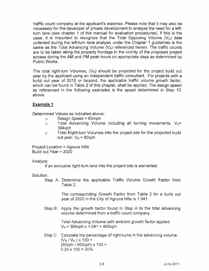
The relationship between the advancing traffic volume 2 , right-turn volume 3 , anddesign speed is critical in determining if a right-turn lane is warranted at aproposed driveway or street along an two-lane rural undivided highway and canbe evaluated by using the Volume Warrant for Right-Turn Lanes at UnsignalizedIntersections for 2-lane Highways as shown in Figure 1 on page 2-11. Thisnomograph was adopted by the Vermont Agency of Transportation (documentedin the Traffic Volume Warrants for Right Turn Auxiliary Lanes At UnsignalizedIntersections, (Willey, L.B., 1989), in Vermont Agency of TransportationGuidelines for Engineering Issues, Attachment G. 1994) and was modified toreflect only the curves related to the two-lane highways. It is based on the sameconcepts used by M.D Harmelink to create the largely popular Harmelinknomographs for left-turn warrants (documented in the Aspects of Traffic ControlDevices: Volume Warrants for Left-Turn Storage Lanes at Unsignalized Grade
2 Advancing traffic volume as used in this context shall refer to the volume of traffic that is travelin g in thesame direction of where the right-turn lane is bein g considered at the proposed project access point.
Ri ght-turn volume as used in this context shall refer to the volume of traffic that is anticipated to make ari ght-turn into the proposed project access point.
2-6 June 2011
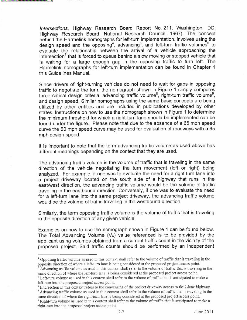
Intersections, Highway Research Board Report No. 211, Washington, DC,Highway Research Board, National Research Council, 1967). The conceptbehind the Harmelink nomographs for left-turn implementation, involves using thedesign speed and the opposing 4 , advancing 5 , and left-turn traffic volumes s toevaluate the relationship between the arrival of a vehicle approaching theintersection 7 that is forced to queue behind a slow moving or stopped vehicle thatis waiting for a large enough gap in the opposing traffic to turn left, TheHarmelink nomographs for left-turn implementation can be found in Chapter 1this Guidelines Manual.
Since drivers of right-turning vehicles do not need to wait for gaps in opposingtraffic to negotiate the turn, the nomograph shown in Figure 1 simply comparesthree critical design criteria; advancing traffic volume s , right-turn traffic volumeg,and design speed. Similar nomographs using the same basic concepts are beingutilized by other entities and are included in publications developed by otherstates. Instructions on how to use the nomograph shown in Figure 1 to determinethe minimum threshold for which a right-turn lane should be implemented can befound under the figure. Please note that due to the absence of a 65 mph speedcurve the 60 mph speed curve may be used for evaluation of roadways with a 65mph design speed.
It is important to note that the term advancing traffic volume as used above hasdifferent meanings depending on the context that they are used.
The advancing traffic volume is the volume of traffic that is traveling in the samedirection of the vehicle negotiating the turn movement (left or right) beinganalyzed. For example, if one was to evaluate the need for a right turn lane intoa project driveway located on the south side of a highway that runs in theeast/west direction, the advancing traffic volume would be the volume of traffictraveling in the eastbound direction. Conversely, if one was to evaluate the needfor a left-turn lane into the same project driveway, the advancing traffic volumewould be the volume of traffic traveling in the westbound direction.
Similarly, the term opposing traffic volume is the volume of traffic that is travelingin the opposite direction of any given vehicle.
Examples on how to use the nomograph shown in Figure 1 can be found below,The Total Advancing Volume (VA) value referenced is to be provided by theapplicant using volumes obtained from a current traffic count in the vicinity of theproposed project. Said traffic counts should be performed by an independent
4 Opposin g_ traffic volume as used in this context shall refer to the volume of traffic that is traveling in theopposite direction of where a left-turn lane is bein g_ considered at the proposed project access point.
Advancing traffic volume as used in this context shall refer to the volume of traffic that is traveling in thesame direction of where the left-turn lane is being considered at the proposed project access point.6 Left-turn volume as used in this context shall refer to the volume of traffic that is anticipated to make aleft-turn into the proposed project access point.7 Intersection in this context refers to the converging of the project driveway access to the 2-lane highway.8 Advancin g_ traffic volume as used in this context shall refer to the volume of traffic that is travelin g, in thesame direction of where the right-turn lane is bein g, considered at the proposed project access point.9 Right-turn volume as used in this context shall refer to the volume of traffic that is anticipated to make aright-turn into the proposed project access point.
2-7 June 2011
traffic count company at the applicant's expense. Please note that it may also benecessary for the developer of private development to analyze the need for a left-turn lane (see chapter 1 of this manual for evaluation procedures). If this is thecase, it is important to recognize that the Total Opposing Volume (V 0) datacollected during the left-turn lane analysis under the Chapter 1 guidelines is thesame as the Total Advancing Volume (VA) referenced herein. The traffic countsare to be taken along the property frontage in the vicinity of the proposed projectaccess during the AM and PM peak hours on appropriate days as determined byPublic Works.
The total right-turn Volumes, (V R) should be projected for the project build outyear by the applicant using an independent traffic consultant. For projects with abuild out year of 2015 or beyond, the applicable traffic volume growth factor,which can be found in Table 2 of this chapter, shall be applied. The design speedas referenced in the following examples is the speed determined in Step 1Cabove.
Example 1
Determined Values as indicated above:o Design Speed = 60mphO Total Advancing Volume including all turning movements, VA=
384vphO Total Right-turn Volumes into the project site for the projected build
out year, VR 80vph
Project Location = Agoura HillsBuild out Year = 2020
Analyze:If an exclusive right-turn lane into the project site is warranted.
Solution.Step A: Determine the applicable Traffic Volume Growth Factor from
Table 2.
The corresponding Growth Factor from Table 2 for a build outyear of 2020 in the City of Agoura Hills is 1.041,
Step B: Apply the growth factor found in Step A to the total advancingvolume determined from a traffic count company,
Total Advancing Volume with ambient growth factor applied:VA = 384vph x 1.041 = 400vph
Step C: Calculate the percentage of right-turns in the advancing volume.(VR / VA ) X 100=(80vph / 400vph) x 100 =0.20 x 100 = 20%
2-8 June 2011

Step D: Using Figure 1, find the intersection point of VA (400vph) and thepercentage found in Step C (20%).
Step E: Determine the location of the point found in Step D relative to the60 mph design speed curve. If the intersection point lies above orto the right of the curve then a right-turn lane is warranted basedon volumes. If it lies below or to the left of the curve then a right-turn lane is not warranted based on volumes. In this case, theintersection point of VA (400vph) and 20% lies above the 60mphdesign speed curve on Figure 1 and, therefore, a right-turn laneis warranted.
Example 2 below utilizes the same values as Example 1; however, this methodcompares the design speed of the roadway to the design speed found to be thethreshold for warranting a right-turn lane. As in Example 1, Example 2 shows thesame outcome; a right-turn lane is warranted.
Example 2
Determined Values as indicated above;O Design Speed = 60mphO Total Advancing Volume including all turning movements, VA=
384vphO Total Right-turn Volumes into the project site for the projected build
out year, VR 80vph
Project Location = Agoura HillsBuild out Year = 2020
Analyze:If an exclusive right-turn lane into the project site is warranted.
Solution:Step A: Determine the applicable Traffic Volume Growth Factor from
Table 2.
The corresponding Growth Factor from Table 2 for a build outyear of 2020 in the City of Agoura Hills is 1,041.
Step B: Apply the growth factor found in Step A to the total advancingvolume determined from a traffic count company.
Total Advancing Volume with ambient growth factor applied:VA = 384vph x 1.041 = 400vph
Step C: Calculate the percentage of right-turns in the advancing volume(VR / VA ) X 100 =
(80vph / 400vph) x 100 =0.20 x 100 = 20%
2-9 June 2011

Step D: Using Figure 1, find the intersection point of VA (400vph) and thepercentage found in Step C (20%) and determine thecorresponding "design speed curve" that applies (e.g., determinethe curve that would pass through the intersection point). In thiscase, the corresponding design speed that would warrant a right-turn lane would be approximately 55mph.
Step E: Compare the actual design speed of the roadway with the designspeed that would warrant a right-turn lane as determined in StepD. In this case, the actual design speed of the roadway (60mph)is higher than 55mph (which is the threshold for which a right-turn lane is warranted); therefore, the project should install aright-turn lane.
2-10 June 2011

5:7)
1,,DIVPN
OMPH
YOMPH
(IR ,) x 100(VA)PERCENTAGE (%) OF RIGHT-TURNS IN
ADVANCING VOLUMES DURING DESIGN HOUR
Instructions:
1. The family of curves represent the design speed of the roadway as determined by thedesigner in Step 1C.
Determine the percentage (%) of right-turns (V R ) in the advancing volumes (V A) during thedesign hour by dividing VR by VA and multiplying this value by 100. Please note VA is the totaladvancing traffic volume including all turning traffic.
Read VA and the percentage into the chart and locate the intersection of the two values.
4. Note the location of the point found in no. 3 above relative to the line described in no, 1above, If the point is above or to the right of the line, then a right-turn lane is warranted basedon traffic volumes. If the point is below or to the left of the line, then a right-turn lane is notwarranted based on traffic volumes,
Volume Warrant for Right-Turn Lane at UnsignalizedIntersections on 2-lane Highways
Figure 1
2-11 June 2011

Tab
le 2 - T
raffic Volu
me G
rowth
Factors
Rep
resentative
comp
oun
d
Annual
Com
pound
Annual
Com
pound•
ttA
nntial
Com
pound
AliU
a I
Com
pound3.
An
nu
l
City/P
li6e2010
Grow
th (%)
2015G
rowth ( A
)2020
Grow
th (%)
2025G
rowth (%
)2030 _ ,
Grow
th (%)
2035
Agoura H
ills1.000
0.401.020
0.4
11.041
04211.052
0.211.063
0.221.075
San
ta Clarita
1.0002.75
1.145243
1.2910.81
1.3480.83
1.4050 78
1.461
Lancaster
1.0003.95
1.2143.29
1.4273.27
1.6762.80
1.9242.45
2.172
Palm
dale1.000
2.551.134
2.241.267
1.471.363
1.361.458
1.271.553
An
geles,Fgrest
1.0002.85
1.1512.48
1.3011.39
1.3941.30
1.4871.22
1.580
West SF. V
alley1.000
0.531.027
0.521.054
0.261.068
1281.083
0.261.097
.B
urbank,
1.0000:48
1.024148
1.0490.27
1.0630.26
1.0770.28
1.092
..y.t i. 6r
1.0000.48
1.0240A
81.049
0.421.071
0:411.093
0.381.114
MO
O1.000
.1531.027
062
1.0540.4o
1.0750.39
1.0960i-38
1.117....,:.„.
,S
anta Monica
1.0000.28
1.0140.27
1.0280.19
1.0380.21
1.0490.19
1.059
wof entiiictia,
1.0000
44
1.007014
1.014.0.20
1.024Oel.9.
1.0340.19
1.044
Soiiiii payAm
1.0000.26
1.0130.26
1.0260.17
1.0356
33
1.0440.17
1.053
PalO
g: Odes,
1.000:0
,50
1.0250S
01.051
0.191.061
0:191.071
1191.081
Long,iiqpch1.000
1.481.076
1.371.152
0.141.160
0.141.168
0.151.177
Veit on
tom
1.421.073
1.33-1.146
0.211.158
0.211.170
0201.182
Dow
ney1.000
1.021.052
0.971.104
0. 21.116
0.201.127
0.211.139
Dow
ntown L
.A,
1.0000.18
1.009,--
118to
n:0.23
1.030123
1.042023
1.0544.
Glendale
1.0000.28
1.014026
1.0270.27
1.0410.27
1.0550.25
1.068
Pasadena
1.0000.81
1.0410:18
1.0820.29
1.0980.31
1.1150:29
1.131
West C
ovina1.000
,0.4
61.023
145
1.046048
1.0660.37
1.0860.37
1.106
Pom
ona1.000
1.571.081
1.441.161
0.491.190
0:481.219
0.471.248

Volume Evaluation Outcome Based on Nomograph shown in Figure 1:
Is a Right-TurnTreatment Warranted? Action To Be Taken
NoNo action required, Installation of aExclusive Right-Turn Lane on thefronting roadway is not necessary
Yes Exclusive Right-Turn Lane shouldbe installed on the fronting roadway
Section 3 Project Implementation
This section establishes the procedures and process for the planning andevaluation of implementation of right-turn lanes for private developments frontinga two-lane rural highway.
a) Tentative Map Review and Plot Plan Review
All proposed subdivisions and plot plans will be reviewed byPublic Works Land Development Division, Road and GradingSection, for adherence to the right-turn lane implementation criteriaestablished in these guidelines. The applicant is, however,responsible for coordinating the review with, and incorporatingdesign criterion imposed by, any other agency including, but notli mited to, the Department of Regional Planning and the County ofLos Angeles Fire Department.
All Conditions of Approval related to right-turn lanes at privatedevelopments will be prepared in accordance with these guidelines.
The applicant shall be responsible for preparing and submitting theappropriate engineering plans, studies, and/or analyses to allowadequate review in accordance with these guidelines by PublicWorks staff. In addition, the applicant shall bear the entire costassociated with the preparation of said plans/documents as well asdepositing any necessary funds to allow Public Works' staff torecover the actual costs of review.
b) Final Engineering
Should a right-turn lane be required of a project, conditions ofapproval will be prepared accordingly and the applicant will be 100percent responsible for submitting the appropriate final engineeringplans. All plans shall be prepared by a licensed Civil Engineer.
2-13 June 2011

Street Improvement Plans and Striping Plans associated with theimplementation of right-turn lanes at private driveways will bereviewed by the Land Development Division, Road and GradingSection. Grading plans associated with subdivisions andConditional Use Permits (CUP) will also be reviewed by the LandDevelopment Division, Road and Grading Section. However,grading plans associated with single-lot developments (other thanCUPs) will be reviewed by the applicable Building and Safetydistrict office. Plan check fees for road, striping, and grading planswill be based on fee schedules in effect at the time of submittal.
Should additional pavement be necessary to implement a right-turnlane, a soils report or materials test may be needed to adequatelyanalyze the pavement structural sections. Any proposed structuralsection is subject to approval by Public Works' Geotechnical andMaterials Engineering Division, Soils and Geology Section. It isalso the applicant's responsibility to verify the adequacy of theexisting road right of way to accommodate any neededimprovements and to acquire, prior to tentative map approval (forsubdivision related projects), any additional right of way required toimplement the right-turn lane.
The applicant shall be solely responsible for submitting,coordinating, and processing each applicable plan review througheach reviewing division/section,
c) Construction
It is the responsibility of the applicant to apply for and obtain thenecessary encroachment permits for any required work within thepublic right of way and to pay all applicable fees prior to permitissuance,
2-14 June 2011

Section 4 Acknowledgements
Document Preparation Team
The following were contributing members of a committee that was established forthe sole purpose of formulating this document:
Design Division: Roy Cruz
Land Development Division: Matthew DubielAndy NaragSam Richards
Operational Services Division: David FryerKeith LeeJavier RoblesRobert Scharf
Road Maintenance Division: Jeff Harkins
Traffic and Lighting Division: Gerald LeyJeff Pletyak
2-15 June 2011