access control system - soyal.com · soyal access control system ® ar-327-e / 727-e v200114 cn4...
TRANSCRIPT
SOYALACCESS CONTROL SYSTEM
®AR-327-E / 727-E
V200114
CN4 CN5 CN7
CN6 CN3 CN2
AR-821RB
AR-821RB
CN4 CN5 CN7
CN6 CN3 CN8
654321
CN11654321
CN9
87654321
CN5
CN3
87654321
CN4
21
CN67654321
CN7
4321
CN8
77665544332211 CN18
CN2
CN18327-E
327-E
727-E
727-E
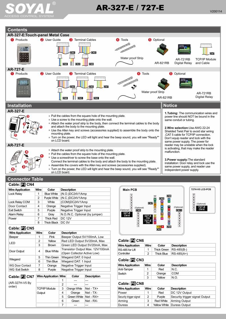
Wire Application Wire Color Description1 --- ---2 --- ---
TCP/IP Module Output
3 Orange White Net - TX+4 Orange Net - TX-5 Green White Net - RX+6 Green Net - RX-7 --- ---
Wire Application Wire Color DescriptionRS-485 for LiftController
1 Thick Green RS-485(B-)2 Thick Blue RS-485(A+)
Wire Application Wire Color DescriptionAnti-Tamper Switch
1 Red N.C.2 Orange COM3 Yellow N.O.
Wire Application Wire Color DescriptionPower 1 Red DC 12V OutputSecurity trigger signal 2 Purple Security trigger signal OutputArming 3 Red White Arming OutputDuress 4 Yellow White Duress Output
(AR-327H-V5 By order)
Wire Application Wire Color DescriptionLock Relay 1 Blue White (N.O.)DC24V1Amp
2 Purple White (N.C.)DC24V1AmpLock Relay COM 3 White (COM)DC24V1AmpDoor Contact 4 Orange Negative Trigger InputExit Switch 5 Purple Negative Trigger InputAlarm Relay 6 Gray N.O./N.C. Optional (by jumper)Power 7 Thick Red DC 12V
8 Thick Black DC 0V
Wire Application Wire Color DescriptionBeeper 1 Pink Beeper Output 5V/100mA, Low
LED 2 Yellow Red LED Output 5V/20mA, Max3 Brown Green LED Output 5V/20mA, Max
Door Output 4 Blue White Transistor Output Max. 12V/100mA (Open Collector Active Low)
Wiegand 5 Thin Green Wiegand DAT: 0 Input6 Thin Blue Wiegand DAT: 1 Input
WG Door Contact 7 Orange Negative Trigger InputWG Exit Switch 8 Purple Negative Trigger Input
(Optional)(Optional) (Optional)
(Optional)
Main PCB 727H-V5 LCD-PCB
1.Tubing: The communication wires and power line should NOT be bound in the same conduit or tubing.
2.Wire selection:Use AWG 22-24 Shielded Twist Pair to avoid star wiring ,CAT 5 cable for TCP/IP connection. Don’t equip reader and lock with the same power supply. The power for reader may be unstable when the lock is activating, that may make the reader malfunction.
3.Power supply:The standard installation: Door relay and lock use the same power supply, and reader use independent power supply.
Attach the water proof strip to the mounting plate.Pull the cables from the square hole of the mounting plate.Use a screwdriver to screw the base onto the wall. Connect the terminal cables to the body and attach the body to the mounting plate.Assemble the covers with the Allen key and screws (accessories supplied). Turn on the power, the LED will light and hear the beep sound, you will see "Ready"" on LCD board.
2 User Guide1 Products 3 Terminal Cables 4 Tools 5 Optional
AR-721RBDigital Relay
Water proof Strip
2 User Guide1 Products 3 Terminal Cables 4 Tools 5 Optional
AR-721RBDigital Relay
TCP/IP Moduleand Cable
Water proof Strip
3
1
2
5
4
3
1
2
4
5
ContentsAR-327-E:Touch-panel Metal Case
AR-727-E
Installation NoticeAR-327-E
Pull the cables from the square hole of the mounting plate. Use a screw to the mounting plate onto the wall. Attach the water proof strip to the body, then connect the terminal cables to the body and attach the body to the mounting plate. Use the Allen key and screws (accessories supplied) to assemble the body onto the mounting plate. Turn on the power, the LED will light and hear the beep sound, you will see "Ready"" on LCD board.
AR-727-E
Connector TableCable: CN4P1
Cable: CN6P4
P2Cable: CN5
P6Cable: CN8
P5Cable: CN3
Cable: CN7P3

V200114
AR-327-E AR-727-E
18/02 FRI Duty:018/02 FRI Duty:0
10:49:34 10:49:34Ready...... Ready......
PWR
ERR
02 24
14 : 49 : 04FRI Duty : 0
12345678
E
12VGND
Exit Switch
12VGND
12VGND
N.O.GND
N.O.
COM
PB
12VGND
CN4
EXIT
12345678
12VGND
12VGND
12VGND
N.O.GND
N.O.
COM
PB
12VGND
CN4
EXIT
Door Contact
ALM12V
GND
12VGND
12VGND
12VGND
N.C.
CN4
N.C.N.O.
COMCTL12V
12345678
12345678
12345678
12345678
E
12VGND
12VGND
12VGND
12VGND
PBPB
COMCOM
N.O.N.O.CN4CN4
12VGND
12VGND
PB
COMN.C.
CN4
EXIT EXITEXIT
EXIT
N.C.COM
PB
12VGND
N.O.
N.O.COMN.C.V+V-
LCD Access Controller
Optional Cables
Connect to Electric BoltWiring Diagram
Controller
RTE
POWER12VDC
POWER12VDC
Controller
RTE
POWER12VDC
POWER12VDC
Magnet Lock
Connect to Magnet Lock
Connect to Electric Strike Connect to Door Contact
Controller
RTE
POWER12VDC
POWER12VDC
Electric Strike
If any fire emergency, the people can escape by press a switch to open all doors
RTERTERTE
POWER12VDC
POWER12VDC
Electric Strike Electric Bolt
Fire Emergency
TransistorIN4007
TransistorIN4007
TransistorIN4007
Magnet Lock
Controller
POWER12VDC
POWER12VDC
Alarm
Relay Outpot Module
Door Contact
Front Panel & IndicatorDataWeekWork Status
Data [e.g.] 02/24←→02 24(Network Connected)WeekWork Shift Status
Esc/Quit
UpDownLeftRightEnter/OK
Power(Green)Alarm(Red)
Arming (Green)
Esc/Quit
Up
Down
Left
Right
Enter/OK
OK(Green)Error (Red)In processing (Green)
Power(Green)Alarm(Red)
Arming (Green)
Wire Application Wire Color DescriptionTTL Port for Lift Control or Voice Module(*Required speaker 8Ω / 1.5W (Max. 2W)
1 Black DC 0V2 Yellow TX3 White TE4 Orange RX5 Red DC 5V6 --- ---
Wire Application Wire Color DescriptionHID ProxII RF Module
1 Orange ANT 12 Purple ANT 23 Black DC 0V4 Red DC 5V5 Blue Wiegand DAT: 1 Input6 Green Wiegand DAT: 0 Input7 White --
Cable: AR-327-E: CN10 / 727(H-V5): CN18 P8Cable: CN11(Optional:Lift Control w/ AR-725L485; SW:RS485-2) P7CN9 (Optional:Voice Module; SW:RS485-3) P9
OK(Green)
Error (Red)In processing (Green)
POWER12VDC
SOYALACCESS CONTROL SYSTEM
®AR-327-E / 727-E
V200114
EXIT
N.C.N.O.
COMCTL12VGND
PB
12VGND
12VGND
N.O.
12VGND
12VGND
DDRCN4
CN8CN2 AR-721RB12V
327H-V5
727H-V5
12345678
1 2 3 4
N.C.N.O.COMCTL12V
E
BZRLEDGLED
WG 112VGND
123
6
12VGNDExit Switch
12VGND
CN5
CN4BZRLEDGLEDDoor OutputWG 0WG 1WG-DSWG-PB
78
N.C.
EXIT
12345678
54
WG 0RTE
Controller
ReaderRTE
POWER12VDC
POWER12VDC
POWER12VDC
POWER12VDC
Door Contact
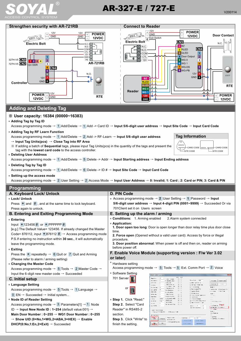
Strengthen security with AR-721RB
Electric Bolt Electric Bolt
Connect to Reader
Access programming mode → Add/Delete → Add -> RF-Learn → Input 5/6-digit user address
→ Input Tag Units(pcs) → Close Tag into RF Area※ If adding a batch of Sequential tags, please input Tag Units(pcs) in the quantity of the tags and present the tag with the lowest card code to the access controller.
1 2Adding Tag by RF Learn Function
Tag Information
SITE CODE
CARD CODE
SITE CODE
CARD CODE
Adding and Deleting Tag※ User capacity: 16384 (00000~16383)
Access programming mode → Add/Delete → Add -> Card ID → Input 5/6-digit user address → Input Site Code → Input Card Code1 1Adding Tag by Tag ID
Access programming mode → Add/Delete → Delete -> Addr → Input Starting address → Input Ending address1 5Deleting User Address
Access programming mode → User Setting → Access Mode → Input User Address → 0: Invalid; 1: Card ; 2: Card or PIN; 3: Card & PIN2 2Setting up the access modeAccess programming mode → Add/Delete → Delete -> ID # → Input Site Code → Input Card Code1 6Deleting Tag by Tag ID
D. PIN Code
C. Initial setup
Access programming mode → User Setting → Password → Input 5/6-digit user address → Input 4-digit PIN (0001~9999) → Succeeded Or via 701Client set it on Users screen
2 1
Node ID of Reader SettingAccess programming mode → Parameters[1] → Node ID → Input New Node ID : 1~254 (default value:001) →
Main Door Number : 0~255 → WG1 Door Number : 0~255 → Show UID (0=No,1=WG,2=ABA,3=HEX) → Enable DHCP(0:No,1:En,2=Exit) → Succeeded
3 1
Language SettingAccess programming mode → Tools → Language → 0 EN → Succeeded → Initial system...
5 1
F. Enable Voice Module (supporting version : F/w Ver 3.02 or later)
Software Setting701 Server
or
Programming
B. Entering and Exiting Programming Mode
Changing the Master CodeAccess programming mode → Tools → Master Code →
Input the 6-digit new master code → Succeeded5 2
A. Keyboard Lock/ UnlockLock/ UnlockPress and , and at the same time to lock keyboard. Press again to unlock.
EnteringInput 123456 or PPPPPP[e.g.] The Default Value= 123456. If already changed the Master Code= 876112, input 876112 → Access programming modeP.S.If entering no instruction within 30 sec., it will automatically leave the programming mode.ExitingPress the repeatedly → Quit or Quit and Arming (Please refer to alarm / arming setting)
6 7
E. Setting up the alarm / armingConditions: 1. Arming enabled 2.Alarm system connectedApplication:1. Door open too long: Door is open longer than door relay time plus door close time.2. Force open (Opened without a valid user card): Access by force or illegal procedure.3. Door position abnormal: When power is off and then on, reader on arming before power off.
Step 1. Click "Read." Step 2. Select "Card Reader" in RS485-2 section. Step 3. Click "Write" to finish the setting.
Hardware settingAccess programming mode → Tools → Ext. Comm Port → Voice5 5 2

V200114
RESET
LCD Access Controller
Enable/Disable the arming status:Standby Mode
Access Programming mode
Card only Card or PIN Card and PINOpen the doorPresent the tag to reader → Input 4 digits arming PWD →
Input user address → Input 4 digits individual PWD → →
Input 4 digits arming PWD →
Present the tag to reader → Input 4 digits individual PWD → →
Input 4 digits arming PWD →
Enable: Access programming mode → Quit & Arming7 Disable: Access programming mode → Quit6
No open the door → Input 4 digits arming PWD
→ Present the tag to reader
E. Setting up the alarm / arming
Restoring Factory SettingsReset all device parameters and user card data
Reset IP Setting:When the device's power is on, press the【RESET】button the main board untill the ERR (Red) LED of screen lights up. (Reference to picture)
※ After operation as above, you will hear the long reminder sound,and wait until the sound disappear then reset the power of the controller,the device will restore factory setting.
Manu Tree5. Tools
1. Language2. Master Code3. Master Range4. Terminal Port5. Ext.Comm Port6. Open Time Zone7. Informations8. Clock Setting9. Daily Alarm0. UART PortA. Event Logs
6. Quit
7. Quit & Arming
4. Parameters[2]1. Auto Relock2. Egress(R.T.E)3. Miscellaneous4. Force Open5. Close & Stop6. Anti-pass-back7. Duress Code8. Password Mode9. Factory Reset
3. Parameters[1]1. Node ID2. OnOff OpenZone3. Door Relay Tm4. Door Close Tm5. Alarm Relay Tm6. Alarm Delay Tm7. Arming Delay Tm8. Arming PWD9. PIN&UID format
2. User Setting1. Password2. Access Mode3. Extend Options4. Single Floor5. Multi Floor
1. Add/ Delete1. Add > Card ID2. Add > RF Learn3. Suspend > Address4. Suspend > ID #5. Delete > Address6. Delete > ID #7. Recover > Address8. Recover > ID #9. Antipass Group
Reset all device parameters and user card data:Access programming mode → Parameters2 → Factory Reset →0 : System Param ; 1 : User Setting ; 2 : System & User
94
IP Setting
Log-in User PasswordWhen you choose the "Networking Setting" or "User Password" at first.Log-in window will pop out and please input※ At the Factory DefaultUser name: SuperAdmPassword: 721568
Open your Web Browser and input factory default IP address: http://192.168.1.127
Networking Setting
You will find initial IP Address 192.168.1.127 and check MAC Address is the same as sticker on Ethernet Module device. Please revise IP address you want, and then click “Update” button. After updating the IP, please re-connect the Web Browser by new IP address.
User Password
The password composes of 10 characters at most, it can be either A~Z or 0~9.
Change the log-in password to lock the IP setting of Ethernet Module.
If the IP address of AR-327-E / 727-E has changed We must enter the new IP address.