acceptance control asphalt layers
TRANSCRIPT

63
Materials Manual
Western Cape : Provincial Administration
Department of Transport and Public WorksRoads Infrastructure Branch
Acceptance Control Asphalt Layers
BaseSubbaseSelected
Surfacing
Subgrade
Volume 2 Chapter 17 Revision 0

Materials Manual First Edition
Chapter 17 Acceptance Control
Asphalt Layers
Western Cape Provincial Administration Department of Transport and Public Works Roads Infrastructure Branch

Western Cape Provincial Administration © 2008 by the Western Cape Provincial Administration. All right reserved First Edition revision 0 published 2008. Printed in the Republic of South Africa
SET: ISBN 0-620-29823-5 CHAPTER: ISBN 1-920158-18-9

WCPA Department of Transport and Public Works Materials Manual Volume 2 Chapter 17
TABLE OF CONTENTS
ACCEPTANCE CONTROL: ASPHALT LAYERS
Contents page 17-
INTRODUCTION ..................................................................................................1
SOURCE ...........................................................................................................2 Introduction ...................................................................................................................................2 Sampling Plan ...............................................................................................................................2 Tests..............................................................................................................................................2 Time Schedule To Obtain Acceptance .........................................................................................3 Applicable Forms ..........................................................................................................................3 Assessment...................................................................................................................................4
Coarse Aggregate ............................................................................................................................ 4 Fine Aggregate................................................................................................................................. 4 Filler.................................................................................................................................................. 4 Bituminous Binder ............................................................................................................................ 4
DESIGN MIX ......................................................................................................5 Introduction ...................................................................................................................................5 Tests..............................................................................................................................................5 Time Schedule To Obtain Acceptance .........................................................................................5 Applicable Forms ..........................................................................................................................5 Assessment...................................................................................................................................5 Approval Of Design .......................................................................................................................6
TRIAL SECTION .................................................................................................7 Introduction ...................................................................................................................................7 Sampling Plan ...............................................................................................................................7 Tests..............................................................................................................................................8
Laboratory ........................................................................................................................................ 8 Field.................................................................................................................................................. 8
Time Schedule To Obtain Acceptance .........................................................................................9 Applicable Forms ..........................................................................................................................9 Assessment...................................................................................................................................9
Grading............................................................................................................................................. 9 Compaction .................................................................................................................................... 10 Other Properties ............................................................................................................................. 10
Approval Of Trial Section ............................................................................................................10
CONSTRUCTION LOTS ......................................................................................12 Introduction .................................................................................................................................13 Sampling Plan .............................................................................................................................13 Tests............................................................................................................................................13
Supply Control Of Mix..................................................................................................................... 13 Asphalt Mix..................................................................................................................................... 14 Layer Thickness ............................................................................................................................. 14
Time Schedule To Obtain Acceptance .......................................................................................14 Applicable Forms ........................................................................................................................14 Assessment.................................................................................................................................15
Compaction .................................................................................................................................... 15 Binder Content ............................................................................................................................... 19 Voids .............................................................................................................................................. 19 Grading........................................................................................................................................... 20 Shape............................................................................................................................................. 20 Stability and Flow ........................................................................................................................... 20 Dynamic Creep and ITS ................................................................................................................. 20
17 Acceptance Control: Asphalt Layers 20 October, 2008 page 17-i

WCPA Department of Transport and Public Works Materials Manual Volume 2 Chapter 17
General .......................................................................................................................................20 Compaction .................................................................................................................................... 21 Slippage ......................................................................................................................................... 21 Early Trafficking.............................................................................................................................. 21
Submission of Acceptance Control Forms..................................................................................22 As-Built Data Sheets ...................................................................................................................22
FIGURES Figure 17-1: Layout of the Materials Manual....................................................................................................1 Figure 17-2: Example of design form for verification for asphalt layers .........................................................11 Figure 17-3: Example of design form for verification for asphalt layers .........................................................12 Figure 17-4: Example of completed form E-ASS-ACB1-E .............................................................................17 Figure 17-5: Example of completed form E-ASS-ACA1-E .............................................................................18
TABLES Table 17-1: Example of Typical Compaction Window Reductions for Thin Mats ...........................................21
TABLE OF CONTENTS
page 17-ii 20 October, 2008 17 Acceptance Control: Asphalt Layers

WCPA Department of Transport and Public Works Materials Manual Volume 2 Chapter 17
INTRODUCTION
ACCEPTANCE CONTROL: ASPHALT LAYERS
INTRODUCTION This chapter gives the background required to adequately apply the acceptance control proc-ess for asphalt layers, as well as identifying some problems, and the means to address the problems to provide an acceptable product.
This chapter’s part in the overall layout of the Material’s Manual is shown in Figure 17-1.
The Western Cape Provincial Administration has over the years constructed the bulk of its
heavily trafficked road network using deep granular flexible pavements. The accelerating growth of heavy axles on the network has led to more frequent use of asphalt layers for
• asphalt surfacing, and • asphalt base, where larger aggregate
sizes have been introduced in mixes, commonly known as large aggregate mixes for bases (LAMBS).
Chapter 15 CHEMICALLY
TREATED LAYERS
INPUTS ACTIVITIES
Chapter 8 QUALITY ASSURANCE
ACCEPTANCE CONTROL7 Construction equipment
control
Chapter 13SELECTED LAYERS
Chapter 14SUBBASE LAYERS SEALS
Chapter 19 GRAVEL WEARING
COURSE
Chapter 20 CONCRETE
Chapter 9BASIC CONCEPTS
Chapter 10ROADBED
Chapter 12FILL
INPUTS ACTIVITIES
QUALITY ASSURANCE
ACCEPTANCE CONTROL7 Construction equipment
control
Chapter 13SELECTED LAYERS
Chapter 14SUBBASE LAYERS
Chapter 18
Chapter 19 GRAVEL WEARING
COURSE
Chapter 20 CONCRETE
Chapter 9BASIC CONCEPTS
Chapter 10ROADBED
Chapter 12FILL
Chapter 11 STOCKPILED
MATERIAL
Chapter 16 BASE LAYERS
Chapter 17 ASPHALT LAYERS
Figure 17-1: Layout of the Materials Manual
17 Acceptance Control: Asphalt Layers 20 October, 2008 page 17-1

WCPA Department of Transport and Public Works Materials Manual Volume 2 Chapter 17
SOURCE
INTRODUCTION
SOURCE
Asphalt is usually purchased from a commer-cial source. The aggregates used to manufac-ture the asphalt are delivered to the asphalt plant and control is exercised through sam-pling from the hot bins or the aggregate stock-piles.
For fixed commercial plants and new or mo-bile plants quality control of the aggregates is exercised through
• sampling of the stockpiles at the crusher site, cold feed and/or hot bins of the as-phalt plant, especially in the case of as-phalt batch plants,
• sampling the binder quality and testing of specific properties.
In the case of new aggregate sources for pro-jects remote from a commercial asphalt plant, the new sources shall be adequately explored and on completion, rehabilitated as outlined in Chapter 5, “Materials Investigations and Re-porting”.
The proposed site and rehabilitation plan for borrow pits shall be approved by the Regional Director, Minerals and Energy, in accordance with the procedures outlines in Chapter 5, “Materials Investigation and Reporting”, “En-vironmental Assessment Report”, and “Inspec-tion and Approvals” prior to proceeding with any mining activities. Guidelines for sourcing material and the developing, operating and closing of borrow pits/quarries is covered in the Department’s Operations Manual1.
The conformance control requirements of ma-terials and mixes shall be in accordance with Chapter 8, “Quality Assurance”, under the fol-lowing sections:
“Asphalt Bases” and table for “Compo-nent conformance control - asphalt base”
1. “Operations Manual, Manual for the Identification, de-
velopment, operation and closure of gravel material sources”, Western Cape Provincial Administration, De-partment of Transport, Cape Town, September 2006.
“Surfacing - Hot-mix Asphalt, Unmodi-fied Bitumen Binder” and table for “Com-ponent conformance control - asphalt surfacing - unmodified bitumen binder”
“Surfacing - Hot-mix Asphalt, Modified Bitumen Binder” and table for “Component conformance control - asphalt surfacing - bitumen-rubber asphalt”
SAMPLING PLAN The sampling plans for aggregates, bitumen and rubber are provided in Chapter 4, “Field Sampling Methods”, under the headings listed below:
• “Sampling Plan, Processed Materials”
• “Sampling of Natural Materials”
• “Sampling of Bituminous Binders”
• “Sampling of Processed Materials (Un-treated)” and
• “Sampling of other commodities”
Further information can be obtained from Chapter 11, “Stockpiled Material”.
TESTS Refer to Chapter 8, “Quality Assurance” for tests to be carried out on the materials and type of mixes as indicated under “Component Con-formance Control” for
• “Base, Asphalt Bases” and table for “Component Conformance Control - asphalt base”,
• “Surfacing - Hot-mix Asphalt, Un-modified Bitumen Binder” and table for “Component Conformance Control - asphalt surfacing - unmodified bitu-men binder”, and
• “Surfacing - Hot-mix Asphalt, Modi-fied Bitumen Binder” and table for “Component Conformance Control - asphalt surfacing - bitumen-rubber as-phalt”.
page 17-2 20 October, 2008 17 Acceptance Control: Asphalt Layers

WCPA Department of Transport and Public Works Materials Manual Volume 2 Chapter 17
Refer to SABITA Manual No. 3, “Test meth-ods for bitumen-rubber”2.
The properties measured in this phase of qual-ity control are normally the following:
Aggregate (coarse and fine)
• Grading
SOURCE
• Strength (hardness) by virtue of its geo-logical origin
• Durability (resistance to environmental weathering)
• Shape and texture (flakiness, elongation, crushed faces)
• Absorption (water and type binder) • Abrasive resistance (polishing under traf-
fic) • Atterberg Limits (active clay) • Binder adhesion (stripping)
Filler
• Type (active, e.g., lime, cement; non-active, e.g., cyclone dust, etc.)
• Grading • Density in toluene for fineness
Binder (conventional or modified)
• Type (normally unmodified bitumen) • Grade viscosity and penetration • Softening Point (ring and ball) • Ductility • Composition (saturates, aromatics, res-
ins, asphaltences) • Ageing of bitumen before and after use
(Rolling thin film oven test [RTFOT])
Modifier
• Type and grade (rubber, polymer) • Grading of crumbed rubber • Resilience of crumbed rubber • Extender oil in the case of crumbed rub-
ber
Blend (Bitumen rubber binder)
• Softening point • Flow • Viscosity
2. “Test methods for bitumen-rubber”. SABITA, Man-
ual 3, Cape Town, 1992.
• Resilience • Compression-recovery • Ductility
TIME SCHEDULE TO OBTAIN ACCEPTANCE
The time schedule to obtain acceptance for the product is governed by the time to obtain the required samples and the duration of specific tests. A schedule is outlined in Chapter 3, “Commentary on Test Methods, Time Sched-ule for Duration of Testing”.
APPLICABLE FORMS
STAGE FORM CODE DESCRIPTION
Sampling S-SOU-GRA-E Field samples of Material for Pave-ment Layers - Borrow Pits
S-SOU-SUR-E Field samples of material for surfacing
Testing T-DAT-BRB-E Bitumen-rubber binder - spray/mixing grade component and blending control
T-DAT-SUR1-E Test data: aggregate for bituminous sur-facing and layers
Evaluation E-ASS-ACB1-E Acceptance Control – Constructed Base - Continuously Graded Asphalt
E-ASS-ACA1E Acceptance Control – Constructed Wear-ing Course - Con-tinuously Graded Asphalt
E-ASS-ACA2-E Acceptance Control – Constructed Wear-ing Course - Semi Gap Graded Asphalt
E-ASS-ACA3-E Acceptance Control – Constructed Wear-ing Course – Porous (Open Graded) As-phalt
E-ASS-ACA4-E Acceptance Control – Constructed Wear-ing Course – Stone Mastic Asphalt
STAGE FORM CODE DESCRIPTION
17 Acceptance Control: Asphalt Layers 20 October, 2008 page 17-3

WCPA Department of Transport and Public Works Materials Manual Volume 2 Chapter 17
SOURCE
E-ASS-ACF-E Acceptance Control – Constructed Fric-tion Course – Thin and Ultra Thin As-phalt
ASSESSMENT
COARSE AGGREGATE The coarse aggregate in an asphalt mix should be uniform in quality, especially as regards grading, free from deleterious matter, weath-ered and disintegrating particles. The particles should ideally be cubical and shall conform to the flakiness index criterion. The texture and shape will also influence the stability of the mixture, and therefore, an angular shape is pre-ferred to rounded and/or elongated particles. In the case of natural gravel, only the clean, hard material, preferably more than 40 mm in di-ameter, which is free from any organic matter and clay lumps (which could make it more sus-ceptible to binder stripping), should be crushed. The crushed particles must conform to the criterion for crushed faces.
Aggregates with a high binder or water absorp-tion (>1,0 percent) should be carefully evalu-ated since such material can result in the long term drying out of mixtures with correspond-ing poor durability, shrinkage, cracking and even disintegration.
FINE AGGREGATE The shape and texture of particles significantly affects the workability of the mix as well as the resistance to deformation.
The sand equivalent value (which is computed as a ratio of the sand to clay height readings, using a flocculating test procedure), shall be at least 50 as per COLTO Standard Specifica-tions3, Clause 4202 (b) (vi).
The binder and water absorption greater than 1,5 percent should be evaluated carefully to avoid long term drying out, i.e., poor durabil-ity.
FILLER Active filler shall consist of milled blast fur-nace slag, hydrated lime, ordinary portland cement, portland blast furnace cement, fly-ash, or a mixture of any of the above materials as specified or determined during design verifica-tion stages. Acceptance will be based on ap-propriate certification of the product offered, or on appropriate tests being performed to ver-ify such certification.
BITUMINOUS BINDER The bituminous binder must comply with stan-dards given in Chapter 2, “Materials Stan-dards”, COLTO Standard Specifications3 and the project specifications.
For bitumen-rubber blends, the rubber crumb shall comply with the requirements of COLTO Standard Specifications3 (Section 4200, Clause 4202 (a) (2) and Table 4202/1). It should be noted that the natural rubber content of different sources may differ, thus requiring the addition of different percentages of rubber crumb to produce an equivalent blend.
3.Standard Specification for Road and Bridge Works for
State Road Authorities, COLTO, Pretoria, 1998
page 17-4 20 October, 2008 17 Acceptance Control: Asphalt Layers

WCPA Department of Transport and Public Works Materials Manual Volume 2 Chapter 17
DESIGN MIX
INTRODUCTION
SOURCE
The laboratory design method adopted can be either according to Marshall or, in the case of LAMBS design, according to Hugo (Modified Kentucky) procedure4. It is a means of select-ing and proportioning materials, within the limits of the project specifications, to obtain a mix with the desired qualities and properties by determining the most economical blend. This is done by:
• optimising the grading of the coarse aggregate, fine aggregate and fillers, and
• the addition of a suitable binder in suf-ficient quantities.
The method should yield a mix having the fol-lowing properties:
• thorough coating of the aggregate parti-cles and bonding them together to ensure a durable pavement layer under desirable compaction;
• sufficient mix stability and resistance to flow, to satisfy the long term service re-quirements and demands, especially un-der heavy traffic, without distortion and displacement; and
• for continuously graded mixes, sufficient unconnected voids in the mix to prevent flushing and permeability
The laboratory compacted mix must • provide a reservoir of space for the ex-
pansion of binder even after additional compaction due to traffic, bleeding, or loss of resistance to plastic deformation, but
• limit the space to keep harmful air and/or moisture out, and
• have sufficient workability to permit ef-ficient placing of the mix without the segregation of aggregate, especially in the case of coarse graded mixes.
4. “LAMBS - The design and use of large aggregate
mixes for bases”. SABITA, Manual 13, Cape Town, 1993.
In the case of high performance layers the Bayley method should also be consulted.
TESTS Refer to Chapter 8, “Quality Assurance” for the appropriate tests to be carried out as indi-cated under Design Verification for the follow-ing layers and types of mixes:
“Basecourse, Asphalt Base” and table for “Design Verification (laboratory) - Asphalt Base”
“Surfacing - Hot-Mix Asphalt, Unmodi-fied Bitumen Binder” and table for “Design verification (laboratory) - asphalt surfacing - unmodified binder”
“Surfacing - Hot-Mix Asphalt, Modified Bitumen Binder” and table for “Design verifi-cation (laboratory) - bitumen-rubber asphalt”
TIME SCHEDULE TO OBTAIN ACCEPTANCE
The duration of the relevant tests can be as-sessed using Chapter 3, “Commentary on test methods, Time schedule for duration of test”.
APPLICABLE FORMS
STAGE FORM CODE DESCRIPTION
Testing T-BEN-ASP-E Test Data: As Built Test Results Asphalt mixes
Evaluation FORM D3
(TMH 10) Asphalt Mix Design
ASSESSMENT The use of modified binders, such as bitumen-rubber blends, should be a well controlled process to ensure the required properties. For further details of the blending of the various constituents, i.e., bitumen, crumbed rubber and extender oil, refer to Chapter 6, “Materials Se-lection, Constraints and Design Procedures,
17 Acceptance Control: Asphalt Layers 20 October, 2008 page 17-5

WCPA Department of Transport and Public Works Materials Manual Volume 2 Chapter 17
Bitumen-Rubber Asphalt”. Charts showing the resilience, flow, softening point (ring and ball) and viscosity with time should be obtained and submitted during the Mix Design stage.
SOURCE
APPROVAL OF DESIGN For the approval of the proposed design the following form must be submitted to the Mate-rials Engineer at the earliest stage, well before the trial sections commence with an accompa-nying letter recommending the design parame-ters. The form is the same as that to be used later for the trial section, but has the specifica-tion for the proposed design inserted.
In addition for asphalt using a non-homogeneous modified binder (bitumen-rubber) the requirements of COLTO3 (Sec-tion 4200, Clause 4202 (a) (4) and /or such other Project Specifications shall be complied with. The information, which includes a
method statement, details of the proposed plant, component details, blending / reaction
temperature and reaction time, should all be substantiated by behaviour curves for the re-quired properties` and be submitted at least two weeks prior to the commencement of the blending operation.
FORM CODE APPLICATION
E-DET-ASP-E Design Verification – Trial Sec-tion – Asphalt Layers
A copy of the letter and also of the forms to the Manager: Pavement Technology, Materials Testing Laboratory, Cape Town. See Chap-ter 1, “Management Procedures For Monitor-ing And Control, Proposed Designs and Trial Sections”.
page 17-6 20 October, 2008 17 Acceptance Control: Asphalt Layers
WCPA Department of Transport and Public Works Materials Manual Volume 2 Chapter 17
TRIAL SECTION INTRODUCTION
Once the source materials and laboratory de-sign has been approved, it is necessary to time-ously assess and verify construction procedures and processes (e.g., plant mixing, stockpiling procedures, compaction tech-niques, etc.) applied to satisfy the criteria out-lined in Chapter 2, “Materials Standards, Hot-Mix Base”, “Surfacing, Conventional Hot-Mix Asphalt”, “Surfacing, Bitumen-Rubber As-phalt”, and/or COLTO Standard Specifica-tions3, before proceeding with full production.
The constraints that have been imposed are based on extensive research, constructability considerations and ultimately verified with the Heavy Vehicle Simulator. Unless substantive historic data is available verifying all relevant parameters, a length of asphalt base or surfac-ing shall be constructed as a trial section:
TRIA
• at the start of any asphalt base or sur-facing, or
L SE
• on the introduction of asphalt base or surfacing from a new source, or
CTIO
• when crusher modification and/or other processes need to be introduced to at-tain the required grading, or
N
• when compaction problems are experi-enced with a previous trial section.
After a mix design is approved, a trial mix should be run through the asphalt plant and tested for conformance, before a trial section is paved with the material
The construction of a trial section provides the opportunity to
• calibrate the dynamic properties of the mix design;
• verify the laboratory target grading be-fore and after placement by the paver in order to agree to a target grading for the construction lots;
• assess the variability of the grading;
• verify the adequacy of the crushing ar-rangement, stockpiling techniques and plant capability, or to make appropriate corrections to the production plant, or where the situation warrants a labora-tory re-design and re-evaluation;
• agree on binder content and character-istics of modified binder where appli-cable;
• assess constructability issues such as the paver performance (being a func-tion of settings/adjustments such as au-ger box/ auger height, automatic level control devices; maintenance manage-ment of components especially those subject to a high rate of wear such as tamper bars, screed plates etc.); and
• do a compaction study in order to agree on
- the use of the most suitable type of roller, or combination of rollers,
- the minimal roller passes,
- rolling pattern for each roller to ob-tain the maximum or desired com-paction at the most desirable temperature at the minimal com-paction cost, and
- compaction window temperatures
SAMPLING PLAN The sampling requirements for a trial section are given in Chapter 4, “Sampling Methods, Asphalt Pavement Layers”, and/or project specifications, and covers the position of test points for core samples to be tested in the labo-ratory.
The sampling plan and procedures to obtain field samples of the mix before compaction are given in Chapter 4, “Sampling Methods”, and respectively “Sampling Plan, Asphalt Pave-ment Layers” and “Sampling of Pavement Layers, Asphalt Layers”, or in the project specification. The following issues are cov-ered:
17 Acceptance Control: Asphalt Layers 20 October, 2008 page 17-7

WCPA Department of Transport and Public Works Materials Manual Volume 2 Chapter 17
Location of such a trial section
Size of trial section (usually 150 tons minimum but preferably 200 tons)
The number of samples
Position of test points
Procedure for obtaining a field sample of the mix
Procedure to obtain specimens for density determination
A minimum of six duplicate samples (a mini-mum of 10 kg per sample) of the mix and six layer specimens (core or cut specimens) may be required by the Manager: Pavement Tech-nology, Materials Testing Laboratory, Cape Town.
TESTS
TRIAL SECTION
Refer to Chapter 8, “Quality Assurance” for the appropriate tests to be carried out, as indi-cated under Design Verification (trial section), for the following layers and types of mixes:
“Basecourse, Asphalt Base” and table for “Design Verification (trial section) - Asphalt Base”
“Surfacing - Hot-Mix Asphalt, Unmodi-fied Bitumen Binder” and table for “Design verification (trial section) - asphalt surfacing - unmodified binder”
“Surfacing - Hot-Mix Asphalt, Modified Bitumen Binder” and table for “Design verifi-cation (trial section) - bitumen-rubber asphalt”
LABORATORY
MIXTURE Samples of the asphalt mix before compaction shall be taken for the following laboratory tests:
Binder content
Grading, flakiness and fractured faces (only fractions equal to or greater than 6,7 mm)
Marshall or Hugo (Modified Kentucky) properties such as maximum theoretical den-
sity (Rice) stability, flow, dynamic creep, indi-rect tensile strength, VIM, VMA, VFB, immersion index, etc., determined on labora-tory compacted specimens.
Cantabro abrasion loss (only porous as-phalt).
MODIFIED BINDER The following tests shall be carried out:
Ball penetration and resilience
Compression-recovery
Flow
Dynamic viscosity
Softening Point (ring and ball)
Determination of the digested rubber for correction factor to adjust to actual binder con-tent
FIELD
MIXTURE The temperature of mixture
• at the plant, • in the load truck arriving at site, • before unloading in hopper, either in
truck or hopper, and • after placement by paver but prior to
compaction
shall be recorded on the Form R-LOG-ASP1-E with all other information, such as samples taken, weather conditions, etc.
In addition, for bitumen-rubber, the tempera-ture of the blend shall be carefully controlled and monitored during blending operations, with random checking by the Engineer.
LAYER For continuously graded mixes, the compac-tion operation can be monitored by means of a nuclear density apparatus, but it must be cali-brated against cores. For acceptance control compaction shall be measured on cores.
Core samples shall be obtained prior to open-ing the layer to traffic and should be cut at low
page 17-8 20 October, 2008 17 Acceptance Control: Asphalt Layers
WCPA Department of Transport and Public Works Materials Manual Volume 2 Chapter 17
surface temperatures. For a layer thickness greater than 35 mm, and a normal mean aggre-gate size (NMAS) up to 26,5 mm a core sam-ple with a diameter of 100 mm is suitable. For NMAS > 26,5 mm diametric cores are prefer-able.
Marvil permeability tests shall be done prior to coring at each test point.
The following tests shall be carried out on the cores:
TRIAL SECTION
Bulk relative density (all cores)
Dynamic creep (6 cores minimum)
Resilient modulus (6 cores minimum)
Indirect Tensile Stress (6 cores mini-mum),being the same cores as used for the de-termination of the resilient modulus
Binder determination as well as grading if so directed (normally only required when minimum dynamic properties not achieved)
These tests will normally apply to all proposed new designs prior to proceeding with any pro-duction runs. For proven designs using con-ventional binders, the Engineer may relax this requirement subject to still having the cores extracted and tested by an approved laboratory if so required by the Materials Engineer.
These tests will be performed on a random ba-sis as the project progresses, with a higher fre-quency of testing being applicable to new designs. In addition, the frequency of testing shall relate to risk of environmental factors (temperature levels, heavy axle intensity, steep gradients/ intersection areas, grading and ag-gregate shape variability, and binder variabil-ity).
TIME SCHEDULE TO OBTAIN ACCEPTANCE
The duration of the relevant tests can be as-sessed using Chapter 3, “Commentary on test methods, Time Schedule For Duration Of Test-ing”.
Duplicate samples will be required by the Con-trol Laboratory (refer to Chapter 1, “Manage-
ment Procedures for Monitoring and Control, Administrative Procedures, Correspondence, Proposed Design And Trial Sections”), which could delay the final approval of the various parameters/criteria proposed for construction control.
Also note the time constraints in Section 8000 of the COLTO Standard Specifications for Road and Bridge Works3.
APPLICABLE FORMS
STAGE FORM CODE DESCRIPTION
Sampling S-SOU-SUR-E Field samples of mate-rial for surfacing
Testing T-DAT-BRB-E
T-DAT-ASP-E
Bitumen-rubber binder - spray/mixing grade component and blend-ing control Test Data: Asphalt Lay-ers
T-DAT-SUR1-E
T-BEN-PERI-E
Test data: aggregate for asphalt surfacing or layers Test Data: Permeability Water: Method Marvil
Evaluation E-ASS-MAR-E
E-DET-ASP-E
Field Test: Water per-meability Marvil Design Verification - Trial Section - Asphalt Layers
ASSESSMENT
GRADING The procedure to assess the grading obtained from a trial section in order to arrive at a target for construction lots is as follows:
Record the values of percentage passing each sieve obtained for each sample on Form E-DET-ASP-E and compare the mean grading with the laboratory design target grading lim-its. See example Figure 17-2 on page 17-11 for asphalt bases and wearing courses and Fig-ure 17-3 on page 17-12 for friction courses
Plot the grading envelope. This is the mean value obtained for each sieve plus twice the standard deviation (2Sn) on either side of the plotted mean value. On the same figure,
17 Acceptance Control: Asphalt Layers 20 October, 2008 page 17-9

WCPA Department of Transport and Public Works Materials Manual Volume 2 Chapter 17
plot the required asphalt grading envelope. It should be critically assessed with respect to the asphalt mix specifications and requirements for properties such as stability, creep etc.
APPROVAL OF TRIAL SECTION
For approval of the trial section and mix de-sign the following forms must be submitted to the Materials Engineer at the earliest stage, long before the construction sections com-mence, with an accompanying letter stating the motivation for changing the approved design.
COMPACTION The typical standard deviations for compaction are between 1 and 2 percent. See Chapter 9, “Acceptance Control: Basic Concepts”, for more details. The specified minimum compac-tion, expressed as a percentage of the maxi-mum theoretical density (Rice’s Method), is given in Chapter 2, “Materials Standards”. The mean value of the maximum theoretical den-sity shall be used for calculating compaction.
FORM CODE APPLICATION
E-DET-ASP-E Design Verification - Trial Sec-tion - Asphalt Layers (base & wearing courses)
E-DET-AFC-E Design Verification – Trial Sec-tion – Friction Courses
E-ASS-ACA1-E Acceptance Control - Asphalt Surfacing - Continuously Graded
E-ASS-ACA2-E Acceptance Control - Asphalt Surfacing - Semi-Gap Graded
E-ASS-ACA3-E Acceptance Control - Asphalt Surfacing - Open Graded
E-ASS-ACF-E Acceptance Control - Friction Courses (Thin and Ultra Thin)
E-ASS-ACB1-E Acceptance Control - Asphalt Base - Continuously Graded
Typically asphalt base placed in a 55 to 75 mm single compacted layer, using double-drum vibratory roller and a 25 ton pneumatic tyre roller (tyre pressure 7 to 8 bars), should be ca-pable of obtaining compaction in the range of 93 to 97 percent (Maximum Theoretical Rela-tive Density) when Marshall Vims are of the order of 4,0 to 4,5 percent.
TRIAL For small projects it may sometimes not be ap-
propriate to assess the proper use of compac-tion equipment in order to arrive at a meaningful type of roller and roller pattern. In this case, the mix properties and/or proven mixtures may give an indication of construc-tability.
SE A copy of the letter and the forms shall be sent
to the Head: Materials Support Services, Cape Town. See Chapter 1, “Management Proce-dures For Monitoring And Control, Proposed Designs and Trial Sections”.
CTION
The outcome of the tests done by the Manager: Pavement Technology, Materials Testing Laboratory will verify the proposed target set-tings for acceptance, or adjustment for an addi-tional trial section.
OTHER PROPERTIES The shape of the aggregate, stability, flow, dy-namic creep, etc., should be assessed with re-gard to the approved design.
page 17-10 20 October, 2008 17 Acceptance Control: Asphalt Layers

WCPA Roads & Traffic Administration Branch Materials Manual Volume 2 Chapter 17
CONSTRUCTION LOTS
Figure 17-2: Example of design form for verification for asphalt layers
17 Acceptance Control: Asphalt Layers 20 October, 2008 page 17-11

WCPA Department of Transport and Public Works Materials Manual Volume 2 Chapter 17
CONSTRUCTION LOTS
Figure 17-3: Example of design form for verification for asphalt layers
page 17-12 20 October, 2008 17 Acceptance Control: Asphalt Layers

WCPA Roads & Traffic Administration Branch Materials Manual Volume 2 Chapter 17
CONSTRUCTION LOTS INTRODUCTION
The quality of the asphalt layer is judged by means of construction lots. The construction lots shall satisfy the criteria outlined in Chap-ter 2, “Materials Standards”, and is usually based on minimum tons or on a day’s produc-tion
• “Hot Mix Asphalt Base”, or • “Surfacing, Conventional Hot-Mix As-
phalt”, or
CONSTRUCTION LOTS
• “Surfacing, Bitumen-Rubber Asphalt”, or
• the appropriate project specifications.
The test section representing the construction lot shall be visually homogeneous. Any iso-lated, non-homogeneous areas (e.g., coarse patches) must be excluded from the test sec-tion and treated separately.
The use of a statistical judgement plan appli-cable to certain parameters, such as degree of compaction, binder content, voids-in-mix and grading in certain cases, involves a random sampling procedure. This approach provides for
• the appropriate corrections to be made at the plant to ensure that the mix proper-ties will not violate the target limits set;
• the verification of the target limits to en-sure that engineering properties required are being met; and
• a low level of risk to the client authority of accepting a poor quality product, or a low, fixed risk to the contractor of rejec-tion of a good quality product.
SAMPLING PLAN The sampling plan and procedures to obtain field samples of the mix before compaction are given in Chapter 4, “Sampling Methods”, and respectively “Sampling Plan, Asphalt Pave-ment Layers” and “Sampling of Pavement Layers, Asphalt Layers”, “Sampling of Bitu-minous Treated Materials”, or in the project
specification. The following issues are cov-ered:
Size of construction lot
The number of samples
Position of test points
Procedure for obtaining a field sample of the mix
Procedure to obtain specimens for density
TESTS The requirements are given in Chapter 8, “Quality Assurance, Construction Layer Con-trol”, tables for the appropriate asphalt mix:
Asphalt base
Asphalt Surfacing - unmodified bitumen binder
Asphalt Surfacing - modified binder
SUPPLY CONTROL OF MIX The Form R-LOG-ASP1-E shall be used to record the following:
The particulars of truck loads
Time of arrival at site
Time of off-loading into hopper
Section covered by the specific load
Temperature of
• the truck load at site (ensure that a tarpaulin cover and not hessian is be-ing used to cover body of truck in or-der to maintain supply temperature level with minimal loss, especially during transport, or while standing at the site of the works),
• the asphalt in paver hopper surface (note tilting of hopper required at regular intervals),
• the layer after placement by paver, but prior to first breakdown compaction,
Particulars of field samples taken with regard to test point position, etc.
17 Acceptance Control: Asphalt Layers 20 October, 2008 page 17-13

WCPA Department of Transport and Public Works Materials Manual Volume 2 Chapter 17
These particulars may be useful in the assess-ment of lots not fully complying with the pro-ject specifications and must be submitted in such cases.
The Form T-DAT-BRD-E must be submitted in the case of modified bitumen-rubber asphalt binder with the appropriate graphs displaying time versus viscosity, etc.
ASPHALT MIX
CONSTRUCTION LOTS
Samples shall be taken at test points for the following laboratory tests:
Binder content Grading Flakiness Fractured faces (where applicable) Bulk relative density of compacted
specimens and maximum theoretical den-sity (Rice density)
Stability and flow (where applicable, not for FC)
Indirect Tensile Strength, (ITS) for high performance mixes.
Gyratory Refusal Densities for high per-formance mixes.
The bitumen-rubber binder is sampled after blending, but before mixing to determine the following properties:
Compression-recovery Softening point (ring and ball) Resilience Flow Dynamic viscosity Homogeneity, i.e., content of saturates,
aromatics, resins and asphaltines
The voids-in-mix and effective relative density of each sample shall be calculated. The effec-tive relative density determines if the binder content and Rice density obtained from each sample is realistic for the type of aggregate blend and binder content specified.
During the compaction of the mix, the roller passes and patterns must be controlled by de-
termining the layer density using a nuclear de-vice.
In the case of lots not fully complying with the project specifications with regard to compac-tion and/or high voids-in-mix, MARVIL per-meability tests shall be mandatory to determine what steps must be taken for payment purposes and/or remedial actions.
LAYER THICKNESS Layer thickness is obtained from cores taken for density determination.
TIME SCHEDULE TO OBTAIN ACCEPTANCE
The duration of the relevant tests can be as-sessed using Chapter 3, “Commentary on test methods, Time Schedule For Duration Of Test”.
APPLICABLE FORMS
STAGE FORM CODE DESCRIPTION
Sampling S-SOU-SUR-E Field samples of material for surfacing
Testing T-DAT-BRB-E Bitumen-rubber binder - spray/mixing grade component and blending control
T-DAT-SUR1-E Test data: aggregate for asphalt surfacing or layers
Evaluation E-ASS-ACA1-E Acceptance Control - Asphalt surfacing - con-tinuously graded -
E-ASS-ACA2-E Acceptance Control - Asphalt surfacing - semi-gap graded
E-ASS-ACA3-E Acceptance Control - Asphalt surfacing - po-rous (open graded) -
E-ASS-ACB1-E Acceptance Control - Asphalt base - continu-ously graded
E-ASS-ACF-E Acceptance Control - Friction Courses (Thin and Ultra Thin)
page 17-14 20 October, 2008 17 Acceptance Control: Asphalt Layers

WCPA Department of Transport and Public Works Materials Manual Volume 2 Chapter 17
ASSESSMENT
CONSTRUCTION LOTS
COMPACTION The assessment of compaction of the layer shall comply with the requirements of a statis-tical judgement plan. The actual variability of the work obtained by the measurements of in situ density from cores shall be used.
The range of standard deviations obtained when statistically assessing compaction is a useful measure of process control applied by the Contractor during the compaction phase, provided that a consistent product is being supplied by the manufacturer (which includes temperature on arrival at paver). Based on past experience a deviation for compaction is typi-cally 1,5. A value of say 2,9, will require fur-ther investigation regarding compaction procedures, such as the extent to which process control is being applied, the control of roller movements (including number of passes), care taken during core extraction procedures etc.
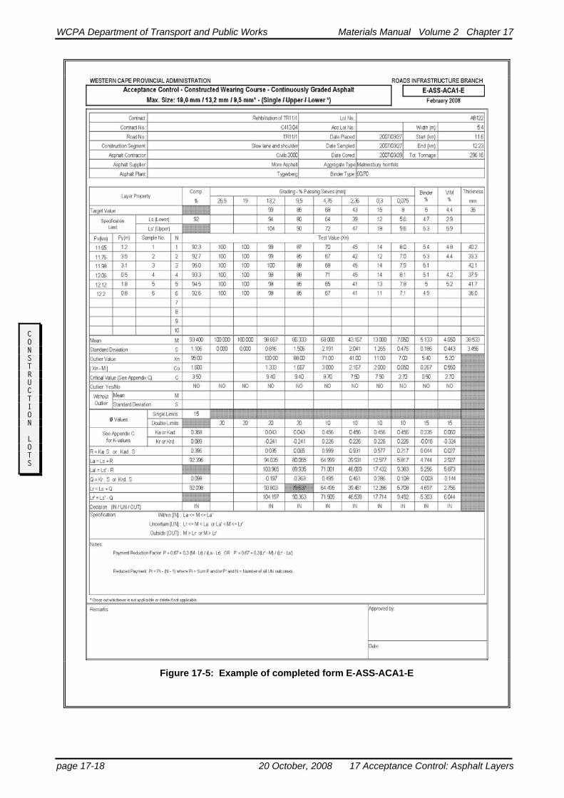
See Figure 17-3 on page 17-17 for Form E-ASS-ACB1-E (Constructed Base-Continuously Graded Asphalt) and Figure 17-4 on page 17-18 Form E-ASS-ACA1-E (Constructed Wear-ing Course - Continuously - Graded Asphalt ). For friction courses form E-ASS-ACF-E is used, which is similar to E-ASS-ACA1-E used for wearing courses, other than the recording of density which is optional.
Outliers are to be dealt with as in Chapter 9, “Acceptance Control: Basic Concepts”, and/or Project specifications. For critical values for asphalt materials see Appendix C, Table of critical values (C0,99;n⋅σ) for outlier test for as-phalt layers.
In the case of an outlier, the kr values for φ=15 percent will be for {n-1} test values. The out-lier shall be further investigated to identify any possible problems with the asphalt layer, etc.
In the case of non-compliance with the specifi-cation, retesting of any test point is not permis-sible. If the decision is in question due to the credibility of the test values, the whole con-struction lot shall be retested with a new set of random test points.
If a test lot is re-tested, the second set of values shall be compared with the first set of values (a minimum of six values for each set) to deter-mine if they belong to the same population. Form E-ASS-COM2-E is used for the com-parison between two sets of values.
The statistical data from the second set of values shall be taken as final.
In the case of non-compliance, the section rep-resented by the lot shall be rejected and the contractor or construction unit shall propose an appropriate remedial action. This remedial ac-tion shall first be approved by the Materials Engineer.
Conditional acceptance may be applied at the sole discretion (see COLTO Standard Specifi-cations3, Clause 8208(a)(i))of the Materials Engineer unless otherwise specifically allowed for in the Project Specifications.
Before considering conditional acceptance for compaction in the case of lots not fully com-plying with the specification, the MARVIL permeability test shall be carried out. If the mean value is:
• ≤3 λ/m2/hr, and single values are <5 λ/m2/hr, ACCEPT but effect pay-ment in accordance with calculated re-duced payment
• >3 λ/m2/hr, use a diluted mineral filled emulsion to waterproof the layer and then RETEST
Reduced payment will normally be the out-come of conditional acceptance.
When considering conditional acceptance for lots with outcomes OUTSIDE the specifica-tions with respect to compaction, (but having all other parameters complying with the speci-fications), no more than 50% payment will be considered. Such reduced payment will al-ways be subject to the Contractor being al-lowed to offer an acceptable alternative, such as:
• milling and reinstating with a totally ac-ceptable product for which he will qualify for 100% payment,
17 Acceptance Control: Asphalt Layers 20 October, 2008 page 17-15

WCPA Department of Transport and Public Works Materials Manual Volume 2 Chapter 17
• recycling the in-situ material using a proven and approved technique,
• providing a suitable overlay subject to the total structural configuration and satisfying the design requirements as verified and agreed to by Materials Engineer.
CONSTRUCTION LOTS
page 17-16 20 October, 2008 17 Acceptance Control: Asphalt Layers

WCPA Department of Transport and Public Works Materials Manual Volume 2 Chapter 17
CONSTRUCTION LOTS
Figure 17-4: Example of completed form E-ASS-ACB1-E
17 Acceptance Control: Asphalt Layers 20 October, 2008 page 17-17
WCPA Department of Transport and Public Works Materials Manual Volume 2 Chapter 17
CONSTRUCTION LOTS
Figure 17-5: Example of completed form E-ASS-ACA1-E
page 17-18 20 October, 2008 17 Acceptance Control: Asphalt Layers

WCPA Department of Transport and Public Works Materials Manual Volume 2 Chapter 17
Normally conditional acceptance at 50 percent payment, will be subject to a diluted mineral filled emulsion (preferably also modified with a synthetic Styrene Butadiene Rubber (SBR) latex) being applied over the full affected sur-face area with soft brooms.
The payment reduction factor is as follows:
= ,67 + ,3frx LL L
n r
a r0 0
−−
⎡
⎣⎢
⎤
⎦⎥
Normally this points towards a need for im-proved process control regarding compaction equipment, assuming grading to be acceptable. Should this situation persist, a detailed investi-gation shall be carried out.
CONSTRUCTION LOTS
BINDER CONTENT The type binder (including test method to de-termine binder content for modified binders) and asphalt mix type (open graded, semi-gap graded or continuously graded) will have a bearing on risk related tolerances permitted as indicated in the notes to Table 8206/3 of the COLTO Standard Specifications2, or the Pro-ject Specifications as appropriate.
The applicable tolerance will normally be plus or minus 0,2 percent (while 0,3 percent is pref-erable), whilst for gap graded mixes and mixes using non-homogeneous modified binder, a more relaxed tolerance of plus or minus 0,4 percent will normally apply.
If the acceptance control yields an uncertain or outside specification outcome for binder at the upper limit, the following discretionary ap-proaches by the Engineer are recommended:
Pay in full subject to the application of a bitumen-rubber porous asphalt wearing course (minimum thickness 25 mm) overlay. This will be required to cover the full extent of the problem area plus adjoining sound areas to keep a consistent road surface.
Apply partial payment, subject to review after at least two full summer periods of traf-ficking.
A binder content that is too high can lead to unacceptable deformation characteristics at intersections or on steep grades, as well as bleeding/flushing and resultant in unacceptable skid resistance values.
In the case of UTFC and TFC mixes which have Agremént (or other approved) certifica-tion, the licence holders approved design and quality system shall be applicable for the spe-cific property product.
VOIDS The inter-granular spaces occupied by the bi-tuminous binder and air in a compacted mix, are called the voids in the mineral aggregate (VMA). Problems experienced with low air voids in the mix (VIM’s), can often be attrib-uted to a mix not satisfying the minimum VMA specified (COLTO Standard Specifica-tions Table 4203/1), or too much binder over-filling the VMA. Gradings that follow the maximum density grading (0,45 exponent line) often have inadequate voids in the mineral ag-gregate (VMA).
The impact of the minus 0,075 mm fraction on the VIM is clearly demonstrated by the results obtained in an experiment carried out on a me-dium continuously graded wearing course mix:
Minus 0,075mm
Fraction
VIM
Marshall compaction -75 blows
6,8 5,6
8,1 4,5
9,0 3,7
These aspects need to be investigated at an early stage of a production run, and, if neces-sary, the design revised.
The following strategies should be considered to assess completed asphalt.
Lower than specification voids in the mix, together with high in situ density, but within the tolerance binder content (statistically as-sessed for compliance), may give adequate performance:
17 Acceptance Control: Asphalt Layers 20 October, 2008 page 17-19
WCPA Department of Transport and Public Works Materials Manual Volume 2 Chapter 17
• Pay in full if VIMS only marginally low (uncertain outcome when statistically as-sessed),
• If the VIMs are substantially low, apply partial payment, subject to review after at least two full summer periods of traf-ficking.
Low voids in the mix together with high in-situ density, but binder content at upper limit:
• Treat as for high binder content
Higher than specification voids in the mix (which is a mix characteristic and does not re-flect on the in situ voids) and all other meas-ured parameters complying with the specifications:
• Do permeability tests to assess potential for a mineral-filled treatment.
C • Should such tests with or without treat-ment satisfy the criteria provided under compaction, then consider full payment.
ONSTRUCTION LOTS
If conditions are not conducive to such treat-ment, such as at intersection areas, steep grades or having a high volume of heavy vehi-cles in the traffic mix, apply calculated partial payment factors.
Where the design of a mix has included gyra-tory tests, the sensitivity of the mix to the envi-ronmental factors (traffic, temperature etc.) will be better understood and may influence engineering decisions involving non-complying lots.
For UTFC and TFC mixes the specified voids and acceptance criteria for the (Agremént or similar) certification for the specific propriety product should be applicable.
GRADING The statistical scheme is used to assess the production of a consistently good product and to assess the quality of the grading in order to control the contractual engineering properties. The scheme is not used for payment purposes.
The applicable form for evaluating the specific asphalt mix (E-ASS-ACA1/ACA2/ACA3
/ACA4/ACF/ACB1-E) shall be used to record the test values for the appropriate sieves.
The standard deviations of the constructed lot can be compared with the standard deviations of the statistical data provided in Chapter 9, “Basic Concepts”, to assess the quality of processing and placing control being exer-cised.
During the production stage a specific trend may appear which may justify a small adjust-ment to the target grading. Any adjustment shall be kept to the absolute minimum and shall only be done after approval of the Mate-rials Engineer.
The slope of the grading curve is an indication of problems that may arise in the proper placement of the mix, especially in the case of the percentage passing the 4,75; 2,36 and 0,075 mm sieves.
SHAPE The flakiness on the +6,7 mm fraction and the percentage crushed faces may indicate a trend towards low compaction or low stability.
STABILITY AND FLOW Stability and flow shall be measured on labora-tory specimens to determine the trend that may develop during the production stage.
DYNAMIC CREEP AND ITS If the results of the samples randomly cored do not comply with the criteria given in Chapter 2, “Materials Standards” and/or the Project Specifications, then additional cores shall be tested and the mean value shall be greater than the criterion. In the event of non-compliance, the mix design shall be revised and another trial section ordered.
GENERAL Any tests carried out during the approval stage for the source may be repeated for any con-struction lot. Durability tests, etc., shall be car-ried out at specific production intervals to verify the source. Such test samples may be
page 17-20 20 October, 2008 17 Acceptance Control: Asphalt Layers

WCPA Department of Transport and Public Works Materials Manual Volume 2 Chapter 17
drawn from stockpile, dumped heaps, and/or completed layer.
Visual acceptance of the surface of the com-pleted asphalt layer is also required. The com-pleted layer shall have a closely knit surface and be free from areas of segregated material.
COMPACTION
CONSTRUCTION LOTS
PROCESS CONTROL Appropriate process control during compaction of an asphalt layer includes the monitoring of:
• quality of asphalt mix • mixing temperature prior to and during
paving operations • the mechanical condition of the paver
and compaction equipment • the agreed rolling pattern usually estab-
lished during the trial section.
WINDOW FOR COMPACTION Work done by Wise5 identified a practical window for placing and compaction thin-layer hot mix asphalt. Guidelines for determining the appropriate window for placement are in-cluded in SABITA Manual 226.
Under cooler (winter) conditions the window time to achieve acceptable compaction is sig-nificantly reduced, particularly for thinner as-phalt mat thicknesses. For thin mats (40 mm and less) very rapid cooling occurs through the entire thickness. This window period is further reduced by wind6. See example in Table 17-1 on page 17-20.
5. Wise J, Lorio R “A practical guide for estimating the
compaction window time for thin-layer hot mix asphalt, Proceedings 8th Conference on Asphalt Pavements for Southern Africa (CAPSA) Sun City, September 2004.
6. “Hot Mix Paving in Adverse Weather”, SABITA, Man-ual 22, Cape Town, August 2006.
Table 17-1: Example of Typical Compaction Window Reductions for Thin Mats
COMPACTION WINDOW (MIN) MAT THICK-NESS (mm)
BASE TEMP 45° C
AIR TEMP 30° C
BASE TEMP 16° C
AIR TEMP 13° C
25 11 (8) 9 (7)
40 26 (20) 21 (16)
50 38 (28) 32 (24)
Asphalt Delivery Temperature 150°C
Temperature at screed 135°C
Wind Speed Nil
(Impact of Wind speed 17km/h; 25% window reduction)
SLIPPAGE Slippage of an asphalt layer may occur during compaction due to inadequate tacking (refer Chapter 6, “Materials Selection, Constraints and Design Procedures, Surfacing, Tack Coat”) or due to a phenomena known as chill-ing of the base7 as a result of a cold wind. Other causes of slippage include old polished surface not giving mechanical key, dust, or ex-cessive prime. During slippage the wearing course moves horizontally relative to the base when the shear stress (developed by traffic) between the layers is greater than the shear or bond strength holding them together. Slippage is most likely to occur when wearing courses are tolled at elevated temperatures on chilled bases founded on pavements of inadequate stiffness.
An uncured tack-coat, covered too soon, may also contribute to flushing.
EARLY TRAFFICKING Bleeding/flushing of a sounds asphalt mix can occur under extreme ambient temperatures when a newly paved wearing course is sub-jected to early heavy trafficking. The manifes-tation of the problem is usually associated
7. Kennedy and Lister, Proceedings “the Performance of
Rolled Asphalt Road Surfacings, London, October 1979.
17 Acceptance Control: Asphalt Layers 20 October, 2008 page 17-21

WCPA Department of Transport and Public Works Materials Manual Volume 2 Chapter 17
trafficking immediately after the compaction process is completed.
SUBMISSION OF ACCEPTANCE CONTROL FORMS
CONSTRUCTION LOTS
For the final approval of completed work, the appropriate acceptance control forms shall be forwarded, under cover of a letter, to the Head: Pavement Technology, Materials Testing Laboratory, Cape Town, every two weeks, or at more frequent intervals, if required by the Materials Engineer.
The letter shall state in list form whether each construction lot complies with the specifica-tion—see Chapter 1, “Management Procedures for Monitoring and Control”.
In addition to the appropriate acceptance con-trol forms, the following forms shall also be submitted:
FORM CODE APPLICATION
T-DAT-BRB-E T-DAT-SUR1-E
For bitumen-rubber blends Test Data: Aggregates for bitu-minous surfacing and layers
R-LOG-ASP1-E Report on as-built test results for all asphalt layers
A copy of the letter shall be sent to the Materi-als Engineer.
If a lot or lots do not fully comply with the specification, and should there be any doubt as to the appropriate actions regarding acceptance or rejection, or remedial actions, the matter should immediately be referred to the Materi-als Engineer with all the relevant data recorded on the forms mentioned in the previous para-graph. Copies of the forms shall be sent to the Head: Pavement Technology, Materials Test-ing Laboratory, Cape Town.
Tests done on duplicate samples by the Pave-ment Technology, Materials Testing Labora-tory shall determine the course of action and final decision of the Materials Engineer.
Data from each lot shall only be recorded on the As-Built Data Sheet after the final decision of the Material Engineer with regard to:
• lots fully complying with the specifica-tion, or
• lots not fully complying with the specifi-cation, but accepted by the Material En-gineer without removal or reworking of the material.
AS-BUILT DATA The data of completed work which has been accepted, suitably replaced and tested, or other remedial measures applied and accepted, shall be recorded electronically on the As-Built Ac-ceptance Control Utility System (ABACUS).
A project data base, containing the specific project specifications needs to be set up in ad-vance with the Head: Pavement Technology, Materials Testing Laboratory.
The submission of copies of the acceptance control reports (A4 size) with the data of at least the first three lots must be submitted at the beginning of the project for scrutinising.
As part of the final submission of the As-Built Data both electronic and in book form, a list of all construction lots not fully complying with the specifications, but accepted by the Materi-als Engineer, shall be included.
page 17-22 20 October, 2008 17 Acceptance Control: Asphalt Layers