accelnet afs rev 02 r20 - servo.jp
TRANSCRIPT

Accelnet R20
R
AFS
Copley Controls, 20 Dan Road, Canton, MA 02021, USA Tel: 781-828-8090 Fax: 781-828-6547P/N 16-120045 Rev 01 Page 1 of 24
RUGGEDIZED DIGITAL SERVO DRIVE FOR BRUSHLESS/BRUSH MOTORS
Model Ip Ic Vdc
R20-090-36 36 12 90
REV 02
DSP-402 modes supported include: Profile Position, Profile Velocity, Profile Torque, Interpolated Position Mode (PVT), and Homing. The two CAN ports are optically isolated from drive circuits.There are twelve digital inputs eleven of which have programmable functions. These include CAN address, motion-abort, limit & home switches, stepper/encoder pulse inputs, reset, digital torque or velocity reference, and motor over-temperature. Input [IN1] is dedicated for the drive Enable. There are three programmable logic outputs for reporting an drive fault, motor brake control, or other status indications.Drive power is transformer-isolated DC from regulated or unregulated power supplies. An AuxHV input powers control circuits for “keep-alive” operation permitting the drive power stage to be completely powered down without losing position information, or communications with the control system.
AFS Advanced Feature Set• BiSS-C Unidirectional & SSI absolute encoders • 32-bit floating point filters• Multiple advanced filters• Frequency analysis toolsCONTROL MODES• Fast indexer, Point-to-Point, PVT• Camming, Gearing, Position, Velocity, Torque
COMMAND INTERFACE• Stepper commands
Single-ended or Differential selectable• CANopen• ASCII and discrete I/O• ±10V Position/Velocity/Torque command• PWM Position/Velocity/Torque command• Master encoder (Gearing/Camming)
COMMUNICATIONS• CANopen• RS-232• RS-422 (Optional)
FEEDBACK• Digital quad A/B encoders• Biss-C Unidirectional absolute encoders• Analog Sin/Cos encoders• Secondary encoder / emulated encoder out• Digital Halls
I/O - DIGITAL• 12 inputs, 3 outputs
DIMENSIONS: mm [in]• 168 x 99 x 31 [6.6 x 3.9 x 1.2]
DESCRIPTIONRev 02 below the model number on the label indicates Accelnet R20 with the advanced feature set. R20 is a ruggedized high-performance, DC powered drive for Position, Velocity (using encoder, Halls, or BEMF), and Torque control of brushless and brush motors. It operates as a distributed drive using the CANopen protocol, or as a stand-alone drive accepting analog or digital commands from an external motion controller. In stand-alone mode, Current and Velocity modes accept digital 50% PWM or PWM/polarity inputs as well as ±10V analog. In Position mode inputs can be incremental Position commands from step-motor controllers, analog ±10V, or A/B quadrature commands from a master-encoder. Pulse to position ratio is programmable for electronic gearing.Accelnet R20 operates as Motion Control Device under the DSP-402 protocol of the CANopen DS-301 V4.01 (EN 50325-4) application layer.
RUGGEDIZED STANDARDS CONFORMANCEAmbient Temperature Non-Operating -50ºC to 85ºC Operating -40ºC to 70ºC Thermal Shock Operating -40ºC to 70ºC in 1 minute Relative Humidity Non-Operating 95% non-condensing at 60ºC Operating 95% non-condensing at 60ºC Vibration Operating 5 Hz to 500 Hz, up to 3.85 grms Altitude Non-Operating -400 m to 12,200 m Operating -400 m to 5,000 m Shock Crash Safety 75 g peak acceleration Operating 40 g peak acceleration MIL-STD specifications MIL-STD- 461, 704, 810, 1275, 1399 IEC specifications IEC- 60068, 60079

Accelnet R20AFS
Copley Controls, 20 Dan Road, Canton, MA 02021, USA Tel: 781-828-8090 Fax: 781-828-6547P/N 16-120045 Rev 01 Page 2 of 24
REV 02
GENERAL SPECIFICATIONS Test conditions: Load = Wye connected load: 2 mH + 2 Ω line-line. Ambient temperature = 25°C, +HV = HVmax
MODEL R20-090-36 OUTPUT POWER
Peak Current 36 (25.5) Adc (Arms), ±5% Peak time 1 Sec Continuous current 12 (8.5) Adc (Arms) per phase Peak Output Power 2.95 kW Continuous “ “ 1.06 kW Output resistance 0.036 Rout (Ω) Maximum Output Voltage Vout = HV*0.97 - Rout*Iout
INPUT POWER HVmin~HVmax +20 to +90 Vdc, transformer-isolated Ipeak 40 Adc (1 sec) peak Icont 13.3 Adc continuous Aux HV +20 to +HV Vdc @ 500 mAdc maximum
PWM OUTPUTS Type 3-phase MOSFET inverter, 15 kHz center-weighted PWM, space-vector modulation PWM ripple frequency 30 kHz
DIGITAL CONTROL Digital Control Loops Current, Velocity, Position. 100% digital loop control Sampling rate (time) Current loop: 15 kHz (66.7 µs) Velocity, Position loops: 3 kHz (333 µs) Commutation Sinusoidal, field-oriented control for brushless motors Modulation Center-weighted PWM with space-vector modulation Bandwidths Current loop: 2.5 kHz typical, bandwidth will vary with tuning & load inductance HV Compensation Changes in bus voltage do not affect bandwidth Minimum load inductance 200 µH line-line
COMMAND INPUTS CANopen communications Profile Position, Profile Velocity, & Profile Torque, Interpolated Position (PVT), Homing Digital position reference Step/Direction, CW/CCW Stepper commands (2 MHz maximum rate) Quad A/B Encoder 2 M lines/sec, 8 M count/sec (after quadrature) Digital position/velocity/torque reference PWM , Polarity PWM = 0~100%, Polarity = 1/0 PWM PWM = 50% +/-50%, no polarity signal required PWM frequency range 1 kHz minimum, 100 kHz maximum PWM minimum pulse width 220 ns Analog torque, velocity, position ±10 Vdc Differential, 5 kΩ impedance
DIGITAL INPUTS Number 12 Inputs [IN1~5,11,12] 74HC14 Schmitt trigger, 330 µs (33 µs [IN5]) RC filter, Vin-LO < 1.35 Vdc, Vin-HI >3.65 Vdc, 30 Vdc max [IN1] dedicated to drive enable function, other inputs are programmable Input [IN6] 74HC14 Schmitt trigger, 100 ns RC filter, Vin-LO < 1.35 Vdc, Vin-HI >3.65 Vdc, +12 Vdc max Inputs [IN7~10] Single-ended: Comparator with 2.5 Vdc reference, 100 ns RC filter, Vin-LO <2.3 Vdc, Vin-HI > 2.45 Vdc Differential: RS-485 line receiver on input pairs [IN9-7], and [IN10-8], 100 ns RC filters, +12 Vdc max All inputs 10 kΩ pull-up to +5 Vdc or pull-down to ground, selectable in groups, active level programmable
DIGITAL OUTPUTS Number 3 [OUT1], [OUT2], [OUT3] Current-sinking MOSFET with 1 kΩ pullup to +5 Vdc through diode Current rating 1 Adc max, +30 Vdc max. Functions programmable External flyback diode required if driving inductive loads
MULTI-MODE ENCODER PORT Operation Programmable as input for secondary (dual) digital encoder or as buffered outputs in quad A/B/X format for digital motor feedback encoder, or emulated encoder outputs from analog Sin/Cos motor feedback encoder Signals Quad A/B Encoder: A, /A, B, /B, X, /X Frequency As input for digital encoder: 5M lines/sec, 20 M count/sec (after quadrature) As buffered outputs for digital motor encoder: 5 M lines/sec, 20 M count/sec (after quadrature) As emulated encoder outputs for Sin/Cos analog motor encoder: 4.5 M lines/sec, 18 M count/sec (after quadrature) Input/output 26C32 differential line receiver, or 26C31 differential line driver
RS-232 PORT Signals RxD, TxD, Gnd in 6-position, 4-contact RJ-11 style modular connector Mode Full-duplex, DTE serial communication port for drive setup and control, 9,600 to 115,200 Baud Protocol Binary and ASCII formats Multi-drop ASCII interface from single RS-232 port to control multiple drives (Xenus, Accelnet, Stepnet) Drive with serial connection acts as master for bi-directional data flow to other drives using CAN connections in daisy-chain from drive to driveRS-422 PORT (Optional) Signals XMT-A, XMT-B, RCV-A, RCV-B, in a 6-position, 6-contact RJ-11 style modular connector Mode Full-duplex, RS-422 slave, 9,600 to 115,200 baud Protocol Binary and ASCII formatsCAN PORT
Signals CANH, CANL, Gnd in dual 8-position RJ-45 style modular connectors, wired as per CAN Cia DR-303-1 CAN interface circuit and +5 Vdc supply are optically isolated from drive circuits Format CAN V2.0b physical layer for high-speed connections compliant Data CANopen Device Profile DSP-402 Address selection 16 position rotary switch on front panel with 3 additional address bits available as digital inputs or programmable to flash memory

Accelnet R20AFS
Copley Controls, 20 Dan Road, Canton, MA 02021, USA Tel: 781-828-8090 Fax: 781-828-6547P/N 16-120045 Rev 01 Page 3 of 24
REV 02R20-090-36
20-90 8740 15 30
REV 02
MOTOR CONNECTIONS Phase U, V, W PWM outputs to 3-phase ungrounded Wye or delta connected brushless motors, or DC brush motors Hall U, V, W Digital Hall signals, single-ended Digital Encoder Quadrature encoder signals, A, /A, B, /B, X, /X), differential (X or Index signal not required) 5 MHz maximum line frequency (20 M counts/sec) 26LS32 differential line receiver with 121 Ω terminating resistor between complementary inputs Digital Absolute Encoders Biss-C Unidirectional, SSI MA+, MA- (X, /X), SL+, SL- (A, /A) signals, clock output from drive, data returned from encoder Analog Encoder Sin/Cos, differential line driver outputs, 1.0 Vpeak-peak typical, 1.25 Vpeak-peak maximum ±0.25 V, centered about 2.5 Vdc, common-mode voltage 0.25 to 3.75 Vdc Signals Sin(+), Sin(-), Cos(+), Cos(-) Frequency 230 kHz maximum line (cycle) frequency Interpolation Programmable: 10 bits/cycle (1024 counts/cycle) Hall & encoder power +5 Vdc ±2% @ 400 mAdc max, current limited to 750 mAdc @ +1 Vdc if output overloaded Motemp [IN5] Motor overtemperature sensor input. Active level programmable Programmable to disable drive when motor over-temperature condition occurs Same input circuit as GP digital inputs (Digital Inputs above) Brake [OUT1,2,3] programmable for motor brake function, external flyback diode required
STATUS INDICATORS Amp Status Bicolor LED, drive status indicated by color, and blinking or non-blinking condition CAN Status Bicolor LED, status of CAN bus indicated by color and blink codes to CAN Indicator Specification 303-3
PROTECTIONS HV Overvoltage +HV > HVmax Drive outputs turn off until +HV < HVmax (See Input Power for HVmax) HV Undervoltage +HV < +20 Vdc Drive outputs turn off until +HV > +20 Vdc Drive over temperature Heat plate > 80ºC ±3 ºC Drive outputs turn off Short circuits Output to output, output to ground, internal PWM bridge faults I2T Current limiting Programmable: continuous current, peak current, peak time Motor over temperature Digital inputs programmable to detect motor temperature switch
MECHANICAL & ENVIRONMENTAL Size 6.58 in (167 mm) X 3.89 in (98.8 mm) X 1.17 in (29.7 mm) Weight 0.94 lb (0.43 kg) Ambient temperature -40ºC to +70ºC operating, -50ºC to +85ºC storage Humidity 0 to 95%, non-condensing Vibration 2 g peak, 10~500 Hz (sine), IEC 60068-2-6 Shock 10 g, 10 ms, half-sine pulse, IEC 60068-2-27 Contaminants Pollution degree 2 Environment IEC 68-2 Cooling Heat sink and/or forced air cooling required for continuous power output
Notes: 1. Digital input & output functions are programmable.
FEEDBACK
DIGITAL QUAD A/B ENCODER Type Quadrature, differential line driver outputs Signals A, /A, B, /B, (X, /X, index signals optional) Frequency 5 MHz line frequency, 20 MHz quadrature count frequency
ABSOLUTE ENCODER BiSS C Unidirectional MA+, MA- (X, /X), SL+, SL- (A, /A) signals, 4-wire, clock output from R20, data returned from encoder
ANALOG ENCODER (-S OPTION) Type Sin/Cos, differential line driver outputs, 1.0 Vpeak-peak typical, 1.25 Vpeak-peak maximum ±0.25 V, centered about 2.5 Vdc, common-mode voltage 0.25 to 3.75 Vdc Signals Sin(+), Sin(-), Cos(+), Cos(-) Frequency 230 kHz maximum line (cycle) frequency Interpolation 10 bits/cycle (1024 counts/cycle)
ENCODER EMULATION Resolution Programmable to 16,384 counts/rev (4096 line encoder equivalent) Buffered encoder outputs 26C31 differential line driverDIGITAL HALLS
Type Digital, single-ended, 120° electrical phase difference Signals U, V, W Frequency Consult factory for speeds >10,000 RPM Connection Typically to J2-3,6,9
ENCODER POWER SUPPLY Power Supply +5 Vdc @ 400 mA to power encoders & Halls Protection Current-limited to 750 mA @ 1 Vdc if overloaded Encoder +5 Vdc developed from +HV or Aux_HV so feedback is not lost if +HV is removed with Aux_HV powered
Rev 02 indicates Accelnet R20 with Advanced Feature Set. Datasheets for Accelnet R20 models without Rev 02 on their labels can be found in the Legacy section of the website: www.copleycontrols.com.

Accelnet R20
6.58 167
6.31 160.3
.59 151.17 29.7
3.00 76.2
4.07 103.5
1.17 29.7
6.58 167 6.31 160.3
.16 4.1
2.00 50.8
.89 22.6R.08 2
3.38 85.7
1.50 38.1
AFS
Copley Controls, 20 Dan Road, Canton, MA 02021, USA Tel: 781-828-8090 Fax: 781-828-6547P/N 16-120045 Rev 01 Page 4 of 24
DIMENSIONS
REV 02
AGENCY STANDARDS CONFORMANCE Standards and Directives In accordance with EC Directive 2014/30/EU (EMC Directive) EN 55011 EN 61000-6-1 Product Safety Directive 2014/35/EU (Low Voltage) UL 61010-1, 3rd Ed.Approvals UL 61010-1, 3rd Ed.
FIRMWARE File name: ARM_CAN_x.xx.cff The latest version of the firmware can be downloaded from www.copleycontrols.com.
Weights: Drive: 0.94 lb (0.43 kg) Heatsink: 1.0 lb (0.45 kg)
NOTES1. Dimensions shown in inches [mm].2. Heatsink is mounted with four screws.
Two of these are not shown to show dimensions of slots in the heatplate.

Accelnet R20
6
9
1
5
3 2TxD RxD
RJ-11on
ServoDrive
RJ-11 cable6P6CStraight-wired7 ft (2.13 m)
5 3Gnd Gnd
RxD TxD2 5
D-Sub 9F
Dsub-9Fto RJ11Adapter
16
CANopen
RS-232CANopen
CAN Addr 0CAN Master CAN Node CAN Node
CAN Addr 1 CAN Addr n
RxD TxD
1 2 3 4 5 6
RJ-11(DTE)
RxD TxD
1 2 3 4 5 6
RJ-11(DTE)
AFS
Copley Controls, 20 Dan Road, Canton, MA 02021, USA Tel: 781-828-8090 Fax: 781-828-6547P/N 16-120045 Rev 01 Page 5 of 24
COMMUNICATIONS
J6 SIGNALS
REV 02
CME SOFTWAREDr ive se tup i s f as t and easy us ing CME so f tware commun i ca t i ng v i a RS-232 o r ove r the CAN bus . All of the operations needed to configure the drive are accessible through this powerful and intuitive program. Auto-phasing of brushless motor Hall sensors and phase wires eliminates “wire and try”. Connections are made once and CME does the rest thereafter. Encoder wire swapping to establish the direction of positive motion is eliminated.Motor data can be saved as .ccm files. Drive data is saved as .ccx files that contain all drive settings plus motor data. This eases system management as fi les can be cross-referenced to drives. Once a drive configuration h a s b e e n c o m p l e t e d s y s t e m s c a n b e r e p l i c a t e d e a s i l y w i t h t h e s a m e s e t u p a n d p e r f o r m a n c e . When operating as a stand-alone drive that takes command inputs from an external controller, CME is used for configuration. When operated as a CAN node, CME can be used for programming before and after installation in a CAN network. Accelnet can also be controlled via CME while it is in place as a CAN node. During this process, drive operation as a CAN node is suspended. When adjustments are complete, CME relinquishes control of the drive and returns it to the CAN node state.
RS-232 COMMUNICATIONAccelnet operates as a DTE device from a three-wire, full-duplex RS-232 port at 9,600 to 115,200 Baud. COM port settings must be “N81” (No parity, 8 data-bits, 1 stop-bit). The SER-CK Serial Cable Kit provides an adapter that connects to the COM port of a PC (a 9 position, male D-Sub connector) and accepts a modular cable with RJ-11 connectors for connection to the Accelnet RS-232 port (J6).
RS-232 “MULTI-DROP”The RS-232 specification makes no allowance for more than two devices on a serial link. But, multiple Accelnet drives can communicate over a single RS-232 port by daisy-chaining a master drive to other drives using CAN cables. In the CAN protocol, address 0 is reserved for the CAN master and thereafter all other nodes on a CAN network must have unique, non-zero addresses. When the Accelnet CAN address is set to 0, it acts as a CAN master, converting the RS-232 data into CAN messages and passing it along to the other drives which act as CAN nodes.
ASCII COMMUNICATIONSThe Copley ASCII Interface is a set of ASCII format commands that can be used to operate and monitor Copley Controls Accelnet, Stepnet, and Xenus series drives over an RS-232 serial connection. For instance, after basic drive configuration values have been programmed using CME, a control program can use the ASCII Interface to:• Enable the drive in Programmed Position mode.• Home the axis.• Issue a series of move commands while monitoring position, velocity, and other run-time variables.Additional information can be found in the ASCII Programmers Guide on the Copley website.
SER-CK SERIAL CABLE KIT ADAPTER CONNECTIONSPC COM PORT SIGNALS

Accelnet R20
J4 J5
Pin 8Pin 1
6
9
1
5
D-Sub 9F
3 3
2 2
18
CAN_L
CAN_GND
CAN_H
CAN_L
RJ-45
CAN_GND
CAN_H7 1
LED ON-OFF CONDITIONS
Green = RUN, Red = ERR
DRIVE STATE
Pre-operational
Operational
Stopped
Warning Limit Reached
200 ms
200 ms
200 ms
1 s1 s
1 s
1 s
Error Control Event
Sync Error
Bus-off
AFS
Copley Controls, 20 Dan Road, Canton, MA 02021, USA Tel: 781-828-8090 Fax: 781-828-6547P/N 16-120045 Rev 01 Page 6 of 24
CAN STATUS LED
CAN Status LED
J4 J5
REV 02
CANOPEN COMMUNICATIONAccelnet uses the CAN physical layer signals CANH, CANL, and GND for connection, and CANopen protocol for communication. Before installing the drive in a CAN system, it must be assigned a CAN address. A maximum of 127 CAN nodes are allowed on a single CAN bus. The rotary switch on the side panel controls the four lower bits of the seven-bit CAN address. When the number of nodes on a bus is less than sixteen, the CAN address can be set using only the switch.For installations with sixteen or more CAN nodes on a network CME can be used to configure Accelnet to use the rotary switch, or combinations of digital inputs and programmed offset in flash memory to configure the drive with a higher CAN node address. For more information on CANopen communications, download the CANopen Programmer’s Manual from www.copleycontrols.com
CANOPENBased on the CAN V2.0b physical layer, a robust, two-wire communication bus originally designed for automotive use where low-cost and noise-immunity are essential, CANopen adds support for motion-control devices and command synchronization. The result is a highly effective combination of data-rate and low cost for multi-axis motion control systems. Device synchronization enables multiple axes to coordinate moves as if they were driven from a single control card.
COMMUNICATIONS (CONTINUED)
CANOPEN CONNECTORSDual RJ-45 connectors that accept standard Ethernet cables are provided for CAN bus connectivity. Pins are wired-through so that drives can be daisy-chained and controlled with a single connection to the user’s CAN interface. A CAN terminator should be placed in the last drive in the chain. The R20-NK connector kit provides a D-Sub adapter that plugs into a CAN controller and has an RJ-45 socket that accepts the Ethernet cable.
R20-NK CAN CONNECTOR KITThe kit contains the R20-CV adapter that converts the CAN interface D-Sub 9M connector to an RJ-45 Ethernet cable socket, plus a 10 ft (3 m) cable and terminator. Both connector pin-outs conform to the CiA 303-1 specification.
J4,5 CAN CONNECTIONS
Note: Red & green led on-times do not overlap. LED color may be red, green, off, or flashing of either color.

Accelnet R20AFS
Copley Controls, 20 Dan Road, Canton, MA 02021, USA Tel: 781-828-8090 Fax: 781-828-6547P/N 16-120045 Rev 01 Page 7 of 24
Drive Status LED
J4 J5
A8
3 white
black
yellow
blue
green
red
2
6
4 3 3
44
7
8
3
2
7
B
A
B
RxD
RxD
TxDRxD
TxD
Serial port J6RJ-11 Jack
D-Sub9M
D-Sub9F
ModularCable withRJ-12 Plugs
Twisted-pairShielded
Cable
RJ-12Jack
Generic RS-422Receive-onlySlave
RS-422 Master
B&B ElectronicsModel 422PP9RSerial to RS-422Converter
Copley R20QVS #CC436 Adapter
B(Z)
A(Y)
A(-)
B(+)
B(+)
A(-)
1
2
6
5
1
2
6
5
RJ-12(DTE)
D-Sub 9M
redGndGnd
4 3
greenGndGnd
6 4
black8 2RD A(-)TD A(-)
blueRD A(-)
2 6TD A(-)
RD B(+)white3 1
TD B(+)
yellowRD B(+) TD B(+)
7 5
1 2 3 4 5 6
6
9
1
5
A
B
RxD
TxD
RD A(-)
TD A(-)
RD B(+)
TD B(+) B(Z)
A(Y)
1 2 3 4 5 6
REV 02
DRIVE STATUS LEDA single bi-color LED gives the state of the drive by changing color, and either blinking or remaining solid. The possible color and blink combinations are:
• Green/Solid: Drive OK and enabled. Will run in response to reference inputs or CANopen commands.• Green/Slow-Blinking: Drive OK but NOT-enabled. Will run when enabled.• Green/Fast-Blinking: Positive or Negative limit switch active. Drive will only move in direction not inhibited by limit switch.• Red/Solid: Transient fault condition. Drive will resume operation when fault is removed.• Red/Blinking: Latching fault. Operation will not resume until drive is Reset.
Drive Fault conditions:• Over or under-voltage• Motor over-temperature• Encoder +5 Vdc fault• Short-circuits from output to output• Short-circuits from output to ground• Internal short circuits• Drive over-temperature
Faults are programmable to be either transient or latching
COMMUNICATIONS (CONTINUED)
RS-422 (OPTIONAL)The drive is configured for full-duplex operation as a RS-422 slave. Because RS-422 allows only one driver per signal-pair, it is possible to have other RS-422 receive-only nodes connected to the cable from the Master’s transmit port. The data protocol is the same as that of the RS-232 port. The diagram below shows connections using a wiring adapter from QVS, model CC436 to convert the modular cable for the drive to a Dsub-9M connector. The RS-422 signals are shown sourced from an RS-232 to RS-422 converter from B&B Electronics.
RS-422 CONNECTIONS
RS-422 ADAPTER (USER SUPPLIED)
J6 SIGNALS
This shows the connections to make using a QVS CC436 adapter. This comes with the connections to the RJ-12 already made and the pins for the D-sub uncommitted. Insert these into the D-sub as shown.

Accelnet R20
PULSE
[IN9+]
[IN7-]
DIRECTION
[IN10+]
[IN8-]
PULSE
[IN9+]
[IN7-]
DIRECTION
[IN10+]
[IN8-]
CD (Count-Down)
CU (Count-Up)
Pulse
Direction
[IN9]
[IN10]
CU
CD
[IN9]
[IN10]
CU (Count-Up)
CD (Count-Down)
Enc. B
Enc. A
[IN9]
[IN10]
Encoder ph. A
Encoder ph. B
Enc A
[IN10+]
[IN8-]
Encoder ph. A
Enc. B
[IN9+]
[IN7-]
Encoder ph. B
Current orVelocity
Polarity orDirection
[IN9]
[IN10]
Duty = 0~100%
Current orVelocity
No function
[IN9]
[IN10]
Duty = 50% ±50%
<no connection>
Current orVelocity
[IN9+]
[IN7-]
Duty = 50% ±50%
NoFunction
<no connection>
[IN10+]
[IN8-]
PWM
[IN9+]
[IN7-]
Duty = 0 - 100%
Direction
[IN10+]
[IN8-]
AFS
Copley Controls, 20 Dan Road, Canton, MA 02021, USA Tel: 781-828-8090 Fax: 781-828-6547P/N 16-120045 Rev 01 Page 8 of 24
REV 02
ANALOG REFERENCE INPUTA single ±10 Vdc differential input takes inputs from controllers that use PID or similar compensators, and outputs a current command to the drive. Drive output current or velocity vs. reference input voltage is programmable.
DIGITAL POSITIONDigital position commands can be in either single-ended or differential format. Single-ended signals should be sourced from devices with active pull-up and pull-down to take advantage of the high-speed inputs. Differential inputs have 121 Ω line-terminators.
COMMAND INPUTS
SINGLE-ENDED PULSE & DIRECTION
DIFFERENTIAL CU/CD
DIFFERENTIAL PULSE & DIRECTION
SINGLE-ENDED CU/CD
QUAD A/B ENCODER SINGLE-ENDED QUAD A/B ENCODER DIFFERENTIAL
DIGITAL POSITION/VELOCITY/TORQUEDigital position/velocity/torque PWM commands can be in either single-ended or differential format. Single-ended signals must be sourced from devices with active pull-up and pull-down to take advantage of the high-speed inputs.
SINGLE-ENDED PWM & DIRECTION
SINGLE-ENDED 50% PWM DIFFERENTIAL 50% PWM
DIFFERENTIAL PWM & DIRECTION

Accelnet R20
100 pF
1k
+5 V
C10k
10k
10k
74HC14
[IN6]
[IN7-]
+5 V
100 pF
100 pF
100 pF
100 pF
10k
[IN9+]
[IN10+]
[IN8-]
1k
1k
1k
1k
10k
10k
33 nF
10k
74HC14
MAX3283
[IN11][IN12]
D
100 pF
1k
2.5V+5 V
10k100 pF
1k
+5 V
C
D
10k
[IN6]
74HC14
MAX3281
33 nF
10k
10k
10k
[IN11][IN12]
+
[IN7][IN8]
100 pF
1k
MAX3281
[IN9][IN10]
33nF
10k
10k 74HC14[IN1]
[IN2]
[IN3]
A
+5.0 V
33nF*3.3nF
10k
10k*4.99k 74HC14
[IN4]
*[IN5]
+5.0 V
B
100pF
1k
10k 74HC14
[IN6][IN7][IN8]
+5.0 V
C
100pF* 33nf
1k*10K
10k 74HC14[IN9]
[IN10]*[IN11]*[IN12]
+5.0 V
D
AFS
Copley Controls, 20 Dan Road, Canton, MA 02021, USA Tel: 781-828-8090 Fax: 781-828-6547P/N 16-120045 Rev 01 Page 9 of 24
REV 02
DIGITAL INPUT CIRCUITS
30 VDC MAX
DIGITAL INPUTSAccelnet has twelve digital inputs, eleven of which have programmable functions. Input [IN1] is dedicated to the drive Enable function. This is done to prevent accidental programming of the input in such a way that the controller could not shut it down.Two types of RC filters are used: GP (general purpose) and HS (high speed). Input functions such as Pulse/Dir, CW/CCW, Quad A/B are wired to inputs having the HS filters, and inputs with the GP filters are used for general purpose logic functions, limit switches, and the motor temperature sensor. Programmable functions of the digital inputs include:
• Positive Limit switch • Step & Direction, or CU/CD • Negative Limit switch step motor position commands • Home switch • Quad A/B master encoder • Drive Reset position commands • PWM current or velocity commands • Motor over-temperature • CAN address bits • Motion Profile Abort
PULL-UP/PULL-DOWN CONTROLIn addition to the active level and function for each programmable input, the input resistors are programmable in four groups to either pull up to +5 Vdc, or down to ground. Grounded inputs with HI active levels interface to PLC’s that have PNP outputs that source current from +24 Vdc sources. Inputs pulled up to +5 Vdc work with open-collector, or NPN drivers that sink current to ground.
COMMAND INPUTS (CONTINUED)
HS (HIGH SPEED) DIGITAL INPUTSThese inputs have all the programmable functions of the GP inputs plus these additional functions on [IN8] & [IN9] which can be configured as single-ended or differential:
• PWM 50%, PWM & Direction for Velocity or Current modes• Pulse/Direction, CU/CD, or A/B Quad encoder inputs for Position or Camming modes
DIFFERENTIALSINGLE-ENDED12 VDC MAX 12 VDC MAX
30 VDC MAX 12 VDC MAX12 VDC MAX

Accelnet R20
HALL U, V, W 10 k
3.3 nF
74HC14
+5V
10 k
UV
W
MOTORBRUSHMOTOR
V
U
BRUSH-LESS
MOTOR
V
W
U
PWMOutputs
U
Frame Ground
V
W
AFS
Copley Controls, 20 Dan Road, Canton, MA 02021, USA Tel: 781-828-8090 Fax: 781-828-6547P/N 16-120045 Rev 01 Page 10 of 24
BiSSEncoder
121
121
MA+
MA-
SL+
SL-
Frame Ground
J2
Clk
Data
Master
Slave
V+
V-
+5V Out @ 400 mA
Signal Ground
14
13
7
8
1
4
5
1k
1k
1k
+5
22 p
22 p
REV 02
BiSS-C ABSOLUTE ENCODERBiSS is an - Open Source - digital interface for sensors and actuators. BiSS refers to principles of well known industrial standards for Serial Synchronous Interfaces like SSI, AS-Interface® and Interbus® with additional options. Serial Synchronous Data Communication Cyclic at high speed 2 unidirectional lines Clock and Data Line delay compensation for high speed data transfer Request for data generation at slaves Safety capable: CRC, Errors, Warnings Bus capability incl. actuators
DIGITAL HALL SIGNALSHall signals are single-ended signals that provide absolute feedback within one electrical cycle of the motor. There are three of them (U, V, & W) and they may be sourced by magnetic sensors in the motor, or by encoders that have Hall tracks as part of the encoder disc. They typically operate at much lower frequencies than the motor encoder signals, and are used for commutation-initialization after startup, and for checking the motor phasing after the drive has switched to sinusoidal commutation. See page 16 for connections.
DIGITAL OUTPUTSThe digital outputs are open-drain MOSFETs with 1 kΩ pull-up resistors in series with a diode to +5 Vdc. They can sink up to 1 Adc from external loads operating from power supplies to +30 Vdc.The output functions are programmable. The active state of the outputs is programmable to be on or off.When driving inductive loads such as a relay, an external fly-back diode is required. The internal diode in the output is for driving PLC inputs that are opto-isolated and connected to +24 Vdc. The diode prevents conduction from +24 Vdc through the 1 kΩ resistor to +5 Vdc in the drive. This could turn the PLC input on, giving a false indication of the drive output state.
OUTPUTS
MOTOR PHASE CONNECTIONSThe drive output is a three-phase PWM inverter that converts the DC buss voltage (+HV) into three sinusoidal voltage waveforms that drive the motor phase-coils. Cable should be sized for the continuous current rating of the motor. Motor cabling should use twisted, shielded conductors for CE compliance, and to minimize PWM noise coupling into other circuits. The motor cable shield should connect to motor frame and the drive frame ground terminal (J2-1) for best results.
MOTOR CONNECTIONSMotor connections are of three types: phase, feedback, and thermal sensor. The phase connections carry the drive output currents that drive the motor to produce motion. A thermal sensor that indicates motor overtemperature is used to shut down the drive to protect the motor. Feedback can be digital quad A/B encoder, analog Sin/Cos encoder or digital Halls, depending on the version of the drive.
ANALOG ENCODERAccelnet supports analog encoder signals for position feedback. The Sin and Cos inputs are differential with 121 Ω terminating resistors and accept 1.0 Vp-p signals in the A/B format used by encoders with analog outputs such as Heidenhain, Stegman, and Renishaw. Motors with analog Halls use these for both commutation and incremental position feedback.
DIGITAL ENCODERSThe quad A/B encoder interface is a differential line-receiver with R-C filtering on the inputs. Encoders with differential outputs are required because they are less susceptible to noise that can degrade single-ended outputs. Encoder cables should use twisted-pairs for each signal pair: A & /A, B & /B, X & /X. An overall shield should be used, and for longer cables, shields for individual pairs may be necessary to guarantee signal integrity.

Accelnet R20
1k
22 pF
22 pF
2.2k SecondaryEncoder Input
Input/OutputSelect
Quad A/B FeedbackEncoder
26C31
26C32
+5V
1k
1k
22 pF
22 pF
2.2k SecondaryEncoder Input
Input/OutputSelect
Emulated Quad A/Bsignals from analog Sin/Cos encoderor resolver
26C31
26C32
+5V
1k
1k
22 pF
22 pF
2.2k SecondaryEncoder Input
Input/OutputSelect
26C31
26C32
+5V
1k
10 k
3.3 nF
74HC14
+5V
4.99 k
[IN5]
AFS
Copley Controls, 20 Dan Road, Canton, MA 02021, USA Tel: 781-828-8090 Fax: 781-828-6547P/N 16-120045 Rev 01 Page 11 of 24
MULTI-MODE ENCODER PORTThis port consists of three differential input/output channels that take their functions from the Basic Setup of the drive.On drives with quad A/B encoder feedback, the port works as an output buffering the signals from the encoder. With Sin/Cos encoder versions, the feedback is converted to quad A/B signals with programmable resolution. These signals can then be fed back to an external motion controller that closes the position or velocity loops. As an input, the port can take quad A/B signals to produce a dual-loop position control system or use the signals as master-encoder feedback in camming mode. In addition, the port can take stepper command signals (CU/CD or Pulse/Direction) in differential format.
AS BUFFERED OUTPUTS FROM A DIGITAL QUADRATURE FEEDBACK ENCODERWhen using a digital quadrature feedback encoder, the A/B/X signals drive the multi-mode port output buffers directly. This is useful in systems that use external controllers that also need the motor feedback encoder signals because these now come from J7, the Control connector. In addition to eliminating “Y” cabling where the motor feedback cable has to split to connect to both controller and motor, the buffered outputs reduce loading on the feedback cable that could occur if the motor encoder had to drive two differential inputs in parallel, each with it’s own 121 ohm terminating resistor.
AS EMULATED QUAD A/B/X ENCODER OUTPUTS FROM AN ANALOG SIN/COS FEEDBACK ENCODERAnalog Sin/Cos signals are interpolated in the drive with programmable resolution. The incremental position data is then converted back into digital quadrature format which drives the multi-mode port output buffers. Some analog encoders also produce a digital index pulse which is connected directly to the port’s output buffer. The result is digital quadrature A/B/X signals that can be used as feedback to an external control system.
AS A MASTER OR CAMMING ENCODER INPUT FROM A DIGITAL QUADRATURE ENCODERWhen operating in position mode the multi-mode port can accept digital command signals from external encoders. These can be used to drive cam tables, or as master-encoder signals when operating in a master/slave configuration.
AS DIGITAL COMMAND INPUTS IN PULSE/DIRECTION,PULSE-UP/PULSE-DOWN, OR DIGITAL QUADRATURE ENCODER FORMATThe multi-mode port can also be used when digital command signals are in a differential format. These are the signals that typically go to [IN9] and [IN10] when they are single-ended. But, at higher frequencies these are likely to be differential signals in which case the multi-mode port can be used.
4+5 Vdc
Signal Ground Signal Ground 5
+5 VdcVcc
0V+5 vdc to Halls
Vcc
0V+5 vdc to Encoder
HA-
HA+
HB-
HB+
/A
A
/B
X
/X
B
FrameGnd
FrameGnd
HA(+)
HA(-)
HB(+)
HB(-)
N.C.
N.C.21
22
23
26
24
25
1
20
19
7
8
11
12
13
1
14
J8J7
DigitalIncremental
Encoder
AnalogHalls
Hall feedback forbrushless motor commutation
Position feedback forposition/velocity control
ANALOG HALLS (-S MODELS) + DIGITAL ENCODERFor position feedback with higher resolution than is possible by interpolating analog Halls, a digital incremental encoder is connected to the multi-mode port. The Halls are then used for commutation and the multi-mode port is programmed as a differential input for the Secondary Incremental motor encoder.
MOTOR TEMPERATURE SENSORDigital input [IN5] is for use with a motor overtemperature switch. The input should be programmed as a pull-up to +5 Vdc if the motor switch is grounded when cold, and open or high-impedance when over-heating.
REV 02

Accelnet R20
Fuse
DCMOTOR
BLDCMOTOR
U
V
W
V
U
DCPower
Motor U
Motor V
Motor W
+HV Input
Gnd
Aux HV Input
5
4
17BRAKE
1
2
3
6
J1
EarthCircuit Gnd
Drive mounting screw
Signal Gnd
Fault Output[OUT1]
+5VOutput
[OUT3]
[IN4]
[IN6]
[IN7]
[IN8]
[IN12]
[IN11]
+5 V Output
/Brake
+24V
Rev Enable[IN3]
Fwd Enable[IN2]
Enable Input[IN1] Note 2
J3[OUT2]
Digital Ref Input[IN10]
Digital RefInput [IN9]
Signal Gnd
Ref(+)
Ref(-)
AnalogRef Input
Motemp[IN5]
Hall W
Hall V
Hall U
Gnd
Gnd
J2
HALLS
ENCODERDIGITAL
+5 &
Gnd
for Encoder + H
all
U
V
W
B
/B
X
/X
/A
A
Motion
Encoder
26LS31
DAC Out
0V
Controller
Feedback
Stand-AloneMode
Signals
ENCCh. A
Ch. B
Pulse
Dir
/CW
/CCWENC
none (DC)
PWM
POL
PWM
Position Ref Inputs Position/Velocity/TorqueRef Inputs
ControllerMotion
DigitalI/O
+
-
6
5
18
19
4
16
14
13
15
21
22
23
26
24
25
1
/A
A
/B
B
/X
X
20
7
10
11
12
8
3
2
1
14
13
12
11
8
7
3
6
9
15
5
10
2
4
9
0~10050%%
AFS
Copley Controls, 20 Dan Road, Canton, MA 02021, USA Tel: 781-828-8090 Fax: 781-828-6547P/N 16-120045 Rev 01 Page 12 of 24
QUAD A/BDRIVE CONNECTIONS
Note 4
= SHIELDED CABLES REQUIRED FOR CE COMPLIANCE
REV 02
NOTES1. The functions of input signals on J2-10, and J3-5,6,7,8,9,10,11,12,13, and 14
are programmable. Default functions are shown.2. The function of [IN1] on J3-4 is always Drive Enable and is not programmable3. Pins J3-20, J2-2, and J2-4 all connect to the same +5 Vdc @ 400 mAdc power source.
Total current drawn from both pins cannot exceed 400 mAdc.4. Multi-mode encoder port (J3-21~26) is shown configured for buffered-output of a digital primary motor encoder.

Accelnet R20AFS
Copley Controls, 20 Dan Road, Canton, MA 02021, USA Tel: 781-828-8090 Fax: 781-828-6547P/N 16-120045 Rev 01 Page 13 of 24
QUAD A/B
J1: MOTOR & POWERJ1 CABLE CONNECTOR:Terminal block,6 position, 5.08 mm, black UL rated 300V, 15A: Amphenol PCD: ELFP06210 Molex: 39530-0006 TE Connectivity: 796635-6
J4, J5 CABLE CONNECTOR:RJ-45 style, male, 8 positionCable: 8-conductor, modular type
J4-J5 CAN BUS
RJ-11 style, male, 6 position Cable: 6-conductor modular type
J6 CABLE CONNECTOR
J6 RS-232
J3 CABLE CONNECTOR: High-Density D-Sub 26 Position, Male #4-40 locking screws
J2 CABLE CONNECTOR: High-Density D-Sub 15 Position, Male #4-40 locking screws
J3 CONTROL SIGNALS
J2 MOTOR FEEDBACK
J4-J5 CAN BUS NOTES1. J4-J5 signals CAN_H, CAN_L,
CAN_GND are opto-isolated from all drive circuits.
2. CAN_SHLD and CAN_V+ are wired-thru on both J4-J5 connectors and have no connection to the drive.
PIN SIGNAL PIN SIGNAL PIN SIGNAL
1 Frame Gnd 10 [IN6] HS 19 Signal Gnd
2 Ref(-) 11 [IN7] HS 20 +5 Vdc (Note 1)
3 Ref(+) 12 [IN8] HS 21 Multi Encoder /X
4 [IN1] Enable 13 [IN9] HS 22 Multi Encoder X
5 [IN2] GP 14 [IN10] HS 23 Multi Encoder /B
6 [IN3] GP 15 Signal Gnd 24 Multi Encoder B
7 [IN4] GP 16 [OUT1] 25 Multi Encoder /A
8 [IN11] GP 17 [OUT2] 26 Multi Encoder A
9 [IN12] GP 18 [OUT3]
PIN SIGNAL PIN SIGNAL PIN SIGNAL
1 Frame Gnd 6 Hall V 11 Encoder /B
2 +5 Vdc (Note 1) 7 Encoder /X 12 Encoder B
3 Hall U 8 Encoder X 13 Encoder /A
4 +5 Vdc (Note 1) 9 Hall W 14 Encoder A
5 Signal Gnd 10 [IN5] Motemp 15 Signal Gnd
PIN SIGNAL
1 Motor U Output
2 Motor V Output
3 Motor W Output
4 Ground (HV, Signal)
5 +HV Input
6 Aux HV Input
PIN SIGNAL
1 CAN_H
2 CAN_L
3 CAN_GND
4 No Connection
5 Reserved
6 (CAN_SHLD) 1
7 CAN_GND
8 (CAN_V+) 1
PIN SIGNAL
1 No Connection
2 RxD
3 Signal Ground
4 Signal Ground
5 TxD
6 No Connection
REV 02
NOTE 1:The combined currents from J2-2 and J2-4 cannot exceed 400 mA.

Accelnet R20
AFS
9
0V
DCMOTOR
BLDCMOTOR
U
V
W
V
U
MotionController
DigitalI/O
DCPower
5
4J1
J3
Motemp[IN5]
+5 V Output
Hall W
Hall V
Hall U
Clk
/Brake
Gnd
Motor U
Motor V
Motor W
BRAKE
HALLS
U
V
W
ENCODER
Biss-C
MA+
MA-
SL+
SL-
+5 &
Gnd
for Encoder + H
all
6Rev Enable[IN3]
5 Fwd Enable[IN2]
18
19 Signal Gnd
4 Enable Input[IN1]
16 Fault Output[OUT1]
14
13
+HV Input
Gnd
1
2
3
ENCCh. A
ENCCh. B
15
J2
21
22
23
26
24
25
11
MotionController
EncoderFeedback
EarthCircuit Gnd
Pulse
Dir
/CW
/CCW
Position Ref Inputs Position/Velocity/Torque
Digital Ref Input[IN10]
Digital RefInput [IN9]
PWM50%
none POL(DC)
PWM0~100
%
/A
A
/B
B
20
Signal Gnd
EmulatedQuad A/BOutputs
Gnd
+5VOutput
[OUT3]
6Aux HV Input
7 [IN4]
10 [IN6]
11 [IN7]
12 [IN8]
8
9
[IN11]
Drive mounting screw
Note 2
3 Ref(+)
2 Ref(-)
DAC Out
0VAnalogRef Input
14
13
8
7
3
6
9
15
5
10
2
4
Absolute
Stand-AloneMode
Signals
Data
26LS31
[OUT2]17
Ref Inputs
+24V
[IN12]
Fuse+
-
AFS
Copley Controls, 20 Dan Road, Canton, MA 02021, USA Tel: 781-828-8090 Fax: 781-828-6547P/N 16-120045 Rev 01 Page 14 of 24
DRIVE CONNECTIONS
= Shielded cables required for CE compliance
Note 4
REV 02
BISS-C
NOTES1. The functions of input signals on J2-10, and J3-5,6,7,8,9,10,11,12,13, and 14
are programmable. Default functions are shown.2. The function of [IN1] on J3-4 is always Drive Enable and is not programmable3. Pins J3-20, J2-2, and J2-4 all connect to the same +5 Vdc @ 400 mAdc power source.
Total current drawn from both pins cannot exceed 400 mAdc.4. Multi-mode encoder port (J3-23~26) is shown configured for buffered-output of a Biss-C absolute encoder.

Accelnet R20
AFS
AFS
Copley Controls, 20 Dan Road, Canton, MA 02021, USA Tel: 781-828-8090 Fax: 781-828-6547P/N 16-120045 Rev 01 Page 15 of 24
J1: MOTOR & POWERJ1 CABLE CONNECTOR:Terminal block,6 position, 5.08 mm, black UL rated 300V, 15A: Amphenol PCD: ELFP06210 Molex: 39530-0006 TE Connectivity: 796635-6
J4, J5 CABLE CONNECTOR:RJ-45 style, male, 8 positionCable: 8-conductor, modular type
J4-J5 CAN BUS
RJ-11 style, male, 6 position Cable: 6-conductor modular type
J6 CABLE CONNECTOR
J6 RS-232
J3 CABLE CONNECTOR: High-Density D-Sub 26 Position, Male #4-40 locking screws
J2 CABLE CONNECTOR: High-Density D-Sub 15 Position, Male #4-40 locking screws
J3 CONTROL SIGNALS
J2 MOTOR FEEDBACK
J4-J5 CAN BUS NOTES1. J4-J5 signals CAN_H, CAN_L,
CAN_GND are opto-isolated from all drive circuits.
2. CAN_SHLD and CAN_V+ are wired-thru on both J4-J5 connectors and have no connection to the drive.
PIN SIGNAL PIN SIGNAL PIN SIGNAL
1 Frame Gnd 10 [IN6] HS 19 Signal Gnd
2 Ref(-) 11 [IN7] HS 20 +5 Vdc (Note 1)
3 Ref(+) 12 [IN8] HS 21 Multi Encoder /X
4 [IN1] Enable 13 [IN9] HS 22 Multi Encoder X
5 [IN2] GP 14 [IN10] HS 23 Multi Encoder /B
6 [IN3] GP 15 Signal Gnd 24 Multi Encoder B
7 [IN4] GP 16 [OUT1] 25 Multi Encoder /A
8 [IN11] GP 17 [OUT2] 26 Multi Encoder A
9 [IN12] GP 18 [OUT3]
PIN SIGNAL PIN SIGNAL PIN SIGNAL
1 Frame Gnd 6 Hall V 11 No connect
2 +5 Vdc (Note 1) 7 MA- 12 No connect
3 Hall U 8 MA+ 13 SL-
4 +5 Vdc (Note 1) 9 Hall W 14 SL+
5 Signal Gnd 10 [IN5] Motemp 15 Signal Gnd
PIN SIGNAL
1 Motor U Output
2 Motor V Output
3 Motor W Output
4 Ground (HV, Signal)
5 +HV Input
6 Aux HV Input
PIN SIGNAL
1 CAN_H
2 CAN_L
3 CAN_GND
4 No Connection
5 Reserved
6 (CAN_SHLD) 1
7 CAN_GND
8 (CAN_V+) 1
PIN SIGNAL
1 No Connection
2 RxD
3 Signal Ground
4 Signal Ground
5 TxD
6 No Connection
REV 02
BISS-C
NOTE 1:The combined currents from J2-2 and J2-4 cannot exceed 400 mA.

Accelnet R20DRIVE CONNECTIONS
+
-
1
DCPower
EarthCircuit Gnd
BRAKE
+24V
* Optional
J1
Motor U
Motor V
Motor W
+HV Input
Gnd
Aux HV Input
17/Brake[OUT2]
J3
+5VOutput
[OUT3]
[IN4]
[IN6]
[IN7]
[IN8]
[IN12]
[IN11]
18
20
7
10
11
12
9
8
Drive mounting screw
Signal Gnd
Fault Output[OUT1]
6 Rev Enable[IN3]
5
4
16
Fwd Enable[IN2]
Enable InputNote 2
19
[IN1] +5 VOutput
Motemp[IN5]
Gnd
Gnd
15
5
10
2
4
Digital Ref Input[IN10]
Input [IN9]Digital Ref
+5 &
Gnd
for Encoder + H
all
Hall W
Hall V
Hall U
HALLS
ENCODERANALOG
DIGITALENCODER
INDEX
U
V
W
X
/X
Sin(+)
Sin(-)
Cos(+)
Cos(-)
J2
Signal Gnd
Ref(+)
Ref(-)
AnalogRef Input
14
13
15
21
22
23
26
24
25
1 126LS31
3
2
/A
A
/B
B
/X
X
14
13
12
11
8
7
3
6
9
none POL
0~100PWM50%
(DC)
PWM
%Pulse
Dir
/CW
/CCW
ENCCh. A
ENCCh. B
Position Ref Inputs Position/Velocity/TorqueRef Inputs
MotionController
DigitalI/O
MotionController
EncoderFeedback
DAC Out
0V
Fuse5
4
1
2
3
6
ModeStand-Alone
Signals
DCMOTOR
BLDCMOTOR
V
W
V
U U
AFS
Copley Controls, 20 Dan Road, Canton, MA 02021, USA Tel: 781-828-8090 Fax: 781-828-6547P/N 16-120045 Rev 01 Page 16 of 24
SIN/COS
= Shielded cables required for CE compliance
Note 4
REV 02
NOTEVS1. The functions of input signals on J2-10, and J3-5,6,7,8,9,10,11,12,13, and 14
are programmable. Default functions are shown.2. The function of [IN1] on J3-4 is always Drive Enable and is not programmable3. Pins J3-20, J2-2, and J2-4 all connect to the same +5 Vdc @ 400 mAdc power source.
Total current drawn from both pins cannot exceed 400 mAdc .4. Multi-mode encoder port (J3-21~26) is shown configured for buffered-output of a digital primary motor encoder.
Page 11 shows connections for analog Hall commutation with digital incremental position feedback.

Accelnet R20AFS
Copley Controls, 20 Dan Road, Canton, MA 02021, USA Tel: 781-828-8090 Fax: 781-828-6547P/N 16-120045 Rev 01 Page 17 of 24
SIN/COS
J1 CABLE CONNECTOR:Terminal block,6 position, 5.08 mm, black UL rated 300V, 15A: Amphenol PCD: ELFP06210 Molex: 39530-0006 TE Connectivity: 796635-6
J3 CONTROL SIGNALSJ3 CABLE CONNECTOR: High-Density D-Sub 26 Position, Male
J2 CABLE CONNECTOR: High-Density D-Sub 15 Position, Male
J2 MOTOR FEEDBACK
J1: MOTOR & POWER
J4, J5 CABLE CONNECTOR:RJ-45 style, male, 8 positionCable: 8-conductor, modular type
J4-J5 CAN BUS
RJ-11 style, male, 6 position Cable: 6-conductor modular type
J6 CABLE CONNECTOR
J6 RS-232
J4-J5 CAN BUS NOTES1. J4-J5 signals CAN_H, CAN_L,
CAN_GND are opto-isolated from all drive circuits.
2. CAN_SHLD and CAN_V+ are wired-thru on both J4-J5 connectors and have no connection to the drive.
PIN SIGNAL PIN SIGNAL PIN SIGNAL
1 Frame Gnd 10 [IN6] HS 19 Signal Gnd
2 Ref(-) 11 [IN7] HS 20 +5 Vdc (Note 1)
3 Ref(+) 12 [IN8] HS 21 Multi Encoder /X
4 [IN1] Enable 13 [IN9] HS 22 Multi Encoder X
5 [IN2] GP 14 [IN10] HS 23 Multi Encoder /B
6 [IN3] GP 15 Signal Gnd 24 Multi Encoder B
7 [IN4] GP 16 [OUT1] 25 Multi Encoder /A
8 [IN11] GP 17 [OUT2] 26 Multi Encoder A
9 [IN12] GP 18 [OUT3]
PIN SIGNAL PIN SIGNAL PIN SIGNAL
1 Frame Gnd 6 Hall V 11 Encoder Cos(-)
2 +5 Vdc (Note 1) 7 Encoder /X 12 Encoder Cos(+)
3 Hall U 8 Encoder X 13 Encoder Sin(-)
4 +5 Vdc (Note 1) 9 Hall W 14 Encoder Sin(+)
5 Signal Gnd 10 [IN5] Motemp 15 Signal Gnd
PIN SIGNAL
1 Motor U Output
2 Motor V Output
3 Motor W Output
4 Ground (HV, Signal)
5 +HV Input
6 Aux HV Input
PIN SIGNAL
1 CAN_H
2 CAN_L
3 CAN_GND
4 No Connection
5 Reserved
6 (CAN_SHLD) 1
7 CAN_GND
8 (CAN_V+) 1
PIN SIGNAL
1 No Connection
2 RxD
3 Signal Ground
4 Signal Ground
5 TxD
6 No Connection
REV 02
NOTE 1:The combined currents from J2-2 and J2-4 cannot exceed 400 mA.

Accelnet R20AFS
Copley Controls, 20 Dan Road, Canton, MA 02021, USA Tel: 781-828-8090 Fax: 781-828-6547P/N 16-120045 Rev 01 Page 18 of 24
POWER SUPPLIESAccelnet R20 operates typically from transformer-isolated, unregulated DC power supplies. These should be sized such that the maximum output voltage under high-line and no-load conditions does not exceed the drives maximum voltage rating. Power supply rating depends on the power delivered to the load by the drive. In many cases, the continuous power output of the drive is considerably higher than the actual power required by an incremental motion application.Operation from regulated switching power supplies is possible if a diode is placed between the power supply and drive to prevent regenerative energy from reaching the output of the supply. If this is done, there must be external capacitance between the diode and drive.
MOUNTING & COOLINGAccelnet R20 has slots for mounting to panels at 0° or 90°. Cooling is by conduction from drive heatplate to mounting surface, or by convection to ambient.A heatsink (optional) is required for the drive to deliver the rated continuous output current. Depending on the drive mounting and cooling means this may not be required.
GROUNDING CONSIDERATIONSPower and control circuits in Accelnet R20 share a common circuit-ground (Gnd on J1-4, and Signal Ground on J2-2, 10 ,15 ,20, and J3-2, 23). Input logic circuits are referenced to Signal Ground, as are analog Reference inputs, digital outputs, encoder and Hall signals. For this reason, drive Gnd terminals should connect to the users’ common ground system so that signals between drive and controller are at the same common potential, and to minimize noise. The system ground should, in turn, connect to an earthing conductor at some point so that the whole system is referenced to “earth”. The CAN ports are optically isolated from the drive circuits.Because current flow through conductors produces voltage-drops across them, it is best to connect the drive HV Return to system earth, or circuit-common through the shortest path, and to leave the power-supply floating. In this way, the power supply (-) terminal connects to ground at the drive HV Return terminals, but the voltage drops across the cables will not appear at the drive ground, but at the power supply negative terminal where they will have less effect.Motor phase currents are balanced, but currents can flow between the PWM outputs, and the motor cable shield. To minimize the effects of these currents on nearby circuits, the cable shield should connect to Gnd (J1-4).The drive case does not connect to any drive circuits. Connections to the case are provided on connectors J2-1, and J3-1. Cables to these connectors should be shielded for CE compliance, and the shields should connect to these terminals. When installed, the drive case should connect to the system chassis. This maximizes the shielding effect of the case, and provides a path to ground for noise currents that may occur in the cable shields.Signals from controller to drive are referenced to +5 Vdc, and other power supplies in user equipment. These power supplies should also connect to system ground and earth at some point so that they are at same potential as the drive circuits.The final configuration should embody three current-carrying loops. First, the power supply currents flowing into and out of the drive at the +HV and Gnd pins on J1. Second the drive outputs driving currents into and out of the motor phases, and motor shield currents circulating between the U, V, and W outputs and Gnd. And, lastly, logic and signal currents connected to the drive control inputs and outputs.For CE compliance and operator safety, the drive should be earthed by using external tooth lockwashers under the mounting screws. These will make contact with the aluminum chassis through the anodized finish to connect the chassis to the equipment frame ground.
AUXILIARY HV POWERAccelnet R20 has an input for AUX- HV. This is a voltage that can keep the drive communications and feedback circuits active when the PWM output stage has been disabled by removing the main +HV supply. This can occur during EMO (Emergency Off) conditions where the +HV supply must be removed from the drive and powered-down to ensure operator safety. The AUX HV input operates from any DC voltage that is within the operating voltage range of the drive and powers the DC/DC converter that supplies operating voltages to the drive DSP and control circuits.When the drive +HV voltage is greater than the AUX-HV voltage it will power the DC/DC converter. Under these conditions the AUX-HV input will draw no current.
= SHIELDED CABLES REQUIRED FOR CE COMPLIANCE
MOTOR
Mot U
Mot V
Mot W
+HV
Gnd
Keep as short as possible
Equipment frameEarth
Keep connections as close as possible."Star" ground to a common point is best
Controller Drive
Signal Gnd
ControlI/O
PowerSupply
+
-
Chassis ground
AccelnetDrive
SwitchingPowerSupply
+HV
Gnd
(+)
(-)
REV 02

Accelnet R20
MOTOR
CONTROLLER
ACCELNET
FEEDBACK
DCPOWERSUPPLY
J1
J2J3
AFS
Copley Controls, 20 Dan Road, Canton, MA 02021, USA Tel: 781-828-8090 Fax: 781-828-6547P/N 16-120045 Rev 01 Page 19 of 24
Grounding and shielding are the means of controlling the emission of radio frequency energy from the drive so that it does not interfere with other electronic equipment.The use of shielded cables to connect the drive to motors and feedback devices is a way of extending the chassis of the drive out to these devices so that the conductors carrying noise generated by the drive are completely enclosed by a conductive shield.The process begins at the connector J1 of the drive. When possible, it is best to ground the (-) HV terminal to the equipment earth ground with as short a connection as possible. The drives’ PWM outputs produce current pulses in the wires between drive and power supply. By grounding the power supply at the drive end of the cables, this noise will not appear between earth ground and drive circuit ground. And, using shielded cable between drive and power supply will provide a return path for noise produced in the cables that might otherwise radiate to adjacent equipment.The shield of the motor cable should also connect to either J1-4, or to a nearby star ground at the chassis where the power-supply (-) terminal connects. Connecting the shields of the motor cable to the motor frame completes the return path for noise that is capacitively coupled to the motor frame.Next, ground the motor heatplate using an external-tooth locking washer. This will penetrate the anodized finish of the heatplate (which is an electrical insulator) and make good electrical contact with the aluminum plate. Grounding the heatplate in this way shortens the path from drive to earth ground and further reduces emissions.Shield should also be added to the cables from the motion controller or control system, and from the feedback device on the motor.
Notes:1) Shielded cables required for CE are shown in the
diagram above.
GROUNDING & SHIELDING FOR CE
REV 02

Accelnet R20AFS
Copley Controls, 20 Dan Road, Canton, MA 02021, USA Tel: 781-828-8090 Fax: 781-828-6547P/N 16-120045 Rev 01 Page 20 of 24
R20-NC-10 (10 ft)R20-NC-01 (1 ft)
DB-9 TO RJ-45 ADAPTER & 10 FT CABLE (2)
SER-CK
SERIAL CABLE KIT (1)
Notes:1. Only one SER-CK is needed per installation2. Included in CANopen Network Kit R20-NK3. Order one cable (1 or 10 ft) for each additional drive
CAN TERMINATOR (2)
(for last node on CAN bus)
CAN NETWORK CABLE (3)
R20-CK
POWER SUPPLYMains-isolated DC Required for all systems User-supplied
Multiple drives are connected as nodes on a CAN bus
Individual drives are configured using an RS-232 connection and CME software
HV/MOTOR, FEEDBACK & CONTROL CONNECTOR KIT
+HV
R20-HKHEATSINK(Optional)
CANOPEN CONFIGURATION
PART NUMBER DESCRIPTION
R20-090-36 Accelnet R20 Servo drive, 90 Vdc, 12/36 A
R20-CKConnector Kit for Accelnet (P1 plug, and plugs with soldercups & backshells for P2 & P3)
R20-NK CAN Network Kit (Sub-D 9F to RJ-45 adapter, 10 ft. modular cable, and CAN terminator)
R20-NC-10 CAN network cable, 10 ft (3 m)
R20-NC-01 CAN network cable, 1 ft (0.3 m)
SER-CK RS-232 Cable Kit
R20-HK Heatsink (optional)
REV 02
Accelnet R20AFS
Copley Controls, 20 Dan Road, Canton, MA 02021, USA Tel: 781-828-8090 Fax: 781-828-6547P/N 16-120045 Rev 01 Page 21 of 24
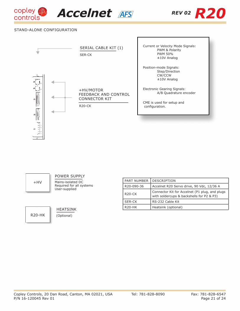
+HV/MOTOR FEEDBACK AND CONTROL CONNECTOR KIT
SER-CK
R20-CK
SERIAL CABLE KIT (1)
POWER SUPPLYMains-isolated DC Required for all systems User-supplied
HEATSINK(Optional)
Current or Velocity Mode Signals: PWM & Polarity PWM 50% ±10V Analog
Position-mode Signals: Step/Direction CW/CCW ±10V Analog
Electronic Gearing Signals: A/B Quadrature encoder
CME is used for setup and configuration.
R20-HK
+HV
STAND-ALONE CONFIGURATION
PART NUMBER DESCRIPTION
R20-090-36 Accelnet R20 Servo drive, 90 Vdc, 12/36 A
R20-CKConnector Kit for Accelnet (P1 plug, and plugs with soldercups & backshells for P2 & P3)
SER-CK RS-232 Cable Kit
R20-HK Heatsink (optional)
REV 02

Accelnet R20AFS
Copley Controls, 20 Dan Road, Canton, MA 02021, USA Tel: 781-828-8090 Fax: 781-828-6547P/N 16-120045 Rev 01 Page 22 of 24
20
30
40
50
60
70
121086420
Continuous Output Current (Adc)
Am
bie
ntT
emp
erat
ure
(˚C
)
Models: R20-055-18, R20-090-09, R20-090-18, R20-090-36HV: 25 Vdc
3
2
1
1 = No heatsink2 = Low profile
heatsink3 = Low profile heatsink
with fan
20
30
40
50
60
70
121086420
Continuous Output Current (Adc)
Am
bie
ntT
emp
erat
ure
(˚C
)
Models: R20-055-18, R20-090-09, R20-090-18, R20-090-36HV: 55 Vdc
3
2
1
1 = No heatsink2 = Low profile
heatsink3 = Low profile heatsink
with fan
The charts below show that maximum ambient temperature vs. continuous output current for the Accelnet R20. The cooling conditions are no heatsink, with heatsink, and heatsink with forced-air from a fan.
MAXIMUM OPERATING TEMPERATURE VS HEATSINK & AIR CIRCULATION
1 = No heatsink 2 = With heatsink 3 = With heatsink + fan
1 = No heatsink 2 = With heatsink 3 = With heatsink + fan
Models: R20-090-09, R20-090-18, R20-090-36 HV: 90 Vdc R20-055-18 HV: 55 Vdc
3
2
1
1 = No heatsink2 = Low profile
heatsink3 = Low profile heatsink
with fan
Am
bien
t Tem
pera
ture
(°C
)
Continuous Output Current (Adc)
Model: R20-090-36 HV: 25 Vdc
Model: R20-090-36 HV: 55 Vdc
Model: R20-090-36 HV: 90 Vdc
REV 02

Accelnet R20AFS
Copley Controls, 20 Dan Road, Canton, MA 02021, USA Tel: 781-828-8090 Fax: 781-828-6547P/N 16-120045 Rev 01 Page 23 of 24
Thermal data for convection-cooling with a heatsink assumes a vertical mounting of the drive on a thermally conducting surface. Heatsink fins run parallel to the long axis of the drive. When fan-cooling is used vertical mounting is not necessary to guarantee thermal performance of the heatsink.
Thermal resistance is a measure of the temperature rise of the drive heatplate due to power dissipation in the drive. It is expressed in units of °C/W where the degrees are the temperature rise above ambient.E.g., an drive dissipating 16 W mounted with no heatsink or fan would see a temperature rise of 46 °C above ambient based on the thermal resistance of 2.9 °C/W. Using the drive maximum heatplate temperature of 70 °C and subtracting 46 °C from that would give 24 °C as the maximum ambient temperature the drive in which the drive could operate before going into thermal shutdown. To operate at higher ambient temperatures a heatsink or forced-air would be required.
END VIEWS VERTICAL MOUNTING
THERMAL RESISTANCEMOUNTING
TOP VIEW VERTICAL MOUNTING
WITH FAN
HEATSINK + FAN °C/W
FORCED-AIR, 300 LFM 0.6
HEATSINK, NO FAN °C/W
CONVECTION 1.7
NO HEATSINK, NO FAN °C/W
CONVECTION 2.9
REV 02

Accelnet R20AFS
Copley Controls, 20 Dan Road, Canton, MA 02021, USA Tel: 781-828-8090 Fax: 781-828-6547P/N 16-120045 Rev 01 Page 24 of 24
MASTER ORDERING GUIDE
Note: Specifications subject to change without notice
Example: Order an R20-090-69 servo drive with associated components: Qty Item Remarks 1 R20-090-36 Accelnet R20 servo drive 1 R20-CK Connector Kit 1 SER-CK Serial Cable Kit
ORDERING EXAMPLE
Contact factory for RS-422 option
PART NUMBER DESCRIPTION
R20-090-36 Accelnet R20 Servo drive, 90 Vdc, 12/36 A
ACCESSORIES
16-0120045 Document Revision HistoryRevision Date Remarks
00 Aug 22, 2018 Initial released version
01 Sep 22, 2020 Added p. 15 showing Biss-C feedback, -S option dropped, feature is now standard, REV 02 replaces REV 01, all models except R20-090-36 are removed. add UR logo
QTY REF DESCRIPTION PART NUMBER
Connector Kit R20-CK
1 J1 Connector, 6 Terminal, 5.08 mm Amphenol: ELFP06210
1J3
26 Pin Connector, High Density, D-Sub, Solder Cup Norcomp: 180-026-103L001
1 26 Pin Connector Backshell Norcomp: 979-015-020R121
1J2
15 Pin Connector, High Density, D-Sub, Solder Cup Norcomp: 180-015-103L001
1 15 Pin Connector Backshell Norcomp: 979-009-020R121
CANopen Network Kit R20-NK
1
J4-J5
Adapter Assy, DB9 Female to RJ45 Jack (R20-CV)
1 CANopen Network Cable, 10 ft. (R20-NC-10)
1 CANopen Network Terminator (R20-NT)
R20-NC-10
J4-J5
CANopen Network Cable, 10 ft
R20-NC-01 CANopen network cable, 1 ft
R20-NT CANopen Network Terminator Lcom: SP15731-OD1
SER-CK J6 Serial Cable Kit
R20-CV J4-J5 Adapter Assy, DB9 Female to RJ45 Jack
Heatsink Kit R20-HK
1
N/A
Heatsink, Low Profile
1 Heatsink Thermal Material
4 Heatsink Hardware
REV 02