accelerator possibilities for enhanced time resolved
TRANSCRIPT
Pioneering Science andTechnology
Office of Science U.S. Department
of EnergyM. Borland, 1/26/05Accelerator Possibilities for Enhanced TimeResolved
Imaging at APS
Michael BorlandOperations Analysis Group
APS Operations DivisionJanuary 26, 2005
A U.S. Department of EnergyOffice of Science LaboratoryOperated by The University of ChicagoOffice of Science
U.S. Department of Energy
Accelerator Possibilities for Enhanced Time
Resolved Imaging at APS

Pioneering Science andTechnology
Office of Science U.S. Department
of EnergyM. Borland, 1/26/05Accelerator Possibilities for Enhanced TimeResolved
Imaging at APS
● Background
– AP101: A review of relevant accelerator physics● Review of types of improvements
– What's the limitation now
– What might be done about it
– Benefits, costs, and tradeoffs
– Activities and plans● Summary
Outline
Pioneering Science andTechnology
Office of Science U.S. Department
of EnergyM. Borland, 1/26/05Accelerator Possibilities for Enhanced TimeResolved
Imaging at APS
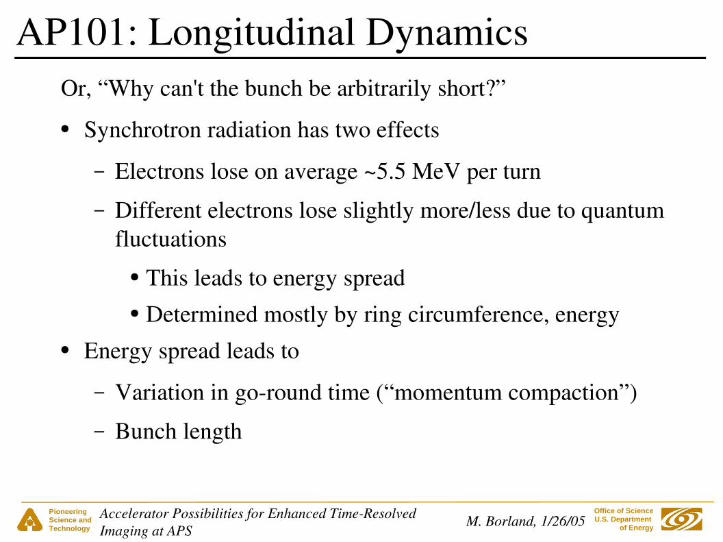
Or, “Why can't the bunch be arbitrarily short?”
● Synchrotron radiation has two effects
– Electrons lose on average ~5.5 MeV per turn
– Different electrons lose slightly more/less due to quantum fluctuations
● This leads to energy spread● Determined mostly by ring circumference, energy
● Energy spread leads to
– Variation in goround time (“momentum compaction”)
– Bunch length
AP101: Longitudinal Dynamics

Pioneering Science andTechnology
Office of Science U.S. Department
of EnergyM. Borland, 1/26/05Accelerator Possibilities for Enhanced TimeResolved
Imaging at APS
5.5 MeV
time
voltage
AP101: Longitudinal Dynamics
● Highpower rf systems restore beam energy
● Provide focusing force that prevents bunch length from growing indefinitely
● Minimum possible bunch length is set by
– Rf slope
– Momentum compaction
– Energy spread
Pioneering Science andTechnology
Office of Science U.S. Department
of EnergyM. Borland, 1/26/05Accelerator Possibilities for Enhanced TimeResolved
Imaging at APS
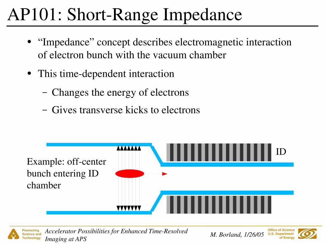
● “Impedance” concept describes electromagnetic interaction of electron bunch with the vacuum chamber
● This timedependent interaction
– Changes the energy of electrons
– Gives transverse kicks to electrons
AP101: ShortRange Impedance
Example: offcenterbunch entering ID chamber
ID

Pioneering Science andTechnology
Office of Science U.S. Department
of EnergyM. Borland, 1/26/05Accelerator Possibilities for Enhanced TimeResolved
Imaging at APS
AP101: ShortRange Impedance
Fields are reflectedfrom the transitionand act back on bunch
Tail of bunch is deflected andloses energy
● In APS, this generally results in
– Bunch lengthening, then
– Transverse instability, then
– Energy spread growth● We'll look at possible remedies later
Pioneering Science andTechnology
Office of Science U.S. Department
of EnergyM. Borland, 1/26/05Accelerator Possibilities for Enhanced TimeResolved
Imaging at APS
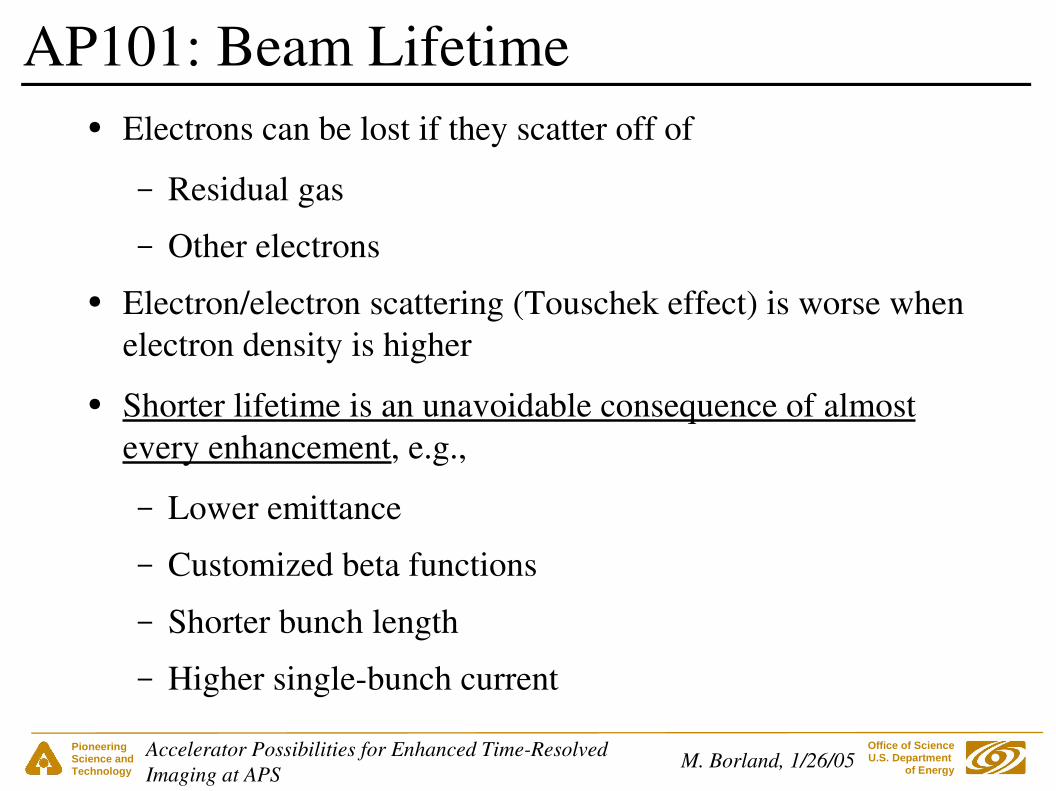
● Electrons can be lost if they scatter off of
– Residual gas
– Other electrons● Electron/electron scattering (Touschek effect) is worse when
electron density is higher
● Shorter lifetime is an unavoidable consequence of almost every enhancement, e.g.,
– Lower emittance
– Customized beta functions
– Shorter bunch length
– Higher singlebunch current
AP101: Beam Lifetime

Pioneering Science andTechnology
Office of Science U.S. Department
of EnergyM. Borland, 1/26/05Accelerator Possibilities for Enhanced TimeResolved
Imaging at APS
● Use a higheremittance lattice– Reverting to 8 nm would raise 7 hr lifetime to 20 hr1
– Not a popular option● Increase the vertical emittance
– Not quite as unpopular– Limited benefit before it hurts injection efficiency
● Could use pulsed skew quads to solve this● Add harmonic rf system to increase the bunch length2
– Quite expensive (~8M$)
– Needs half a straight section
– Few Users want longer bunches
AP101: Remedies for Lifetime Decrease
1L. Emery2M. Borland, OAGTN2005003Cost guess from data by G. Pile et al.
Pioneering Science andTechnology
Office of Science U.S. Department
of EnergyM. Borland, 1/26/05Accelerator Possibilities for Enhanced TimeResolved
Imaging at APS
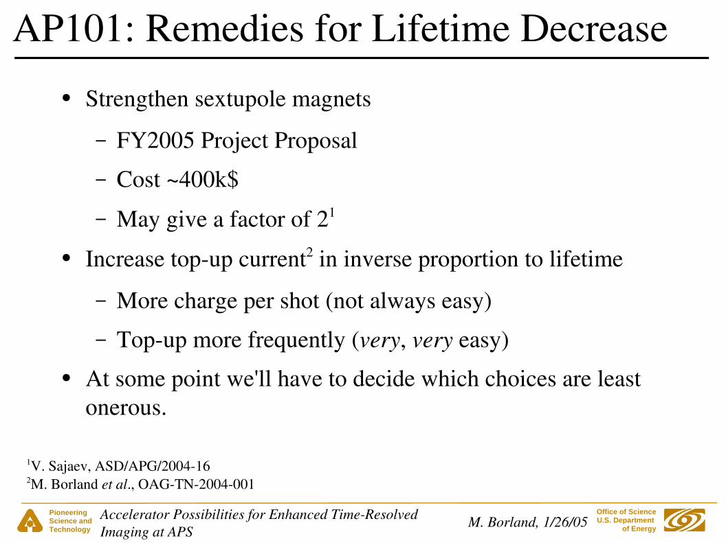
AP101: Remedies for Lifetime Decrease
1V. Sajaev, ASD/APG/2004162M. Borland et al., OAGTN2004001
● Strengthen sextupole magnets
– FY2005 Project Proposal
– Cost ~400k$
– May give a factor of 21
● Increase topup current2 in inverse proportion to lifetime
– More charge per shot (not always easy)
– Topup more frequently (very, very easy)● At some point we'll have to decide which choices are least
onerous.

Pioneering Science andTechnology
Office of Science U.S. Department
of EnergyM. Borland, 1/26/05Accelerator Possibilities for Enhanced TimeResolved
Imaging at APS
Bunch Lengths for Different APS Fill Patterns
25 psSinglet: 50 ps
Septuplet: 32 ps40 ps
Bunch length (rms)
324-singletsHybrid: 1+8*724-singlets
T1 (5 µs range)
24-singlets
T1 (5 µs range)
1+8*7
T1 (5 µs range)
324-singlets
Courtesy of A. Lumpkin and B. Yang
Data from Sector 35 DualSweep Streak Camera
T2
(1
ns r
ange
)
T2
(1
ns r
ange
)
T2
(1
ns r
ange
)
Pioneering Science andTechnology
Office of Science U.S. Department
of EnergyM. Borland, 1/26/05Accelerator Possibilities for Enhanced TimeResolved
Imaging at APS
1. Improved bunch purity
2. Higher singlebunch current
3. Shorter equilibrium bunch
4. Transient concepts
5. Zholents' transverse rf chirp concept
Possible Improvements for TimeResolved Imaging

Pioneering Science andTechnology
Office of Science U.S. Department
of EnergyM. Borland, 1/26/05Accelerator Possibilities for Enhanced TimeResolved
Imaging at APS
● APS accumulator ring (PAR) creates single bunches for the storage ring
● Performance as good as 106 seen, but sometimes can't maintain better than 103
● A prototype PAR bunch cleaning system+ used at end of last run and maintained 106*
● FY2005 Project Proposal to build permanent system with target of better than 106
● Also revisiting bunch cleaning in storage ring itself
1: Bunch Purity
*A. Lumpkin+CY Yao et al., OAGTN2004051

Pioneering Science andTechnology
Office of Science U.S. Department
of EnergyM. Borland, 1/26/05Accelerator Possibilities for Enhanced TimeResolved
Imaging at APS
● Presently limited to 8~10 mA in a single bunch
● Raising limit would permit
– More intense bunch for hybrid mode.
– Fewbunch modes (e.g., 100mA in 6 bunches).
– More current in 24 bunch mode (e.g., 200mA in 24)1
● Limit imposed by singlebunch transverse instability
2: Single Bunch Current Limit
● Related to characteristics of ID chambers
– Small gap
– Transition geometry
– Material conductivity
1J.M. Gibson

Pioneering Science andTechnology
Office of Science U.S. Department
of EnergyM. Borland, 1/26/05Accelerator Possibilities for Enhanced TimeResolved
Imaging at APS
● Modify the ID chambers
– Redesign transition or silvercoat chambers themselves● Not clear which will help most and by how much● Extensive simulation studies and more experiments
needed– Increase chamber apertures
● Reduced scan range● ID redesigns might be needed● Benefits also uncertain at this point
2: Possibilities for Raising the Limit
Pioneering Science andTechnology
Office of Science U.S. Department
of EnergyM. Borland, 1/26/05Accelerator Possibilities for Enhanced TimeResolved
Imaging at APS
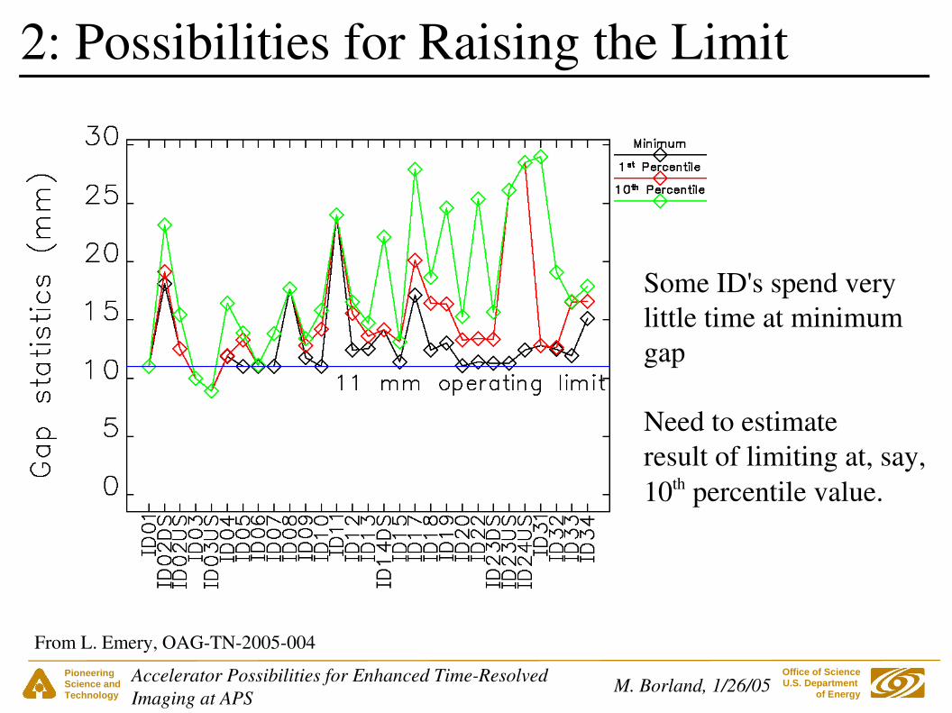
2: Possibilities for Raising the Limit
Some ID's spend verylittle time at minimumgap
Need to estimateresult of limiting at, say,10th percentile value.
From L. Emery, OAGTN2005004
Pioneering Science andTechnology
Office of Science U.S. Department
of EnergyM. Borland, 1/26/05Accelerator Possibilities for Enhanced TimeResolved
Imaging at APS
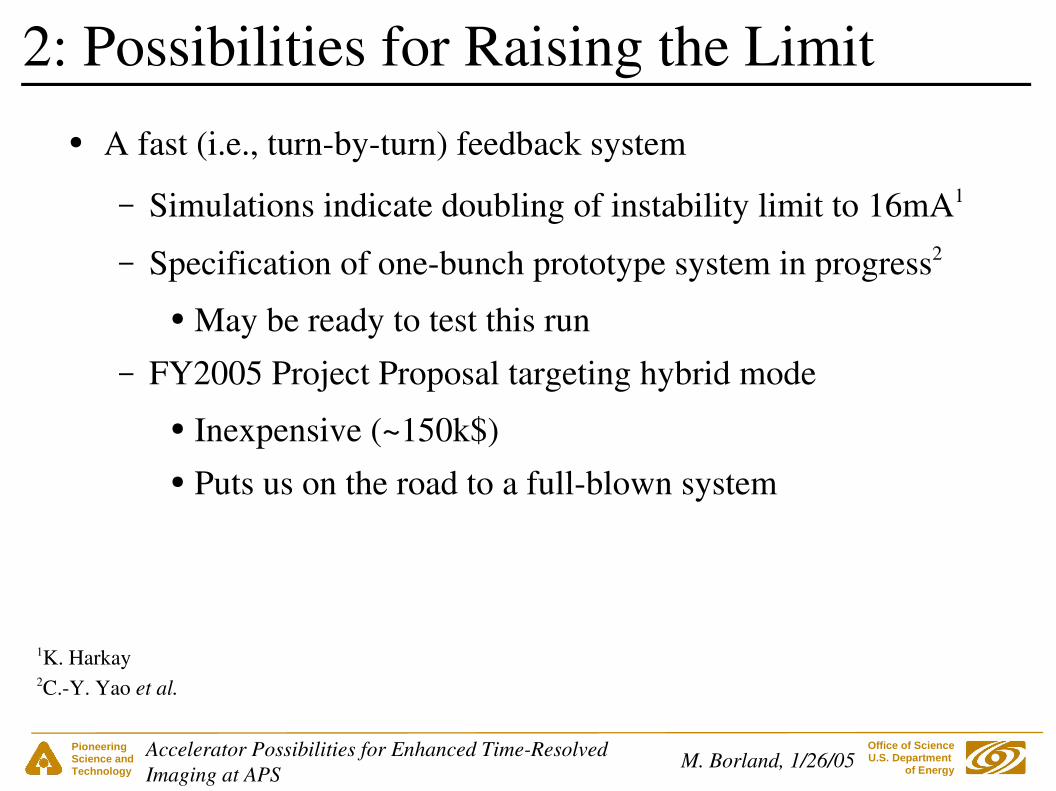
● A fast (i.e., turnbyturn) feedback system
– Simulations indicate doubling of instability limit to 16mA1
– Specification of onebunch prototype system in progress2
● May be ready to test this run– FY2005 Project Proposal targeting hybrid mode
● Inexpensive (~150k$)● Puts us on the road to a fullblown system
2: Possibilities for Raising the Limit
1K. Harkay2C.Y. Yao et al.
Pioneering Science andTechnology
Office of Science U.S. Department
of EnergyM. Borland, 1/26/05Accelerator Possibilities for Enhanced TimeResolved
Imaging at APS
● Stronger sextupoles
– Used to increase chromaticity and stabilize beam
– Used to improve energy aperture and hence lifetime
– Would let us go to higher single bunch current with good lifetime
– FY2005 project proposal (~400k$) for stronger sextupoles
2: Possibilities for Raising the Limit

Pioneering Science andTechnology
Office of Science U.S. Department
of EnergyM. Borland, 1/26/05Accelerator Possibilities for Enhanced TimeResolved
Imaging at APS
● These two projects can be used separately or together
– Use feedback to stablize the beam to ~2x current
– Use stronger sextupoles to get the lifetime back● What might be seen if this works out?
2: Possibilities for Raising the Limit
Pioneering Science andTechnology
Office of Science U.S. Department
of EnergyM. Borland, 1/26/05Accelerator Possibilities for Enhanced TimeResolved
Imaging at APS
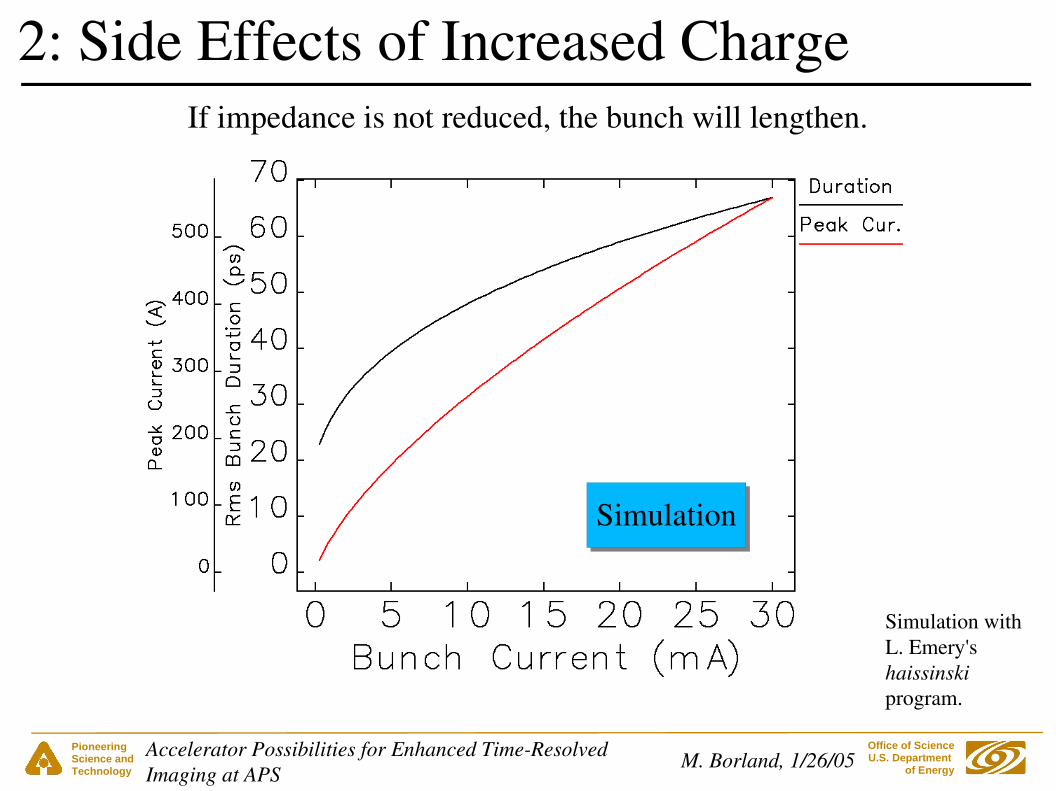
2: Side Effects of Increased Charge
Simulation
If impedance is not reduced, the bunch will lengthen.
Simulation withL. Emery'shaissinskiprogram.

Pioneering Science andTechnology
Office of Science U.S. Department
of EnergyM. Borland, 1/26/05Accelerator Possibilities for Enhanced TimeResolved
Imaging at APS
2: Side Effects of Increased Charge
Y.C. Chae et al., PAC 2001
Energy spread will increase, increasing the effective emittance.
Estimate 0.125% for 30mA, giving 10% increase in effective emittance
Pioneering Science andTechnology
Office of Science U.S. Department
of EnergyM. Borland, 1/26/05Accelerator Possibilities for Enhanced TimeResolved
Imaging at APS
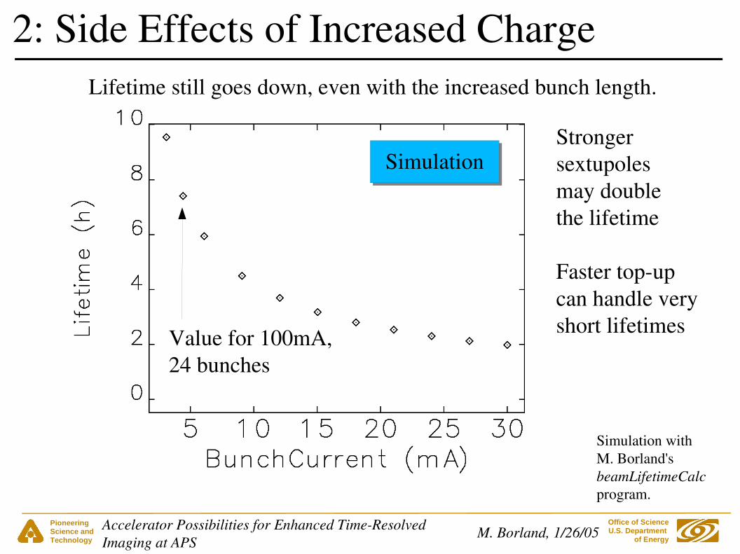
2: Side Effects of Increased Charge Lifetime still goes down, even with the increased bunch length.
Value for 100mA, 24 bunches
Strongersextupolesmay doublethe lifetime
Faster topupcan handle veryshort lifetimes
Simulation
Simulation withM. Borland'sbeamLifetimeCalcprogram.
Pioneering Science andTechnology
Office of Science U.S. Department
of EnergyM. Borland, 1/26/05Accelerator Possibilities for Enhanced TimeResolved
Imaging at APS
● As just seen, bunch naturally gets longer as singlebunch current increases
● By itself, a longer bunch is beneficial
– Increases lifetime (or limits decrease)
– Delays onset of instabilities
● If we have other ways to manage those issues, what could we do?
3: Limitations on Decreasing Bunch Length

Pioneering Science andTechnology
Office of Science U.S. Department
of EnergyM. Borland, 1/26/05Accelerator Possibilities for Enhanced TimeResolved
Imaging at APS
1. Reduce the longitudinal machine impedance
● Modify ID chambers
– Better transitions and/or conductivity
– Larger gaps where possible● Will also increase single bunch limit
● Again, extensive simulation required
● Best possible result is uninspiring:
– 20 ps rms (present zerocurrent bunch length)
3: Possibilities for Decreasing Bunch Length
Pioneering Science andTechnology
Office of Science U.S. Department
of EnergyM. Borland, 1/26/05Accelerator Possibilities for Enhanced TimeResolved
Imaging at APS
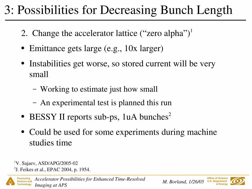
2. Change the accelerator lattice (“zero alpha”)1
● Emittance gets large (e.g., 10x larger)
● Instabilities get worse, so stored current will be very small
– Working to estimate just how small
– An experimental test is planned this run
● BESSY II reports subps, 1uA bunches2
● Could be used for some experiments during machine studies time
3: Possibilities for Decreasing Bunch Length
1V. Sajaev, ASD/APG/2005022J. Feikes et al., EPAC 2004, p. 1954.

Pioneering Science andTechnology
Office of Science U.S. Department
of EnergyM. Borland, 1/26/05Accelerator Possibilities for Enhanced TimeResolved
Imaging at APS
3. Add a higherharmonic rf system
● Increases restoring force that opposes bunch lengthening
● 50% decrease requires a ~12M$ superconducting rf system
● Probably requires at least a full straight section
● Extensive study needed to look at instability issues
3: Possibilities for Decreasing Bunch Length
M. Borland, OAGTN2005003Cost guess from data by G. Pile et al.

Pioneering Science andTechnology
Office of Science U.S. Department
of EnergyM. Borland, 1/26/05Accelerator Possibilities for Enhanced TimeResolved
Imaging at APS
● Decreasing the equilibrium bunch length is difficult
– New ID chambers: expensive, can't go below 20 ps rms
– Harmonic rf system: expensive even for 50% decrease
– Zero alpha lattice: cheap, but current likely very low
● Nonequilibrium manipulations may work...
3: Possibilities for Decreasing Bunch Length

Pioneering Science andTechnology
Office of Science U.S. Department
of EnergyM. Borland, 1/26/05Accelerator Possibilities for Enhanced TimeResolved
Imaging at APS
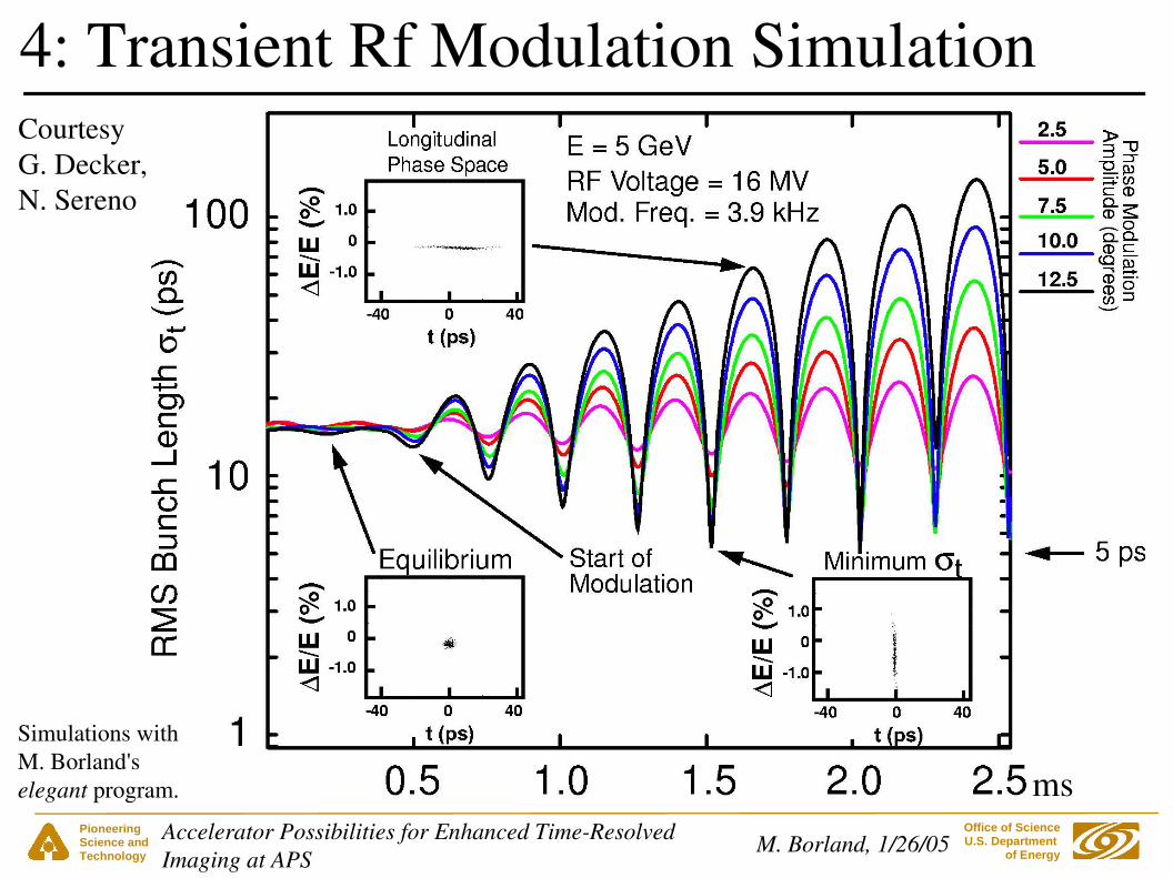
● Involves phase modulation of storage ring rf systems
● ~8 ps rms bunch length might be possible, however
– Assumes 6 GeV operation
– Blow up in energy spread and effective emittance
– Duty factor limited to ~100 Hz by damping time● Further tricks might fix these, however
– ~5 ps rms possible at 5 GeV
● Requires little or no new accelerator hardware
● Would affect all bunches
4: Transient Rf Modulation1
1G. Decker
Pioneering Science andTechnology
Office of Science U.S. Department
of EnergyM. Borland, 1/26/05Accelerator Possibilities for Enhanced TimeResolved
Imaging at APS
4: Transient Rf Modulation Simulation
ms
CourtesyG. Decker,N. Sereno
Simulations withM. Borland'selegant program.

Pioneering Science andTechnology
Office of Science U.S. Department
of EnergyM. Borland, 1/26/05Accelerator Possibilities for Enhanced TimeResolved
Imaging at APS
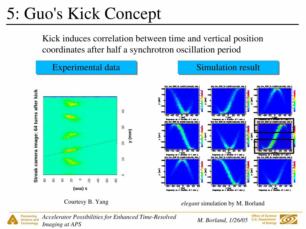
● In this proposal, the bunch is kicked vertically and allowed to oscillate
● A correlation between time and vertical coordinates develops due to
– Variation of oscillation frequency with energy offset (“chromaticity”)
– Time/energy oscillations due to rf system
● Correlation allows compression or spatial filtering to produce a shorter pulse
● Requires no new accelerator hardware
● Verified by simulation and experiment
5: Guo's Kick Concept
Pioneering Science andTechnology
Office of Science U.S. Department
of EnergyM. Borland, 1/26/05Accelerator Possibilities for Enhanced TimeResolved
Imaging at APS
5: Guo's Kick ConceptS
trea
k ca
mer
a im
age:
64
turn
s af
ter
kick
y (m
m)
010
2030
40
s (mm)
-80
-60
-40
-20020406080
Courtesy B. Yang
Experimental data
elegant simulation by M. Borland
Simulation result
Kick induces correlation between time and vertical positioncoordinates after half a synchrotron oscillation period
Pioneering Science andTechnology
Office of Science U.S. Department
of EnergyM. Borland, 1/26/05Accelerator Possibilities for Enhanced TimeResolved
Imaging at APS
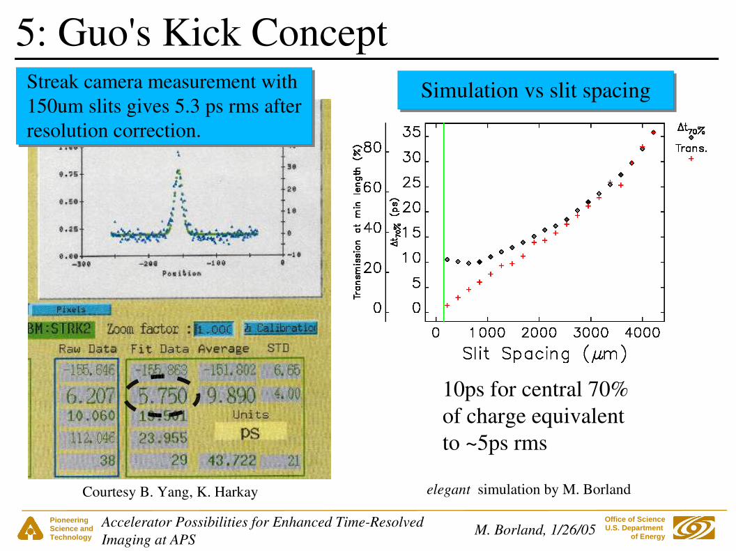
5: Guo's Kick Concept
Courtesy B. Yang, K. Harkay
Streak camera measurement with150um slits gives 5.3 ps rms afterresolution correction.
Simulation vs slit spacing
elegant simulation by M. Borland
10ps for central 70%of charge equivalentto ~5ps rms

Pioneering Science andTechnology
Office of Science U.S. Department
of EnergyM. Borland, 1/26/05Accelerator Possibilities for Enhanced TimeResolved
Imaging at APS
● Repetition rate limited to 40 Hz● Works only for low intensity (~0.2 mA/bunch)
5: Limitations and Problems
elegantsimulation byM. Borland
Kick this bunch only
● Consider special fill with one isolated bunch and faster kicker
● Vertical emittance is blown up for ~30ms

Pioneering Science andTechnology
Office of Science U.S. Department
of EnergyM. Borland, 1/26/05Accelerator Possibilities for Enhanced TimeResolved
Imaging at APS
6: Zholents' Transverse Rf Chirp Concept
Radiation fromhead electrons
Radiation fromtail electrons
Cavity frequencyis harmonic h ofring rf frequency
RF deflecting cavity RF deflecting cavity
(Adapted from A. Zholents' August 30, 2004 presentation at APS Strategic Planning Meeting.)
t
y
Ideally, second cavityexactly cancels effectof first
Undulator
Pulse can be slicedor compressed withasymmetric cutcrystal

Pioneering Science andTechnology
Office of Science U.S. Department
of EnergyM. Borland, 1/26/05Accelerator Possibilities for Enhanced TimeResolved
Imaging at APS
● We've made significant progress on a feasibility study, covering
– Lattice options– Beam dynamics and tolerances– Instabilities– Lifetime limits– Compression and optimization– Undulator properties and compression– Xray optics– Rf system
6: APS Feasibility Study
Participants include: M. Borland, YC Chae, R. Dejus, L. Emery, K. Harkay, D. Horan,R. Kustom, D. Mills, S. Milton, G. Pile, V. Sajaev, S. Shastri, G. Waldschmidt, M. White

Pioneering Science andTechnology
Office of Science U.S. Department
of EnergyM. Borland, 1/26/05Accelerator Possibilities for Enhanced TimeResolved
Imaging at APS
Slits and verticalfocusing mirror
6: APS Optics Concept for 10 kV
After S. Shastri, APS
focus 45mdownstream
N.B.: Sketch not to scale.Angles are exaggerated.
30m
Undulator Tailradiation
Headradiation
About 30% of photons that getthrough slits get through the compression optics.
Asymmetriccut Si(400)crystal
Symmetriccut Si(400)crystal
Pioneering Science andTechnology
Office of Science U.S. Department
of EnergyM. Borland, 1/26/05Accelerator Possibilities for Enhanced TimeResolved
Imaging at APS
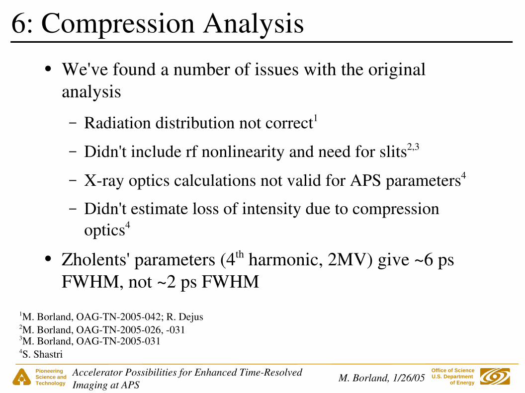
● We've found a number of issues with the original analysis
– Radiation distribution not correct1
– Didn't include rf nonlinearity and need for slits2,3
– Xray optics calculations not valid for APS parameters4
– Didn't estimate loss of intensity due to compression optics4
● Zholents' parameters (4th harmonic, 2MV) give ~6 ps FWHM, not ~2 ps FWHM
6: Compression Analysis
1M. Borland, OAGTN2005042; R. Dejus2M. Borland, OAGTN2005026, 031
4S. Shastri
3M. Borland, OAGTN2005031
Pioneering Science andTechnology
Office of Science U.S. Department
of EnergyM. Borland, 1/26/05Accelerator Possibilities for Enhanced TimeResolved
Imaging at APS
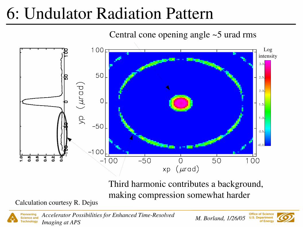
6: Undulator Radiation Pattern
Calculation courtesy R. Dejus
Central cone opening angle ~5 urad rmsLog
intensity
Third harmonic contributes a background,making compression somewhat harder

Pioneering Science andTechnology
Office of Science U.S. Department
of EnergyM. Borland, 1/26/05Accelerator Possibilities for Enhanced TimeResolved
Imaging at APS
● Reduce radiation opening angle– Use a longer ID– Use a shorter xray wavelength if possible
● Increase the chirp– Increase voltage
● Lifetime limits us to ~7MV– Increase harmonic number
● Power source availability up to h=8 (2.8 GHz)1
– Makes emittance increase worse
6: Achieving More Compression
M. Borland, OAGTN2004031, 035, 0421D. Horan
Pioneering Science andTechnology
Office of Science U.S. Department
of EnergyM. Borland, 1/26/05Accelerator Possibilities for Enhanced TimeResolved
Imaging at APS
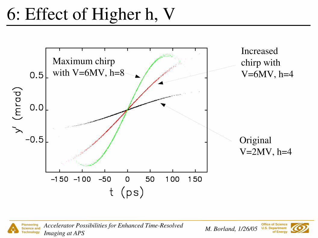
6: Effect of Higher h, V
Original V=2MV, h=4
Increased chirp withV=6MV, h=4
Maximum chirpwith V=6MV, h=8
Pioneering Science andTechnology
Office of Science U.S. Department
of EnergyM. Borland, 1/26/05Accelerator Possibilities for Enhanced TimeResolved
Imaging at APS
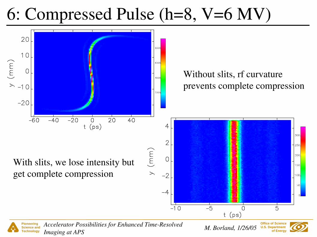
6: Compressed Pulse (h=8, V=6 MV)
Without slits, rf curvatureprevents complete compression
With slits, we lose intensity butget complete compression
Pioneering Science andTechnology
Office of Science U.S. Department
of EnergyM. Borland, 1/26/05Accelerator Possibilities for Enhanced TimeResolved
Imaging at APS
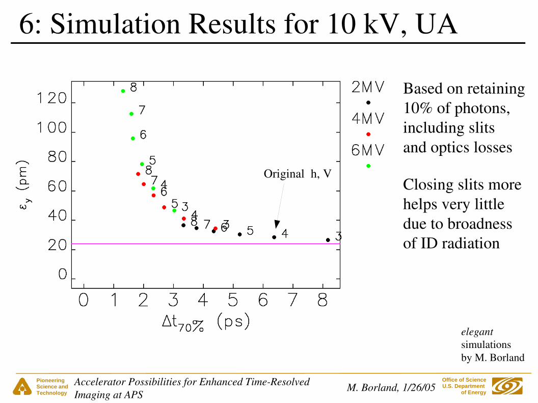
6: Simulation Results for 10 kV, UA
Based on retaining10% of photons,including slitsand optics losses
Original h, V
elegantsimulationsby M. Borland
Closing slits morehelps very littledue to broadnessof ID radiation
Pioneering Science andTechnology
Office of Science U.S. Department
of EnergyM. Borland, 1/26/05Accelerator Possibilities for Enhanced TimeResolved
Imaging at APS
● If kick cancellation is not exact, vertical emittance will increase
● Many possible causes of imperfect cancellation
– Lattice coupling between cavities– Roll of cavities about beam axis– Lattice errors– Rf phasing and voltage errors– Sextupole nonlinearity– Chromaticity and beam energy spread– Momentum compaction and beam energy spread
6: Causes of Increased Emittance
See M. Borland, OAGTN2004026, OAGTN2004027, OAGTN2004054
Pioneering Science andTechnology
Office of Science U.S. Department
of EnergyM. Borland, 1/26/05Accelerator Possibilities for Enhanced TimeResolved
Imaging at APS
● Turn off interior sextupoles
– Hurts lifetime, but necessary for V>2 MV
– Included in the simulations already
● Can offset ~20 pm of increase by lowering the emittance ratio ahead of time1
● Use to improve injection efficiency and control lifetime:
– Tune APS for lowest vertical coupling● Gives best injection efficiency● Cavities raise vertical emittance and hence lifetime
6: Managing Vertical Emittance Effects
1V. Sajaev

Pioneering Science andTechnology
Office of Science U.S. Department
of EnergyM. Borland, 1/26/05Accelerator Possibilities for Enhanced TimeResolved
Imaging at APS
● Improved bunch purity– FY2005 project proposal for PAR bunch cleaner
– Anticipate improvement in near future● Virtual guarantee of high purity● Anticipate better than 106
● More single bunch current
– Two FY2005 project proposals address this
– Prediction of 16 mA in hybrid mode with good lifetime
Summary
Pioneering Science andTechnology
Office of Science U.S. Department
of EnergyM. Borland, 1/26/05Accelerator Possibilities for Enhanced TimeResolved
Imaging at APS
● Shorter equilibrium bunches– Difficult and expensive to make improvements
– ~2fold reduction in bunch length probably doesn't justify expense
– Zeroalpha lattice may be interesting to some, but current is low
● Transient schemes
– Two concepts under exploration
– These require little new hardware
– Guo's concept has already shown results
– Repetition rate, beam disruption, intensity are issues
Summary

Pioneering Science andTechnology
Office of Science U.S. Department
of EnergyM. Borland, 1/26/05Accelerator Possibilities for Enhanced TimeResolved
Imaging at APS
● Rf chirping
– Extensive investigation performed, ongoing
– No show stoppers seen, but harder than expected● 1~2 ps FWHM● 10% intensity● ~100 pm vertical emittance (4 times present)● Short lifetime (~3 hours?)
– Very expensive (~10M$1)
Summary
1G. Pile, et al.

Pioneering Science andTechnology
Office of Science U.S. Department
of EnergyM. Borland, 1/26/05Accelerator Possibilities for Enhanced TimeResolved
Imaging at APS
● Many possibilities for enhanced timeresolved imaging● Some have significant cost and downsides that must be
weighed against the benefits● Much ongoing activity on this subject
● Good reason to think we can significantly enhance the APS for timeresolved applications
Conclusion