accelerator and interaction region
DESCRIPTION
Accelerator and Interaction Region. Alex Bogacz Center for Advanced Studies of Accelerators. EIC Detector Workshop at Jefferson Lab June 4-5, 2010. EIC Efforts at JLab. For over a year… - PowerPoint PPT PresentationTRANSCRIPT
Accelerator and Interaction Region
Alex Bogacz
Center for Advanced Studies of Accelerators
EIC Detector Workshop at Jefferson LabJune 4-5, 2010
EIC Efforts at JLab
For over a year…
We have explored a staged approach to EIC, focusing on science cases and accelerator designs for a low-to-medium energy EIC with similar design features (high luminosity (>1034), polarization (>80%), multiple detectors)
We have developed a conceptual design of a low-to-medium energy EIC based on CEBAF, and have therefore reduced the detector and accelerator technology R&D significantly, yielding a large cost saving compared to the full energy collider.
We are now engaged in accelerator design, optimizations and staged R&D for enabling technologies.
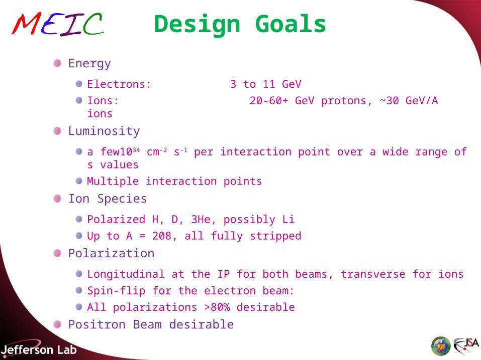
Design Goals
Energy
Electrons: 3 to 11 GeV
Ions: 20-60+ GeV protons, ~30 GeV/A ions
Luminosity
a few1034 cm-2 s-1 per interaction point over a wide range of s values
Multiple interaction points
Ion Species
Polarized H, D, 3He, possibly Li
Up to A = 208, all fully stripped
Polarization
Longitudinal at the IP for both beams, transverse for ions
Spin-flip for the electron beam:
All polarizations >80% desirable
Positron Beam desirable
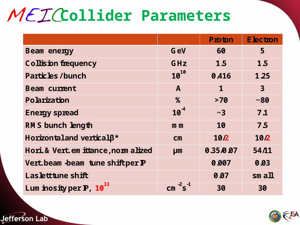
Collider Parameters
Proton Electron
Beam energy GeV 60 5
Collision frequency GHz 1.5 1.5
Particles / bunch 1010
0.416 1.25
Beam current A 1 3
Polarization % >70 ~80
Energy spread 10-4
~3 7.1
RMS bunch length mm 10 7.5
Horizontal and vertical β* cm 10/2 10/2
Hori. & Vert. emittance, normalized μm 0.35/0.07 54/11
Vert. beam-beam tune shift per IP 0.007 0.03
Laslett tune shift 0.07 small
Luminosity per IP, 1033
cm-2
s-1
30 30
Design Features
High luminosity at medium energy range
Enabled by short ion bunches, low β*, high rep. rate
Require crab crossing colliding beams
Electron cooling is an essential part of MEIC
Multiple IPs (detectors)
“Figure-8” electron and ion collider rings
Ensure spin preservation & ease spin manipulations
No spin sensitivity to energy for all species.
12 GeV CEBAF injector meets storage-ring polarized beam
requirements, can serve as a full energy injector
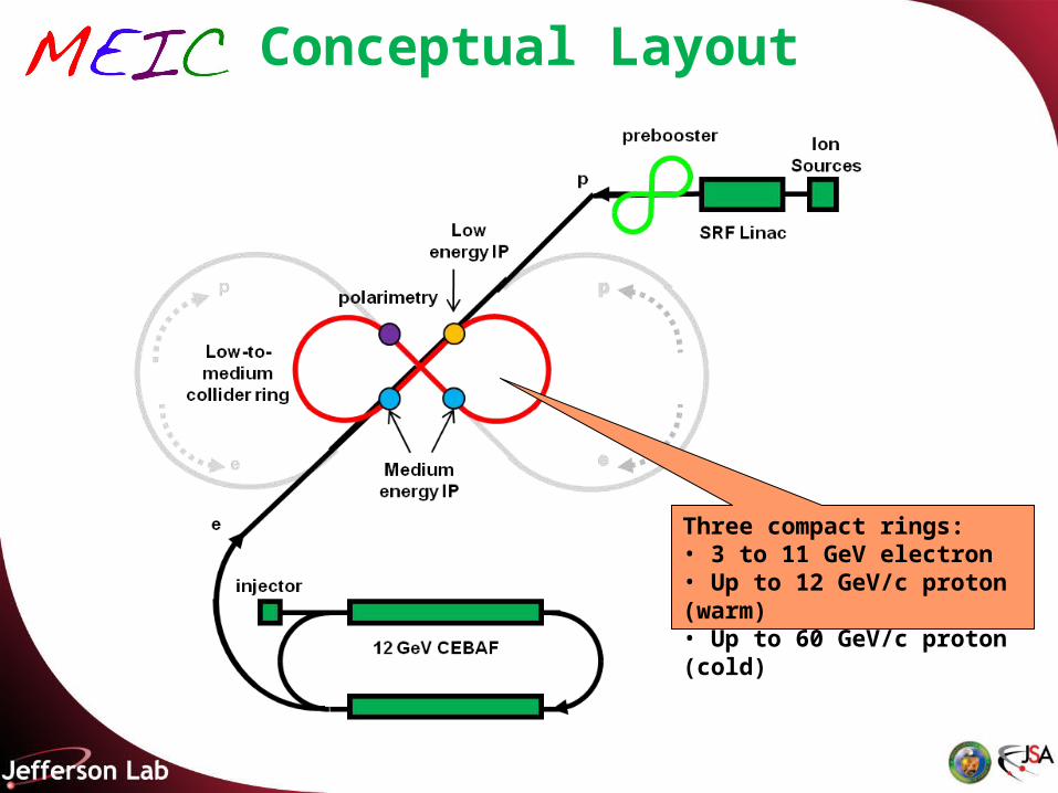
Conceptual Layout
Three compact rings:• 3 to 11 GeV electron• Up to 12 GeV/c proton (warm)• Up to 60 GeV/c proton (cold)
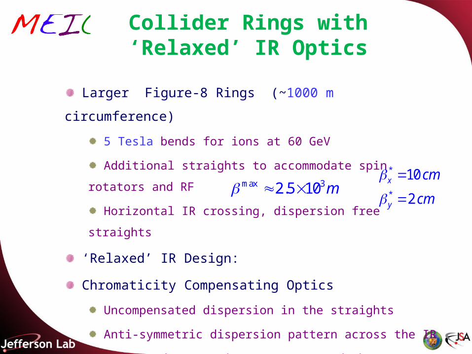
Collider Rings with ‘Relaxed’ IR Optics
Larger Figure-8 Rings (~1000 m circumference)
5 Tesla bends for ions at 60 GeV
Additional straights to accommodate spin rotators and RF
Horizontal IR crossing, dispersion free straights
‘Relaxed’ IR Design:
Chromaticity Compensating Optics
Uncompensated dispersion in the straights
Anti-symmetric dispersion pattern across the IR
Dedicated Symmetric Inserts around the IR
Electron Collider Ring based on emittance preserving Optics
max 32.5 10 m *
*
10
2
x
y
cm
cm
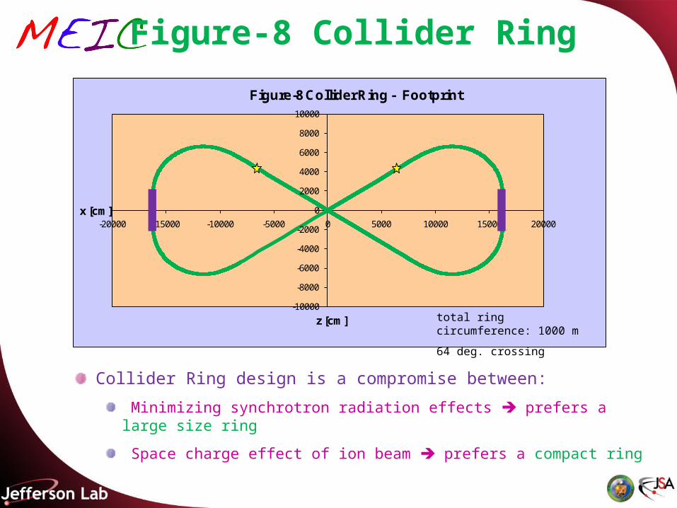
Figure-8 Collider Ring
Collider Ring design is a compromise between:
Minimizing synchrotron radiation effects prefers a large size ring
Space charge effect of ion beam prefers a compact ring
-10000
-8000
-6000
-4000
-2000
0
2000
4000
6000
8000
10000
-20000 -15000 -10000 -5000 0 5000 10000 15000 20000x [cm]
z [cm]
Figure-8 Collider Ring - Footprint
total ring circumference: 1000 m
64 deg. crossing
Arc quadrupoles:
$Lb=40 cm
$G= 14.4 kGauss/cm
100
Tue Mar 30 14:00:41 2010 OptiM - MAIN: - N:\bogacz\ELIC\MEIC\Optics\Ion Ring\cell_90_in.opt
0.2
50
PH
AS
E_
X&
Y
Q_X Q_Y
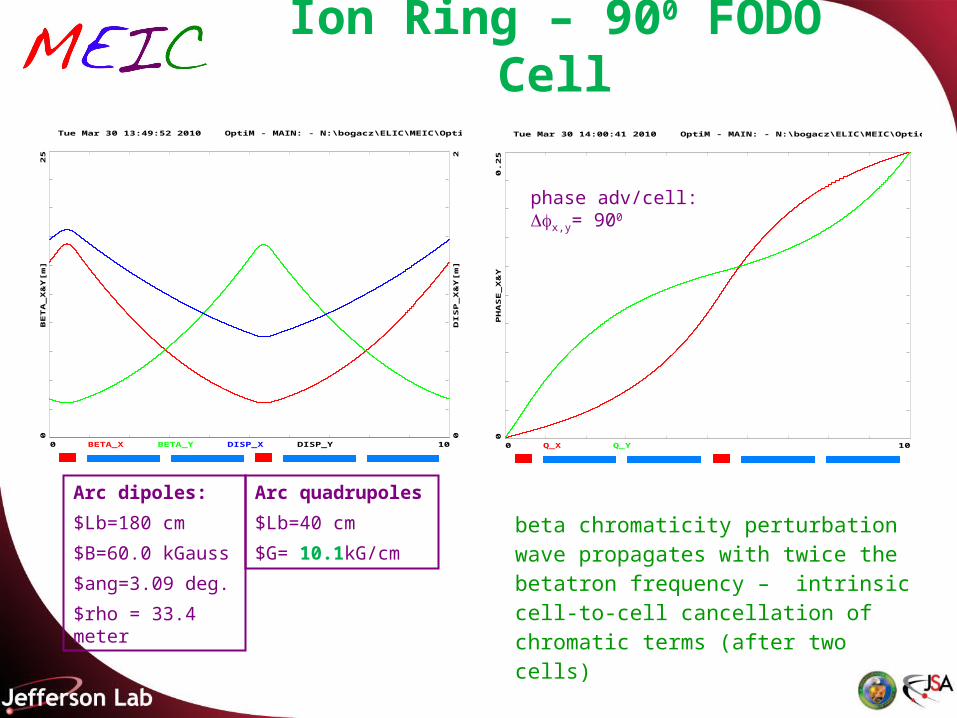
Ion Ring – 900 FODO Cell
100
Tue Mar 30 13:49:52 2010 OptiM - MAIN: - N:\bogacz\ELIC\MEIC\Optics\Ion Ring\cell_90_in.opt
25
0
20
BE
TA
_X
&Y
[m]
DIS
P_
X&
Y[m
]BETA_X BETA_Y DISP_X DISP_Y
phase adv/cell: x,y= 900
Arc dipoles:
$Lb=180 cm
$B=60.0 kGauss
$ang=3.09 deg.
$rho = 33.4 meter
beta chromaticity perturbation wave propagates with twice the betatron frequency – intrinsic cell-to-cell cancellation of chromatic terms (after two cells)
Arc quadrupoles
$Lb=40 cm
$G= 10.1kG/cm
2600
Tue Mar 30 14:23:52 2010 OptiM - MAIN: - N:\bogacz\ELIC\MEIC\Optics\Ion Ring\Arc_full_90_in.opt
25
0
2-2
BE
TA
_X
&Y
[m]
DIS
P_
X&
Y[m
]
BETA_X BETA_Y DISP_X DISP_Y
Ion Ring - Arc Optics
Straight – 20 meter Arc – 120 meter
248 deg. Arc
Arc – 120 meter
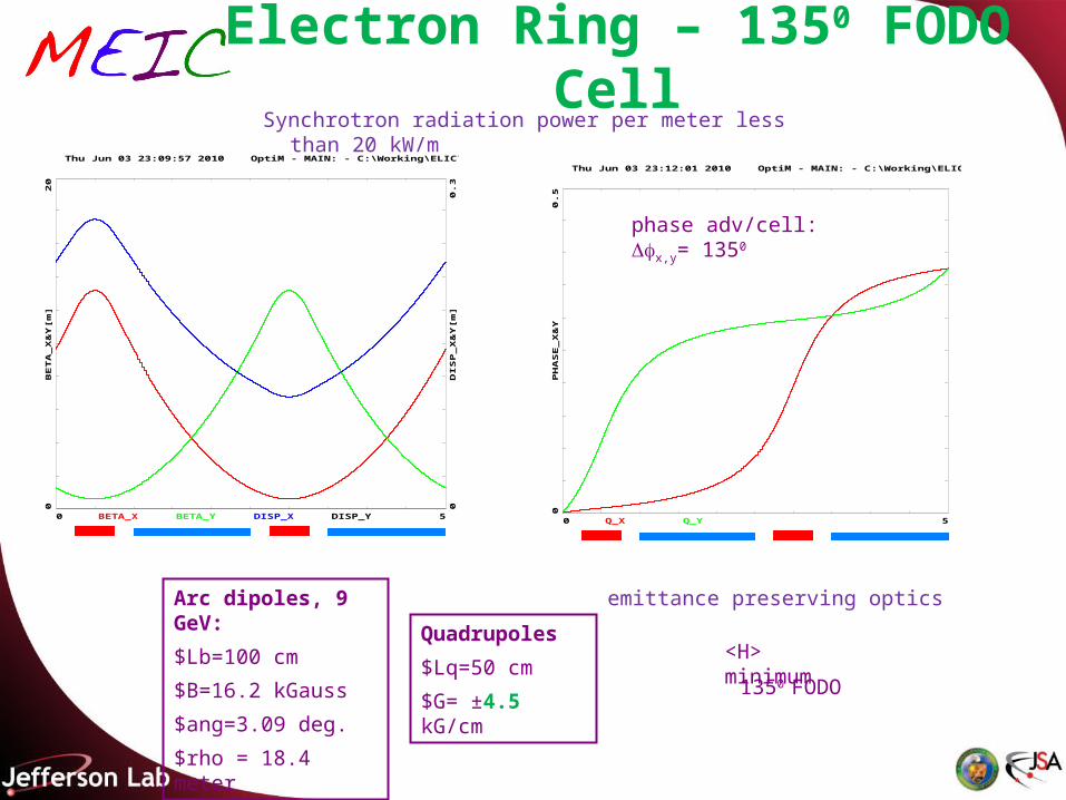
1350 FODO
Arc dipoles, 9 GeV:
$Lb=100 cm
$B=16.2 kGauss
$ang=3.09 deg.
$rho = 18.4 meter
<H> minimum
50
Thu Jun 03 23:09:57 2010 OptiM - MAIN: - C:\Working\ELIC\MEIC\Optics\Disp_Figure8_rel\Cell__135_in.opt
20
0
0.3
0
BE
TA
_X
&Y
[m]
DIS
P_
X&
Y[m
]
BETA_X BETA_Y DISP_X DISP_Y
Electron Ring – 1350 FODO Cell
50
Thu Jun 03 23:12:01 2010 OptiM - MAIN: - C:\Working\ELIC\MEIC\Optics\Disp_Figure8_rel\Cell__135_in.opt
0.5
0P
HA
SE
_X
&Y
Q_X Q_Y
Synchrotron radiation power per meter less than 20 kW/m
emittance preserving optics
Quadrupoles
$Lq=50 cm
$G= ±4.5 kG/cm
phase adv/cell: x,y= 1350
2440
Thu Jun 03 23:33:16 2010 OptiM - MAIN: - C:\Working\ELIC\MEIC\Optics\Disp_Figure8_rel\Arc_str_Arc.opt
20
0
0.3
0
BE
TA
_X
&Y
[m]
DIS
P_
X&
Y[m
]
BETA_X BETA_Y DISP_X DISP_Y
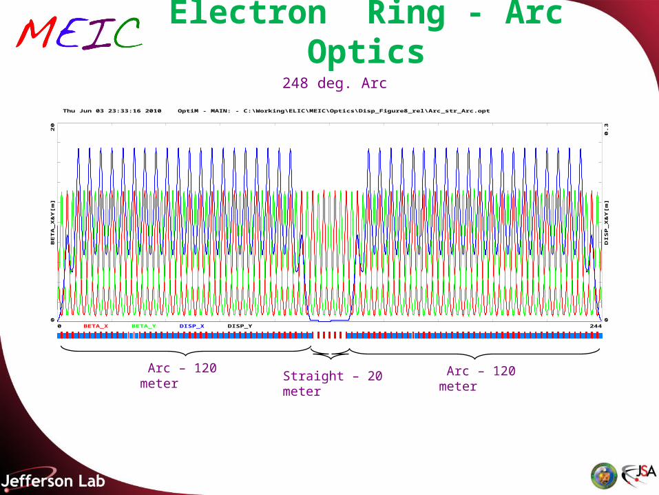
Electron Ring - Arc Optics
Straight – 20 meter Arc – 120 meter
248 deg. Arc
Arc – 120 meter
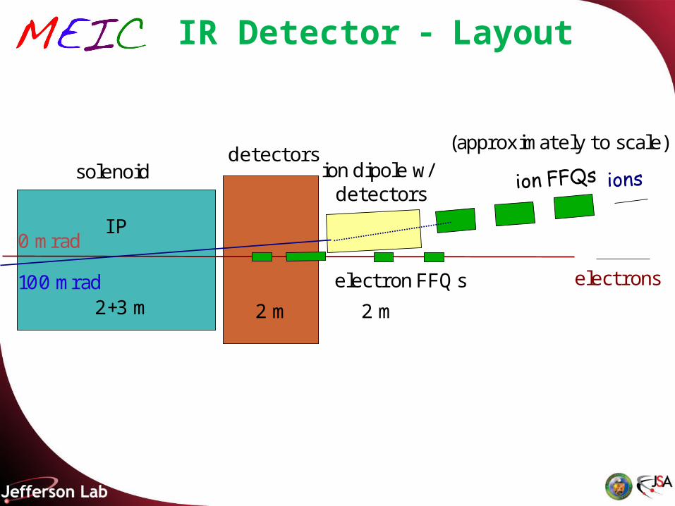
IR Detector Layout
solenoid
electron FFQs100 mrad
0 mrad
ion dipole w/ detectors
(approximately to scale)
electrons
I P
detectors
2+3 m 2 m 2 m
IR Optics (electrons)
2 1
* *IR
f f
f
Natural Chromaticity:
x = -47 y = -66
190
800
0
50
BE
TA
_X&
Y[m
]
DIS
P_X
&Y
[m]
BETA_X BETA_Y DISP_X DISP_Y
*
*
10
2
x
y
cm
cm
l * = 3.5m
IP
FF doublets
f
*2 2
* 223.5
6 102 10
ff m
2*
*( )
max0FFg
IR Optics (electrons at 5 GeV)6
6
22 10
4.4 10
xN
yN
m
m
*
*
10
2
x
y
cm
cm
Q4 Q3 Q2 Q1 Q1 G[kG/cm] = -2.8Q2 G[kG/cm] = 3.1Q3 G[kG/cm] = -2.0Q4 G[kG/cm] = 2.0
* 6
* 6
15 10
3 10
x
y
m
m
190
0.15
0
0.15
0
Siz
e_X
[cm
]
Siz
e_Y
[cm
]
Ax_bet Ay_bet Ax_disp Ay_disp
IP
*( ) N
IP
190
800
0
50
BE
TA
_X&
Y[m
]
DIS
P_X
&Y
[m]
BETA_X BETA_Y DISP_X DISP_Y
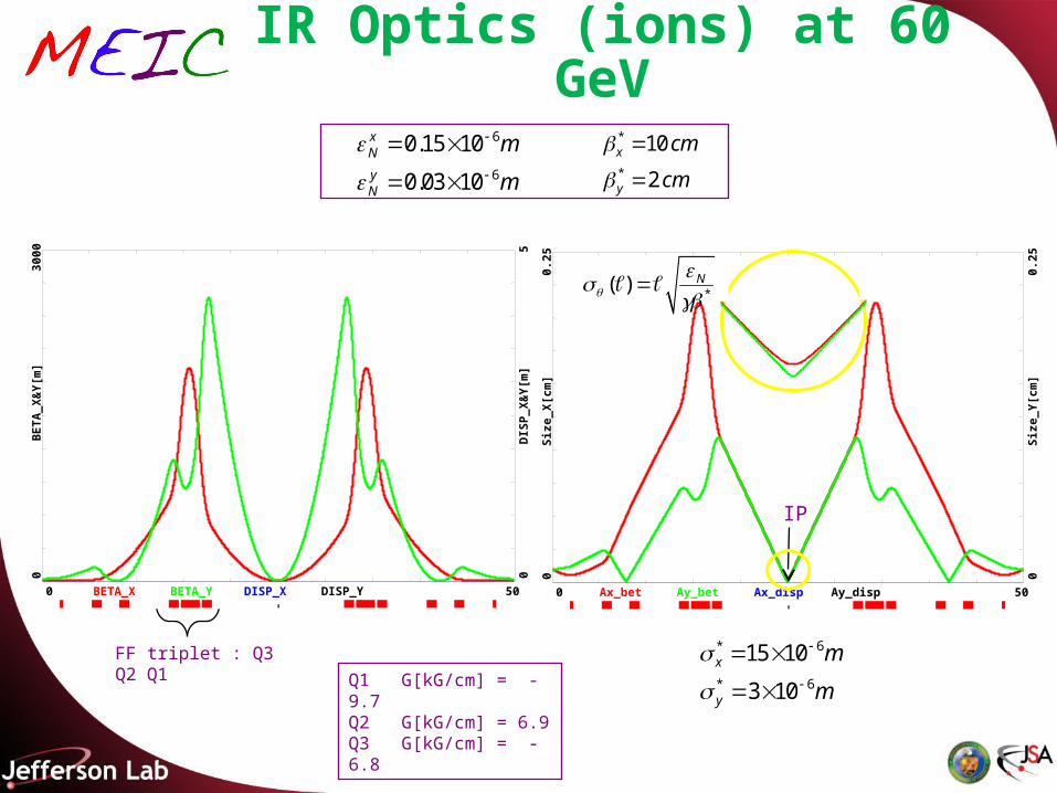
IR Optics (ions)
2 1
* *IR
f f
f
Natural Chromaticity: x = -88 y = -141
500
3000
0
50
BE
TA
_X&
Y[m
]
DIS
P_X
&Y
[m]
BETA_X BETA_Y DISP_X DISP_Y
l * = 7m
IP
FF triplet : Q3 Q2 Q1
f
*3
*2 2
2
7
2 12.
05 10ff m
2
**
( )
*
*
10
2
x
y
cm
cm
max
0FFg
500
0.25
0
0.25
0
Siz
e_X
[cm
]
Siz
e_Y
[cm
]
Ax_bet Ay_bet Ax_disp Ay_disp
IR Optics (ions) at 60 GeV
IP
6
6
0.15 10
0.03 10
xN
yN
m
m
*
*
10
2
x
y
cm
cm
Q1 G[kG/cm] = -9.7Q2 G[kG/cm] = 6.9Q3 G[kG/cm] = -6.8
* 6
* 6
15 10
3 10
x
y
m
m
*( ) N
FF triplet : Q3 Q2 Q1
IP
500
3000
0
50
BE
TA
_X&
Y[m
]
DIS
P_X
&Y
[m]
BETA_X BETA_Y DISP_X DISP_Y
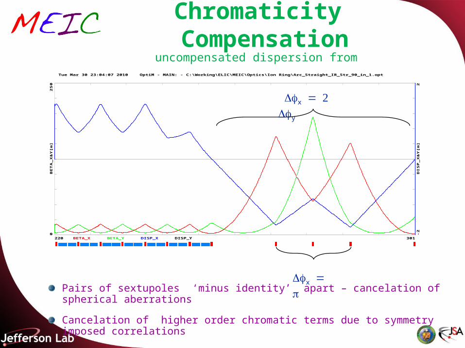
Chromaticity Compensationuncompensated dispersion from the Arc
301220
Tue Mar 30 23:04:07 2010 OptiM - MAIN: - C:\Working\ELIC\MEIC\Optics\Ion Ring\Arc_Straight_IR_Str_90_in_1.opt
25
00
2-2
BE
TA
_X
&Y
[m]
DIS
P_
X&
Y[m
]
BETA_X BETA_Y DISP_X DISP_Y
x
y
xPairs of sextupoles ‘minus identity’ apart – cancelation of spherical aberrations
Cancelation of higher order chromatic terms due to symmetry imposed correlations
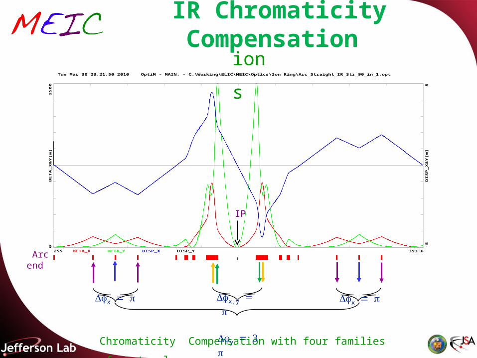
IR Chromaticity Compensation
Chromaticity Compensation with four families of sextupoles
393.6255
Tue Mar 30 23:21:50 2010 OptiM - MAIN: - C:\Working\ELIC\MEIC\Optics\Ion Ring\Arc_Straight_IR_Str_90_in_1.opt
25
00
0
5-5
BE
TA
_X
&Y
[m]
DIS
P_
X&
Y[m
]
BETA_X BETA_Y DISP_X DISP_Y
x
x
x,y y
IP
Arc end
ions
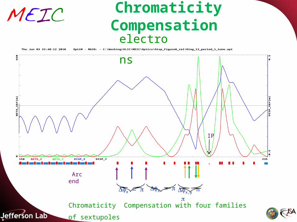
Chromaticity Compensation
Chromaticity Compensation with four families of sextupoles
235150
Thu Jun 03 23:40:12 2010 OptiM - MAIN: - C:\Working\ELIC\MEIC\Optics\Disp_Figure8_rel\Ring_13_period_1_tune.opt
65
00
0.5
-0.5
BE
TA
_X
&Y
[m]
DIS
P_
X&
Y[m
]
BETA_X BETA_Y DISP_X DISP_Y
x
x,y
IP
Arc end x
electrons
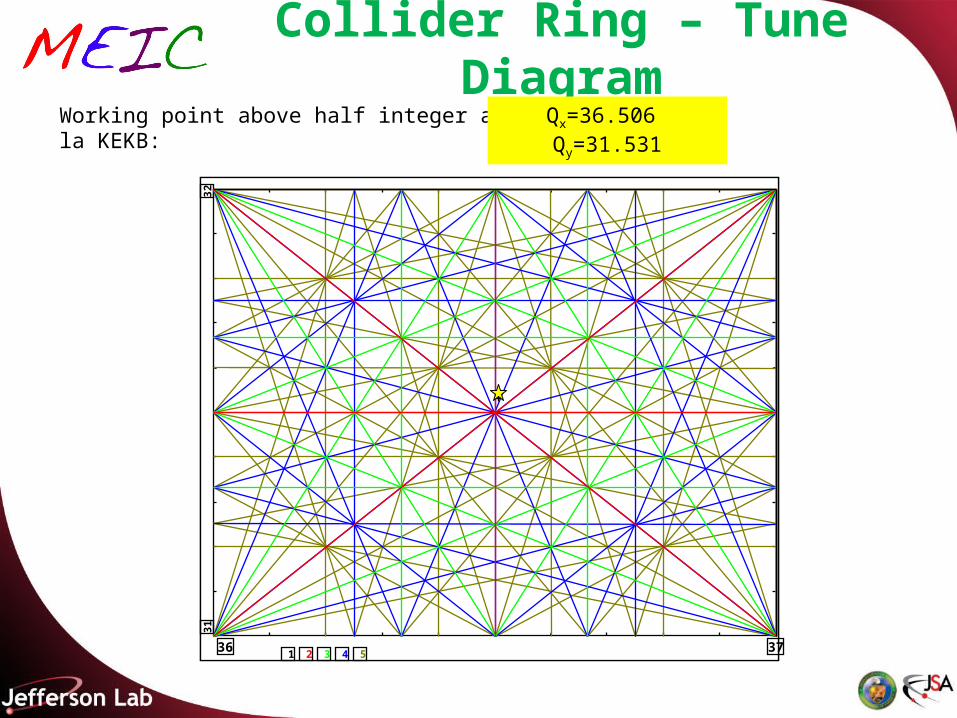
Collider Ring – Tune DiagramWorking point above half integer a la KEKB: Qx=36.506 Qy=31.531
3736
3231
5 4 3 2 1
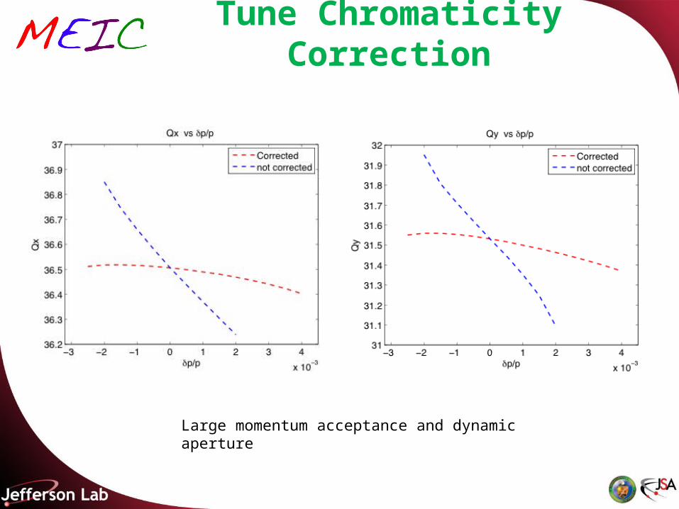
Tune Chromaticity Correction
Large momentum acceptance and dynamic aperture
total ring circumference: 1000 m
-10000
-8000
-6000
-4000
-2000
0
2000
4000
6000
8000
10000
-20000 -15000 -10000 -5000 0 5000 10000 15000 20000x [cm]
z [cm]
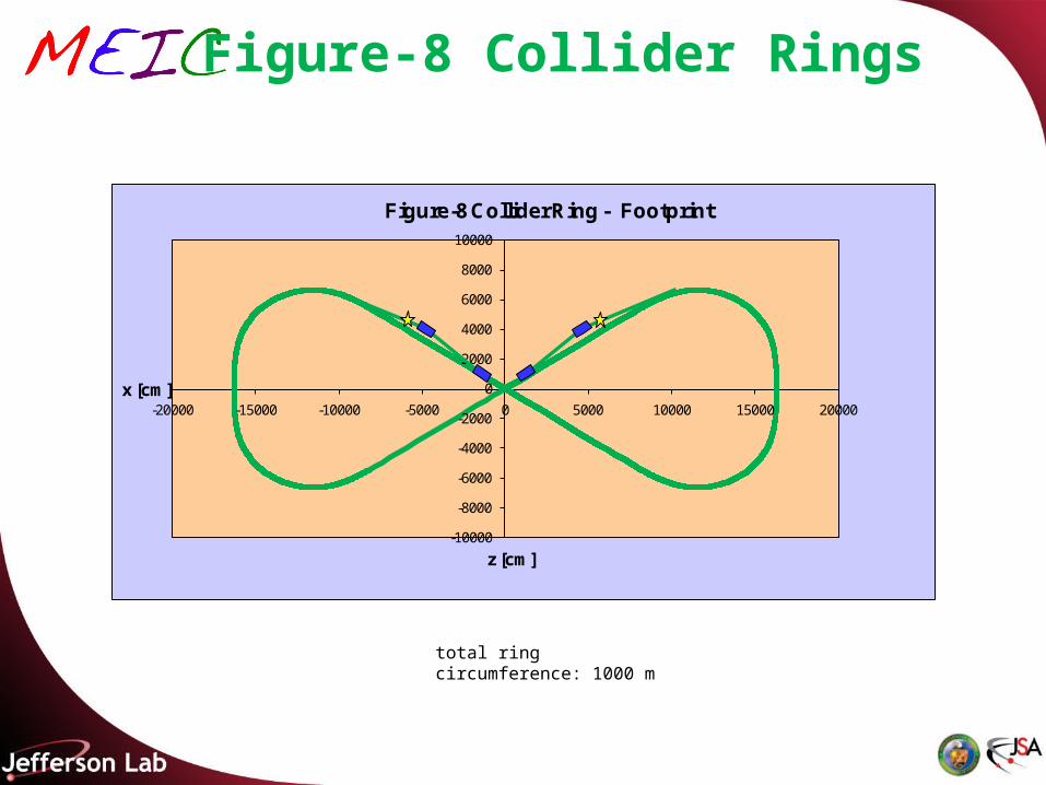
Figure-8 Collider Ring - Footprint
Figure-8 Collider Rings

Figure-8 Collider Rings
total ring circumference: 1000 m
-10000
-8000
-6000
-4000
-2000
0
2000
4000
6000
8000
10000
-20000 -15000 -10000 -5000 0 5000 10000 15000 20000x [cm]
z [cm]
Figure-8 Collider Ring - Footprint
Summary
MEIC EIC at JLab promises to accelerate and store a wide variety of polarized light ions and un-polarized heavy ions in collision with polarized electron or positron beam enabling a unique physics program.
The project covers a wide CM energy range (10 to 100 GeV) in a coherent way. In the immediate future, a low-to-medium energy collider (CM energy 10 to 50 GeV) is our immediate goal & R&D focus.
The collider luminosity for e-p collisions should reach ~1034 cm-2s-1 at (60x3~52 GeV2)
The project is now based on mostly proven accelerator technologies. Making a high intensity ion beam with high repetition rate, small emittance and short bunch length is a key to reaching the luminosity goals (advanced cooling techniques are required).
We have identified critical accelerator R&D topics for the project, We are currently pursuing staged accelerator design studies to validate and further optimize our design.