accelerating scientific applications with high … · accelerating scientific applications with...
TRANSCRIPT

Accelerating Scientific Applications
with High-Performance
Reconfigurable Computing (HPRC)
Volodymyr V. Kindratenko
Innovative Systems Laboratory (ISL)
National Center for Supercomputing Applications (NCSA)
University of Illinois at Urbana-Champaign (UIUC)
National Center for Supercomputing Applications

Presentation Outline
• Motivation
• Reconfigurable computing technology background
– FPGA, dataflow graph, FPGA “code” design cycle, HPRC
systems/design flow
• HPRC Application Design Issues
– SW/HW code partitioning, code transformations, performance
measurements, load-balancing
• HPC Application examples
– Molecular dynamics
– Cosmology
• Conclusions
National Center for Supercomputing Applications

NCSA Production HPC Systems
• Dell Intel® 64 Linux Cluster [abe]
– Dell blade system with 1,200 PowerEdge 1955 dual socket, quad core compute blades, an
InfiniBand interconnect and 100 TB of storage in a Lustre filesystem.
– Peak performance: 88.3 TF
– Top 500 list debut: #8 (June 2007)
• Dell Blade system [t3]
– 1,040 dual-core Intel 2.66 GHz processors an InfiniBand interconnect, 4.1 terabytes of total
memory, and a 20 terabyte Lustre filesystem.
– Peak performance: 22.1 TF
• Dell Xeon Cluster [tungsten]
– 2,560 Intel IA-32 Xeon 3.2 GHz processors, 3 GB memory/node
– Peak performance: 16.38 TF (9.819 TF sustained)
– Top 500 list debut: #4 (November 2003)
• IBM IA-64 Linux Cluster [mercury]
– 1,774 Intel Itanium 2 1.3/1.5 GHz processors, 4 GB and 12 GB memory/node
– Peak performance: 10.23 TF (7.22 TF sustained)
– Top 500 list debut: #15 (June 2004)
• SGI Altix [cobalt]
– 1,024 Intel Itanium 2 processors
– Peak performance: 6.55 TF (6.1 TF sustained)
– Top 500 list debut: #48 (June 2005)
• IBM pSeries 690 [copper]
– 384 IBM POWER4 p690 processors, 7 with 64 GB/system, 4 with 256 GB/system
– Peak performance: 2 TF (708 GF sustained)
– Top 500 list debut: #99 (June 2003)
National Center for Supercomputing ApplicationsSource: http://www.ncsa.uiuc.edu/UserInfo/Resources/Hardware/

HPC Challenges
• Computational complexity of scientific applications increases faster than the
hardware capabilities used to run the applications
– Science and engineering teams are requesting more cycles than HPC centers can provide
• The gap between the application performance and the peak system performance
increases
– Few applications can utilize high percentage of microprocessor peak performance, but even
fewer applications can utilize high percentage of the peak performance of a multiprocessor
system
• I/O bandwidth and clock wall put limits on computing speed
– Computational speed increasing faster than memory or network latency is decreasing
– Computational speed is increasing faster than memory bandwidth
– The processor speed is limited due to leakage current
– Storage capacities increasing faster than I/O bandwidths
• Building and using larger machines becomes more and more challenging
– Increased space, power, and cooling requirements• ~$1M+ per year in cooling and power costs for moderate sized systems
– Application fault-tolerance becomes a major concern
National Center for Supercomputing Applications

Black Hole Collision Problem
National Center for Supercomputing Applications
1963
Hahn and Lindquist
IBM 7090
One Processor
Each 0.2 MF
3 Hours
1977
Eppley and Smarr
CDC 7600
One Processor
Each 35 MF
5 Hours
1999
Seidel and Suen, et al.
NCSA SGI Origin
256 Processors
Each 500 MF
40 Hours
300X 30,000X
1,800,000,000X
2001
Seidel et al
NCSA Pentium III
256 Processors
Each 1 GF
500,000 Hours total
plus 500,000 hours at NERSC
~200X
Processor speedup is only 5000x
(~50 KW)
Source: http://gladiator.ncsa.uiuc.edu/PDFs/iacat/Pennington_PetascaleSystems_Apr06.pdf

Digit{ized|al} Sky Surveys
From Data Drought to Data Flood
National Center for Supercomputing Applications
1977-1982
First CfA Redshift Survey
spectroscopic observations of
1,100 galaxies
1985-1995
Second CfA Redshift Survey
spectroscopic observations of
18,000 galaxies
Sources: http://www.cfa.harvard.edu/~huchra/zcat/
http://www.sdss.org/
2000-2005
Sloan Digital Sky Survey I
spectroscopic observations of
675,000 galaxies

New Ways of Computing
• General-purpose processors
– Multi-core
• Special-purpose processors
– Field-Programmable Gate Arrays
(FPGAs)
• Digital signal processing, embedded
– Graphics Processing Units (GPUs)
• Desktop graphics accelerators
– Sony/Toshiba/IBM Cell Broadband
Engine
• Game console and digital content delivery
systems
– …National Center for Supercomputing Applications

High-Performance Reconfigurable
Computing (HPRC)
• Gerald Estrin's idea of “fixed plus
variable structure computer”
– reconfigurable hardware is tailored to
perform a specific task
• as quickly as a dedicated piece of
hardware
– once the task is done, the hardware is
adjusted to do other tasks
– the main processor controls the behavior
of the reconfigurable hardware
• Wikipedia‟s definition
– “Reconfigurable computing is computer
processing with highly flexible computing
fabrics. The principal difference when
compared to using ordinary
microprocessors is the ability to make
substantial changes to the data path itself
in addition to the control flow.”
• Field Programmable Gate Array
(FPGA) is the enabling technology
• IEEE Computer, March 2007
• High-Performance Reconfigurable Computers are
parallel computing systems that contain multiple
microprocessors and multiple FPGAs. In current
settings, the design uses FPGAs as coprocessors that
are deployed to execute the small portion of the
application that takes most of the time—under the 10-
90 rule, the 10 percent of code that takes
90 percent of the execution time.
National Center for Supercomputing Applications

Reconfigurable Computing (RC)
Promises
• Higher sustained performance
– exploring inherent parallelism in
algorithms
• spatial parallelism, instruction level
parallelism
– matching computation with data flow
• FPGAs are on a faster „growth‟
curve than CPUs
– Can keep up with the increasing
complexity of scientific applications
• Reduced power requirements as
compared to microprocessor-based
systems
– Larger systems can be built
• Faster execution, better resource
utilization, and lower power
consumption
and Pitfalls
• Current FPGA technology does not
address the needs of scientific
computing community
– Gate count on FPGAs only recently
became sufficient for practical use in
applications with DPFP
– No dedicated FP hardware support
• Software development for RC
systems by computational
scientists still remains not easy
– Software development methodology for
RC is different from software
development methodology for
microprocessor-based systems
National Center for Supercomputing Applications

Motivation
• Can Reconfigurable Computing be used to accelerate computationally
intensive scientific applications?
– Speedup of an order of magnitude or more
– Codes that rely on double-precision floating-point math
• Can computational scientists effectively use Reconfigurable Computing
without the need to re-write all their code from scratch?
– Reuse of legacy code is important
• Can computational scientists effectively use Reconfigurable Computing
without the need to become hardware experts?
– C/Fortran style of code development as opposite to hardware design tools and
hardware description languages
• Is this technology viable today and will it be viable in 5, 10 years from
now?
– Technology development roadmap
– FPGA performance trends vs. multi-core CPU performance trend
National Center for Supercomputing Applications

Presentation Outline
• Motivation
• Reconfigurable computing technology background
– FPGA, dataflow graph, FPGA “code” design cycle, HPRC
systems/design flow
• HPRC Application Design Issues
– SW/HW code partitioning, code transformations, performance
measurements, load-balancing
• HPC Application examples
– Molecular dynamics
– Cosmology
• Conclusions
National Center for Supercomputing Applications

National Center for Supercomputing Applications
Generic FPGA Structure
• FPGAs are
– small clusters of “low-level”
logic, e.g.,
• flip-flops
• lookup tables (LUTs)
– and connection grids
– that can be reconfigured to
implement “higher-level”
operations
• “Bitstream” is a
complete configuration
for the chip
switch blockfunction block
I/O block interconnect

National Center for Supercomputing Applications
Example: Xilinx Virtex 2 FPGAs
• Virtex-II XC2V6000
– 33,792 slices
• 67,584 4-input LUTs
• 67,584 flip flops
– 144 18x18 integer multipliers
– 144 Block RAMs (2,592 Kbits total)
– 1,104 User I/O
• Virtex 2 Pro 2VP100
– 44,096 slices
• 88,192 4-input LUTs
• 88,192 flip flops
– 444 18x18 integer multipliers
– 444 Block RAMs (7,992 Kbits total)
– 1,164 User I/O
– 20 RocketIO Transceivers
– 2 PPC405s

National Center for Supercomputing Applications
Configurable Logic Blocks (CLB) slice
• Main elements
are
– lookup tables &
– flip-flops
• Configurable
refers to the
ability to load
lookup tables
with user-
specified logic

National Center for Supercomputing Applications
Lookup tables (LUT)
• Lookup tables
are primary
elements for
logic
implementation
• Each LUT can
implement any
function of 4
inputs

National Center for Supercomputing Applications
Implementing Operations on FPGA
• Example: adder
– Described by a HDL (VHDL
or Verilog)
– “Synthesized” to the “low-
level” resources available on
the chip
+ clock
16b 16b
16b

National Center for Supercomputing Applications
Dataflow Concept
• Basic idea
– express computation with
interconnected function units
• Data flow graph (DFG)
• Can be implemented in
FPGA logic
• Each function unit has a
latency
– If we provide inputs to the
DFG, the results will be
output n clock cycles later
– Thus, new inputs can be
taken every n clock cycles
A=B+C*D-E
C DB
+
x
E
-
A
2c
1c
1c
4c

National Center for Supercomputing Applications
Pipelining Concept
• Basic idea– Non-pipelined functional
unit can take new inputs only after it is done processing previous inputs
– The fully pipelined functional unit can take a new input and produce a new output on every clock cycle
• DFG can be pipelined by adding delays
A=B+C*D-E
C DB
+
x
E
-
A
2c
1c
1c
4c
2c
3c

National Center for Supercomputing Applications
Examples of Pipelined DFGs
for (i=0; i<n; i++)
a[i]=b[i]*c[i]
if (a>b) c = a+b;
else c = a*b;
&a &b &c
i
+++
load load
store
x
delay
delay
1c 1c 1c
3c 3c 3c
2c2c
3c
9c
a b
x+>
delay
selector
2c1c1c
1cdelay 1c
3c
1c

National Center for Supercomputing Applications
Traditional FPGA “Code” Design Cycle
Algorithm
HDL Model
netlist
bitstream
synthesis
implementation (map, place & route)
Functional simulation
Post-synthesis simulation
Timing simulation
downloading and testing

National Center for Supercomputing Applications
Mapping
LUT 1 LUT 2
LUT 3
LUT 4
netlist

National Center for Supercomputing Applications
FPGA
CLB slices
Placing
LUT 1 LUT 2
LUT 3LUT 4
netlist

National Center for Supercomputing Applications
Routing
FPGA
CLB slices
LUT 1 LUT 2
LUT 3LUT 4
netlist

National Center for Supercomputing Applications
P&R Report Example
• Device Utilization Summary
Number of BUFGMUXs 1 out of 16 6%
Number of External IOBs 815 out of 1104 73%
Number of LOCed IOBs 815 out of 815 100%
Number of MULT18X18s 10 out of 144 6%
Number of SLICEs 3286 out of 33792 9%
• Clock report
---------------------------------------------------------------------------
Constraint | Requested | Actual | Logic
| | | Levels
---------------------------------------------------------------------------
TS_CLOCK = PERIOD TIMEGRP "CLOCK" 10 ns H | 10.000ns | 9.786ns | 0
IGH 50% | | |
---------------------------------------------------------------------------

High-Level Language based FPGA Code Design
National Center for Supercomputing ApplicationsNational Center for Supercomputing Applications
Algorithm
HLL Model
HLL to HDL
compiler
Conventional software
execution and
debugging
Synthesis and
implementation
transparent to the
software developer bit
stre
am
downloading
and testing

National Center for Supercomputing Applications
HPRC System Concept Overview
• Microprocessor • Reconfigurable
processor
microprocessor FPGA
memorymemory
common
memory
communication channel (PCI, DIM, HyperTransport, etc.)
disk

SGI Altix 350 with RC100 Blade
dual-Itanium 2
motherboard
1.4 GHz, 4 GB memory
2 microprocessors
memory
NUMALink 4
3.2 GB/s
each direction
dual-blade chassis
RC100 blade 2RC100 blade 1
TIO ASIC
Loader
FPGA
PROM
QD
R S
RA
M
QD
R S
RA
M
QD
R S
RA
M
QD
R S
RA
M
QD
R S
RA
M
TIO ASIC
QD
R S
RA
M
QD
R S
RA
M
QD
R S
RA
M
QD
R S
RA
M
QD
R S
RA
M
Algorithm FPGA 1
Virtex 4 LX200
Algorithm FPGA 2
Virtex 4 LX200
3.2
GB
/s
each
dire
ctio
n
3.2
GB
/s
each
dire
ctio
n
1.6
GB
/s
each
dire
ctio
n

SCR-6 Reconfigurable Computer
dual-Xeon motherboard2.8 GHz, 1 GB memory
Memory
SRC Hi-Bar 4-port SwitchSustained 1.4 GB/s per port with 180 ns latency per tier
SNAP™
2 microprocessors
PCI-X
4.8 GB/s
2400 MB/s eachGPIO
4.8 GB/s
OBM A (4 MB)
OBM B (4 MB)
OBM C (4 MB)
OBM D (4 MB)
OBM E (4 MB)
OBM F (4 MB)
Control FPGA
User FPGA 1XC2VP100
User FPGA 0XC2VP100
192
64 6464646464
192
108
64 6464646464
OBM G (2 MB)
OBM H (2 MB)
1.4 GB/s1.4 GB/s MAPE®
Reconfigurable Processor
SRC-6 MAPstation

National Center for Supercomputing Applications
RC Software Development
HW/SW
partitioning
HW implementation,
test & verification
microprocessor code
SW implementation,
test & verification
FPGA design
algorithm
specifications
FPGA
platform
description
microprocessor
platform
description

Presentation Outline
• Motivation
• Reconfigurable computing technology background
– FPGA, dataflow graph, FPGA “code” design cycle, HPRC
systems/design flow
• HPRC Application Design Issues
– SW/HW code partitioning, code transformations, performance
measurements, load-balancing
• HPC Application examples
– Molecular dynamics
– Cosmology
• Conclusions
National Center for Supercomputing Applications

National Center for Supercomputing Applications
SW/HW Code Partitioning
• Code profiling is necessary to identify code
section(s) responsible for the majority of the
execution time
– 90% of time is spent while executing 10% of the code
• Other factors are important as well
– Process granularity
– Data conversion
– Number of calls to the FPGA-based code
V. Kindratenko, Code partitioning for reconfigurable high-performance computing: a case study,
in Proc. Engineering of Reconfigurable Systems and Algorithms - ERSA'06, 2006, pp. 143-149

National Center for Supercomputing Applications
Example: MATPHOT
• Image convolution using a separable
kernel
1
0
1
0
][][],[],[],[
k
i
col
l
j
row ihjhjnimalkhnma
1DCONVOLUTION(I, O, P, H, Q) 1 for p ← 0 to P-1 2 O[p] ← 0 3 for q ← 0 to Q-1 4 O[p] ← O[p] + I[p+q] · H[q] 5 end 6 return O

National Center for Supercomputing Applications
Image Convolution
• Per-row convolution
followed by per-
column convolution
• O(K+L) per-pixel
computational
complexity
=
=
K
L

National Center for Supercomputing Applications
Image Convolution Implementation
• Wrapper
/* shift DELTAX pixels in the X direction */
for (iy = 0; iy < image_in->sn; ++iy)
{
for (ix = 0; ix < image_in->sm; ++ix)
iAx[ix] = image_in->img[iy*image_in->sm+ix];
sshift(iAx, image_in->sm, dx, zeroF, oAx, sinc_x);
for (ix = 0; ix < image_out->sm; ++ix)
image_out->img[iy*image_out->sm+ix] = oAx[ix];
}
/* shift DELTAY pixels in the Y direction */
for (ix = 0; ix < image_in->sm; ++ix)
{
for (iy = 0; iy < image_in->sn; ++iy)
iAy[iy] = image_out->img[iy*image_in->sm+ix];
sshift(iAy, image_in->sn, dy, zeroF, oAy, sinc_y);
for (iy = 0; iy < image_out->sn; ++iy)
image_out->img[iy*image_out->sm+ix] = oAy[iy];
}
• Image occupies a continuous memory segment
• Subroutine
void sshift(float *x, long n, float shift, float hole, float *xp, float *sinc)
{
// split the desired shift into a fractional and integer part
int ishift = (int)shift;
float fshift = shift - ishift;
/* convolve the input data with the sinc array */
for (int point = 0; point < n; point++)
{
xp[point] = 0.0f;
for (int lobe = 0; lobe < 21; lobe++)
{
int npix = point - (lobe - 10);
if ( (npix >= 0) && (npix < n) ) {
xp[point] += sinc[lobe] * x[npix];
}
else {
xp[point] += sinc[lobe] * hole;
}
}
}
}
National Center for Supercomputing Applications
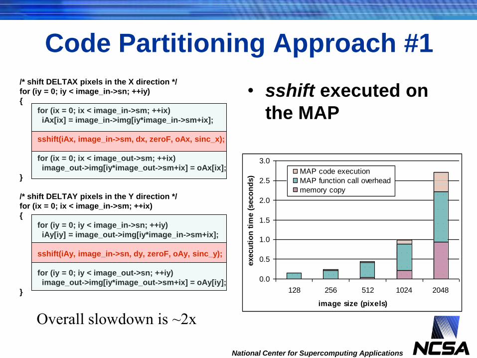
• sshift executed on
the MAP
Code Partitioning Approach #1
/* shift DELTAX pixels in the X direction */
for (iy = 0; iy < image_in->sn; ++iy)
{
for (ix = 0; ix < image_in->sm; ++ix)
iAx[ix] = image_in->img[iy*image_in->sm+ix];
sshift(iAx, image_in->sm, dx, zeroF, oAx, sinc_x);
for (ix = 0; ix < image_out->sm; ++ix)
image_out->img[iy*image_out->sm+ix] = oAx[ix];
}
/* shift DELTAY pixels in the Y direction */
for (ix = 0; ix < image_in->sm; ++ix)
{
for (iy = 0; iy < image_in->sn; ++iy)
iAy[iy] = image_out->img[iy*image_in->sm+ix];
sshift(iAy, image_in->sn, dy, zeroF, oAy, sinc_y);
for (iy = 0; iy < image_out->sn; ++iy)
image_out->img[iy*image_out->sm+ix] = oAy[iy];
}
0.0
0.5
1.0
1.5
2.0
2.5
3.0
128 256 512 1024 2048
image size (pixels)
execu
tio
n t
ime (
seco
nd
s)
MAP code execution
MAP function call overhead
memory copy
Overall slowdown is ~2x

National Center for Supercomputing Applications
• intp_filter1D
executed on the MAP
Code Partitioning Approach #2
/* shift DELTAX pixels in the X direction */
intp_filter1D((int64_t *)sinc_x, (int64_t *)image_in->img, (int64_t *)tmp1->img, image_in->sm, image_in->sn, hole, &tm1, mapnum);
// rotate image
pgm_turn(tmp1, image_out, LEFT);
/* shift DELTAY pixels in the Y direction */
intp_filter1D((int64_t *)sinc_y, (int64_t *)image_out->img, (int64_t *)tmp1->img, image_out->sm, image_out->sn, hole, &tm1, mapnum);
// rotate image
pgm_turn(tmp1, image_out, RIGHT);
0.0
0.5
1.0
1.5
2.0
2.5
3.0
128 256 512 1024 2048
image size (pixels)
execu
tio
n t
ime (
seco
nd
s)
MAP code execution
MAP function call overhead
memory copy
Overall slowdown is ~1.5x

National Center for Supercomputing Applications
• intp_filter2D
executed on the MAP
Code Partitioning Approach #3
/* 2D interpolation */
intp_filter2D((int64_t *)image_in->img,
(int64_t *) image_out->img,
(int)image_in->sm, (int)image_in->sn,
(int64_t *)sinc_x, (int64_t *)sinc_y, zeroF,
image_in->sm*image_in->sn*sizeof(float),
&tm, mapnum);
0.00
0.05
0.10
0.15
0.20
0.25
0.30
128 256 512 1024 1772
image size (pixels)
execu
tio
n t
ime (
seco
nd
s) MAP code execution
MAP function call overhead
Overall speedup is 3x

National Center for Supercomputing Applications
Comparison for a 1024x1024 Image
0
0.2
0.4
0.6
0.8
1
CPU only scheme #1 scheme #2 scheme #3
Implementation type
Execu
tio
n t
ime (
s)
MAP 'compute' timeMAP function call overheadCPU 'compute' timeCPU data manipulation time

Code Transformations
• Why
– Separate address space
– Different memory architecture with explicit memory control
– SW/HW HL Language differences
• How
– Transform data to fit into the FPGA-accessible memory architecture
– Add data transfer calls to the subroutine to be ported to FPGA
– Modify the ported subroutine for explicit use of on-board or on-chip memory
banks
– For optimal performance, modify the ported subroutine to avoid memory
bank conflicts, scalar and memory dependencies
– For optimal performance, overlap data transfer with calculations
– If space permits, instantiate multiple execution pipelines …
National Center for Supercomputing Applications
V. Kindratenko, C. Steffen, R. Brunner, Accelerating scientific applications with reconfigurable computing
getting started (with SRC-6), to appear in Computing in Science and Engineering, 2007.
V. Kindratenko, D. Pointer, D. Caliga, High-Performance Reconfigurable Computing
Application Programming in C, White Paper, January 2006

Example: Rational Function Evaluation
• Evaluate the following function for a
million values of x:
• C implementation is straightforward:
for (i = 0; i < sz; i++) {
const double x = X[i];
double P = p0 + x * (p1 + x * (p2 + x * (p3 + x * (p4 + x * p5))));
double Q = q0 + x * (q1 + x * (q2 + x * (q3 + x * (q4 + x * q5))));
R[i] = P / Q;
}
National Center for Supercomputing Applications
5432
0
5432
0
xq+xq+xq+xq+xq+q
xp+xp+xp+xp+xp+p=
Q(x)
P(x)=R(x)
54321
54321

main.c
Original#include <stdlib.h>
#define SZ 1048576
void ratval5(double *X, double *R, int sz);
int main (int argc, char *argv[])
{
double *X = (double *)malloc(SZ * sizeof(double));
double *R = (double *)malloc(SZ * sizeof(double));
for (int i = 0; i < SZ; i++) X[i] = rand();
ratval5(X, R, SZ);
free(X);
free(R);
}
Modified for SRC-6#include <stdlib.h>
#include <libmap.h>
#define SZ 1048576
void ratval5(double X[], double R[], int sz, int mapnum);
int main (int argc, char *argv[])
{
int nummap=0;
double *X = (double *)Cache_Aligned_Allocate(SZ * sizeof(double));
double *R = (double *)Cache_Aligned_Allocate(SZ * sizeof(double));
for (int i = 0; i < SZ; i++) X[i] = rand();
map_allocate(1);
ratval5(X, R, SZ, nummap);
map_free(1);
Cache_Aligned_Free((char*)X);
Cache_Aligned_Free((char*)R);
}
National Center for Supercomputing Applications

ratval5
ratval5.c (target: CPU)
void ratval5(double *X, double *R, int sz)
{
const float p0=0.434f;
const float p1=-0.3434f;
const float p2=3.4545f;
const float p3=-0.0045f;
const float p4=-22.344f;
const float p5=-0.4542f;
const float q0=0.595f;
const float q1=0.34152f;
const float q2=-1.4653f;
const float q3=3.2323f;
const float q4=0.67578f;
const float q5=0.112f;
int i;
ratval5.mc (target: FPGA)#include <libmap.h>
void ratval5(double X[], double R[], int sz, int mapnum)
{
OBM_BANK_A (AL, double, MAX_OBM_SIZE)
OBM_BANK_B (BL, double, MAX_OBM_SIZE)
OBM_BANK_C (CL, double, MAX_OBM_SIZE)
OBM_BANK_D (DL, double, MAX_OBM_SIZE)
const float p0=0.434f;
const float p1=-0.3434f;
const float p2=3.4545f;
const float p3=-0.0045f;
const float p4=-22.344f;
const float p5=-0.4542f;
const float q0=0.595f;
const float q1=0.34152f;
const float q2=-1.4653f;
const float q3=3.2323f;
const float q4=0.67578f;
const float q5=0.112f;
int i;
National Center for Supercomputing Applications

ratval5 (continued)
ratval5.c (target: CPU)
for (i = 0; i < sz; i++)
{
const double x = X[i];
double P = p0 + x * (p1 + x * (p2 + x * (p3 + x * (p4 + x * p5))));
double Q = q0 + x * (q1 + x * (q2 + x * (q3 + x * (q4 + x * q5))));
R[i] = P / Q;
}
}
ratval5.mc (target: FPGA)if (!sz) return;
DMA_CPU (CM2OBM, AL, MAP_OBM_stripe(1,"A,B"), X, 1, sz*8, 0);
wait_DMA (0);
for (i = 0; i < sz; i++)
{
const double x = (i % 2 == 0) ? AL[i/2] : BL[i/2];
double P = p0 + x * (p1 + x * (p2 + x * (p3 + x * (p4 + x * p5))));
double Q = q0 + x * (q1 + x * (q2 + x * (q3 + x * (q4 + x * q5))));
double val = P / Q;
if (i % 2 == 0) CL[i/2] = val;
else DL[i/2] = val;
}
DMA_CPU (OBM2CM, CL, MAP_OBM_stripe(1,"C,D"), R, 1, sz*8, 0);
wait_DMA (0);
}
National Center for Supercomputing Applications
2.1
GF
LO
Ps
1.0
5 G
FL
OP
s
Loop summary:
clocks per iteration: 1
pipeline depth: 170

ratval5 revised
DMA_CPU (CM2OBM, AL, MAP_OBM_stripe(1,"A,B"), X, 1, sz*sizeof(double), 0);
wait_DMA (0);
#pragma src parallel sections
{
#pragma src section
{
int i;
for (i = 0; i < sz/2; i++)
{
const double x = AL[i];
double P = p0 + x * (p1 + x * (p2 + x * (p3 + x * (p4 + x * p5))));
double Q = q0 + x * (q1 + x * (q2 + x * (q3 + x * (q4 + x * q5))));
put_stream_dbl(&S0, P / Q, 1);
}
}
#pragma src section
{
int i;
for (i = 0; i < sz/2; i++)
{
const double x = BL[i];
double P = p0 + x * (p1 + x * (p2 + x * (p3 + x * (p4 + x * p5))));
double Q = q0 + x * (q1 + x * (q2 + x * (q3 + x * (q4 + x * q5))));
put_stream_dbl(&S1, P / Q, 1);
}
}
#pragma src section
{
stream_dma_cpu_dual(&S0, &S1, STREAM_TO_PORT, CL, DMA_C_D, R, 1,
sz*sizeof(double));
}
}
• Main memory to OBM DMA
data transfer
• First compute engine
– Input: OBM A
– Output: stream
• Second compute engine
– Input: OBM B
– Output: stream
• FPGA to main memory DMA
data transfer
– Input: 2 internal streams
– Output: main system memory
National Center for Supercomputing Applications
4.2
GF
LO
Ps
2.1
GF
LO
Ps

National Center for Supercomputing Applications
• Microprocessor
• FPGA
Performance Measurements
pre-
processing
post-
processingmicroprocessor compute engine
pre-
processing
post-
processing
DMA
data in
DMA
data out
FPGA
compute engine
Load
FPGA
overall compute time
kernel compute time
kernel compute time
kernel compute and FPGA overhead time
overall compute time
V. Kindratenko, D. Pointer, D. Caliga, High-Performance Reconfigurable Computing
Application Programming in C, White Paper, January 2006.

National Center for Supercomputing Applications
Example: Image Distance Transform
• For all background pixels, calculate the
distance to the nearest object
distance transform
bf

National Center for Supercomputing Applications
Brute Force Implementation
• Algorithm– Image pixels are divided into
foreground and background pixels
– Coordinate lists are built for each group of pixels
– For each pixel from the background list, calculate distance to each pixel from the foreground list and pick the shortest one
• Computational complexity is N*M where– N is number of the foreground
pixels
– M is number of the background pixels
// computational kernel
void dtransform_sw(short *fg_pixel, short *bg_pixel, float *bg_distance, long fg_count, long bg_count)
{
long i, j, d, d_min;
int x, y, dx, dy;
for (i = 0; i < 2*bg_count; i += 2)
{
x = bg_pixel[i];
y = bg_pixel[i+1];
d_min = MAX_INT;
for (j = 0; j < 2*fg_count; j += 2)
{
dx = x - fg_pixel[j];
dy = y - fg_pixel[j+1];
d = dx * dx + dy * dy;
if (d < d_min) d_min = d;
}
bg_distance[i/2] = sqrt(d_min);
}
}

National Center for Supercomputing Applications
SRC-6 Algorithm Implementationstart
DMA foreground pixels to OBM
DMA background pixels to OBM
stop
copy foreground pixels to BRAM
compute loop
20 distances at once
DMA results out
send to bridge initial parameters
fix for memory boundary alignment copy foreground pixels to BRAM
start
stop
get initial parameters from bridge
compute loop
20 distances at once
fix for memory boundary alignment
A B C D
A B
C D
bridge
DMA
DMA
DMA
E F
E F

National Center for Supercomputing Applications
Distance Compute Time OnlyMAP vs CPU performance (512x512 image)
18.118.919.519.9
17.818.4
0
10
20
30
40
50
60
70
1.0E+07 2.0E+09 4.0E+09 6.0E+09 8.0E+09 1.0E+10 1.2E+10 1.4E+10 1.6E+10
number of distance calculations
tim
e (
s)
0.0
5.0
10.0
15.0
20.0
sp
ee
d-u
p (
x)
CPU
MAP
speed-up

National Center for Supercomputing Applications
Overall Function Call TimeMAP vs CPU performance (512x512 image)
3.0
5.0
8.6
0.9
1.5
17.113.7
15.7
16.8 17.0
0
10
20
30
40
50
60
70
1.0E+07 2.0E+09 4.0E+09 6.0E+09 8.0E+09 1.0E+10 1.2E+10 1.4E+10 1.6E+10
number of distance calculations
tim
e (
s)
0.0
5.0
10.0
15.0
20.0
sp
ee
d-u
p (
x)
CPU
MAP
speed-up

National Center for Supercomputing Applications
Performance Analysis
• 200 foreground pixels
– ~55M distance calculations
– 1.5x speedup
– 0.15 sec FPGA function call
• 20,000 foreground pixels
– ~5B distance calculations
– 16.8x speedup
– 1.35 sec FPGA function call
data transfer,
0.0015, 0%
overhead,
0.1373, 10%
compute,
1.2107, 90%
compute,
0.0131, 9%
overhead,
0.1375, 90%
data transfer,
0.0016, 1%

Presentation Outline
• Motivation
• Reconfigurable computing technology background
– FPGA, dataflow graph, FPGA “code” design cycle, HPRC
systems/design flow
• HPRC Application Design Issues
– SW/HW code partitioning, code transformations, performance
measurements, load-balancing
• HPC Application examples
– Molecular dynamics
– Cosmology
• Conclusions
National Center for Supercomputing Applications

HPC Application Example 1: NAMD
• A parallel molecular dynamics code designed for high-performance simulation of large biomolecular systems
– 100K atoms on
– 100s of CPUs
• Developed by the Theoretical and Computational Biophysics Group at Beckman Institute, UIUC
• Currently is the largest compute cycle user on NCSA‟s production systems
National Center for Supercomputing Applications
First-Ever Simulation of Functioning Organism Spawned by
Ingenuity of Illinois Researchers and Power of SGI Altix,
SGI Press Release, May 2006.
Image is courtesy of Anton Arkhipov, UIUC Theoretical and
Computational Biophysics Group

National Center for Supercomputing Applications
Molecular Dynamics Simulation
• Basic principles
– each atom is treated as
a point mass
– simple force rules
describe the
interactions between
atoms
– Newton's equations are
integrated to move the
atoms
xi
xj
2
2
1
x)x(F
)x,x(f:)x(F
dt
dm i
ii
N
ji
jii

National Center for Supercomputing Applications
Molecular Dynamics Simulation
initialize
calculate forces
update positions
• Basic algorithm
))x(F(xx
)x,x(f:)x(F
x
1
1
ki
ki
ki
N
ji
kj
ki
ki
ki
f
time step
atom index

National Center for Supercomputing Applications
NAMD Benchmark Dataset
• 92224 atoms
• 144 patches
– between 500 and 700 atoms per patch
• numSelfComputes = 144
• numPairComputes = 144*13=1872
• calc_both() is called 144+1872=2016 times
• accumulated compute time is ~9.28 seconds
– SRC host workstation
• Dual Xeon 2.8 GHz, 1 GB mem

National Center for Supercomputing Applications
NAND on SRC MAP
• Steps necessary to port NAMD to SRC-6
– All data structures need to be converted to 1D
arrays
• lookup tables
• input data (atom position, etc.)
• output data (forces)
– The code to be ported to FPGA should be
outsourced to a separate function
• and modified to work with the 1D arrays

National Center for Supercomputing Applications
NAMD SRC-6 implementation
first time
start
DMA lookup tables to OBM
stream input data and copy to
OBM, BRAM, and stream to bridge
stop
yes no
copy lookup tables to BRAM
compute
for i=0,4,8,…
merge results and stream them out
send to bridge initial parameters
compute
for i=1,5,9,…
copy lookup tables to BRAM
copy from bridge to BRAM
first time
start
yes no
stop
get initial parameters from bridge
compute
for i=2,6,10,…
compute
for i=3,7,11,…
A B C D E F
A B
C D E F
bridge
bridge
A B
DMA
DMA
DMA
National Center for Supercomputing Applications
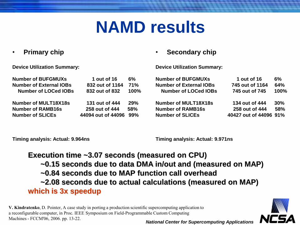
NAMD results
• Primary chip
Device Utilization Summary:
Number of BUFGMUXs 1 out of 16 6%
Number of External IOBs 832 out of 1164 71%
Number of LOCed IOBs 832 out of 832 100%
Number of MULT18X18s 131 out of 444 29%
Number of RAMB16s 258 out of 444 58%
Number of SLICEs 44094 out of 44096 99%
Timing analysis: Actual: 9.964ns
• Secondary chip
Device Utilization Summary:
Number of BUFGMUXs 1 out of 16 6%
Number of External IOBs 745 out of 1164 64%
Number of LOCed IOBs 745 out of 745 100%
Number of MULT18X18s 134 out of 444 30%
Number of RAMB16s 258 out of 444 58%
Number of SLICEs 40427 out of 44096 91%
Timing analysis: Actual: 9.971ns
Execution time ~3.07 seconds (measured on CPU)
~0.15 seconds due to data DMA in/out and (measured on MAP)
~0.84 seconds due to MAP function call overhead
~2.08 seconds due to actual calculations (measured on MAP)
which is 3x speedup
V. Kindratenko, D. Pointer, A case study in porting a production scientific supercomputing application to
a reconfigurable computer, in Proc. IEEE Symposium on Field-Programmable Custom Computing
Machines - FCCM'06, 2006. pp. 13-22.

HPC Application Example 2: Two-point
Angular Correlation
• TPACF, denoted as (), is the
frequency distribution of angular
separations between celestial
objects in the interval (, + )
– is the angular distance between
two points
• Red Points are, on average,
randomly distributed, black
points are clustered
– Red points: ()=0
– Black points: ()>0
• Can vary as a function of angular
distance, (blue circles)
– Red: ()=0 on all scales
– Black: () is larger on smaller
scales
National Center for Supercomputing Applications

National Center for Supercomputing Applications
The Method
• The angular correlation function is calculated
using the estimator derived by Landy & Szalay
(1993):
• where DD() and RR() are the autocorrelation
function of the data and random points,
respectively, and DR() is the cross-correlation
between the data and random points.
1
1
21
2
2
i
R
i
RDD
RRn
DRnn
DDn

National Center for Supercomputing Applications
DD & RR Algorithm: Autocorrelation
distancebin map
f()
bin
update
i: 0 to N-2 j: i+1 to N-1
N points
DD
(),
RR
()

National Center for Supercomputing Applications
DR Algorithm: Cross-correlation
distancebin map
f()
bin
update
i: 0 to N-1
j: 0 to N-1
N points
DR
()

National Center for Supercomputing Applications
Microprocessor Code Organization
// compute DD
doCompute{CPU|FPGA}(data, npd, data, npd, 1, DD, binb, nbins);
// loop through random data files
for (i = 0; i < random_count; i++)
{
// compute RR
doCompute{CPU|FPGA}(random[i], npr[i], random[i], npr[i], 1, RRS, binb, nbins);
// compute DR
doCompute{CPU|FPGA}(data, npd, random[i], npr[i], 0, DRS, binb, nbins);
}
// compute w
for (k = 0; k < nbins; k++)
{
w[k] = (random_count * 2*DD[k] - DRS[k]) / RRS[k] + 1.0;
}

Reference C Kernel Implementation
for (i = 0; i < ((autoCorrelation) ? n1-1 : n1); i++)
{
double xi = data1[i].x;
double yi = data1[i].y;
double zi = data1[i].z;
for (j = ((autoCorrelation) ? i+1 : 0); j < n2; j++)
{
double dot = xi * data2[j].x + yi * data2[j].y + * data2[j].z;
// binary search
min = 0; max = nbins;
while (max > min+1)
{
k = (min + max) / 2;
if (dot >= binb[k]) max = k;
else min = k;
};
if (dot >= binb[min]) data_bins[min] += 1;
else if (dot < binb[max]) data_bins[max+1] += 1;
else data_bins[max] += 1;
}
}National Center for Supercomputing Applications
pi
pj
q0 q1 q2 q3 q4 q5

Kernel Written in MAP C (SRC-6)
// main compute loop
for (i = 0; i < n1; i++) {
pi_x = AL[i]; pi_y = BL[i]; pi_z = CL[i]; // point i
#pragma loop noloop_dep
for (j = 0; j < n2; j++) {
// what bin memory bank to use in this loop iteration
cg_count_ceil_32 (1, 0, j == 0, 3, &bank);
pj_x = DL[j]; pj_y = EL[j]; pj_z = FL[j]; // point j
dot = pi_x * pj_x + pi_y * pj_y + pi_z * pj_z; // dot product
// find what bin it belongs to
select_pri_64bit_32val( (dot < bv31), 31, (dot < bv30), 30,
…
(dot < bv02), 2, (dot < bv01), 1, 0, &indx);
// update the corresponding bin count
if (bank == 0) bin1a[indx] += 1;
else if (bank == 1) bin2a[indx] += 1;
else if (bank == 2) bin3a[indx] += 1;
else bin4a[indx] += 1;
}
}National Center for Supercomputing Applications
Algorithm FPGA 2
OBM D
LS
OBM E OBM F
OBM B OBM COBM A
Algorithm FPGA 1
LS

Kernel Written in Mitrion-C (RC100)
// loop in one data set
(bins, afinal, bfinal) = for (i in <0 .. NPOINTS_1>)
{
(xi, yi, zi, a1, b1) = readpoint(a0, b0, i); // read next point
uint:64[NBINS] binsB = binsA;
ExtRAM a2 = a0;
ExtRAM b2 = b0;
(binsA, a3, b3) = for(j in <0 .. NPOINTS_1>)
{
(xj, yj, zj, a2, b2) = readpoint(a1, b1, j+NPOINTS); // read next point
float:53.11 dot = xi * xj + yi * yj + zi * zj; // compute dot product
int:8 indx = findbin(dot, binb); // find what bin it belongs to
// update bin
binsB = foreach (bin in binsB by ind) if (ind == indx) bin + 1 else bin;
} (binsB, a2, b2);
} (binsA, a3, b3);
National Center for Supercomputing Applications
Algorithm FPGA
SRAM 1 SRAM 2
LS

Performance on Different Platforms
• ~100,000 data points, 100 random files
National Center for Supercomputing Applications
Measured features/
parameters
SRC-6 host2.8 GHz Xeon
SRC-6 dual-
MAP
SGI Altix host1.4 GHz Itanium 2
RC100 blade
# CPUs 2 2
# FPGAs 4 2
# of compute
engines
1 17 2 4
DD time (s) 219.5 3 226.6 49.7
DR+RR time (s) 84,354.3 880.3 47,598.6 4,975.3
Load/convert (s) 20.3 20.7 28.4 27.5
Total (s) 84,594.1 904 47,853.6 5,052.5
Overall
Speedup1.0
93.5x(1)
52.9x1.0
9.5x(2)
(1) V. Kindratenko, R. Brunner, A. Myers, Dynamic load-balancing on multi-FPGA systems: a case study,
In Proc. 3rd Annual Reconfigurable Systems Summer Institute - RSSI'07, 2007.
(2) V. Kindratenko, R. Brunner, A. Myers, Mitrion-C Application Development on SGI Altix 350/RC100,
In Proc. IEEE Symposium on Field-Programmable Custom Computing Machines - FCCM'07, 2007.

Scalability Study
• Actual (dual-MAP) • Projected (quad-MAP)
National Center for Supercomputing Applications
µP
Hi-Bar Switch
MAP
C
MAP
E
µP
Hi-Bar Switch
MAP
C
MAP
E
MAP
C
MAP
E
46.5x
79.5x84.8x 88.9x 92.8x 94.7x 95.8x 96.4x 96.2x
0x
20x
40x
60x
80x
100x
120x
140x
1
10
100
1000
10000
100000
5000 25000 45000 65000 85000
sp
eed
up
execu
tio
n t
ime (
s)
dataset size
speedup CPU MAP
93.1x
159.1x169.5x177.9x185.6x189.4x191.6x192.7x192.4x
0x
50x
100x
150x
200x
250x
300x
1
10
100
1000
10000
100000
5000 25000 45000 65000 85000
sp
eed
up
execu
tio
n t
ime (
s)
dataset size
speedup CPU MAP

First Results Obtained on SRC-6
• SDSS DR5 photometric-
selected Luminous Red
Galaxy sample
– Observed dataset consisting of
1,641,323 points
– 100 random datasets,
1,000,000 points each
• Model
– Error estimation using 10
subsets
• Compute time
– 10.2 days (vs. 980 days on a
single 2.8 GHz Intel Xeon chip)
National Center for Supercomputing Applications
0.001
0.01
0.1
1
0.01 0.1 1 10
ω(t
he
ta)
theta (degrees)

Presentation Outline
• Motivation
• Reconfigurable computing technology background
– FPGA, dataflow graph, FPGA “code” design cycle, HPRC
systems/design flow
• HPRC Application Design Issues
– SW/HW code partitioning, code transformations, performance
measurements, load-balancing
• HPC Application examples
– Molecular dynamics
– Cosmology
• Conclusions
National Center for Supercomputing Applications

Lessons Learned
• Porting an existing code to an RC platform is considerably more difficult
than developing a new code
– Requires an in-depth understanding of the code structure and data flow
– Code optimization techniques used in the microprocessor-based implementation are
not applicable for RC implementation
– Data flow schemes used in the microprocessor-based implementation in most cases
are not suitable for RC implementation
• Only few scientific codes can be ported to an RC platform with relatively
minor modifications
– 90% of time is spent while executing 10% of the code
• Vast majority of the codes require significant restructuring in order to be
„portable‟
– No well-defined compute kernel
– Compute kernel is too large to fit on an FPGA
– Compute kernel operates on a small dataset or is called too many times
• function call overhead becomes an issue
National Center for Supercomputing Applications

Lessons Learned
• Effective use of high-level programming languages/tools, such as MAP
C/Carte (SRC-6) and Mitrion-SDK/Mitrion-C (RC100), to develop code for
RC platform requires some limited hardware knowledge
– Memory organization and limitations
• Explicit data transfer and efficient data access
– On-chip resources and limitations
– RC architecture-specific programming techniques
• Pipelining, streams, …
• Most significant code acceleration can be achieved when developing the
code from scratch; code developer then has the freedom to
– structure the algorithm to take advantage of the RC platform organization and
resources,
– select most effective SW/HW code partitioning scheme, and
– setup data formats and data flow graph that maps well into RC platform resources
National Center for Supercomputing Applications

Conclusions
• Reconfigurable Computing holds some great potential
for accelerating compute-intencive applications
– Dual-MAP implementation of the two-point angular correlation
algorithm outperforms a 2.8 GHz CPU by a factor of over 90
• Reuse of legacy code is not easy and is not always
possible
– Experience with porting existing codes to SRC-6 shows that the
code has to be significantly restructured/simplified before it
becomes feasible to port it to SRC-6
• C/Fortran style of code development is possible and is
quite effective with tools such as Carte and Mitrion-C
– Even though it still requires some hardware knowledge of the RC
platform
National Center for Supercomputing Applications

Acknowledgements
• Work funded by NASA grant NNG06GH15G and by NSF
award SCI 05-25308
• SRC Computers, Inc. collaborators
– David Caliga, Dan Poznanovic, Dr. Jeff Hammes, Jon Huppenthal
• An SGI Altix 350 system with an RC100 blade was
kindly made available by SGI
– Matthias Fouquet-Lapar, Tony Galieti, and Dick Riegner
• Mitrion SDK for RC100 RASC system was kindly
provided by Mitrionics AB
– Stefan Möhl and Jace Mogill
• UIUC/NCSA collaborators
– Dr. Robert Brunner, Dr. Adam Myers, Dr. Jim Phillips, Dr. Craig
Steffen
National Center for Supercomputing Applications

• When: July 17-20, 2007
• Where: NCSA, Urbana, IL
• What:
– July 17
• Nallatech Training and Users Group
Workshop
• SGI/Mitrionics workshop
• SRC Users Meeting
– July 18
• A keynote by Alan D. George, director of
the National Science Foundation Center
for High-Performance Reconfigurable
Computing (CHREC)
• Poster session
– July 19
• OpenFPGA meeting
– July 18-20
• 22 vendor and academic presentations
• 15 exhibitors
• http://rssi.ncsa.uiuc.edu
National Center for Supercomputing Applications