acad customization
TRANSCRIPT
7/23/2019 Acad Customization
http://slidepdf.com/reader/full/acad-customization 1/553
AutoCAD 2011
Customization Guide
February 2010

7/23/2019 Acad Customization
http://slidepdf.com/reader/full/acad-customization 2/553
© 2010 Autodesk, Inc. All Rights Reserved. Except as otherwise permitted by Autodesk, Inc., this publication, or parts thereof, may not bereproduced in any form, by any method, for any purpose. Certain materials included in this publication are reprinted with the permission of the copyright holder.
TrademarksThe following are registered trademarks or trademarks of Autodesk, Inc., and/or its subsidiaries and/or affiliates in the USA and other countries:3DEC (design/logo), 3December, 3December.com, 3ds Max, Algor, Alias, Alias (swirl design/logo), AliasStudio, Alias|Wavefront (design/logo),
ATC, AUGI, AutoCAD, AutoCAD Learning Assistance, AutoCAD LT, AutoCAD Simulator, AutoCAD SQL Extension, AutoCAD SQL Interface, Autodesk, Autodesk Envision, Autodesk Intent, Autodesk Inventor, Autodesk Map, Autodesk MapGuide, Autodesk Streamline, AutoLISP, AutoSnap, AutoSketch, AutoTrack, Backburner, Backdraft, Built with ObjectARX (logo), Burn, Buzzsaw, CAiCE, Civil 3D, Cleaner, Cleaner Central, ClearScale,Colour Warper, Combustion, Communication Specification, Constructware, Content Explorer, Dancing Baby (image), DesignCenter, DesignDoctor, Designer's Toolkit, DesignKids, DesignProf, DesignServer, DesignStudio, Design Web Format, Discreet, DWF, DWG, DWG (logo), DWGExtreme, DWG TrueConvert, DWG TrueView, DXF, Ecotect, Exposure, Extending the Design Team, Face Robot, FBX, Fempro, Fire, Flame, Flare,Flint, FMDesktop, Freewheel, GDX Driver, Green Building Studio, Heads-up Design, Heidi, HumanIK, IDEA Server, i-drop, ImageModeler, iMOUT,Incinerator, Inferno, Inventor, Inventor LT, Kaydara, Kaydara (design/logo), Kynapse, Kynogon, LandXplorer, Lustre, MatchMover, Maya,Mechanical Desktop, Moldflow, Moonbox, MotionBuilder, Movimento, MPA, MPA (design/logo), Moldflow Plastics Advisers, MPI, MoldflowPlastics Insight, MPX, MPX (design/logo), Moldflow Plastics Xpert, Mudbox, Multi-Master Editing, Navisworks, ObjectARX, ObjectDBX, OpenReality, Opticore, Opticore Opus, Pipeplus, PolarSnap, PortfolioWall, Powered with Autodesk Technology, Productstream, ProjectPoint, ProMaterials,RasterDWG, RealDWG, Real-time Roto, Recognize, Render Queue, Retimer,Reveal, Revit, Showcase, ShowMotion, SketchBook, Smoke, Softimage,Softimage|XSI (design/logo), Sparks, SteeringWheels, Stitcher, Stone, StudioTools, ToolClip, Topobase, Toxik, TrustedDWG, ViewCube, Visual,
Visual LISP, Volo, Vtour, Wire, Wiretap, WiretapCentral, XSI, and XSI (design/logo).
All other brand names, product names or trademarks belong to their respective holders. DisclaimerTHIS PUBLICATION AND THE INFORMATION CONTAINED HEREIN IS MADE AVAILABLE BY AUTODESK, INC. "AS IS." AUTODESK, INC. DISCLAIMS
ALL WARRANTIES, EITHER EXPRESS OR IMPLIED, INCLUDING BUT NOT LIMITED TO ANY IMPLIED WARRANTIES OF MERCHANTABILITY ORFITNESS FOR A PARTICULAR PURPOSE REGARDING THESE MATERIALS. Published by:
Autodesk, Inc.111 McInnis ParkwaySan Rafael, CA 94903, USA
7/23/2019 Acad Customization
http://slidepdf.com/reader/full/acad-customization 3/553
Contents
Chapter 1 Basic Customization . . . . . . . . . . . . . . . . . . . . . . . . 1
Overview of Customization . . . . . . . . . . . . . . . . . . . . . . . . 1Organize Program and Support Files . . . . . . . . . . . . . . . . . . . . 4
Overview of File Organization . . . . . . . . . . . . . . . . . . . . 4Multiple Configurations . . . . . . . . . . . . . . . . . . . . . . . 7Multiple Drawing Folders . . . . . . . . . . . . . . . . . . . . . . 8Locate Customized Files . . . . . . . . . . . . . . . . . . . . . . . 10
Locate Data Link Files . . . . . . . . . . . . . . . . . . . . . 10
Locate Plot Style Files . . . . . . . . . . . . . . . . . . . . . 11Locate Plotter Files . . . . . . . . . . . . . . . . . . . . . . 11Locate the PMP File . . . . . . . . . . . . . . . . . . . . . . 12Locate Support Files . . . . . . . . . . . . . . . . . . . . . . 13Locate Drawing Template Files . . . . . . . . . . . . . . . . 16Locate Texture Files . . . . . . . . . . . . . . . . . . . . . . 17
Customize a Publish to Web Template . . . . . . . . . . . . . . . . . . 17Define Custom Commands . . . . . . . . . . . . . . . . . . . . . . . 20
Define External Commands . . . . . . . . . . . . . . . . . . . . . 20Create Command Aliases . . . . . . . . . . . . . . . . . . . . . . 24
Record and Modify Action Macros . . . . . . . . . . . . . . . . . . . . 25Overview of Action Macros . . . . . . . . . . . . . . . . . . . . . 25Work with the Action Recorder . . . . . . . . . . . . . . . . . . . 28Record an Action Macro . . . . . . . . . . . . . . . . . . . . . . 28
Record an Action Macro with the Action Recorder . . . . . . 29Action Node Icons . . . . . . . . . . . . . . . . . . . . . . 33
iii
7/23/2019 Acad Customization
http://slidepdf.com/reader/full/acad-customization 4/553
Work with User Interface Elements . . . . . . . . . . . . . . 36Manage and Modify Action Macros . . . . . . . . . . . . . . . . . 37
Manage Action Macros . . . . . . . . . . . . . . . . . . . . 38Insert User Messages . . . . . . . . . . . . . . . . . . . . . 41Pause for User Input . . . . . . . . . . . . . . . . . . . . . . 43Work with Coordinates . . . . . . . . . . . . . . . . . . . . 44Insert Base Points . . . . . . . . . . . . . . . . . . . . . . . 46Work with Object Selections . . . . . . . . . . . . . . . . . 47
Tips for Using the Action Recorder . . . . . . . . . . . . . . . . . 48Examples of Action Macros . . . . . . . . . . . . . . . . . . . . . 52
Create a New Layer and Draw Objects . . . . . . . . . . . . 52Insert a Block and Change a Dynamic Property
Value . . . . . . . . . . . . . . . . . . . . . . . . . . . . . 57Modify Circles with the Properties Palette . . . . . . . . . . 59
Chapter 2 Custom Linetypes . . . . . . . . . . . . . . . . . . . . . . . . . 63
Overview of Linetype Definitions . . . . . . . . . . . . . . . . . . . . . 63Simple Custom Linetypes . . . . . . . . . . . . . . . . . . . . . . . . . 64Text in Custom Linetypes . . . . . . . . . . . . . . . . . . . . . . . . . 68Shapes in Custom Linetypes . . . . . . . . . . . . . . . . . . . . . . . 71
Chapter 3 Custom Hatch Patterns . . . . . . . . . . . . . . . . . . . . . . 75
Overview of Hatch Pattern Definitions . . . . . . . . . . . . . . . . . . 75Hatch Patterns with Dashed Lines . . . . . . . . . . . . . . . . . . . . 78Hatch Patterns with Multiple Lines . . . . . . . . . . . . . . . . . . . . 82
Chapter 4 User Interface Customization . . . . . . . . . . . . . . . . . . . 87
Understand User Interface Customization . . . . . . . . . . . . . . . . 87
Overview of the Customization . . . . . . . . . . . . . . . . . . . 87Use the Customization Environment . . . . . . . . . . . . . . . . 90Overview of the Customize User Interface (CUI)
Editor . . . . . . . . . . . . . . . . . . . . . . . . . . . . 90Work with the Customizations In Pane . . . . . . . . . . . 92Work with the Command List Pane . . . . . . . . . . . . . 93Work with the Dynamic Display Pane . . . . . . . . . . . . 95
How Customization Has Changed . . . . . . . . . . . . . . . . . 96Customization Glossary . . . . . . . . . . . . . . . . . . . . . . 103
Work with the Customize User Interface (CUI) Editor . . . . . . . . . 106Create a Command . . . . . . . . . . . . . . . . . . . . . . . . 106Create User Interface Elements . . . . . . . . . . . . . . . . . . 108
Create a Quick Access Toolbar . . . . . . . . . . . . . . . . 108Customize the Ribbon . . . . . . . . . . . . . . . . . . . . 109Create a Toolbar . . . . . . . . . . . . . . . . . . . . . . . 113Create a Pull-Down Menu . . . . . . . . . . . . . . . . . . 114
iv | Contents
7/23/2019 Acad Customization
http://slidepdf.com/reader/full/acad-customization 5/553
Create a Shortcut Menu . . . . . . . . . . . . . . . . . . . 116Customize Shortcut Key . . . . . . . . . . . . . . . . . . . 117
Create a Double Click Action . . . . . . . . . . . . . . . . 117Create a Mouse Button . . . . . . . . . . . . . . . . . . . 118
Create and Modify Workspaces . . . . . . . . . . . . . . . . . . 118Create a Workspace from the User Interface . . . . . . . . 119Create a Workspace with the CUI Editor . . . . . . . . . . 120
Create and Manage Customization Files . . . . . . . . . . . . . . . . 122Basics of Customization Files . . . . . . . . . . . . . . . . . . . 122Create and Load a Partial CUIx File . . . . . . . . . . . . . . . . 127Create an Enterprise CUIx File . . . . . . . . . . . . . . . . . . . 131Find and Replace Commands and Text in a CUIx File . . . . . . 135
Customize Commands . . . . . . . . . . . . . . . . . . . . . . . . . . 142Overview of Commands . . . . . . . . . . . . . . . . . . . . . . 142Create, Edit, and Reuse Commands . . . . . . . . . . . . . . . . 144Create Macros . . . . . . . . . . . . . . . . . . . . . . . . . . . 151
Overview of Macros . . . . . . . . . . . . . . . . . . . . . 151Use Special Control Characters in Macros . . . . . . . . . . 154Pause for User Input in Macros . . . . . . . . . . . . . . . 156Provide International Support in Macros . . . . . . . . . . 158Use Built-in Commands in Macros . . . . . . . . . . . . . 159Repeat Commands in Macros . . . . . . . . . . . . . . . . 159Use Single Object Selection Mode in Macros . . . . . . . . 160Use Macros to Swap User Interface Elements . . . . . . . . 160Use Conditional Expressions in Macros . . . . . . . . . . . 162Use AutoLISP in Macros . . . . . . . . . . . . . . . . . . . 163
Control the Display of Command Items . . . . . . . . . . . . . 165Assign Search Tags . . . . . . . . . . . . . . . . . . . . . . . . . 171Create Tooltips and Extended Help for Commands . . . . . . . . 174Create Status Line Help Messages . . . . . . . . . . . . . . . . . 180
Assign, Create, and Manage Images for Commands . . . . . . . 181Assign Images to a Command . . . . . . . . . . . . . . . . 181Create and Edit Custom Images for Commands . . . . . . 184Manage, Import, and Export Custom Images . . . . . . . . 186
Customize User Interface Elements . . . . . . . . . . . . . . . . . . . 191Quick Access Toolbars . . . . . . . . . . . . . . . . . . . . . . . 194Ribbon . . . . . . . . . . . . . . . . . . . . . . . . . . . . . . . 201
Ribbon Panels . . . . . . . . . . . . . . . . . . . . . . . . 201Ribbon Tabs . . . . . . . . . . . . . . . . . . . . . . . . . 238Ribbon Contextual Tab States . . . . . . . . . . . . . . . . 244
Toolbars . . . . . . . . . . . . . . . . . . . . . . . . . . . . . . 248Create and Edit Toolbars . . . . . . . . . . . . . . . . . . . 248Add Flyouts to a Toolbar . . . . . . . . . . . . . . . . . . . 260Add, Remove or Switch Toolbar Controls . . . . . . . . . . 265
Pull-down and Shortcut Menus . . . . . . . . . . . . . . . . . . 270Overview of Pull-Down and Shortcut Menus . . . . . . . . 270
Contents | v
7/23/2019 Acad Customization
http://slidepdf.com/reader/full/acad-customization 6/553
7/23/2019 Acad Customization
http://slidepdf.com/reader/full/acad-customization 7/553
<= (less than or equal to) . . . . . . . . . . . . . . . . . . . . . 405>= (greater than or equal to) . . . . . . . . . . . . . . . . . . . . 406
and . . . . . . . . . . . . . . . . . . . . . . . . . . . . . . . . . 406angtos . . . . . . . . . . . . . . . . . . . . . . . . . . . . . . . 406edtime . . . . . . . . . . . . . . . . . . . . . . . . . . . . . . . 407eq . . . . . . . . . . . . . . . . . . . . . . . . . . . . . . . . . . 409eval . . . . . . . . . . . . . . . . . . . . . . . . . . . . . . . . . 409f ix . . . . . . . . . . . . . . . . . . . . . . . . . . . . . . . . . 410getenv . . . . . . . . . . . . . . . . . . . . . . . . . . . . . . . 41 0getvar . . . . . . . . . . . . . . . . . . . . . . . . . . . . . . . . 411if . . . . . . . . . . . . . . . . . . . . . . . . . . . . . . . . . . 411index . . . . . . . . . . . . . . . . . . . . . . . . . . . . . . . 411nth . . . . . . . . . . . . . . . . . . . . . . . . . . . . . . . . . 412or . . . . . . . . . . . . . . . . . . . . . . . . . . . . . . . . . . 412rtos . . . . . . . . . . . . . . . . . . . . . . . . . . . . . . . . . 413strlen . . . . . . . . . . . . . . . . . . . . . . . . . . . . . . . . 413
substr . . . . . . . . . . . . . . . . . . . . . . . . . . . . . . . . 413upper . . . . . . . . . . . . . . . . . . . . . . . . . . . . . . . . 414xor . . . . . . . . . . . . . . . . . . . . . . . . . . . . . . . . . 414
DIESEL Error Messages . . . . . . . . . . . . . . . . . . . . . . . . . . 415
Chapter 6 Slides and Command Scripts . . . . . . . . . . . . . . . . . . 417
Create Slides . . . . . . . . . . . . . . . . . . . . . . . . . . . . . . . 417Overview of Slides . . . . . . . . . . . . . . . . . . . . . . . . . 417View Slides . . . . . . . . . . . . . . . . . . . . . . . . . . . . . 419Create and View Slide Libraries . . . . . . . . . . . . . . . . . . 420
Create Command Scripts . . . . . . . . . . . . . . . . . . . . . . . . 422Overview of Command Scripts . . . . . . . . . . . . . . . . . . 422Run Scripts at Startup . . . . . . . . . . . . . . . . . . . . . . . 424Run Slide Shows from Scripts . . . . . . . . . . . . . . . . . . . 426
Chapter 7 Introduction to Programming Interfaces . . . . . . . . . . . . 429
ActiveX Automation . . . . . . . . . . . . . . . . . . . . . . . . . . . 429Overview of ActiveX . . . . . . . . . . . . . . . . . . . . . . . . 429Define a Command to Start Your Application . . . . . . . . . . 431Start an Application from a Menu or Toolbar . . . . . . . . . . . 431
AutoCAD VBA . . . . . . . . . . . . . . . . . . . . . . . . . . . . . . 432Overview of AutoCAD VBA . . . . . . . . . . . . . . . . . . . . 432Use AutoCAD VBA Applications . . . . . . . . . . . . . . . . . . 434Automatically Load and Execute VBA Projects . . . . . . . . . . 435
AutoLISP and Visual LISP . . . . . . . . . . . . . . . . . . . . . . . . 437Overview of AutoLISP and Visual LISP . . . . . . . . . . . . . . 437Use AutoLISP Applications . . . . . . . . . . . . . . . . . . . . . 439
Automatically Load and Run AutoLISP Routines . . . . . . . . . 440Overview of AutoLISP Automatic Loading . . . . . . . . . 440
Contents | vii

7/23/2019 Acad Customization
http://slidepdf.com/reader/full/acad-customization 8/553
The ACAD.LSP File . . . . . . . . . . . . . . . . . . . . . . 442The ACADDOC.LSP File . . . . . . . . . . . . . . . . . . . 443
The MNL File for an AutoLISP Menu . . . . . . . . . . . . 444Prevent AutoLISP Errors When Loading Startup Files . . . . 445S::STARTUP Function: Postinitialization Execution . . . . . 446
ObjectARX . . . . . . . . . . . . . . . . . . . . . . . . . . . . . . . . 447Overview of ObjectARX . . . . . . . . . . . . . . . . . . . . . . 447Use ObjectARX Applications . . . . . . . . . . . . . . . . . . . . 448Automatically Load ObjectARX Applications . . . . . . . . . . . 449
.NET . . . . . . . . . . . . . . . . . . . . . . . . . . . . . . . . . . . 450Overview of .NET . . . . . . . . . . . . . . . . . . . . . . . . . 451Loading Managed Applications in AutoCAD . . . . . . . . . . . 451
Chapter 8 Shapes and Shape Fonts . . . . . . . . . . . . . . . . . . . . . 453
Overview of Shape Files . . . . . . . . . . . . . . . . . . . . . . . . . 453Create Shape Definition Files . . . . . . . . . . . . . . . . . . . . . . 455
Shape Descriptions . . . . . . . . . . . . . . . . . . . . . . . . . 455Vector Length and Direction Code . . . . . . . . . . . . . . . . 456Special Codes . . . . . . . . . . . . . . . . . . . . . . . . . . . . 458
Use Special Codes . . . . . . . . . . . . . . . . . . . . . . 458Codes 0, 1, and 2: End of Shape and Draw Mode
Control . . . . . . . . . . . . . . . . . . . . . . . . . . . 459Codes 3 and 4: Size Control . . . . . . . . . . . . . . . . . 460Codes 5 and 6: Location Save/Restore . . . . . . . . . . . . 460Code 7: Subshape . . . . . . . . . . . . . . . . . . . . . . 461Codes 8 and 9: X-Y Displacements . . . . . . . . . . . . . 461Code 00A: Octant Arc . . . . . . . . . . . . . . . . . . . . 462Code 00B: Fractional Arc . . . . . . . . . . . . . . . . . . 464Codes 00C and 00D: Bulge-Specified Arcs . . . . . . . . . . 465Code 00E: Flag Vertical Text Command . . . . . . . . . . . 466
Text Font Descriptions . . . . . . . . . . . . . . . . . . . . . . . 467Sample Files . . . . . . . . . . . . . . . . . . . . . . . . . . . . 469
Extended Simplex Roman . . . . . . . . . . . . . . . . . . 470Extended Standard Font for UNICODE . . . . . . . . . . . 498
Big Font Descriptions . . . . . . . . . . . . . . . . . . . . . . . 518Define a Big Font . . . . . . . . . . . . . . . . . . . . . . 518Define an Extended Big Font File . . . . . . . . . . . . . . 519Use Big Font Text in a Drawing . . . . . . . . . . . . . . . 525Use a Big Font to Extend a Font . . . . . . . . . . . . . . . 526
Unicode Font Descriptions . . . . . . . . . . . . . . . . . . . . 528Superscripts and Subscripts in SHX Files . . . . . . . . . . . . . 529
Index . . . . . . . . . . . . . . . . . . . . . . . . . . . . . . . 533
viii | Contents
7/23/2019 Acad Customization
http://slidepdf.com/reader/full/acad-customization 9/553
Basic Customization
Your dealer can offer you independently developed applications that can further tailorAutoCAD to your needs.
Overview of CustomizationAutoCAD can be customized in simple ways. For example, you can change the
directory structure or move a button from one toolbar to another. If you want
to change the interface further, you can edit the CUIx file and use DIESEL code
to create customizations with your own commands.
You can also use a number of powerful application programming interfaces
(APIs) to add to and modify AutoCAD to suit your needs.
The list that follows is arranged from least to most complex:
■ Organize files. You can organize program, support, and drawing files. For
example, you can make a separate folder for each project that includes only
the support files that project needs.
■ Customize Tool Palettes. You can create a tool by dragging objects from
your drawing onto a tool palette. You can create a tool palette by
right-clicking on the Tool Palettes title bar and selecting New Palette. For
information about customizing tool palettes, see “Customize Tool Palettes”
in the User's Guid e.
■ Create custom templates. Use templates to define common parameters when
you publish a drawing using the Publish to Web wizard.
■ Run external programs and utilities from within AutoCAD. You can, for
example, copy a disk or delete a file from within AutoCAD by adding the
appropriate external command to the program parameters (PGP) file,
acad.pgp.
1
1
7/23/2019 Acad Customization
http://slidepdf.com/reader/full/acad-customization 10/553
■ Define command aliases. You can define simple abbreviations, or aliases,
for frequently used commands from within AutoCAD by adding the
command to the PGP file acad.pgp. For example, you might want to startthe BLOCK command by entering b.
■ Create custom linetypes, hatch patterns, shapes, and text fonts. You can
create linetypes, hatch patterns, shapes, and text fonts that conform to
your company standards and working methods.
■ Customize the user interface. The CUIx file controls many aspects of the
user interface, including the behavior of your pointing device buttons and
the functionality and appearance of pull-down, tablet, and image tile
menus, toolbars, and accelerator keys. You can edit or create a CUIx file
to add commands or combine commands and assign them to a menu,
toolbar, or other location.
■ Customize the status line. You can use the DIESEL string expressionlanguage and the MODEMACRO system variable to provide additional
information at the status line, such as the date and time, system variable
settings, or retrievable information using AutoLISP®.
■ Automate repetitive tasks by writing scripts. A script is an ASCII text file
containing commands that are processed like a batch file when you run
the script. For example, if a set of drawings needs to be plotted a certain
way, you can write a script that opens each drawing, hides and displays
various layers, and issues PLOT commands. You can use scripts with slides
to create automated presentations like those used at trade shows. A slide
is a “snapshot” of the drawing area that cannot be edited. Slides can also
be used in image tile menus and dialog boxes.
■ Record action macros. Action macros are files that contain a series of commands and command options that allow you to perform repetitive
tasks. Action macros are created using the Action recorder and are similar
in concept to script files. Unlike some of the other methods of customizing
AutoCAD, you do not need to learn a special syntax or programming
language to record action macros.
In addition to the methods described in the Customization Guide , there are
application programming interfaces (APIs) available for customizing AutoCAD.
Introduction to Programming Interfaces on page 429 briefly describes these
APIs and provides cross-references to more information.
See also:
■ “Organize Program and Support Files”
2 | Chapter 1 Basic Customization
7/23/2019 Acad Customization
http://slidepdf.com/reader/full/acad-customization 11/553
■ “Toolbars”
■ “Customize a Publish to Web Template”
■ “Create Command Aliases”
■ “Custom Linetypes”
■ “Custom Hatch Patterns”
■ “User Interface Customization”
■ “DIESEL”
■ “Customize the Status Line”
■ “Introduction to Programming Interfaces”
■ “Slides and Command Scripts”
Quick Reference
Commands
CUI
Manages the customized user interface elements in the product.
CUSTOMIZE
Customizes tool palettes and tool palette groups.
REDEFINE
Restores AutoCAD internal commands overridden by UNDEFINE.
UNDEFINE
Allows an application-defined command to override an internal command.
System Variables
TOOLTIPS
Controls the display of tooltips on the ribbon, toolbars, and other user
interface elements.
Overview of Customization | 3
7/23/2019 Acad Customization
http://slidepdf.com/reader/full/acad-customization 12/553
Organize Program and Support FilesYou can change the default directory structure for the program and supportfiles to suit your needs.
Overview of File Organization
AutoCAD uses support files for purposes such as storing customization
definitions, loading AutoLISP and ObjectARX applications, and describing
text fonts.
The default directory structure for the AutoCAD program and support files is
designed to efficiently organize those files into logical groups. If this
organization does not suit your needs, you can change it. However, some
applications look for certain files in specific locations, and you should verify
that your modifications do not conflict with the requirements of thoseapplications. Without the full path, including drive and directory, AutoCAD
can locate only those files that are found in the library search path.
The location of the support folder changed in AutoCAD 2004. The location of
local customizable files is stored in the LOCALROOTPREFIX system variable.
The location of roamable customizable files is stored in the
ROAMABLEROOTPREFIX system variable. If a network supports roaming,
customizable files in the user's roaming profile are available on the machine
the user is logged onto.
The following LISP script creates the CUSTFILES command, which launches
Windows® Explorer in the correct folder.
(defun c:custfiles ()
(command "shell"
(strcat "explorer \"" (getvar "roamablerootprefix") "\"")
)
(princ)
)
Library Search Path
The library search path specifies where the program searches for files when
you do not specify a full path name, as follows:
■ Current directory. (This is typically determined by the “Start In” setting
in your shortcut icon.)
■ Directory that contains the current drawing file.
4 | Chapter 1 Basic Customization
7/23/2019 Acad Customization
http://slidepdf.com/reader/full/acad-customization 13/553
■ Directories listed in the search path specified on the Files tab in OPTIONS.
(See Specify Search Paths and File Locations in the User's Guide .)
■ Directory that contains the AutoCAD program files.
Depending on the current environment, two or more directories may be the
same.
If a file is not in this search path, you must specify both its path name and
file name before AutoCAD can find it. For example, if you want to insert the
part5.dwg drawing into your current drawing and it is not in the library search
path, you must specify its full path name, as shown here:
Command: insert
Enter block name or [?]: /files2/olddwgs/part5
If the drawing exists in that location, AutoCAD prompts you to finish the
INSERT command in the usual manner.
Directory Structure
AutoCAD uses tree-structured directories and subdirectories. It is recommended
that you keep supplemental files (such as AutoLISP applications and
customization files) separate from the AutoCAD program and support files.
This makes it easier to track possible conflicts and to upgrade each application
without affecting the others.
The default location for AutoCAD is in the Program Files folder. You can create
a new directory on the same level (for example, /AcadApps) and store your
custom AutoLISP and VBA macros, customization files, and other third-party
applications in subdirectories on the next level. If you want to maintain
multiple drawing directories (for separate job files), you can create a directorysuch as /AcadJobs with subdirectories for each job.
Command Search Procedure
When you enter a command, AutoCAD goes through a series of steps to
evaluate the validity of the command name. A command can be a built-in
command or system variable, an external command or alias defined in the
acad.pgp file, or a user-defined AutoLISP command. Commands can also be
defined by ObjectARX applications or a device driver command. You can enter
a command on the command prompt or choose a command from the
appropriate menu. Commands can also be entered from a script file or by an
AutoLISP or ObjectARX application.
The following list describes the search order AutoCAD uses to validate acommand name.
Overview of File Organization | 5
7/23/2019 Acad Customization
http://slidepdf.com/reader/full/acad-customization 14/553
1 If the input is a null response (SPACEBAR or ENTER), AutoCAD uses the
name of the last command issued. HELP is the default.
2 AutoCAD checks the command name against the list of built-in
commands. If the command is in the list and is not preceded by a period
(.), AutoCAD then checks the command against a list of undefined
commands. If the command is undefined, the search continues.
Otherwise, the command is run, unless another reason prevents it from
doing so. Running it transparently or in Perspective mode might be
impossible.
3 AutoCAD checks the command name against the names of commands
defined by a device driver, and then by those defined by the display
driver.
4 AutoCAD checks the command name against the external commands
defined in the program parameters file (acad.pgp). If the command namecorresponds to a defined external command, that command runs, and
the search is complete.
5 AutoCAD checks the command name against the list of commands
defined by AutoLISP or ObjectARX applications. At this point, an
autoloaded command is loaded.
6 AutoCAD checks the command name against the list of system variables.
If the command name is in the list, AutoCAD executes the SETVAR
command, using the input as the variable name.
7 If the command name corresponds to a command alias defined in the
program parameters file, AutoCAD uses the expanded command name
and continues the search, starting a new search against the list of built-in
commands.
8 If all the preceding steps fail, the search terminates with a warning
message about illegal command names.
See also:
■ Overview of AutoLISP Automatic Loading on page 440
■ “Specify Search Paths and File Locations” in the User's Guide
6 | Chapter 1 Basic Customization
7/23/2019 Acad Customization
http://slidepdf.com/reader/full/acad-customization 15/553
Quick Reference
Commands
OPTIONS
Customizes the program settings.
System Variables
LOCALROOTPREFIX
Stores the full path to the root folder where local customizable files were
installed.
ROAMABLEROOTPREFIX
Stores the full path to the root folder where roamable customizable files were
installed.
Multiple ConfigurationsIf you use more than one pointing device or use different plotters, you can
set up more than one configuration file to make it easy to switch between
devices.
When you configure AutoCAD for a pointing device and plotter drivers, the
information you supply is recorded in a configuration file.
The default location of the acad2011.cfg configuration file is listed in the
Options dialog box, Files tab, under Help and Miscellaneous File Names, but
you can specify an alternative path or file name.Typically, only a single configuration is necessary, but you may need multiple
configurations. For example, if you use a mouse for most of your work but
occasionally require a large digitizing tablet, you can set up your system to
handle multiple configurations rather than reconfiguring each time you change
a device.
The configuration file stores the values of many AutoCAD system variables
and the configuration options defined in the Options dialog box. If you want
different settings for these system variables and operating parameters, you
can save those values to different configuration files. For a list of the system
variables and where they are stored, see System Variables in the Command
Reference .
Multiple Configurations | 7
7/23/2019 Acad Customization
http://slidepdf.com/reader/full/acad-customization 16/553
To take advantage of multiple configurations, you must set up AutoCAD to
use different configuration files. Use the /c switch to specify alternative
configuration files at startup.
See also:
■ “Customize Startup” in the User's Guide
Quick Reference
Commands
OPTIONS
Customizes the program settings.
Multiple Drawing FoldersKeeping your drawing and other associated files in separate directories makes
it easier to perform basic file maintenance.
Keeping your drawing files and other associated files in separate directories
makes it easier to perform basic file maintenance. The scenario described in
this topic is based on the sample directory structure described in Overview of
File Organization on page 4, but you can expand or alter it to meet your
needs.
You can set up the /AcadJobs directory to contain your drawing subdirectories.
The drawing subdirectories can contain other subdirectories that hold related
support files for a particular drawing type or job. The /AcadJobs/Job1/Support directory can contain blocks and AutoLISP files specific to the drawing files
in /AcadJobs/Job1. Specifying support (with no path prefix) in the Support path
adds the support directory within the current directory to the Support path.
Notice that if you use the Options dialog box to specify a directory, AutoCAD
creates a hard-coded path to that directory. To use the relative naming
convention previously described, you must specify the Support path with the
/s switch on the command line. See “Customize Startup” in the User's Guide .
To make sure that the required drawing directory is the current directory when
you start AutoCAD, and that all files and subdirectories in that directory are
easily accessible, you can create a program icon or a Start menu item that
specifies the correct working directory for each job. This functionality works
only if you set the AutoCAD system variable REMEMBERFOLDERS to 0.
8 | Chapter 1 Basic Customization
7/23/2019 Acad Customization
http://slidepdf.com/reader/full/acad-customization 17/553
You can use a batch program as an alternative to using icons or menus. With
batch programs you can create new job directories automatically. The following
batch program verifies that a specified directory exists, sets that directory tobe current, and then runs AutoCAD.
@echo off
C:
if exist \AcadJobs\Jobs\%1 goto RUNACAD
echo.
echo *** Creating \AcadJobs\Jobs\%1
echo *** Press Ctrl+C to cancel.
echo.
pause
mkdir \AcadJobs\Jobs\%1
:RUNACAD
cd \AcadJobs\Jobs\%1
start C:\ AutoCAD\acad.exe
Using an ASCII text editor (such as Notepad), save the batch program to a file
named acad.bat . Be sure to change the drive and directory names to match
those on your system. Place this file in a directory that is on your system search
path (for example, C:\winnt ). You can run this batch program using the Run
command on the Start menu or by double-clicking the file in Explorer. If you
saved the file as acad.bat , use the following syntax:
acad jobname
where jobname is the name of the job directory to make current.
Quick Reference
System Variables
CMDECHO
Controls whether prompts and input are echoed during the AutoLISP
command function.
Multiple Drawing Folders | 9
7/23/2019 Acad Customization
http://slidepdf.com/reader/full/acad-customization 18/553
Locate Customized Files
Beginning with AutoCAD 2004, the location of some of your customized files
has changed. The reasons for the file location changes include the following:
■ Limited user rights on a workstation. You can run AutoCAD as a limited
user. This means that you no longer need power user or Administrator
permissions to run AutoCAD once it is installed.
■ Roaming profiles. Roaming profiles allow you to log on to any computer
within a network and retain your user settings. Some files, such as your
personal settings and documents, follow you from computer to computer,
while other files, such as templates (including Publish to Web templates),
reside only on your system.
If roaming profiles are allowed on your network, your “roamable” files are
located in the \Application Data\Autodesk\<Product Version> folder, and
your “nonroamable” files are located in the \Local Settings\Application
Data\Autodesk\<Product Version> folder.
NOTE In some operating systems, the folders that are located under your profile
are hidden by default. To display these files, you may need to change your display
settings. On the Start menu, click Control Panel ➤ Folder Options. In the Folder
Options dialog box, on the View tab, click Show Hidden Files and Folders.
Locate Data Link Files
Beginning with the 2004 products, the default location of your data link files
has changed. For information about the default location of these files, seeLocate Customized Files on page 10.
To locate your data link files
1 Do one of the following:
■ (Windows XP) Click Start menu ➤ Programs ➤ Autodesk ➤ <AutoCAD> ➤ <AutoCAD>.
■ (Windows Vista) Click Start menu ➤ All Programs ➤ Autodesk ➤ <AutoCAD> ➤ <AutoCAD>.
2 Click application menu ➤ Options.
3 In the Options dialog box, Files tab, click the plus sign (+) to the left of Data Sources Location.
10 | Chapter 1 Basic Customization
7/23/2019 Acad Customization
http://slidepdf.com/reader/full/acad-customization 19/553
4 Under Data Sources Location, click the path name to view the location
of your data link files.
NOTE The changes you make do not take effect until you restart the program.
Locate Plot Style Files
Beginning with the AutoCAD 2004, the default location of your plot style files
has changed. For information about the default location of these files, see
Locate Customized Files on page 10.
To locate your plot style files
1 Do one of the following:
■ (Windows XP) Click Start menu ➤ Programs ➤ Autodesk ➤ <AutoCAD> ➤ <AutoCAD>.
■ (Windows Vista) Click Start menu ➤ All Programs ➤ Autodesk ➤ <AutoCAD> ➤ <AutoCAD>.
2 Click application menu ➤ Options.
3 In the Options dialog box, Files tab, click the plus sign (+) to the left of
Printer Support File Path.
4 Click the plus sign (+) to the left of the Plot Style Table Search Path file.
5 Under Plot Style Table Search Path, click the path name to view the
location of your plot style files.
NOTE You can also locate your plot style files by entering stylesmanager on the
AutoCAD command line.
Locate Plotter Files
Beginning with AutoCAD 2004, the default location of your plotter files has
changed. For information about the default location of these files, see Locate
Customized Files on page 10.
Locate Customized Files | 11
7/23/2019 Acad Customization
http://slidepdf.com/reader/full/acad-customization 20/553
To locate your plotter files
1 Do one of the following:■ (Windows XP) Click Start menu ➤ Programs ➤ Autodesk ➤
<AutoCAD> ➤ <AutoCAD>.
■ (Windows Vista) Click Start menu ➤ All Programs ➤ Autodesk ➤ <AutoCAD> ➤ <AutoCAD>.
2 Click application menu ➤ Options.
3 In the Options dialog box, Files tab, click the plus sign (+) to the left of
Printer Support File Path.
4 Click the plus sign (+) to the left of Printer Configuration Search Path.
5 Under Printer Configuration Search Path, click the path name to view
the location of your plotter files.
NOTE You can also locate your plotter files by entering plottermanager on the
AutoCAD command line.
Locate the PMP File
Beginning with AutoCAD 2004, the default location of your PMP file has
changed. For information about the default location of this file, see Locate
Customized Files on page 10.
To locate your PMP file1 Do one of the following:
■ (Windows XP) Click Start menu ➤ Programs ➤ Autodesk ➤ <AutoCAD> ➤ <AutoCAD>.
■ (Windows Vista) Click Start menu ➤ All Programs ➤ Autodesk ➤ <AutoCAD> ➤ <AutoCAD>.
2 Click application menu ➤ Options.
3 In the Options dialog box, Files tab, click the plus sign (+) to the left of
Printer Support File Path.
4 Under Printer Description File Search Path, click the path name to view
the location of your PMP file.
12 | Chapter 1 Basic Customization
7/23/2019 Acad Customization
http://slidepdf.com/reader/full/acad-customization 21/553
Locate Support Files
Beginning with AutoCAD 2004, the default location for some of your support
files has changed. For information about the default location of these files,
see Locate Customized Files on page 10.
Support files include the following:
■ Configuration file (acad2011.cfg)
■ Customization file (acad.cuix)
■ Custom icon files
■ Help and miscellaneous files
■ Font mapping file (acad.fmp)
■ Alternate font file (simplex.shx)
■ Support path files (acad.dcl, acad.lin, acad.mnl, acad.pat, acad.pgp, acad.psf,
acad.unt, acadiso.lin, acadiso.pat, ase.dcl, base.dcl, doshelp.dcl, and gdt.shx)
To find the default location of the configuration file
1 Do one of the following:
■ (Windows XP) Click Start menu ➤ Programs ➤ Autodesk ➤ <AutoCAD> ➤ <AutoCAD>.
■ (Windows Vista) Click Start menu ➤ All Programs ➤ Autodesk ➤ <AutoCAD> ➤ <AutoCAD>.
2 Click application menu ➤ Options.
3 In the Options dialog box, Files tab, click the plus sign (+) to the left of
Help and Miscellaneous File Names.
4 Click the plus sign (+) to the left of Configuration File.
5 Under Configuration File, click the path name to view the location of
your configuration file.
To find the default location of the customization files
1 Do one of the following:
■ (Windows XP) Click Start menu ➤ Programs ➤ Autodesk ➤ <AutoCAD> ➤ <AutoCAD>.
Locate Customized Files | 13
7/23/2019 Acad Customization
http://slidepdf.com/reader/full/acad-customization 22/553
■ (Windows Vista) Click Start menu ➤ All Programs ➤ Autodesk ➤ <AutoCAD> ➤ <AutoCAD>.
2 Click application menu ➤ Options.
3 In the Options dialog box, Files tab, click the plus sign (+) to the left of
Customization Files.
4 Click the plus sign (+) to the left of Main Customization File.
5 Under Main Customization File, click the path name to view the location
of your main customization file.
6 Click the plus sign (+) to the left of Enterprise Customization File.
7 Under Enterprise Customization File, click the path name to view the
location of your enterprise customization files.
NOTE By default, the path to an enterprise customization file is empty until
you define the file. For more information about defining a customization file,
see “Customize the User Interface” in the Customization Guide.
To find the default location of the custom icon files
1 Do one of the following:
■ (Windows XP) Click Start menu ➤ Programs ➤ Autodesk ➤ <AutoCAD> ➤ <AutoCAD>.
■ (Windows Vista) Click Start menu ➤ All Programs ➤ Autodesk ➤ <AutoCAD> ➤ <AutoCAD>.
2 Click application menu ➤ Options.
3 In the Options dialog box, Files tab, click the plus sign (+) to the left of
Customization Files.
4 Under Custom Icon Location, click the path name to view the location
for the custom button image files used with your customization files.
To find the default location of the Help and miscellaneous files
1 Do one of the following:
■ (Windows XP) Click Start menu ➤ Programs ➤ Autodesk ➤ <AutoCAD>
➤ <AutoCAD>.
14 | Chapter 1 Basic Customization
7/23/2019 Acad Customization
http://slidepdf.com/reader/full/acad-customization 23/553
■ (Windows Vista) Click Start menu ➤ All Programs ➤ Autodesk ➤ <AutoCAD> ➤ <AutoCAD>.
2 Click application menu ➤ Options.
3 In the Options dialog box, Files tab, click the plus sign (+) to the left of
Help and Miscellaneous File Names to expand the list.
4 Click the plus sign (+) to the left of the file you want to locate, and then
click the path name to view the location of the files.
To find the default location of the font mapping file
1 Do one of the following:
■ (Windows XP) Click Start menu ➤ Programs ➤ Autodesk ➤ <AutoCAD>
➤ <AutoCAD>.
■ (Windows Vista) Click Start menu ➤ All Programs ➤ Autodesk ➤ <AutoCAD> ➤ <AutoCAD>.
2 Click application menu ➤ Options.
3 In the Options dialog box, Files tab, click the plus sign (+) to the left of
Text Editor, Dictionary, and Font File Names.
4 Click the plus sign (+) to the left of Font Mapping File.
5 Under Font Mapping File, click the path name to view the location of
your font mapping file.
To find the default location of the alternate font file
1 Do one of the following:
■ (Windows XP) Click Start menu ➤ Programs ➤ Autodesk ➤ <AutoCAD> ➤ <AutoCAD>.
■ (Windows Vista) Click Start menu ➤ All Programs ➤ Autodesk ➤ <AutoCAD> ➤ <AutoCAD>.
2 Click application menu ➤ Options.
3 In the Options dialog box, Files tab, click the plus sign (+) to the left of
Text Editor, Dictionary, and Font File Names.
4 Click the plus sign (+) to the left of Alternate Font File.
Locate Customized Files | 15
7/23/2019 Acad Customization
http://slidepdf.com/reader/full/acad-customization 24/553
7/23/2019 Acad Customization
http://slidepdf.com/reader/full/acad-customization 25/553
5 Under Drawing Template File Location, click the path name to view the
location of your drawing template files.
Locate Texture Files
Beginning with AutoCAD 2004, the default location of your texture files has
changed. For information about the default location of these files, see Locate
Customized Files on page 10.
To locate your texture files
1 Do one of the following:
■ (Windows XP) Click Start menu ➤ Programs ➤ Autodesk ➤ <AutoCAD> ➤ <AutoCAD>.
■ (Windows Vista) Click Start menu ➤ All Programs ➤ Autodesk ➤ <AutoCAD> ➤ <AutoCAD>.
2 Click application menu ➤ Options.
3 In the Options dialog box, Files tab, click the plus sign (+) to the left of
Texture Maps Search Path.
4 Under Texture Maps Search Path, click the path name to view the location
of your texture files.
Customize a Publish to Web TemplateYou can create customized templates to use in the Publish to Web wizard by
modifying one of the Publish to Web template (PWT) files provided. Use any
HTML editor or text editor.
To create a custom template, add or modify any of the following elements:
■ Images
■ Text
■ Hyperlinks
■ Color
■ Title
Customize a Publish to Web Template | 17
7/23/2019 Acad Customization
http://slidepdf.com/reader/full/acad-customization 26/553
■ Video, animation, and so on
There are four default Publish to Web templates that you can customize:
■ Array of Thumbnails. Creates a web page containing an array of thumbnail
images.
■ Array Plus Summary. Creates a web page containing an array of thumbnail
images and summary information about each image.
■ List of Drawings. Creates a web page containing a list of drawings and an
image frame.
■ List Plus Summary. Creates a web page containing a list of drawings, an
image frame, and summary information about a selected image.
NOTE You must be familiar with HTML syntax to customize the Publish to Webtemplates.
You can make changes or additions to the look and feel of a template, but
you cannot change the arrangement of images within it. For example, in the
Array of Thumbnails template, the images are presented across the page in rows.
You cannot alter the presentation of the images, but you can wrap text and
graphics around the table of images.
WARNING To ensure that you do not overwrite the default Publish to Web
template files, back up those files before you make any changes to them.
To create quick access to the Publish to Web templates
1 Click Tools menu ➤ Options.
2 In the Options dialog box, Files tab, click the plus sign (+) next to
Template Settings. Then click the plus sign next to Drawing Template
File Location.
3 Move the cursor to the path name that is displayed and click inside it,
and press F2, and press CTRL+C to copy it.
4 Click OK or Cancel to close the Options dialog box.
5 Click File menu ➤ Open.
6 In the Select File dialog box, right-click an empty area in the vertical
panel on the left side, and click Add on the shortcut menu.
7 Enter a name in the Item name box (for example, Templates).
18 | Chapter 1 Basic Customization
7/23/2019 Acad Customization
http://slidepdf.com/reader/full/acad-customization 27/553
7/23/2019 Acad Customization
http://slidepdf.com/reader/full/acad-customization 28/553
NOTE Each template folder can contain only one PWT file. If you create a
new PWT file, make sure you delete any other PWT files that exist in the same
folder.
When you run the Publish to Web wizard, the new template is displayed
in the list of templates.
Quick Reference
Commands
PUBLISHTOWEB
Creates HTML pages that include images of selected drawings.
Define Custom CommandsYou can define external commands that run from within AutoCAD. You can
also create command aliases for AutoCAD commands in the acad.pgp file, an
ASCII text file that stores command definitions.
Define External CommandsExternal commands start other programs or utilities while AutoCAD is running.
While AutoCAD is running, you can invoke other programs or utilities, such
as the following:
■ Windows system commands and utilities, such as start, type, dir, or copy
■ Applications such as text editors or word processors
■ Database managers, spreadsheets, and communications programs
■ User-supplied programs, such as batch files or VBA macros
When you enter an external command, AutoCAD looks for the command in
acad.pgp. The first section of acad.pgp defines external commands. You can
add command definitions by editing acad.pgp in an ASCII text editor (such
as Notepad). In addition to command aliases in acad.pgp, you will also find
comment lines which are preceded by a semicolon (;). Comment lines allow
you to add textual information to acad.pgp, such as when or who revised the
file last.
20 | Chapter 1 Basic Customization
7/23/2019 Acad Customization
http://slidepdf.com/reader/full/acad-customization 29/553
NOTE Before you edit acad.pgp, create a backup file so that you can restore it
later, if necessary.
When you define an external command, you specify a command name to be
used at the command prompt and an executable command string that is
passed to the operating system. Each line in the external commands section
has five comma-delimited fields, as follows:
command ,[executable],flags[,[*] prompt[,return_code]]
command The command that is entered at the command prompt. If the
name is an internal AutoCAD command name, it is ignored. The name is not
case-sensitive.
executable The constant string sent to the operating system when you enter
a command name. It can be any command that you can execute at the
operating-system prompt. The string can include switches or parameters. Thecase-sensitivity of this string depends on the application you are running.
flags A required bitcoded parameter. Add these integer values in any
combination to achieve the result you want.
0 Start the application and wait for it to finish.
1 Don't wait for the application to finish.
2 Run the application in Minimized mode.
4 Run the application “hidden.”
8 Put the argument string in quotes.
Bit values 2 and 4 are mutually exclusive; if both are specified only the 2 bit
is used. Using value 2 or 4 without value 1 should be avoided, because
AutoCAD becomes unavailable until the application has completed.Bit value 8 allows commands like del to work properly with file names that
have embedded spaces. This eliminates the possibility of passing a
space-delimited list of file names to these commands. If you prefer multiple
file support, do not use the bit value 8.
prompt An optional field. It specifies the prompt to display on the AutoCAD
command line or for the dynamic input tooltip. The response to this prompt
is appended to the string supplied in the executable field. If the first character
of the prompt field is an asterisk (*), the response can contain spaces and the
user must press ENTER to terminate it. Otherwise, the response is terminated
by either SPACEBAR or ENTER. If no prompt is specified, no input is requested;
however, you must add a comma if a return code is to be supplied or if you
want the prompt to have a trailing space.
Define External Commands | 21

7/23/2019 Acad Customization
http://slidepdf.com/reader/full/acad-customization 30/553
return_code An optional bitcoded parameter. You can add these integer
values together in any combination to achieve the result you want. For
example, if values 1 and 2 are required, you use 3 as the return code. The valuesare defined as follows (codes 0 and 4 are meaningless in a windowed
environment and are therefore not included):
1 Loads a DXB file. AutoCAD loads the DXB file named $cmd.dxb into the
drawing after the command is terminated. After the DXB file is loaded, the
$cmd.dxb file is deleted. This action produces the same result as the DXBIN
command.
2 Constructs a block definition from a DXB file. AutoCAD creates a block
definition from the DXB file named $cmd.dxb. The response to the prompt
field is used as the block name. This name must be a valid block name that
does not currently exist in the drawing; therefore, this mode cannot redefine
a previously defined block. After AutoCAD loads the DXB file, the $cmd.dxb
file is deleted. The default name for the INSERT command is set to the newly
defined block.
The file can also contain comment lines preceded by a semicolon (;).
Windows System Commands
The start and cmd Windows system commands are very useful when defining
external commands. If you specify an executable string that does not use the
start or cmd command, AutoCAD is unavailable until that window is closed.
The start command starts a separate window and runs a specified program or
command. If start is used without any parameters, it opens a new command
prompt window. The start command has many command line switches that
affect the display of the new window. To launch a Windows application, use
start without any switches. The start command is also very useful for startinga document that is associated with an application. For example, you can use
start to directly open a document created with a word processor or an HTML
file.
The cmd command opens a command prompt window that acts as a shell of
AutoCAD. This window must be closed before control returns to the AutoCAD
command prompt. Two command line switches, /c and /k , are useful for
external commands. The /c switch carries out the specified command and
then stops (the window closes). The /k switch carries out the specified
command and then continues (the window remains open). When using the
/k switch, you must close the command window (with the exit command).
In general, use start to start a new window or application that is to be a separate
process from AutoCAD. Use cmd to run a batch file or command script thatdoes not create a separate window, or to create a window that must be closed
22 | Chapter 1 Basic Customization

7/23/2019 Acad Customization
http://slidepdf.com/reader/full/acad-customization 31/553
before control is passed back to AutoCAD. For more information about these
commands and switches, see your Windows system command documentation.
Custom-Defined Commands
The following example defines three new commands: RUN, LISTSET, and
DXB2BLK.
RUN, cmd /c,0,*Batch file to run: ,
LISTSET,cmd /k SET,0
DXB2BLK,cmd /c DXBCOPY,0,DXB file: ,2
The RUN command runs a batch file or command script. The cmd command
followed by the /c switch opens a command window, runs the batch file, and
then closes.
The LISTSET command displays the current DOS environment variable settings.
Because this example uses cmd /k rather than start, the command windowmust be closed before returning to AutoCAD. If you want this window to
remain active, use start /realtime. For more information about these commands
and switches, see your Windows system command documentation.
The DXB2BLK command creates a block definition from the specified DXB
file. The DXB file converts all objects into lines. One beneficial by-product of
this procedure is that it provides a simple method for exploding text objects
into lines.
DXB2BLK passes the specified DXB file name to the dxbcopy batch file, which
copies that file name to the file name $cmd .dxb. AutoCAD then creates a block
from the specified DXB file. The name provided to the DXB file prompt is
used as the new block name. To create the dxbcopy .cmd file, enter the following
at the Windows Command Prompt:echo copy %1.dxb $cmd.dxb > dxbcopy.cmd
This creates the dxbcopy .cmd file in the current directory. Move this file to a
directory that is in your DOS path, or explicitly specify the file's location in
the acad.pgp file. For example, if the dxbcopy .cmd file is in D:\cad , enter the
following in the external commands section of your acad.pgp file.
DXB2BLK, cmd /c D:\CAD\DXBCOPY,0,DXB file: ,2
To create a DXB file, choose AutoCAD DXB File Format as the current printer,
and then plot to a file. For more information about configuring printers, see
Set Up Plotters and Printers in the Driver & Peripheral Guide .
Define External Commands | 23
7/23/2019 Acad Customization
http://slidepdf.com/reader/full/acad-customization 32/553
To open the program parameters file (acad.pgp)
■
Click Tools ➤
Customize➤
Edit Program Parameters (acad.pgp).
Quick Reference
Commands
REINIT
Reinitializes the digitizer, digitizer input/output port, and program parameters
file.
Create Command AliasesA command alias is an abbreviation that you enter at the command promptinstead of entering the entire command name.
For example, you can enter c instead of circle to start the CIRCLE command.
An alias is not the same as a keyboard shortcut, which is a combination of
keystrokes, such as CTRL+S for SAVE.
An alias can be defined for any AutoCAD command, device driver command,
or external command. The second section of the acad.pgp file defines
command aliases. You can change existing aliases or add new ones by editing
acad.pgp in an ASCII text editor (such as Notepad). In addition to command
aliases in acad.pgp, you will also find comment lines which are preceded by
a semicolon (;). Comment lines allow you to add textual information to
acad.pgp, such as when or who revised the file last.
NOTE Before you edit acad.pgp, create a backup so that you can restore it later,
if necessary.
To define a command alias, add a line to the command alias section of the
acad.pgp file using the following syntax:
abbreviation,*command
where abbreviation is the command alias that you enter at the command
prompt and command is the command being abbreviated. You must enter an
asterisk (*) before the command name to identify the line as a command alias
definition.
24 | Chapter 1 Basic Customization
7/23/2019 Acad Customization
http://slidepdf.com/reader/full/acad-customization 33/553
If you can enter a command transparently, you can also enter its alias
transparently. When you enter the command alias, the full command name
is displayed at the command prompt and the command is executed.
You can create command aliases that include the special hyphen (-) prefix,
such as those listed here, that accesses the version of a command that displays
command prompts instead of a dialog box.
BH, *-BHATCH
BD, *-BOUNDARY
NOTE You cannot use command aliases in command scripts. Using command
aliases in customization files is not recommended.
If you edit acad.pgp while AutoCAD is running, enter reinit to use the revised
file. You can also restart AutoCAD to automatically reload the file.
Quick Reference
Commands
REINIT
Reinitializes the digitizer, digitizer input/output port, and program parameters
file.
Record and Modify Action MacrosAction macros can be used to automate repetitive tasks by recording a series
of commands and any values entered.
Overview of Action Macros
You use the Action Recorder to record an action macro. After an action macro
is recorded, you save the recorded commands and input to an action macro,
which has the file extension ACTM.
The Action Recorder is a panel on the ribbon and contains the tools to record,
play back, and modify an action macro. You can also set the preferences for
the Action Recorder from the Action Recorder Preferences dialog box. During
the playback, editing, or recording of an action macro, you can expand the
Action Recorder panel to access the individual actions of the current action
macro from the Action tree.
Record and Modify Action Macros | 25
7/23/2019 Acad Customization
http://slidepdf.com/reader/full/acad-customization 34/553
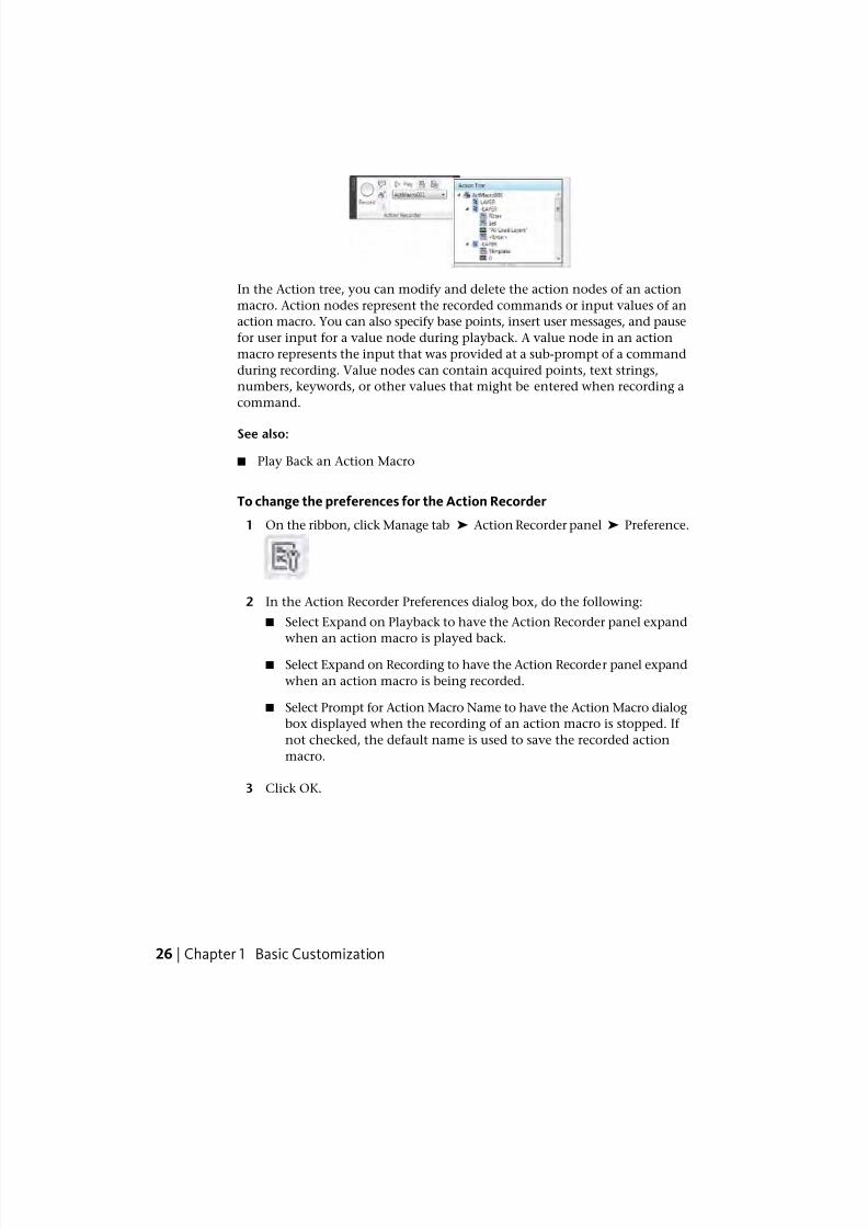
In the Action tree, you can modify and delete the action nodes of an action
macro. Action nodes represent the recorded commands or input values of an
action macro. You can also specify base points, insert user messages, and pause
for user input for a value node during playback. A value node in an action
macro represents the input that was provided at a sub-prompt of a command
during recording. Value nodes can contain acquired points, text strings,
numbers, keywords, or other values that might be entered when recording a
command.
See also:
■ Play Back an Action Macro
To change the preferences for the Action Recorder
1 On the ribbon, click Manage tab ➤ Action Recorder panel ➤ Preference.
2 In the Action Recorder Preferences dialog box, do the following:
■ Select Expand on Playback to have the Action Recorder panel expand
when an action macro is played back.
■ Select Expand on Recording to have the Action Recorder panel expand
when an action macro is being recorded.
■ Select Prompt for Action Macro Name to have the Action Macro dialog
box displayed when the recording of an action macro is stopped. If
not checked, the default name is used to save the recorded action
macro.
3 Click OK.
26 | Chapter 1 Basic Customization
7/23/2019 Acad Customization
http://slidepdf.com/reader/full/acad-customization 35/553
Quick Reference
Commands
ACTRECORD
Starts the Action Recorder.
ACTSTOP
Stops the Action Recorder and provides the option of saving the recorded
actions to an action macro file.
ACTUSERINPUT
Pauses for user input in an action macro.
ACTUSERMESSAGE
Inserts a user message into an action macro.
ACTBASEPOINT
Inserts a base point in an action macro.
OPTIONS
Customizes the program settings.
RIBBON
Opens the ribbon window.
System Variables
ACTPATHSpecifies the additional paths to use when locating available action macros
for playback.
ACTRECORDERSTATE
Specifies the current state of the Action Recorder.
ACTRECPATH
Specifies the path used to store new action macros.
ACTUI
Controls the behavior of the Action Recorder panel when recording and
playing back macros.
Overview of Action Macros | 27
7/23/2019 Acad Customization
http://slidepdf.com/reader/full/acad-customization 36/553
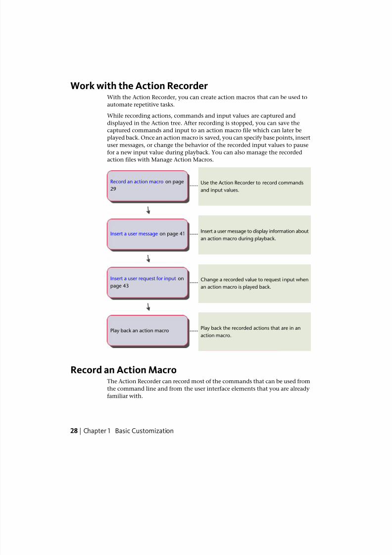
Work with the Action RecorderWith the Action Recorder, you can create action macros that can be used toautomate repetitive tasks.
While recording actions, commands and input values are captured and
displayed in the Action tree. After recording is stopped, you can save the
captured commands and input to an action macro file which can later be
played back. Once an action macro is saved, you can specify base points, insert
user messages, or change the behavior of the recorded input values to pause
for a new input value during playback. You can also manage the recorded
action files with Manage Action Macros.
Use the Action Recorder to record commands
and input values.-----
Record an action macro on page
29
Insert a user message to display information about
an action macro during playback.-----Insert a user message on page 41
Change a recorded value to request input when
an action macro is played back.-----
Insert a user request for input on
page 43
Play back the recorded actions that are in an
action macro.-----Play back an action macro
Record an Action MacroThe Action Recorder can record most of the commands that can be used from
the command line and from the user interface elements that you are alreadyfamiliar with.
28 | Chapter 1 Basic Customization
7/23/2019 Acad Customization
http://slidepdf.com/reader/full/acad-customization 37/553
Record an Action Macro with the Action Recorder
You use the Action Recorder to record commands and input values for anaction macro.
While recording an action macro, the Red Recording Circle icon is displayed
near the crosshairs to indicate that the Action Recorder is active and that
commands and input are being recorded.
While recording, commands and input that is entered at the command line
are recorded with the exception of commands that open or close drawing
files. If a dialog box is displayed while recording an action macro, only the
display of the dialog box is recorded and not the changes made to the dialog
box. It is recommended that you do not use dialog boxes when recording an
action macro. Use the command line version of the command instead. For
example, use the -HATCH command instead of the HATCH command, which
displays the Hatch and Gradient dialog box.Once you are done recording an action macro, you then have the option to
save or discard the recorded action macro. If you save the action macro, you
must specify a name and optionally, a description and the playback settings
for the action macro. The playback settings control if the view prior to the
playback of the action macro is restored when a request for user input is made
or when playback is complete.
When the Action Recorder is set to check for inconsistencies, it compares the
settings of the drawing environment when the action macro was recorded
against the current settings of the drawing environment. For example, the
Action Recorder checks the value of the INSUNITS system variable in the
current drawing against the value that was used when the action macro was
recorded. If an inconsistency is found, you are given the option to continue
playing back the action macro or to stop playback. If you continue playing
back the action macro, the action macro might produce unexpected results.
Use Action Macros while Recording
You can play back an action macro while you are recording an action macro;
you can combine multiple action macros together to create a new action
macro. To use an existing action macro while recording another action macro,
the action macro that you want to play back needs to be present in one of the
paths defined by the system variables ACTPATH or ACTRECPATH. If the action
macro is in one of the defined paths, enter the name of the action macro at
the Command prompt to play it back.
Record an Action Macro | 29
7/23/2019 Acad Customization
http://slidepdf.com/reader/full/acad-customization 38/553
Use Custom Commands and Routines with Action Macros
When recording commands and input, you can use the standard commandsthat come with AutoCAD and other custom commands that you might already
use. The custom commands that you can use is not limited to just commands
defined with AutoLISP or ObjectARX, but also includes commands defined
with .NET and macros defined with VBA.
Before playing back an action macro that contains references to custom
commands and macros, the original programs that define the commands and
macros must be loaded into AutoCAD in order for the action macro to be
played back correctly. To make sure the custom commands are available when
an action macro is played back, you can use one or more of the following.
■ Startup Suite - The Start Up Suite in the Load/Unload Applications dialog
box can be used to load files that contain custom commands.
■ ACAD.lsp or ACADDOC.lsp File - The acad.lsp or acaddoc.lsp file can be usedto automatically load files that contain custom commands.
■ Menu AutoLISP (MNL) File - A MNL file can be used to load files that
contain custom commands specific to a CUIx file.
■ Customization User Interface (CUIx) File - AutoLISP files that define custom
commands can be associated to a CUIx file by adding them to the LISP
node in the CUI Editor.
■ Script Files - A script file can be used to load AutoLISP, ObjectARX, VBA,
or .NET files. To record the running of a script file, set FILEDIA to 0 before
using the SCRIPT command.
Store Recorded Action Macros
When you stop the recording of an action macro, you have the option to save
the recorded action macro. If you save the recorded action macro, the
command name specified for the action macro is also used as the file name
of the action macro. The saved action macro is stored in the folder defined
by the ACTRECPATH system variable. You can access the folder in the Options
dialog box.
To start recording an action macro
1 On the ribbon, click Manage tab ➤ Action Recorder panel ➤ Record.
30 | Chapter 1 Basic Customization
7/23/2019 Acad Customization
http://slidepdf.com/reader/full/acad-customization 39/553
2 Use the commands and provide the input that is needed to complete the
task that you want to automate.
To stop the recording of an action macro
1 On the ribbon, click Manage tab ➤ Action Recorder panel ➤ Stop.
2 In the Action Macro dialog box, enter a name in the Action Macro
Command Name text box.
3 Optionally, do the following:
■ Enter a description for the action macro in the Description text box.
■ Under Restore Pre-playback View, select When Pausing for User Inputto restore the view prior to the playback of the action macro.
■ Under Restore Pre-playback View, select Once Playback Finishes to
restore the view prior to the playback of the action macro.
■ Select Check for Inconsistencies when Playback Begins to have the
Action Recorder validate the action macro before playback.
4 Click OK.
To cancel the recording of an action macro
1 On the ribbon, click Manage tab ➤ Action Recorder panel ➤ Stop.
2 In the Action Macro dialog box, click Cancel.
To copy an action macro to create a new action macro
1 On the ribbon, click Manage tab ➤ Action Recorder panel. Click the
down arrow next to the Action Macro list.
2 In the Action Macro list, select the action macro you want to copy.
3 Expand the Action Recorder panel.
4 In the Action tree, right-click the top node and click Copy.
Record an Action Macro | 31
7/23/2019 Acad Customization
http://slidepdf.com/reader/full/acad-customization 40/553
5 In the Action Macro dialog box, enter a name in the Action Macro Name
text box.
6 Optionally, do the following:
■ Enter a command name for the action macro in the Action Macro
Command Name text box.
■ Enter a description for the action macro in the Description text box.
■ Under Restore Pre-playback View, select When Pausing for User Input
to restore the view prior to the playback of the action macro.
■ Under Restore Pre-playback View, select Once Playback Finishes to
restore the view prior to the playback of the action macro.
■ Select Check for Inconsistencies when Playback Begins to have the
Action Recorder validate the action macro before playback.
7 Click OK.
To change the location used to save a recorded action macro
1 On the menu browzer, click Options.
2 In the Options dialog box, Files tab, in the list of nodes, click the plus
sign (+) next to Action Recorder Settings.
3 Click the plus sign (+) next to Actions Recording File Locations, and
specify a folder path.
4 Click OK.
Quick Reference
Commands
ACTRECORD
Starts the Action Recorder.
ACTSTOP
Stops the Action Recorder and provides the option of saving the recorded
actions to an action macro file.
OPTIONS
Customizes the program settings.
32 | Chapter 1 Basic Customization
7/23/2019 Acad Customization
http://slidepdf.com/reader/full/acad-customization 41/553
RIBBON
Opens the ribbon window.
System Variables
ACTPATH
Specifies the additional paths to use when locating available action macros
for playback.
ACTRECORDERSTATE
Specifies the current state of the Action Recorder.
ACTRECPATH
Specifies the path used to store new action macros.
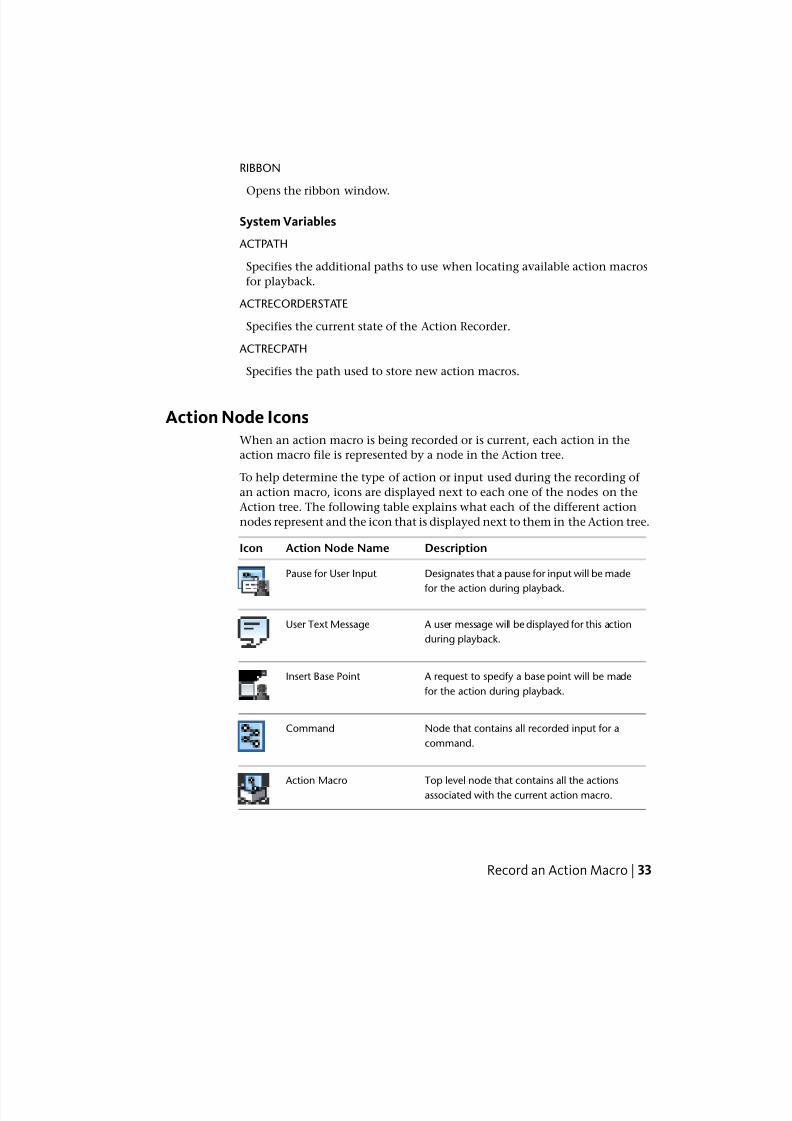
Action Node IconsWhen an action macro is being recorded or is current, each action in the
action macro file is represented by a node in the Action tree.
To help determine the type of action or input used during the recording of
an action macro, icons are displayed next to each one of the nodes on the
Action tree. The following table explains what each of the different action
nodes represent and the icon that is displayed next to them in the Action tree.
DescriptionAction Node NameIcon
Designates that a pause for input will be made
for the action during playback.
Pause for User Input
A user message will be displayed for this action
during playback.
User Text Message
A request to specify a base point will be made
for the action during playback.
Insert Base Point
Node that contains all recorded input for a
command.
Command
Top level node that contains all the actionsassociated with the current action macro.
Action Macro
Record an Action Macro | 33
7/23/2019 Acad Customization
http://slidepdf.com/reader/full/acad-customization 42/553
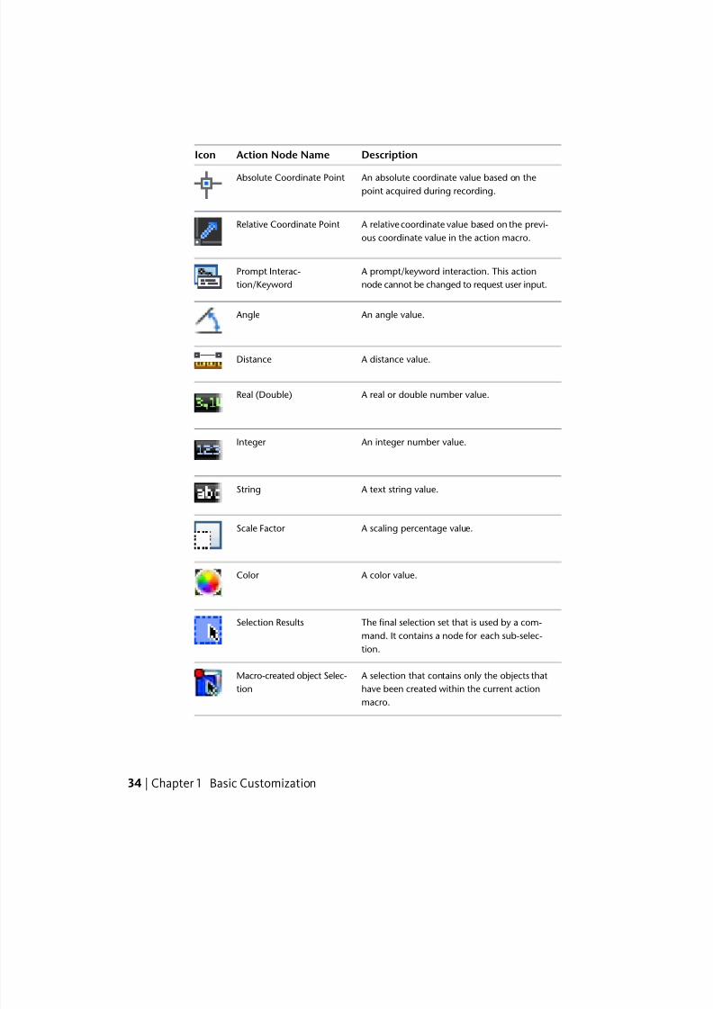
DescriptionAction Node NameIcon
An absolute coordinate value based on thepoint acquired during recording.
Absolute Coordinate Point
A relative coordinate value based on the previ-
ous coordinate value in the action macro.
Relative Coordinate Point
A prompt/keyword interaction. This action
node cannot be changed to request user input.
Prompt Interac-
tion/Keyword
An angle value. Angle
A distance value.Distance
A real or double number value.Real (Double)
An integer number value.Integer
A text string value.String
A scaling percentage value.Scale Factor
A color value.Color
The final selection set that is used by a com-
mand. It contains a node for each sub-selec-
tion.
Selection Results
A selection that contains only the objects that
have been created within the current action
macro.
Macro-created object Selec-
tion
34 | Chapter 1 Basic Customization
7/23/2019 Acad Customization
http://slidepdf.com/reader/full/acad-customization 43/553
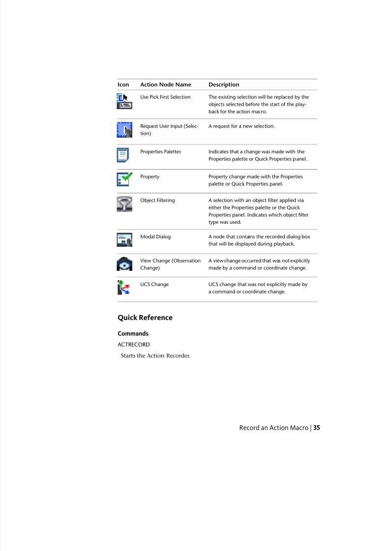
DescriptionAction Node NameIcon
The existing selection will be replaced by theobjects selected before the start of the play-
back for the action macro.
Use Pick First Selection
A request for a new selection.Request User Input (Selec-
tion)
Indicates that a change was made with the
Properties palette or Quick Properties panel.
Properties Palettes
Property change made with the Properties
palette or Quick Properties panel.
Property
A selection with an object filter applied via
either the Properties palette or the Quick
Object Filtering
Properties panel. Indicates which object filter
type was used.
A node that contains the recorded dialog box
that will be displayed during playback.
Modal Dialog
A view change occurred that was not explicitly
made by a command or coordinate change.
View Change (Observation
Change)
UCS change that was not explicitly made by
a command or coordinate change.
UCS Change
Quick Reference
Commands
ACTRECORD
Starts the Action Recorder.
Record an Action Macro | 35
7/23/2019 Acad Customization
http://slidepdf.com/reader/full/acad-customization 44/553
Work with User Interface Elements
Many of the common user interface elements can be used when recording anaction macro.
There are some elements that you cannot use. The following user interface
elements can be used when recording an action macro:
■ Toolbars and Quick Access toolbar
■ Pull-down menus and shortcut menus
■ Ribbon
■ Application menu
■ Legacy user interface elements (screen, icon, and tablet menus)
■ Application and drawing status bars
■ Properties palette and Quick Properties palette
■ Tool Palettes window
■ DesignCenter
User Interface Elements You Cannot Record
Not all actions preformed with the Properties palette and Quick Properties
palette are recorded. The following actions are not recorded:
■ Property changes made from a dialog box in the Properties palette or Quick
Properties palette.
■ Value changes made to the Vertex properties of 3D faces and polylines
with the Properties palette or Quick Properties palette.
■ Actions that do not execute a command from the status bars.
Not all actions preformed with the status bar are recorded. Only controls that
execute commands are recorded. The following buttons are recorded from
status bar:
■ Quick Properties
■ Model and layout
■
Quick View Layouts (limited to recording when layouts are switched)
36 | Chapter 1 Basic Customization
7/23/2019 Acad Customization
http://slidepdf.com/reader/full/acad-customization 45/553
■ Pan
■ Zoom
■ SteeringWheels
■ ShowMotion (limited to playing and restoring views)
■ Maximize/Minimize Viewport
■ Annotation/Viewport Scale
■ Synchronize Annotation/Viewport Scale
■ Annotation Visibility
■ Automatically Add Scales
■Lock UI
■ Clean Screen
Not all actions performed in DesignCenter are recorded. The following actions
are not recorded:
■ Inserting blocks from the DC Online tab.
■ All actions from shortcut menus except Attach as Xref and Insert as Block.
■ Dragging named objects (such as layers and linetypes).
Quick Reference
Commands
ACTRECORD
Starts the Action Recorder.
Manage and Modify Action MacrosThere are several methods for modifying and managing an action macro. You
can also edit and change the playback behavior of an action macro.
Manage and Modify Action Macros | 37
7/23/2019 Acad Customization
http://slidepdf.com/reader/full/acad-customization 46/553
Manage Action Macros
You can rename, copy, modify, and delete an action macro with the ActionMacro Manager or from the Action tree.
Modification and management of action macro file can be handled through
the Action Macro Manager and the Action tree.
Manage Files with the Action Tree
The Action tree is displayed when the Action Recorder panel is expanded. The
following options are available when you right-click the Action Macro in the
Action tree.
■ Rename. Renames the command and file name of the action macro.
■ Delete. Removes the action macro file from the Action Macro list and
places the file in the Windows Recycle Bin.
■ Copy. Creates a duplicate copy of the action macro; you specify a new
command and file name for the action macro.
■ Properties. Changes the command name and playback settings for the
action macro.
Action nodes that represent commands can be deleted and value nodes can
be edited. Action nodes in an action macro are modified through the Action
tree, which is displayed when the Action Recorder panel is expanded. The
following modify options are available when you right-click an action node
in the Action tree:
■ Delete. Removes an action node from the current action macro.
■ Edit. Replaces the current value with a new value.
Manage Action Macro Files
The Action Macro Manager dialog box performs basic file management
functionalities for your action macro (ACTM) files. You can modify, rename,
delete, and create multiple copies of an action macro file.
TIP You can select and delete a single or multiple copies of action macro files.
38 | Chapter 1 Basic Customization
7/23/2019 Acad Customization
http://slidepdf.com/reader/full/acad-customization 47/553
To rename an action macro
1 On the ribbon, click Manage tab➤
Action Recorder panel. Click thedown arrow next to the Action Macro list.
2 In the Action Macro list, select the action macro you want to rename.
3 Expand the Action Recorder panel.
4 In the Action tree, right-click the top node and click Rename.
5 In the Action Macro dialog box, in the Action Macro Command Name
text box, enter a different name.
6 Click OK.
To delete a previously recorded action macro
1 On the ribbon, click Manage tab ➤ Action Recorder panel. Click thedown arrow next to the Action Macro list.
2 In the Action Macro list, select the action macro you want to delete.
3 Expand the Action Recorder panel.
4 In the Action Tree, right-click the top node and click Delete.
5 In the Action Macro - Confirm Deletion dialog box, click Delete.
NOTE When you delete an action macro, the file that the action macro was stored
in is also moved to the Windows Recycle Bin until deleted. If you might need the
file later, move the file from the Actions folder to a different folder.
To copy an action macro
1 On the ribbon, click Manage tab ➤ Action Recorder panel. Click the
down arrow next to the Action Macro list.
2 In the Action Macro list, select the action macro you want to copy.
3 Expand the Action Recorder panel.
4 In the Action tree, right-click the top node and click Copy.
5 In the Action Macro dialog box, in the Action Macro Command Name
text box, enter a different name and optionally do the following:
■ Enter a description for the action macro in the Description text box.
Manage and Modify Action Macros | 39
7/23/2019 Acad Customization
http://slidepdf.com/reader/full/acad-customization 48/553
■ Under Restore Pre-playback View, select When Pausing For User Input
to restore the view prior to the playback of the action macro.
■ Under Restore Pre-playback View, select Once Playback Finishes to
restore the view prior to the playback of the action macro.
■ Select Check for Inconsistencies when Playback Begins to have the
Action Recorder validate the action macro before playback.
6 Click OK.
To change the properties of an action macro
1 On the ribbon, click Manage tab ➤ Action Recorder panel. Click the
down arrow next to the Action Macro list.
2 In the Action Macro list, select the action macro for which you want tochange properties.
3 Expand the Action Recorder panel.
4 In the Action tree, right-click the top node and click Properties.
5 In the Action Macro dialog box, change the properties of the action macro
by doing the following:
■ Enter a command name for the action macro in the Action Macro
Command Name text box.
■ Enter a description for the action macro in the Description text box.
■ Under Restore Pre-playback View, select When Pausinf ForUser Input
to restore the view prior to the playback of the action macro.
■ Under Restore Pre-playback View, select Once Playback Finishes to
restore the view prior to the playback of the action macro.
■ Select Check for Inconsistencies when Playback Begins to have the
Action Recorder validate the action macro before playback.
6 Click OK.
To delete an action from an action macro
1 On the ribbon, click Manage tab ➤ Action Recorder panel. Click the
down arrow next to the Action Macro list.
40 | Chapter 1 Basic Customization
7/23/2019 Acad Customization
http://slidepdf.com/reader/full/acad-customization 49/553
2 In the Action Macro list, select the action macro from which you want
to delete an action.
3 Expand the Action Recorder panel.
4 In the Action tree, right-click an action node and click Delete.
5 In the Action Macro - Confirm Deletion of Item dialog box, click Delete.
NOTE You cannot delete an action while recording an action macro.
To edit a value node in an action macro
1 On the ribbon, click Manage tab ➤ Action Recorder panel. Click the
down arrow next to the Action Macro list.
2 In the Action Macro list, select the action macro in which you want to
edit a value node.
3 Expand the Action Recorder panel.
4 In the Action tree, right-click a value node and click Edit.
5 Enter the new value and press ENTER.
Quick Reference
Commands
ACTRECORD
Starts the Action Recorder.
RIBBON
Opens the ribbon window.
ACTMANAGER
Manages action macro files.
Insert User MessagesUser messages can be inserted into an action macro to provide information
about or specific instructions for playing back an action macro.
Manage and Modify Action Macros | 41
7/23/2019 Acad Customization
http://slidepdf.com/reader/full/acad-customization 50/553
7/23/2019 Acad Customization
http://slidepdf.com/reader/full/acad-customization 51/553
Quick Reference
Commands
ACTRECORD
Starts the Action Recorder.
ACTUSERMESSAGE
Pauses for user input in an action macro.
RIBBON
Opens the ribbon window.
Pause for User InputActions in an action macro can be modified to be played back with the values
they were recorded with or to pause for input during playback.
While recording an action macro, you might choose a point or provide input
that you do not want to use each time the action macro is played back. You
can toggle the behavior of a value node in the current action macro to pause
for input during playback. A value node might contain an acquired point,
text string, number, command option, or object selection. If an action macro
pauses for input, you can provide a new input value during playback.
To toggle the pause for input of a value during the playback of an actionmacro.
1 On the ribbon, click Manage tab➤
Action Recorder panel. Click thedown arrow next to the Action Macro list.
2 In the Action Macro list, select the action macro that contains the value
node that you want to pause for input during playback.
3 Expand the Action Recorder panel.
4 In the Action tree, right-click the value node and click Pause for User
Input.
Manage and Modify Action Macros | 43

7/23/2019 Acad Customization
http://slidepdf.com/reader/full/acad-customization 52/553
Quick Reference
Commands
ACTRECORD
Starts the Action Recorder.
ACTUSERINPUT
Inserts a user message into an action macro.
RIBBON
Opens the ribbon window.
Work with CoordinatesYou can use absolute or relative coordinates for acquired points in an action
macro.
As you record an action macro, recorded coordinate values can be represented
as absolute or relative. While a coordinate value can be absolute or relative,
the stored value for all recorded coordinate values is absolute. Since all
coordinate values are stored as absolute with an action macro, you can toggle
between using the absolute or relative to previous point value for a recorded
coordinate value during playback. The first recorded coordinate value or
coordinate value after a UCS change is always defined as absolute. An absolute
coordinate value in an action macro is used as the base point for all later
relative coordinate values.
You can toggle the behavior of a coordinate value from the Action tree on theAction Recorder. You can also change all coordinate values in an action macro
to be relative or absolute from the top node in the Action tree.
To toggle a coordinate value to be absolute or relative to the previous point
1 On the ribbon, click Manage tab ➤ Action Recorder panel. Click the
down arrow next to the Action Macro list.
2 In the Action Macro list, select the action macro that contains the
coordinate value node you want to modify.
3 Expand the Action Recorder panel.
44 | Chapter 1 Basic Customization
7/23/2019 Acad Customization
http://slidepdf.com/reader/full/acad-customization 53/553
4 In the Action tree, right-click the coordinate value node and click Relative
to Previous.
■ To make a coordinate value absolute, click Relative to Previous if a
check mark is present before it. If no check mark is present, then the
coordinate value is already absolute.
■ To make a coordinate value relative to the previous point, click Relative
to Previous if a check mark is not present before it. If a check mark is
present, then the coordinate value is already relative to the previous
point.
To toggle all coordinate values to be absolute or relative to the previouspoint
1 On the ribbon, click Manage tab ➤ Action Recorder panel. Click the
down arrow next to the Action Macro list.
2 In the Action Macro list, select the action macro that contains the
coordinate value node that you want to be absolute or relative to the
previous coordinate.
3 Expand the Action Recorder panel.
4 In the Action tree, right-click the top node and click All Points Are
Relative.
■ To make all coordinate values absolute, click All Points Are Relative
if a check mark is present before it. If no check mark is present, then
the coordinate values might already be absolute; there might also be
a combination of absolute and relative coordinate values in the macro.
NOTE To be sure all coordinate values are absolute when All Points Are
Relative is not checked, select All Points Are Relative twice to avoid some
coordinate values being absolute while others are set relative to the
previous point.
■ To make all coordinate values relative to the previous point, except
for the first coordinate value, click Relative to Previous if a check mark
is not present before it. If a check mark is present, then all coordinate
values are already relative to the previous point with the exception
of the first coordinate value, which is always absolute.
Manage and Modify Action Macros | 45
7/23/2019 Acad Customization
http://slidepdf.com/reader/full/acad-customization 54/553
Quick Reference
Commands
ACTRECORD
Starts the Action Recorder.
RIBBON
Opens the ribbon window.
Insert Base PointsInserting a base point establishes an absolute coordinate which is used by the
relative coordinate points that follow the base point in the action macro.
During the playback of an action macro, by default, a request to specify a new
coordinate point is made for each base point in the action macro.
In the Action tree, base points can be inserted on an action macro or command
node. You can insert base points at any time during recording. After recording,
you can insert or delete base points from an action macro.
NOTE In the Action tree, you can right-click a base point and disable Pause for
User Input. This eliminates the default behavior of the base point from requesting
a new coordinate point during playback.
To insert a base point into an action macro
1 On the ribbon, click Manage tab ➤ Action Recorder panel. Click the
down arrow next to the Action Macro list.
2 In the Action Macro list, select the action macro that you want to modify
by inserting a base point.
3 Expand the Action Recorder panel.
4 In the Action tree, right-click a node and click Insert Base Point.
5 Click OK.
46 | Chapter 1 Basic Customization
7/23/2019 Acad Customization
http://slidepdf.com/reader/full/acad-customization 55/553
Quick Reference
Commands
ACTRECORD
Starts the Action Recorder.
ACTBASEPOINT
Inserts a base point in an action macro.
RIBBON
Opens the ribbon window.
Work with Object SelectionsSelection nodes are modified through the Action tree to control which objects
are used for the commands in an action macro.
When modifying an action macro, you can control the selection method to
use when playing back an action macro. You can use one of the following
options to alter the behavior of how objects are selected for the selection
results node in an action macro:
■ Use Pick First. Uses the objects selected prior to the start of the action
macro.
■ Pause for User Input. Prompts for a new selection set.
■ Use Macro-Created Object Selection. Selects all the objects that have been
created since the start of the action macro.
To pause for user input for a selection during playback
1 On the ribbon, click Manage tab ➤ Action Recorder panel. Click the
down arrow next to the Action Macro list.
2 In the Action Macro list, select the action macro that contains the
selection results node that you want to pause for user input during
playback.
3 Expand the Action Recorder panel.
4 In the Action tree, right-click the selection results to node and click Pause
for User Input.
Manage and Modify Action Macros | 47
7/23/2019 Acad Customization
http://slidepdf.com/reader/full/acad-customization 56/553
To toggle the use of macro-created selection during playback
1 On the ribbon, click Manage tab➤
Action Recorder panel. Click thedown arrow next to the Action Macro list.
2 In the Action Macro list, select the action macro that contains the
selection results node that you want to represent a selection of all the
objects created during the macro playback.
3 Expand the Action Recorder panel.
4 In the Action tree, right-click the selection results node and click
Macro-created Object Selection.
To use Pick First selection during playback
1 On the ribbon, click Manage tab ➤ Action Recorder panel. Click the
down arrow next to the Action Macro list.
2 In the Action Macro list, select the action macro that contains the
selection results node that you want to represent the Pick First selection
of all the objects selected before a macro is played back.
3 Expand the Action Recorder panel.
4 In the Action tree, right-click the selection results node and click Use Pick
First Set.
Quick Reference
Commands ACTRECORD
Starts the Action Recorder.
RIBBON
Opens the ribbon window.
Tips for Using the Action RecorderThe Action Recorder is designed to be intuitive and allow you to create custom
commands that can reduce the number of actions required to perform a
repetitive task. There are some things to consider when recording an action
macro.
48 | Chapter 1 Basic Customization
7/23/2019 Acad Customization
http://slidepdf.com/reader/full/acad-customization 57/553
Recording Action Macros
When recording an action macro, you should be aware of the following:
■ The current drawing settings used when recording an action macro are
not completely retained by an action macro. To make sure that specific
drawing settings are used during playback, record them as part of the action
macro using the system variable name or the SETVAR command.
■ While many commands are recorded, there are some commands that are
not recorded. The commands that are not recorded are related to drawing
file operations, working with the Action Recorder, and grip editing. The
following table lists the commands that are not recorded by the Action
Recorder.
ACTUSERINPUT ACTSTOP
-ACTUSERMESSAGE ACTUSERMESSAGE
EXPORTLAYOUTDXFIN
NEWFILEOPEN
PARTIALOPENOPEN
QNEWPRESSPULL
TABLEDITRECOVER
-VBALOAD VBAIDE
VBAMAN VBALOAD
VBAPREF VBANEW
VBARUN-VBARUN
VBAUNLOAD VBASTMT
ACTBASEPOINTXOPEN
ACTMANAGER
Tips for Using the Action Recorder | 49
7/23/2019 Acad Customization
http://slidepdf.com/reader/full/acad-customization 58/553
■ Actions recorded with the Action Recorder are limited to interactions with
the Properties palette, Quick Properties palette, the Layer Modeless dialog
box, and any user interface element that starts a command.Some of the user interface elements that start commands are: most tools
on tool palettes, some actions in DesignCenter, and some tools on the
status bars.
■ When a view change occurs, that is not explicitly made by a command or
coordinate change, (such as with the ViewCube, mouse wheel, or 3D Orbit),
a View Change (Observation Change) node is added to the Action tree.
You can delete a View Change node when recording is stopped. Upon
deletion, during playback, you might be prompted to provide input or
continue the playback because the view change did not occur. This might
affect the creation of a selection set or the use of a command.
NOTE Before deleting a View Change node, consider creating a copy of the
original macro file since you cannot undo the deletion of the node.
■ Changes to a dialog box are not recorded, but the dialog box is displayed
during playback. Instead of using a dialog box during recording, use the
command line version of the command to ensure that the action macro
behaves consistently each time it is played back.
■ Commands defined with AutoLISP and ObjectARX can be recorded with
an action macro, but the command must be loaded before the action macro
is played back. VBA macros and .NET assemblies can also be recorded as
part of an action macro, but they must be loaded in order to be played
back.
■ Action macros cannot have the same name as a command that is alreadydefined and loaded into AutoCAD.
■ The direction of an arc segment created with the Arc option of the PLINE
command is not played back correctly unless the Direction option is used
to define the arc segment.
■ While recording an action macro, you can record the current default value
displayed on the command line or use the default value that is current
when the action macro is played back. Pressing Enter without entering a
specific value during recording, displays a dialog box where you select to
use the current value during recording or the default value at playback.
■ While recording the TABLE command, the creation of the table is recorded
but any edits made to the cells of the table are not recorded.
50 | Chapter 1 Basic Customization
7/23/2019 Acad Customization
http://slidepdf.com/reader/full/acad-customization 59/553
Editing an Action Macro
When editing an action macro, the action macro files that are found in thepaths defined by the system variables ACTRECPATH and ACTPATHare loaded.
If more than one action macro file has the same name, the first action macro
file that is found is loaded into the Action Recorder. The other files with the
same names are ignored and not loaded.
To identify the path of a loaded action macro, select the action macro from
the Action Macros drop-down list and expand the Action Recorder panel.
Right-click the action macro’s node in the Action tree and click Properties. In
the Action Macro dialog box, the path to the action macro file is displayed in
the Folder Path text box.
Playing Back an Action Macro
When playing back an action macro, you should be aware of the following:
■ When playing back an action macro, the results of an action macro may
vary from those achieved when initially recording the action macro due
to differences between the drawing settings in the current drawing and
the one open when the action macro was recorded.
■ When playing back an action macro that displays a dialog box, the macro
will pause and wait until the dialog box is dismissed after changes are
made. If the dialog box is canceled, the macro will continue to play back
but the results may differ from those expected.
■ When playing back an action macro that contains commands defined with
AutoLISP, ObjectARX, or .NET assemblies, playback of the action macro
will fail if the files that define the commands are not loaded. If an action
macro references a VBA macro, the playback of the action macro will failif the project file is not loaded.
Exchanging Action Macros
When exchanging action macros with others, you should be aware of the
following:
■ Action macros recorded with one of the AutoCAD based vertical products
may not play back correctly based on the commands that were used when
the action macro was recorded.
■ Action macros may not play back correctly when recorded in one language
of AutoCAD and then played back with a different language of AutoCAD.
Tips for Using the Action Recorder | 51
7/23/2019 Acad Customization
http://slidepdf.com/reader/full/acad-customization 60/553
Quick Reference
Commands
ACTRECORD
Starts the Action Recorder.
RIBBON
Opens the ribbon window.
Examples of Action MacrosThe following examples show some of the ways that action macros can
automate repetitive tasks. The examples shows some of the different ways that
you can record actions with the Action Recorder.
Create a New Layer and Draw ObjectsIn this example, you create an action macro that makes a new layer and then
draws objects on the layer to create a two-dimensional top view of a hexagon
bolt.
In this example, you learn how to
■ Record and save an action macro
■ Record commands and input values to create and modify a new layer
■Record commands and input values to create and modify objects
■ Insert a user message
■ Insert base point
■ Pause for user input
■ Play back an action macro
Start Recording an Action Macro
You start recording actions in the Action Recorder panel. To display the Action
Recorder panel and start recording, follow these steps:
1 On the ribbon, click the Manage tab.
52 | Chapter 1 Basic Customization
7/23/2019 Acad Customization
http://slidepdf.com/reader/full/acad-customization 61/553
2 On the Action Recorder panel, click Record.
Record commands and input values to create and modify a new layer
Once the Action Recorder starts recording, you use the Layer Properties
Manager to create a new layer. Follow these steps:
1 At the Command prompt, enter -layer and press Enter.
2 At the prompt, Enter an option
[?/Make/Set/New/Rename/ON/OFF/Color/Ltype/LWeight/MATerial/Plot/Freeze/Thaw/LOck/Unlock/stAte/Description/rEconcile],
enter m and press Enter.
3 At the prompt, Enter name for new layer (becomes the current layer) <0>,
enter Bolt and press Enter.
4 At the prompt, Enter an option
[?/Make/Set/New/Rename/ON/OFF/Color/Ltype/LWeight/MATerial/Plot/Freeze/Thaw/LOck/Unlock/stAte/Description/rEconcile],
enter c and press Enter.
5 At the prompt, New color [Truecolor/COlorbook], enter 1 and press Enter.
6 At the prompt, Enter name list of layer(s) for color 1 (red) <Bolt>, press
Enter to assign the color Red to the Bolt layer.
If the Action Macro - Value Not Recorded dialog box is displayed, click
the Use the Value that is Current at Playback link. This will assign the
color specified to the to the recent layer that was created with the Make
option.
7 Press Enter again to exit the -LAYER command.
Record Commands and Input Values Used to Create and Modify Objects
Creating the Bolt layer has been recorded. Next, you create a circle and then
a six sided polygon based on the center of the circle for a hexagon bolt. Once
the circle and polygon are drawn, you use the SCALE command to control
the size of the hexagon bolt when the action macro is played back. Follow
these steps:
1 At the Command prompt, enter circle and press Enter.
2 At the prompt, Specify center point for circle or [3P/2P/Ttr (tan tan
radius)], click in the drawing window.
3 At the prompt, Specify radius of circle or [Diameter], enter 0.9 and press
ENTER.
Examples of Action Macros | 53
7/23/2019 Acad Customization
http://slidepdf.com/reader/full/acad-customization 62/553
4 At the Command prompt, enter polygon and press Enter.
5 At the prompt, Enter number of sides <4>, enter 6 and press Enter.
6 At the prompt, Specify center of polygon or [Edge], use the Center object
snap and select the edge of the circle.
7 At the prompt, Enter an option [Inscribed in circle/Circumscribed about
circle] <C>, enter c and press Enter.
8 At the prompt, Specify radius of circle, enter 1 and press Enter.
9 At the Command prompt, enter scale and press Enter.
10 At the prompt, Select objects, select both the circle and polygon and press
Enter.
11 At the prompt, Specify base point, use the Center object snap and select
the edge of the circle.
12 At the prompt, Specify scale factor or [Copy/Reference] <1.0000>, enter
1 and press Enter.
Stop Recording and Save an Action Macro
After all the actions have been recorded, you stop recording and save the
recorded actions to an action macro file. Follow these steps:
1 On the Action Recorder panel, click Stop.
2 In the Action Macro dialog box, do the following:
■ In the Action Macro Command Name box, enter CreateBolt.
■ In the Description box, enter Creates a hexagon bolt.
3 Click OK.
Insert a User Message
With a user message, you can provide instructions or general information
about the action macro to the user before any changes are made to the drawing
during playback. To insert a user message in the action macro, follow these
steps:
1 On the Action Recorder panel, click the title bar to expand the panel.
2 In the Action tree, select the CreateBolt node and right-click. Click Insert
User Message.
54 | Chapter 1 Basic Customization
7/23/2019 Acad Customization
http://slidepdf.com/reader/full/acad-customization 63/553
3 In the Insert User Message dialog box, enter Creates a hexagon bolt by
drawing a circle and polygon. During playback you are prompted for the
center point of the circle and size of the bolt. Click OK.
Insert a Base Point
With insert a base point, you are prompted to specify a base point when
playing back an action macro. In this action macro, you specify a base point
used for the center point of the circle during playback. Follow these steps:
1 On the Action Recorder panel, click the title bar to expand the panel.
2 In the Action tree, select the Circle action node and right-click. Click
Insert Base Point.
Pause for User InputWith a pause for user input, you are prompted to enter a value when playing
back an action macro. In this action macro, you change the scale factor for
the SCALE command to pause for user input during play back. Follow these
steps:
1 On the Action Recorder panel, click the title bar to expand the panel.
2 Select the Scale Factor value node under the Scale action node and
right-click. Click Pause for User Input.
Play Back the Action Macro
When you play back the action macro, you are prompted to specify a base
point of a circle and the scale factor for the SCALE command. To see the resultsof the action macro, follow these steps:
1 On the Action Recorder panel, on the Action Macro list, select CreateBolt.
2 Click Play.
3 In the User Message dialog box, click Close.
4 When prompted to specify a base point, click a coordinate point in the
drawing window.
5 The circle and polygon are drawn.
6 When prompted for a scale factor, enter a numeric value (such as 1 or
0.25) at the Command prompt and press Enter.
The circle and polygon are scaled based on the scale factor entered.
Examples of Action Macros | 55
7/23/2019 Acad Customization
http://slidepdf.com/reader/full/acad-customization 64/553
7 In the Action Macro - Playback Complete dialog box, click OK.
Quick Reference
Commands
ACTRECORD
Starts the Action Recorder.
ACTSTOP
Stops the Action Recorder and provides the option of saving the recorded
actions to an action macro file.
ACTUSERINPUT
Pauses for user input in an action macro.
ACTUSERMESSAGE
Inserts a user message into an action macro.
ACTBASEPOINT
Inserts a base point in an action macro.
CIRCLE
Creates a circle.
LAYER
Manages layers and layer properties.
POLYGON
Creates an equilateral closed polyline.
RIBBON
Opens the ribbon window.
SCALE
Enlarges or reduces selected objects, keeping the proportions of the object
the same after scaling.
56 | Chapter 1 Basic Customization
7/23/2019 Acad Customization
http://slidepdf.com/reader/full/acad-customization 65/553
Insert a Block and Change a Dynamic Property Value
This example shows how to insert a dynamic block from a tool palette andchange its dynamic properties using the Properties palette.
In this example, you learn how to
■ Record and save an action macro
■ Record actions from the Tool Palettes window
■ Modify an object using the Properties palette
■ Remove action nodes from an action macro
■ Insert Base Point
■ Play back an action macro
Start Recording an Action Macro
You start recording actions on the Action Recorder panel. To display the Action
Recorder panel and to start recording, follow these steps:
1 On the ribbon, click the Manage tab.
2 On the Action Recorder panel, click Record.
Record Actions from the Tool Palettes Window
You can use tools from a tool palette and then play back the action that is
performed by a tool. From the Tool Palettes window, you will place the I Beam
- Imperial dynamic block from the Structural tool palette. Follow these steps:
1 At the Command prompt, enter toolpalettes to display the Tool Palettes
window.
2 At the Command prompt, enter properties to display the Properties
palette.
3 In the Tool Palettes window, under the All Palettes group, click the
Structural tab.
4 On the Structural tab, click the I Beam - Imperial tool.
5 On the Properties palette, under the Custom category, click the Beam
Sizes field.
6 On the Beam Sizes drop-down list, select IPE A 140.
Examples of Action Macros | 57
7/23/2019 Acad Customization
http://slidepdf.com/reader/full/acad-customization 66/553
7 In the drawing window, specify the insertion point for the block.
Stop Recording and Save an Action Macro
After all the actions have been recorded, you stop recording and save the
recorded actions to an action macro file. Follow these steps:
1 On the Action Recorder panel, click Stop.
2 In the Action Macro dialog box, do the following
■ In the Action Macro Command Name box, enter InsertIPEA140.
■ In the Description box, enter Inserts an IPE A 140 beam.
3 Click OK.
Remove Action Nodes
When you record an action macro, at times additional actions are recorded
that you do not need. For example, while recording the action macro you
displayed the Tool Palettes window and the Properties palette. Those action
nodes are not needed in order to play back the action macro. To remove action
nodes from the action macro, follow these steps:
1 On the Action Recorder panel, click the title bar to expand the panel.
2 In the Action tree, select the TOOLPALETTES action node under the
Action Macro node and right-click. Click Delete.
3 Select the Properties action node and right-click. Click Delete.
Play Back the Action Macro
When you play back the action macro, you are prompted to specify the
insertion point of the block. To see the results of the action macro, follow
these steps:
1 On the Action Recorder panel, on the Action Macro list, select
InsertIPEA140.
2 Click Play.
3 When prompted to specify a base point, click a base point in the drawing
window to insert the block.
As the block is inserted, the beam size selected on the Properties palette
is reflected on-screen.
58 | Chapter 1 Basic Customization
7/23/2019 Acad Customization
http://slidepdf.com/reader/full/acad-customization 67/553
4 In the Action Macro - Playback Complete dialog box, click OK.
Quick Reference
Commands
ACTRECORD
Starts the Action Recorder.
ACTSTOP
Stops the Action Recorder and provides the option of saving the recorded
actions to an action macro file.
PROPERTIES
Controls properties of existing objects.
RIBBON
Opens the ribbon window.
TOOLPALETTES
Opens the Tool Palettes window.
Modify Circles with the Properties PaletteThis example shows how to apply an object filter to select objects and then
change the color property of the selected objects.
In this example, you learn how to
■ Record and save an action macro
■ Modify an object using the Properties palette
■ Select objects and use an object selection filter
■ Use Pick First selection
■ Play back an action macro
Start Recording an Action Macro
You start recording actions on the Action Recorder panel. To display the Action
Recorder panel and to start recording, follow these steps:
Examples of Action Macros | 59
7/23/2019 Acad Customization
http://slidepdf.com/reader/full/acad-customization 68/553
1 On the ribbon, click the Manage tab.
2 On the Action recorder panel, click Record.
Modify Objects Using the Properties Palette and Object Selection Filter
When working with the Properties palette, you can control which objects you
modify by applying an object selection filter to the selected objects. Follow
these steps:
1 Select the objects in the drawing that you want to modify and right-click.
Click Properties.
2 On the Properties palette, in the Objects drop-down list, select Circles.
3 Under the General category, select the Color field.
4 In the Color drop-down list, select Blue.
Stop Recording and Save an Action Macro
After all the actions have been recorded, you stop recording and save the
recorded actions to an action macro file. Follow these steps:
1 On the Action Recorder panel, click Stop.
2 In the Action Macro dialog box, do the following
■ In the Action Macro Command Name box, enter BlueCircles.
■ In the Description box, enter Changes the color of all selected circles
to blue.
3 Click OK.
Change the Selection Set to Use the Pick First Selection Set
With a request for user input, you are prompted for a value to be entered
instead of using a recorded value when playing back an action macro. In this
action macro, you change the selection set created to use the Pick First
selection. Follow these steps:
1 On the Action Recorder panel, click the title bar to expand the panel.
2 In the Action tree, under the Action Macro node, select the Pickfirst value
node and right-click. Click Use Pick First Set.
60 | Chapter 1 Basic Customization
7/23/2019 Acad Customization
http://slidepdf.com/reader/full/acad-customization 69/553
Play Back the Action Macro
When you play back the action macro, you are prompted to select objects if no objects are selected. To see the results of the action macro, follow these
steps:
1 Draw some circles and other objects in the drawing. Change the colors
of the objects to colors other than blue.
2 On the Action Recorder panel, on the Action Macro list, select BlueCircles.
3 Click Play.
4 In the Action Macro - No Objects Selected dialog box, click Select Objects
and Continue.
5 When prompted to select objects, select the circles and the other objects
in the drawing. Press ENTER to complete object selection.
The circles in the selection set are changed to the color blue.
6 If the Action Macro - Playback Complete dialog box is displayed, click
OK.
Undo the changes made by the action macro by clicking Undo from the Quick
Access toolbar. Now select some objects in the drawing and playback the
BlueCircles action macro. This time the action macro uses the Pick First
selection and you are not prompted to select the objects in the drawing when
the action macro is played back.
Quick Reference
Commands
ACTRECORD
Starts the Action Recorder.
ACTSTOP
Stops the Action Recorder and provides the option of saving the recorded
actions to an action macro file.
PROPERTIES
Controls properties of existing objects.
RIBBON
Opens the ribbon window.
Examples of Action Macros | 61

7/23/2019 Acad Customization
http://slidepdf.com/reader/full/acad-customization 70/553
System Variables
PICKFIRSTControls whether you select objects before (noun-verb selection) or after you
issue a command.
62 | Chapter 1 Basic Customization
7/23/2019 Acad Customization
http://slidepdf.com/reader/full/acad-customization 71/553
Custom Linetypes
AutoCAD® provides a library of standard linetypes in the acad.lin and acadiso.lin files. You canuse the linetypes as they are, modify them, or create your own custom linetypes.
Overview of Linetype DefinitionsLinetypes are defined in one or more linetype definition files that have a .linfile extension.
The linetype name and definition determine the particular dash-dot sequence,
the relative lengths of dashes and blank spaces, and the characteristics of any
included text or shapes. You can use any of the standard linetypes that AutoCAD
provides, or you can create your own linetypes.
examples of linetypes
A LIN file can contain definitions of many simple and complex linetypes. You
can add new linetypes to an existing LIN file, or you can create your own LIN
file. To create or modify linetype definitions, edit the LIN file using a text editor
or word processor or use LINETYPE at the command prompt.
When you create a linetype, you must load the linetype before you can use it.
The LIN files included in AutoCAD are acad.lin and acadiso.lin. You can display
or print these text files to better understand how to construct linetypes.
2
63
7/23/2019 Acad Customization
http://slidepdf.com/reader/full/acad-customization 72/553
Quick Reference
Commands
LINETYPE
Loads, sets, and modifies linetypes.
System Variables
MEASUREINIT
Controls whether a drawing you start from scratch uses imperial or metric
default settings.
Simple Custom LinetypesEach linetype is defined on two lines in a linetype definition file. The first
line contains the linetype name and an optional description. The second line
is the code that defines the actual linetype pattern.
The second line must begin with the letter A (alignment), followed by a list
of pattern descriptors that define pen-up lengths (spaces), pen-down lengths
(dashes), and dots. You can include comments in an LIN file by beginning
the line with a semicolon (;).
Linetype Definition Format
The format of the linetype definition is
*linetype_name,description
A,descriptor1,descriptor2, ...
For example, a linetype called DASHDOT is defined as
*DASHDOT,Dash dot __ . __ . __ . __ . __ . __ . __ . __
A,.5,-.25,0,-.25
This indicates a repeating pattern starting with a dash 0.5 drawing units long,
a space 0.25 drawing units long, a dot, and another space 0.25 drawing units
long. This pattern continues for the length of the line, ending with a dash 0.5
drawing units long. The linetype would be displayed as shown below.
__ . __ . __ . __ . __ . __ . __ . __
LIN files must be saved in ASCII format and use an .lin file extension. Additional
information about each field in a linetype definition follows.
64 | Chapter 2 Custom Linetypes
7/23/2019 Acad Customization
http://slidepdf.com/reader/full/acad-customization 73/553
Linetype Name
The linetype name field begins with an asterisk (*) and should provide aunique, descriptive name for the linetype.
Description
The description of the linetype should help you visualize the linetype when
you edit the LIN file. The description is also displayed in the Linetype Manager
and in the Load or Reload Linetypes dialog box.
The description is optional and can include
■ A simple representation of the linetype pattern using ASCII text
■ An expanded description of the linetype
■ A comment such as "Use this linetype for hidden lines"
If you omit the description, do not insert a comma after the linetype name.
A description cannot exceed 47 characters.
Alignment Field (A)
The alignment field specifies the action for pattern alignment at the ends of
individual lines, circles, and arcs. Currently, AutoCAD supports only A-type
alignment, which guarantees that the endpoints of lines and arcs start and
stop with a dash.
For example, suppose you create a linetype called CENTRAL that displays the
repeating dash-dot sequence commonly used as a centerline. AutoCAD adjusts
the dash-dot sequence on an individual line so that dashes and line endpoints
coincide. The pattern fits the line so that at least half of the first dash begins
and ends the line. If necessary, the first and last dashes are lengthened. If a
line is too short to hold even one dash-dot sequence, AutoCAD draws a
continuous line between the endpoints. For arcs also, the pattern is adjusted
so that dashes are drawn at the endpoints. Circles do not have endpoints, but
AutoCAD adjusts the dash-dot sequence to provide a reasonable display.
You must specify A-type alignment by entering a in the alignment field.
Simple Custom Linetypes | 65
7/23/2019 Acad Customization
http://slidepdf.com/reader/full/acad-customization 74/553
Pattern Descriptors
Each pattern descriptor field specifies the length of segments making up thelinetype, separated by commas (no spaces are allowed):
■ A positive decimal number denotes a pen-down (dash) segment of that
length.
■ A negative decimal number denotes a pen-up (space) segment of that
length.
■ A dash length of 0 draws a dot.
You can enter up to 12 dash-length specifications per linetype, provided they
fit on one 80-character line in the LIN file. You need to include only one
complete repetition of the linetype pattern defined by pattern descriptors.
When the linetype is drawn, AutoCAD uses the first pattern descriptor for the
starting and ending dashes. Between the starting and ending dashes, the
pattern dash specifications are drawn sequentially, beginning with the second
dash specification and restarting the pattern with the first dash specification
when required.
A-type alignment requires that the first dash length be 0 or greater (a pen-down
segment). The second dash length should be less than 0 if you need a pen-up
segment and more than 0 if you are creating a continuous linetype. You must
have at least two dash specifications for A-type alignment.
To create a simple linetype from the Command prompt
1 At the command prompt, enter -linetype.
2 Enter c (Create).
3 Enter a name for the linetype and press ENTER.
The linetype name can include up to 255 characters. Linetype names can
contain letters, digits, and the special characters dollar sign ($), hyphen
(-), and underscore (_). Linetype names cannot include blank spaces.
4 In the Create or Append Linetype File dialog box, select an LIN linetype
library file from the File Name box and choose Save.
If you select an existing file, the new linetype name is added to the
linetype names in the file.
5 Enter text that describes the new linetype (optional).
66 | Chapter 2 Custom Linetypes
7/23/2019 Acad Customization
http://slidepdf.com/reader/full/acad-customization 75/553
6 At the Enter Pattern prompt, specify the pattern of the line. Follow these
guidelines:
■ All linetypes must begin with a dash.
■ Enter zeros for dots.
■ Enter negative real numbers for spaces. The value defines the length
of the space in drawing units.
■ Enter positive real numbers for dashes. The value defines the length
of the dash in drawing units.
■ Separate each dot, dash, or space value from the next with a comma.
■ Use a space between a dot and a dash.
7 Press ENTER to end the command.
NOTE When you create a linetype, it is not loaded into your drawing automatically.
Use the Load option of LINETYPE.
To add a simple linetype to a LIN file
1 Open the acad.lin or acadiso.lin file in a text editor that saves in ASCII
format (for example, Notepad).
2 Create a header line that includes an asterisk and a linetype pattern name.
The name of the linetype pattern is limited to 31 characters.
3 (Optional) To include a description in the header line, follow the linetype
pattern name with a comma and description text.
4 Create a descriptor line that includes:
■ All linetypes must begin with a dash.
■ Enter zeros for dots.
■ Enter negative real numbers for spaces. The value defines the length
of the space in drawing units.
■ Enter positive real numbers for dashes. The value defines the length
of the dash in drawing units.
■ Separate each dot, dash, or space value from the next with a comma.
■ Use a space between a dot and a dash.
Simple Custom Linetypes | 67
7/23/2019 Acad Customization
http://slidepdf.com/reader/full/acad-customization 76/553
Quick Reference
Commands
LINETYPE
Loads, sets, and modifies linetypes.
System Variables
MEASUREINIT
Controls whether a drawing you start from scratch uses imperial or metric
default settings.
Text in Custom LinetypesCharacters from text fonts can be included in linetypes.
Characters from text fonts can be included in linetypes. Linetypes with
embedded characters can denote utilities, boundaries, contours, and so on.
As with simple linetypes, lines are dynamically drawn as you specify the
vertices. Characters embedded in lines are always displayed completely; they
are never trimmed.
Embedded text characters are associated with a text style in the drawing. Any
text styles associated with a linetype must exist in the drawing before you
load the linetype.
The format for linetypes that include embedded characters is similar to that
for simple linetypes in that it is a list of pattern descriptors separated by
commas.
Character Descriptor Format
The format for adding text characters in a linetype description is as follows:
["text",textstylename,scale,rotation,xoffset,yoffset]
This format is added as a descriptor to a simple linetype. For example, a
linetype called HOT_WATER_SUPPLY is defined as
*HOT_WATER_SUPPLY,---- HW ---- HW ---- HW ---- HW ---- HW ----
A,.5,-.2,["HW",STANDARD,S=.1,U=0.0,X=-0.1,Y=-.05],-.2
This indicates a repeating pattern starting with a dash 0.5 drawing units long,
a space 0.2 drawing units long, the characters HW with some scale andplacement parameters, and another space 0.2 drawing units long. The text
68 | Chapter 2 Custom Linetypes
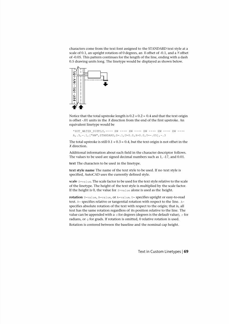
7/23/2019 Acad Customization
http://slidepdf.com/reader/full/acad-customization 77/553
characters come from the text font assigned to the STANDARD text style at a
scale of 0.1, an upright rotation of 0 degrees, an X offset of -0.1, and a Y offset
of -0.05. This pattern continues for the length of the line, ending with a dash0.5 drawing units long. The linetype would be displayed as shown below.
Notice that the total upstroke length is 0.2 + 0.2 = 0.4 and that the text origin
is offset -.01 units in the X direction from the end of the first upstroke. An
equivalent linetype would be
*HOT_WATER_SUPPLY,---- HW ---- HW ---- HW ---- HW ---- HW ----
A,.5,-.1,["HW",STANDARD,S=.1,U=0.0,X=0.0,Y=-.05],-.3
The total upstroke is still 0.1 + 0.3 = 0.4, but the text origin is not offset in the
X direction.
Additional information about each field in the character descriptor follows.
The values to be used are signed decimal numbers such as 1, -17, and 0.01.
text The characters to be used in the linetype.
text style name The name of the text style to be used. If no text style isspecified, AutoCAD uses the currently defined style.
scale S=value. The scale factor to be used for the text style relative to the scale
of the linetype. The height of the text style is multiplied by the scale factor.
If the height is 0, the value for S=value alone is used as the height.
rotation U=value, R=value, or A=value. U= specifies upright or easy-to-read
text. R= specifies relative or tangential rotation with respect to the line. A=
specifies absolute rotation of the text with respect to the origin; that is, all
text has the same rotation regardless of its position relative to the line. The
value can be appended with a d for degrees (degrees is the default value), r for
radians, or g for grads. If rotation is omitted, 0 relative rotation is used.
Rotation is centered between the baseline and the nominal cap height.
Text in Custom Linetypes | 69
7/23/2019 Acad Customization
http://slidepdf.com/reader/full/acad-customization 78/553
NOTE Drawings containing legacy linetypes that do not use the U (upright)
rotation flag can be updated to the latest linetype definition by reloading the
linetype from the LIN files. Custom linetypes can be updated by changing the R
(rotation) flag to the U (upright) flag prior to reloading a linetype definition. For
information on loading a linetype, see Load Linetypes.
xoffset X=value. The shift of the text on the X axis of the linetype, which is
along the line. If xoffset is omitted or is 0, the text is elaborated with no
offset. Use this field to control the distance between the text and the previous
pen-up or pen-down stroke. This value is not scaled by the scale factor defined
by S=value, but it is scaled to the linetype.
yoffset Y=value. The shift of the text in the Y axis of the linetype, which is at
a 90-degree angle to the line. If yoffset is omitted or is 0, the text is elaborated
with no offset. Use this field to control the vertical alignment of the text with
respect to the line. This value is not scaled by the scale factor defined byS=value, but it is scaled to the linetype.
To include text characters in linetypes
1 Create a simple linetype, as described in To add a simple linetype to a
LIN file on page 67.
2 Add the text character descriptor within the linetype pattern, using the
following format:
["text",textstylename,scale,rotation,xoffset,yoffset]
Quick Reference
Commands
LINETYPE
Loads, sets, and modifies linetypes.
System Variables
MEASUREINIT
Controls whether a drawing you start from scratch uses imperial or metric
default settings.
70 | Chapter 2 Custom Linetypes
7/23/2019 Acad Customization
http://slidepdf.com/reader/full/acad-customization 79/553
Shapes in Custom LinetypesA complex linetype can contain embedded shapes that are saved in shapefiles. Complex linetypes can denote utilities, boundaries, contours, and so on.
As with simple linetypes, complex lines are dynamically drawn as the user
specifies vertices. Shapes and text objects embedded in lines are always
displayed completely; they are never trimmed.
The syntax for complex linetypes is similar to that of simple linetypes in that
it is a comma-delimited list of pattern descriptors. Complex linetypes can
include shape and text objects as pattern descriptors, as well as dash-dot
descriptors.
The syntax for shape object descriptors in a linetype description is as follows:
[shapename,shxfilename] o r [shapename,shxfilename,transform]
where transform is optional and can be any series of the following (each
preceded by a comma):
R=## Relative rotation
A=## Absolute rotation
S=## Scale
X=## X offset
Y=## Y offset
In this syntax, ## is a signed decimal number (1, -17, 0.01, and so on), the
rotation is in degrees, and the remaining options are in linetype-scaled drawing
units. The preceding transform letters, if they are used, must be followed by
an equal sign and a number.
The following linetype definition defines a linetype named CON1LINE that
is composed of a repeating pattern of a line segment, a space, and the
embedded shape CON1 from the ep.shx file. (Note that the ep.shx file must be
in the support path for the following example to work properly.)
*CON1LINE, --- [CON1] --- [CON1] --- [CON1]
A,1.0,-0.25,[CON1,ep.shx],-1.0
Except for the code enclosed in square brackets, everything is consistent with
the definition of a simple linetype.
As previously described, a total of six fields can be used to define a shape as
part of a linetype. The first two are mandatory and position-dependent; the
Shapes in Custom Linetypes | 71
7/23/2019 Acad Customization
http://slidepdf.com/reader/full/acad-customization 80/553
next four are optional and can be ordered arbitrarily. The following two
examples demonstrate various entries in the shape definition field.
[CAP,ep.shx,S=2,R=10,X=0.5]
The code above draws the CAP shape defined in the ep.shx shape file with a
scale of two times the unit scale of the linetype, a tangential rotation of 10
degrees in a counterclockwise direction, and an X offset of 0.5 drawing units
before shape elaboration takes place.
[DIP8,pd.shx,X=0.5,Y=1,R=0,S=1]
The code above draws the DIP8 shape defined in the pd.shx shape file with an
X offset of 0.5 drawing units before shape drawing takes place, and a Y offset
of one drawing unit above the linetype, with 0 rotation and a scale equal to
the unit scale of the linetype.
The following syntax defines a shape as part of a complex linetype.
[shapename,shapefilename,scale,rotate,xoffset,yoffset]
The definitions of the fields in the syntax follow.
shapename The name of the shape to be drawn. This field must be included.
If it is omitted, linetype definition fails. If shapename does not exist in the
specified shape file, continue drawing the linetype but without the embedded
shape.
shapefilename The name of a compiled shape definition file (SHX). If it is
omitted, linetype definition fails. If shapefilename is unqualified (that is, no
path is specified), search the library path for the file. If shapefilename is fully
qualified and not found at that location, remove the prefix and search the
library path for the file. If it is not found, continue drawing the linetype but
without the embedded shape.
scale S=value. The scale of the shape is used as a scale factor by which the
shape's internally defined scale is multiplied. If the shape's internally defined
scale is 0, the S=value alone is used as the scale.
rotate R=value or A=value. R= signifies relative or tangential rotation with
respect to the line's elaboration. A= signifies absolute rotation of the shape
with respect to the origin; all shapes have the same rotation regardless of their
relative position to the line. The value can be appended with a d for degrees
(if omitted, degree is the default), r for radians, or g for grads. If rotation is
omitted, 0 relative rotation is used.
xoffset X=value. The shift of the shape in the X axis of the linetype computed
from the end of the linetype definition vertex. If xoffset is omitted or is 0,
72 | Chapter 2 Custom Linetypes
7/23/2019 Acad Customization
http://slidepdf.com/reader/full/acad-customization 81/553
the shape is elaborated with no offset. Include this field if you want a
continuous line with shapes. This value is not scaled by the scale factor defined
by S=.
yoffset Y=value. The shift of the shape in the Y axis of the linetype computed
from the end of the linetype definition vertex. If yoffset is omitted or 0, the
shape is elaborated with no offset. This value is not scaled by the scale factor
defined by S=.
See also:
■ Shapes and Shape Fonts on page 453
Quick Reference
Commands
LINETYPE
Loads, sets, and modifies linetypes.
SHAPE
Inserts a shape from a shape file that has been loaded using LOAD.
System Variables
MEASUREINIT
Controls whether a drawing you start from scratch uses imperial or metric
default settings.
Shapes in Custom Linetypes | 73

7/23/2019 Acad Customization
http://slidepdf.com/reader/full/acad-customization 82/553
74
7/23/2019 Acad Customization
http://slidepdf.com/reader/full/acad-customization 83/553
Custom Hatch Patterns
AutoCAD® provides a library of standard hatch patterns in the acad.pat and acadiso.pat files.You can use the hatch patterns as they are, modify them, or create your own custom hatchpatterns.
Overview of Hatch Pattern DefinitionsIn addition to using the predefined hatch patterns that are supplied, you can
design and create your own custom hatch patterns.
In addition to using the predefined hatch patterns that are supplied, you can
design and create your own custom hatch patterns. Developing a hatch pattern
definition requires knowledge, practice, and patience. Because customizing
hatches requires familiarity with hatch patterns, it is not recommended for new
users.
The hatch patterns supplied by AutoCAD are stored in the acad.pat and
acadiso.pat text files. You can add hatch pattern definitions to this file or create
your own files.
Regardless of where the definition is stored, a custom hatch pattern has the
same format. It has a header line with a name, which begins with an asterisk
and is no more than 31 characters long, and an optional description:
* pattern-name, description
It also has one or more line descriptors of the following form:
angle, x-origin,y-origin, delta-x ,delta-y ,dash-1,dash-2, …
The default hatch pattern ANSI31 shown in the Boundary Hatch and Fill dialog
box looks like this:
3
75
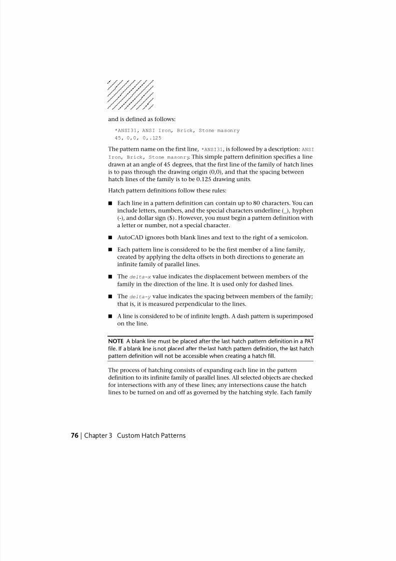
7/23/2019 Acad Customization
http://slidepdf.com/reader/full/acad-customization 84/553
and is defined as follows:
*ANSI31, ANSI Iron, Brick, Stone masonry
45, 0,0, 0,.125
The pattern name on the first line, *ANSI31, is followed by a description: ANSI
Iron, Brick, Stone masonry. This simple pattern definition specifies a line
drawn at an angle of 45 degrees, that the first line of the family of hatch lines
is to pass through the drawing origin (0,0), and that the spacing between
hatch lines of the family is to be 0.125 drawing units.
Hatch pattern definitions follow these rules:
■ Each line in a pattern definition can contain up to 80 characters. You can
include letters, numbers, and the special characters underline (_), hyphen
(-), and dollar sign ($). However, you must begin a pattern definition with
a letter or number, not a special character.
■ AutoCAD ignores both blank lines and text to the right of a semicolon.
■ Each pattern line is considered to be the first member of a line family,
created by applying the delta offsets in both directions to generate an
infinite family of parallel lines.
■ The delta-x value indicates the displacement between members of the
family in the direction of the line. It is used only for dashed lines.
■ The delta-y value indicates the spacing between members of the family;that is, it is measured perpendicular to the lines.
■ A line is considered to be of infinite length. A dash pattern is superimposed
on the line.
NOTE A blank line must be placed after the last hatch pattern definition in a PAT
file. If a blank line is not placed after the last hatch pattern definition, the last hatch
pattern definition will not be accessible when creating a hatch fill.
The process of hatching consists of expanding each line in the pattern
definition to its infinite family of parallel lines. All selected objects are checked
for intersections with any of these lines; any intersections cause the hatch
lines to be turned on and off as governed by the hatching style. Each family
76 | Chapter 3 Custom Hatch Patterns
7/23/2019 Acad Customization
http://slidepdf.com/reader/full/acad-customization 85/553
of hatch lines is generated parallel to an initial line with an absolute origin
to guarantee proper alignment.
If you create a very dense hatch, AutoCAD may reject the hatch and display
a message indicating that the hatch scale is too small or its dash length too
short. You can change the maximum number of hatch lines by setting the
MaxHatch system registry variable using (setenv “MaxHatch” “n”) where n is
a number between 100 and 10000000 (ten million).
NOTE When changing the value of MaxHatch, you must enter MaxHatch with
the capitalization as shown.
To create a simple hatch pattern
1 Open the acad.pat or acadiso.pat file in a text editor that saves in ASCII
format (for example, Microsoft®
Windows®
Notepad).
2 Create a header line that includes an asterisk and a pattern name. The
name of the hatch pattern is limited to 31 characters.
3 (Optional) To include a description in the header line, follow the pattern
name with a comma and description text.
4 Create a descriptor line that includes
■ An angle at which the line is drawn
■ An X,Y origin point
■ A delta-x of 0
■ A delta-y of any value
Quick Reference
Commands
ADCENTER
Manages and inserts content such as blocks, xrefs, and hatch patterns.
FILL
Controls the filling of objects such as hatches, 2D solids, and wide polylines.
Overview of Hatch Pattern Definitions | 77
7/23/2019 Acad Customization
http://slidepdf.com/reader/full/acad-customization 86/553
HATCH
Fills an enclosed area or selected objects with a hatch pattern, solid fill, orgradient fill.
HATCHEDIT
Modifies an existing hatch or fill.
SOLID
Creates solid-filled triangles and quadrilaterals.
System Variables
FILLMODE
Specifies whether hatches and fills, 2D solids, and wide polylines are filled
in.
HPANG
Sets the angle for new hatch patterns.
HPBOUND
Controls the object type created by HATCH and BOUNDARY.
HPDOUBLE
Specifies hatch pattern doubling for user-defined patterns.
HPNAME
Sets the default hatch pattern name.
HPSCALE
Sets the hatch pattern scale factor.
HPSPACE
Sets the hatch pattern line spacing for user-defined patterns.
Hatch Patterns with Dashed LinesTo define dashed-line patterns, you append dash-length items to the end of
the line definition item.
To define dashed-line patterns, you append dash-length items to the end of
the line definition item. Each dash-length item specifies the length of a
segment making up the line. If the length is positive, a pen-down segment is
78 | Chapter 3 Custom Hatch Patterns
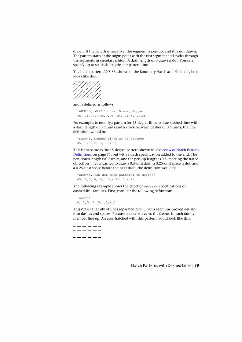
7/23/2019 Acad Customization
http://slidepdf.com/reader/full/acad-customization 87/553
drawn. If the length is negative, the segment is pen-up, and it is not drawn.
The pattern starts at the origin point with the first segment and cycles through
the segments in circular fashion. A dash length of 0 draws a dot. You canspecify up to six dash lengths per pattern line.
The hatch pattern ANSI33, shown in the Boundary Hatch and Fill dialog box,
looks like this:
and is defined as follows:
*ANSI33, ANSI Bronze, Brass, Copper
45, .176776695,0, 0,.25, .125,-.0625
For example, to modify a pattern for 45-degree lines to draw dashed lines with
a dash length of 0.5 units and a space between dashes of 0.5 units, the line
definition would be
*DASH45, Dashed lines at 45 degrees
45, 0,0, 0,.5, .5,-.5
This is the same as the 45-degree pattern shown in Overview of Hatch Pattern
Definitions on page 75, but with a dash specification added to the end. The
pen-down length is 0.5 units, and the pen-up length is 0.5, meeting the stated
objectives. If you wanted to draw a 0.5-unit dash, a 0.25-unit space, a dot, and
a 0.25-unit space before the next dash, the definition would be
*DDOT45,Dash-dot-dash pattern: 45 degrees
45, 0,0, 0,.5, .5,-.25, 0,-.25
The following example shows the effect of delta-x specifications on
dashed-line families. First, consider the following definition:
*GOSTAK
0, 0,0, 0,.5, .5,-.5
This draws a family of lines separated by 0.5, with each line broken equally
into dashes and spaces. Because delta-x is zero, the dashes in each family
member line up. An area hatched with this pattern would look like this:
Hatch Patterns with Dashed Lines | 79
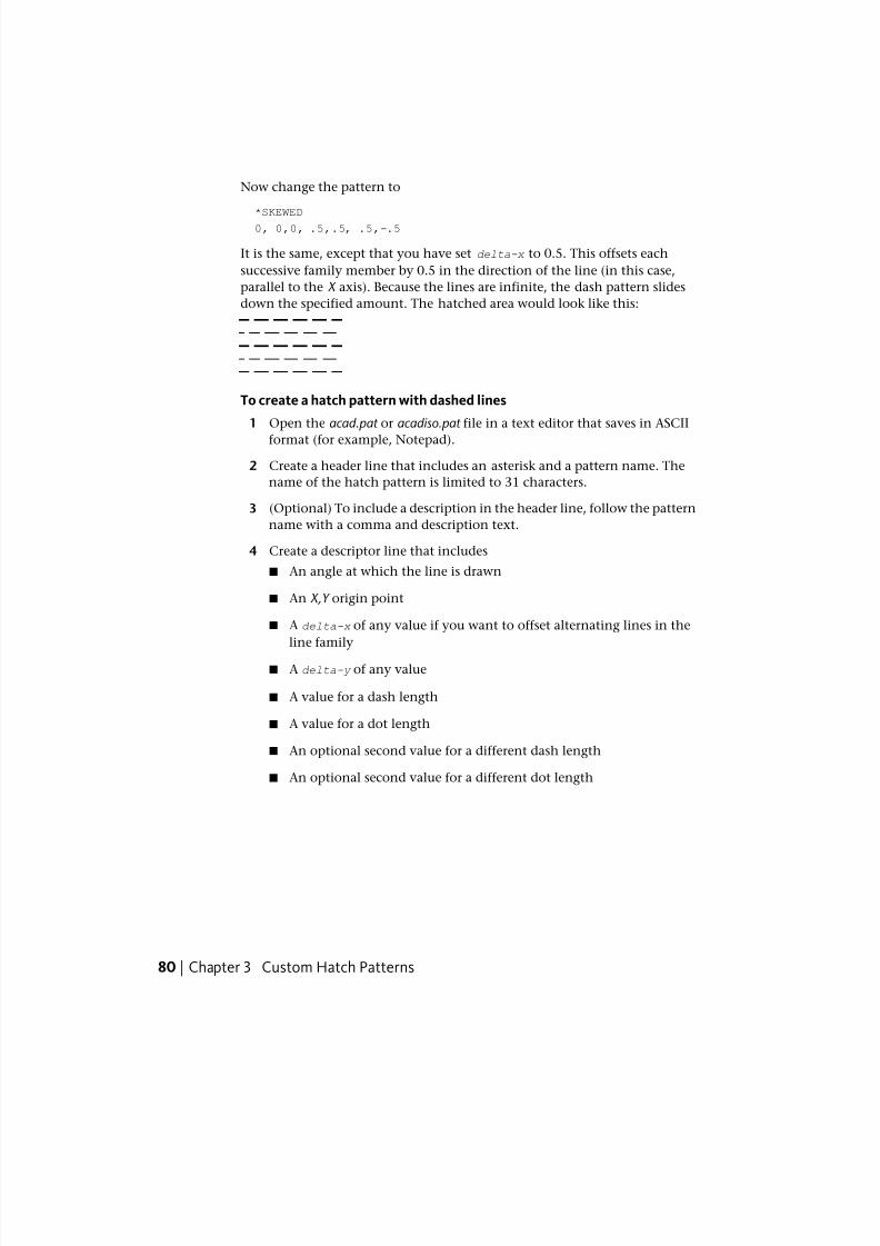
7/23/2019 Acad Customization
http://slidepdf.com/reader/full/acad-customization 88/553
Now change the pattern to
*SKEWED0, 0,0, .5,.5, .5,-.5
It is the same, except that you have set delta-x to 0.5. This offsets each
successive family member by 0.5 in the direction of the line (in this case,
parallel to the X axis). Because the lines are infinite, the dash pattern slides
down the specified amount. The hatched area would look like this:
To create a hatch pattern with dashed lines
1 Open the acad.pat or acadiso.pat file in a text editor that saves in ASCII
format (for example, Notepad).
2 Create a header line that includes an asterisk and a pattern name. The
name of the hatch pattern is limited to 31 characters.
3 (Optional) To include a description in the header line, follow the pattern
name with a comma and description text.
4 Create a descriptor line that includes
■ An angle at which the line is drawn
■ An X,Y origin point
■ A delta-x of any value if you want to offset alternating lines in the
line family
■ A delta-y of any value
■ A value for a dash length
■ A value for a dot length
■ An optional second value for a different dash length
■ An optional second value for a different dot length
80 | Chapter 3 Custom Hatch Patterns
7/23/2019 Acad Customization
http://slidepdf.com/reader/full/acad-customization 89/553
Quick Reference
Commands
ADCENTER
Manages and inserts content such as blocks, xrefs, and hatch patterns.
FILL
Controls the filling of objects such as hatches, 2D solids, and wide polylines.
HATCH
Fills an enclosed area or selected objects with a hatch pattern, solid fill, or
gradient fill.
HATCHEDIT
Modifies an existing hatch or fill.
SOLID
Creates solid-filled triangles and quadrilaterals.
System Variables
FILLMODE
Specifies whether hatches and fills, 2D solids, and wide polylines are filled
in.
HPANG
Sets the angle for new hatch patterns.
HPBOUND
Controls the object type created by HATCH and BOUNDARY.
HPDOUBLE
Specifies hatch pattern doubling for user-defined patterns.
HPNAME
Sets the default hatch pattern name.
HPSCALE
Sets the hatch pattern scale factor.
Hatch Patterns with Dashed Lines | 81
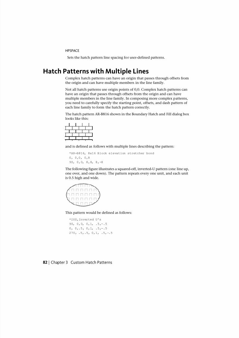
7/23/2019 Acad Customization
http://slidepdf.com/reader/full/acad-customization 90/553
HPSPACE
Sets the hatch pattern line spacing for user-defined patterns.
Hatch Patterns with Multiple LinesComplex hatch patterns can have an origin that passes through offsets from
the origin and can have multiple members in the line family.
Not all hatch patterns use origin points of 0,0. Complex hatch patterns can
have an origin that passes through offsets from the origin and can have
multiple members in the line family. In composing more complex patterns,
you need to carefully specify the starting point, offsets, and dash pattern of
each line family to form the hatch pattern correctly.
The hatch pattern AR-B816 shown in the Boundary Hatch and Fill dialog box
looks like this:
and is defined as follows with multiple lines describing the pattern:
*AR-B816, 8x16 Block elevation stretcher bond
0, 0,0, 0,8
90, 0,0, 8,8, 8,-8
The following figure illustrates a squared-off, inverted-U pattern (one line up,
one over, and one down). The pattern repeats every one unit, and each unit
is 0.5 high and wide.
This pattern would be defined as follows:
*IUS,Inverted U's
90, 0,0, 0,1, .5,-.5
0, 0,.5, 0,1, .5,-.5
270, .5,.5, 0,1, .5,-.5
82 | Chapter 3 Custom Hatch Patterns
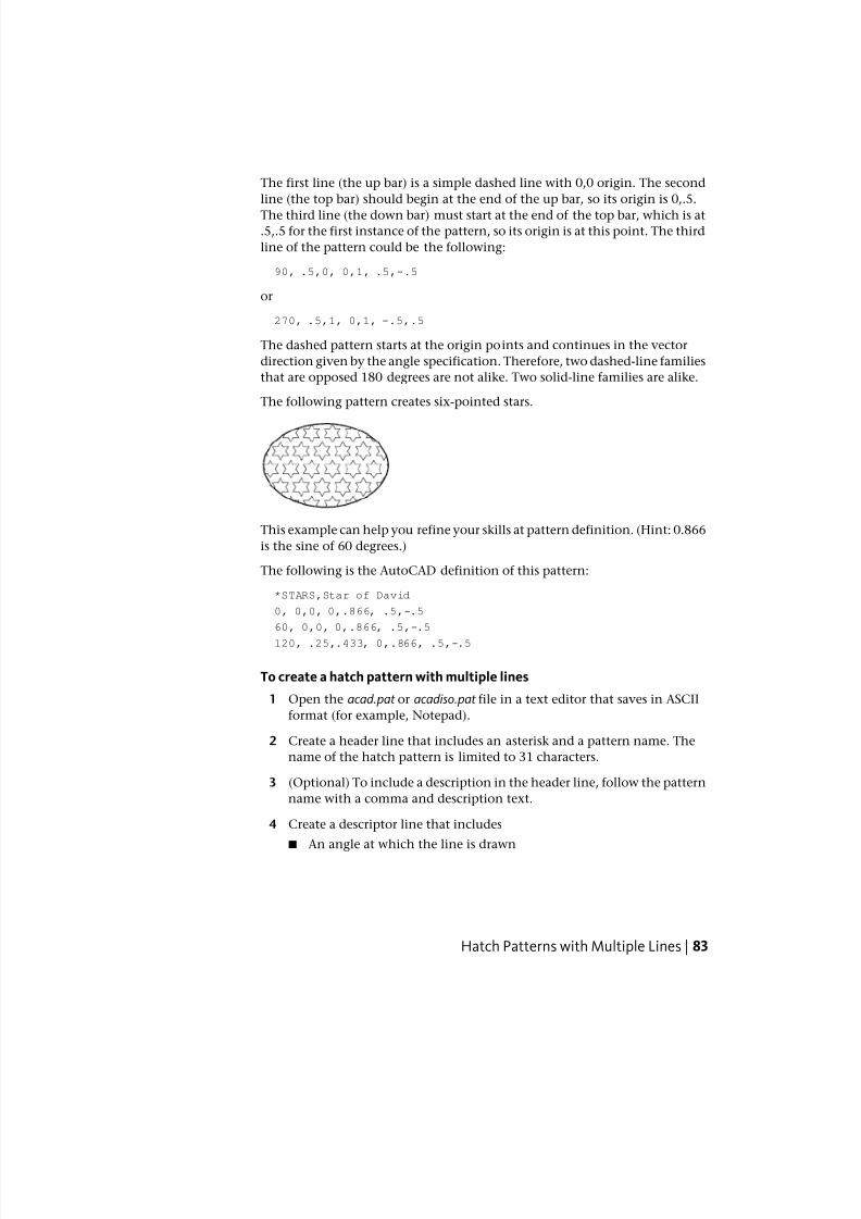
7/23/2019 Acad Customization
http://slidepdf.com/reader/full/acad-customization 91/553
The first line (the up bar) is a simple dashed line with 0,0 origin. The second
line (the top bar) should begin at the end of the up bar, so its origin is 0,.5.
The third line (the down bar) must start at the end of the top bar, which is at.5,.5 for the first instance of the pattern, so its origin is at this point. The third
line of the pattern could be the following:
90, .5,0, 0,1, .5,-.5
or
270, .5,1, 0,1, -.5,.5
The dashed pattern starts at the origin points and continues in the vector
direction given by the angle specification. Therefore, two dashed-line families
that are opposed 180 degrees are not alike. Two solid-line families are alike.
The following pattern creates six-pointed stars.
This example can help you refine your skills at pattern definition. (Hint: 0.866
is the sine of 60 degrees.)
The following is the AutoCAD definition of this pattern:
*STARS,Star of David
0, 0,0, 0,.866, .5,-.5
60, 0,0, 0,.866, .5,-.5
120, .25,.433, 0,.866, .5,-.5
To create a hatch pattern with multiple lines
1 Open the acad.pat or acadiso.pat file in a text editor that saves in ASCII
format (for example, Notepad).
2 Create a header line that includes an asterisk and a pattern name. The
name of the hatch pattern is limited to 31 characters.
3 (Optional) To include a description in the header line, follow the pattern
name with a comma and description text.
4 Create a descriptor line that includes
■ An angle at which the line is drawn
Hatch Patterns with Multiple Lines | 83
7/23/2019 Acad Customization
http://slidepdf.com/reader/full/acad-customization 92/553
■ An X,Y origin point
■ A delta-x of any value if you want to offset alternating lines in the linefamily
■ A delta-y of any value
■ A value for a dash length
■ A value for a dot length
■ An optional second value for a different dash length
■ An optional second value for a different dot length
5 Create a second line including all the parameters in the previous step.
6 (Optional) Create additional lines to complete the multiple-line hatch
pattern.
Quick Reference
Commands
ADCENTER
Manages and inserts content such as blocks, xrefs, and hatch patterns.
FILL
Controls the filling of objects such as hatches, 2D solids, and wide polylines.
HATCH
Fills an enclosed area or selected objects with a hatch pattern, solid fill, or
gradient fill.
HATCHEDIT
Modifies an existing hatch or fill.
SOLID
Creates solid-filled triangles and quadrilaterals.
84 | Chapter 3 Custom Hatch Patterns
7/23/2019 Acad Customization
http://slidepdf.com/reader/full/acad-customization 93/553
System Variables
FILLMODESpecifies whether hatches and fills, 2D solids, and wide polylines are filled
in.
HPANG
Sets the angle for new hatch patterns.
HPBOUND
Controls the object type created by HATCH and BOUNDARY.
HPDOUBLE
Specifies hatch pattern doubling for user-defined patterns.
HPNAME
Sets the default hatch pattern name.
HPSCALE
Sets the hatch pattern scale factor.
HPSPACE
Sets the hatch pattern line spacing for user-defined patterns.
Hatch Patterns with Multiple Lines | 85

7/23/2019 Acad Customization
http://slidepdf.com/reader/full/acad-customization 94/553
86
7/23/2019 Acad Customization
http://slidepdf.com/reader/full/acad-customization 95/553
User InterfaceCustomization
When you work in the program, you use a variety of ribbon panels, menus, toolbars, shortcutkeys, and other user interface elements to help you accomplish your tasks efficiently. You
can also streamline your environment by customizing these elements.
Understand User Interface CustomizationUsing the customization tools of AutoCAD, you can tailor your drawing
environment to suit your needs. Customization capabilities, including the
customize (CUIx) file format and the Customize User Interface (CUI) Editor,
help you to easily create and modify customized content.
Overview of the Customization
Customization of the user interface is done by modifying the XML-based CUIx
file with the Customize User Interface (CUI) Editor. The XML-based CUIx file
replaces the customization and menu files from releases prior to AutoCAD 2011.
Instead of using a text editor to customize menu files (MNU and MNS files) used
in release prior to AutoCAD 2006, you customize the user interface from within
AutoCAD. You can
■ Add or change toolbars, menus, and ribbon panels (including shortcut
menus, image tile menus, and tablet menus)
■ Add and modify the commands on the Quick Access toolbar
■ Create or change workspaces
■ Assign commands to various user interface elements
4
87
7/23/2019 Acad Customization
http://slidepdf.com/reader/full/acad-customization 96/553
■ Create or change macros
■ Define DIESEL strings
■ Create or change aliases
■ Add descriptive text for command tooltips
■ Control the properties displayed when using rollover tooltips
Customizable User Interface Elements
The editor allows you to create and manage commands that are used in the
CUIx file in a centralized location. Along with commands, you are able to
customize many of the different user interface elements. From the CUI Editor
you can customize
■ Double click actions
■ Legacy user interface elements (tablets, tablet buttons, screen menus and
image tile menus)
■ Mouse buttons
■ Pull-down menus
■ Quick Access toolbar
■ Quick properties
■ Toolbars
■ Ribbon panels
■ Ribbon tabs
■ Ribbon contextual tab states
■ Rollover tooltips
■ Shortcut keys
■ Shortcut menus
■ Temporary override keys
■ Workspaces
88 | Chapter 4 User Interface Customization
7/23/2019 Acad Customization
http://slidepdf.com/reader/full/acad-customization 97/553

7/23/2019 Acad Customization
http://slidepdf.com/reader/full/acad-customization 98/553
Use the Customization EnvironmentYou customize the XML-based CUIx file with the Customize User Interface(CUI) Editor to create new commands, user interface elements, and workspaces.
Overview of the Customize User Interface (CUI) Editor
The Customize User Interface (CUI) Editor is used to customize the user
interface of AutoCAD. Before you start customizing your own menus, toolbars,
and other user interface elements, you should familiarize yourself with the
customization environment.
To open the Customize User Interface Editor, click Manage tab ➤ Customization panel ➤ User Interface. Once the Customize User Interface
(CUI) Editor is opened, view the contents of the loaded customization files
by expanding the elements in the tree structure, and view the properties of
the elements by selecting them.
Select the Transfer tab to see how to migrate or transfer customizations; select
the Customize tab to see how to create or modify user interface elements.
Once you are familiar with the environment, you can start to take advantage
of the capabilities of the tools. For more information about the improved
customization capabilities, see How Customization Has Changed on page 96.
Following is an example of the Customize User Interface (CUI) Editor,
Customize tab. You use this tab to customize interface elements in CUIx files.
90 | Chapter 4 User Interface Customization
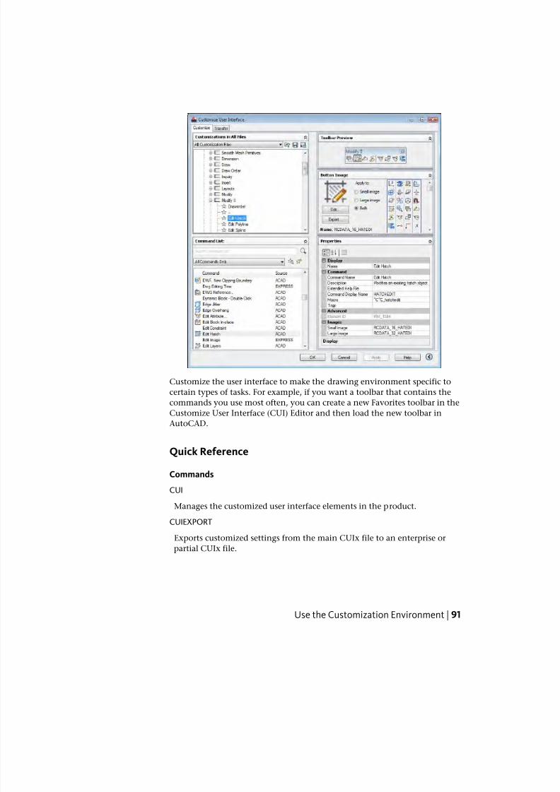
7/23/2019 Acad Customization
http://slidepdf.com/reader/full/acad-customization 99/553
Customize the user interface to make the drawing environment specific to
certain types of tasks. For example, if you want a toolbar that contains the
commands you use most often, you can create a new Favorites toolbar in the
Customize User Interface (CUI) Editor and then load the new toolbar inAutoCAD.
Quick Reference
Commands
CUI
Manages the customized user interface elements in the product.
CUIEXPORT
Exports customized settings from the main CUIx file to an enterprise or
partial CUIx file.
Use the Customization Environment | 91
7/23/2019 Acad Customization
http://slidepdf.com/reader/full/acad-customization 100/553
CUIIMPORT
Imports customized settings from an enterprise or partial CUIx file to themain CUIx file.
CUILOAD
Loads a CUIx file.
CUIUNLOAD
Unloads a CUIx file.
QUICKCUI
Displays the Customize User Interface Editor in a collapsed state.
System Variables
DBLCLKEDIT
Controls the double click editing behavior in the drawing area.
ENTERPRISEMENU
Stores the enterprise customization file name (if defined), including the path
for the file name.
MENUNAME
Stores the customization file name, including the path for the file name.
TOOLTIPS
Controls the display of tooltips on the ribbon, toolbars, and other user
interface elements.
Work with the Customizations In PaneThe Customizations In pane is used to navigate the different user interface
elements that are in the loaded customization files.
In this pane, you create and modify user interface elements such as workspaces,
toolbars, and menus. Along the top of the pane you will find tools that load
partial customization files into the main customization file, save changes to
the loaded customization files, and control how you view the loaded
customization files.
The tree view is used to create new user interface elements such as toolbars
and menus. Once a new user interface element is created, commands can thenbe added by dragging them from the Command List pane. Along with being
92 | Chapter 4 User Interface Customization
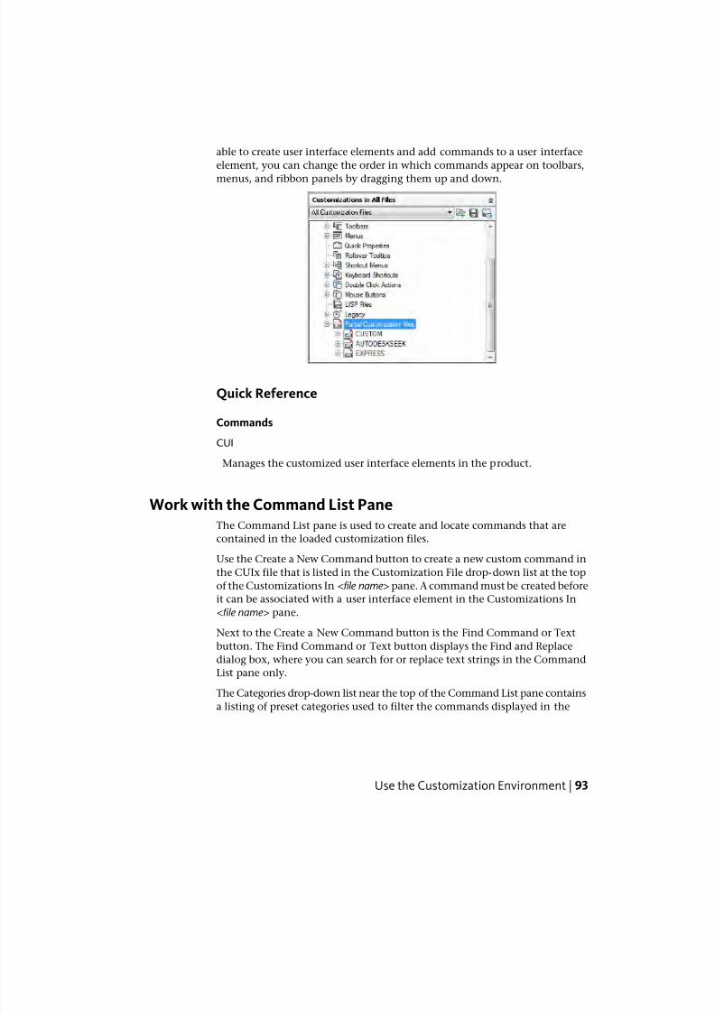
7/23/2019 Acad Customization
http://slidepdf.com/reader/full/acad-customization 101/553
able to create user interface elements and add commands to a user interface
element, you can change the order in which commands appear on toolbars,
menus, and ribbon panels by dragging them up and down.
Quick Reference
Commands
CUI
Manages the customized user interface elements in the product.
Work with the Command List PaneThe Command List pane is used to create and locate commands that are
contained in the loaded customization files.
Use the Create a New Command button to create a new custom command in
the CUIx file that is listed in the Customization File drop-down list at the top
of the Customizations In <file name> pane. A command must be created before
it can be associated with a user interface element in the Customizations In
<file name> pane.
Next to the Create a New Command button is the Find Command or Text
button. The Find Command or Text button displays the Find and Replace
dialog box, where you can search for or replace text strings in the Command
List pane only.
The Categories drop-down list near the top of the Command List pane contains
a listing of preset categories used to filter the commands displayed in the
Use the Customization Environment | 93
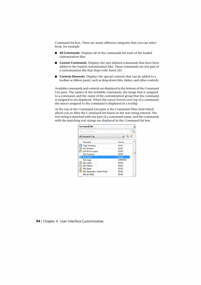
7/23/2019 Acad Customization
http://slidepdf.com/reader/full/acad-customization 102/553
7/23/2019 Acad Customization
http://slidepdf.com/reader/full/acad-customization 103/553
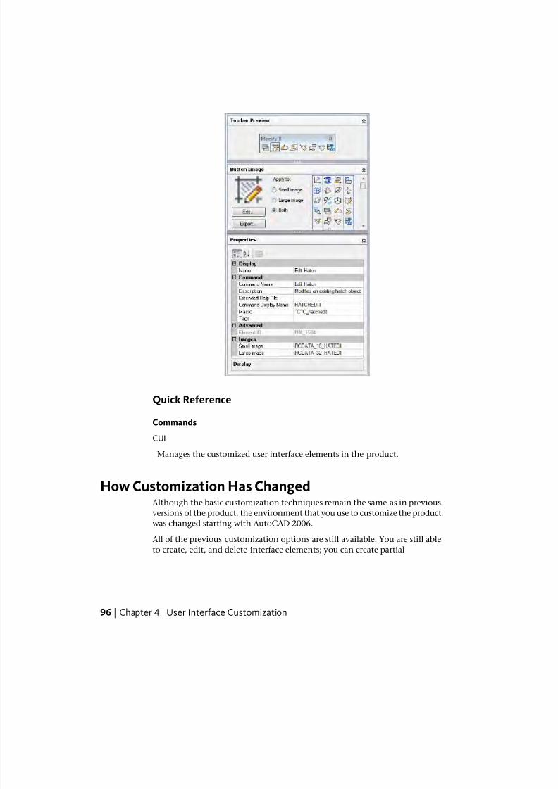
7/23/2019 Acad Customization
http://slidepdf.com/reader/full/acad-customization 104/553
Quick Reference
Commands
CUI
Manages the customized user interface elements in the product.
How Customization Has ChangedAlthough the basic customization techniques remain the same as in previous
versions of the product, the environment that you use to customize the product
was changed starting with AutoCAD 2006.
All of the previous customization options are still available. You are still able
to create, edit, and delete interface elements; you can create partial
96 | Chapter 4 User Interface Customization
7/23/2019 Acad Customization
http://slidepdf.com/reader/full/acad-customization 105/553
customization files; you can use macros and advanced entries such as DIESEL
expressions and AutoLISP routines.
However, you no longer perform customization tasks by creating or editing
MNU or MNS text files by hand. All customizations are done through the
program interface, in the Customize User Interface (CUI) Editor.
Menu Files Versus Customization Files
In releases prior to AutoCAD 2006, you customized the user interface by editing
an MNU or MNS file in an ASCII text editor such as Notepad. You manually
entered and verified customization data in the text file, which could be a
tedious and error-prone process. As a result, a simple syntax error (such as
mismatched parentheses) in the text file could invalidate the entire menu file,
leading you back to the text file to investigate where you made the error.
With the Customize User Interface (CUI) Editor, you drag a command to a
menu or toolbar or right-click to add, delete, or modify a user interface element.
The Customize User Interface (CUI) Editor displays element properties and a
list of options to choose from. This prevents you from creating syntax errors
or spelling mistakes that may have occurred when you manually entered text
in an MNU or MNS file.
The MNU and MNS files used in the past have been replaced with just one
file type, the XML-based CUIx file. CUIx is the successor to the CUI file format
which was introduced in AutoCAD 2006.
The XML-based format of the CUIx file allows the product to track
customizations. When upgrading to a future version of the program, all of
your customizations are automatically integrated into the new release. The
XML format also supports a backward-compatible customization file. This
means that you can view a CUIx file from a future version in the previousrelease while preserving the customization data from the future version.
However, you cannot modify the future version's CUIx file in the previous
release. For more information about migrating customization data, see Transfer
and Migrate Customization on page 384.
The following table lists the menu files that previously shipped with the
product and shows how those files are mapped to AutoCAD 2011.
Menu files mapped to CUIx files
Description of changeIn Auto-CAD 2011
DescriptionMenu file
An XML file that defines
most user interface ele-
CUIx ASCII text file. In previous re-
leases, defined most user inter-
MNU
How Customization Has Changed | 97
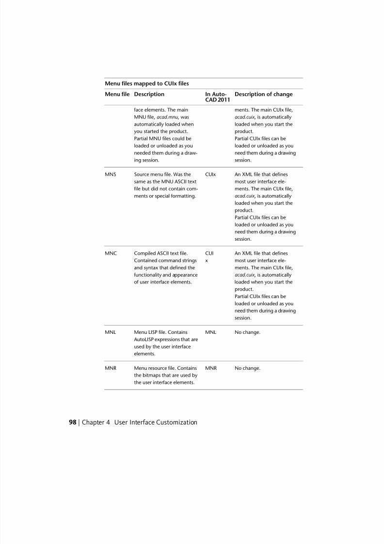
7/23/2019 Acad Customization
http://slidepdf.com/reader/full/acad-customization 106/553
Menu files mapped to CUIx files
Description of changeIn Auto-CAD 2011DescriptionMenu file
ments. The main CUIx file,
acad.cuix , is automatically
face elements. The main
MNU file, acad.mnu , was
loaded when you start the
product.
automatically loaded when
you started the product.
Partial CUIx files can be
loaded or unloaded as you
Partial MNU files could be
loaded or unloaded as you
need them during a drawing
session.
needed them during a draw-
ing session.
An XML file that defines
most user interface ele-
CUIxSource menu file. Was the
same as the MNU ASCII text
MNS
ments. The main CUIx file, file but did not contain com-ments or special formatting. acad.cuix , is automatically
loaded when you start the
product.
Partial CUIx files can be
loaded or unloaded as you
need them during a drawing
session.
An XML file that defines
most user interface ele-
CUI
x
Compiled ASCII text file.
Contained command strings
MNC
ments. The main CUIx file,and syntax that defined the
acad.cuix , is automatically functionality and appearance
of user interface elements. loaded when you start the
product.
Partial CUIx files can be
loaded or unloaded as you
need them during a drawing
session.
No change.MNLMenu LISP file. Contains
AutoLISP expressions that are
MNL
used by the user interface
elements.
No change.MNRMenu resource file. Contains
the bitmaps that are used by
the user interface elements.
MNR
98 | Chapter 4 User Interface Customization
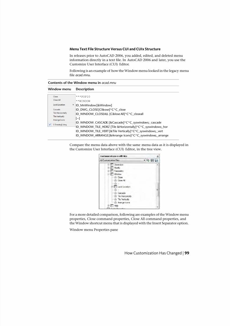
7/23/2019 Acad Customization
http://slidepdf.com/reader/full/acad-customization 107/553
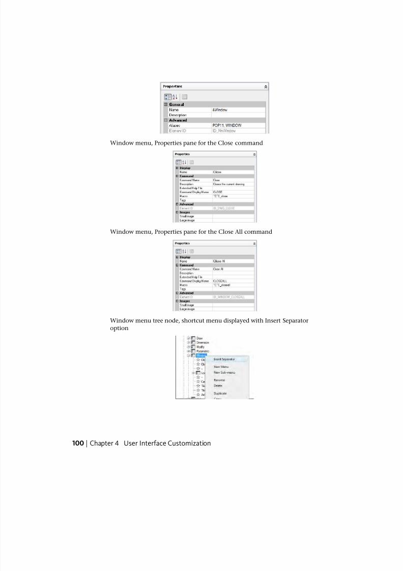
7/23/2019 Acad Customization
http://slidepdf.com/reader/full/acad-customization 108/553
Window menu, Properties pane for the Close command
Window menu, Properties pane for the Close All command
Window menu tree node, shortcut menu displayed with Insert Separator
option
100 | Chapter 4 User Interface Customization
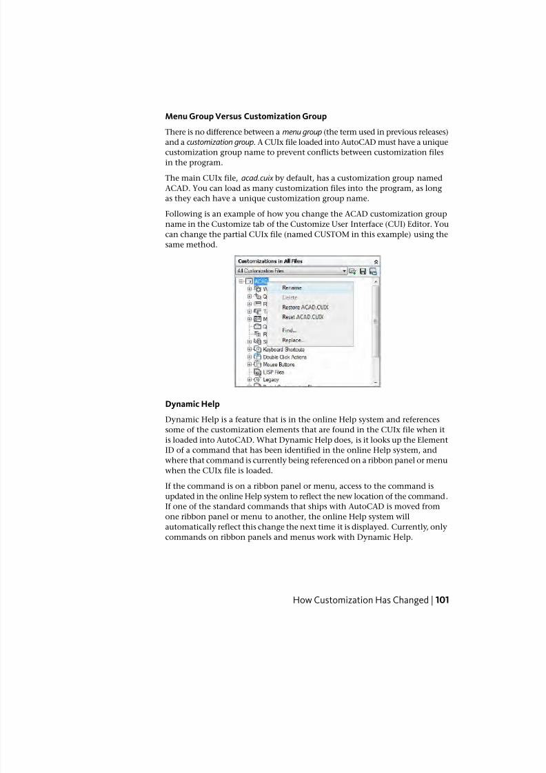
7/23/2019 Acad Customization
http://slidepdf.com/reader/full/acad-customization 109/553
Menu Group Versus Customization Group
There is no difference between a menu group (the term used in previous releases)and a customization group. A CUIx file loaded into AutoCAD must have a unique
customization group name to prevent conflicts between customization files
in the program.
The main CUIx file, acad.cuix by default, has a customization group named
ACAD. You can load as many customization files into the program, as long
as they each have a unique customization group name.
Following is an example of how you change the ACAD customization group
name in the Customize tab of the Customize User Interface (CUI) Editor. You
can change the partial CUIx file (named CUSTOM in this example) using the
same method.
Dynamic HelpDynamic Help is a feature that is in the online Help system and references
some of the customization elements that are found in the CUIx file when it
is loaded into AutoCAD. What Dynamic Help does, is it looks up the Element
ID of a command that has been identified in the online Help system, and
where that command is currently being referenced on a ribbon panel or menu
when the CUIx file is loaded.
If the command is on a ribbon panel or menu, access to the command is
updated in the online Help system to reflect the new location of the command.
If one of the standard commands that ships with AutoCAD is moved from
one ribbon panel or menu to another, the online Help system will
automatically reflect this change the next time it is displayed. Currently, only
commands on ribbon panels and menus work with Dynamic Help.
How Customization Has Changed | 101
7/23/2019 Acad Customization
http://slidepdf.com/reader/full/acad-customization 110/553
Dynamic Help may not display properly if a command is not available:
■ In one of the loaded CUIx files
■ On an accessible menu, ribbon panel, or ribbon tab in the current
workspace
NOTE Dynamic Help only works with the online Help documents that come with
AutoCAD, and has no affect on third-party documentation.
See also:
■ Transfer and Migrate Customization on page 384
■ Create and Load a Partial CUIx File on page 127
■ Create an Enterprise CUIx File on page 131
Quick Reference
Commands
CUI
Manages the customized user interface elements in the product.
CUIEXPORT
Exports customized settings from the main CUIx file to an enterprise or
partial CUIx file.
CUIIMPORT
Imports customized settings from an enterprise or partial CUIx file to the
main CUIx file.
CUILOAD
Loads a CUIx file.
CUIUNLOAD
Unloads a CUIx file.
QUICKCUI
Displays the Customize User Interface Editor in a collapsed state.
102 | Chapter 4 User Interface Customization
7/23/2019 Acad Customization
http://slidepdf.com/reader/full/acad-customization 111/553
Customization GlossaryYou should know several terms for customizing AutoCAD 2011.
Customization (CUIx) file A package file that contains multiple XML-based
files and custom image files. Each one of the XML-based files contain the data
for a different type of user interface element that can be customized. The
custom images that are stored in the file are those that are referenced by the
commands defined in the customization data and are not stored in a resource
DLL. You modify a customization file through the Customize User Interface
(CUI) Editor. CUIx files replace the CUI, MNU, MNS, and MNC files that were
used to define menus in releases prior to AutoCAD 2011.
Customization group A name that is assigned to a CUIx file to identify
customization content in the CUIx file. A CUIx file loaded into AutoCAD
must have a unique customization group name to prevent conflicts between
CUIx files in the program. In releases prior to AutoCAD 2006, called amenugroup.
Element ID A unique identifier of an interface element. In previous releases,
called a tag .
Dashboard panel An organizational structure used to lay out commands and
controls for display on the dashboard, which was available in AutoCAD 2007
and AutoCAD 2008. The dashboard was replaced by the ribbon in AutoCAD
2009 and later. For information about transferring dashboard panels to ribbon
panels, see To copy a dashboard panel to a ribbon panel on page 204.
Enterprise customization file A CUIx file that is typically controlled by a
CAD manager. It is often accessed by many users and is stored in a shared
network location. The file is read-only to users to prevent the data in the file
from being changed. A CAD manager creates an enterprise CUIx file by
modifying a main CUIx file and then saving the file to a shared network
location. Users then specify this file in the Options dialog box, Files tab.
Interface element An object that can be customized, such as a toolbar,
pull-down menu, shortcut key, palette, and so on. It is a node in the
Customizations In <file name> pane that contains user interface items.
Interface item The individual parts of a user interface element, such as a
toolbar button, pull-down menu item, shortcut key, temporary override key,
and so on.
Legacy Customization (CUI) file An XML-based file that stores customization
data for AutoCAD 2006 through AutoCAD 2009. The CUI file has been replaced
by the CUIx file. A CUIx file can be generated from a CUI file using the Transfertab of the CUI command.
Customization Glossary | 103

7/23/2019 Acad Customization
http://slidepdf.com/reader/full/acad-customization 112/553
Legacy Menu (MNS) file An ASCII based file that stores menu customization
data for AutoCAD 2005 and earlier. Most of the file needed to be edited outside
of AutoCAD using a text editor such as Notepad, but there were a few featuresthat could be customized in AutoCAD using the CUSTOMIZE command. The
MNS file has been replaced by the CUIx file. A CUIx file can be generated from
an MNS file using the Transfer tab of the CUI command.
Legacy Menu Template (MNU) file An ASCII based file that is used as a
template to define the contents of the MNS file when the MNU file is loaded
into AutoCAD with the MENU command. The MNU file is used in AutoCAD
2005 and earlier, and is very similar to the MNS file. The MNU file has been
replaced by the CUIx file. A CUIx file can be generated from a MNU file using
the Transfer tab of the CUI command.
Macro A series of commands that are run in a defined sequence to accomplish
a drawing task.
Main customization file A writable CUIx file that defines most of the user
interface elements (including the standard menus, toolbars, keyboard
accelerators, and so on). The acad.cuix file (the default main CUIx file) is
automatically loaded when you start AutoCAD.
Ribbon An interface element that displays panels made up of commands and
controls that can be docked horizontally or vertically along the program’s
application window.
Ribbon panel An organizational structure used to lay out commands and
controls for display on the ribbon or as a floating user interface.
Palette An interface element that can be docked or floating in the drawing
area. Palettes include the Command Line window, Tool Palettes Window,
Properties palette, and so on.
Partial customization file Any CUIx file that is not defined as the main or
enterprise CUIx file. You can load and unload partial CUIx files as you need
them during a drawing session.
Quick Access toolbar An interface element that is located to the right of the
application menu and provides direct access to a defined set of commands.
Tree node A hierarchical structure in the Customize User Interface (CUI)
Editor that contains interface elements and items that can be imported,
exported, and customized.
Workspace A collection of user interface elements, including their contents,
properties, display states, and locations.
104 | Chapter 4 User Interface Customization
7/23/2019 Acad Customization
http://slidepdf.com/reader/full/acad-customization 113/553
Quick Reference
Commands
CUI
Manages the customized user interface elements in the product.
CUIEXPORT
Exports customized settings from the main CUIx file to an enterprise or
partial CUIx file.
CUIIMPORT
Imports customized settings from an enterprise or partial CUIx file to the
main CUIx file.
CUILOADLoads a CUIx file.
CUIUNLOAD
Unloads a CUIx file.
CUSTOMIZE
Customizes tool palettes and tool palette groups.
QUICKCUI
Displays the Customize User Interface Editor in a collapsed state.
RIBBON
Opens the ribbon window.
RIBBONCLOSE
Closes the ribbon window.
TOOLPALETTES
Opens the Tool Palettes window.
TOOLPALETTESCLOSE
Closes the Tool Palettes window.
Customization Glossary | 105
7/23/2019 Acad Customization
http://slidepdf.com/reader/full/acad-customization 114/553
System Variables
DBLCLKEDITControls the double click editing behavior in the drawing area.
ENTERPRISEMENU
Stores the enterprise customization file name (if defined), including the path
for the file name.
MENUNAME
Stores the customization file name, including the path for the file name.
ROLLOVERTIPS
Controls the display of rollover tooltips in the application.
TOOLTIPS
Controls the display of tooltips on the ribbon, toolbars, and other user
interface elements.
Work with the Customize User Interface (CUI)Editor
With the Customize User Interface (CUI) Editor, you can create and manage
standard and custom commands and user interface elements.
By customizing the user interface, you can arrange and access the commands
that you frequently use. You can also extend AutoCAD by creating your own
custom commands. Use the diagrams under this topic to understand the stepsrequired to successfully create a custom command or to customize the various
user interface elements that are available for customization.
Create a CommandCustom commands to define a series of actions that should be taken when
the custom command is used. You can also determine how the command
should appear when added to a user interface.
When creating a custom command, you need to give the command a unique
name, element ID, and macro. Once the basic properties of a command have
been defined, you can assign values to additional properties that determine
the content for the command’s tooltip, an image, and search tags. For more
106 | Chapter 4 User Interface Customization
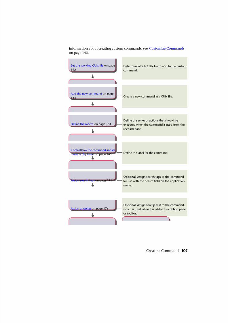
7/23/2019 Acad Customization
http://slidepdf.com/reader/full/acad-customization 115/553
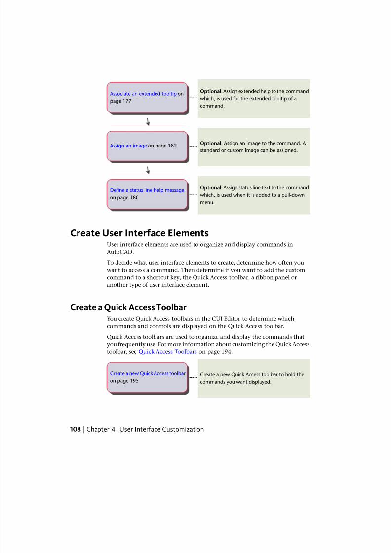
7/23/2019 Acad Customization
http://slidepdf.com/reader/full/acad-customization 116/553
Optional:Assign extended help to the command
which, is used for the extended tooltip of a
command.
----- Associate an extended tooltip on
page 177
Optional: Assign an image to the command. A
standard or custom image can be assigned.----- Assign an image on page 182
Optional: Assign status line text to the command
which, is used when it is added to a pull-down
menu.
-----Define a status line help message
on page 180
Create User Interface ElementsUser interface elements are used to organize and display commands in
AutoCAD.
To decide what user interface elements to create, determine how often you
want to access a command. Then determine if you want to add the custom
command to a shortcut key, the Quick Access toolbar, a ribbon panel or
another type of user interface element.
Create a Quick Access ToolbarYou create Quick Access toolbars in the CUI Editor to determine which
commands and controls are displayed on the Quick Access toolbar.
Quick Access toolbars are used to organize and display the commands that
you frequently use. For more information about customizing the Quick Access
toolbar, see Quick Access Toolbars on page 194.
Create a new Quick Access toolbar to hold the
commands you want displayed.-----
Create a new Quick Access toolbar
on page 195
108 | Chapter 4 User Interface Customization
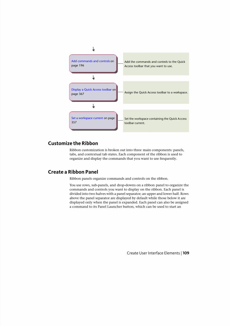
7/23/2019 Acad Customization
http://slidepdf.com/reader/full/acad-customization 117/553
Add the commands and controls to the Quick
Access toolbar that you want to use.-----
Add commands and controls on
page 196
Assign the Quick Access toolbar to a workspace.-----Display a Quick Access toolbar on
page 367
Set the workspace containing the Quick Access
toolbar current.-----
Set a workspace current on page
357
Customize the RibbonRibbon customization is broken out into three main components: panels,
tabs, and contextual tab states. Each component of the ribbon is used to
organize and display the commands that you want to use frequently.
Create a Ribbon PanelRibbon panels organize commands and controls on the ribbon.
You use rows, sub-panels, and drop-downs on a ribbon panel to organize the
commands and controls you want to display on the ribbon. Each panel is
divided into two halves with a panel separator; an upper and lower half. Rows
above the panel separator are displayed by default while those below it are
displayed only when the panel is expanded. Each panel can also be assigned
a command to its Panel Launcher button, which can be used to start an
Create User Interface Elements | 109
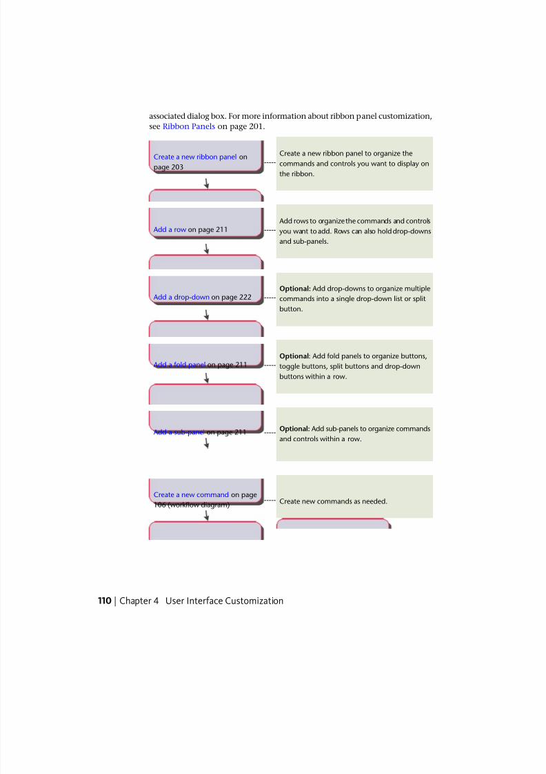
7/23/2019 Acad Customization
http://slidepdf.com/reader/full/acad-customization 118/553
associated dialog box. For more information about ribbon panel customization,
see Ribbon Panels on page 201.
Create a new ribbon panel to organize the
commands and controls you want to display on
the ribbon.
-----Create a new ribbon panel on
page 203
Add rows to organize the commands and controls
you want to add. Rows can also hold drop-downs
and sub-panels.
----- Add a row on page 211
Optional: Add drop-downs to organize multiple
commands into a single drop-down list or split
button.
----- Add a drop-down on page 222
Optional: Add fold panels to organize buttons,
toggle buttons, split buttons and drop-down
buttons within a row.
----- Add a fold panel on page 211
Optional: Add sub-panels to organize commands
and controls within a row.----- Add a sub-panel on page 211
Create new commands as needed.-----Create a new command on page
106 (workflow diagram)
110 | Chapter 4 User Interface Customization
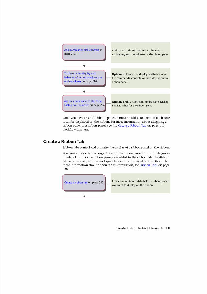
7/23/2019 Acad Customization
http://slidepdf.com/reader/full/acad-customization 119/553
Add commands and controls to the rows,sub-panels, and drop-downs on the ribbon panel.
----- Add commands and controls on
page 213
Optional: Change the display and behavior of
the commands, controls, or drop-downs on the
ribbon panel.
-----
To change the display and
behavior of a command, control
or drop-down on page 216
Optional: Add a command to the Panel DialogBox Launcher for the ribbon panel.
----- Assign a command to the Panel
Dialog Box Launcher on page 206
Once you have created a ribbon panel, it must be added to a ribbon tab before
it can be displayed on the ribbon. For more information about assigning a
ribbon panel to a ribbon panel, see the Create a Ribbon Tab on page 111
workflow diagram.
Create a Ribbon TabRibbon tabs control and organize the display of a ribbon panel on the ribbon.
You create ribbon tabs to organize multiple ribbon panels into a single groupof related tools. Once ribbon panels are added to the ribbon tab, the ribbon
tab must be assigned to a workspace before it is displayed on the ribbon. For
more information about ribbon tab customization, see Ribbon Tabs on page
238.
Create a new ribbon tab to hold the ribbon panels
you want to display on the ribbon.-----Create a ribbon tab on page 240
Create User Interface Elements | 111
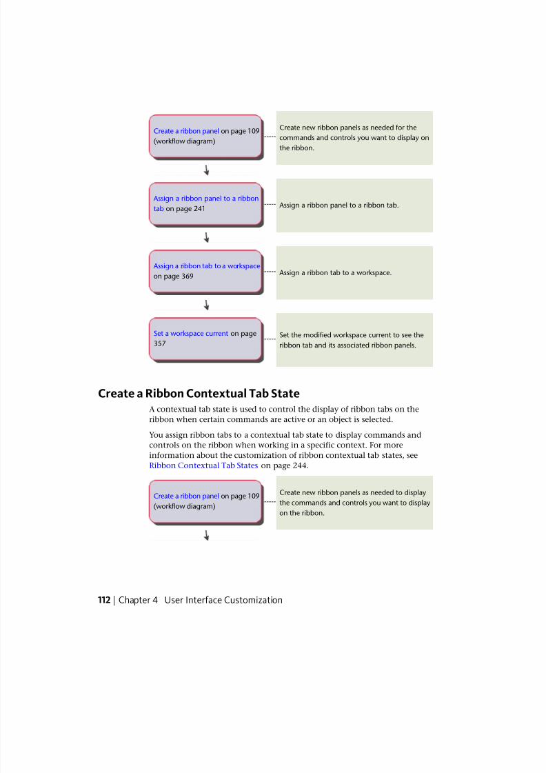
7/23/2019 Acad Customization
http://slidepdf.com/reader/full/acad-customization 120/553
Create new ribbon panels as needed for the
commands and controls you want to display on
the ribbon.
-----Create a ribbon panel on page 109
(workflow diagram)
Assign a ribbon panel to a ribbon tab.----- Assign a ribbon panel to a ribbon
tab on page 241
Assign a ribbon tab to a workspace.----- Assign a ribbon tab to a workspace
on page 369
Set the modified workspace current to see the
ribbon tab and its associated ribbon panels.-----
Set a workspace current on page
357
Create a Ribbon Contextual Tab StateA contextual tab state is used to control the display of ribbon tabs on theribbon when certain commands are active or an object is selected.
You assign ribbon tabs to a contextual tab state to display commands and
controls on the ribbon when working in a specific context. For more
information about the customization of ribbon contextual tab states, see
Ribbon Contextual Tab States on page 244.
Create new ribbon panels as needed to display
the commands and controls you want to display
on the ribbon.
-----Create a ribbon panel on page 109
(workflow diagram)
112 | Chapter 4 User Interface Customization
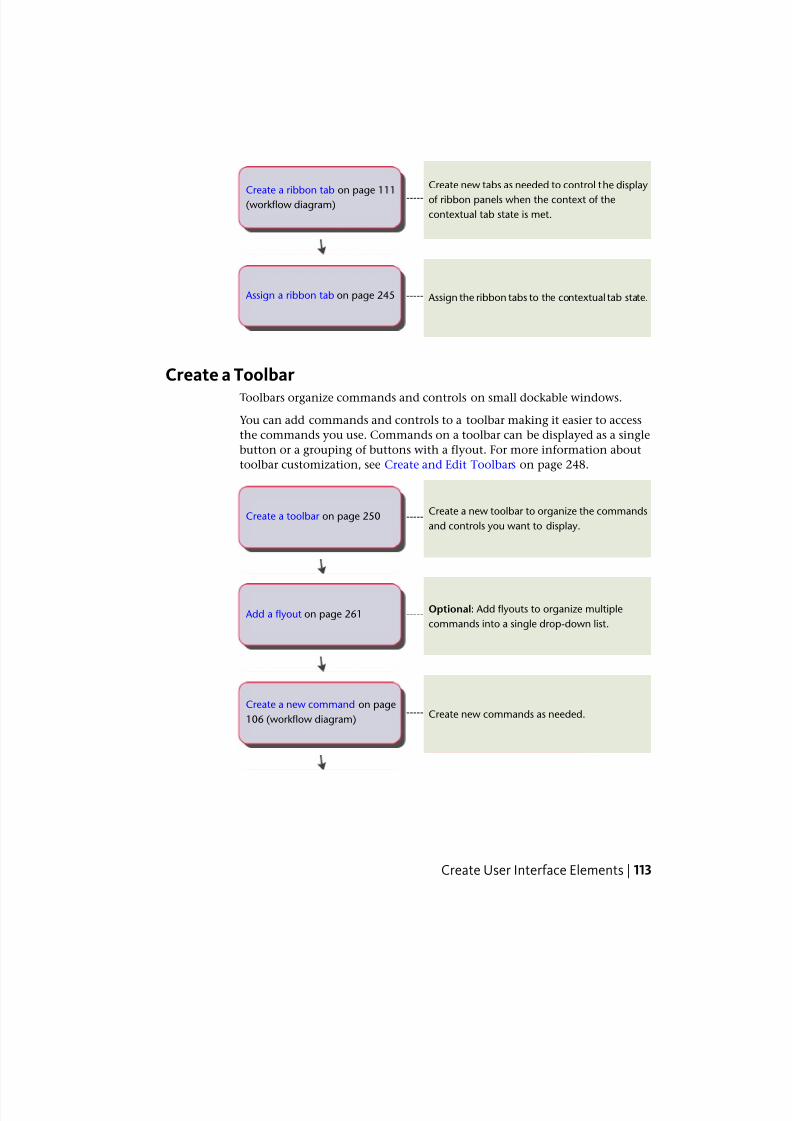
7/23/2019 Acad Customization
http://slidepdf.com/reader/full/acad-customization 121/553
Create new tabs as needed to control the display
of ribbon panels when the context of the
contextual tab state is met.
-----Create a ribbon tab on page 111
(workflow diagram)
Assign the ribbon tabs to the contextual tab state.----- Assign a ribbon tab on page 245
Create a ToolbarToolbars organize commands and controls on small dockable windows.
You can add commands and controls to a toolbar making it easier to access
the commands you use. Commands on a toolbar can be displayed as a single
button or a grouping of buttons with a flyout. For more information about
toolbar customization, see Create and Edit Toolbars on page 248.
Create a new toolbar to organize the commands
and controls you want to display.-----Create a toolbar on page 250
Optional: Add flyouts to organize multiple
commands into a single drop-down list.----- Add a flyout on page 261
Create new commands as needed.-----Create a new command on page
106 (workflow diagram)
Create User Interface Elements | 113
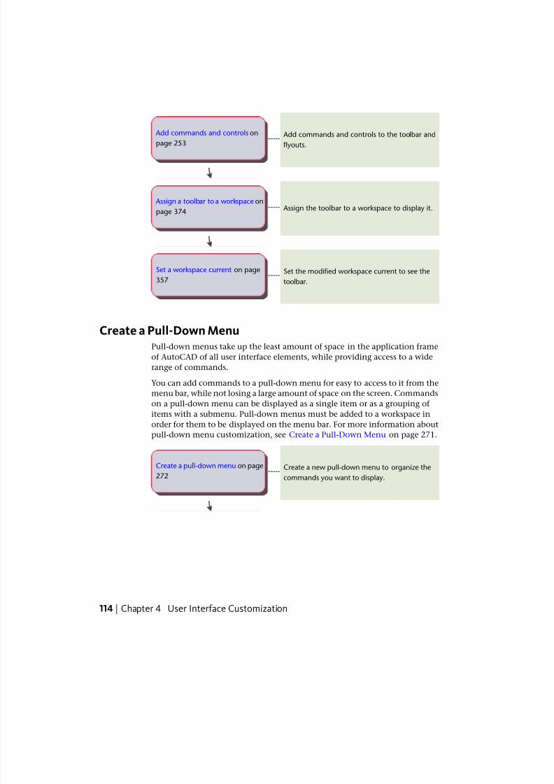
7/23/2019 Acad Customization
http://slidepdf.com/reader/full/acad-customization 122/553
Add commands and controls to the toolbar and flyouts.
----- Add commands and controls on
page 253
Assign the toolbar to a workspace to display it.----- Assign a toolbar to a workspace on
page 374
Set the modified workspace current to see thetoolbar.
-----Set a workspace current on page
357
Create a Pull-Down MenuPull-down menus take up the least amount of space in the application frame
of AutoCAD of all user interface elements, while providing access to a wide
range of commands.
You can add commands to a pull-down menu for easy to access to it from the
menu bar, while not losing a large amount of space on the screen. Commands
on a pull-down menu can be displayed as a single item or as a grouping of
items with a submenu. Pull-down menus must be added to a workspace inorder for them to be displayed on the menu bar. For more information about
pull-down menu customization, see Create a Pull-Down Menu on page 271.
Create a new pull-down menu to organize the
commands you want to display.-----
Create a pull-down menu on page
272
114 | Chapter 4 User Interface Customization
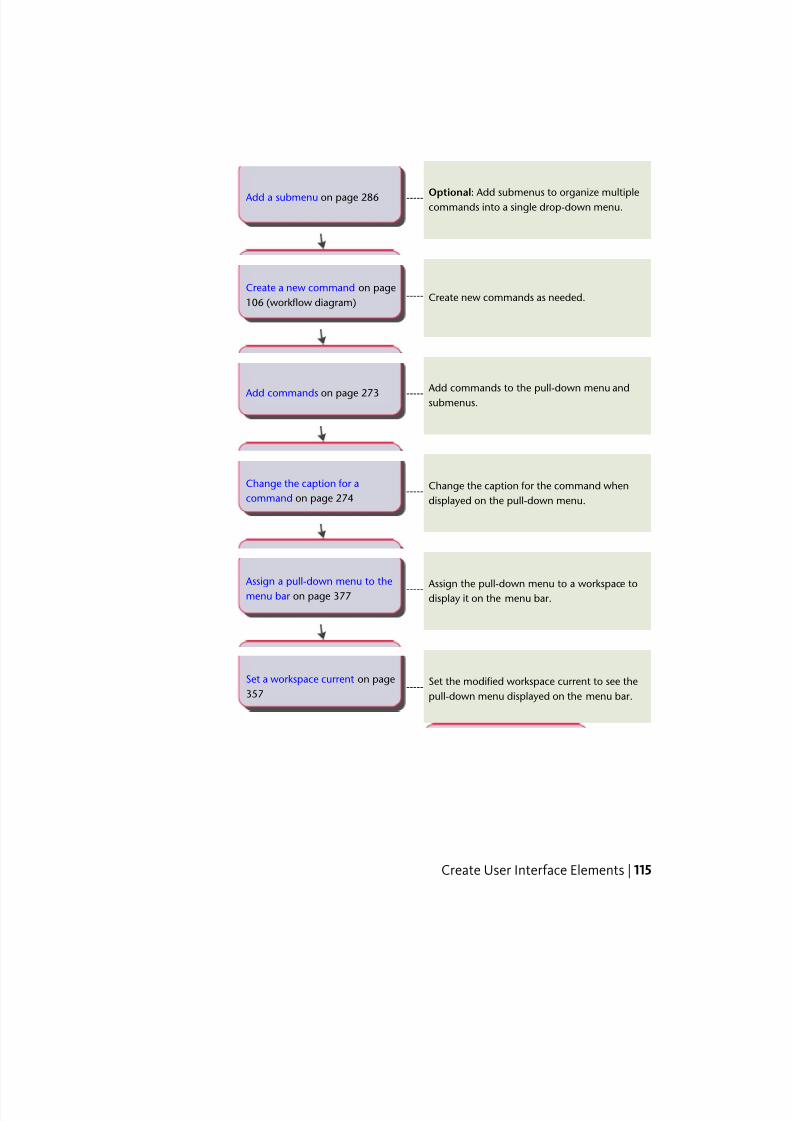
7/23/2019 Acad Customization
http://slidepdf.com/reader/full/acad-customization 123/553
Optional: Add submenus to organize multiplecommands into a single drop-down menu.
----- Add a submenu on page 286
Create new commands as needed.-----Create a new command on page
106 (workflow diagram)
Add commands to the pull-down menu andsubmenus.
----- Add commands on page 273
Change the caption for the command when
displayed on the pull-down menu.-----
Change the caption for a
command on page 274
Assign the pull-down menu to a workspace todisplay it on the menu bar.----- Assign a pull-down menu to the
menu bar on page 377
Set the modified workspace current to see the
pull-down menu displayed on the menu bar.-----
Set a workspace current on page
357
Create User Interface Elements | 115
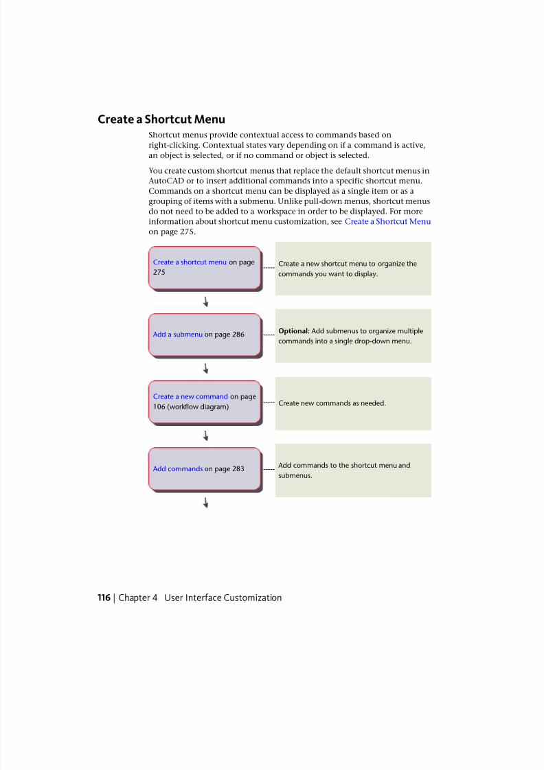
7/23/2019 Acad Customization
http://slidepdf.com/reader/full/acad-customization 124/553
Create a Shortcut Menu
Shortcut menus provide contextual access to commands based onright-clicking. Contextual states vary depending on if a command is active,
an object is selected, or if no command or object is selected.
You create custom shortcut menus that replace the default shortcut menus in
AutoCAD or to insert additional commands into a specific shortcut menu.
Commands on a shortcut menu can be displayed as a single item or as a
grouping of items with a submenu. Unlike pull-down menus, shortcut menus
do not need to be added to a workspace in order to be displayed. For more
information about shortcut menu customization, see Create a Shortcut Menu
on page 275.
Create a new shortcut menu to organize the
commands you want to display.-----
Create a shortcut menu on page
275
Optional: Add submenus to organize multiple
commands into a single drop-down menu.----- Add a submenu on page 286
Create new commands as needed.-----
Create a new command on page
106 (workflow diagram)
Add commands to the shortcut menu and
submenus.----- Add commands on page 283
116 | Chapter 4 User Interface Customization
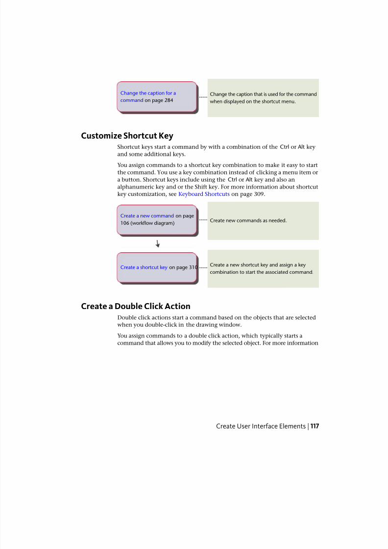
7/23/2019 Acad Customization
http://slidepdf.com/reader/full/acad-customization 125/553
Change the caption that is used for the commandwhen displayed on the shortcut menu.
-----Change the caption for a
command on page 284
Customize Shortcut KeyShortcut keys start a command by with a combination of the Ctrl or Alt key
and some additional keys.
You assign commands to a shortcut key combination to make it easy to start
the command. You use a key combination instead of clicking a menu item or
a button. Shortcut keys include using the Ctrl or Alt key and also an
alphanumeric key and or the Shift key. For more information about shortcut
key customization, see Keyboard Shortcuts on page 309.
Create new commands as needed.-----Create a new command on page
106 (workflow diagram)
Create a new shortcut key and assign a key
combination to start the associated command.-----Create a shortcut key on page 310
Create a Double Click ActionDouble click actions start a command based on the objects that are selected
when you double-click in the drawing window.
You assign commands to a double click action, which typically starts a
command that allows you to modify the selected object. For more information
Create User Interface Elements | 117
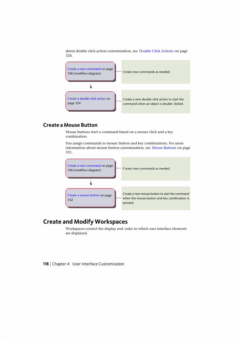
7/23/2019 Acad Customization
http://slidepdf.com/reader/full/acad-customization 126/553
about double click action customization, see Double Click Actions on page
324.
Create new commands as needed.-----Create a new command on page
106 (workflow diagram)
Create a new double click action to start the
command when an object is double clicked.-----
Create a double click action on
page 324
Create a Mouse ButtonMouse buttons start a command based on a mouse click and a key
combination.
You assign commands to mouse button and key combinations. For more
information about mouse button customization, see Mouse Buttons on page
331.
Create new commands as needed.-----Create a new command on page
106 (workflow diagram)
Create a new mouse button to start the command
when the mouse button and key combination is
pressed.
-----Create a mouse button on page
332
Create and Modify WorkspacesWorkspaces control the display and order in which user interface elements
are displayed.
118 | Chapter 4 User Interface Customization

7/23/2019 Acad Customization
http://slidepdf.com/reader/full/acad-customization 127/553
You create and manage workspaces from the user interface of AutoCAD or
with the Customize User Interface (CUI) Editor. Creating and managing
workspaces from the user interface is limited; the CUI Editor gives you fullcontrol over all user interface elements in a workspace. For more information
about workspace customization, see Customize Workspaces on page 347.
Create a Workspace from the User InterfaceYou can perform some basic customization of a workspace from the user
interface.
From the user interface, you can control the display of toolbars and palettes;
you can also add and remove commands from the Quick Access toolbar. You
can interactively update the position and display of both toolbars and palettes.
This cannot be done from the CUI Editor. For more information about
workspace customization from the user interface, see Control User InterfaceElements Outside the CUI Editor on page 361.
Create a new workspace from the user interface.-----Create a new workspace on page
352
Add and remove commands to and from the
Quick Access toolbar from the ribbon. You can
also add separators to group related commands.
-----
Add or remove commands from
the Quick Access toolbar on page
198
Display the toolbars that you want to display
when the workspace is set current.-----Display toolbars on page 363
Display the palettes that you want to display
when the workspace is set current.-----Display palettes on page 364
Create and Modify Workspaces | 119
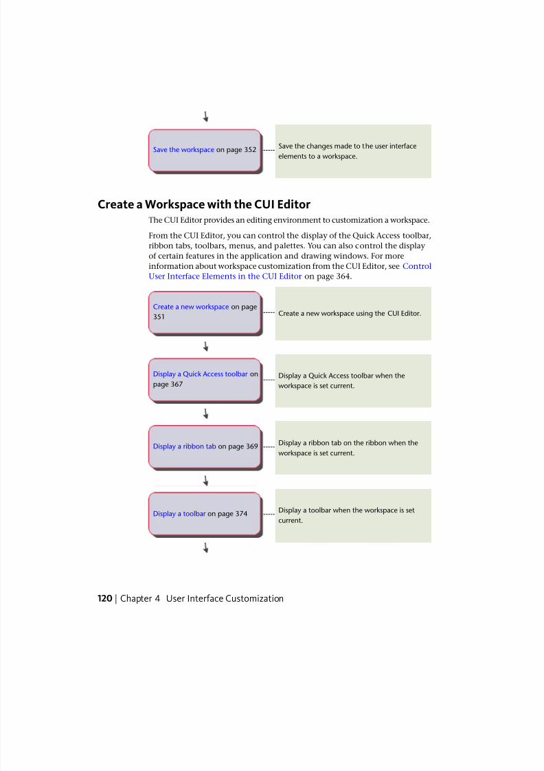
7/23/2019 Acad Customization
http://slidepdf.com/reader/full/acad-customization 128/553
Save the changes made to the user interface
elements to a workspace.-----Save the workspace on page 352
Create a Workspace with the CUI EditorThe CUI Editor provides an editing environment to customization a workspace.
From the CUI Editor, you can control the display of the Quick Access toolbar,
ribbon tabs, toolbars, menus, and palettes. You can also control the display
of certain features in the application and drawing windows. For more
information about workspace customization from the CUI Editor, see ControlUser Interface Elements in the CUI Editor on page 364.
Create a new workspace using the CUI Editor.-----Create a new workspace on page
351
Display a Quick Access toolbar when the
workspace is set current.-----
Display a Quick Access toolbar on
page 367
Display a ribbon tab on the ribbon when the
workspace is set current.-----Display a ribbon tab on page 369
Display a toolbar when the workspace is set
current.-----Display a toolbar on page 374
120 | Chapter 4 User Interface Customization
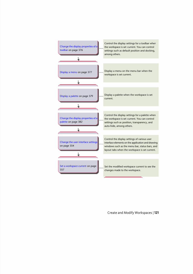
7/23/2019 Acad Customization
http://slidepdf.com/reader/full/acad-customization 129/553
Control the display settings for a toolbar when
the workspace is set current. You can control-----Change the display properties of a
toolbar on page 376 settings such as default position and docking,
among others.
Display a menu on the menu bar when the
workspace is set current.-----Display a menu on page 377
Display a palette when the workspace is setcurrent.
-----Display a palette on page 379
Control the display settings for a palette when
the workspace is set current. You can control-----Change the display properties of a
palette on page 382 settings such as position, transparency, and
auto-hide, among others.
Control the display settings of various user
interface elements on the application and drawing-----Change the user interface settings
on page 354 windows such as the menu bar, status bars, and
layout tabs when the workspace is set current.
Set the modified workspace current to see the
changes made to the workspace.-----
Set a workspace current on page
357
Create and Modify Workspaces | 121
7/23/2019 Acad Customization
http://slidepdf.com/reader/full/acad-customization 130/553
Create and Manage Customization FilesCustomization (CUIx) files are used to store commands, user interface elements,and references to partial CUIx files and AutoLISP files. CUIx files can be
designated as main, partial, or enterprise.
Basics of Customization FilesCustomization files are loaded into AutoCAD to define elements that make
up the user interface and are edited using the Customize User Interface (CUI)
Editor.
AutoCAD comes with several different CUIx files that can be tailored to your
work environment. AutoCAD has two main designations for CUIx files, main
and enterprise; by default AutoCAD uses a main CUIx file. You can customize
the files that come with AutoCAD or you can create your own CUIx files fromscratch using the Transfer tab in the Customize User Interface (CUI) Editor.
When customizing the CUIx files that come with AutoCAD or creating your
own CUIx files, the Customize User Interface (CUI) Editor creates a backup
copy of the file when you first start making changes to the CUIx file. This
allows you to restore the file if you delete something that you wanted to keep.
If you happen to modify a CUIx file that comes with AutoCAD, you can reset
it back to its original state.
The Customize User Interface allows you to not only create new user interface
elements and commands from scratch, but you can also copy existing user
interface elements and commands to modify them.
To set the working CUIx fileBefore you can add custom commands to a CUIx file, you must set a CUIx
file as the working file.
1 Click Manage tab ➤ Customization panel ➤ User Interface.
2 In the Customize User Interface Editor, Customize tab, Customizations
In <file name> pane, click the down arrow on the Customization Files
drop-down list.
3 Select Main Customization File <file name > or one of the loaded CUIx
files to set it as the working CUIx file.
122 | Chapter 4 User Interface Customization
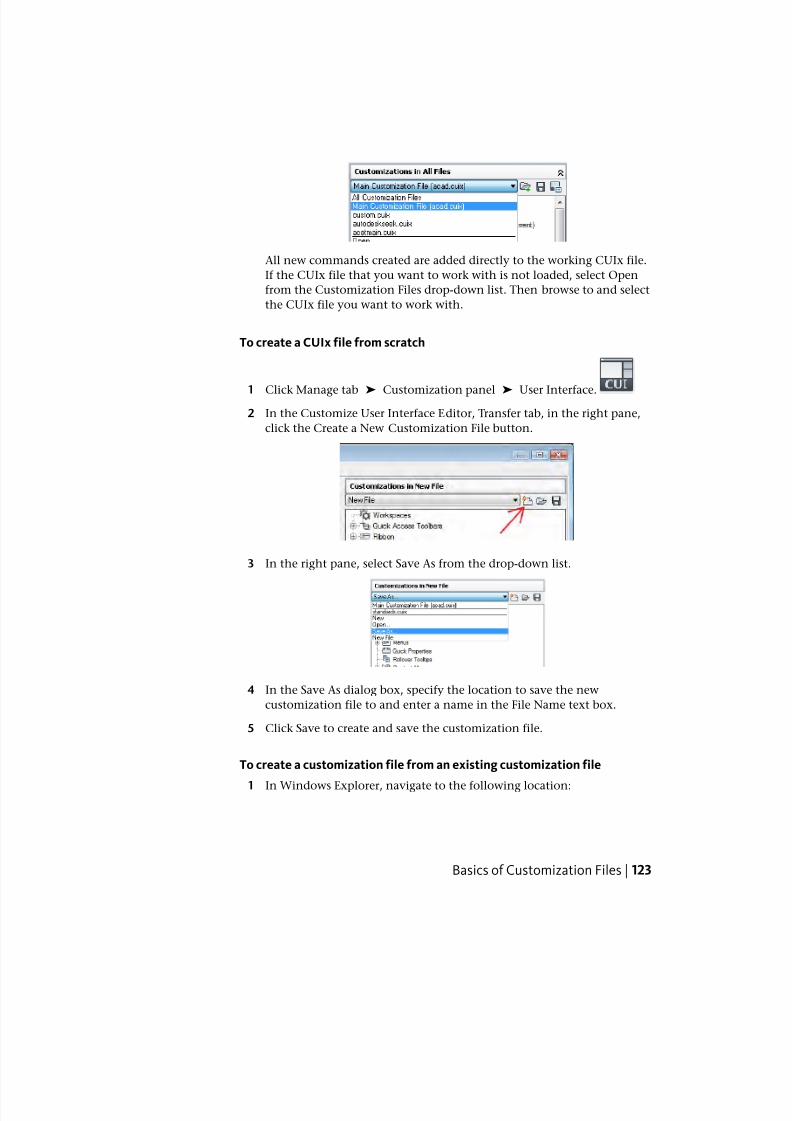
7/23/2019 Acad Customization
http://slidepdf.com/reader/full/acad-customization 131/553
All new commands created are added directly to the working CUIx file.
If the CUIx file that you want to work with is not loaded, select Open
from the Customization Files drop-down list. Then browse to and select
the CUIx file you want to work with.
To create a CUIx file from scratch
1 Click Manage tab ➤ Customization panel ➤ User Interface.
2 In the Customize User Interface Editor, Transfer tab, in the right pane,
click the Create a New Customization File button.
3 In the right pane, select Save As from the drop-down list.
4 In the Save As dialog box, specify the location to save the new
customization file to and enter a name in the File Name text box.
5 Click Save to create and save the customization file.
To create a customization file from an existing customization file
1 In Windows Explorer, navigate to the following location:
Basics of Customization Files | 123
7/23/2019 Acad Customization
http://slidepdf.com/reader/full/acad-customization 132/553
(Windows XP) <drive>:\Documents and Settings\<user profile
name>\Application Data\Autodesk\<product name>\<release
number>\<language>\support\<customization file name>.cuix
(Windows Vista) <drive>:\Users\<user profile
name>\AppData\Roaming\Autodesk\<product name>\<release
number>\<language>\support\<customization file name>.cuix
NOTE The folders under your profile may be hidden by default. To display
these files, you may need to change your display settings. Click Start menu
(Windows) ➤ Control Panel ➤ (Appearance and Themes, or Appearance
and Personalization) ➤ Folder Options. In the Folder Options dialog box,
View tab, click Show Hidden Files and Folders.
2 Copy the selected CUIx file to a new file name (such as enterprise.cuix ) or
location (such as the shared network location where users will access thefile) so that you preserve the original CUIx file (in case you want to modify
or use it again later).
WARNING This method of creating a new CUIx file can result in additional
work if you do not want all the commands and user interface elements in the
copied CUIx file.
To rename a customization group name
1 Click Manage tab ➤ Customization panel ➤ User Interface.
2 In the Customizations In <file name> pane, select a CUIx file from thedrop-down list.
3 In the Customizations In <file name> pane, right-click the customization
group name and click Rename.
124 | Chapter 4 User Interface Customization
7/23/2019 Acad Customization
http://slidepdf.com/reader/full/acad-customization 133/553
4 Enter a new customization group name and press Enter.
NOTE You can click, wait, and click again on the customization group name
to edit its name in-place.
NOTE The customization group name cannot contain spaces.
5 Click Apply.
To restore a customization backup file
1 Click Manage tab ➤ Customization panel ➤ User Interface.
2 In the Customize User Interface Editor, Customize tab, in the
Customizations In <file name> pane, right-click the customization group
name.
3 Click Restore <file name>.
4 Click Apply.
To reset a standard customization file
1 Click Manage tab ➤ Customization panel ➤ User Interface.
Basics of Customization Files | 125
7/23/2019 Acad Customization
http://slidepdf.com/reader/full/acad-customization 134/553
2 In the Customize User Interface Editor, Customize tab, in the
Customizations In <file name> pane, right-click over the customization
group name.
3 Click Reset <file name>.
NOTE Only CUIx files found in the UserDataCache folder under the install
location of AutoCAD can be reset.
4 Click Apply.
To designate a CUIx file as the main CUIx file
1 Click Application menu ➤ Options.
2 In the Options dialog box, Files tab, click the plus sign (+) next to
Customization Files to expand the list.
3 Click the plus sign (+) next to Main Customization File to expand it.
4 Select the item below Main Customization File and click Browse.
126 | Chapter 4 User Interface Customization
7/23/2019 Acad Customization
http://slidepdf.com/reader/full/acad-customization 135/553
5 In the Select a File dialog box, browse to and select the customization
file to load. Click Open.
The file you selected is now designated as the main customization file
for the program.
6 In the Options dialog box, click OK.
Quick Reference
Commands
CUI
Manages the customized user interface elements in the product.
MENU
Loads a customization file.
OPTIONS
Customizes the program settings.
System Variables
MENUNAME
Stores the customization file name, including the path for the file name.
Create and Load a Partial CUIx FileCreate, load, or unload partial customization files as you need them. Loading
and using a partial CUIx file allows you to create and modify most user
interface elements (toolbars, menus, ribbon panels, and so on) in a separate
CUIx file without having to import the customization to your main CUIx file.
The order of the partial CUIx files in the Partial Customization Files tree
determines the order they are loaded in the program. You can rearrange the
tree hierarchy to change the load order. Use the Transfer tab of the Customize
User Interface (CUI) Editor to create a partial CUIx file. For more information
Create and Load a Partial CUIx File | 127
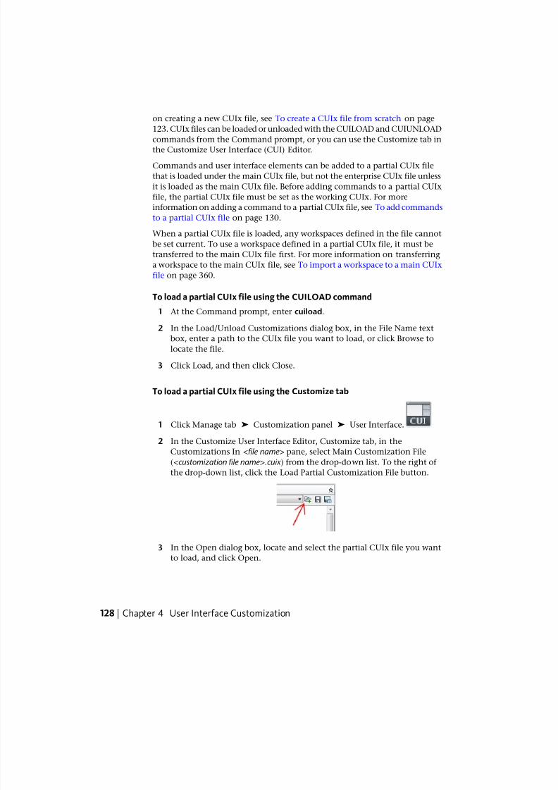
7/23/2019 Acad Customization
http://slidepdf.com/reader/full/acad-customization 136/553
on creating a new CUIx file, see To create a CUIx file from scratch on page
123. CUIx files can be loaded or unloaded with the CUILOAD and CUIUNLOAD
commands from the Command prompt, or you can use the Customize tab inthe Customize User Interface (CUI) Editor.
Commands and user interface elements can be added to a partial CUIx file
that is loaded under the main CUIx file, but not the enterprise CUIx file unless
it is loaded as the main CUIx file. Before adding commands to a partial CUIx
file, the partial CUIx file must be set as the working CUIx. For more
information on adding a command to a partial CUIx file, see To add commands
to a partial CUIx file on page 130.
When a partial CUIx file is loaded, any workspaces defined in the file cannot
be set current. To use a workspace defined in a partial CUIx file, it must be
transferred to the main CUIx file first. For more information on transferring
a workspace to the main CUIx file, see To import a workspace to a main CUIx
file on page 360.
To load a partial CUIx file using the CUILOAD command
1 At the Command prompt, enter cuiload.
2 In the Load/Unload Customizations dialog box, in the File Name text
box, enter a path to the CUIx file you want to load, or click Browse to
locate the file.
3 Click Load, and then click Close.
To load a partial CUIx file using the Customize tab
1 Click Manage tab ➤ Customization panel ➤ User Interface.
2 In the Customize User Interface Editor, Customize tab, in the
Customizations In <file name> pane, select Main Customization File
(<customization file name>.cuix ) from the drop-down list. To the right of
the drop-down list, click the Load Partial Customization File button.
3 In the Open dialog box, locate and select the partial CUIx file you want
to load, and click Open.
128 | Chapter 4 User Interface Customization
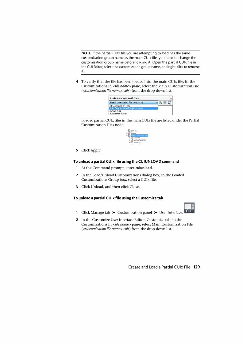
7/23/2019 Acad Customization
http://slidepdf.com/reader/full/acad-customization 137/553
NOTE If the partial CUIx file you are attempting to load has the same
customization group name as the main CUIx file, you need to change the
customization group name before loading it. Open the partial CUIx file in
the CUI Editor, select the customization group name, and right-click to rename
it.
4 To verify that the file has been loaded into the main CUIx file, in the
Customizations In <file name> pane, select the Main Customization File
(<customization file name>.cuix ) from the drop-down list.
Loaded partial CUIx files in the main CUIx file are listed under the PartialCustomization Files node.
5 Click Apply.
To unload a partial CUIx file using the CUIUNLOAD command
1 At the Command prompt, enter cuiunload.
2 In the Load/Unload Customizations dialog box, in the Loaded
Customizations Group box, select a CUIx file.
3 Click Unload, and then click Close.
To unload a partial CUIx file using the Customize tab
1 Click Manage tab ➤ Customization panel ➤ User Interface.
2 In the Customize User Interface Editor, Customize tab, in the
Customizations In <file name> pane, select Main Customization File
(<customization file name>.cuix ) from the drop-down list.
Create and Load a Partial CUIx File | 129
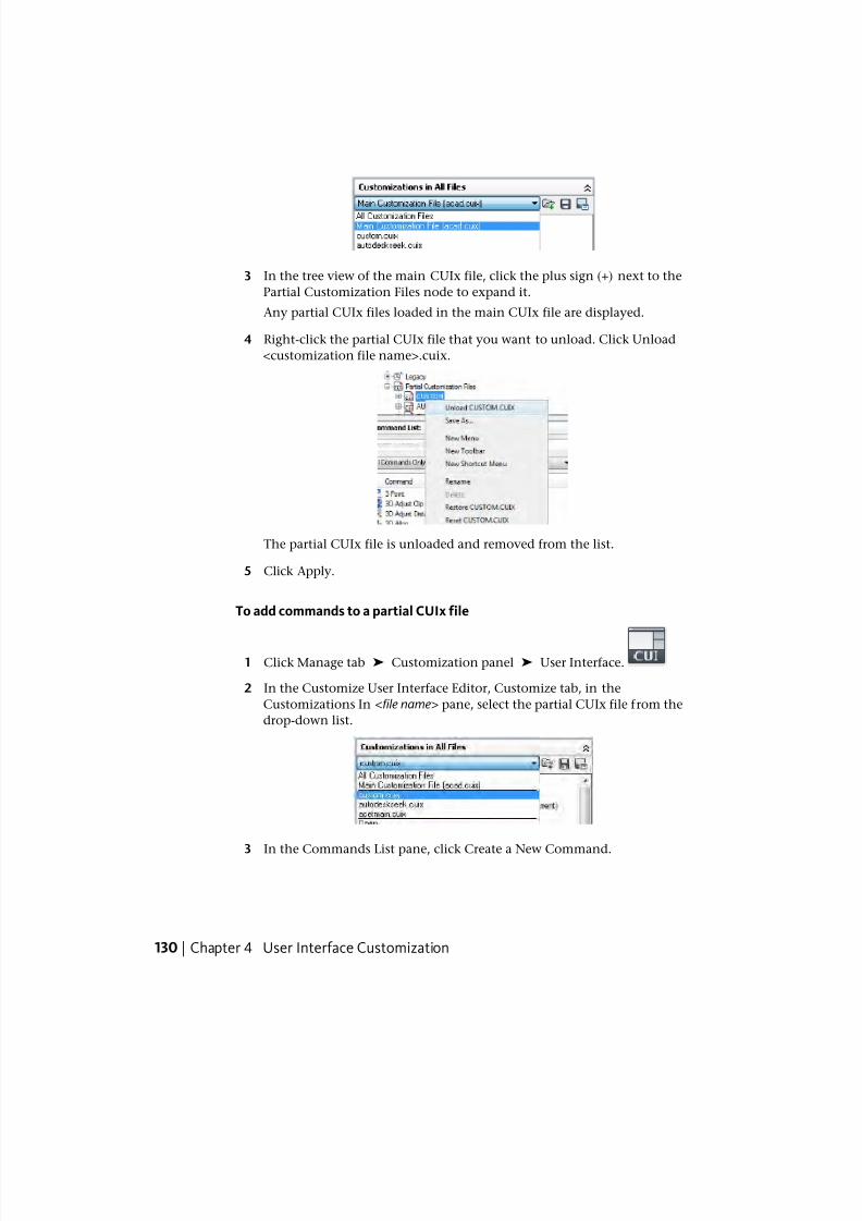
7/23/2019 Acad Customization
http://slidepdf.com/reader/full/acad-customization 138/553
3 In the tree view of the main CUIx file, click the plus sign (+) next to the
Partial Customization Files node to expand it.
Any partial CUIx files loaded in the main CUIx file are displayed.
4 Right-click the partial CUIx file that you want to unload. Click Unload
<customization file name>.cuix.
The partial CUIx file is unloaded and removed from the list.
5 Click Apply.
To add commands to a partial CUIx file
1 Click Manage tab ➤ Customization panel ➤ User Interface.
2 In the Customize User Interface Editor, Customize tab, in the
Customizations In <file name> pane, select the partial CUIx file from the
drop-down list.
3 In the Commands List pane, click Create a New Command.
130 | Chapter 4 User Interface Customization
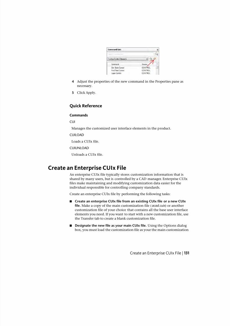
7/23/2019 Acad Customization
http://slidepdf.com/reader/full/acad-customization 139/553
4 Adjust the properties of the new command in the Properties pane as
necessary.
5 Click Apply.
Quick Reference
Commands
CUI
Manages the customized user interface elements in the product.
CUILOAD
Loads a CUIx file.
CUIUNLOAD
Unloads a CUIx file.
Create an Enterprise CUIx FileAn enterprise CUIx file typically stores customization information that is
shared by many users, but is controlled by a CAD manager. Enterprise CUIx
files make maintaining and modifying customization data easier for the
individual responsible for controlling company standards.
Create an enterprise CUIx file by performing the following tasks:
■ Create an enterprise CUIx file from an existing CUIx file or a new CUIx
file. Make a copy of the main customization file (acad.cuix ) or another
customization file of your choice that contains all the base user interface
elements you need. If you want to start with a new customization file, use
the Transfer tab to create a blank customization file.
■ Designate the new file as your main CUIx file. Using the Options dialog
box, you must load the customization file as your the main customization
Create an Enterprise CUIx File | 131
7/23/2019 Acad Customization
http://slidepdf.com/reader/full/acad-customization 140/553
file so you make edits to all of the different user interface elements. Make
sure to note which customization file is currently designated as the main
customization file, as you will need to restore it later.
■ Modify the contents of the enterprise CUIx file. Once the customization
file is designated as the main customization file, you can change the
customization group name and modify the CUIx file contents as needed.
Changing the customization group name allows you to load more than
one CUIx file in the program at one time. CUIx files with the same
customization group name cannot be loaded into the program.
■ Replace the main CUIx file. Using the Options dialog box, replace the
previous customization file that was designated as the main customization
file.
■ Save the enterprise CUIx file to a shared network location. When you save
the new enterprise file to a shared network location, all of your users thathave access to the specified location can access the file.
NOTE The folder where you place the enterprise CUIx file should be in a shared
location that your users can access. To learn more about creating a network
share, see “How to Create a Network Share” in the Network Administrator's
Guide .
■ Specify the enterprise CUIx file location. The program automatically
designates an enterprise customization file as read-only when you specify
its file location in the Options dialog box. Specifying the enterprise
customization file location can be done on individual workstations or in
the Deployment wizard. For more information about setting the location
in the Deployment wizard, see “Select Search Paths and File Locations” inthe Network Administrator's Guide .
WARNING Even though the Customize User Interface (CUI) Editor loads the
enterprise customization file as read-only, this still doesn’t completely protect
the file from being modified. The enterprise customization file could be loaded
as the main customization file and then modified. To protect the enterprise
customization file, the location where it is stored be marked as read-only and
write access should be limited to those you want to be able to edit the file.
To designate a CUIx file as an enterprise CUIx file
1 On each user's workstation in AutoCAD, click Application menu ➤ Options.
132 | Chapter 4 User Interface Customization
7/23/2019 Acad Customization
http://slidepdf.com/reader/full/acad-customization 141/553
2 In the Options dialog box, Files tab, click the plus sign (+) next to
Customization Files to expand the list.
3 Click the plus sign next to Enterprise Customization File to open it.
4 Select the item below Enterprise Customization Files and click Browse.
5 In the Select a File dialog box, browse to the location of the enterprise
customization file. Click Open.
The enterprise CUIx file if shared, must be saved in a location that all
users can access.
6 In the Options dialog box, click OK.
NOTE In the Deployment wizard, you designate the enterprise CUIx file in
the wizard's Specify Settings page. For more information about designating
an enterprise CUIx file in the Deployment wizard, see “Select Search Paths
and File Locations” in the Network Administrator's Guide .
To modify an enterprise CUIx file
1 Click Application menu ➤ Options.
2 In the Options dialog box, Files tab, click the plus sign (+) next to
Customization Files to expand the list.
Create an Enterprise CUIx File | 133
7/23/2019 Acad Customization
http://slidepdf.com/reader/full/acad-customization 142/553
3 Click the plus sign next to Main Customization File to expand it.
Take note of the current main CUIx file’s name and location as you will
need to restore it later.
4 Select the item below Main Customization Files and click Browse. In the
Select a File dialog box, browse to the location of the enterprise
customization file. Click Open.
5 Click the plus sign next to Enterprise Customization File to expand it.
Take note of the current enterprise CUIx file’s name and location as you
will need to restore it later.
6 Select the item below Enterprise Customization Files and click Browse.
In the Select a File dialog box, browse to the location of the main
customization file. Click Open.
7 In the Options dialog box, click OK to save the changes.
8 Click Manage tab ➤ Customization panel ➤ User Interface.
9 In the Customize User Interface Editor, Customize tab, create new
commands and user interface elements as necessary.
10 Once done adding new commands and user interface elements, click OK.
Switch the file names of the main and enterprise values around in the
Options dialog box.
The main and enterprise CUIx files should now resemble the original
configuration prior to making the changes.
TIP You can create two different profiles that can be used to switch between your
main and enterprise CUIx files. One profile will have the CUIx files in a normal
configuration that is used by your drafters, and the other profile has the main and
enterprise CUIx files switched around making the enterprise customization file
editable.
Quick Reference
Commands
CUI
Manages the customized user interface elements in the product.
134 | Chapter 4 User Interface Customization
7/23/2019 Acad Customization
http://slidepdf.com/reader/full/acad-customization 143/553
CUIEXPORT
Exports customized settings from the main CUIx file to an enterprise orpartial CUIx file.
CUILOAD
Loads a CUIx file.
CUIUNLOAD
Unloads a CUIx file.
MENU
Loads a customization file.
OPTIONS
Customizes the program settings.
System Variables
ENTERPRISEMENU
Stores the enterprise customization file name (if defined), including the path
for the file name.
MENUNAME
Stores the customization file name, including the path for the file name.
Find and Replace Commands and Text in a CUIx FileYou can search one or more CUIx files for commands or search strings(including commands or user interface element names, command display
names, descriptions, macros, and tags). You can also replace commands or
search strings one at a time or all at once.
You can limit or expand your search depending on the search results you want
to achieve.
■ Limit the search to commands located in the Command List pane. This
search does not include the names of user interface elements, the
commands that are associated to them, and their properties. For example,
if you limit the search for the LINE command in the Command List only,
a message similar to the following is displayed when you start your search:
“Search string found in command 'Dimension, Linear' property 'Name' at
position 11 (1/12).”
Find and Replace Commands and Text in a CUIx File | 135
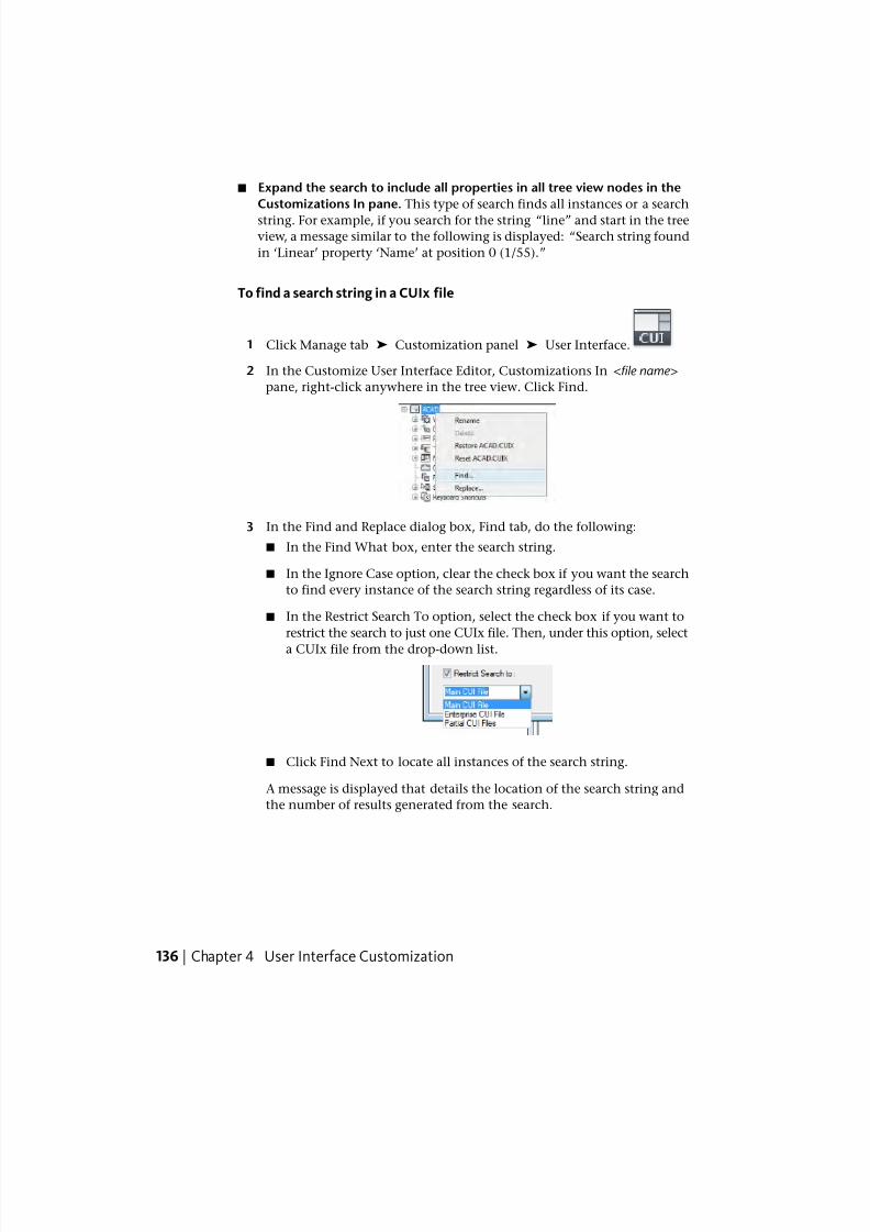
7/23/2019 Acad Customization
http://slidepdf.com/reader/full/acad-customization 144/553
■ Expand the search to include all properties in all tree view nodes in the
Customizations In pane. This type of search finds all instances or a search
string. For example, if you search for the string “line” and start in the treeview, a message similar to the following is displayed: “Search string found
in ‘Linear’ property ‘Name’ at position 0 (1/55).”
To find a search string in a CUIx file
1 Click Manage tab ➤ Customization panel ➤ User Interface.
2 In the Customize User Interface Editor, Customizations In <file name>pane, right-click anywhere in the tree view. Click Find.
3 In the Find and Replace dialog box, Find tab, do the following:
■ In the Find What box, enter the search string.
■ In the Ignore Case option, clear the check box if you want the search
to find every instance of the search string regardless of its case.
■ In the Restrict Search To option, select the check box if you want to
restrict the search to just one CUIx file. Then, under this option, select
a CUIx file from the drop-down list.
■ Click Find Next to locate all instances of the search string.
A message is displayed that details the location of the search string and
the number of results generated from the search.
136 | Chapter 4 User Interface Customization
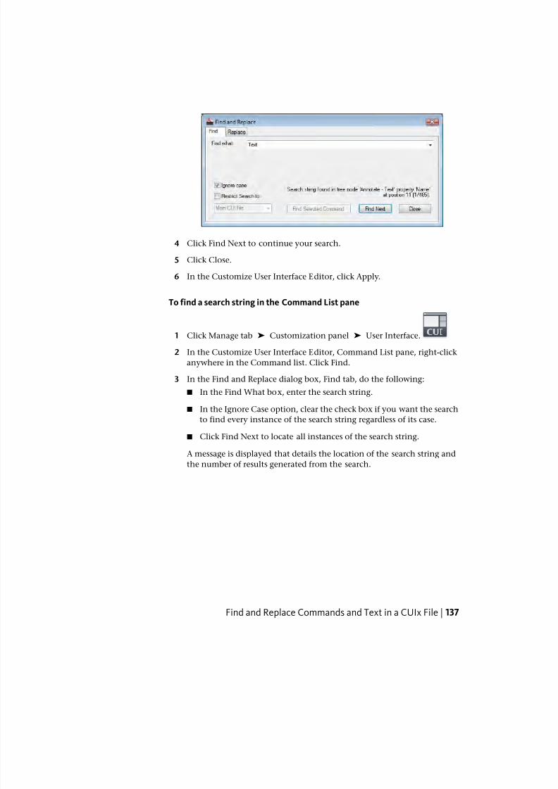
7/23/2019 Acad Customization
http://slidepdf.com/reader/full/acad-customization 145/553
4 Click Find Next to continue your search.
5 Click Close.
6 In the Customize User Interface Editor, click Apply.
To find a search string in the Command List pane
1 Click Manage tab ➤ Customization panel ➤ User Interface.
2 In the Customize User Interface Editor, Command List pane, right-click
anywhere in the Command list. Click Find.
3 In the Find and Replace dialog box, Find tab, do the following:
■ In the Find What box, enter the search string.
■ In the Ignore Case option, clear the check box if you want the search
to find every instance of the search string regardless of its case.
■ Click Find Next to locate all instances of the search string.
A message is displayed that details the location of the search string and
the number of results generated from the search.
Find and Replace Commands and Text in a CUIx File | 137
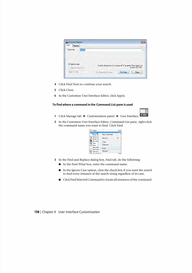
7/23/2019 Acad Customization
http://slidepdf.com/reader/full/acad-customization 146/553
4 Click Find Next to continue your search.
5 Click Close.
6 In the Customize User Interface Editor, click Apply.
To find where a command in the Command List pane is used
1 Click Manage tab ➤ Customization panel ➤ User Interface.
2 In the Customize User Interface Editor, Command List pane, right-click
the command name you want to find. Click Find.
3 In the Find and Replace dialog box, Find tab, do the following:
■ In the Find What box, enter the command name.
■ In the Ignore Case option, clear the check box if you want the search
to find every instance of the search string regardless of its case.
■ Click Find Selected Command to locate all instances of the command.
138 | Chapter 4 User Interface Customization
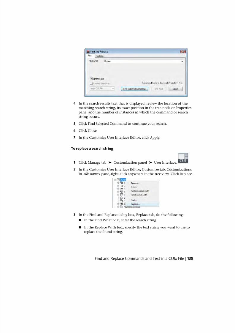
7/23/2019 Acad Customization
http://slidepdf.com/reader/full/acad-customization 147/553
4 In the search results text that is displayed, review the location of the
matching search string, its exact position in the tree node or Properties
pane, and the number of instances in which the command or search
string occurs.
5 Click Find Selected Command to continue your search.
6 Click Close.
7 In the Customize User Interface Editor, click Apply.
To replace a search string
1 Click Manage tab ➤ Customization panel ➤ User Interface.
2 In the Customize User Interface Editor, Customize tab, Customizations
In <file name> pane, right-click anywhere in the tree view. Click Replace.
3 In the Find and Replace dialog box, Replace tab, do the following:
■ In the Find What box, enter the search string.
■ In the Replace With box, specify the text string you want to use to
replace the found string.
Find and Replace Commands and Text in a CUIx File | 139
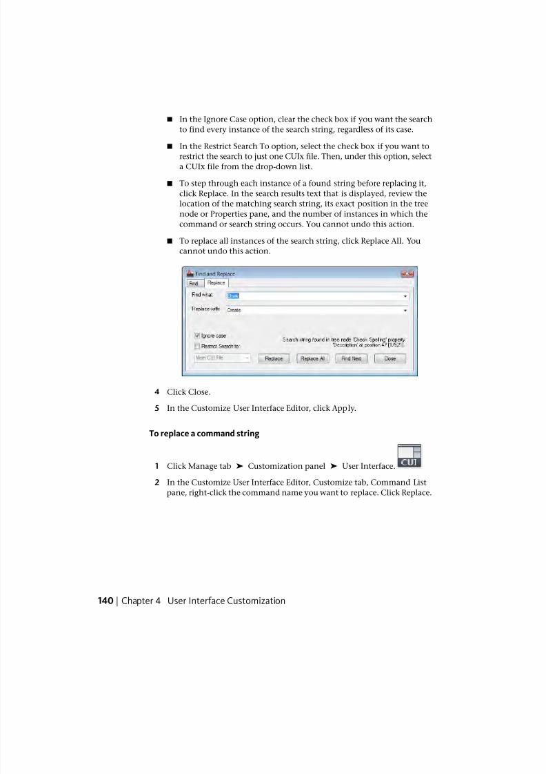
7/23/2019 Acad Customization
http://slidepdf.com/reader/full/acad-customization 148/553
■ In the Ignore Case option, clear the check box if you want the search
to find every instance of the search string, regardless of its case.
■ In the Restrict Search To option, select the check box if you want to
restrict the search to just one CUIx file. Then, under this option, select
a CUIx file from the drop-down list.
■ To step through each instance of a found string before replacing it,
click Replace. In the search results text that is displayed, review the
location of the matching search string, its exact position in the tree
node or Properties pane, and the number of instances in which the
command or search string occurs. You cannot undo this action.
■ To replace all instances of the search string, click Replace All. You
cannot undo this action.
4 Click Close.
5 In the Customize User Interface Editor, click Apply.
To replace a command string
1 Click Manage tab ➤ Customization panel ➤ User Interface.
2 In the Customize User Interface Editor, Customize tab, Command List
pane, right-click the command name you want to replace. Click Replace.
140 | Chapter 4 User Interface Customization
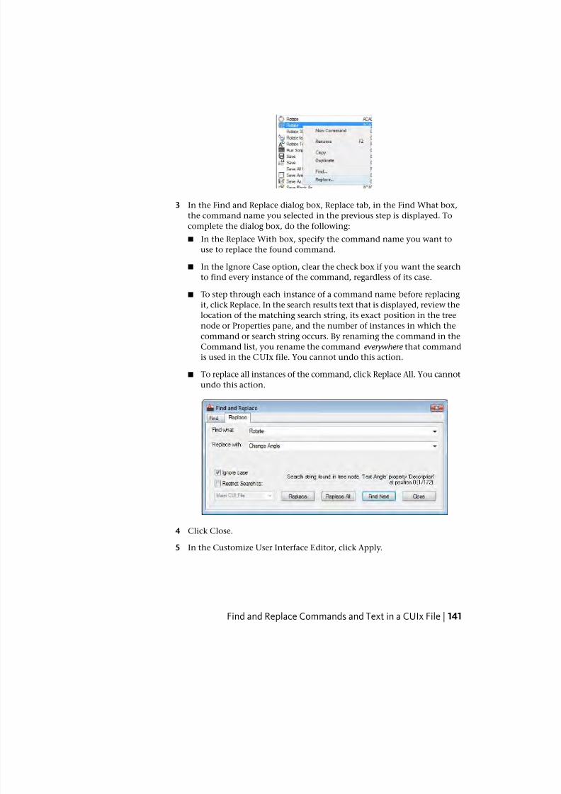
7/23/2019 Acad Customization
http://slidepdf.com/reader/full/acad-customization 149/553
3 In the Find and Replace dialog box, Replace tab, in the Find What box,
the command name you selected in the previous step is displayed. To
complete the dialog box, do the following:
■ In the Replace With box, specify the command name you want to
use to replace the found command.
■ In the Ignore Case option, clear the check box if you want the search
to find every instance of the command, regardless of its case.
■ To step through each instance of a command name before replacing
it, click Replace. In the search results text that is displayed, review the
location of the matching search string, its exact position in the tree
node or Properties pane, and the number of instances in which the
command or search string occurs. By renaming the command in the
Command list, you rename the command everywhere that command
is used in the CUIx file. You cannot undo this action.
■ To replace all instances of the command, click Replace All. You cannot
undo this action.
4 Click Close.
5 In the Customize User Interface Editor, click Apply.
Find and Replace Commands and Text in a CUIx File | 141
7/23/2019 Acad Customization
http://slidepdf.com/reader/full/acad-customization 150/553
Quick Reference
Commands
CUI
Manages the customized user interface elements in the product.
Customize CommandsCommands in the Customize User Interface (CUI) Editor are used to define
custom macros which are used to start standard and custom commands which
can be executed from the command prompt in AutoCAD.
Overview of CommandsYou can easily create, edit, and reuse commands. The Customize tab of the
Customize User Interface (CUI) Editor allows you to add any command listed
in the Command List pane to a toolbar, menu, and one of the other user
interface element that can be customized.
When you change the properties of a command in the Command List pane
or the tree view in the Customizations In pane, the properties of the command
are changed everywhere the command is referenced. Each property of a
command in the Command List pane controls which actions are taken when
the command is used and how the command looks when added to a user
interface element.
The following table shows the properties of the Scale command as they appear
in the Properties pane.
Properties for the Scale command in the Command List pane
ExampleDescriptionPropertiespane item
ScaleString displayed as a menu name or as a tooltip
when you click a toolbar button. The string
Name
must include alphanumeric characters with no
punctuation other than a hyphen (-) or an un-
derscore (_).
Enlarges or reduces
selected objects, keep-
String displayed as a tooltip when the cursor
hovers over a toolbar or panel button, or menuitem.
Descrip-
tioning the proportions of
142 | Chapter 4 User Interface Customization
7/23/2019 Acad Customization
http://slidepdf.com/reader/full/acad-customization 151/553
Properties for the Scale command in the Command List pane
ExampleDescriptionPropertiespane item
the object the same
after scaling
Displays the file name and ID for the extended
tooltip that is displayed when the cursor hovers
over a toolbar or panel button.
Extended
Help File
SCALEString that contains the name of the command
that is related to the command.
Command
Display
Name
$M=$(if,$(eq,$(sub-str,$(getvar,cmd-
names),
The command macro. It follows the standardmacro syntax.
NOTE When you change the name of a macro,
the name of its corresponding menu item or
toolbar button does not change. You must
change a menu item or toolbar button name
by selecting it in the tree view.
Macro
1,4),GRIP),_scale, C C_scale)
Keywords associated to a command. Tags
provide an additional field to search for a loaded
Tags
command when using the Search field in the
application menu.
ID_ScaleTag that uniquely identifies a command.Element ID
RCDATA_16_SCALEID string of the small-image resource (16 × 16
bitmap). The string must include alphanumeric
Small Im-
age
characters with no punctuation other than a
hyphen (-) or an underscore (_). It can also be
a user-defined bitmap. Click the [ ] button to
open the Select Image File dialog box.
RCDATA_32_SCALEID string of the large-image resource (32 × 32
bitmap). If the specified bitmap is not 32 × 32,
Large Im-
age
the program scales it to that size. The string
must include alphanumeric characters with no
punctuation other than a hyphen (-) or an un-
Overview of Commands | 143
7/23/2019 Acad Customization
http://slidepdf.com/reader/full/acad-customization 152/553
Properties for the Scale command in the Command List pane
ExampleDescriptionPropertiespane item
derscore (_). It can also be a user-defined bit-
map. Click the [ ] button to open the Select
Image File dialog box
Quick Reference
Commands
CUI
Manages the customized user interface elements in the product.
Create, Edit, and Reuse CommandsYou can create a new command from scratch, copy an existing command to
create a new command, or edit the properties of an existing command. When
you create or edit a command, the properties you can define are the command
name, description, extended help file, command display name, macro, tags,
element ID (for new commands only), and small or large image.
When you change the properties of a command in the Command List pane,
the command is updated for all user interface elements that reference the
command.
To create a command
1 Click Manage tab ➤ Customization panel ➤ User Interface.
2 In the Customize User Interface Editor, Customize tab, Command List
pane, click Create a New Command.
144 | Chapter 4 User Interface Customization
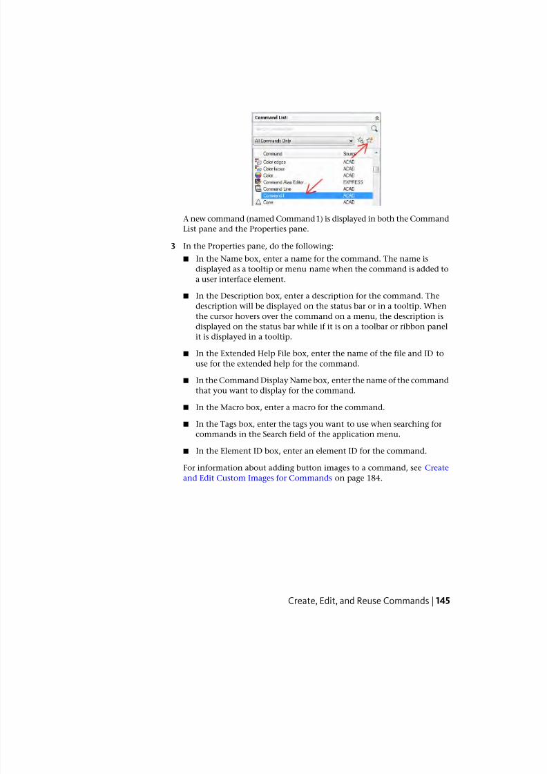
7/23/2019 Acad Customization
http://slidepdf.com/reader/full/acad-customization 153/553
A new command (named Command1) is displayed in both the Command
List pane and the Properties pane.
3 In the Properties pane, do the following:
■ In the Name box, enter a name for the command. The name is
displayed as a tooltip or menu name when the command is added toa user interface element.
■ In the Description box, enter a description for the command. The
description will be displayed on the status bar or in a tooltip. When
the cursor hovers over the command on a menu, the description is
displayed on the status bar while if it is on a toolbar or ribbon panel
it is displayed in a tooltip.
■ In the Extended Help File box, enter the name of the file and ID to
use for the extended help for the command.
■ In the Command Display Name box, enter the name of the command
that you want to display for the command.
■ In the Macro box, enter a macro for the command.
■ In the Tags box, enter the tags you want to use when searching for
commands in the Search field of the application menu.
■ In the Element ID box, enter an element ID for the command.
For information about adding button images to a command, see Create
and Edit Custom Images for Commands on page 184.
Create, Edit, and Reuse Commands | 145
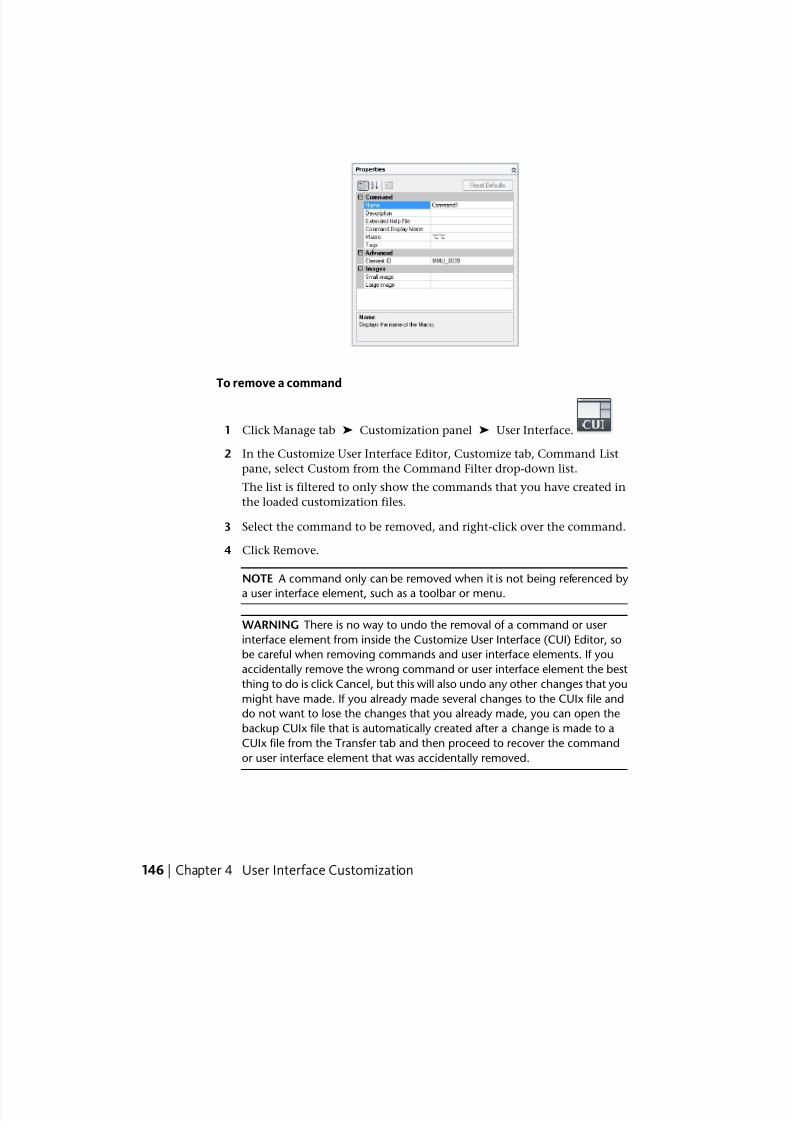
7/23/2019 Acad Customization
http://slidepdf.com/reader/full/acad-customization 154/553
To remove a command
1 Click Manage tab ➤ Customization panel ➤ User Interface.
2 In the Customize User Interface Editor, Customize tab, Command List
pane, select Custom from the Command Filter drop-down list.
The list is filtered to only show the commands that you have created in
the loaded customization files.
3 Select the command to be removed, and right-click over the command.
4 Click Remove.
NOTE A command only can be removed when it is not being referenced by
a user interface element, such as a toolbar or menu.
WARNING There is no way to undo the removal of a command or user
interface element from inside the Customize User Interface (CUI) Editor, so
be careful when removing commands and user interface elements. If you
accidentally remove the wrong command or user interface element the best
thing to do is click Cancel, but this will also undo any other changes that you
might have made. If you already made several changes to the CUIx file and
do not want to lose the changes that you already made, you can open the
backup CUIx file that is automatically created after a change is made to a
CUIx file from the Transfer tab and then proceed to recover the command
or user interface element that was accidentally removed.
146 | Chapter 4 User Interface Customization
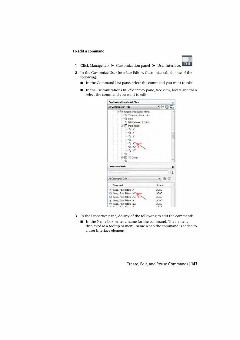
7/23/2019 Acad Customization
http://slidepdf.com/reader/full/acad-customization 155/553
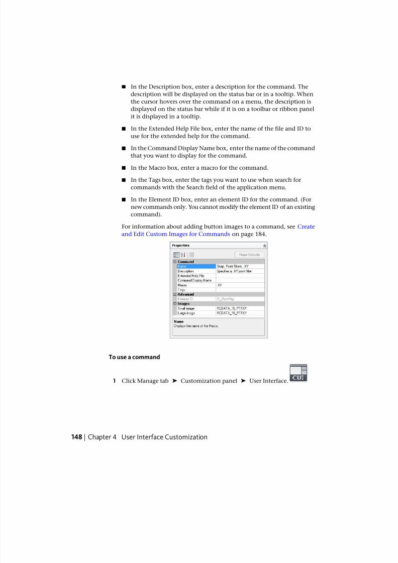
7/23/2019 Acad Customization
http://slidepdf.com/reader/full/acad-customization 156/553
■ In the Description box, enter a description for the command. The
description will be displayed on the status bar or in a tooltip. When
the cursor hovers over the command on a menu, the description is
displayed on the status bar while if it is on a toolbar or ribbon panel
it is displayed in a tooltip.
■ In the Extended Help File box, enter the name of the file and ID to
use for the extended help for the command.
■ In the Command Display Name box, enter the name of the command
that you want to display for the command.
■ In the Macro box, enter a macro for the command.
■ In the Tags box, enter the tags you want to use when search for
commands with the Search field of the application menu.
■ In the Element ID box, enter an element ID for the command. (For
new commands only. You cannot modify the element ID of an existing
command).
For information about adding button images to a command, see Create
and Edit Custom Images for Commands on page 184.
To use a command
1 Click Manage tab ➤ Customization panel ➤ User Interface.
148 | Chapter 4 User Interface Customization
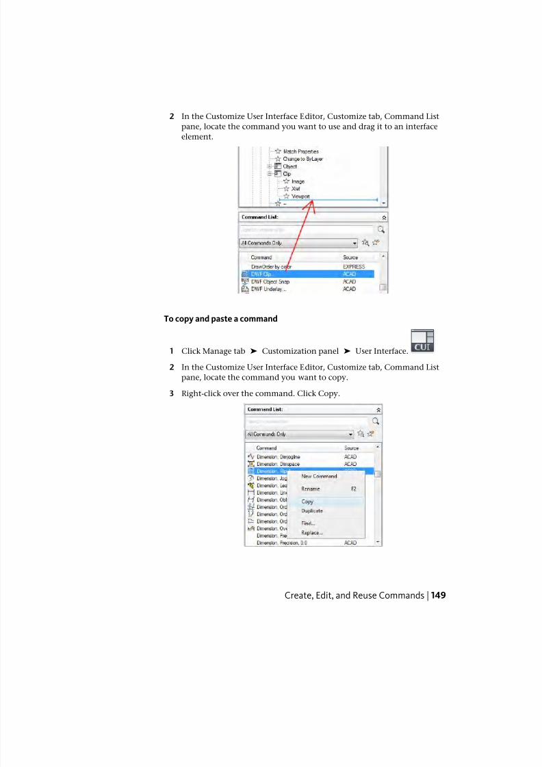
7/23/2019 Acad Customization
http://slidepdf.com/reader/full/acad-customization 157/553
2 In the Customize User Interface Editor, Customize tab, Command List
pane, locate the command you want to use and drag it to an interface
element.
To copy and paste a command
1 Click Manage tab ➤ Customization panel ➤ User Interface.
2 In the Customize User Interface Editor, Customize tab, Command List
pane, locate the command you want to copy.
3 Right-click over the command. Click Copy.
Create, Edit, and Reuse Commands | 149
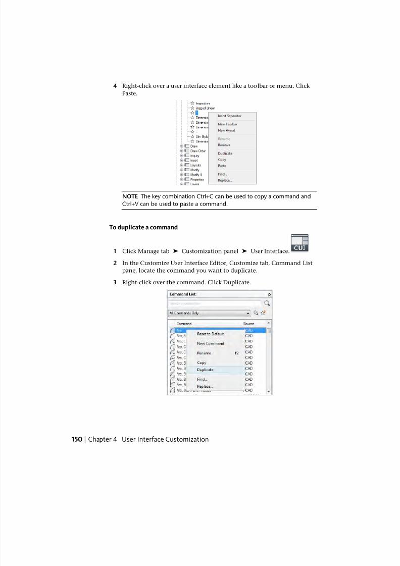
7/23/2019 Acad Customization
http://slidepdf.com/reader/full/acad-customization 158/553
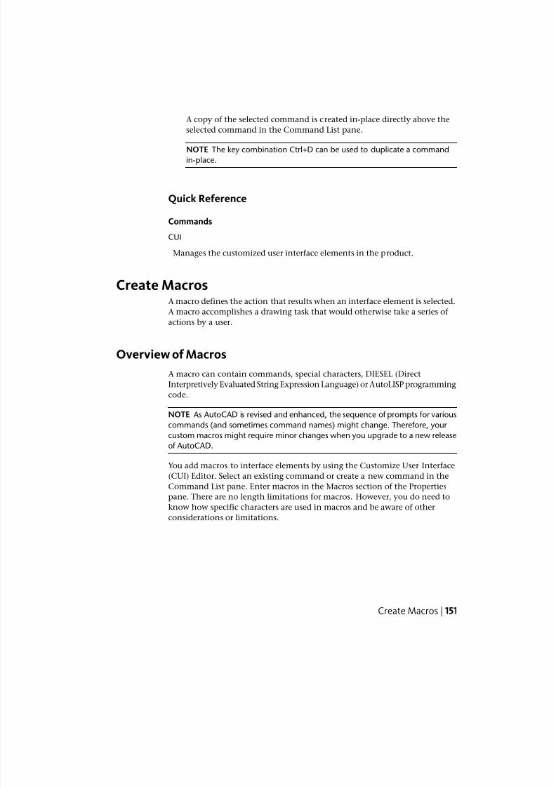
7/23/2019 Acad Customization
http://slidepdf.com/reader/full/acad-customization 159/553
A copy of the selected command is created in-place directly above the
selected command in the Command List pane.
NOTE The key combination Ctrl+D can be used to duplicate a command
in-place.
Quick Reference
Commands
CUI
Manages the customized user interface elements in the product.
Create MacrosA macro defines the action that results when an interface element is selected.
A macro accomplishes a drawing task that would otherwise take a series of
actions by a user.
Overview of Macros
A macro can contain commands, special characters, DIESEL (Direct
Interpretively Evaluated String Expression Language) or AutoLISP programming
code.
NOTE As AutoCAD is revised and enhanced, the sequence of prompts for variouscommands (and sometimes command names) might change. Therefore, your
custom macros might require minor changes when you upgrade to a new release
of AutoCAD.
You add macros to interface elements by using the Customize User Interface
(CUI) Editor. Select an existing command or create a new command in the
Command List pane. Enter macros in the Macros section of the Properties
pane. There are no length limitations for macros. However, you do need to
know how specific characters are used in macros and be aware of other
considerations or limitations.
Create Macros | 151
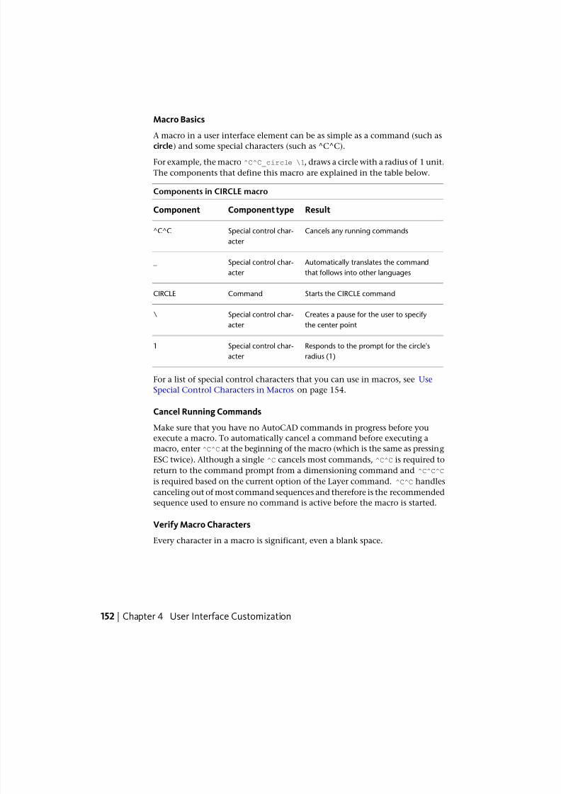
7/23/2019 Acad Customization
http://slidepdf.com/reader/full/acad-customization 160/553
Macro Basics
A macro in a user interface element can be as simple as a command (such ascircle) and some special characters (such as ^C^C).
For example, the macro ^C^C_circle \1, draws a circle with a radius of 1 unit.
The components that define this macro are explained in the table below.
Components in CIRCLE macro
ResultComponent typeComponent
Cancels any running commandsSpecial control char-
acter
^C^C
Automatically translates the command
that follows into other languages
Special control char-
acter
_
Starts the CIRCLE commandCommandCIRCLE
Creates a pause for the user to specify
the center point
Special control char-
acter
\
Responds to the prompt for the circle's
radius (1)
Special control char-
acter
1
For a list of special control characters that you can use in macros, see Use
Special Control Characters in Macros on page 154.
Cancel Running Commands
Make sure that you have no AutoCAD commands in progress before you
execute a macro. To automatically cancel a command before executing a
macro, enter ^C^C at the beginning of the macro (which is the same as pressing
ESC twice). Although a single ^C cancels most commands, ^C^C is required to
return to the command prompt from a dimensioning command and ^C^C^C
is required based on the current option of the Layer command. ^C^C handles
canceling out of most command sequences and therefore is the recommended
sequence used to ensure no command is active before the macro is started.
Verify Macro Characters
Every character in a macro is significant, even a blank space.
152 | Chapter 4 User Interface Customization
7/23/2019 Acad Customization
http://slidepdf.com/reader/full/acad-customization 161/553
When you place a space at the end of the macro, AutoCAD processes the
macro as though you had entered a command (circle, for example) and then
pressed the SPACEBAR to complete the command.
Terminate Macros
Some macros require special terminators. Some commands (TEXT, for example)
require you to press ENTER rather than SPACEBAR to terminate the command.
Some commands require more than one space (or ENTER) to complete, but
some text editors cannot create a line with trailing blanks.
Two special conventions resolve these problems.
■ A semicolon (;) in a macro automatically issues ENTER at the command
prompt.
■ If a line ends with a control character, a backslash (\), a plus sign (+), or a
semicolon (;), AutoCAD does not add a blank space after it.
An item that ends with a backslash (\) pauses a macro for user input.
Compare the following macros:
ucs
ucs ;
The first example enters ucs at the command prompt and presses SPACEBAR.
The following prompt is displayed.
Specify origin of UCS or
[Face/NAmed/OBject/Previous/View/World/X/Y/Z/ZAxis] <World>:
The second example enters ucs, presses SPACEBAR, and presses ENTER, whichaccepts the default value (World).
Suppress Echoes and Prompts in Macros
Characters in a macro appear in the command window as though you had
typed the characters on the keyboard. They are also displayed in the user
interface element. This display duplication is called “echoing”. You can
suppress the “echoed” displays with the MENUECHO system variable. If echoes
and prompts from item input are turned off, a ^P in the item turns them off.
Create Long Macros
You can create a macro of any length, without requiring any special characters
at the end of a line. The Properties pane in the Customize User Interface (CUI)Editor accepts a macro of any length.
Create Macros | 153
7/23/2019 Acad Customization
http://slidepdf.com/reader/full/acad-customization 162/553
To assign or modify a command macro
1 Click Manage tab ➤ Customization panel ➤ User Interface.
2 In the Customize User Interface Editor, Customize tab, Command List
pane, locate the command you want to assign (or modify) a command
macro.
3 In the Properties pane, select the Macro field and click the [ ] button that
is displayed.
The Long String Editor dialog box is displayed.
4 In the Long String Editor, edit the macro as desired and click OK.
You are returned to the Customize User Interface Editor.
Quick Reference
Commands
CUI
Manages the customized user interface elements in the product.
Use Special Control Characters in MacrosYou can use special characters, including control characters, in macros. In a
macro, the caret (^) is equivalent to pressing the Ctrl key on the keyboard.
You can combine the caret with another character to construct macros thatdo such things as turn the grid on and off (^G) or cancel a command (^C).
The macro for the Address command below uses the backslash (\) to pause
for user input and the semicolon (;) for ENTER.
text \.4 0 DRAFT Inc;;;Main St.;;;City, State;
The macro starts the TEXT command, pauses for the user to specify a start
point, and then enters the address on three lines. In the triple semicolon (;;;),
the first semicolon ends the text string, the second repeats TEXT, and the
third accepts the default placement below the previous line.
154 | Chapter 4 User Interface Customization
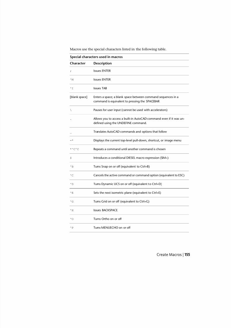
7/23/2019 Acad Customization
http://slidepdf.com/reader/full/acad-customization 163/553
Macros use the special characters listed in the following table.
Special characters used in macros
DescriptionCharacter
Issues ENTER;
Issues ENTER^M
Issues TAB^I
Enters a space; a blank space between command sequences in a
command is equivalent to pressing the SPACEBAR
[blank space]
Pauses for user input (cannot be used with accelerators)\
Allows you to access a built-in AutoCAD command even if it was un-
defined using the UNDEFINE command.
.
Translates AutoCAD commands and options that follow_
Displays the current top-level pull-down, shortcut, or image menu=*
Repeats a command until another command is chosen*^C^C
Introduces a conditional DIESEL macro expression ($M=)$
Turns Snap on or off (equivalent to Ctrl+B)^B
Cancels the active command or command option (equivalent to ESC)^C
Turns Dynamic UCS on or off (equivalent to Ctrl+D)^D
Sets the next isometric plane (equivalent to Ctrl+E)^E
Turns Grid on or off (equivalent to Ctrl+G)^G
Issues BACKSPACE^H
Turns Ortho on or off ^O
Turns MENUECHO on or off ^P
Create Macros | 155
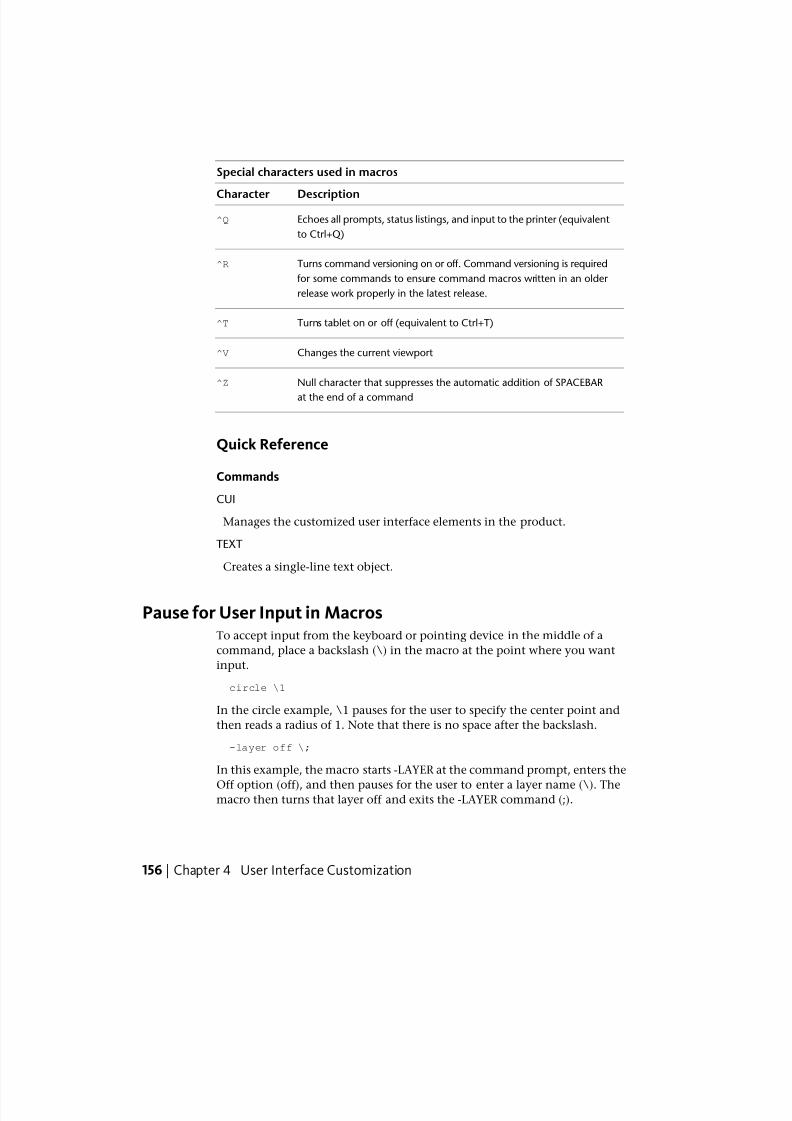
7/23/2019 Acad Customization
http://slidepdf.com/reader/full/acad-customization 164/553
Special characters used in macros
DescriptionCharacter
Echoes all prompts, status listings, and input to the printer (equivalent
to Ctrl+Q)
^Q
Turns command versioning on or off. Command versioning is required
for some commands to ensure command macros written in an older
release work properly in the latest release.
^R
Turns tablet on or off (equivalent to Ctrl+T)^T
Changes the current viewport^V
Null character that suppresses the automatic addition of SPACEBAR
at the end of a command
^Z
Quick Reference
Commands
CUI
Manages the customized user interface elements in the product.
TEXT
Creates a single-line text object.
Pause for User Input in MacrosTo accept input from the keyboard or pointing device in the middle of a
command, place a backslash (\) in the macro at the point where you want
input.
circle \1
In the circle example, \1 pauses for the user to specify the center point and
then reads a radius of 1. Note that there is no space after the backslash.
-layer off \;
In this example, the macro starts -LAYER at the command prompt, enters the
Off option (off), and then pauses for the user to enter a layer name (\). Themacro then turns that layer off and exits the -LAYER command (;).
156 | Chapter 4 User Interface Customization
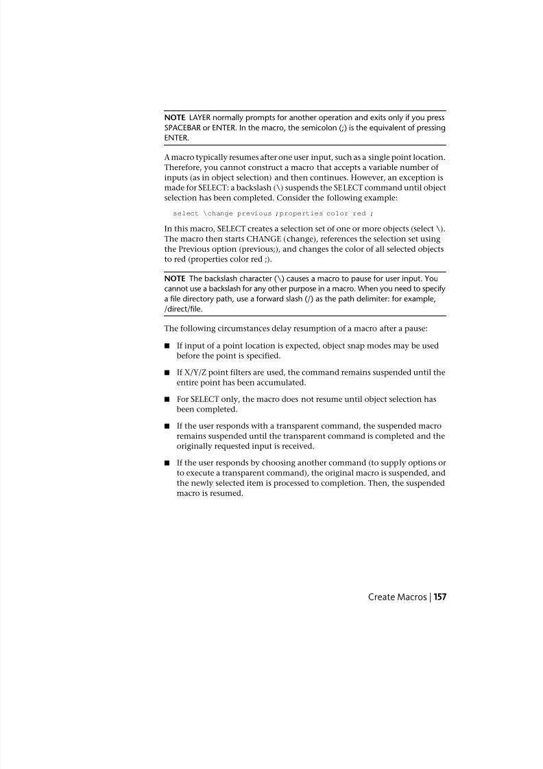
7/23/2019 Acad Customization
http://slidepdf.com/reader/full/acad-customization 165/553
NOTE LAYER normally prompts for another operation and exits only if you press
SPACEBAR or ENTER. In the macro, the semicolon (;) is the equivalent of pressing
ENTER.
A macro typically resumes after one user input, such as a single point location.
Therefore, you cannot construct a macro that accepts a variable number of
inputs (as in object selection) and then continues. However, an exception is
made for SELECT: a backslash (\) suspends the SELECT command until object
selection has been completed. Consider the following example:
select \change previous ;properties color red ;
In this macro, SELECT creates a selection set of one or more objects (select \).
The macro then starts CHANGE (change), references the selection set using
the Previous option (previous;), and changes the color of all selected objects
to red (properties color red ;).
NOTE The backslash character (\) causes a macro to pause for user input. You
cannot use a backslash for any other purpose in a macro. When you need to specify
a file directory path, use a forward slash (/) as the path delimiter: for example,
/direct/file.
The following circumstances delay resumption of a macro after a pause:
■ If input of a point location is expected, object snap modes may be used
before the point is specified.
■ If X/Y/Z point filters are used, the command remains suspended until the
entire point has been accumulated.
■ For SELECT only, the macro does not resume until object selection has
been completed.
■ If the user responds with a transparent command, the suspended macro
remains suspended until the transparent command is completed and the
originally requested input is received.
■ If the user responds by choosing another command (to supply options or
to execute a transparent command), the original macro is suspended, and
the newly selected item is processed to completion. Then, the suspended
macro is resumed.
Create Macros | 157
7/23/2019 Acad Customization
http://slidepdf.com/reader/full/acad-customization 166/553
NOTE When command input comes from a command, the settings of the PICKADD
and PICKAUTO system variables are assumed to be 1 and 0, respectively. This
preserves compatibility with previous releases of AutoCAD and makes customization
easier because you are not required to check the settings of these variables.
Quick Reference
Commands
CHANGE
Changes the properties of existing objects.
LAYER
Manages layers and layer properties.
SELECT
Places selected objects in the Previous selection set.
System Variables
PICKADD
Controls whether subsequent selections replace the current selection set or
add to it.
PICKAUTO
Controls automatic windowing at the Select Objects prompt.
Provide International Support in MacrosTo develop menus that can be used with a non-English-language version of
AutoCAD, precede each command or option with the underscore character
(_). The underscore character allows the standard commands and options to
be translated automatically.
Quick Reference
Commands
CUI
Manages the customized user interface elements in the product.
158 | Chapter 4 User Interface Customization
7/23/2019 Acad Customization
http://slidepdf.com/reader/full/acad-customization 167/553
Use Built-in Commands in Macros
To develop macros that use built-in commands that are part of AutoCAD,precede each command with the period character (.). The period character
allows the built-in command to be used even if it has been undefined with
the UNDEFINE command making the macro predicable when it is used on
other systems that share the same customization file.
Quick Reference
Commands
REDEFINE
Restores AutoCAD internal commands overridden by UNDEFINE.
UNDEFINE
Allows an application-defined command to override an internal command.
Repeat Commands in MacrosYou can use a leading asterisk (*) to repeat a command in a macro until you
choose another command.
Once you have selected a command, you might want to use it several times
before moving on to another command. In a macro, you can repeat a command
until you choose another command. You cannot use this feature to choose
options.
If a macro begins with *^C^C, the command is repeated until you terminateby pressing ESC on the keyboard or by selecting another command.
NOTE Do not use ^C (Cancel) within a macro that begins with the string *^C^C;
this cancels the repetition.
The macros in the following examples repeat the commands:
*^C^Cmove Single
*^C^Ccopy Single
*^C^Cerase Single
*^C^Cstretch Single Crossing
*^C^Crotate Single
*^C^Cscale Single
Create Macros | 159
7/23/2019 Acad Customization
http://slidepdf.com/reader/full/acad-customization 168/553
7/23/2019 Acad Customization
http://slidepdf.com/reader/full/acad-customization 169/553
user interface element of the same type in the main CUIx file, or it can come
from a partial CUIx file.
You cannot swap interface elements that are of different types (menus and
mouse buttons, for example). However, within a given type, you can swap
any user interface element for any other element.
NOTE Swapping can lead to some strange behavior for tablet menus, because
they typically have a different number of macros.
Use the following syntax in a macro to swap elements:
$section=customizationgroup.menuname
The following describes each section of the macro syntax for swapping
elements:
Macro syntax for swapping elements$ Loads an interface element
section Specifies the element type. Valid names are:
A1-A4 for Aux menus 1 through 4
B1-B4 for mouse buttons 1 through 4
P0-P16 for pull-down menus 0 through 16
I for the image tile menu
S for the screen menu
T1-T4 for tablet menus 1 through 4
customizationgroup Specifies the customization group that menuname is a
member of (not necessary if menuname is in the main CUIx file).
menuname Specifies which section or submenu to insert. It is the main label
or alias for the section to load
The following commands illustrate submenu referencing:
$S=PARTS
$T1=EDITCMDS
You can activate the submenu mechanism in the middle of a command
without interrupting the command. For example, the following command
strings are equivalent:
$S=ARCSTUFF ARC
ARC $S=ARCSTUFF
Create Macros | 161
7/23/2019 Acad Customization
http://slidepdf.com/reader/full/acad-customization 170/553
Each command starts the ARC command, switches to the ARCSTUFF screen
submenu, and awaits the entry of arc parameters. A space must follow the
submenu reference to separate it from subsequent commands in the command.
A pull-down menu can be present either in the menu bar or on the active
shortcut menu but not both.
Quick Reference
Commands
CUI
Manages the customized user interface elements in the product.
Use Conditional Expressions in MacrosYou can add conditional expressions to a macro by using a command that
introduces macro expressions written in DIESEL (Direct Interpretively Evaluated
String Expression Language).
The format is:
$M=expression
Introducing the macro with $M= tells AutoCAD to evaluate a string as a DIESEL
expression, and that expression is the DIESEL expression. The following
example defines a conditional expression in a macro:
FILLMODE $M=$(-,1,$(getvar,fillmode))
The macro switches the FILLMODE system variable on and off by subtracting
the current value of FILLMODE from 1 and returning the resulting value to
the FILLMODE system variable. You can use this method to toggle system
variables whose valid values are 1 or 0.
Termination of Macros That Contain Conditional Expressions
If you use the DIESEL string language to perform “if-then” tests, conditions
might exist where you do not want the normal terminating space or semicolon
(resulting in ENTER). If you add ^Z to the end of the macro, AutoCAD does
not automatically add a space (ENTER) to the end of the macro expression.
As with other control characters in commands, the ^Z used here is a string
composed of ^ (a caret) and Z and is not equivalent to pressing Ctrl+Z.
162 | Chapter 4 User Interface Customization
7/23/2019 Acad Customization
http://slidepdf.com/reader/full/acad-customization 171/553
In the following examples, ^Z is used as a macro terminator.
^C^C$M=$(if,$(=,$(getvar,tilemode),0),$S=mview _mspace )^Z^C^C$M=$(if,$(=,$(getvar,tilemode),0),$S=mview _pspace )^Z
If these macros did not end with ^Z, AutoCAD would automatically add a
space (ENTER), repeating the last command entered.
See also:
■ Use Special Control Characters in Macros on page 154
■ DIESEL on page 393
Quick Reference
Commands
CUI
Manages the customized user interface elements in the product.
System Variables
FILLMODE
Specifies whether hatches and fills, 2D solids, and wide polylines are filled
in.
Use AutoLISP in MacrosCreating commands that use AutoLISP is a more advanced way to use the
AutoCAD customization feature.
You can use AutoLISP variables and expressions to create macros that perform
complex tasks. To use AutoLISP efficiently in macros, place AutoLISP code in
a separate MNL file. AutoCAD loads the MNL file when it loads a CUIx file
with the same name and in the same location.
You can specify additional AutoLISP files to load in the Customize User
Interface (CUI) Editor. Creating commands that use AutoLISP is a more
advanced way to use the AutoCAD customization feature. Carefully study the
following examples and the information in the AutoLISP Reference and the
AutoLISP Developer's Guide . To access the additional help resources, on the
InfoCenter toolbar, to the right of the Help button, click the drop-down arrow.Experimentation and practice will help you use this feature effectively.
Create Macros | 163
7/23/2019 Acad Customization
http://slidepdf.com/reader/full/acad-customization 172/553
Call a Macro
To programmatically execute a pull-down menu macro, use the followingsyntax:
(menucmd "Gcustomizationgroup .element_ID =|")
The previous syntax works only if the menu macro is part of a menu that is
on the AutoCAD menu bar and is available for use. For more information
about this syntax, see the AutoLISP Reference .
Preset Values
An application that uses block insertion presets could provide commands like
these: [Set WINWID][Set WALLTHK][Insert Window]
^C^C P(setq WINWID (getreal "Enter window width: ")) ^P
^C^C P(setq WALLTHK (getreal "Enter wall thickness: ")) ^P
^C^C_INSERT window XScale !WINWID YScale !WALLTHK
This code inserts the block named “window,” scaling its X axis to the current
window width and its Y axis to the current wall thickness. In this example,
the actual values come from the user-defined AutoLISP symbols WINWID and
WALLTHK. The rotation is up to the user to decide so that the window can
be rotated in the wall.
Resize Grips
With the following commands, grip size adjustment can be done on the fly:
^P(setvar "gripsize"(1+ (getvar "gripsize")))(redraw)(princ)
^P(setvar "gripsize"(1- (getvar "gripsize")))(redraw)(princ)
To add validity checking to these commands, values less than 0 and greater
than 255 cannot be used for the GRIPSIZE system variable.
Prompt for User Input
The following item prompts for two points and draws a rectangular polyline
with the specified points as its corners.
^P(setq a (getpoint "Enter first corner: "));\+
(setq b (getpoint "Enter opposite corner: "));\+
pline !a (list (car a)(cadr b)) !b (list (car b)(cadr a)) c;^P
164 | Chapter 4 User Interface Customization
7/23/2019 Acad Customization
http://slidepdf.com/reader/full/acad-customization 173/553
Quick Reference
Commands
CUI
Manages the customized user interface elements in the product.
Control the Display of Command ItemsThe way a menu or ribbon button item is displayed indicates its availability
in the program. A menu or ribbon button item can be displayed as:
■ Grayed out (disabled)
■ Marked with a check marker or border
■ Both grayed out and marked
Ribbon button items do not display a check mark when marked; only a border
is displayed.
NOTE To disable or mark ribbon button items, the “~” or “!.” sequence cannot
be placed before a command name explicitly; it must be inside a DIESEL expression.
Gray Out (Disable) Menu or Ribbon Button Items
You gray out a menu or ribbon button item by doing one of the following:
■ Beginning a name with a tilde (~)
■ Using a DIESEL string expression
Ribbon button items only support the use of DIESEL string expressions. For
more information about using DIESEL expressions, see DIESEL Expressions in
Macros. When grayed out, the macro and submenus associated with the menu
or ribbon button item are made inaccessible.
In the following example, the tilde (~) is placed at the beginning of the Copy
Link command label in the Name cell of the Properties pane.
Control the Display of Command Items | 165
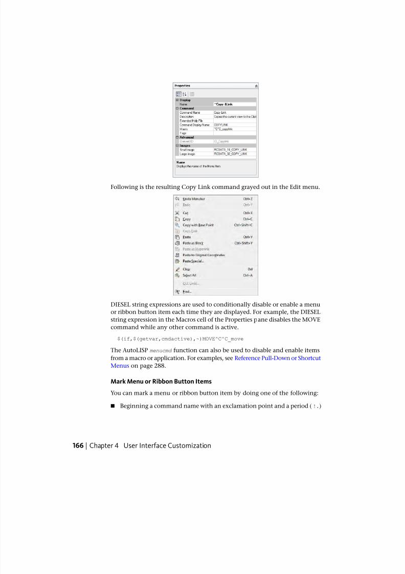
7/23/2019 Acad Customization
http://slidepdf.com/reader/full/acad-customization 174/553
Following is the resulting Copy Link command grayed out in the Edit menu.
DIESEL string expressions are used to conditionally disable or enable a menu
or ribbon button item each time they are displayed. For example, the DIESEL
string expression in the Macros cell of the Properties pane disables the MOVE
command while any other command is active.
$(if,$(getvar,cmdactive),~)MOVE^C^C_move
The AutoLISP menucmd function can also be used to disable and enable items
from a macro or application. For examples, see Reference Pull-Down or Shortcut
Menus on page 288.
Mark Menu or Ribbon Button Items
You can mark a menu or ribbon button item by doing one of the following:
■ Beginning a command name with an exclamation point and a period (!.)
166 | Chapter 4 User Interface Customization
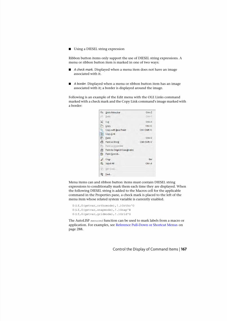
7/23/2019 Acad Customization
http://slidepdf.com/reader/full/acad-customization 175/553
■ Using a DIESEL string expression
Ribbon button items only support the use of DIESEL string expressions. A
menu or ribbon button item is marked in one of two ways:
■ A check mark. Displayed when a menu item does not have an image
associated with it.
■ A border. Displayed when a menu or ribbon button item has an image
associated with it; a border is displayed around the image.
Following is an example of the Edit menu with the OLE Links command
marked with a check mark and the Copy Link command's image marked with
a border:
Menu items can and ribbon button items must contain DIESEL string
expressions to conditionally mark them each time they are displayed. When
the following DIESEL string is added to the Macros cell for the applicable
command in the Properties pane, a check mark is placed to the left of the
menu item whose related system variable is currently enabled.
$(if,$(getvar,orthomode),!.)Ortho^O
$(if,$(getvar,snapmode),!.)Snap^B
$(if,$(getvar,gridmode),!.)Grid^G
The AutoLISP menucmd function can be used to mark labels from a macro or
application. For examples, see Reference Pull-Down or Shortcut Menus onpage 288.
Control the Display of Command Items | 167
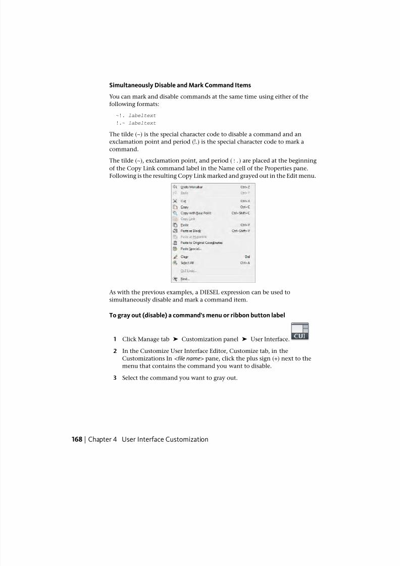
7/23/2019 Acad Customization
http://slidepdf.com/reader/full/acad-customization 176/553
Simultaneously Disable and Mark Command Items
You can mark and disable commands at the same time using either of thefollowing formats:
~!. labeltext
!.~ labeltext
The tilde (~) is the special character code to disable a command and an
exclamation point and period (!.) is the special character code to mark a
command.
The tilde (~), exclamation point, and period (!.) are placed at the beginning
of the Copy Link command label in the Name cell of the Properties pane.
Following is the resulting Copy Link marked and grayed out in the Edit menu.
As with the previous examples, a DIESEL expression can be used to
simultaneously disable and mark a command item.
To gray out (disable) a command's menu or ribbon button label
1 Click Manage tab ➤ Customization panel ➤ User Interface.
2 In the Customize User Interface Editor, Customize tab, in the
Customizations In <file name> pane, click the plus sign (+) next to the
menu that contains the command you want to disable.
3 Select the command you want to gray out.
168 | Chapter 4 User Interface Customization
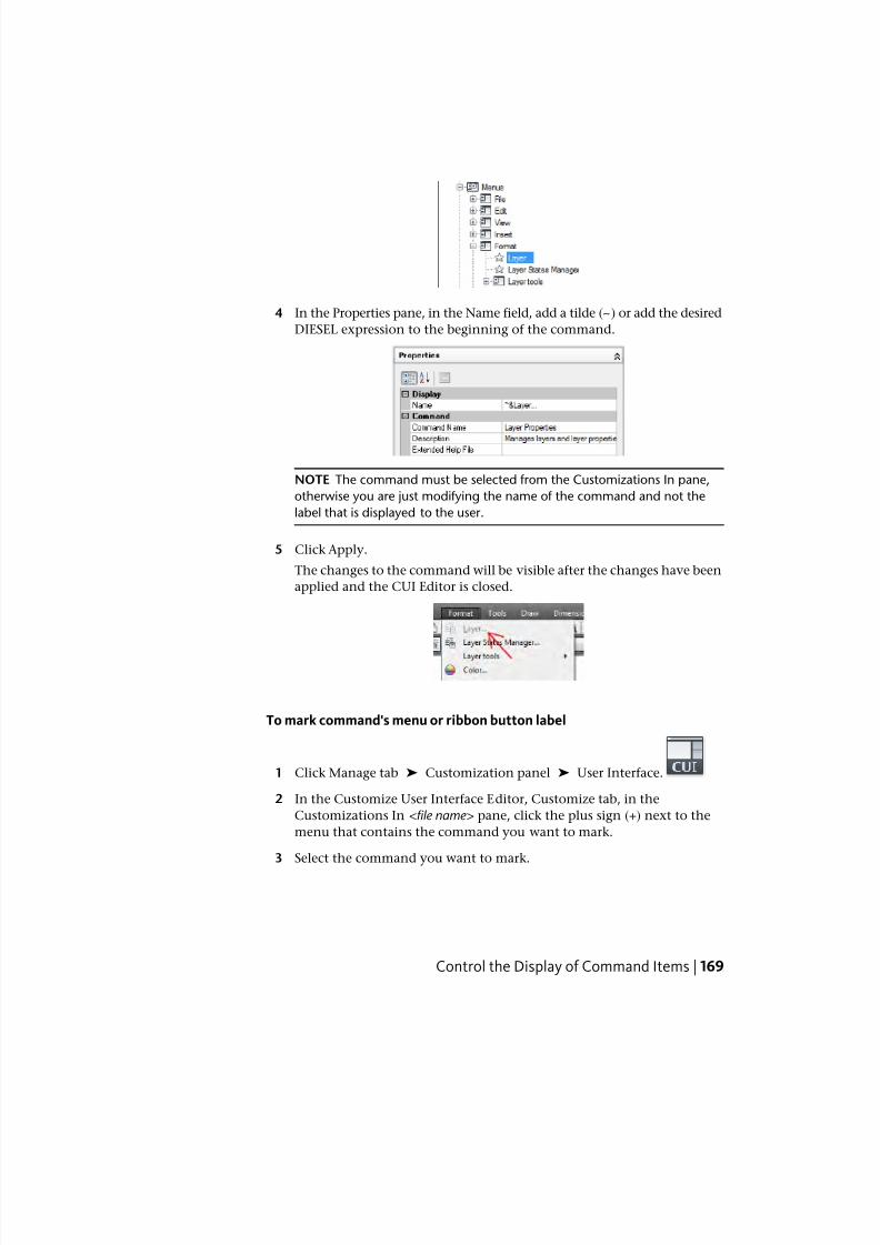
7/23/2019 Acad Customization
http://slidepdf.com/reader/full/acad-customization 177/553
4 In the Properties pane, in the Name field, add a tilde (~) or add the desired
DIESEL expression to the beginning of the command.
NOTE The command must be selected from the Customizations In pane,
otherwise you are just modifying the name of the command and not the
label that is displayed to the user.
5 Click Apply.
The changes to the command will be visible after the changes have been
applied and the CUI Editor is closed.
To mark command's menu or ribbon button label
1 Click Manage tab ➤ Customization panel ➤ User Interface.
2 In the Customize User Interface Editor, Customize tab, in the
Customizations In <file name> pane, click the plus sign (+) next to the
menu that contains the command you want to mark.
3 Select the command you want to mark.
Control the Display of Command Items | 169
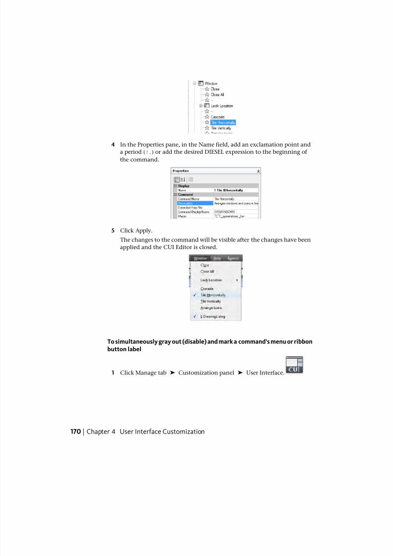
7/23/2019 Acad Customization
http://slidepdf.com/reader/full/acad-customization 178/553
4 In the Properties pane, in the Name field, add an exclamation point and
a period (!.) or add the desired DIESEL expression to the beginning of
the command.
5 Click Apply.
The changes to the command will be visible after the changes have been
applied and the CUI Editor is closed.
To simultaneously gray out (disable) and mark a command's menu or ribbonbutton label
1 Click Manage tab ➤ Customization panel ➤ User Interface.
170 | Chapter 4 User Interface Customization
7/23/2019 Acad Customization
http://slidepdf.com/reader/full/acad-customization 179/553
2 In the Customize User Interface Editor, Customize tab, in the
Customizations In <file name> pane, click the plus sign (+) next to the
menu that contains the command you want to disable and mark.
3 Select the command you want to gray out and mark.
4 In the Properties pane, in the Name field, add a tilde, an exclamation
point, and a period (~!. or !.~) or add the desired DIESEL expression to
the beginning of the command.
5 Click Apply.
Quick Reference
Commands
CUI
Manages the customized user interface elements in the product.
Assign Search TagsWith search tags, you can search for a command or a group of commands
with the application menu.
You can assign one or more tags to a command to make it easy to locate when
performing a search from the application menu. You add tags to a command
using the Tag Editor dialog box. When a tag is assigned to a command, it is
displayed on a tooltip (when the command is on a toolbar or ribbon panel
and the cursor hovers over the command).
You can change the display of tooltips on the Display tab of the Options dialog
box. See Search for Commands in the User ’ s Guide to learn more about using
search in the application menu.
To add tags to a command
1 Click Manage tab ➤ Customization panel ➤ User Interface.
2 In the Customize User Interface Editor, Customize tab, Command List
pane, select the command to which you want to add a tag.
Assign Search Tags | 171
7/23/2019 Acad Customization
http://slidepdf.com/reader/full/acad-customization 180/553
3 In the Properties pane, select the Tags field and click the [ ] button.
4 In the Tag Editor dialog box, in the Tags box, enter a tag.
As you enter a tag, a popup menu might display showing a list of
previously used tags. Click a tag on the menu to use that tag. You canadd more than one tag to a command; separate each tag with a comma.
5 To add another tag for a command, press the Left Arrow key and enter
the tag. Repeat as needed.
6 Click OK.
172 | Chapter 4 User Interface Customization
7/23/2019 Acad Customization
http://slidepdf.com/reader/full/acad-customization 181/553
7 In the Customize User Interface Editor, click Apply.
To remove a tag from a command
1 Click Manage tab ➤ Customization panel ➤ User Interface.
2 In the Customize User Interface Editor, Customize tab, Command List
pane, select the command from which you want to remove a tag.
The Properties pane is displayed on the right side.
3 In the Properties pane, select the Tags field and click the [ ] button.
4 In the Tag Editor dialog box, in the Tags box, click the tag you want to
remove. Press Delete.
Assign Search Tags | 173

7/23/2019 Acad Customization
http://slidepdf.com/reader/full/acad-customization 182/553
The tag is removed.
5 Click OK.
6 In the Customize User Interface Editor, click Apply.
Quick Reference
Commands
CUI
Manages the customized user interface elements in the product.
OPTIONS
Customizes the program settings.
Create Tooltips and Extended Help for CommandsTooltips are descriptive messages that are displayed near the cursor when it
hovers over a toolbar or panel button, or menu item.
The Description property associated to a command provides a simple
description for what the command does. The value of the Description property
is displayed as part of a basic tooltip that is displayed when the cursor hovers
over a button on a toolbar, or ribbon panel. Along with the description, a
command tooltip also displays the name of the command, and the values
assigned to the Command Display Name and Tags properties.
Additionally, a command can be assigned an extended help file and ID so it
can display a second level of information for the command. The content from
the extended help file is displayed in the extended description area of a tooltip.
The content for the extended description area of a tooltip is stored in an XAML
file, and can contain rich-text and images.
174 | Chapter 4 User Interface Customization
7/23/2019 Acad Customization
http://slidepdf.com/reader/full/acad-customization 183/553
Control the Display of Tooltips
You control the display of tooltips and when the extended help assigned toa command is displayed from the Options dialog box. See Set Interface Options
in the User ’ s Guide to learn more about tooltips.
Example of an XAML File
The XAML structure is a format that was developed by Microsoft. The following
is an example of what an XAML file might look like for two custom commands
that exist in your CUIx file.
<ResourceDictionary
xmlns="http://schemas.microsoft.com/winfx/2006/xaml/presentation"
xmlns:x="http://schemas.microsoft.com/winfx/2006/xaml"
xmlns:src="clr-namespace:Autodesk.Windows;assembly=AdWindows">
<src:RibbonToolTip x:Key="MYEH_CMD_0001">
<src:RibbonToolTip.ExpandedContent>
<StackPanel>
<TextBlock Background="AntiqueWhite" TextAlignment="Center">
Creates a rectangular revision cloud on the <Bold>REVISION</Bold>
layer.
</TextBlock>
<Image Source="images/rectcloud.jpg" Width="Auto" Height="Auto">
</Image>
</StackPanel>
</src:RibbonToolTip.ExpandedContent>
</src:RibbonToolTip>
<src:RibbonToolTip x:Key="MYEH_CMD_0002">
<src:RibbonToolTip.ExpandedContent>
<StackPanel>
<TextBlock Background="Yellow" TextAlignment="Left">
Creates a polygonal revision cloud on the
<Run Text=" REVISION " Foreground="Red" FontStyle="Italic"/>
layer.
</TextBlock>
<Image Source="images/rectcloud.jpg" Width="Auto" Height="Auto">
</Image>
</StackPanel>
</src:RibbonToolTip.ExpandedContent>
</src:RibbonToolTip>
</ResourceDictionary>
The ResourceDictionary element is used to define the type of content that is
in the XAML file; while the scr:RibbonToolTip element is used to define each
Create Tooltips and Extended Help for Commands | 175
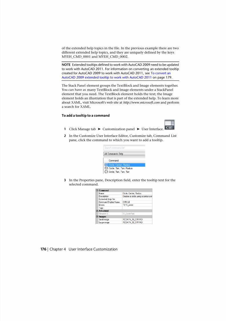
7/23/2019 Acad Customization
http://slidepdf.com/reader/full/acad-customization 184/553
of the extended help topics in the file. In the previous example there are two
different extended help topics, and they are uniquely defined by the keys
MYEH_CMD_0001 and MYEH_CMD_0002.
NOTE Extended tooltips defined to work with AutoCAD 2009 need to be updated
to work with AutoCAD 2011. For information on converting an extended tooltip
created for AutoCAD 2009 to work with AutoCAD 2011, see To convert an
AutoCAD 2009 extended tooltip to work with AutoCAD 2011 on page 179.
The Stack Panel element groups the TextBlock and Image elements together.
You can have as many TextBlock and Image elements under a StackPanel
element that you need. The TextBlock element holds the text; the Image
element holds an illustration that is part of the extended help. To learn more
about XAML, visit Microsoft's web site at http://www.microsoft.com and perform
a search for XAML.
To add a tooltip to a command
1 Click Manage tab ➤ Customization panel ➤ User Interface.
2 In the Customize User Interface Editor, Customize tab, Command List
pane, click the command to which you want to add a tooltip.
3 In the Properties pane, Description field, enter the tooltip text for the
selected command.
176 | Chapter 4 User Interface Customization
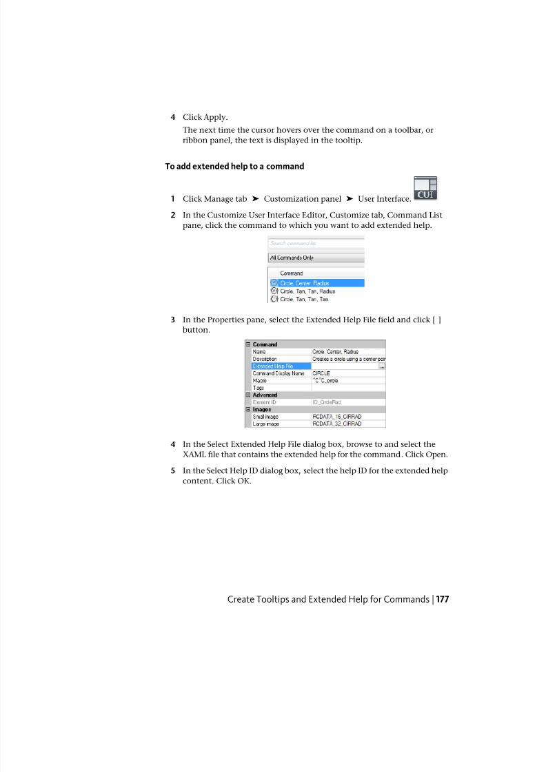
7/23/2019 Acad Customization
http://slidepdf.com/reader/full/acad-customization 185/553
4 Click Apply.
The next time the cursor hovers over the command on a toolbar, or
ribbon panel, the text is displayed in the tooltip.
To add extended help to a command
1 Click Manage tab ➤ Customization panel ➤ User Interface.
2 In the Customize User Interface Editor, Customize tab, Command List
pane, click the command to which you want to add extended help.
3 In the Properties pane, select the Extended Help File field and click [ ]button.
4 In the Select Extended Help File dialog box, browse to and select the
XAML file that contains the extended help for the command. Click Open.
5 In the Select Help ID dialog box, select the help ID for the extended help
content. Click OK.
Create Tooltips and Extended Help for Commands | 177
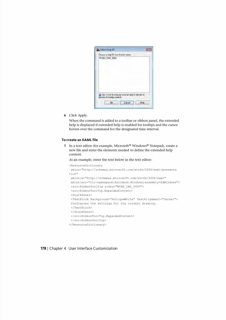
7/23/2019 Acad Customization
http://slidepdf.com/reader/full/acad-customization 186/553
6 Click Apply.
When the command is added to a toolbar or ribbon panel, the extended
help is displayed if extended help is enabled for tooltips and the cursor
hovers over the command for the designated time interval.
To create an XAML file
1 In a text editor (for example, Microsoft® Windows® Notepad), create a
new file and enter the elements needed to define the extended help
content.
As an example, enter the text below in the text editor:
<ResourceDictionary
xmlns="http://schemas.microsoft.com/winfx/2006/xaml/presenta
tion"
xmlns:x="http://schemas.microsoft.com/winfx/2006/xaml"
xmlns:src="clr-namespace:Autodesk.Windows;assembly=AdWindows">
<src:RibbonToolTip x:Key="MYEH_CMD_0003">
<src:RibbonToolTip.ExpandedContent>
<StackPanel>
<TextBlock Background="AntiqueWhite" TextAlignment="Center">
Configures the settings for the current drawing.
</TextBlock>
</StackPanel>
</src:RibbonToolTip.ExpandedContent>
</src:RibbonToolTip>
</ResourceDictionary>
178 | Chapter 4 User Interface Customization

7/23/2019 Acad Customization
http://slidepdf.com/reader/full/acad-customization 187/553
2 Save the file as ASCII text (TXT file), with a file extension of .xaml .
To convert an AutoCAD 2009 extended tooltip to work with AutoCAD 2011
1 Open the XAML file in a text editor (for example, Microsoft® Windows®
Notepad).
The following is an example of an extended tooltip created to use with
AutoCAD 2009. You change the text shown in italic.
<src:ProgressivePanel x:Key="MYEH_CMD_0003">
<StackPanel>
<TextBlock Background="AntiqueWhite" TextAlignment="Center">
Configures the settings for the current drawing.
</TextBlock>
</StackPanel>
</src:ProgressivePanel >
2 Change the text shown in italic in the previous step to match the
following:
<src:RibbonToolTip x:Key="MYEH_CMD_0003">
<src:RibbonToolTip.ExpandedContent>
<StackPanel>
<TextBlock Background="AntiqueWhite" TextAlignment="Center">
Configures the settings for the current drawing.
</TextBlock>
</StackPanel>
</src:RibbonToolTip.ExpandedContent>
</src:RibbonToolTip >
3 Save the changes made to the XAML file.
Quick Reference
Commands
CUI
Manages the customized user interface elements in the product.
OPTIONS
Customizes the program settings.
Create Tooltips and Extended Help for Commands | 179
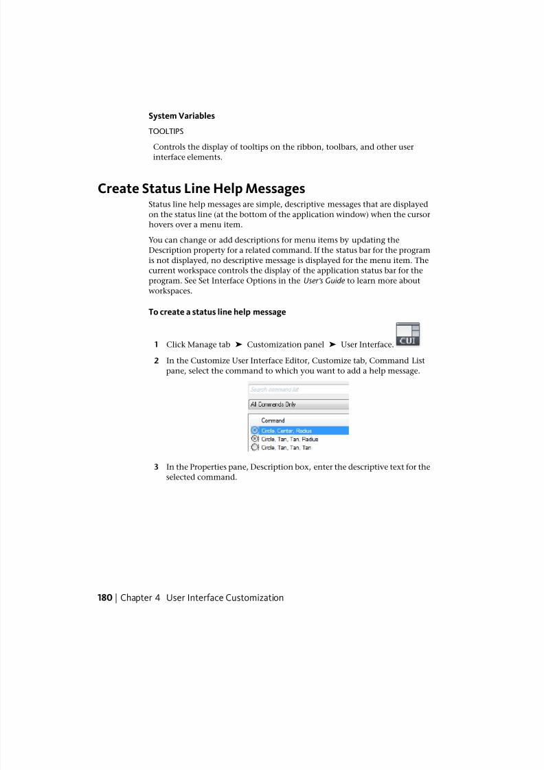
7/23/2019 Acad Customization
http://slidepdf.com/reader/full/acad-customization 188/553
System Variables
TOOLTIPSControls the display of tooltips on the ribbon, toolbars, and other user
interface elements.
Create Status Line Help MessagesStatus line help messages are simple, descriptive messages that are displayed
on the status line (at the bottom of the application window) when the cursor
hovers over a menu item.
You can change or add descriptions for menu items by updating the
Description property for a related command. If the status bar for the program
is not displayed, no descriptive message is displayed for the menu item. The
current workspace controls the display of the application status bar for theprogram. See Set Interface Options in the User ’ s Guide to learn more about
workspaces.
To create a status line help message
1 Click Manage tab ➤ Customization panel ➤ User Interface.
2 In the Customize User Interface Editor, Customize tab, Command List
pane, select the command to which you want to add a help message.
3 In the Properties pane, Description box, enter the descriptive text for the
selected command.
180 | Chapter 4 User Interface Customization
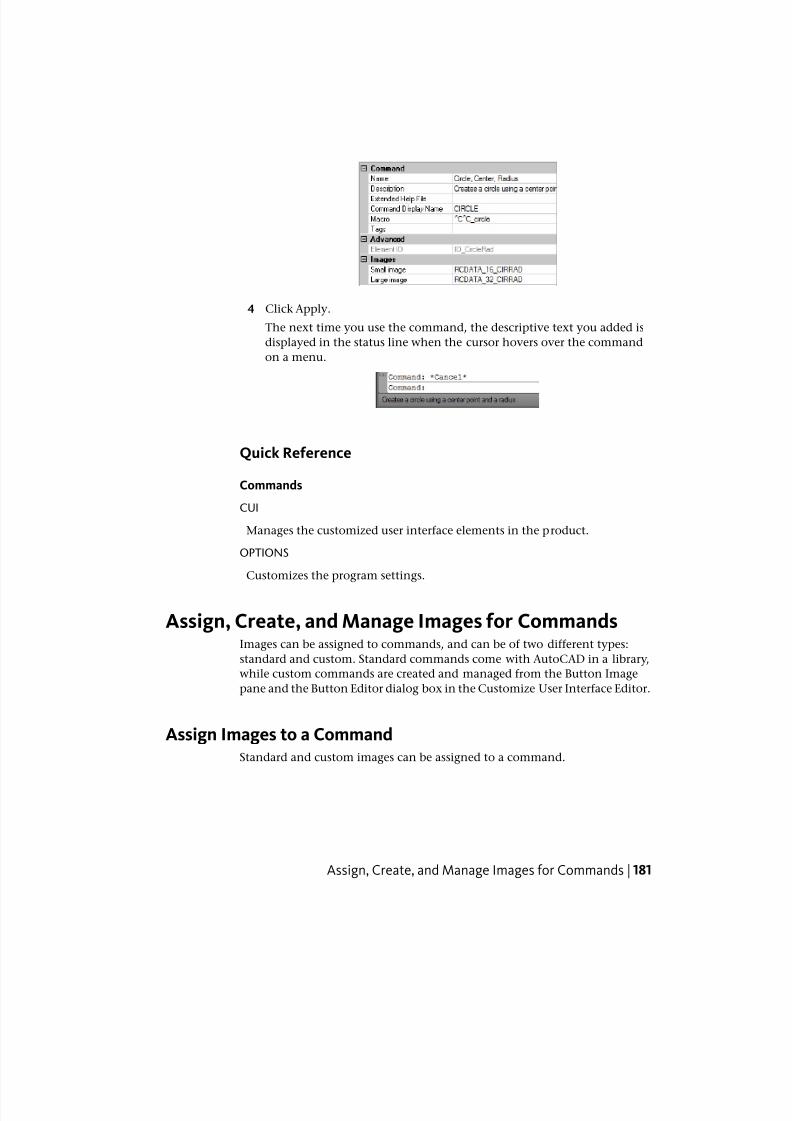
7/23/2019 Acad Customization
http://slidepdf.com/reader/full/acad-customization 189/553
4 Click Apply.
The next time you use the command, the descriptive text you added is
displayed in the status line when the cursor hovers over the command
on a menu.
Quick Reference
Commands
CUI
Manages the customized user interface elements in the product.
OPTIONS
Customizes the program settings.
Assign, Create, and Manage Images for CommandsImages can be assigned to commands, and can be of two different types:
standard and custom. Standard commands come with AutoCAD in a library,
while custom commands are created and managed from the Button Image
pane and the Button Editor dialog box in the Customize User Interface Editor.
Assign Images to a CommandStandard and custom images can be assigned to a command.
Assign, Create, and Manage Images for Commands | 181
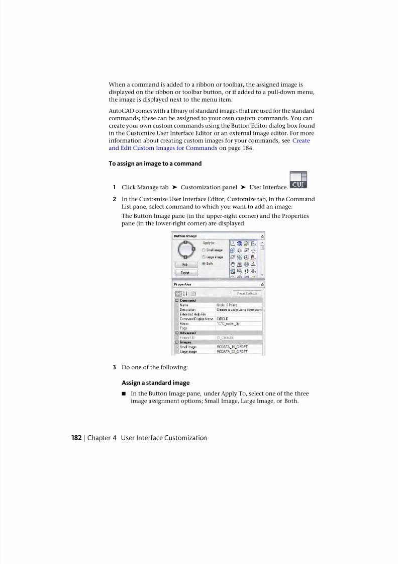
7/23/2019 Acad Customization
http://slidepdf.com/reader/full/acad-customization 190/553
When a command is added to a ribbon or toolbar, the assigned image is
displayed on the ribbon or toolbar button, or if added to a pull-down menu,
the image is displayed next to the menu item.
AutoCAD comes with a library of standard images that are used for the standard
commands; these can be assigned to your own custom commands. You can
create your own custom commands using the Button Editor dialog box found
in the Customize User Interface Editor or an external image editor. For more
information about creating custom images for your commands, see Create
and Edit Custom Images for Commands on page 184.
To assign an image to a command
1 Click Manage tab ➤ Customization panel ➤ User Interface.
2 In the Customize User Interface Editor, Customize tab, in the CommandList pane, select command to which you want to add an image.
The Button Image pane (in the upper-right corner) and the Properties
pane (in the lower-right corner) are displayed.
3 Do one of the following:
Assign a standard image
■ In the Button Image pane, under Apply To, select one of the threeimage assignment options; Small Image, Large Image, or Both.
182 | Chapter 4 User Interface Customization
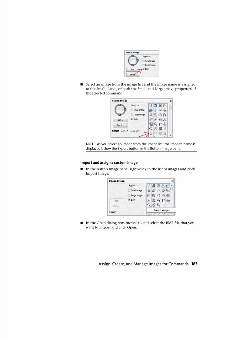
7/23/2019 Acad Customization
http://slidepdf.com/reader/full/acad-customization 191/553
■ Select an image from the image list and the image name is assigned
to the Small, Large, or both the Small and Large image properties of
the selected command.
NOTE As you select an image from the image list, the image’s name is
displayed below the Export button in the Button Image pane.
Import and assign a custom image
■ In the Button Image pane, right-click in the list of images and click
Import Image.
■ In the Open dialog box, browse to and select the BMP file that you
want to import and click Open.
Assign, Create, and Manage Images for Commands | 183

7/23/2019 Acad Customization
http://slidepdf.com/reader/full/acad-customization 192/553
■ In the Button Image pane, under Apply To, select one of the three
image assignment options; Small Image, Large Image, or Both. Then
select the image you imported from the image list.
4 Click Apply.
Quick Reference
Commands
CUI
Manages the customized user interface elements in the product.
Create and Edit Custom Images for CommandsCustom images can be created and edited which can be assigned to a
command.
You can create custom images to assign to a command using the Button Editor
dialog box built into the CUI Editor or an external image editor. You can
either start with an existing button image or create your own from scratch.
Custom images when saved are by default stored in the working customization
file. Saved custom images can be exported to an external BMP file to use in
another customization file.
NOTE In releases prior to AutoCAD 2011, custom images were stored separately
from the customization file. In AutoCAD 2011, images are now stored as part of
the CUIx file making it easier to share with others.
Custom images can be created in two different sizes: small and large. Small
images should be 16 x 16 pixels. Large images should be 32 x 32 pixels. Images
that do not match these sizes are scaled to fit.
184 | Chapter 4 User Interface Customization
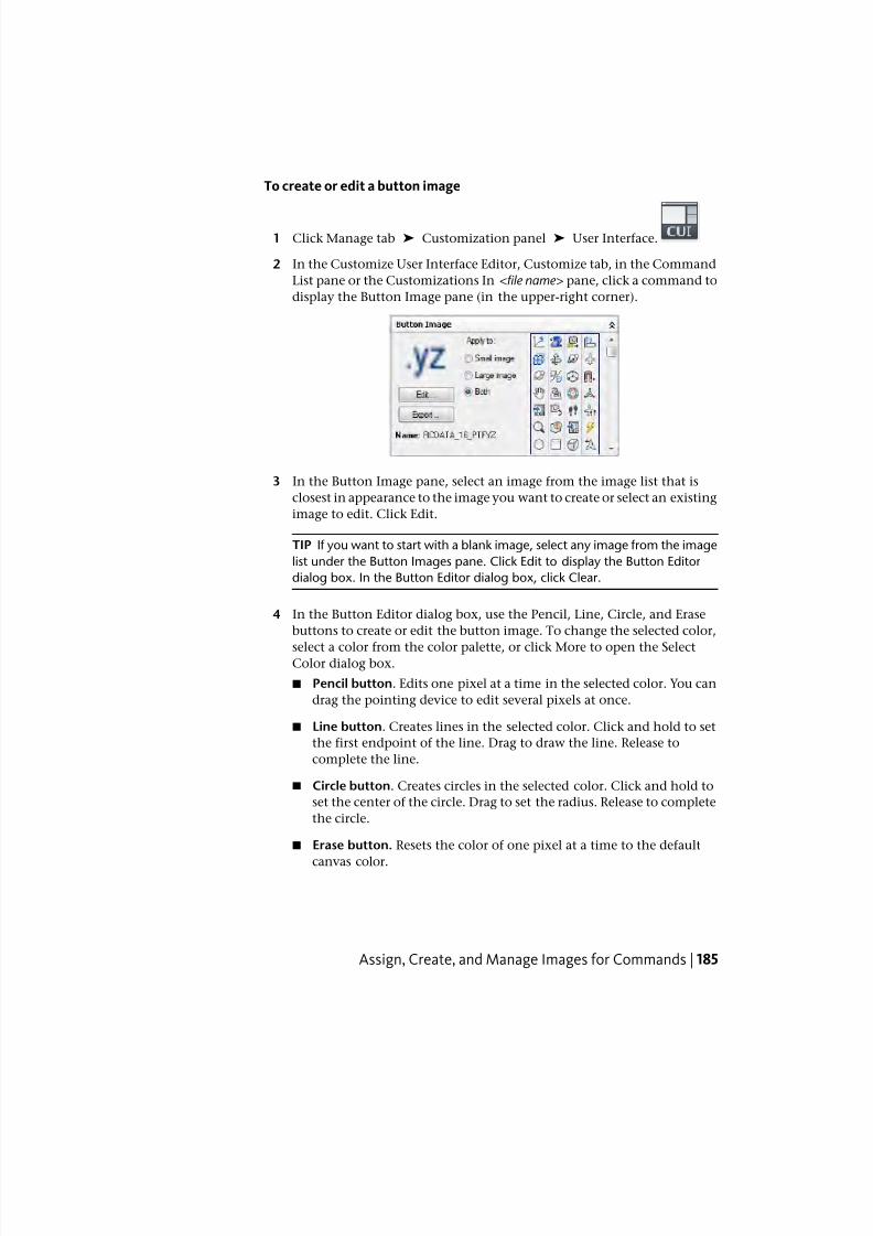
7/23/2019 Acad Customization
http://slidepdf.com/reader/full/acad-customization 193/553
To create or edit a button image
1 Click Manage tab ➤ Customization panel ➤ User Interface.
2 In the Customize User Interface Editor, Customize tab, in the Command
List pane or the Customizations In <file name> pane, click a command to
display the Button Image pane (in the upper-right corner).
3 In the Button Image pane, select an image from the image list that is
closest in appearance to the image you want to create or select an existing
image to edit. Click Edit.
TIP If you want to start with a blank image, select any image from the image
list under the Button Images pane. Click Edit to display the Button Editor
dialog box. In the Button Editor dialog box, click Clear.
4 In the Button Editor dialog box, use the Pencil, Line, Circle, and Erase
buttons to create or edit the button image. To change the selected color,
select a color from the color palette, or click More to open the SelectColor dialog box.
■ Pencil button. Edits one pixel at a time in the selected color. You can
drag the pointing device to edit several pixels at once.
■ Line button. Creates lines in the selected color. Click and hold to set
the first endpoint of the line. Drag to draw the line. Release to
complete the line.
■ Circle button. Creates circles in the selected color. Click and hold to
set the center of the circle. Drag to set the radius. Release to complete
the circle.
■ Erase button. Resets the color of one pixel at a time to the default
canvas color.
Assign, Create, and Manage Images for Commands | 185
7/23/2019 Acad Customization
http://slidepdf.com/reader/full/acad-customization 194/553
NOTE Click Import to import a BMP file stored on a local or network drive
to edit it in the Button Editor dialog box and store it in the working CUIx file.
5 Click Save.
The Save Image dialog box is displayed.
6 In the Save Image dialog box, Image Name text box, enter a name and
click OK.
The image is saved to the working CUIx file.
7 Click Close.
You are returned to the Customize User Interface Editor.
Quick Reference
Commands
CUI
Manages the customized user interface elements in the product.
Manage, Import, and Export Custom ImagesCustom images stored as externally saved BMP files can be imported into a
loaded customization file and exported from a customization file to a local or
network drive. Custom images can be deleted from a customization file in the
Image Manager.
Prior to AutoCAD 2011, custom images used for commands in a customization
file were stored on a local or network drive as separate BMP files or in a resource
DLL. Resource DLLs are still maintained externally to customization files but
starting with AutoCAD 2011, BMP files used by custom commands defined
in a customization file are stored in the customization file.
You can use the Image Manager, the Button Editor dialog box, or the Button
Image pane to manage custom images in the loaded customization files. With
the Image Manager, you can import and export custom images to and from
a customization file. You can also use the Image Manager to see which custom
images are currently stored in a loaded customization file and remove those
that you no longer need. You can also use the Button Editor dialog box and
Button Image pane to import and export custom images.
186 | Chapter 4 User Interface Customization
7/23/2019 Acad Customization
http://slidepdf.com/reader/full/acad-customization 195/553
To import a custom image to the image list and the working customizationfile
1 Click Manage tab ➤ Customization panel ➤ User Interface.
2 In the Customize User Interface Editor, Customize tab, in the Command
List pane, select any command to display the Button Image pane.
3 In the Button Image pane, right-click the image list and click Import
Image.
4 In the Open dialog box, browse to and select the BMP file that you want
to import and click Open.
The image is added to the image list and can then be assigned to a
command.
To export an image from the image list
1 Click Manage tab ➤ Customization panel ➤ User Interface.
2 In the Customize User Interface Editor, Customize tab, in the Command
List pane, select any command to display the Button Image pane.
3 In the Button Image pane, select the image to export, and click Export.
Assign, Create, and Manage Images for Commands | 187
7/23/2019 Acad Customization
http://slidepdf.com/reader/full/acad-customization 196/553
4 In the Export Image File dialog box, browse to the folder to which you
want to export the image and enter a name for the image in the File Name
text box.
5 Click Save.
NOTE You can only export images in the BMP (*.bmp, *.rle , or *.dib) format.
To import an image into a loaded customization file using the Image Manager
1 Click Manage tab ➤ Customization panel ➤ User Interface.
2 In the Customize User Interface Editor, Customize tab, in the
Customizations In <file name > pane, click Launches the Image Manager
Dialog.
3 In the Image Manager, Loaded Customization Files drop-down list, select
the loaded customization file into which you want to import a custom
image.
188 | Chapter 4 User Interface Customization
7/23/2019 Acad Customization
http://slidepdf.com/reader/full/acad-customization 197/553
4 In the Import Images dialog box, browse to and select the images you
want to import. Click Open.
If the CUI Editor - Image Already Exists dialog box is displayed, click
Import Image as Copy to create a copy of the image being imported or
Overwrite Existing Image to replace the image with the one being
imported.
5 Click OK.
To export an image from a loaded customization file with the Image Manager
1 Click Manage tab ➤ Customization panel ➤ User Interface.
2 In the Customize User Interface Editor, Customize tab, in the
Customizations In <file name > pane, click Launches the Image Manager
Dialog.
3 In the Image Manager, Loaded Customization Files drop-down list, select
the loaded customization file that contains the custom image you want
to export.
Assign, Create, and Manage Images for Commands | 189
7/23/2019 Acad Customization
http://slidepdf.com/reader/full/acad-customization 198/553
4 In the Custom Images list, select the image you want to export and click
Export.
5 In the Browse For Folder dialog box, browse to the folder to which you
want to export the selected images. Click OK.
6 Click OK.
To delete an image from a loaded customization file
1 Click Manage tab ➤ Customization panel ➤ User Interface.
2 In the Customize User Interface Editor, Customize tab, in the
Customizations In <file name > pane, click Launches the Image Manager
Dialog.
3 In the Image Manager, Loaded Customization Files drop-down list, select
the loaded customization file that contains the custom image that you
want to delete.
190 | Chapter 4 User Interface Customization
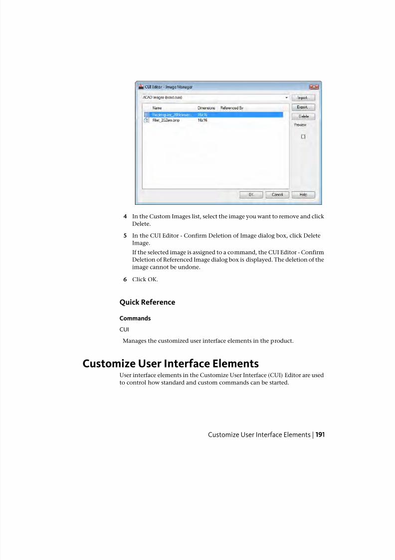
7/23/2019 Acad Customization
http://slidepdf.com/reader/full/acad-customization 199/553
4 In the Custom Images list, select the image you want to remove and click
Delete.
5 In the CUI Editor - Confirm Deletion of Image dialog box, click Delete
Image.
If the selected image is assigned to a command, the CUI Editor - Confirm
Deletion of Referenced Image dialog box is displayed. The deletion of the
image cannot be undone.
6 Click OK.
Quick Reference
Commands
CUI
Manages the customized user interface elements in the product.
Customize User Interface ElementsUser interface elements in the Customize User Interface (CUI) Editor are used
to control how standard and custom commands can be started.
Customize User Interface Elements | 191
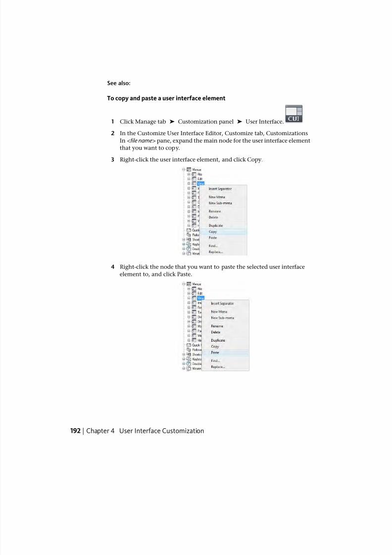
7/23/2019 Acad Customization
http://slidepdf.com/reader/full/acad-customization 200/553
See also:
To copy and paste a user interface element
1 Click Manage tab ➤ Customization panel ➤ User Interface.
2 In the Customize User Interface Editor, Customize tab, Customizations
In <file name> pane, expand the main node for the user interface element
that you want to copy.
3 Right-click the user interface element, and click Copy.
4 Right-click the node that you want to paste the selected user interface
element to, and click Paste.
192 | Chapter 4 User Interface Customization
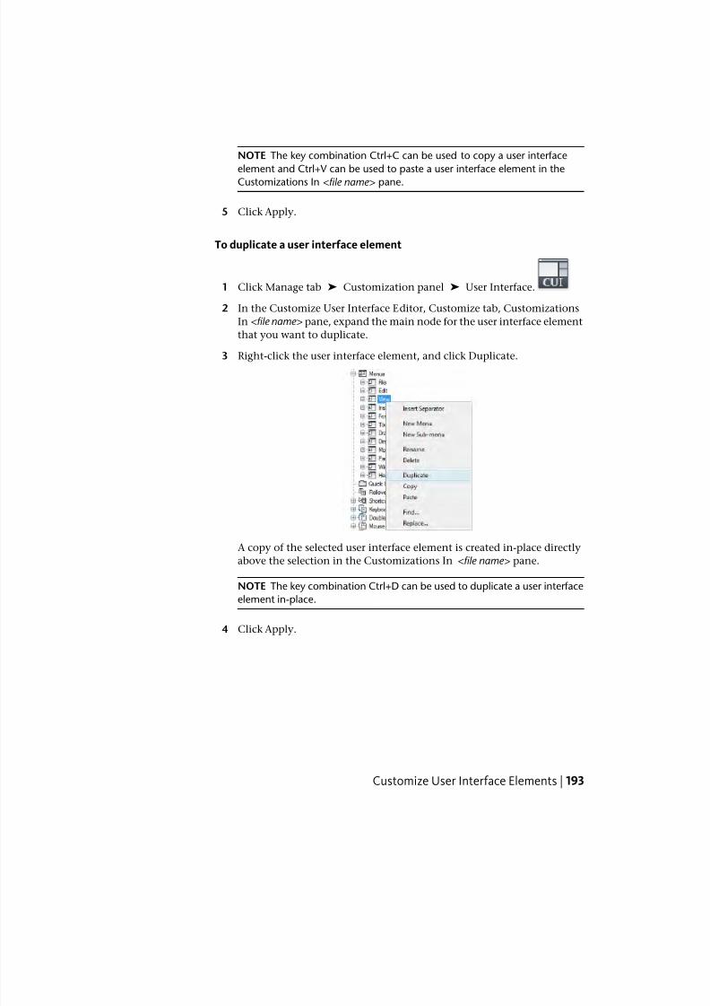
7/23/2019 Acad Customization
http://slidepdf.com/reader/full/acad-customization 201/553
NOTE The key combination Ctrl+C can be used to copy a user interface
element and Ctrl+V can be used to paste a user interface element in the
Customizations In <file name> pane.
5 Click Apply.
To duplicate a user interface element
1 Click Manage tab ➤ Customization panel ➤ User Interface.
2 In the Customize User Interface Editor, Customize tab, Customizations
In <file name> pane, expand the main node for the user interface element
that you want to duplicate.
3 Right-click the user interface element, and click Duplicate.
A copy of the selected user interface element is created in-place directly
above the selection in the Customizations In <file name> pane.
NOTE The key combination Ctrl+D can be used to duplicate a user interface
element in-place.
4 Click Apply.
Customize User Interface Elements | 193
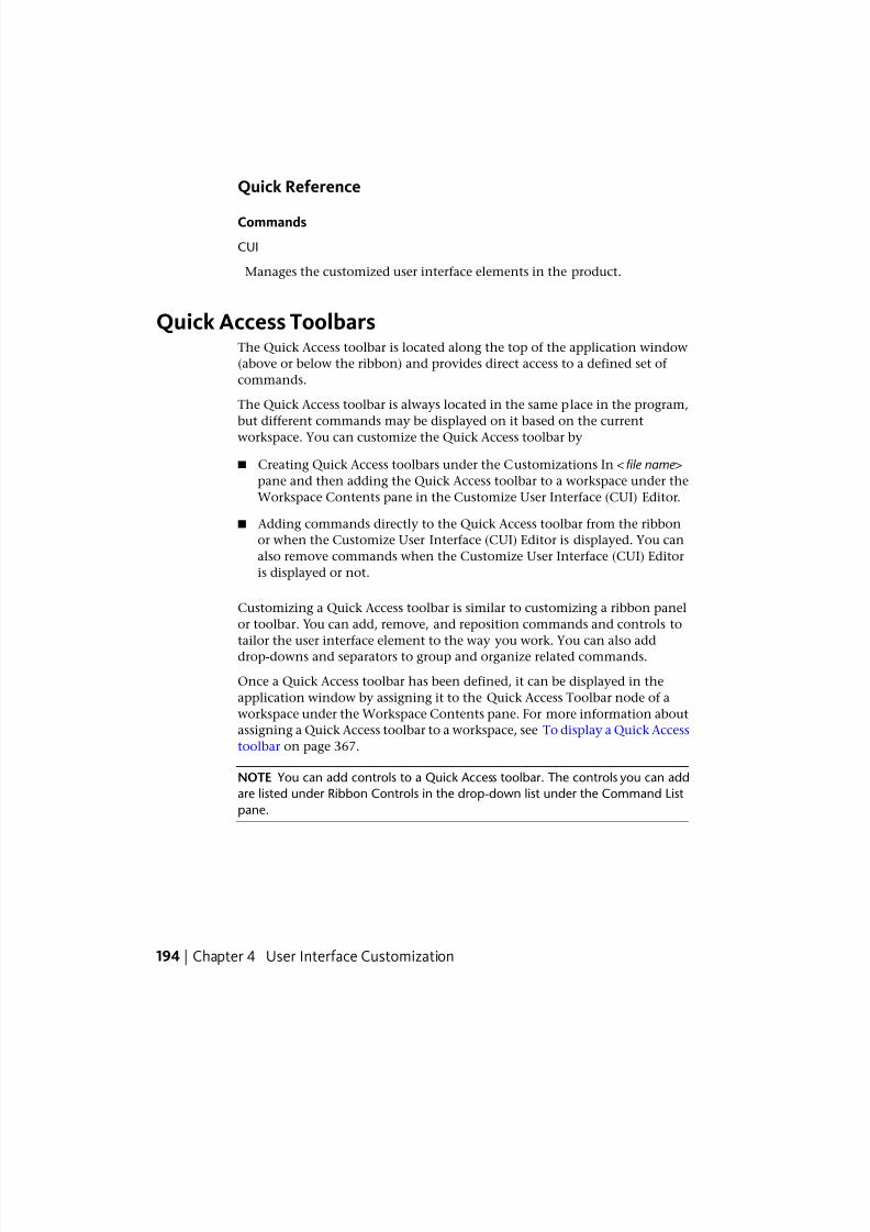
7/23/2019 Acad Customization
http://slidepdf.com/reader/full/acad-customization 202/553
Quick Reference
Commands
CUI
Manages the customized user interface elements in the product.
Quick Access ToolbarsThe Quick Access toolbar is located along the top of the application window
(above or below the ribbon) and provides direct access to a defined set of
commands.
The Quick Access toolbar is always located in the same place in the program,
but different commands may be displayed on it based on the current
workspace. You can customize the Quick Access toolbar by
■ Creating Quick Access toolbars under the Customizations In <file name >
pane and then adding the Quick Access toolbar to a workspace under the
Workspace Contents pane in the Customize User Interface (CUI) Editor.
■ Adding commands directly to the Quick Access toolbar from the ribbon
or when the Customize User Interface (CUI) Editor is displayed. You can
also remove commands when the Customize User Interface (CUI) Editor
is displayed or not.
Customizing a Quick Access toolbar is similar to customizing a ribbon panel
or toolbar. You can add, remove, and reposition commands and controls to
tailor the user interface element to the way you work. You can also adddrop-downs and separators to group and organize related commands.
Once a Quick Access toolbar has been defined, it can be displayed in the
application window by assigning it to the Quick Access Toolbar node of a
workspace under the Workspace Contents pane. For more information about
assigning a Quick Access toolbar to a workspace, see To display a Quick Access
toolbar on page 367.
NOTE You can add controls to a Quick Access toolbar. The controls you can add
are listed under Ribbon Controls in the drop-down list under the Command List
pane.
194 | Chapter 4 User Interface Customization
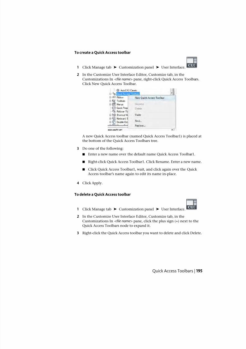
7/23/2019 Acad Customization
http://slidepdf.com/reader/full/acad-customization 203/553
To create a Quick Access toolbar
1 Click Manage tab ➤ Customization panel ➤ User Interface.
2 In the Customize User Interface Editor, Customize tab, in the
Customizations In <file name> pane, right-click Quick Access Toolbars.
Click New Quick Access Toolbar.
A new Quick Access toolbar (named Quick Access Toolbar1) is placed at
the bottom of the Quick Access Toolbars tree.
3 Do one of the following:
■ Enter a new name over the default name Quick Access Toolbar1.
■ Right-click Quick Access Toolbar1. Click Rename. Enter a new name.
■ Click Quick Access Toolbar1, wait, and click again over the Quick
Access toolbar’s name again to edit its name in-place.
4 Click Apply.
To delete a Quick Access toolbar
1 Click Manage tab ➤ Customization panel ➤ User Interface.
2 In the Customize User Interface Editor, Customize tab, in the
Customizations In <file name> pane, click the plus sign (+) next to the
Quick Access Toolbars node to expand it.
3 Right-click the Quick Access toolbar you want to delete and click Delete.
Quick Access Toolbars | 195
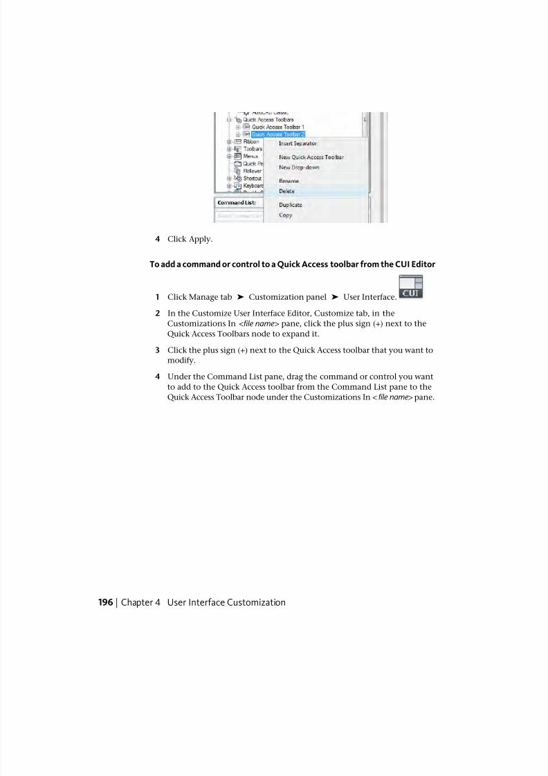
7/23/2019 Acad Customization
http://slidepdf.com/reader/full/acad-customization 204/553
4 Click Apply.
To add a command or control to a Quick Access toolbar from the CUI Editor
1 Click Manage tab ➤ Customization panel ➤ User Interface.
2 In the Customize User Interface Editor, Customize tab, in the
Customizations In <file name> pane, click the plus sign (+) next to the
Quick Access Toolbars node to expand it.
3 Click the plus sign (+) next to the Quick Access toolbar that you want to
modify.
4 Under the Command List pane, drag the command or control you want
to add to the Quick Access toolbar from the Command List pane to the
Quick Access Toolbar node under the Customizations In <file name > pane.
196 | Chapter 4 User Interface Customization
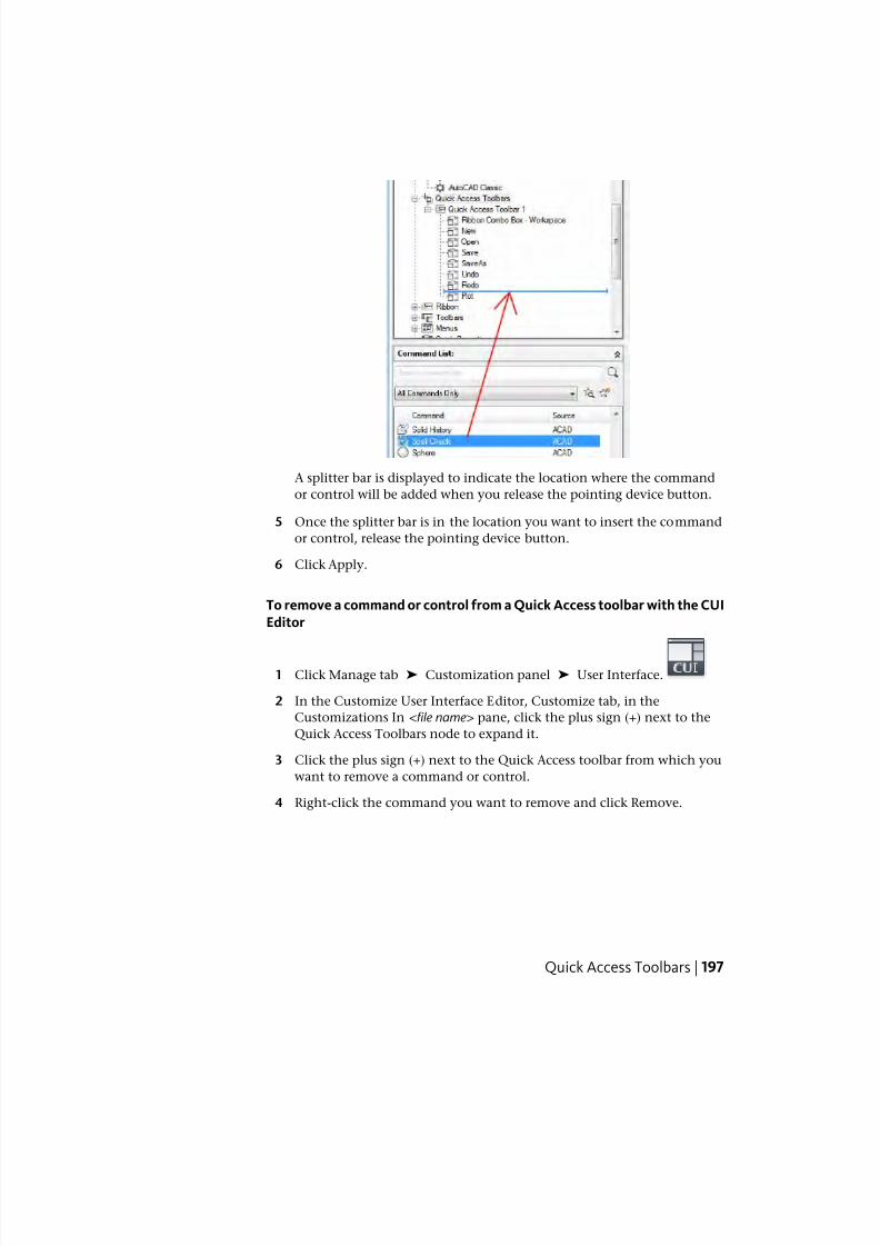
7/23/2019 Acad Customization
http://slidepdf.com/reader/full/acad-customization 205/553
A splitter bar is displayed to indicate the location where the command
or control will be added when you release the pointing device button.
5 Once the splitter bar is in the location you want to insert the command
or control, release the pointing device button.
6 Click Apply.
To remove a command or control from a Quick Access toolbar with the CUIEditor
1 Click Manage tab ➤ Customization panel ➤ User Interface.
2 In the Customize User Interface Editor, Customize tab, in the
Customizations In <file name> pane, click the plus sign (+) next to the
Quick Access Toolbars node to expand it.
3 Click the plus sign (+) next to the Quick Access toolbar from which you
want to remove a command or control.
4 Right-click the command you want to remove and click Remove.
Quick Access Toolbars | 197
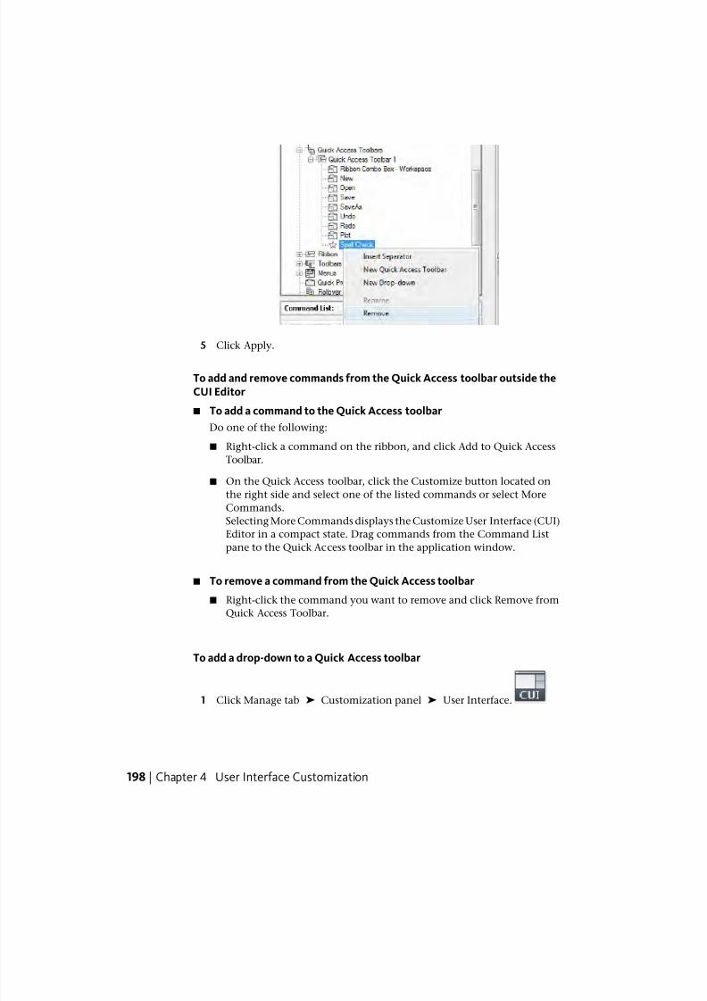
7/23/2019 Acad Customization
http://slidepdf.com/reader/full/acad-customization 206/553
5 Click Apply.
To add and remove commands from the Quick Access toolbar outside theCUI Editor
■ To add a command to the Quick Access toolbar
Do one of the following:
■ Right-click a command on the ribbon, and click Add to Quick Access
Toolbar.
■ On the Quick Access toolbar, click the Customize button located on
the right side and select one of the listed commands or select More
Commands.
Selecting More Commands displays the Customize User Interface (CUI)Editor in a compact state. Drag commands from the Command List
pane to the Quick Access toolbar in the application window.
■ To remove a command from the Quick Access toolbar
■ Right-click the command you want to remove and click Remove from
Quick Access Toolbar.
To add a drop-down to a Quick Access toolbar
1 Click Manage tab ➤ Customization panel ➤ User Interface.
198 | Chapter 4 User Interface Customization
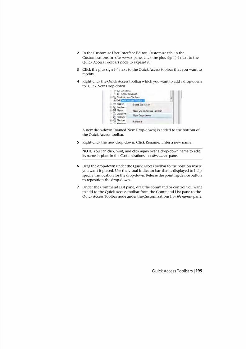
7/23/2019 Acad Customization
http://slidepdf.com/reader/full/acad-customization 207/553
2 In the Customize User Interface Editor, Customize tab, in the
Customizations In <file name> pane, click the plus sign (+) next to the
Quick Access Toolbars node to expand it.
3 Click the plus sign (+) next to the Quick Access toolbar that you want to
modify.
4 Right-click the Quick Access toolbar which you want to add a drop-down
to. Click New Drop-down.
A new drop-down (named New Drop-down) is added to the bottom of
the Quick Access toolbar.
5 Right-click the new drop-down. Click Rename. Enter a new name.
NOTE You can click, wait, and click again over a drop-down name to edit
its name in-place in the Customizations In <file name > pane.
6 Drag the drop-down under the Quick Access toolbar to the position where
you want it placed. Use the visual indicator bar that is displayed to help
specify the location for the drop-down. Release the pointing device button
to reposition the drop-down.
7 Under the Command List pane, drag the command or control you want
to add to the Quick Access toolbar from the Command List pane to the
Quick Access Toolbar node under the Customizations In <file name > pane.
Quick Access Toolbars | 199
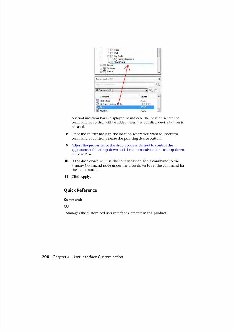
7/23/2019 Acad Customization
http://slidepdf.com/reader/full/acad-customization 208/553
A visual indicator bar is displayed to indicate the location where the
command or control will be added when the pointing device button is
released.
8 Once the splitter bar is in the location where you want to insert the
command or control, release the pointing device button.
9 Adjust the properties of the drop-down as desired to control the
appearance of the drop-down and the commands under the drop-down.
on page 216
10 If the drop-down will use the Split behavior, add a command to the
Primary Command node under the drop-down to set the command for
the main button.
11 Click Apply.
Quick Reference
Commands
CUI
Manages the customized user interface elements in the product.
200 | Chapter 4 User Interface Customization
7/23/2019 Acad Customization
http://slidepdf.com/reader/full/acad-customization 209/553
RibbonYou can customize the ribbon by creating and modifying ribbon panels andorganizing ribbon panels into groups of task-based tools with ribbon tabs.
Ribbon tabs can be displayed on the ribbon with a workspace or based on a
contextual tab state when they are needed.
Ribbon PanelsBy customizing ribbon panels, you can organize commands that you use
frequently similar to toolbars. With ribbon panels, you can quickly access
commands, and reduce the number of user interface elements that are
displayed.
Overview of Ribbon Panels
Ribbon panels are organized by rows, sub-panels, and slideout elements. Rows
and sub-panels are used to organize how commands and controls are displayed
on the ribbon panel. A slideout is automatically added to each ribbon panel
and controls which rows are shown by default. Rows located below a slideout
are displayed only when a ribbon panel is expanded.
The following table describes the properties of the Home 2D - Draw ribbon
panel as they appear in the Properties pane.
Properties for the Home 2D - Draw Ribbon Panel
ExampleDescriptionProperties
Pane Item
Home 2D - DrawName of the panel; does not appear in the user
interface.
Name
DrawTitle of the panel; displayed when the ribbon is
set to display titles or when a panel is floating.
Display
Text
Text used to describe the element; does not
appear in the user interface and is optional.
Descrip-
tion
Specifies the keytip characters that can be used
to access the ribbon panel from the keyboard.
KeyTip
Ribbon | 201
7/23/2019 Acad Customization
http://slidepdf.com/reader/full/acad-customization 210/553
Properties for the Home 2D - Draw Ribbon Panel
ExampleDescriptionPropertiesPane Item
ID_DrawSpecifies the aliases for the panel. Click the [ ]button to open the Aliases dialog box. Each
Aliases
alias in the CUIx file should be unique and is
used to reference the panel programmatically.
ID_PanelDrawTag that uniquely identifies a panel.Element ID
Create a Ribbon Panel
Ribbon panels can be created from scratch or from an existing toolbar or
dashboard panel. Create ribbon panels from scratch under the Ribbon Panels
node on the Customizations In <file name > pane of the Customize tab. Thisgives you control over which commands are displayed on the ribbon panel.
If you have an existing toolbar or dashboard panel from a previous release,
you can create a new ribbon panel from them. Copy toolbars to a ribbon panel
from the Toolbars node under the Customizations In <file name > pane on the
Customize or Transfer tabs. Dashboard panels can only be copied to ribbon
panels from the Dashboard Panels node on the Transfer tab.
Display Ribbon Panels on the Ribbon
The display of ribbon panels is controlled with ribbon tabs. Once a ribbon tab
is defined, the ribbon tab can be added to a workspace, which controls which
ribbon tabs are displayed and the order in which they are displayed on the
ribbon. For more information about ribbon tabs, see Ribbon Tabs on page 238under Customize User Interface Elements on page 191.
Associating Tool Palette Group with a Ribbon Panel
You can associate a tool palette group with a ribbon panel. By associating a
tool palette group to a ribbon panel you can quickly access additional tools
that are related to a ribbon panel and are defined on a tool palette. The
association of a tool palette group to a ribbon panel is done from the ribbon.
For more information about tool palettes and tool palette groups, see
Customize Tool Palettes and Organize Tool Palettes in the User ’ s Guide .
202 | Chapter 4 User Interface Customization

7/23/2019 Acad Customization
http://slidepdf.com/reader/full/acad-customization 211/553
To create a ribbon panel
1 Click Manage tab ➤ Customization panel ➤ User Interface.
2 In the Customize User Interface Editor, Customize tab, in the
Customizations In <file name> pane, click the plus sign (+) next to the
Ribbons node to expand it.
3 Right-click Panels. Click New Panel.
A new panel (named Panel1) is placed at the bottom of the Ribbon Panels
tree.
4 Right-click Panel1. Click Rename. Enter a new panel name.
5 Select the new panel, and update its properties in the Properties pane:
■ In the Display Text box, enter the text you want to display for the
title of the panel when it is displayed on the ribbon.
■ In the KeyTip box, enter the characters to access the ribbon panel
from the keyboard.
■
In the Aliases box, enter an alias for the ribbon panel.
6 Click Apply.
Ribbon | 203
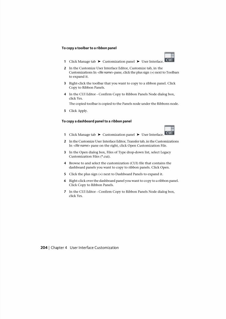
7/23/2019 Acad Customization
http://slidepdf.com/reader/full/acad-customization 212/553
To copy a toolbar to a ribbon panel
1 Click Manage tab ➤ Customization panel ➤ User Interface.
2 In the Customize User Interface Editor, Customize tab, in the
Customizations In <file name> pane, click the plus sign (+) next to Toolbars
to expand it.
3 Right-click the toolbar that you want to copy to a ribbon panel. Click
Copy to Ribbon Panels.
4 In the CUI Editor - Confirm Copy to Ribbon Panels Node dialog box,
click Yes.
The copied toolbar is copied to the Panels node under the Ribbons node.
5 Click Apply.
To copy a dashboard panel to a ribbon panel
1 Click Manage tab ➤ Customization panel ➤ User Interface.
2 In the Customize User Interface Editor, Transfer tab, in the Customizations
In <file name> pane on the right, click Open Customization File.
3 In the Open dialog box, Files of Type drop-down list, select Legacy
Customization Files (*.cui).
4 Browse to and select the customization (CUI) file that contains the
dashboard panels you want to copy to ribbon panels. Click Open.
5 Click the plus sign (+) next to Dashboard Panels to expand it.
6 Right-click over the dashboard panel you want to copy to a ribbon panel.
Click Copy to Ribbon Panels.
7 In the CUI Editor - Confirm Copy to Ribbon Panels Node dialog box,
click Yes.
204 | Chapter 4 User Interface Customization
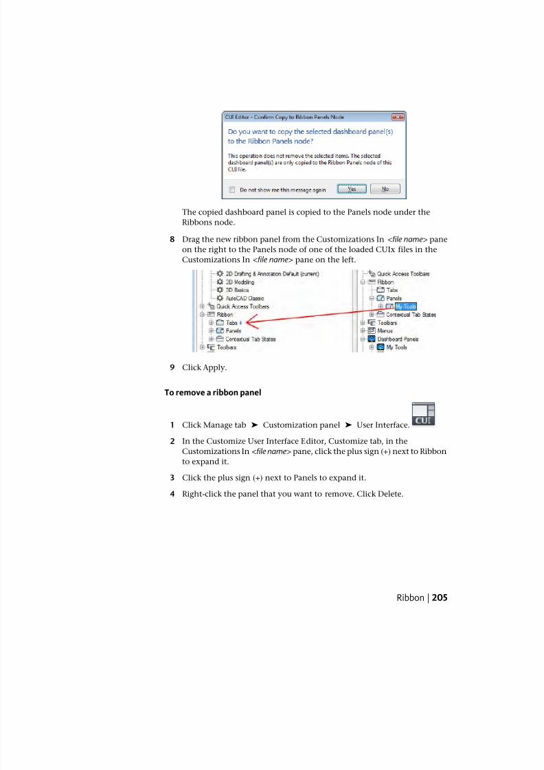
7/23/2019 Acad Customization
http://slidepdf.com/reader/full/acad-customization 213/553
The copied dashboard panel is copied to the Panels node under the
Ribbons node.
8 Drag the new ribbon panel from the Customizations In <file name> pane
on the right to the Panels node of one of the loaded CUIx files in the
Customizations In <file name> pane on the left.
9 Click Apply.
To remove a ribbon panel
1 Click Manage tab ➤ Customization panel ➤ User Interface.
2 In the Customize User Interface Editor, Customize tab, in the
Customizations In <file name> pane, click the plus sign (+) next to Ribbon
to expand it.
3 Click the plus sign (+) next to Panels to expand it.
4 Right-click the panel that you want to remove. Click Delete.
Ribbon | 205
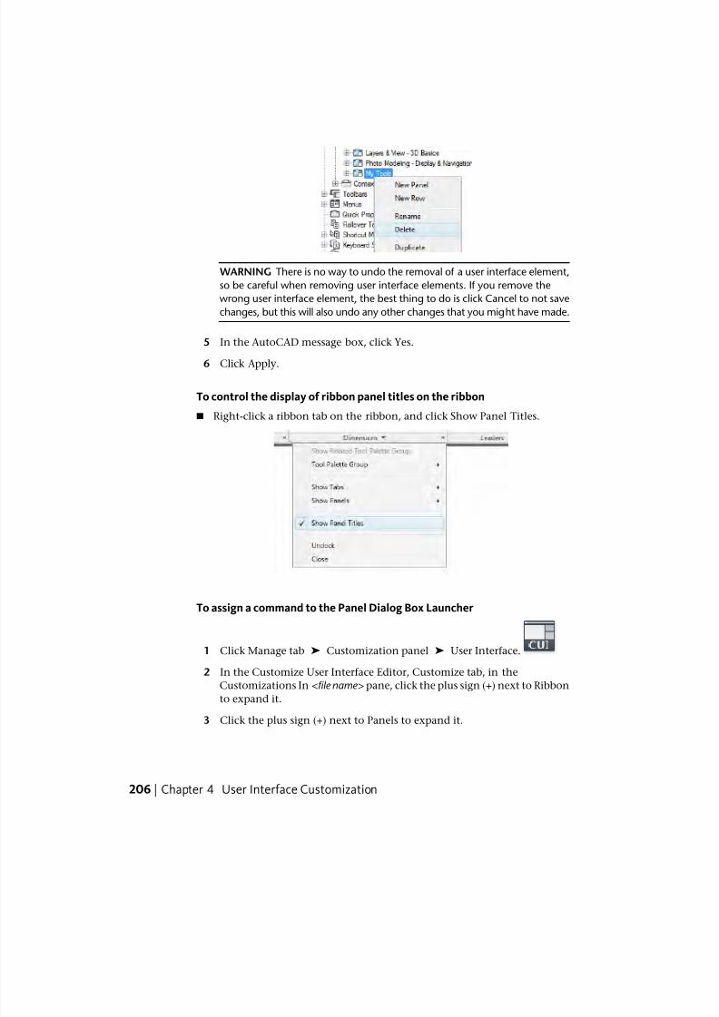
7/23/2019 Acad Customization
http://slidepdf.com/reader/full/acad-customization 214/553
WARNING There is no way to undo the removal of a user interface element,
so be careful when removing user interface elements. If you remove the
wrong user interface element, the best thing to do is click Cancel to not save
changes, but this will also undo any other changes that you might have made.
5 In the AutoCAD message box, click Yes.
6 Click Apply.
To control the display of ribbon panel titles on the ribbon
■ Right-click a ribbon tab on the ribbon, and click Show Panel Titles.
To assign a command to the Panel Dialog Box Launcher
1 Click Manage tab ➤ Customization panel ➤ User Interface.
2 In the Customize User Interface Editor, Customize tab, in the
Customizations In <file name> pane, click the plus sign (+) next to Ribbon
to expand it.
3 Click the plus sign (+) next to Panels to expand it.
206 | Chapter 4 User Interface Customization
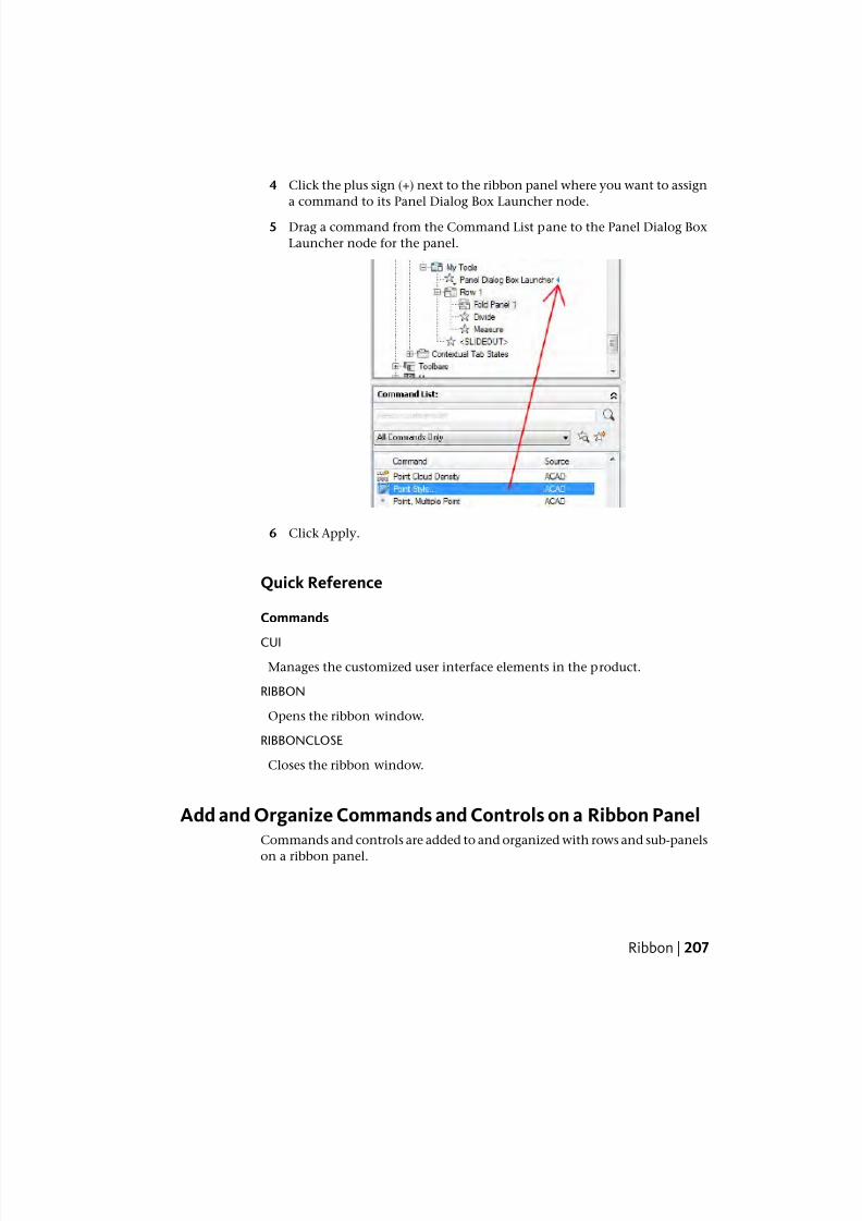
7/23/2019 Acad Customization
http://slidepdf.com/reader/full/acad-customization 215/553
4 Click the plus sign (+) next to the ribbon panel where you want to assign
a command to its Panel Dialog Box Launcher node.
5 Drag a command from the Command List pane to the Panel Dialog Box
Launcher node for the panel.
6 Click Apply.
Quick Reference
Commands
CUI
Manages the customized user interface elements in the product.
RIBBON
Opens the ribbon window.
RIBBONCLOSE
Closes the ribbon window.
Add and Organize Commands and Controls on a Ribbon PanelCommands and controls are added to and organized with rows and sub-panels
on a ribbon panel.
Ribbon | 207
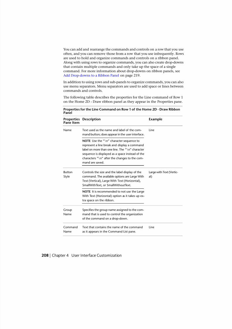
7/23/2019 Acad Customization
http://slidepdf.com/reader/full/acad-customization 216/553
You can add and rearrange the commands and controls on a row that you use
often, and you can remove those from a row that you use infrequently. Rows
are used to hold and organize commands and controls on a ribbon panel.Along with using rows to organize commands, you can also create drop-downs
that contain multiple commands and only take up the space of a single
command. For more information about drop-downs on ribbon panels, see
Add Drop-downs to a Ribbon Panel on page 219.
In addition to using rows and sub-panels to organize commands, you can also
use menu separators. Menu separators are used to add space or lines between
commands and controls.
The following table describes the properties for the Line command of Row 1
on the Home 2D - Draw ribbon panel as they appear in the Properties pane.
Properties for the Line Command on Row 1 of the Home 2D - Draw RibbonPanel
ExampleDescriptionPropertiesPane Item
LineText used as the name and label of the com-
mand button; does appear in the user interface.
Name
NOTE Use the “\n” character sequence to
represent a line break and display a command
label on more than one line. The “\n” character
sequence is displayed as a space instead of the
characters “\n” after the changes to the com-
mand are saved.
Large with Text (Vertic-al)
Controls the size and the label display of thecommand. The available options are Large With
ButtonStyle
Text (Vertical), Large With Text (Horizontal),
SmallWithText, or SmallWithoutText.
NOTE It is recommended to not use the Large
With Text (Horizontal) option as it takes up ex-
tra space on the ribbon.
Specifies the group name assigned to the com-
mand that is used to control the organization
of the command on a drop-down.
Group
Name
LineText that contains the name of the command
as it appears in the Command List pane.
Command
Name
208 | Chapter 4 User Interface Customization
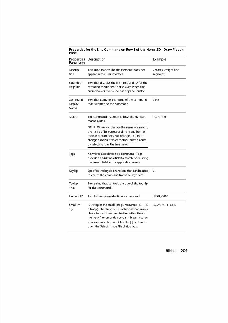
7/23/2019 Acad Customization
http://slidepdf.com/reader/full/acad-customization 217/553
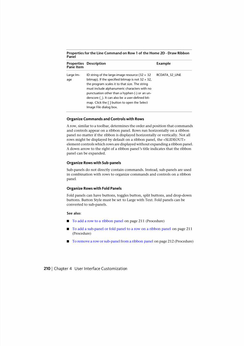
7/23/2019 Acad Customization
http://slidepdf.com/reader/full/acad-customization 218/553
Properties for the Line Command on Row 1 of the Home 2D - Draw RibbonPanel
ExampleDescriptionPropertiesPane Item
RCDATA_32_LINEID string of the large-image resource (32 × 32
bitmap). If the specified bitmap is not 32 × 32,
Large Im-
age
the program scales it to that size. The string
must include alphanumeric characters with no
punctuation other than a hyphen (-) or an un-
derscore (_). It can also be a user-defined bit-
map. Click the [ ] button to open the Select
Image File dialog box.
Organize Commands and Controls with Rows
A row, similar to a toolbar, determines the order and position that commands
and controls appear on a ribbon panel. Rows run horizontally on a ribbon
panel no matter if the ribbon is displayed horizontally or vertically. Not all
rows might be displayed by default on a ribbon panel, the <SLIDEOUT>
element controls which rows are displayed without expanding a ribbon panel.
A down arrow to the right of a ribbon panel’s title indicates that the ribbon
panel can be expanded.
Organize Rows with Sub-panels
Sub-panels do not directly contain commands. Instead, sub-panels are used
in combination with rows to organize commands and controls on a ribbon
panel.
Organize Rows with Fold Panels
Fold panels can have buttons, toggles button, split buttons, and drop-down
buttons. Button Style must be set to Large with Text. Fold panels can be
converted to sub-panels.
See also:
■ To add a row to a ribbon panel on page 211 (Procedure)
■ To add a sub-panel or fold panel to a row on a ribbon panel on page 211
(Procedure)
■To remove a row or sub-panel from a ribbon panel on page 212 (Procedure)
210 | Chapter 4 User Interface Customization
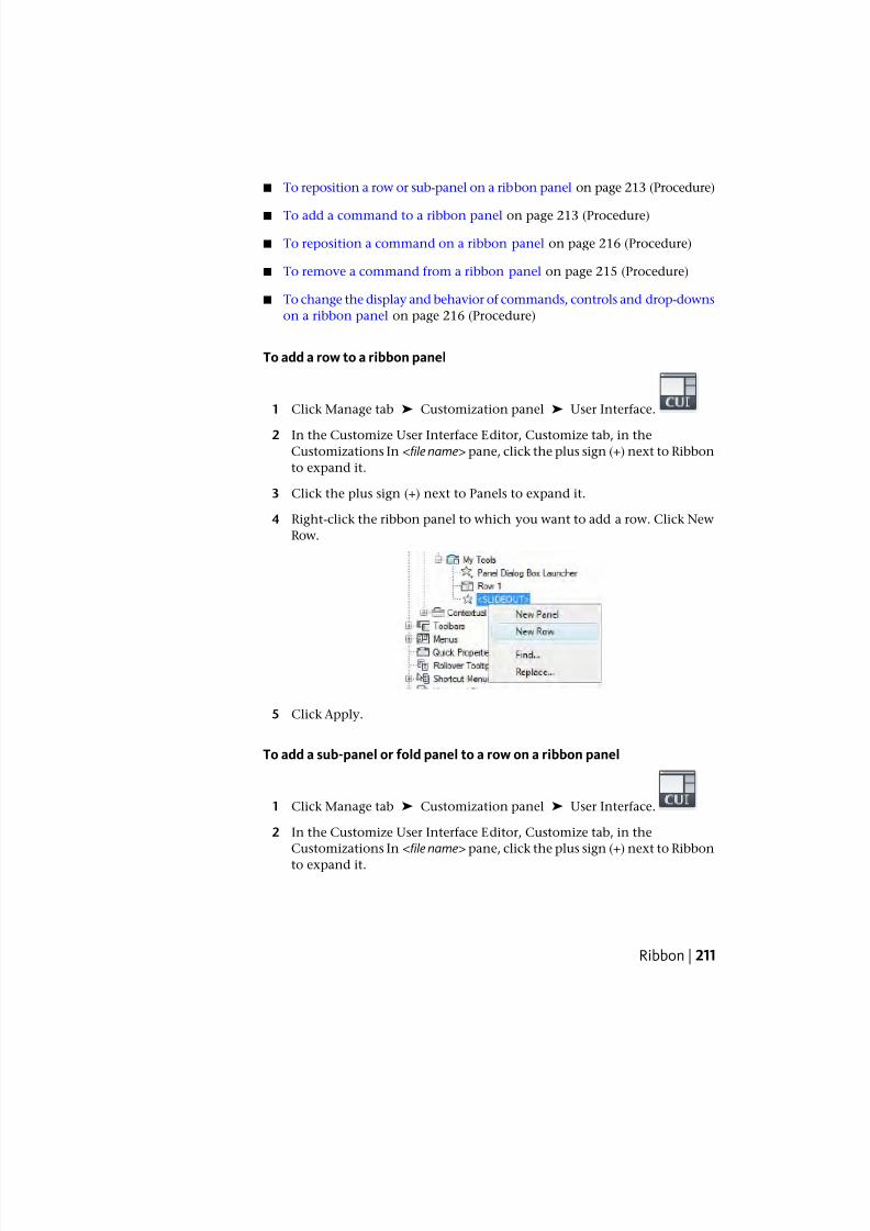
7/23/2019 Acad Customization
http://slidepdf.com/reader/full/acad-customization 219/553
■ To reposition a row or sub-panel on a ribbon panel on page 213 (Procedure)
■ To add a command to a ribbon panel on page 213 (Procedure)
■ To reposition a command on a ribbon panel on page 216 (Procedure)
■ To remove a command from a ribbon panel on page 215 (Procedure)
■ To change the display and behavior of commands, controls and drop-downs
on a ribbon panel on page 216 (Procedure)
To add a row to a ribbon panel
1 Click Manage tab ➤ Customization panel ➤ User Interface.
2 In the Customize User Interface Editor, Customize tab, in theCustomizations In <file name> pane, click the plus sign (+) next to Ribbon
to expand it.
3 Click the plus sign (+) next to Panels to expand it.
4 Right-click the ribbon panel to which you want to add a row. Click New
Row.
5 Click Apply.
To add a sub-panel or fold panel to a row on a ribbon panel
1 Click Manage tab ➤ Customization panel ➤ User Interface.
2 In the Customize User Interface Editor, Customize tab, in the
Customizations In <file name> pane, click the plus sign (+) next to Ribbon
to expand it.
Ribbon | 211
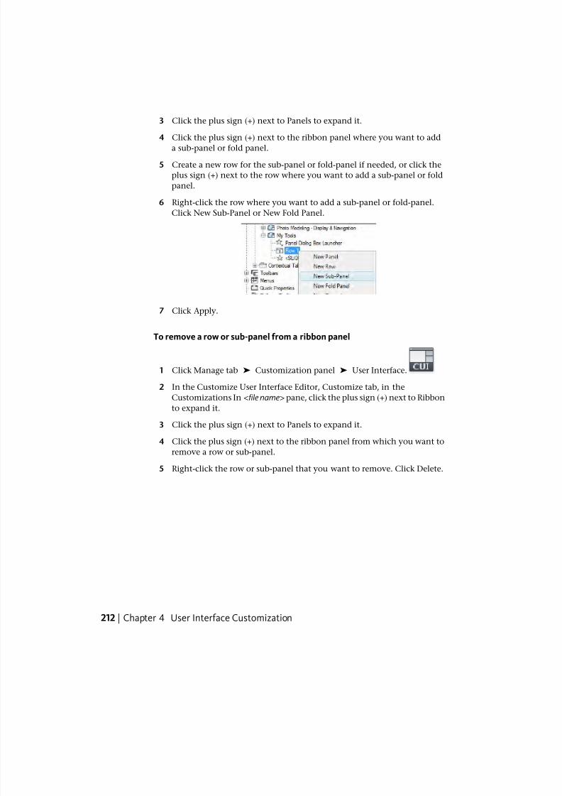
7/23/2019 Acad Customization
http://slidepdf.com/reader/full/acad-customization 220/553
3 Click the plus sign (+) next to Panels to expand it.
4 Click the plus sign (+) next to the ribbon panel where you want to adda sub-panel or fold panel.
5 Create a new row for the sub-panel or fold-panel if needed, or click the
plus sign (+) next to the row where you want to add a sub-panel or fold
panel.
6 Right-click the row where you want to add a sub-panel or fold-panel.
Click New Sub-Panel or New Fold Panel.
7 Click Apply.
To remove a row or sub-panel from a ribbon panel
1 Click Manage tab ➤ Customization panel ➤ User Interface.
2 In the Customize User Interface Editor, Customize tab, in the
Customizations In <file name> pane, click the plus sign (+) next to Ribbon
to expand it.
3 Click the plus sign (+) next to Panels to expand it.
4 Click the plus sign (+) next to the ribbon panel from which you want to
remove a row or sub-panel.
5 Right-click the row or sub-panel that you want to remove. Click Delete.
212 | Chapter 4 User Interface Customization
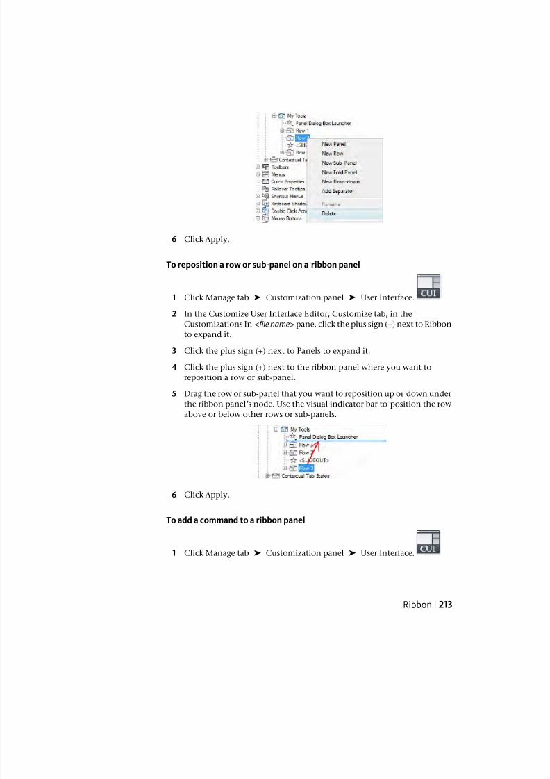
7/23/2019 Acad Customization
http://slidepdf.com/reader/full/acad-customization 221/553
6 Click Apply.
To reposition a row or sub-panel on a ribbon panel
1 Click Manage tab ➤ Customization panel ➤ User Interface.
2 In the Customize User Interface Editor, Customize tab, in the
Customizations In <file name> pane, click the plus sign (+) next to Ribbon
to expand it.
3 Click the plus sign (+) next to Panels to expand it.
4 Click the plus sign (+) next to the ribbon panel where you want to
reposition a row or sub-panel.
5 Drag the row or sub-panel that you want to reposition up or down under
the ribbon panel’s node. Use the visual indicator bar to position the row
above or below other rows or sub-panels.
6 Click Apply.
To add a command to a ribbon panel
1 Click Manage tab ➤ Customization panel ➤ User Interface.
Ribbon | 213
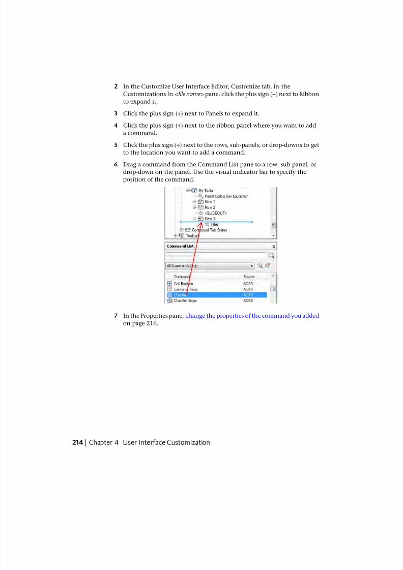
7/23/2019 Acad Customization
http://slidepdf.com/reader/full/acad-customization 222/553
2 In the Customize User Interface Editor, Customize tab, in the
Customizations In <file name> pane, click the plus sign (+) next to Ribbon
to expand it.
3 Click the plus sign (+) next to Panels to expand it.
4 Click the plus sign (+) next to the ribbon panel where you want to add
a command.
5 Click the plus sign (+) next to the rows, sub-panels, or drop-downs to get
to the location you want to add a command.
6 Drag a command from the Command List pane to a row, sub-panel, or
drop-down on the panel. Use the visual indicator bar to specify the
position of the command.
7 In the Properties pane, change the properties of the command you added
on page 216.
214 | Chapter 4 User Interface Customization
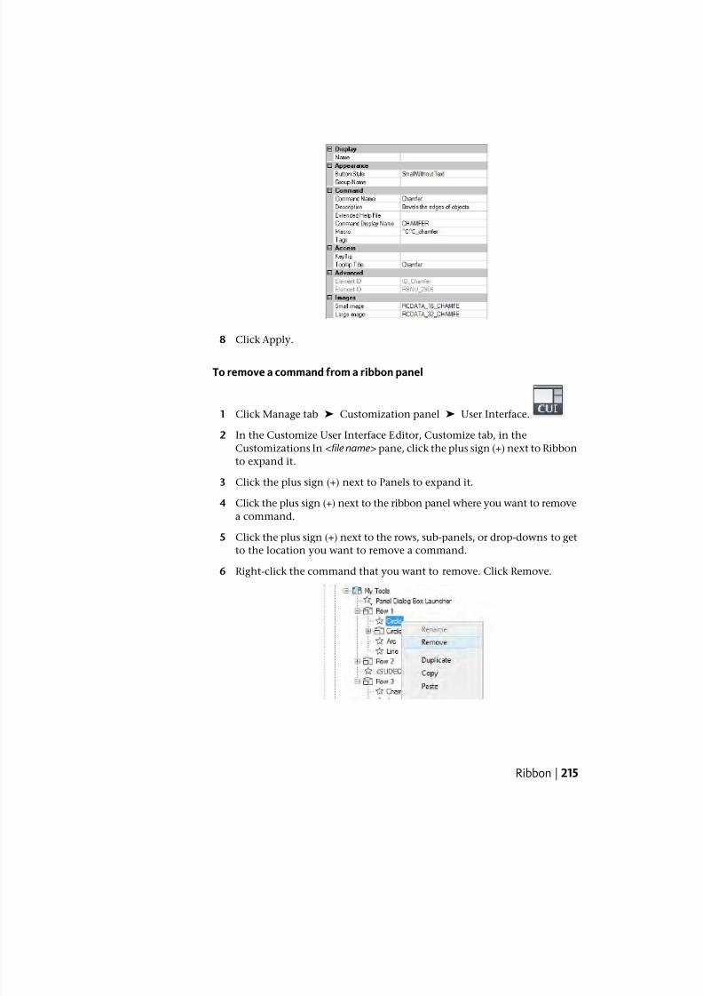
7/23/2019 Acad Customization
http://slidepdf.com/reader/full/acad-customization 223/553
8 Click Apply.
To remove a command from a ribbon panel
1 Click Manage tab ➤ Customization panel ➤ User Interface.
2 In the Customize User Interface Editor, Customize tab, in the
Customizations In <file name> pane, click the plus sign (+) next to Ribbon
to expand it.
3 Click the plus sign (+) next to Panels to expand it.
4 Click the plus sign (+) next to the ribbon panel where you want to remove
a command.
5 Click the plus sign (+) next to the rows, sub-panels, or drop-downs to get
to the location you want to remove a command.
6 Right-click the command that you want to remove. Click Remove.
Ribbon | 215
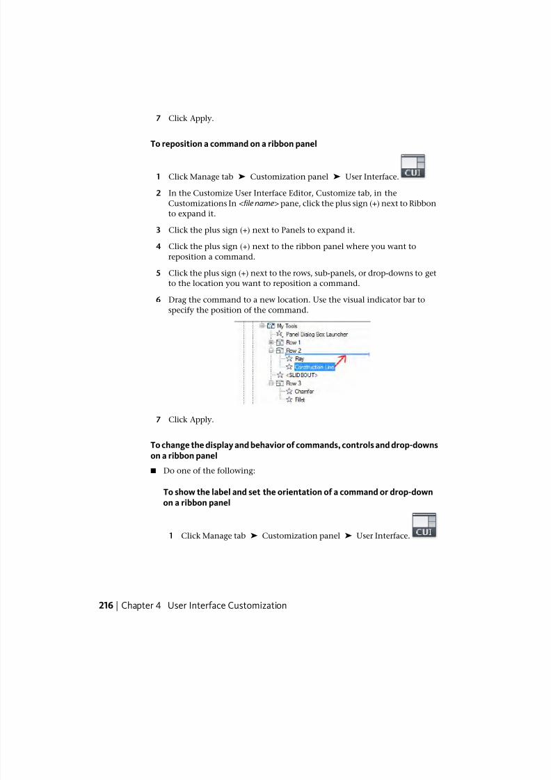
7/23/2019 Acad Customization
http://slidepdf.com/reader/full/acad-customization 224/553
7 Click Apply.
To reposition a command on a ribbon panel
1 Click Manage tab ➤ Customization panel ➤ User Interface.
2 In the Customize User Interface Editor, Customize tab, in the
Customizations In <file name> pane, click the plus sign (+) next to Ribbon
to expand it.
3 Click the plus sign (+) next to Panels to expand it.
4 Click the plus sign (+) next to the ribbon panel where you want to
reposition a command.
5 Click the plus sign (+) next to the rows, sub-panels, or drop-downs to getto the location you want to reposition a command.
6 Drag the command to a new location. Use the visual indicator bar to
specify the position of the command.
7 Click Apply.
To change the display and behavior of commands, controls and drop-downson a ribbon panel
■ Do one of the following:
To show the label and set the orientation of a command or drop-downon a ribbon panel
1 Click Manage tab ➤ Customization panel ➤ User Interface.
216 | Chapter 4 User Interface Customization
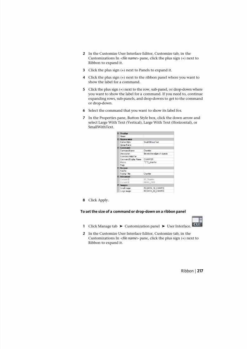
7/23/2019 Acad Customization
http://slidepdf.com/reader/full/acad-customization 225/553
2 In the Customize User Interface Editor, Customize tab, in the
Customizations In <file name> pane, click the plus sign (+) next to
Ribbon to expand it.
3 Click the plus sign (+) next to Panels to expand it.
4 Click the plus sign (+) next to the ribbon panel where you want to
show the label for a command.
5 Click the plus sign (+) next to the row, sub-panel, or drop-down where
you want to show the label for a command. If you need to, continue
expanding rows, sub-panels, and drop-downs to get to the command
or drop-down.
6 Select the command that you want to show its label for.
7 In the Properties pane, Button Style box, click the down arrow and
select Large With Text (Vertical), Large With Text (Horizontal), orSmallWithText.
8 Click Apply.
To set the size of a command or drop-down on a ribbon panel
1 Click Manage tab ➤ Customization panel ➤ User Interface.
2 In the Customize User Interface Editor, Customize tab, in the
Customizations In <file name> pane, click the plus sign (+) next to
Ribbon to expand it.
Ribbon | 217
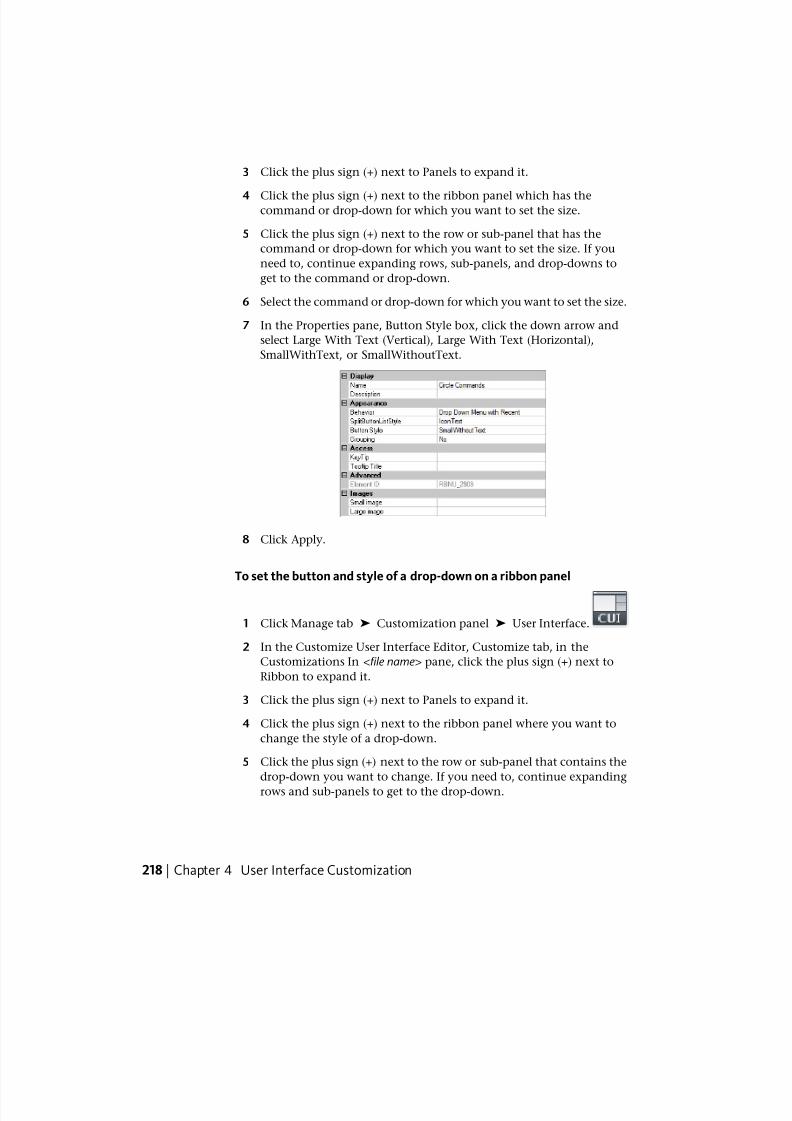
7/23/2019 Acad Customization
http://slidepdf.com/reader/full/acad-customization 226/553
3 Click the plus sign (+) next to Panels to expand it.
4 Click the plus sign (+) next to the ribbon panel which has thecommand or drop-down for which you want to set the size.
5 Click the plus sign (+) next to the row or sub-panel that has the
command or drop-down for which you want to set the size. If you
need to, continue expanding rows, sub-panels, and drop-downs to
get to the command or drop-down.
6 Select the command or drop-down for which you want to set the size.
7 In the Properties pane, Button Style box, click the down arrow and
select Large With Text (Vertical), Large With Text (Horizontal),
SmallWithText, or SmallWithoutText.
8 Click Apply.
To set the button and style of a drop-down on a ribbon panel
1 Click Manage tab ➤ Customization panel ➤ User Interface.
2 In the Customize User Interface Editor, Customize tab, in the
Customizations In <file name> pane, click the plus sign (+) next to
Ribbon to expand it.
3 Click the plus sign (+) next to Panels to expand it.
4 Click the plus sign (+) next to the ribbon panel where you want to
change the style of a drop-down.
5 Click the plus sign (+) next to the row or sub-panel that contains the
drop-down you want to change. If you need to, continue expanding
rows and sub-panels to get to the drop-down.
218 | Chapter 4 User Interface Customization
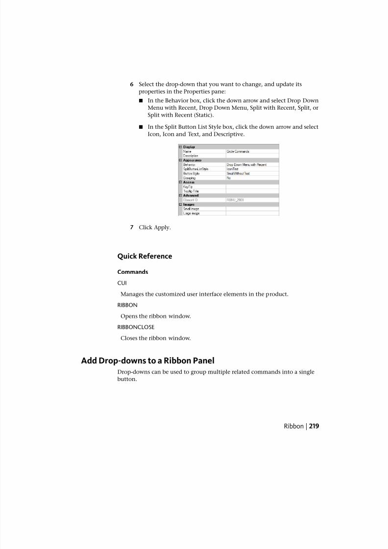
7/23/2019 Acad Customization
http://slidepdf.com/reader/full/acad-customization 227/553
6 Select the drop-down that you want to change, and update its
properties in the Properties pane:
■ In the Behavior box, click the down arrow and select Drop Down
Menu with Recent, Drop Down Menu, Split with Recent, Split, or
Split with Recent (Static).
■ In the Split Button List Style box, click the down arrow and select
Icon, Icon and Text, and Descriptive.
7 Click Apply.
Quick Reference
Commands
CUI
Manages the customized user interface elements in the product.
RIBBON
Opens the ribbon window.
RIBBONCLOSE
Closes the ribbon window.
Add Drop-downs to a Ribbon PanelDrop-downs can be used to group multiple related commands into a single
button.
Ribbon | 219
7/23/2019 Acad Customization
http://slidepdf.com/reader/full/acad-customization 228/553
Ribbon panel drop-downs, like toolbar flyouts, that can hold a number of
commands in a single place on a ribbon panel. Drop-downs are used to help
reduce the amount of space that related commands can take up. Commandson a drop-down can be started by clicking the main button or selecting a
command from the menu when the main or split button is clicked based on
how the properties of a drop-down are configured. When a drop-down is set
as a split button, the main button can reflect the most recently used command
or not, or display the image of the most recently used command with a static
label.
The following table describes the properties for the Arc drop-down of Row 1
on under Sub-Panel 1 of the Home 2D - Draw ribbon panel as they appear in
the Properties pane.
Properties for the Arc Drop-down on Row 1 of the Home 2D - Draw Ribbon Panel
ExampleDescriptionProperties Pane Item
ArcLogical name for the drop-down; does not appear
in the user interface.
Name
NOTE The “\n” character sequence represents a
line break in a command label, which is used to al-
low a command label to be displayed on more than
one line. Once focus from the Name field is lost,
the “\n” character sequence is displayed as a space
instead of the characters “\n”.
Text used to describe the element; does not appear
in the user interface.
Description
Split with RecentSpecifies if the button executes a command or dis-
plays a list of commands. The available options are
Behavior
Drop Down Menu with Recent, Drop Down Menu,
Split with Recent, Split, Split with Recent (Static).
IconTextSpecifies how the commands on the drop-down
will be displayed. The available options are Icon,
IconText, or Descriptive.
Split Button List Style
Large with Text (Vertic-
al)
Controls the size and the label display of the drop-
down. The available options are Large With Text
Button Style
(Vertical), Large With Text (Horizontal), SmallWith-
Text, or SmallWithoutText.
220 | Chapter 4 User Interface Customization
7/23/2019 Acad Customization
http://slidepdf.com/reader/full/acad-customization 229/553
Properties for the Arc Drop-down on Row 1 of the Home 2D - Draw Ribbon Panel
ExampleDescriptionProperties Pane Item
NOTE It is recommended to not use the Large With
Text (Horizontal) option as it takes up extra space
on the ribbon.
NoControls whether the commands assigned to a
drop-down are grouped based on the values as-
signed to their Group Name properties.
Grouping
ARSpecifies the keytip characters that can be used to
access the command from the keyboard.
KeyTip
Text string that controls the title of the tooltip for
the command.
Tooltip Title
ID_RBN_SPLIT-
BTN_ARC
Tag that uniquely identifies a panel section.Element ID
RCDATA_16_ARC3PTID string of the small-image resource (16 × 16 bit-
map). The string must include alphanumeric char-
Small Image
acters with no punctuation other than a hyphen (-
) or an underscore (_). It can also be a user-defined
bitmap. Click the [ ] button to open the Select Im-
age File dialog box.
RCDATA_16_ARC3PTID string of the large-image resource (32 × 32 bit-
map). If the specified bitmap is not 32 × 32, the
Large Image
program scales it to that size. The string must in-
clude alphanumeric characters with no punctuation
other than a hyphen (-) or an underscore (_). It can
also be a user-defined bitmap. Click the [ ] button
to open the Select Image File dialog box.
See also:
■
Ribbon | 221
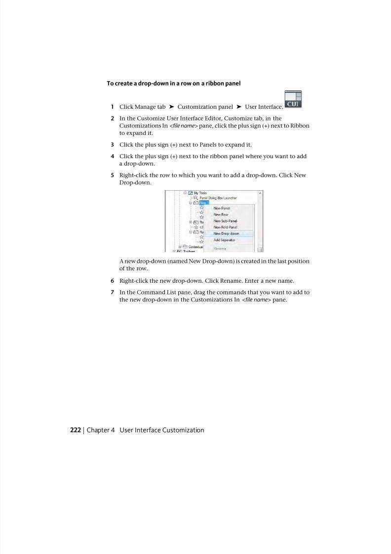
7/23/2019 Acad Customization
http://slidepdf.com/reader/full/acad-customization 230/553
To create a drop-down in a row on a ribbon panel
1 Click Manage tab ➤ Customization panel ➤ User Interface.
2 In the Customize User Interface Editor, Customize tab, in the
Customizations In <file name> pane, click the plus sign (+) next to Ribbon
to expand it.
3 Click the plus sign (+) next to Panels to expand it.
4 Click the plus sign (+) next to the ribbon panel where you want to add
a drop-down.
5 Right-click the row to which you want to add a drop-down. Click New
Drop-down.
A new drop-down (named New Drop-down) is created in the last position
of the row.
6 Right-click the new drop-down. Click Rename. Enter a new name.
7 In the Command List pane, drag the commands that you want to add tothe new drop-down in the Customizations In <file name> pane.
222 | Chapter 4 User Interface Customization
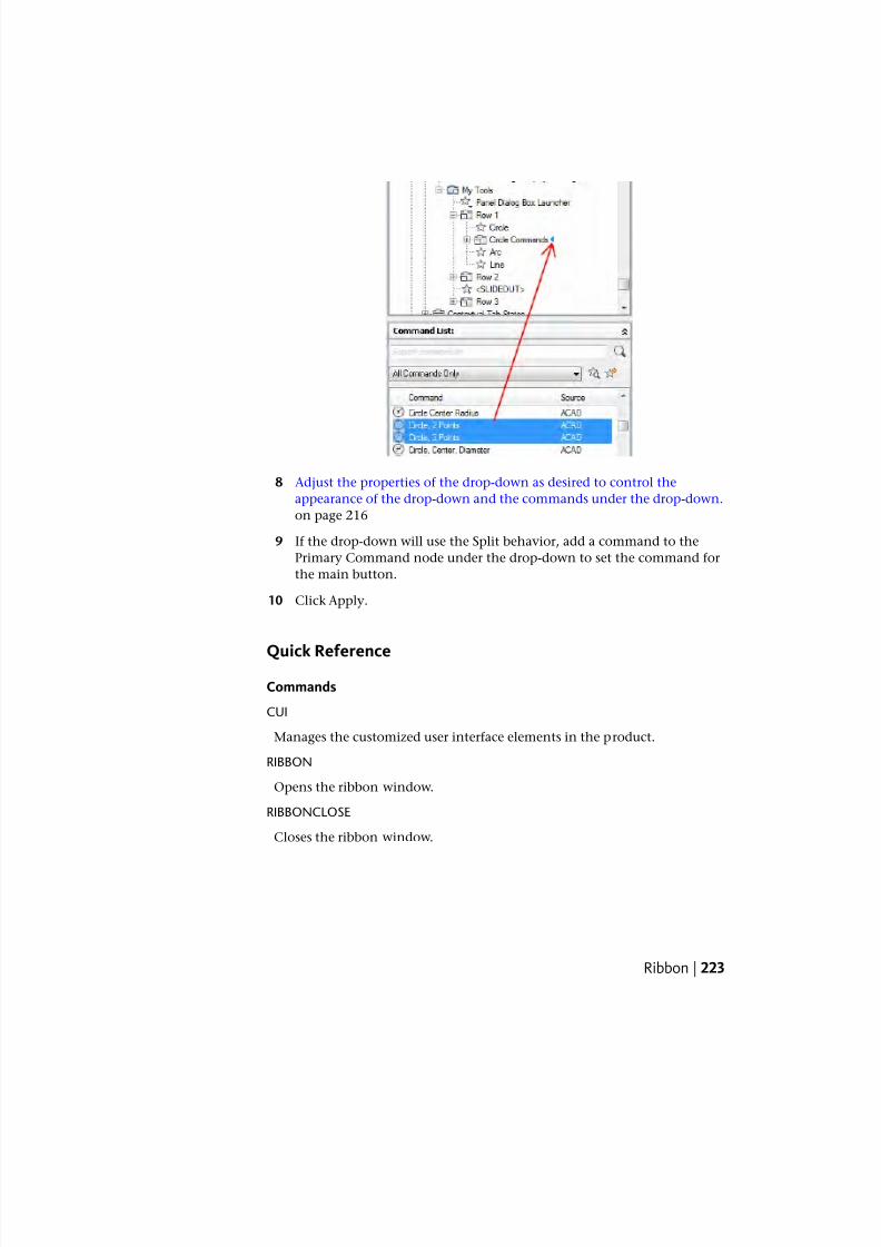
7/23/2019 Acad Customization
http://slidepdf.com/reader/full/acad-customization 231/553
8 Adjust the properties of the drop-down as desired to control the
appearance of the drop-down and the commands under the drop-down.
on page 216
9 If the drop-down will use the Split behavior, add a command to the
Primary Command node under the drop-down to set the command for
the main button.
10 Click Apply.
Quick Reference
Commands
CUI
Manages the customized user interface elements in the product.
RIBBON
Opens the ribbon window.
RIBBONCLOSE
Closes the ribbon window.
Ribbon | 223
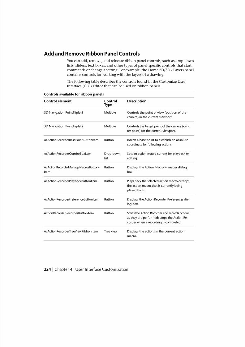
7/23/2019 Acad Customization
http://slidepdf.com/reader/full/acad-customization 232/553
Add and Remove Ribbon Panel Controls
You can add, remove, and relocate ribbon panel controls, such as drop-downlists, sliders, text boxes, and other types of panel-specific controls that start
commands or change a setting. For example, the Home 2D/3D - Layers panel
contains controls for working with the layers of a drawing.
The following table describes the controls found in the Customize User
Interface (CUI) Editor that can be used on ribbon panels.
Controls available for ribbon panels
DescriptionControlType
Control element
Controls the point of view (position of the
camera) in the current viewport.
Multiple3D Navigation PointTriplet1
Controls the target point of the camera (cen-
ter point) for the current viewport.
Multiple3D Navigation PointTriplet2
Inserts a base point to establish an absolute
coordinate for following actions.
Button AcActionRecorderBasePointButtonItem
Sets an action macro current for playback or
editing.
Drop-down
list
AcActionRecorderComboBoxItem
Displays the Action Macro Manager dialog
box.
Button AcActionRecorderManageMacrosButton-
Item
Plays back the selected action macro or stopsthe action macro that is currently being
played back.
Button AcActionRecorderPlaybackButtonItem
Displays the Action Recorder Preferences dia-
log box.
Button AcActionRecorderPreferenceButtonItem
Starts the Action Recorder and records actions
as they are performed; stops the Action Re-
corder when a recording is completed.
Button ActionRecorderRecorderButtonItem
Displays the actions in the current action
macro.
Tree view AcActionRecorderTreeViewRibbonItem
224 | Chapter 4 User Interface Customization
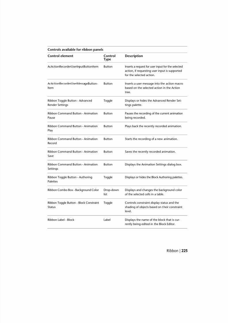
7/23/2019 Acad Customization
http://slidepdf.com/reader/full/acad-customization 233/553
Controls available for ribbon panels
DescriptionControlTypeControl element
Inserts a request for user input for the selected
action, if requesting user input is supported
for the selected action.
Button AcActionRecorderUserInputButtonItem
Inserts a user message into the action macro
based on the selected action in the Action
tree.
Button AcActionRecorderUserMessageButton-
Item
Displays or hides the Advanced Render Set-
tings palette.
ToggleRibbon Toggle Button - Advanced
Render Settings
Pauses the recording of the current animationbeing recorded.
ButtonRibbon Command Button - AnimationPause
Plays back the recently recorded animation.ButtonRibbon Command Button - Animation
Play
Starts the recording of a new animation.ButtonRibbon Command Button - Animation
Record
Saves the recently recorded animation.ButtonRibbon Command Button - Animation
Save
Displays the Animation Settings dialog box.ButtonRibbon Command Button - Animation
Settings
Displays or hides the Block Authoring palettes.ToggleRibbon Toggle Button - Authoring
Palettes
Displays and changes the background color
of the selected cells in a table.
Drop-down
list
Ribbon Combo Box - Background Color
Controls constraint display status and the
shading of objects based on their constraint
level.
ToggleRibbon Toggle Button - Block Constraint
Status
Displays the name of the block that is cur-
rently being edited in the Block Editor.
LabelRibbon Label - Block
Ribbon | 225
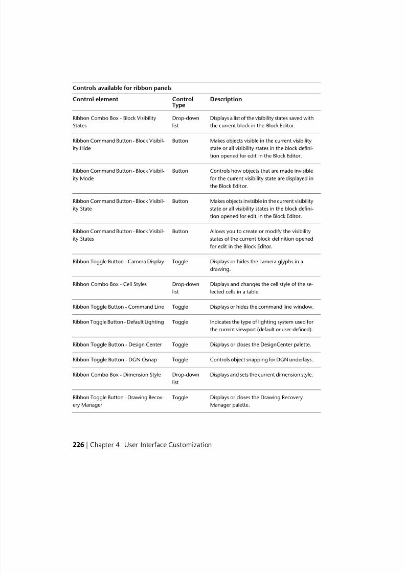
7/23/2019 Acad Customization
http://slidepdf.com/reader/full/acad-customization 234/553
Controls available for ribbon panels
DescriptionControlTypeControl element
Displays a list of the visibility states saved with
the current block in the Block Editor.
Drop-down
list
Ribbon Combo Box - Block Visibility
States
Makes objects visible in the current visibility
state or all visibility states in the block defini-
tion opened for edit in the Block Editor.
ButtonRibbon Command Button - Block Visibil-
ity Hide
Controls how objects that are made invisible
for the current visibility state are displayed in
the Block Editor.
ButtonRibbon Command Button - Block Visibil-
ity Mode
Makes objects invisible in the current visibilitystate or all visibility states in the block defini-
tion opened for edit in the Block Editor.
ButtonRibbon Command Button - Block Visibil-ity State
Allows you to create or modify the visibility
states of the current block definition opened
for edit in the Block Editor.
ButtonRibbon Command Button - Block Visibil-
ity States
Displays or hides the camera glyphs in a
drawing.
ToggleRibbon Toggle Button - Camera Display
Displays and changes the cell style of the se-
lected cells in a table.
Drop-down
list
Ribbon Combo Box - Cell Styles
Displays or hides the command line window.ToggleRibbon Toggle Button - Command Line
Indicates the type of lighting system used for
the current viewport (default or user-defined).
ToggleRibbon Toggle Button - Default Lighting
Displays or closes the DesignCenter palette.ToggleRibbon Toggle Button - Design Center
Controls object snapping for DGN underlays.ToggleRibbon Toggle Button - DGN Osnap
Displays and sets the current dimension style.Drop-down
list
Ribbon Combo Box - Dimension Style
Displays or closes the Drawing Recovery
Manager palette.
ToggleRibbon Toggle Button - Drawing Recov-
ery Manager
226 | Chapter 4 User Interface Customization
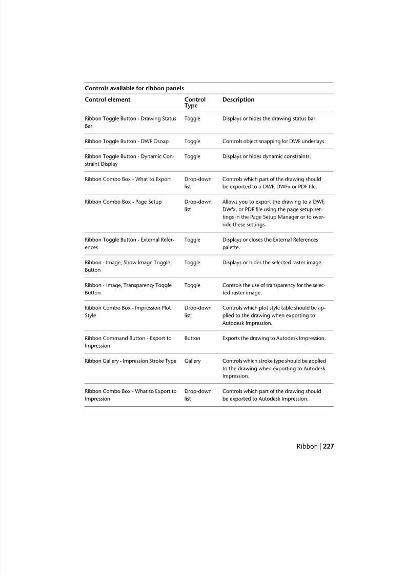
7/23/2019 Acad Customization
http://slidepdf.com/reader/full/acad-customization 235/553
Controls available for ribbon panels
DescriptionControlTypeControl element
Displays or hides the drawing status bar.ToggleRibbon Toggle Button - Drawing Status
Bar
Controls object snapping for DWF underlays.ToggleRibbon Toggle Button - DWF Osnap
Displays or hides dynamic constraints.ToggleRibbon Toggle Button - Dynamic Con-
straint Display
Controls which part of the drawing should
be exported to a DWF, DWFx or PDF file.
Drop-down
list
Ribbon Combo Box - What to Export
Allows you to export the drawing to a DWF,DWfx, or PDF file using the page setup set-
Drop-downlist
Ribbon Combo Box - Page Setup
tings in the Page Setup Manager or to over-
ride these settings.
Displays or closes the External References
palette.
ToggleRibbon Toggle Button - External Refer-
ences
Displays or hides the selected raster image.ToggleRibbon - Image, Show Image Toggle
Button
Controls the use of transparency for the selec-
ted raster image.
ToggleRibbon - Image, Transparency Toggle
Button
Controls which plot style table should be ap-
plied to the drawing when exporting to
Autodesk Impression.
Drop-down
list
Ribbon Combo Box - Impression Plot
Style
Exports the drawing to Autodesk Impression.ButtonRibbon Command Button - Export to
Impression
Controls which stroke type should be applied
to the drawing when exporting to Autodesk
Impression.
GalleryRibbon Gallery - Impression Stroke Type
Controls which part of the drawing should
be exported to Autodesk Impression.
Drop-down
list
Ribbon Combo Box - What to Export to
Impression
Ribbon | 227
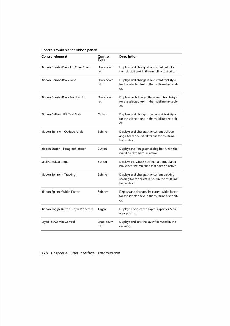
7/23/2019 Acad Customization
http://slidepdf.com/reader/full/acad-customization 236/553
Controls available for ribbon panels
DescriptionControlTypeControl element
Displays and changes the current color for
the selected text in the multiline text editor.
Drop-down
list
Ribbon Combo Box - IPE Color Color
Displays and changes the current font style
for the selected text in the multiline text edit-
or.
Drop-down
list
Ribbon Combo Box - Font
Displays and changes the current text height
for the selected text in the multiline text edit-
or.
Drop-down
list
Ribbon Combo Box - Text Height
Displays and changes the current text style for the selected text in the multiline text edit-
or.
GalleryRibbon Gallery - IPE Text Style
Displays and changes the current oblique
angle for the selected text in the multiline
text editor.
Spinner Ribbon Spinner - Oblique Angle
Displays the Paragraph dialog box when the
multiline text editor is active.
ButtonRibbon Button - Paragraph Button
Displays the Check Spelling Settings dialog
box when the multiline text editor is active.
ButtonSpell Check Settings
Displays and changes the current tracking
spacing for the selected text in the multiline
text editor.
Spinner Ribbon Spinner - Tracking
Displays and changes the current width factor
for the selected text in the multiline text edit-
or.
Spinner Ribbon Spinner Width Factor
Displays or closes the Layer Properties Man-
ager palette.
ToggleRibbon Toggle Button - Layer Properties
Displays and sets the layer filter used in the
drawing.
Drop-down
list
LayerFilterComboControl
228 | Chapter 4 User Interface Customization
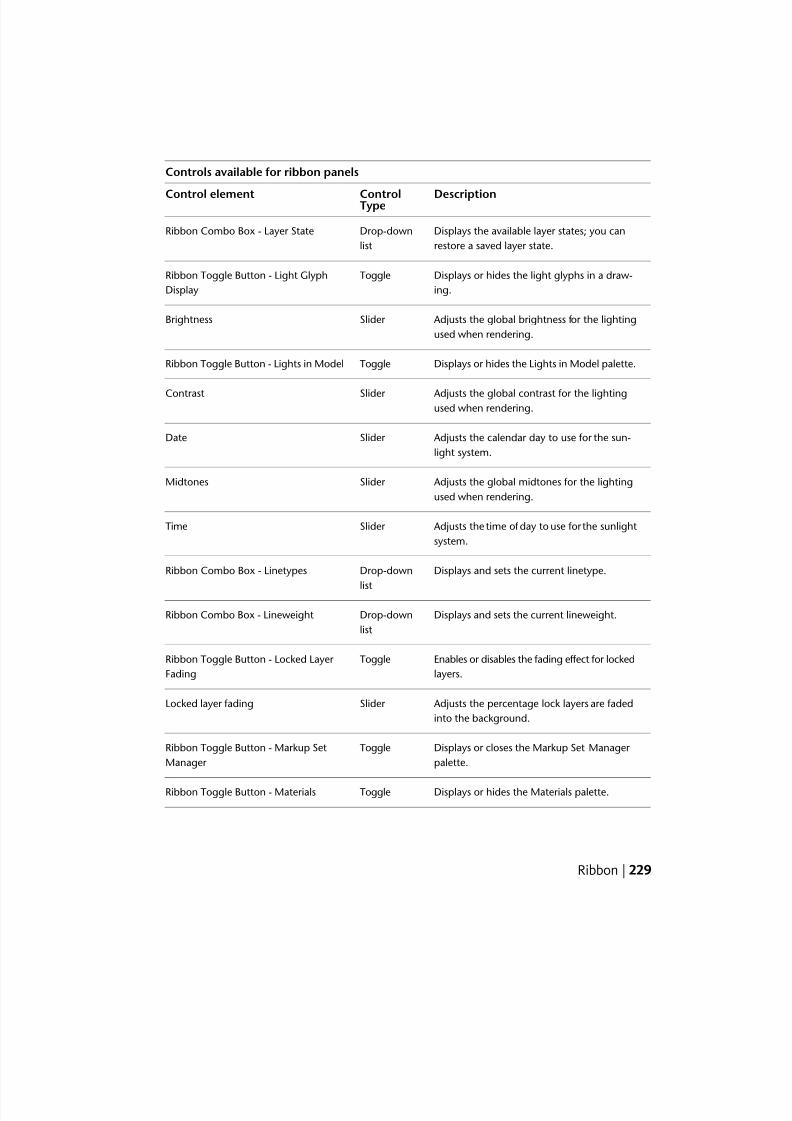
7/23/2019 Acad Customization
http://slidepdf.com/reader/full/acad-customization 237/553
Controls available for ribbon panels
DescriptionControlTypeControl element
Displays the available layer states; you can
restore a saved layer state.
Drop-down
list
Ribbon Combo Box - Layer State
Displays or hides the light glyphs in a draw-
ing.
ToggleRibbon Toggle Button - Light Glyph
Display
Adjusts the global brightness for the lighting
used when rendering.
Slider Brightness
Displays or hides the Lights in Model palette.ToggleRibbon Toggle Button - Lights in Model
Adjusts the global contrast for the lightingused when rendering.
Slider Contrast
Adjusts the calendar day to use for the sun-
light system.
Slider Date
Adjusts the global midtones for the lighting
used when rendering.
Slider Midtones
Adjusts the time of day to use for the sunlight
system.
Slider Time
Displays and sets the current linetype.Drop-down
list
Ribbon Combo Box - Linetypes
Displays and sets the current lineweight.Drop-down
list
Ribbon Combo Box - Lineweight
Enables or disables the fading effect for locked
layers.
ToggleRibbon Toggle Button - Locked Layer
Fading
Adjusts the percentage lock layers are faded
into the background.
Slider Locked layer fading
Displays or closes the Markup Set Manager
palette.
ToggleRibbon Toggle Button - Markup Set
Manager
Displays or hides the Materials palette.ToggleRibbon Toggle Button - Materials
Ribbon | 229
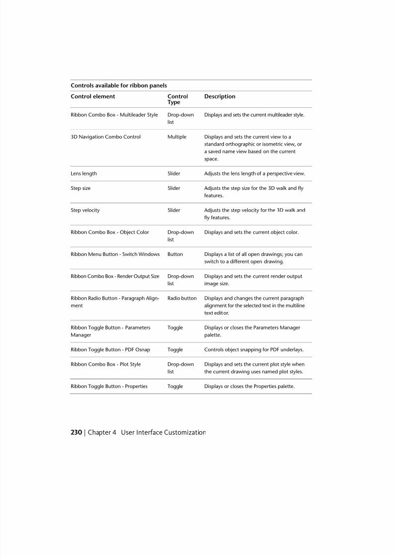
7/23/2019 Acad Customization
http://slidepdf.com/reader/full/acad-customization 238/553
Controls available for ribbon panels
DescriptionControlTypeControl element
Displays and sets the current multileader style.Drop-down
list
Ribbon Combo Box - Multileader Style
Displays and sets the current view to a
standard orthographic or isometric view, or
Multiple3D Navigation Combo Control
a saved name view based on the current
space.
Adjusts the lens length of a perspective view.Slider Lens length
Adjusts the step size for the 3D walk and fly
features.
Slider Step size
Adjusts the step velocity for the 3D walk and
fly features.
Slider Step velocity
Displays and sets the current object color.Drop-down
list
Ribbon Combo Box - Object Color
Displays a list of all open drawings; you can
switch to a different open drawing.
ButtonRibbon Menu Button - Switch Windows
Displays and sets the current render output
image size.
Drop-down
list
Ribbon Combo Box - Render Output Size
Displays and changes the current paragraph
alignment for the selected text in the multiline
text editor.
Radio buttonRibbon Radio Button - Paragraph Align-
ment
Displays or closes the Parameters Manager
palette.
ToggleRibbon Toggle Button - Parameters
Manager
Controls object snapping for PDF underlays.ToggleRibbon Toggle Button - PDF Osnap
Displays and sets the current plot style when
the current drawing uses named plot styles.
Drop-down
list
Ribbon Combo Box - Plot Style
Displays or closes the Properties palette.ToggleRibbon Toggle Button - Properties
230 | Chapter 4 User Interface Customization
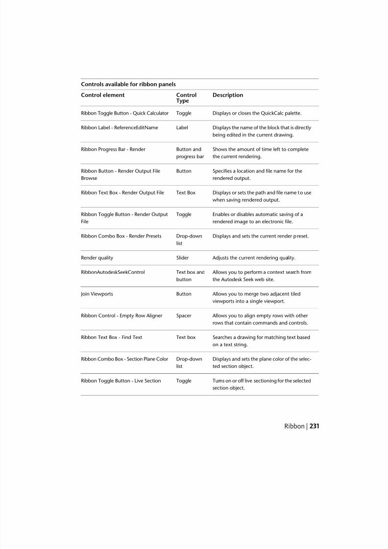
7/23/2019 Acad Customization
http://slidepdf.com/reader/full/acad-customization 239/553
Controls available for ribbon panels
DescriptionControlTypeControl element
Displays or closes the QuickCalc palette.ToggleRibbon Toggle Button - Quick Calculator
Displays the name of the block that is directly
being edited in the current drawing.
LabelRibbon Label - ReferenceEditName
Shows the amount of time left to complete
the current rendering.
Button and
progress bar
Ribbon Progress Bar - Render
Specifies a location and file name for the
rendered output.
ButtonRibbon Button - Render Output File
Browse
Displays or sets the path and file name to usewhen saving rendered output.
Text BoxRibbon Text Box - Render Output File
Enables or disables automatic saving of a
rendered image to an electronic file.
ToggleRibbon Toggle Button - Render Output
File
Displays and sets the current render preset.Drop-down
list
Ribbon Combo Box - Render Presets
Adjusts the current rendering quality.Slider Render quality
Allows you to perform a context search from
the Autodesk Seek web site.
Text box and
button
RibbonAutodeskSeekControl
Allows you to merge two adjacent tiled
viewports into a single viewport.
ButtonJoin Viewports
Allows you to align empty rows with other
rows that contain commands and controls.
Spacer Ribbon Control - Empty Row Aligner
Searches a drawing for matching text based
on a text string.
Text boxRibbon Text Box - Find Text
Displays and sets the plane color of the selec-
ted section object.
Drop-down
list
Ribbon Combo Box - Section Plane Color
Turns on or off live sectioning for the selected
section object.
ToggleRibbon Toggle Button - Live Section
Ribbon | 231
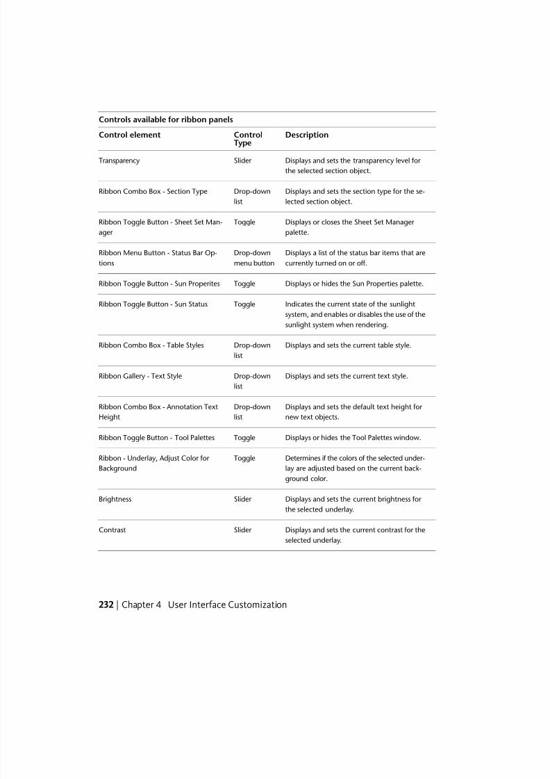
7/23/2019 Acad Customization
http://slidepdf.com/reader/full/acad-customization 240/553
Controls available for ribbon panels
DescriptionControlTypeControl element
Displays and sets the transparency level for
the selected section object.
Slider Transparency
Displays and sets the section type for the se-
lected section object.
Drop-down
list
Ribbon Combo Box - Section Type
Displays or closes the Sheet Set Manager
palette.
ToggleRibbon Toggle Button - Sheet Set Man-
ager
Displays a list of the status bar items that are
currently turned on or off.
Drop-down
menu button
Ribbon Menu Button - Status Bar Op-
tions
Displays or hides the Sun Properties palette.ToggleRibbon Toggle Button - Sun Properites
Indicates the current state of the sunlight
system, and enables or disables the use of the
sunlight system when rendering.
ToggleRibbon Toggle Button - Sun Status
Displays and sets the current table style.Drop-down
list
Ribbon Combo Box - Table Styles
Displays and sets the current text style.Drop-down
list
Ribbon Gallery - Text Style
Displays and sets the default text height for new text objects.
Drop-downlist
Ribbon Combo Box - Annotation TextHeight
Displays or hides the Tool Palettes window.ToggleRibbon Toggle Button - Tool Palettes
Determines if the colors of the selected under-
lay are adjusted based on the current back-
ground color.
ToggleRibbon - Underlay, Adjust Color for
Background
Displays and sets the current brightness for
the selected underlay.
Slider Brightness
Displays and sets the current contrast for the
selected underlay.
Slider Contrast
232 | Chapter 4 User Interface Customization
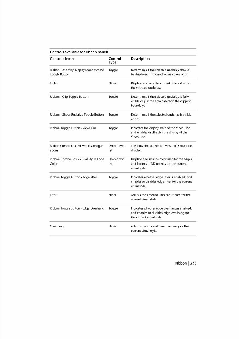
7/23/2019 Acad Customization
http://slidepdf.com/reader/full/acad-customization 241/553
Controls available for ribbon panels
DescriptionControlTypeControl element
Determines if the selected underlay should
be displayed in monochrome colors only.
ToggleRibbon - Underlay, Display Monochrome
Toggle Button
Displays and sets the current fade value for
the selected underlay.
Slider Fade
Determines if the selected underlay is fully
visible or just the area based on the clipping
boundary.
ToggleRibbon - Clip Toggle Button
Determines if the selected underlay is visible
or not.
ToggleRibbon - Show Underlay Toggle Button
Indicates the display state of the ViewCube,
and enables or disables the display of the
ViewCube.
ToggleRibbon Toggle Button - ViewCube
Sets how the active tiled viewport should be
divided.
Drop-down
list
Ribbon Combo Box - Viewport Configur-
ations
Displays and sets the color used for the edges
and isolines of 3D objects for the current
visual style.
Drop-down
list
Ribbon Combo Box - Visual Styles Edge
Color
Indicates whether edge jitter is enabled, andenables or disables edge jitter for the current
visual style.
ToggleRibbon Toggle Button - Edge Jitter
Adjusts the amount lines are jittered for the
current visual style.
Slider Jitter
Indicates whether edge overhang is enabled,
and enables or disables edge overhang for
the current visual style.
ToggleRibbon Toggle Button - Edge Overhang
Adjusts the amount lines overhang for the
current visual style.
Slider Overhang
Ribbon | 233
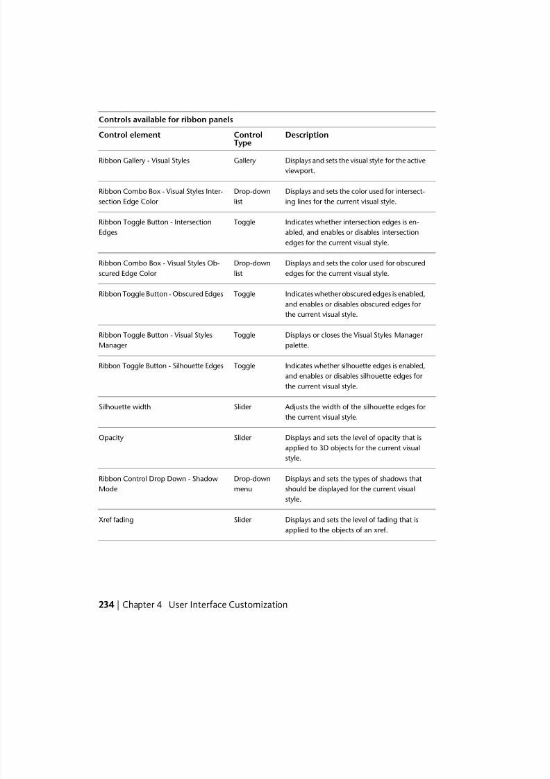
7/23/2019 Acad Customization
http://slidepdf.com/reader/full/acad-customization 242/553
Controls available for ribbon panels
DescriptionControlTypeControl element
Displays and sets the visual style for the active
viewport.
GalleryRibbon Gallery - Visual Styles
Displays and sets the color used for intersect-
ing lines for the current visual style.
Drop-down
list
Ribbon Combo Box - Visual Styles Inter-
section Edge Color
Indicates whether intersection edges is en-
abled, and enables or disables intersection
edges for the current visual style.
ToggleRibbon Toggle Button - Intersection
Edges
Displays and sets the color used for obscured
edges for the current visual style.
Drop-down
list
Ribbon Combo Box - Visual Styles Ob-
scured Edge Color
Indicates whether obscured edges is enabled,
and enables or disables obscured edges for
the current visual style.
ToggleRibbon Toggle Button - Obscured Edges
Displays or closes the Visual Styles Manager
palette.
ToggleRibbon Toggle Button - Visual Styles
Manager
Indicates whether silhouette edges is enabled,
and enables or disables silhouette edges for
the current visual style.
ToggleRibbon Toggle Button - Silhouette Edges
Adjusts the width of the silhouette edges for the current visual style.
Slider Silhouette width
Displays and sets the level of opacity that is
applied to 3D objects for the current visual
style.
Slider Opacity
Displays and sets the types of shadows that
should be displayed for the current visual
style.
Drop-down
menu
Ribbon Control Drop Down - Shadow
Mode
Displays and sets the level of fading that is
applied to the objects of an xref.
Slider Xref fading
234 | Chapter 4 User Interface Customization
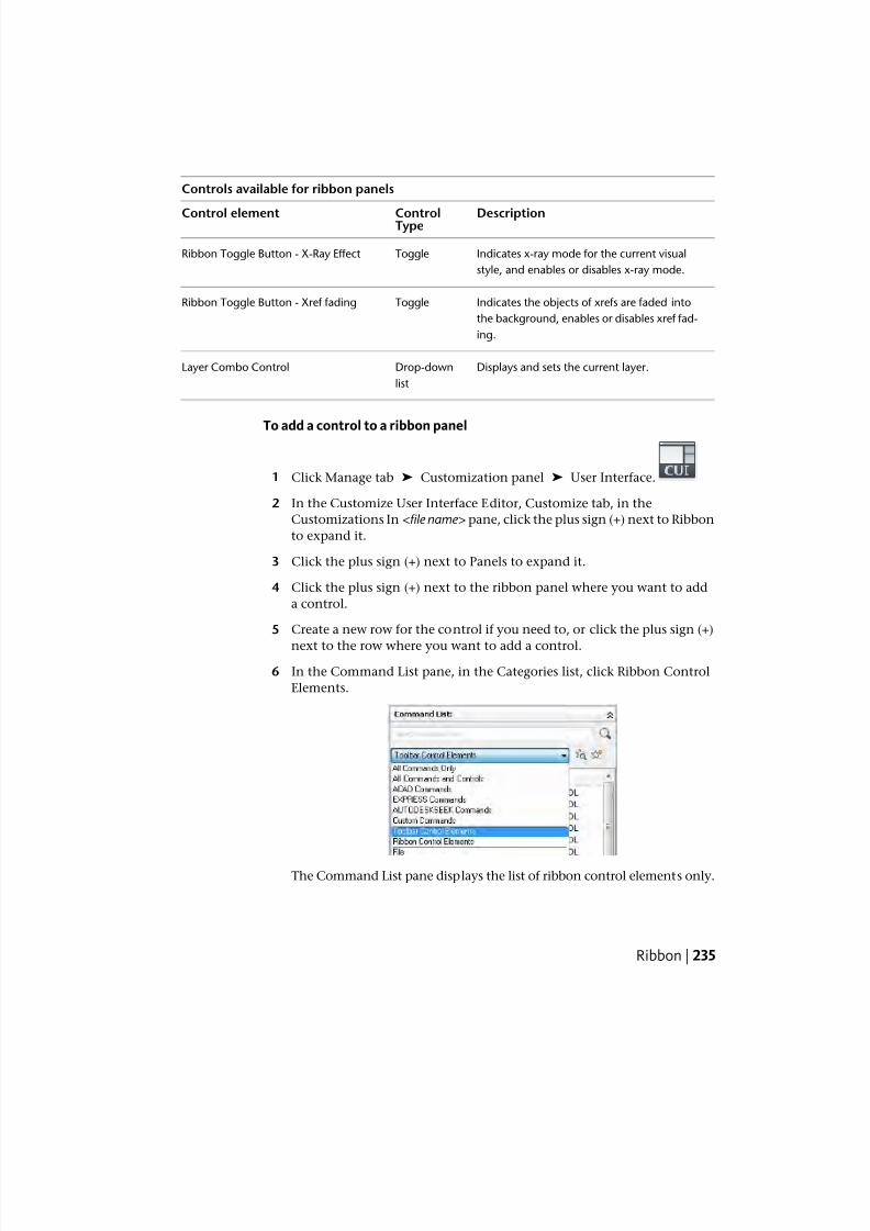
7/23/2019 Acad Customization
http://slidepdf.com/reader/full/acad-customization 243/553
Controls available for ribbon panels
DescriptionControlTypeControl element
Indicates x-ray mode for the current visual
style, and enables or disables x-ray mode.
ToggleRibbon Toggle Button - X-Ray Effect
Indicates the objects of xrefs are faded into
the background, enables or disables xref fad-
ing.
ToggleRibbon Toggle Button - Xref fading
Displays and sets the current layer.Drop-down
list
Layer Combo Control
To add a control to a ribbon panel
1 Click Manage tab ➤ Customization panel ➤ User Interface.
2 In the Customize User Interface Editor, Customize tab, in the
Customizations In <file name> pane, click the plus sign (+) next to Ribbon
to expand it.
3 Click the plus sign (+) next to Panels to expand it.
4 Click the plus sign (+) next to the ribbon panel where you want to add
a control.
5 Create a new row for the control if you need to, or click the plus sign (+)
next to the row where you want to add a control.
6 In the Command List pane, in the Categories list, click Ribbon Control
Elements.
The Command List pane displays the list of ribbon control elements only.
Ribbon | 235
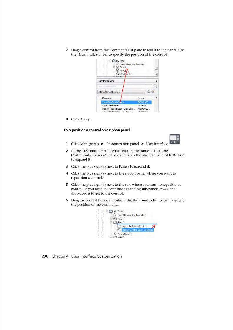
7/23/2019 Acad Customization
http://slidepdf.com/reader/full/acad-customization 244/553
7 Drag a control from the Command List pane to add it to the panel. Use
the visual indicator bar to specify the position of the control.
8 Click Apply.
To reposition a control on a ribbon panel
1 Click Manage tab ➤ Customization panel ➤ User Interface.
2 In the Customize User Interface Editor, Customize tab, in the
Customizations In <file name> pane, click the plus sign (+) next to Ribbon
to expand it.
3 Click the plus sign (+) next to Panels to expand it.
4 Click the plus sign (+) next to the ribbon panel where you want toreposition a control.
5 Click the plus sign (+) next to the row where you want to reposition a
control. If you need to, continue expanding sub-panels, rows, and
drop-downs to get to the control.
6 Drag the control to a new location. Use the visual indicator bar to specify
the position of the command.
236 | Chapter 4 User Interface Customization
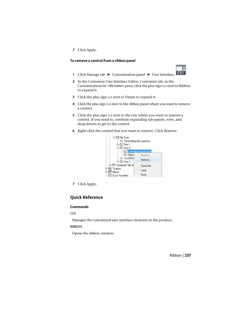
7/23/2019 Acad Customization
http://slidepdf.com/reader/full/acad-customization 245/553
7 Click Apply.
To remove a control from a ribbon panel
1 Click Manage tab ➤ Customization panel ➤ User Interface.
2 In the Customize User Interface Editor, Customize tab, in the
Customizations In <file name> pane, click the plus sign (+) next to Ribbon
to expand it.
3 Click the plus sign (+) next to Panels to expand it.
4 Click the plus sign (+) next to the ribbon panel where you want to remove
a control.
5 Click the plus sign (+) next to the row where you want to remove acontrol. If you need to, continue expanding sub-panels, rows, and
drop-downs to get to the control.
6 Right-click the control that you want to remove. Click Remove.
7 Click Apply.
Quick Reference
Commands
CUI
Manages the customized user interface elements in the product.
RIBBON
Opens the ribbon window.
Ribbon | 237
7/23/2019 Acad Customization
http://slidepdf.com/reader/full/acad-customization 246/553
RIBBONCLOSE
Closes the ribbon window.
Ribbon TabsRibbon tabs control the display and order in which ribbon panels are displayed
on the ribbon. You add ribbon tabs to a workspace to control which ribbon
tabs are displayed on the ribbon.
Ribbon tabs do not contain any commands or controls like a ribbon panel
does; instead, they manage the display of ribbon panels on the ribbon. Once
a ribbon tab is created, you can then add references to any of the ribbon panels
from the Panels node under the Ribbon node in the Customizations In <file
name> pane to the ribbon tab. After references to ribbon panels are added to
a ribbon tab, you can control the initial display order in which ribbon panels
appear on a ribbon tab from the ribbon tab’s node in the Customizations In
<file name> pane.
NOTE Newly created ribbon tabs are not automatically added to a workspace.
To display a new ribbon tab on the ribbon, select the workspace in which you
want the ribbon tab to be displayed with and then use the Workspace Contents
pane to add it to the workspace. For information on adding a ribbon tab to a
workspace, see To display ribbon tabs from the CUI Editor on page 369.
In the Workspace Contents pane, you add and remove ribbon tabs from the
ribbon, which is controlled by the current workspace. Once a ribbon tab has
been added to a workspace, you can control the order in which the tab is
displayed on the ribbon by expanding the Ribbon Tabs node under the
Workspace Contents pane.
From the Workspace Contents pane, you can control the default display of
ribbon tabs and panels; this allows you to keep the associations of ribbon tabs
and panels with a workspace, but turn it off. You can also control the tool
palette group associated with a ribbon tab, and the collapse behavior, resize
order, and orientation of a ribbon panel from the Workspace Contents pane.
238 | Chapter 4 User Interface Customization
7/23/2019 Acad Customization
http://slidepdf.com/reader/full/acad-customization 247/553
The following table describes the properties for the Home - 2D ribbon tab as
they appear in the Properties pane.
Properties for the Home - 2D ribbon tab
ExampleDescriptionPropertiespane item
HomeTitle of the tab; displayed when the ribbon tab
is assigned to a workspace and the Ribbon
palette is displayed.
Display
Text
FullSpecifies whether the ribbon tab is displayed
on its own tab or is merged with the ribbon
Contextual
Display
Type tabs already displayed on the ribbon. The
available options are Full or Merged.
Add to workspacesSpecifies if the ribbon tab is displayed the first
time the CUIx file is loaded as a partial custom-
Default
Display
ization file. The available options are Do Not
Add to Workspaces or Add to Workspaces.
Merge or add tabSpecifies how the ribbon tab is merged or ad-
ded to the ribbon when this CUIx file is loaded
Workspace
Behavior
as a partial customization file. The available
options are Add Tab Only, Merge Tab Only, or
Merge or Add Tab.
HSpecifies the keytip character to access the rib-
bon tab on the ribbon from the keyboard.
KeyTip
ID_TabHomeSpecifies the aliases for the ribbon tab. Click the
[ ] button to open the Aliases dialog box. Each
Aliases
alias in the CUIx file should be unique; it is used
to reference the ribbon tab programmatically.
ID_TabHomeTag that uniquely identifies a panel.Element ID
Display Ribbon Tabs from a Partial CUIx File
When you load ribbon tabs from a partial CUIx file, you can use the Workspace
Behavior property to control how ribbon tabs that might share the same alias
in the main and partial CUIx files are handled. The Add Tab Only option
displays each ribbon tab that is loaded with a workspace as its own tab. While
Ribbon | 239
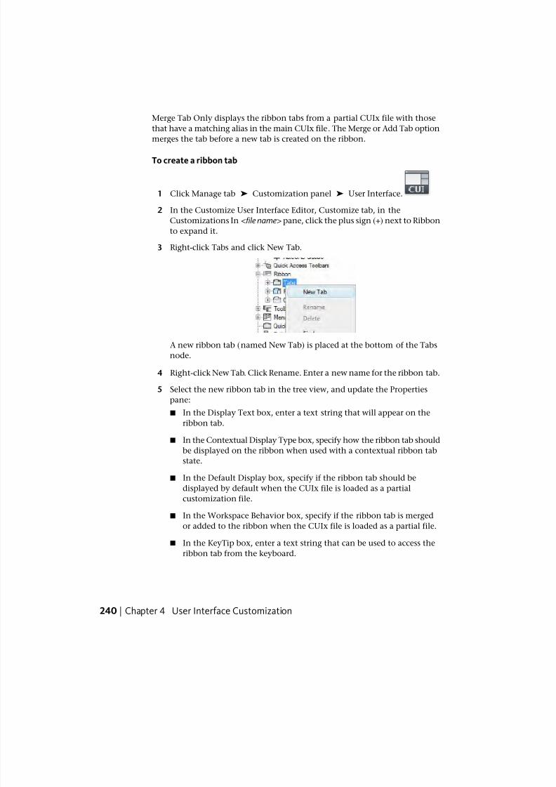
7/23/2019 Acad Customization
http://slidepdf.com/reader/full/acad-customization 248/553
Merge Tab Only displays the ribbon tabs from a partial CUIx file with those
that have a matching alias in the main CUIx file. The Merge or Add Tab option
merges the tab before a new tab is created on the ribbon.
To create a ribbon tab
1 Click Manage tab ➤ Customization panel ➤ User Interface.
2 In the Customize User Interface Editor, Customize tab, in the
Customizations In <file name> pane, click the plus sign (+) next to Ribbon
to expand it.
3 Right-click Tabs and click New Tab.
A new ribbon tab (named New Tab) is placed at the bottom of the Tabs
node.
4 Right-click New Tab. Click Rename. Enter a new name for the ribbon tab.
5 Select the new ribbon tab in the tree view, and update the Properties
pane:
■ In the Display Text box, enter a text string that will appear on theribbon tab.
■ In the Contextual Display Type box, specify how the ribbon tab should
be displayed on the ribbon when used with a contextual ribbon tab
state.
■ In the Default Display box, specify if the ribbon tab should be
displayed by default when the CUIx file is loaded as a partial
customization file.
■ In the Workspace Behavior box, specify if the ribbon tab is merged
or added to the ribbon when the CUIx file is loaded as a partial file.
■ In the KeyTip box, enter a text string that can be used to access the
ribbon tab from the keyboard.
240 | Chapter 4 User Interface Customization
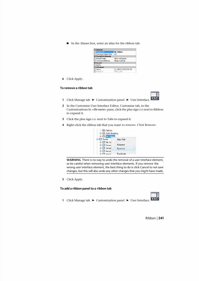
7/23/2019 Acad Customization
http://slidepdf.com/reader/full/acad-customization 249/553
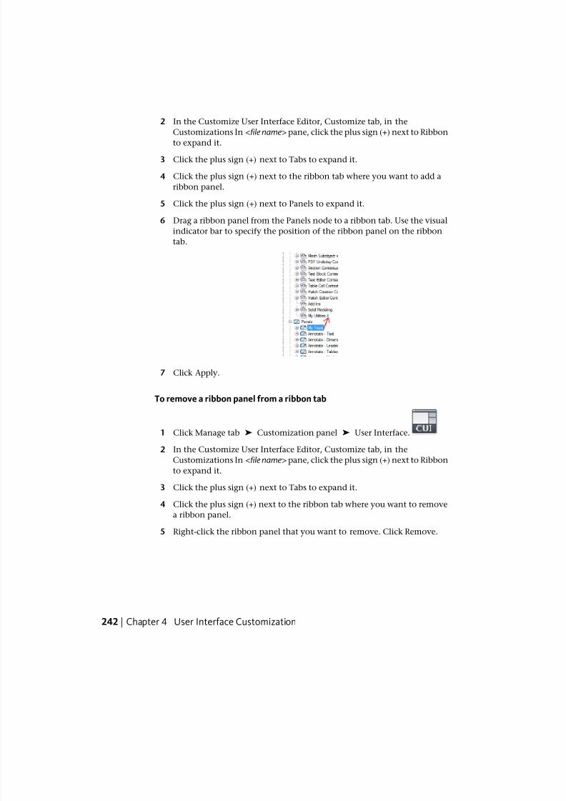
7/23/2019 Acad Customization
http://slidepdf.com/reader/full/acad-customization 250/553
2 In the Customize User Interface Editor, Customize tab, in the
Customizations In <file name> pane, click the plus sign (+) next to Ribbon
to expand it.
3 Click the plus sign (+) next to Tabs to expand it.
4 Click the plus sign (+) next to the ribbon tab where you want to add a
ribbon panel.
5 Click the plus sign (+) next to Panels to expand it.
6 Drag a ribbon panel from the Panels node to a ribbon tab. Use the visual
indicator bar to specify the position of the ribbon panel on the ribbon
tab.
7 Click Apply.
To remove a ribbon panel from a ribbon tab
1 Click Manage tab ➤ Customization panel ➤ User Interface.
2 In the Customize User Interface Editor, Customize tab, in the
Customizations In <file name> pane, click the plus sign (+) next to Ribbon
to expand it.
3 Click the plus sign (+) next to Tabs to expand it.
4 Click the plus sign (+) next to the ribbon tab where you want to remove
a ribbon panel.
5 Right-click the ribbon panel that you want to remove. Click Remove.
242 | Chapter 4 User Interface Customization
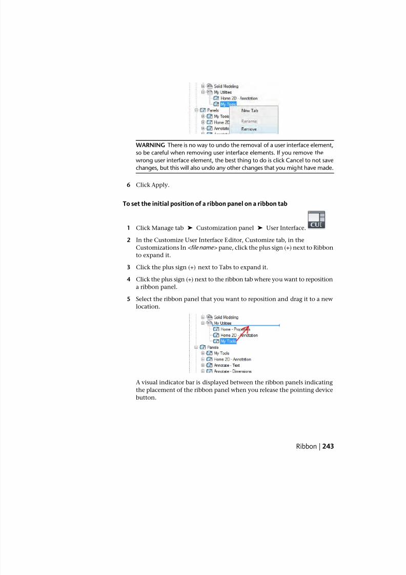
7/23/2019 Acad Customization
http://slidepdf.com/reader/full/acad-customization 251/553
WARNING There is no way to undo the removal of a user interface element,
so be careful when removing user interface elements. If you remove the
wrong user interface element, the best thing to do is click Cancel to not save
changes, but this will also undo any other changes that you might have made.
6 Click Apply.
To set the initial position of a ribbon panel on a ribbon tab
1 Click Manage tab ➤ Customization panel ➤ User Interface.
2 In the Customize User Interface Editor, Customize tab, in the
Customizations In <file name> pane, click the plus sign (+) next to Ribbon
to expand it.
3 Click the plus sign (+) next to Tabs to expand it.
4 Click the plus sign (+) next to the ribbon tab where you want to reposition
a ribbon panel.
5 Select the ribbon panel that you want to reposition and drag it to a newlocation.
A visual indicator bar is displayed between the ribbon panels indicating
the placement of the ribbon panel when you release the pointing device
button.
Ribbon | 243
7/23/2019 Acad Customization
http://slidepdf.com/reader/full/acad-customization 252/553
6 Once the splitter bar is in the place where you want to insert the ribbon
panel, release the pointing device button.
7 Click Apply.
To set the resize style of a ribbon panel on a ribbon tab
1 Click Manage tab ➤ Customization panel ➤ User Interface.
2 In the Customize User Interface Editor, Customize tab, in the
Customizations In <file name> pane, click the plus sign (+) next to Ribbon
to expand it.
3 Click the plus sign (+) next to Tabs to expand it.
4 Click the plus sign (+) next to the ribbon tab that contains the ribbonpanel for which you want to adjust the resize style.
5 Select the ribbon panel that you want to change.
6 In the Properties pane, Resize Style, select an option (Collapse as Needed,
Never Collapse, or Collapse Last).
7 Click Apply.
Quick Reference
Commands
CUI
Manages the customized user interface elements in the product.
RIBBON
Opens the ribbon window.
RIBBONCLOSE
Closes the ribbon window.
Ribbon Contextual Tab StatesRibbon contextual tab states are used to control the display of ribbon panels
on the ribbon when certain commands are active or an object is selected.
244 | Chapter 4 User Interface Customization
7/23/2019 Acad Customization
http://slidepdf.com/reader/full/acad-customization 253/553
You use the same ribbon tabs that you create to control the display of ribbon
panels on the ribbon through a workspace, as those used for ribbon contextual
tab states. Instead of using a workspace to control the display of a ribbon tab,you assign a ribbon tab to one of the predefined contextual states listed under
the Contextual Tab States node in the Customizations In <file name > pane.
Predefined contextual tab states range from selecting an object such as a table
or opening a block in the Block Editor.
To assign a ribbon tab to a contextual tab state
1 Click Manage tab ➤ Customization panel ➤ User Interface.
2 In the Customize User Interface Editor, Customize tab, in the
Customizations In <file name> pane, click the plus sign (+) next to Ribbon
to expand it.3 Click the plus sign (+) next to Tabs to expand it.
4 Click the plus sign (+) next to Contextual Tab States to expand it.
5 Drag a ribbon tab from the Tabs node to a ribbon contextual tab state.
6 Click Apply.
To remove a ribbon tab from a contextual tab state
1 Click Manage tab ➤ Customization panel ➤ User Interface.
2 In the Customize User Interface Editor, Customize tab, in the
Customizations In <file name> pane, click the plus sign (+) next to Ribbon
to expand it.
3 Click the plus sign (+) next to Contextual Tab States to expand it.
4 Click the plus sign (+) next to the contextual tab state that contains theribbon tab you want to remove.
Ribbon | 245
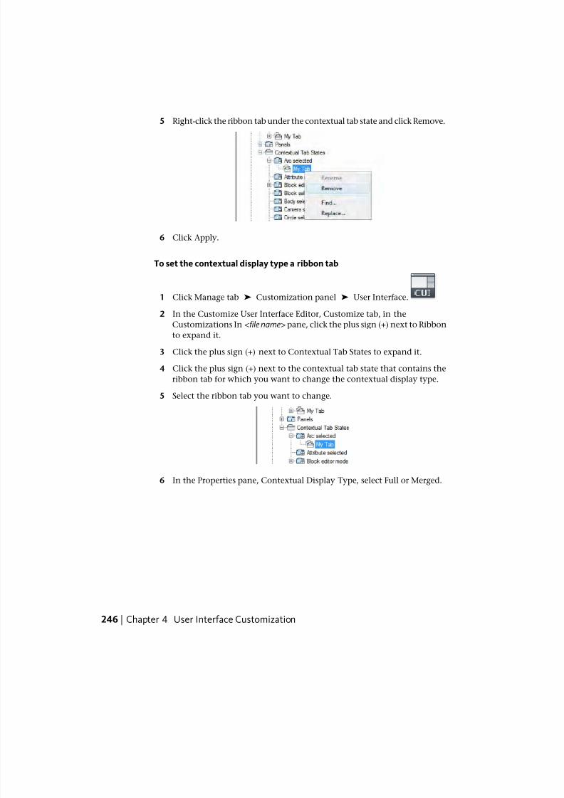
7/23/2019 Acad Customization
http://slidepdf.com/reader/full/acad-customization 254/553
5 Right-click the ribbon tab under the contextual tab state and click Remove.
6 Click Apply.
To set the contextual display type a ribbon tab
1 Click Manage tab ➤ Customization panel ➤ User Interface.
2 In the Customize User Interface Editor, Customize tab, in the
Customizations In <file name> pane, click the plus sign (+) next to Ribbon
to expand it.
3 Click the plus sign (+) next to Contextual Tab States to expand it.
4 Click the plus sign (+) next to the contextual tab state that contains the
ribbon tab for which you want to change the contextual display type.
5 Select the ribbon tab you want to change.
6 In the Properties pane, Contextual Display Type, select Full or Merged.
246 | Chapter 4 User Interface Customization
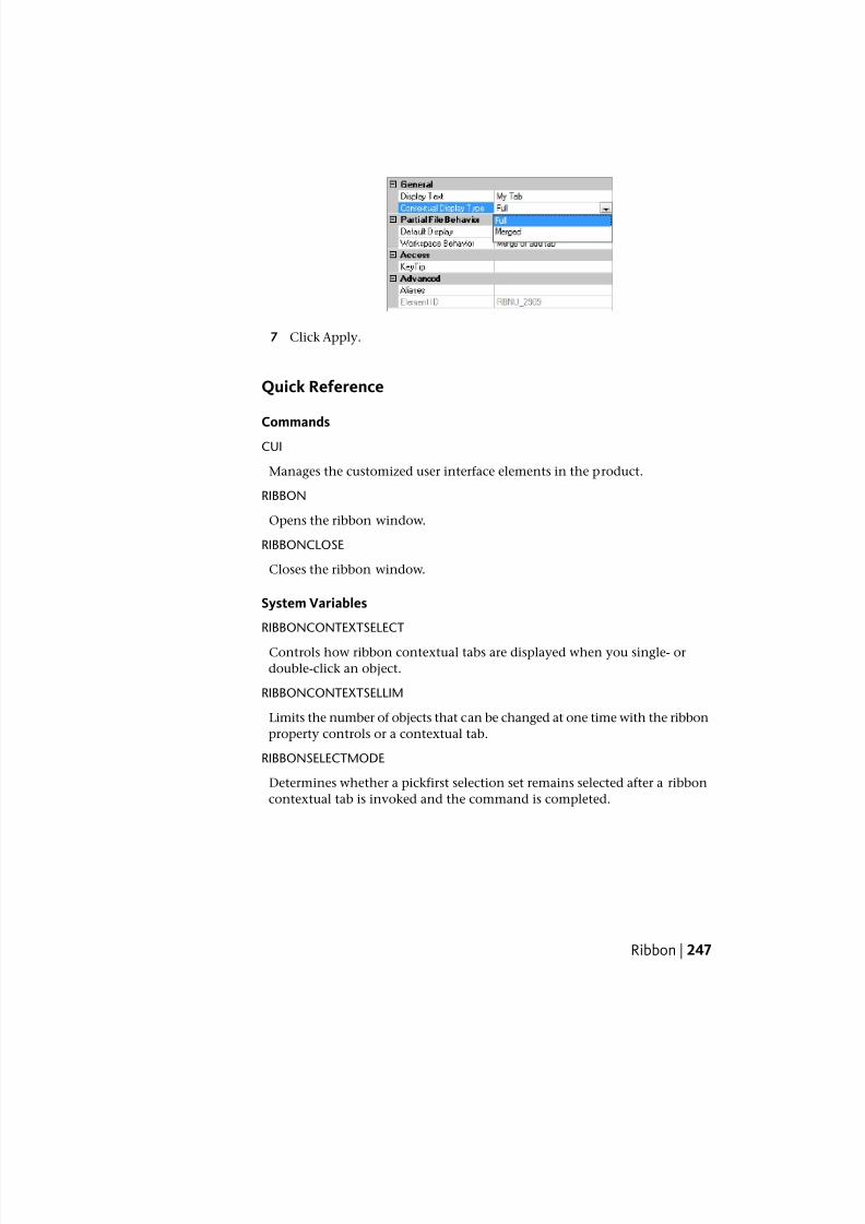
7/23/2019 Acad Customization
http://slidepdf.com/reader/full/acad-customization 255/553
7 Click Apply.
Quick Reference
CommandsCUI
Manages the customized user interface elements in the product.
RIBBON
Opens the ribbon window.
RIBBONCLOSE
Closes the ribbon window.
System Variables
RIBBONCONTEXTSELECT
Controls how ribbon contextual tabs are displayed when you single- or
double-click an object.
RIBBONCONTEXTSELLIM
Limits the number of objects that can be changed at one time with the ribbon
property controls or a contextual tab.
RIBBONSELECTMODE
Determines whether a pickfirst selection set remains selected after a ribbon
contextual tab is invoked and the command is completed.
Ribbon | 247
7/23/2019 Acad Customization
http://slidepdf.com/reader/full/acad-customization 256/553
ToolbarsToolbar customization can be as easy as placing or resizing a toolbar in theapplication window to gain drawing efficiency or space. You can also create
and modify toolbars and flyout toolbars, add commands and controls, and
reposition and remove commands and controls from a toolbar.
Create and Edit ToolbarsSome of the simplest toolbar customizations can make your daily drawing
tasks more efficient. For example, you can consolidate frequently used
commands and controls onto one toolbar, remove buttons that you never
use, or change some simple toolbar properties.
You can also specify information to be displayed when the cursor passes over
a button in the form of a tooltip.
You can add buttons or remove buttons you use infrequently, and rearrange
buttons and toolbars. You can also create your own toolbars and flyout
toolbars, and create or change the button image associated with a command.
When creating a toolbar, you can create a toolbar from scratch, create a copy
of an existing toolbar, or create a toolbar from an existing pull-down menu.
Sub-menu items are not included when a toolbar is created from a pull-down
menu.
NOTE When you create a toolbar, you should determine in which workspaces
you want to display the toolbar. By default, a new toolbar is displayed in all
workspaces.
The following table shows the properties of the Standard toolbar as they appearin the Properties pane.
Properties for the Standard toolbar
ExampleDescriptionProperties paneitem
StandardString used as the caption for the toolbar.Name
Standard Toolbar Text used to describe the element; does not appear in
the user interface.
Description
Add to workspacesSpecifies if the toolbar is displayed when the CUIx file is
loaded as a partial customization file. The available op-
Default Display
248 | Chapter 4 User Interface Customization
7/23/2019 Acad Customization
http://slidepdf.com/reader/full/acad-customization 257/553
Properties for the Standard toolbar
ExampleDescriptionProperties paneitem
tions are Do Not Add to Workspaces or Add to Work-
spaces.
TopSpecifies whether the toolbar is floating or docked (top,
bottom, left, or right) the first time the CUIx file is loaded.
Orientation
0Specifies the location from the left edge of the screen
when the toolbar appears when it is floating, or the loca-
Default X Location
tion when it is docked. If docked, a value of 0 indicates
the left most location in a docked area.
0Specifies the location from the top edge of the screenwhen the toolbar appears when it is floating, or the loca-
Default Y Location
tion when it is docked. If docked, a value of 0 indicates
the top most location in a docked area.
1Specifies the number of rows the items on the toolbar
are displayed in when the toolbar is floating.
Rows
TB_STANDARD,
Standard
Specifies the aliases for the toolbar. Click the [ ] button
to open the Aliases dialog box. Each alias in the CUIx file
Aliases
should be unique and it is used to reference the toolbar
programmatically.
ID_TbStandardTag that uniquely identifies a toolbar.Element ID
NOTE The properties On By Default, Orientation, Default X Location, Default Y
Location, and Rows are used only the first time the CUIx file is loaded and when
no default workspace is set. After a toolbar is loaded the first time, a workspace is
used to control the Appearance properties of a toolbar. See the procedure To
change the properties of a toolbar on page 376 for more information.
When you create a new toolbar, the first task you need to do is to provide a
name for it. A new toolbar has no commands or controls assigned to it. If a
toolbar has no commands or controls on it, it is ignored by the program until
you add at least one command or control to it. You add commands and
controls to a toolbar by dragging a command or control from an existing
toolbar or the Command List pane and dropping it onto a toolbar. Once a
command or control has been added to a toolbar, you can change the text
Toolbars | 249
7/23/2019 Acad Customization
http://slidepdf.com/reader/full/acad-customization 258/553
that is displayed in the tooltip when the cursor hovers over top of the button
by changing the Name property that is displayed in the Properties pane.
Customize Toolbars with the Toolbar Preview Pane
You can customize a toolbar using the tree view under the Customizations In
<file name> pane or the Toolbar Preview pane. The Toolbar Preview pane allows
you to add and remove commands or controls visually in real-time instead of
just using the tree view. You can also interactively drag a command or control
in the preview pane to reposition it.
Customize Toolbars from the Application Window
The program allows you to customize toolbars that are displayed in the
application when the Customize User Interface (CUI) Editor is open. You drag
commands from the Command List pane and drop then directly onto a visible
toolbar that is docked or floating in the application window. You can alsoremove, reposition, or copy commands on a visible toolbar while the CUI
Editor is open.
Create Ribbon Panels from Toolbars
New ribbon panels can be created from a toolbar by dragging existing toolbars
from the Toolbars node under the Customizations In <file name> pane to the
Panels node under Ribbon in the Customizations In <file name> pane. When
the toolbar is dropped, you are prompted to convert a copy of the toolbar to
a ribbon panel. See Ribbon Panels on page 201 for more information about
customizing ribbon panels.
To display a toolbar
■ Do one of the following:
To display toolbars from the user interface on page 363
To display toolbars using the CUI Editor on page 374
To create a toolbar
1 Click Manage tab ➤ Customization panel ➤ User Interface.
2 In the Customize User Interface Editor, Customize tab, in the
Customizations In <file name> pane, right-click Toolbars. Click New
Toolbar.
250 | Chapter 4 User Interface Customization
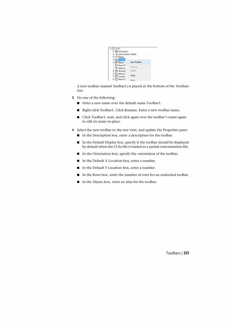
7/23/2019 Acad Customization
http://slidepdf.com/reader/full/acad-customization 259/553
A new toolbar (named Toolbar1) is placed at the bottom of the Toolbars
tree.
3 Do one of the following:
■ Enter a new name over the default name Toolbar1.
■ Right-click Toolbar1. Click Rename. Enter a new toolbar name.
■ Click Toolbar1, wait, and click again over the toolbar’s name again
to edit its name in-place.
4 Select the new toolbar in the tree view, and update the Properties pane:
■ In the Description box, enter a description for the toolbar.
■ In the Default Display box, specify if the toolbar should be displayed
by default when the CUIx file is loaded as a partial customization file.
■ In the Orientation box, specify the orientation of the toolbar.
■ In the Default X Location box, enter a number.
■ In the Default Y Location box, enter a number.
■ In the Rows box, enter the number of rows for an undocked toolbar.
■ In the Aliases box, enter an alias for the toolbar.
Toolbars | 251
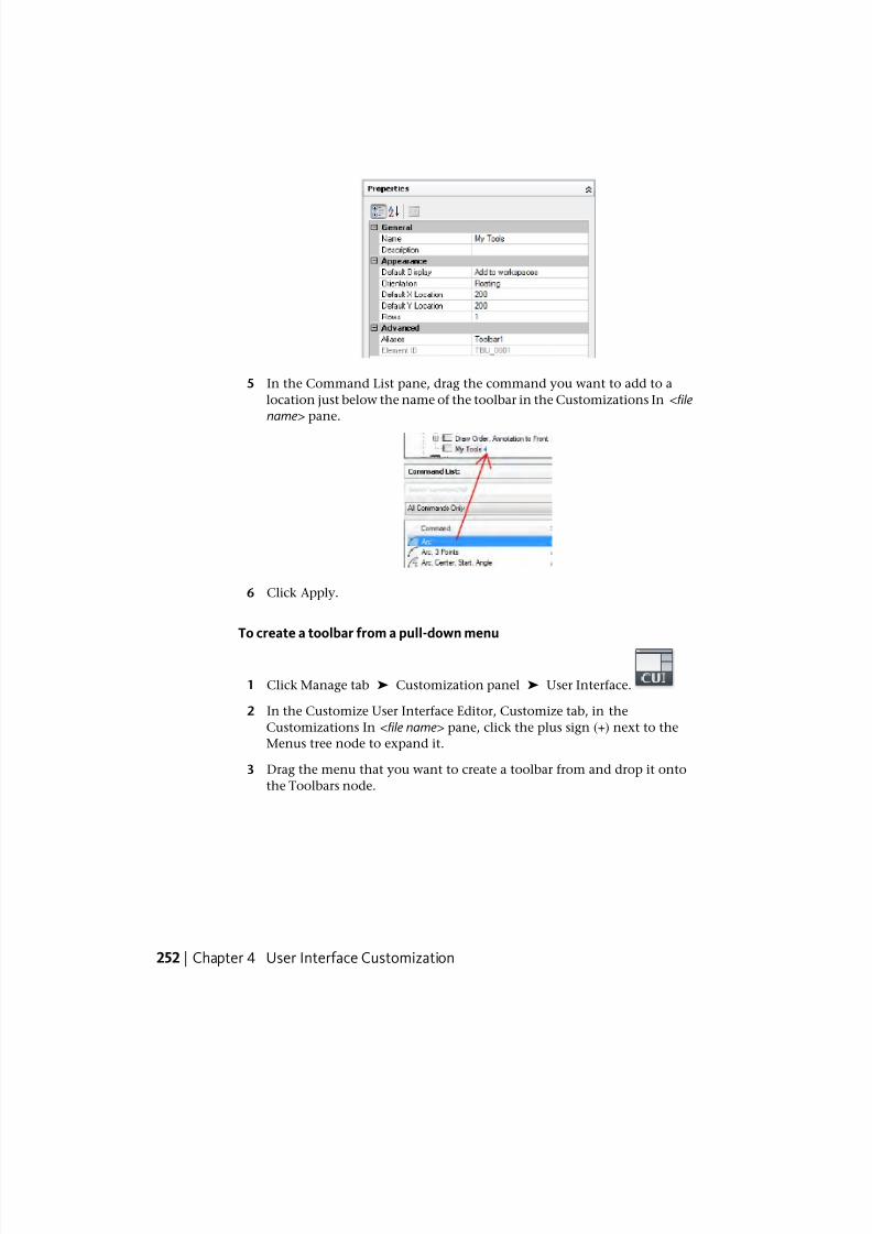
7/23/2019 Acad Customization
http://slidepdf.com/reader/full/acad-customization 260/553
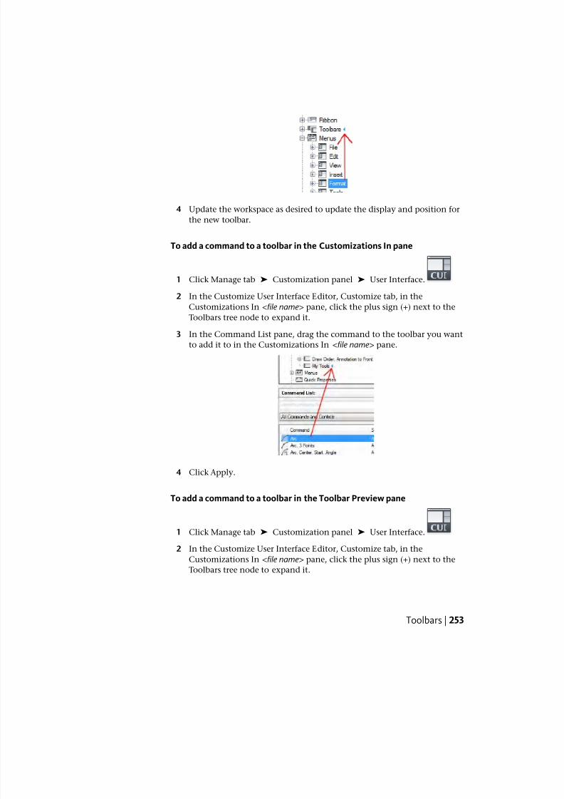
7/23/2019 Acad Customization
http://slidepdf.com/reader/full/acad-customization 261/553
4 Update the workspace as desired to update the display and position for
the new toolbar.
To add a command to a toolbar in the Customizations In pane
1 Click Manage tab ➤ Customization panel ➤ User Interface.
2 In the Customize User Interface Editor, Customize tab, in the
Customizations In <file name> pane, click the plus sign (+) next to the
Toolbars tree node to expand it.
3 In the Command List pane, drag the command to the toolbar you want
to add it to in the Customizations In <file name> pane.
4 Click Apply.
To add a command to a toolbar in the Toolbar Preview pane
1 Click Manage tab ➤ Customization panel ➤ User Interface.
2 In the Customize User Interface Editor, Customize tab, in the
Customizations In <file name> pane, click the plus sign (+) next to theToolbars tree node to expand it.
Toolbars | 253
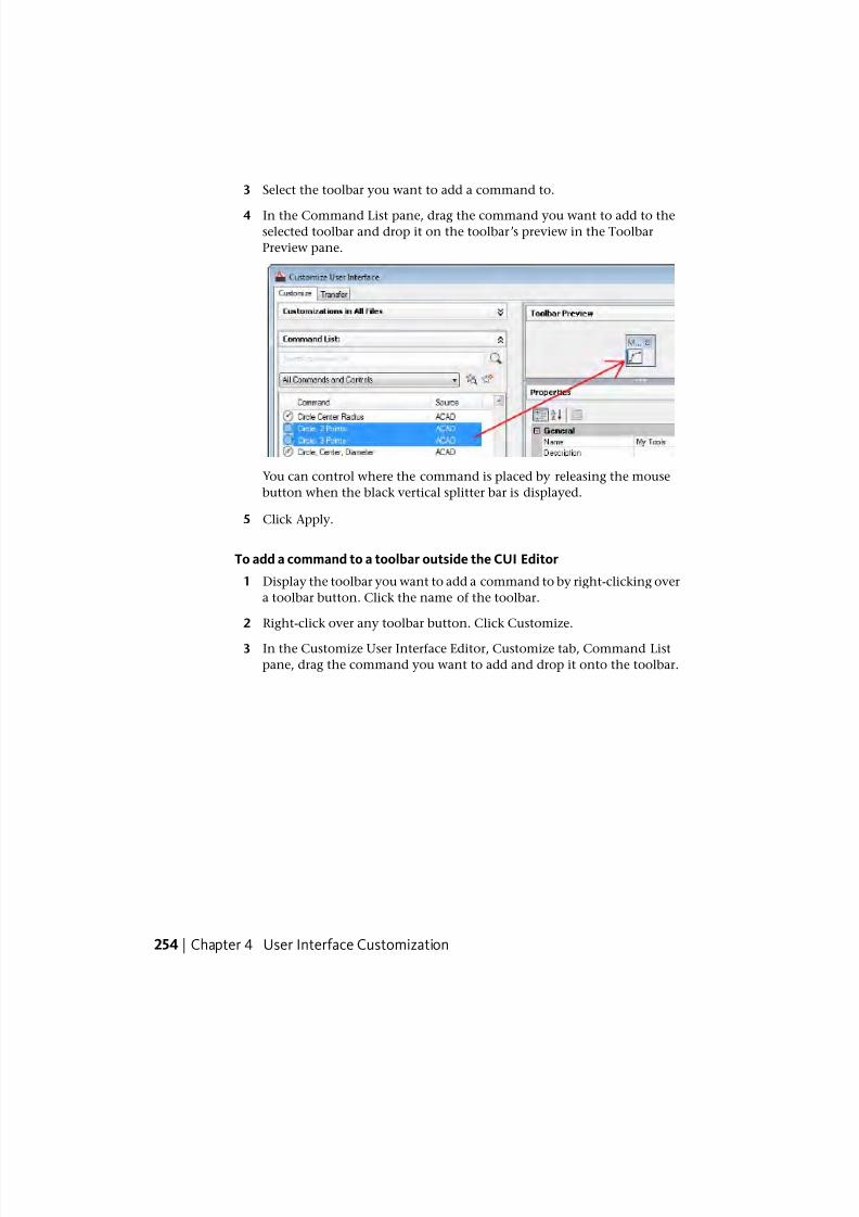
7/23/2019 Acad Customization
http://slidepdf.com/reader/full/acad-customization 262/553
3 Select the toolbar you want to add a command to.
4 In the Command List pane, drag the command you want to add to theselected toolbar and drop it on the toolbar’s preview in the Toolbar
Preview pane.
You can control where the command is placed by releasing the mouse
button when the black vertical splitter bar is displayed.
5 Click Apply.
To add a command to a toolbar outside the CUI Editor
1 Display the toolbar you want to add a command to by right-clicking over
a toolbar button. Click the name of the toolbar.
2 Right-click over any toolbar button. Click Customize.
3 In the Customize User Interface Editor, Customize tab, Command List
pane, drag the command you want to add and drop it onto the toolbar.
254 | Chapter 4 User Interface Customization
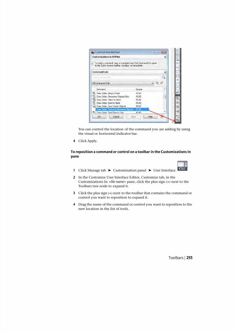
7/23/2019 Acad Customization
http://slidepdf.com/reader/full/acad-customization 263/553
You can control the location of the command you are adding by using
the visual or horizontal indicator bar.
4 Click Apply.
To reposition a command or control on a toolbar in the Customizations Inpane
1 Click Manage tab ➤ Customization panel ➤ User Interface.
2 In the Customize User Interface Editor, Customize tab, in the
Customizations In <file name> pane, click the plus sign (+) next to the
Toolbars tree node to expand it.
3 Click the plus sign (+) next to the toolbar that contains the command or
control you want to reposition to expand it.
4 Drag the name of the command or control you want to reposition to the
new location in the list of tools.
Toolbars | 255
7/23/2019 Acad Customization
http://slidepdf.com/reader/full/acad-customization 264/553
While dragging the command or control, use the visual indicator bar to
specify the new position of the command or control. When the left arrow
appears, the command or control is moved to the front of the toolbar.
5 Click Apply.
To reposition a command or control on a toolbar in the Toolbar Preview
pane
1 Click Manage tab ➤ Customization panel ➤ User Interface.
2 In the Customize User Interface Editor, Customize tab, in the
Customizations In <file name> pane, click the plus sign (+) next to the
Toolbars tree node to expand it.
3 Select the toolbar that contains the command or control you want to
reposition.
4 In the Toolbar Preview, drag the command or control that you want to
reposition.
While dragging the command or control, use the visual indicator bar to
specify the new position of the command or control.
5 Click Apply.
To reposition a command on a toolbar outside the CUI Editor
1 Display the toolbar you want to reposition a command on by
right-clicking over a toolbar button. Click the name of the toolbar.
2 Right-click over any toolbar button. Click Customize.
256 | Chapter 4 User Interface Customization
7/23/2019 Acad Customization
http://slidepdf.com/reader/full/acad-customization 265/553
The Customize User Interface (CUI) Editor is displayed.
3 Drag the command on the toolbar that you want to reposition.
While dragging the command, use the visual indicator bar to specify the
new position of the command.
4 Click Apply.
To remove a command or control from a toolbar in the Customizations Inpane
1 Click Manage tab ➤ Customization panel ➤ User Interface.
2 In the Customize User Interface Editor, Customize tab, in the
Customizations In <file name> pane, click the plus sign (+) next to the
Toolbars tree node to expand it.
3 Click the plus sign (+) next to a toolbar that contains the command or
control you want to remove.
4 Right-click the name of the command or control you want to remove.Click Remove.
5 Click Apply.
Toolbars | 257
7/23/2019 Acad Customization
http://slidepdf.com/reader/full/acad-customization 266/553
To remove a command or control from a toolbar in the Toolbar Preview pane
1 Click Manage tab ➤ Customization panel ➤ User Interface.
2 In the Customize User Interface Editor, Customize tab, in the
Customizations In <file name> pane, click the plus sign (+) next to the
Toolbars tree node to expand it.
3 Select the toolbar that contains the command or control you want to
reposition.
4 In the Toolbar Preview pane, drag the command or control that you want
to remove and drop it outside of the preview.
5 Click Apply.
To remove a command from a toolbar outside the CUI Editor
1 Display the toolbar from which you want to remove a command by
right-clicking over a toolbar button. Click the name of the toolbar.
2 Right-click over any toolbar button. Click Customize.
The Customize User Interface (CUI) Editor is displayed.
3 Drag the command you want to remove from the toolbar and drop it
over the drawing window.
4 Click OK to confirm the deletion of the command from the toolbar.
258 | Chapter 4 User Interface Customization
7/23/2019 Acad Customization
http://slidepdf.com/reader/full/acad-customization 267/553
5 In the Customize User Interface (CUI) Editor, click Apply.
To change properties of a toolbar
1 Click Manage tab ➤ Customization panel ➤ User Interface.
2 In the Customize User Interface Editor, Customize tab, in the
Customizations In <file name> pane, click the plus sign (+) next to the
Toolbars tree node to expand it.
NOTE Making changes to a toolbar ’s properties here only affect the initial
appearance of the toolbar after the CUIx file has been loaded. To control the
appearance of a toolbar, it is best to use a workspace.
3 Select the toolbar whose properties you want to change.
4 In the Properties pane, make your changes.
5 Click Apply.
To change the tooltip of a command
1 Click Manage tab ➤ Customization panel ➤ User Interface.
2 In the Customize User Interface Editor, Customize tab, in the
Customizations In <file name> pane, click the plus sign (+) next to the
Toolbars tree node to expand it.
3 Select the toolbar whose tooltip text you want to change.
4 In the Properties pane, Display section, make the desired change to the
Name property (not the Command Name or Command Display Name
properties), and the Description and Extended Help File properties.
5 Click Apply.
Toolbars | 259
7/23/2019 Acad Customization
http://slidepdf.com/reader/full/acad-customization 268/553
Quick Reference
Commands
CUI
Manages the customized user interface elements in the product.
QUICKCUI
Displays the Customize User Interface Editor in a collapsed state.
RIBBON
Opens the ribbon window.
RIBBONCLOSE
Closes the ribbon window.
System Variables
TOOLTIPS
Controls the display of tooltips on the ribbon, toolbars, and other user
interface elements.
Add Flyouts to a ToolbarYou can use flyouts to group related commands together on a toolbar.
A flyout is a set of commands nested under a single button on a toolbar. Flyout
buttons have a black triangle in the lower-right corner. To create a flyout, you
can start from scratch, or drag an existing toolbar or drag pull-down menu
onto a toolbar. When a pull-down menu is dragged onto a toolbar, a new
toolbar is created and a flyout is created in the position that the pull-down
menu was dropped onto the toolbar.
The following table shows the properties for the Zoom flyout as they appear
in the Properties pane.
Properties for the Zoom flyout on the Standard toolbar
ExampleDescriptionProperties pane item
ZoomString that does not appear in the user interface un-
less the property Use Own Button is set to Yes.
Name
260 | Chapter 4 User Interface Customization
7/23/2019 Acad Customization
http://slidepdf.com/reader/full/acad-customization 269/553
Properties for the Zoom flyout on the Standard toolbar
ExampleDescriptionProperties pane item
Text used to describe the element, does not appear
in the user interface.
Description
TB_ZOOM A read-only value used to specify which toolbar is
being referenced to create the flyout.
Source Toolbar
NoControls whether the last used toolbar button is set
as the current button or not. The possible values are
Yes or No.
Use Own Button
RCDATA_16_ZOOMID string of the small-image resource (16 × 16 bit-
map). The string must include alphanumeric charac-
Small Image
ters with no punctuation other than a hyphen (-) or
an underscore (_). It can also be a user-defined bit-
map. Click the [ ] button to open the Select Image
File dialog box.
RCDATA_16_ZOOMID string of the large-image resource (32 × 32 bit-
map). If the specified bitmap is not 32 × 32, the
Large Image
program scales it to that size. The string must include
alphanumeric characters with no punctuation other
than a hyphen (-) or an underscore (_). It can also be
a user-defined bitmap. Click the [ ] button to open
the Select Image File dialog box
WARNING Do not change the aliases for a toolbar that is being used as a flyout;
otherwise the link between the toolbar and flyout will become broken.
To create a flyout toolbar from scratch
1 Click Manage tab ➤ Customization panel ➤ User Interface.
2 In the Customize User Interface Editor, Customize tab, in the
Customizations In <file name> pane, click the plus sign (+) next to the
Toolbars tree node to expand it.
3 Right-click the toolbar to which you want to add a flyout toolbar. Click
New Flyout.
Toolbars | 261
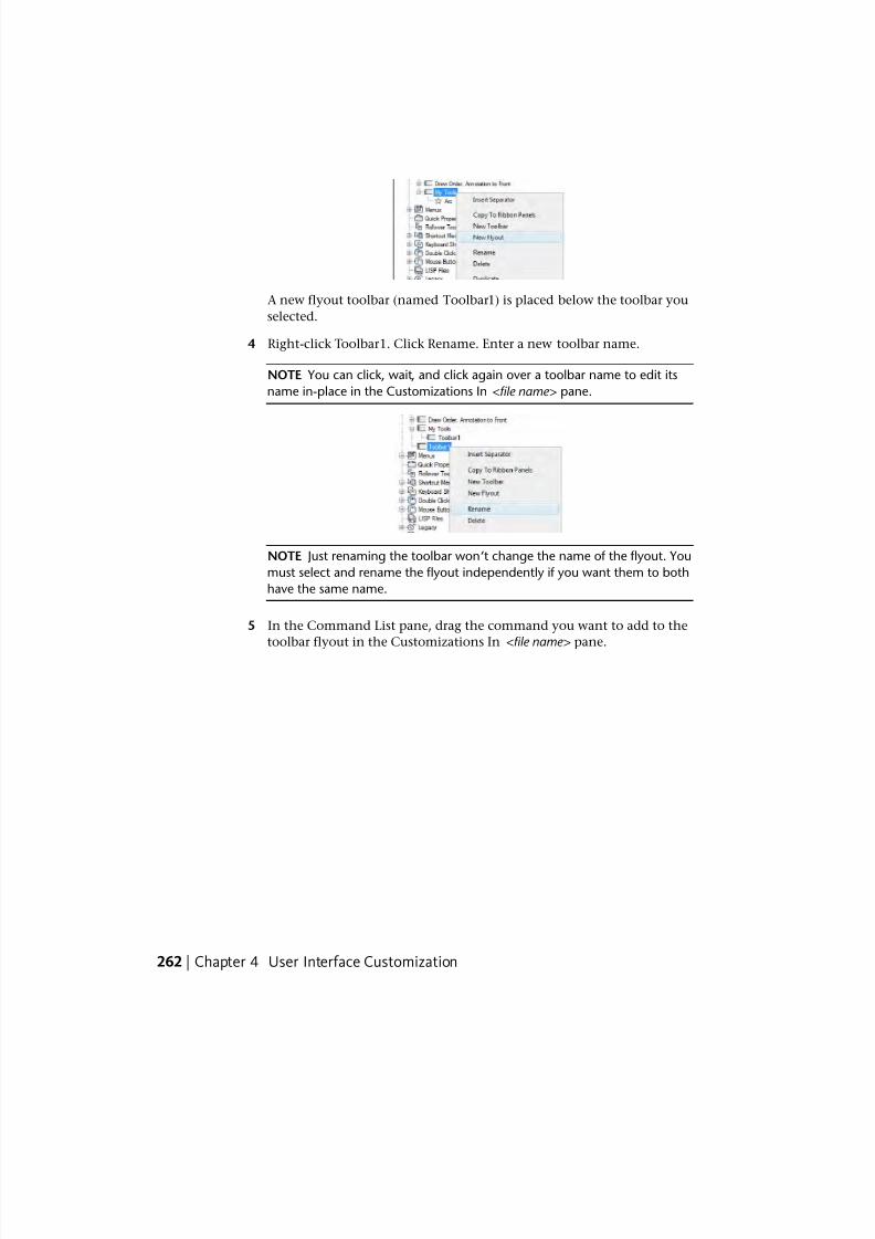
7/23/2019 Acad Customization
http://slidepdf.com/reader/full/acad-customization 270/553
A new flyout toolbar (named Toolbar1) is placed below the toolbar you
selected.
4 Right-click Toolbar1. Click Rename. Enter a new toolbar name.
NOTE You can click, wait, and click again over a toolbar name to edit its
name in-place in the Customizations In <file name> pane.
NOTE Just renaming the toolbar won’t change the name of the flyout. You
must select and rename the flyout independently if you want them to both
have the same name.
5 In the Command List pane, drag the command you want to add to the
toolbar flyout in the Customizations In <file name> pane.
262 | Chapter 4 User Interface Customization
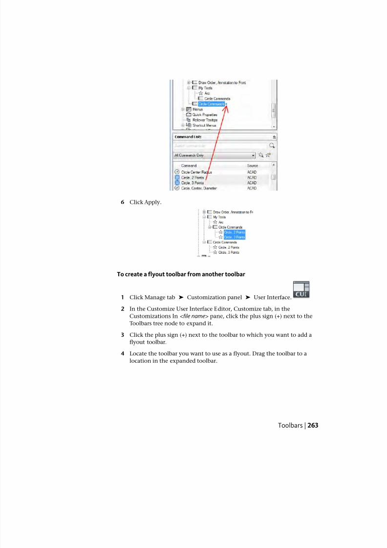
7/23/2019 Acad Customization
http://slidepdf.com/reader/full/acad-customization 271/553
6 Click Apply.
To create a flyout toolbar from another toolbar
1 Click Manage tab ➤ Customization panel ➤ User Interface.
2 In the Customize User Interface Editor, Customize tab, in the
Customizations In <file name> pane, click the plus sign (+) next to the
Toolbars tree node to expand it.
3 Click the plus sign (+) next to the toolbar to which you want to add a
flyout toolbar.
4 Locate the toolbar you want to use as a flyout. Drag the toolbar to a
location in the expanded toolbar.
Toolbars | 263
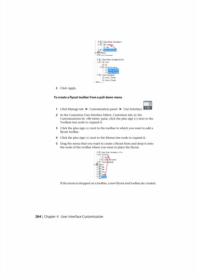
7/23/2019 Acad Customization
http://slidepdf.com/reader/full/acad-customization 272/553
5 Click Apply.
To create a flyout toolbar from a pull-down menu
1 Click Manage tab ➤ Customization panel ➤ User Interface.
2 In the Customize User Interface Editor, Customize tab, in the
Customizations In <file name> pane, click the plus sign (+) next to the
Toolbars tree node to expand it.
3 Click the plus sign (+) next to the toolbar to which you want to add a
flyout toolbar.
4 Click the plus sign (+) next to the Menus tree node to expand it.
5 Drag the menu that you want to create a flyout from and drop it onto
the node of the toolbar where you want to place the flyout.
If the menu is dropped on a toolbar, a new flyout and toolbar are created.
264 | Chapter 4 User Interface Customization
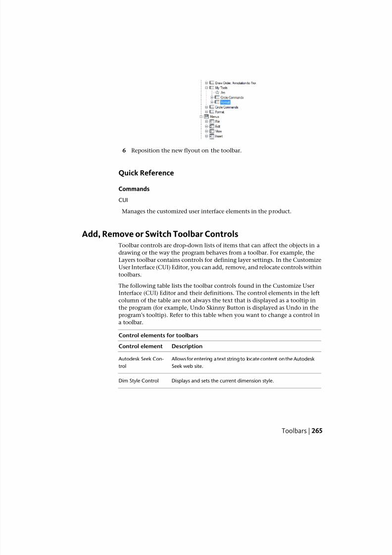
7/23/2019 Acad Customization
http://slidepdf.com/reader/full/acad-customization 273/553
6 Reposition the new flyout on the toolbar.
Quick Reference
Commands
CUI
Manages the customized user interface elements in the product.
Add, Remove or Switch Toolbar ControlsToolbar controls are drop-down lists of items that can affect the objects in a
drawing or the way the program behaves from a toolbar. For example, the
Layers toolbar contains controls for defining layer settings. In the Customize
User Interface (CUI) Editor, you can add, remove, and relocate controls within
toolbars.
The following table lists the toolbar controls found in the Customize User
Interface (CUI) Editor and their definitions. The control elements in the leftcolumn of the table are not always the text that is displayed as a tooltip in
the program (for example, Undo Skinny Button is displayed as Undo in the
program's tooltip). Refer to this table when you want to change a control in
a toolbar.
Control elements for toolbars
DescriptionControl element
Allows for entering a text string to locate content on the Autodesk
Seek web site.
Autodesk Seek Con-
trol
Displays and sets the current dimension style.Dim Style Control
Toolbars | 265
7/23/2019 Acad Customization
http://slidepdf.com/reader/full/acad-customization 274/553
Control elements for toolbars
DescriptionControl element
Allows for searching on a text string contained in the current
drawing.
Find Text Control
Displays the current layer and allows you to set a layer current.Layer Control
Displays and sets the current linetype.Line Type Control
Displays and sets the current line weight.Line Weight Control
Displays and sets the current multileader style.Multileader Style
Control
Displays and sets the current named view.Named View Control
Displays and sets the current color.OPT Color Control
Displays and sets the current plot style.Plot Style Control
Allows you to reverse the previous undo or undoes.Redo Skinny Button
Control
Displays the name of the xref being edited.Reference Block
Name Control
Displays and sets the current table style.Table Style Control
Displays and sets the current text style.Text Style Control
Displays the current UCS and allows you to restore a saved UCS.UCS Control
Allows you to undo the previous action or actions.Undo Skinny Button
Control
Displays and sets the current standard 3D view for a viewport. View Control
Displays and sets the current scale for a floating viewport. Viewport Scale Con-
trol
Displays the current workspace and allows you to set a workspacecurrent.
Workspace Control
266 | Chapter 4 User Interface Customization
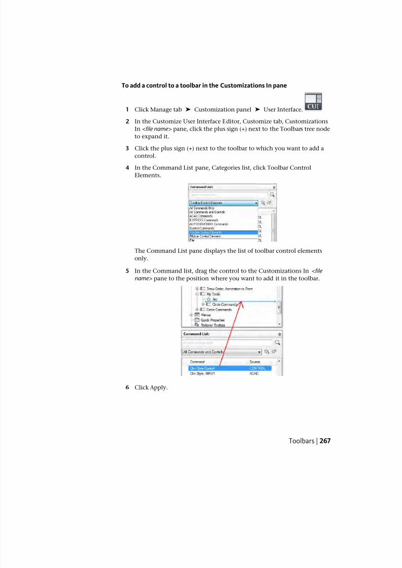
7/23/2019 Acad Customization
http://slidepdf.com/reader/full/acad-customization 275/553
To add a control to a toolbar in the Customizations In pane
1 Click Manage tab ➤ Customization panel ➤ User Interface.
2 In the Customize User Interface Editor, Customize tab, Customizations
In <file name> pane, click the plus sign (+) next to the Toolbars tree node
to expand it.
3 Click the plus sign (+) next to the toolbar to which you want to add a
control.
4 In the Command List pane, Categories list, click Toolbar Control
Elements.
The Command List pane displays the list of toolbar control elements
only.
5 In the Command list, drag the control to the Customizations In <file
name> pane to the position where you want to add it in the toolbar.
6 Click Apply.
Toolbars | 267
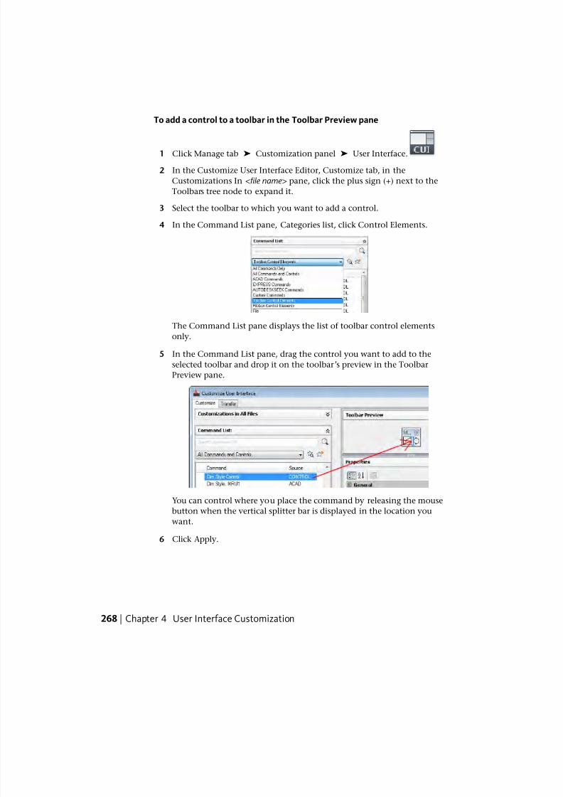
7/23/2019 Acad Customization
http://slidepdf.com/reader/full/acad-customization 276/553
To add a control to a toolbar in the Toolbar Preview pane
1 Click Manage tab ➤ Customization panel ➤ User Interface.
2 In the Customize User Interface Editor, Customize tab, in the
Customizations In <file name> pane, click the plus sign (+) next to the
Toolbars tree node to expand it.
3 Select the toolbar to which you want to add a control.
4 In the Command List pane, Categories list, click Control Elements.
The Command List pane displays the list of toolbar control elements
only.
5 In the Command List pane, drag the control you want to add to the
selected toolbar and drop it on the toolbar’s preview in the Toolbar
Preview pane.
You can control where you place the command by releasing the mouse
button when the vertical splitter bar is displayed in the location you
want.
6 Click Apply.
268 | Chapter 4 User Interface Customization
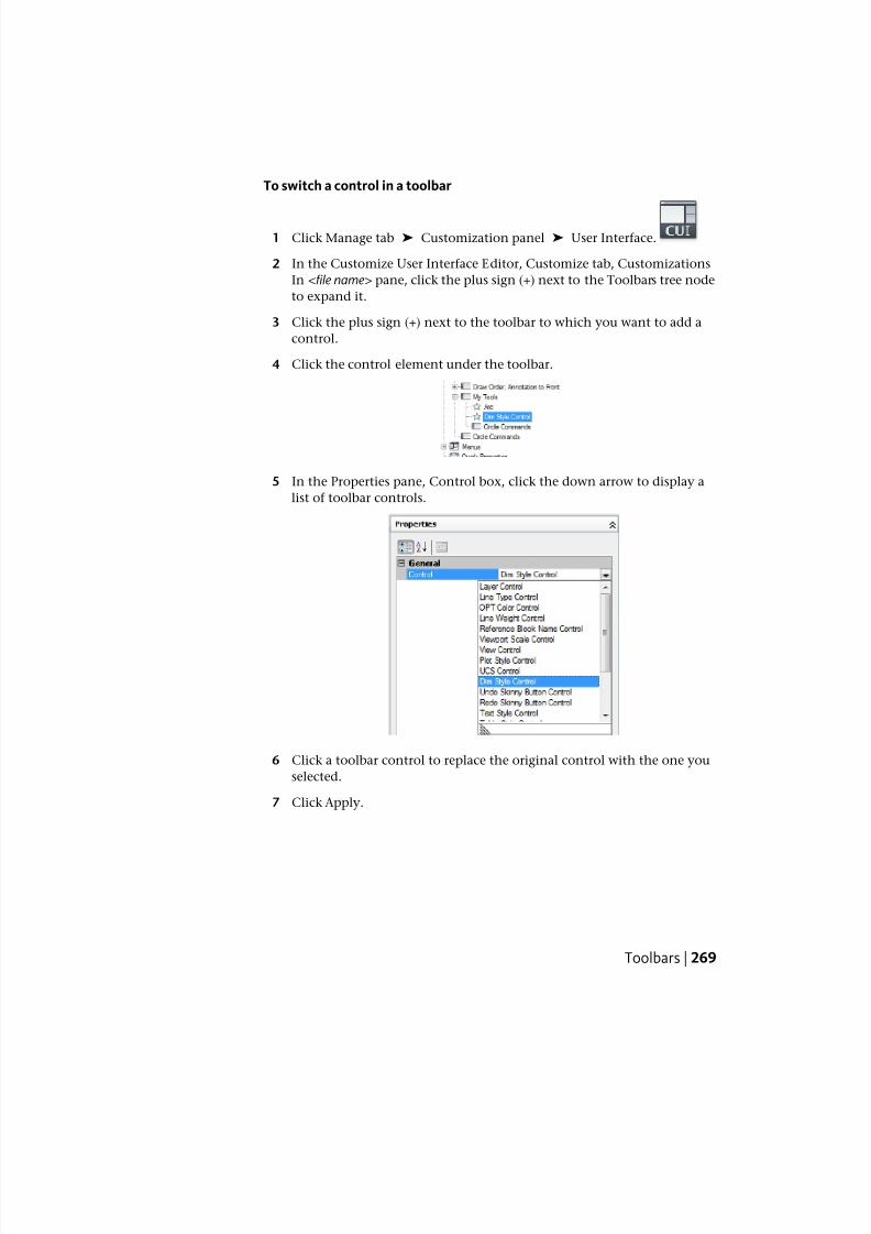
7/23/2019 Acad Customization
http://slidepdf.com/reader/full/acad-customization 277/553
To switch a control in a toolbar
1 Click Manage tab ➤ Customization panel ➤ User Interface.
2 In the Customize User Interface Editor, Customize tab, Customizations
In <file name> pane, click the plus sign (+) next to the Toolbars tree node
to expand it.
3 Click the plus sign (+) next to the toolbar to which you want to add a
control.
4 Click the control element under the toolbar.
5 In the Properties pane, Control box, click the down arrow to display a
list of toolbar controls.
6 Click a toolbar control to replace the original control with the one you
selected.
7 Click Apply.
Toolbars | 269
7/23/2019 Acad Customization
http://slidepdf.com/reader/full/acad-customization 278/553
Quick Reference
Commands
CUI
Manages the customized user interface elements in the product.
Pull-down and Shortcut MenusPull-down menus are displayed as a list under a menu bar. Shortcut menus
(also called context menus) are displayed at or near the crosshairs or cursor
when you right-click in the drawing window, text window, command window,
in toolbar areas, or the ribbon.
Overview of Pull-Down and Shortcut MenusA pull-down menu can contain up to 999 commands. A shortcut menu can
contain up to 499 commands. The command limit includes all menus in a
hierarchy. If commands in the menu file exceed these limits (which is unlikely),
the program ignores the extra commands. If a pull-down or shortcut menu is
longer than the available display space, it is truncated to fit. When a pull-down
or shortcut menu is truncated, two arrows are added to the menu; one is added
at the top and another to the bottom. With the arrows, you can scroll the list
of menu items up or down. The following table shows the properties for the
File menu as they appear in the Properties pane. The properties for a pull-down
menu and shortcut menu are identical.
Properties for the File menu
ExampleDescriptionProperties paneitem
&FileString used as the caption of the menu on the menu bar.Name
Text used to describe the element; does not appear in
the user interface.
Description
POP1, FILESpecifies the aliases for the menu. Click the [ ] button to
open the Aliases dialog box. Each alias in the CUIx file
Aliases
should be unique; and it is used to reference the menu
programmatically.
ID_MnFileTag that uniquely identifies a menu.Element ID
270 | Chapter 4 User Interface Customization
7/23/2019 Acad Customization
http://slidepdf.com/reader/full/acad-customization 279/553
NOTE When you create a pull-down or shortcut menu, you must also add at least
one command to the menu. Otherwise, the menu will not be displayed on the
menu bar.
Quick Reference
Commands
CUI
Manages the customized user interface elements in the product.
System Variables
MENUBAR
Controls the display of the menu bar.
Create a Pull-Down MenuYou can create a pull-down menu, add submenus and commands to it on the
Customize tab of the Customize User Interface (CUI) Editor.
You can create and modify standard pull-down menus to display and organize
the commands to best match the way you work. Commands are added to a
pull-down menu from the Command List pane. Once commands are added
to a pull-down menu, you can change the caption displayed for the command
on the menu, reposition commands, and organize commands using separators.
Along with separators, you can also group commands using submenus. For
more information on submenus, see Create Submenus on page 285.
As you modify the positioning of commands on menus, the online Help
system is automatically updated to reflect the change through the Dynamic
Help feature. For more information about how Dynamic Help affects
customization, see How Customization Has Changed on page 96.
NOTE When you create a menu, you should determine in which workspaces you
want to display the menu in. By default, a new menu is displayed in all workspaces.
Pull-Down Menu Aliases
Pull-down menus should have one alias in the range of POP1 through POP499.
Menus with an alias of POP1 through POP16 are loaded by default when a
menu loads. All other menus must be added to a workspace to be displayed.
Pull-down and Shortcut Menus | 271
7/23/2019 Acad Customization
http://slidepdf.com/reader/full/acad-customization 280/553
To create a pull-down menu
1 Click Manage tab ➤ Customization panel ➤ User Interface.
2 In the Customize User Interface Editor, Customize tab, in the
Customizations In <file name> pane, right-click Menus. Click New Menu.
A new menu (named Menu1) is placed at the bottom of the Menus tree.
3 Do one of the following:
■ Enter a new name over the default name Menu1.
■ Right-click Menu1. Click Rename. Enter a new menu name.
■ Click Menu1, wait, and click again over the menu’s name again to
edit its name in-place.
4 Select the new menu in the tree view, and update the Properties pane as
follows:
■ In the Description box, enter a description for the menu.
■ In the Aliases box, an alias is automatically assigned to the new menu,based on the number of menus already loaded. For example, if the
alias assignment is POP12, eleven menus are already loaded. View or
edit the alias.
■ (Optional) If the name change is based upon a DIESEL expression,
the DIESEL expression should be included in the Name box.
5 In the Command List pane, drag the command to a location just belowthe menu in the Customizations In <file name> pane.
272 | Chapter 4 User Interface Customization
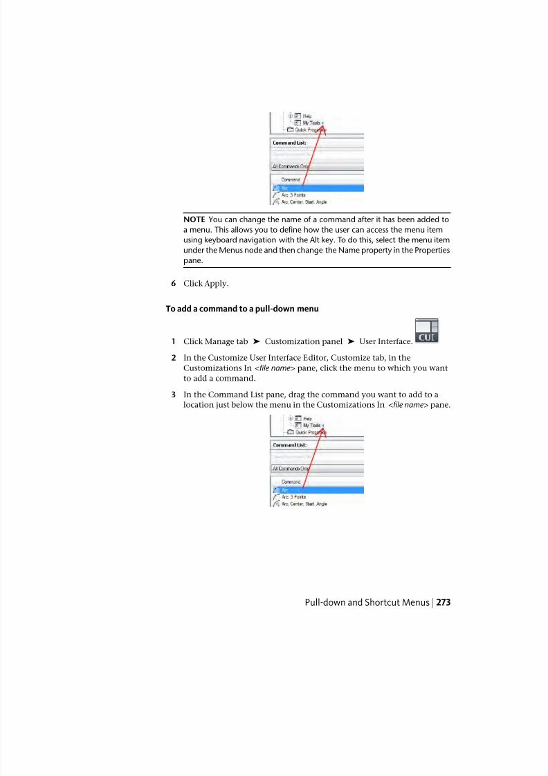
7/23/2019 Acad Customization
http://slidepdf.com/reader/full/acad-customization 281/553
NOTE You can change the name of a command after it has been added to
a menu. This allows you to define how the user can access the menu item
using keyboard navigation with the Alt key. To do this, select the menu item
under the Menus node and then change the Name property in the Properties
pane.
6 Click Apply.
To add a command to a pull-down menu
1 Click Manage tab ➤ Customization panel ➤ User Interface.
2 In the Customize User Interface Editor, Customize tab, in the
Customizations In <file name> pane, click the menu to which you want
to add a command.
3 In the Command List pane, drag the command you want to add to a
location just below the menu in the Customizations In <file name> pane.
Pull-down and Shortcut Menus | 273
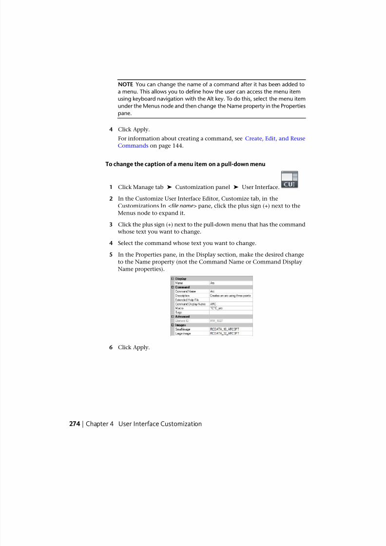
7/23/2019 Acad Customization
http://slidepdf.com/reader/full/acad-customization 282/553
NOTE You can change the name of a command after it has been added to
a menu. This allows you to define how the user can access the menu item
using keyboard navigation with the Alt key. To do this, select the menu item
under the Menus node and then change the Name property in the Properties
pane.
4 Click Apply.
For information about creating a command, see Create, Edit, and Reuse
Commands on page 144.
To change the caption of a menu item on a pull-down menu
1 Click Manage tab ➤ Customization panel ➤ User Interface.
2 In the Customize User Interface Editor, Customize tab, in the
Customizations In <file name> pane, click the plus sign (+) next to the
Menus node to expand it.
3 Click the plus sign (+) next to the pull-down menu that has the command
whose text you want to change.
4 Select the command whose text you want to change.
5 In the Properties pane, in the Display section, make the desired change
to the Name property (not the Command Name or Command Display
Name properties).
6 Click Apply.
274 | Chapter 4 User Interface Customization
7/23/2019 Acad Customization
http://slidepdf.com/reader/full/acad-customization 283/553
Quick Reference
Commands
CUI
Manages the customized user interface elements in the product.
System Variables
MENUBAR
Controls the display of the menu bar.
Create a Shortcut Menu
Shortcut menus are displayed at or near the location of your cursor when youright-click on the pointing device. The shortcut menu and the options it
provides depend on the location of the cursor and other conditions, such as
whether an object is selected or a command is in progress.
Context-sensitive shortcut menus display menu options that are relative to the
current command or the selected object when you right-click.
Shortcut Menu Aliases
Shortcut menus are referenced by their aliases and are used in specific
situations. In the Customize User Interface (CUI) Editor, the alias names must
follow the proper naming conventions. For example, the shortcut menu named
“Default Menu” displays the following information in the Aliases section of
the Properties pane:
POP501, CMDEFAULT
CMDEFAULT is one of the reserved aliases that the program looks for in specific
situations. In this case, the shortcut menu assigned the alias CMDEFAULT is
displayed if no objects are selected and no command is in progress when you
right-click over the drawing window.
Pull-down and Shortcut Menus | 275
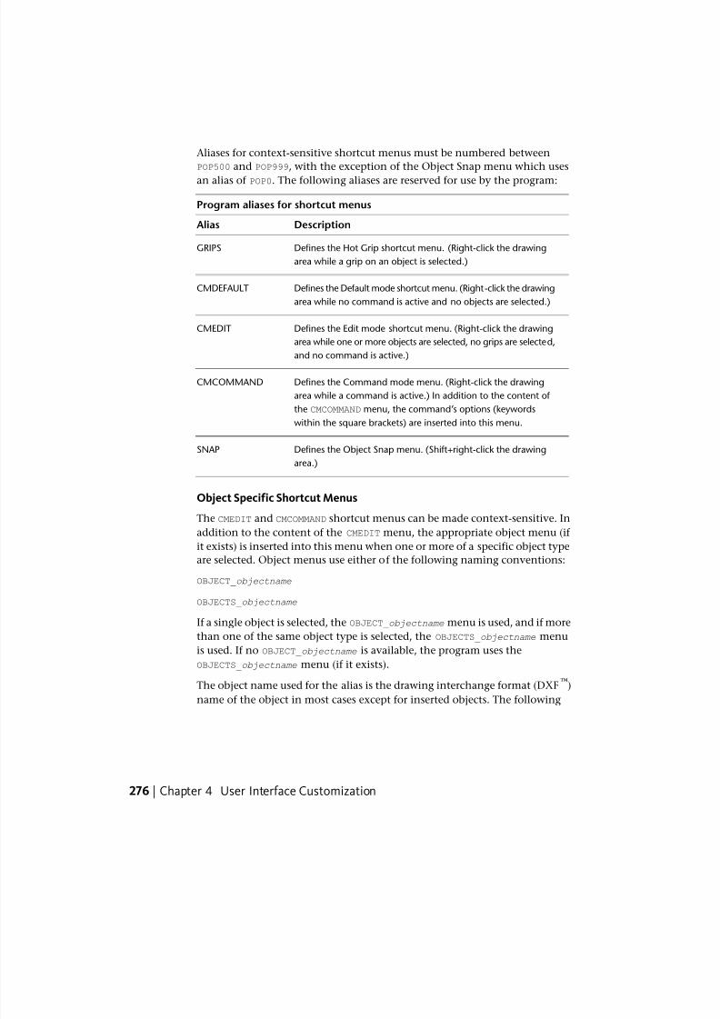
7/23/2019 Acad Customization
http://slidepdf.com/reader/full/acad-customization 284/553
Aliases for context-sensitive shortcut menus must be numbered between
POP500 and POP999, with the exception of the Object Snap menu which uses
an alias of POP0. The following aliases are reserved for use by the program:
Program aliases for shortcut menus
DescriptionAlias
Defines the Hot Grip shortcut menu. (Right-click the drawing
area while a grip on an object is selected.)
GRIPS
Defines the Default mode shortcut menu. (Right-click the drawing
area while no command is active and no objects are selected.)
CMDEFAULT
Defines the Edit mode shortcut menu. (Right-click the drawing
area while one or more objects are selected, no grips are selected,
and no command is active.)
CMEDIT
Defines the Command mode menu. (Right-click the drawing
area while a command is active.) In addition to the content of
CMCOMMAND
the CMCOMMAND menu, the command’s options (keywords
within the square brackets) are inserted into this menu.
Defines the Object Snap menu. (Shift+right-click the drawing
area.)
SNAP
Object Specific Shortcut Menus
The CMEDIT and CMCOMMAND shortcut menus can be made context-sensitive. In
addition to the content of the CMEDIT menu, the appropriate object menu (if it exists) is inserted into this menu when one or more of a specific object type
are selected. Object menus use either of the following naming conventions:
OBJECT_objectname
OBJECTS_objectname
If a single object is selected, the OBJECT_objectname menu is used, and if more
than one of the same object type is selected, the OBJECTS_objectname menu
is used. If no OBJECT_objectname is available, the program uses the
OBJECTS_objectname menu (if it exists).
The object name used for the alias is the drawing interchange format (DXF™
)
name of the object in most cases except for inserted objects. The following
276 | Chapter 4 User Interface Customization

7/23/2019 Acad Customization
http://slidepdf.com/reader/full/acad-customization 285/553
table shows the object names that are specific to inserted objects (blocks,
dynamic blocks, and xrefs).
Object names specific to insert objects
DescriptionObject Name
Block reference with attributes ATTBLOCKREF
Dynamic block reference with attributes ATTDYNBLOCKREF
Block reference without attributesBLOCKREF
Dynamic block reference without attributesDYNBLOCKREF
External reference (xref)XREF
For example, to support an object-specific shortcut menu for one or more
selected block references, you would create or modify a shortcut menu and
change its properties to those in the following table. The important property
to change is Aliases, which would need to modified to include the alias
OBJECTS_BLOCKREF.
Properties for the Block Reference Objects shortcut menu
ExampleDescriptionPropertiespane item
Block Objects MenuString that is only used in the CUI Editor and is
not displayed in the user interface.
Name
Shortcut menu for
block objects
Text used to describe the element; does not
appear in the user interface.
Descrip-
tion
POP512,OB-
JECTS_BLOCKREF
Specifies the aliases for the shortcut menu. Click
the [ ] button to open the Aliases dialog box.
Aliases
Each alias in the CUIx file should be unique and
it is used to reference the shortcut menu pro-
grammatically.
PM_0021Tag that uniquely identifies a shortcut menu.Element ID
Pull-down and Shortcut Menus | 277
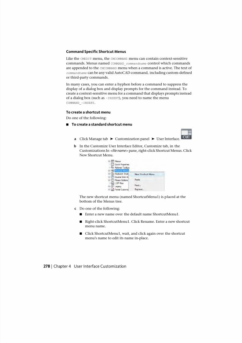
7/23/2019 Acad Customization
http://slidepdf.com/reader/full/acad-customization 286/553
Command Specific Shortcut Menus
Like the CMEDIT menu, the CMCOMMAND menu can contain context-sensitivecommands. Menus named COMMAND_commandname control which commands
are appended to the CMCOMMAND menu when a command is active. The text of
commandname can be any valid AutoCAD command, including custom-defined
or third-party commands.
In many cases, you can enter a hyphen before a command to suppress the
display of a dialog box and display prompts for the command instead. To
create a context-sensitive menu for a command that displays prompts instead
of a dialog box (such as -INSERT), you need to name the menu
COMMAND_-INSERT.
To create a shortcut menu
Do one of the following:
■ To create a standard shortcut menu
a Click Manage tab ➤ Customization panel ➤ User Interface.
b In the Customize User Interface Editor, Customize tab, in the
Customizations In <file name> pane, right-click Shortcut Menus. Click
New Shortcut Menu.
The new shortcut menu (named ShortcutMenu1) is placed at the
bottom of the Menus tree.
c Do one of the following:
■ Enter a new name over the default name ShortcutMenu1.
■ Right-click ShortcutMenu1. Click Rename. Enter a new shortcut
menu name.
■ Click ShortcutMenu1, wait, and click again over the shortcut
menu’s name to edit its name in-place.
278 | Chapter 4 User Interface Customization
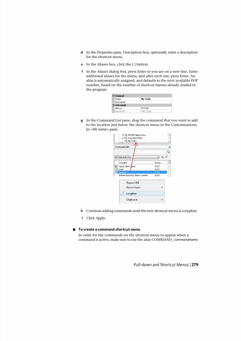
7/23/2019 Acad Customization
http://slidepdf.com/reader/full/acad-customization 287/553
d In the Properties pane, Description box, optionally enter a description
for the shortcut menu.
e In the Aliases box, click the [ ] button.
f In the Aliases dialog box, press Enter so you are on a new line. Enter
additional aliases for the menu, and after each one, press Enter. An
alias is automatically assigned, and defaults to the next available POP
number, based on the number of shortcut menus already loaded in
the program.
g In the Command List pane, drag the command that you want to addto the location just below the shortcut menu in the Customizations
In <file name> pane.
h Continue adding commands until the new shortcut menu is complete.
i Click Apply.
■ To create a command shortcut menu
In order for the commands on the shortcut menu to appear when a
command is active, make sure to use the alias COMMAND_commandname .
Pull-down and Shortcut Menus | 279
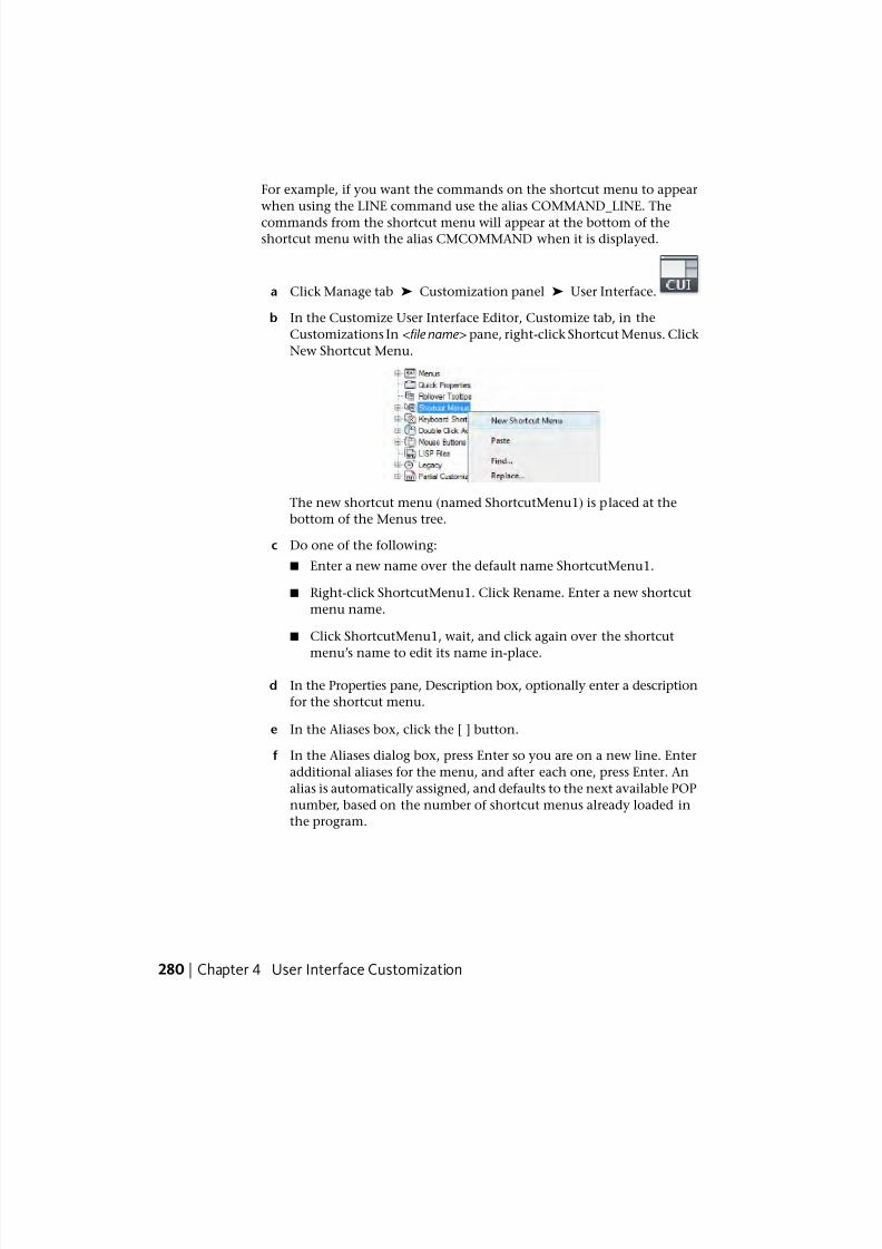
7/23/2019 Acad Customization
http://slidepdf.com/reader/full/acad-customization 288/553
For example, if you want the commands on the shortcut menu to appear
when using the LINE command use the alias COMMAND_LINE. The
commands from the shortcut menu will appear at the bottom of theshortcut menu with the alias CMCOMMAND when it is displayed.
a Click Manage tab ➤ Customization panel ➤ User Interface.
b In the Customize User Interface Editor, Customize tab, in the
Customizations In <file name> pane, right-click Shortcut Menus. Click
New Shortcut Menu.
The new shortcut menu (named ShortcutMenu1) is placed at the
bottom of the Menus tree.
c Do one of the following:
■ Enter a new name over the default name ShortcutMenu1.
■ Right-click ShortcutMenu1. Click Rename. Enter a new shortcut
menu name.
■ Click ShortcutMenu1, wait, and click again over the shortcut
menu’s name to edit its name in-place.
d In the Properties pane, Description box, optionally enter a description
for the shortcut menu.
e In the Aliases box, click the [ ] button.
f In the Aliases dialog box, press Enter so you are on a new line. Enter
additional aliases for the menu, and after each one, press Enter. An
alias is automatically assigned, and defaults to the next available POP
number, based on the number of shortcut menus already loaded in
the program.
280 | Chapter 4 User Interface Customization
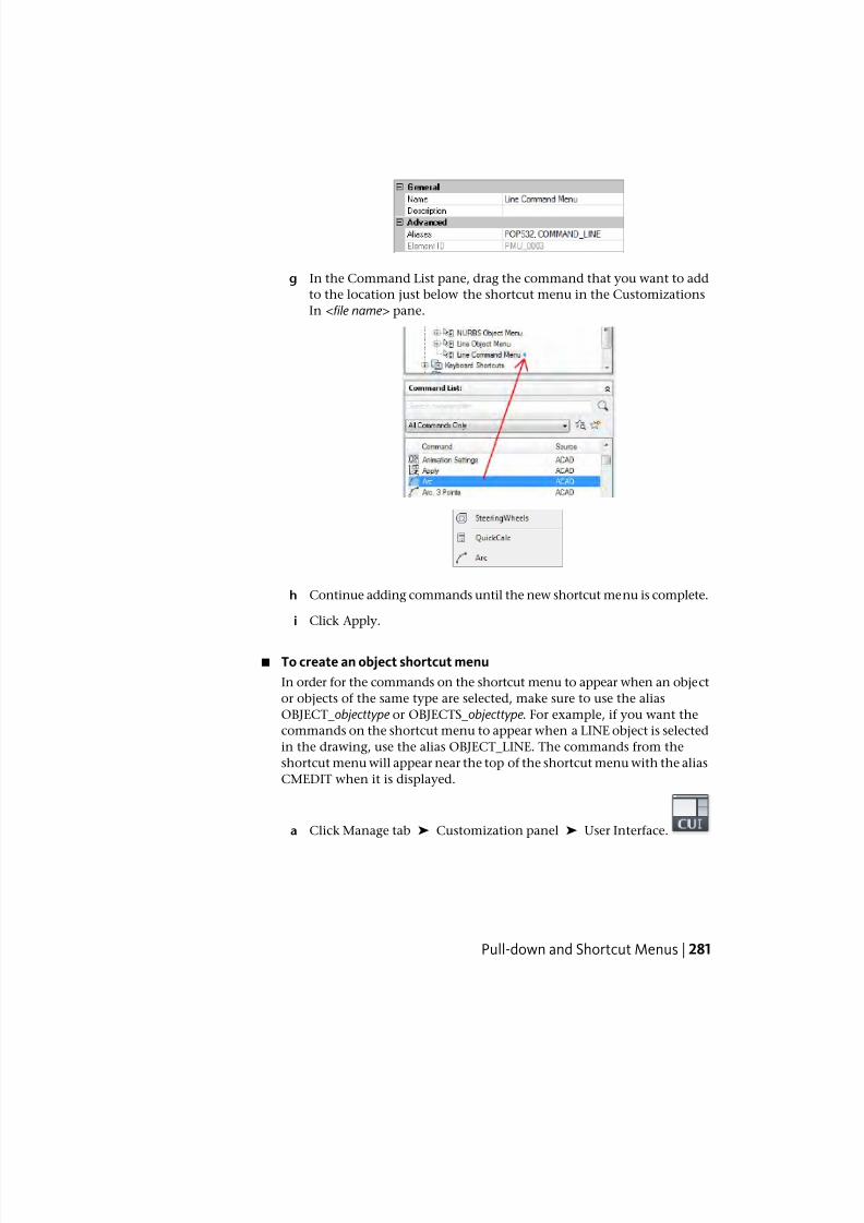
7/23/2019 Acad Customization
http://slidepdf.com/reader/full/acad-customization 289/553
g In the Command List pane, drag the command that you want to add
to the location just below the shortcut menu in the Customizations
In <file name> pane.
h Continue adding commands until the new shortcut menu is complete.
i Click Apply.
■ To create an object shortcut menu
In order for the commands on the shortcut menu to appear when an object
or objects of the same type are selected, make sure to use the alias
OBJECT_objecttype or OBJECTS_objecttype . For example, if you want the
commands on the shortcut menu to appear when a LINE object is selected
in the drawing, use the alias OBJECT_LINE. The commands from the
shortcut menu will appear near the top of the shortcut menu with the alias
CMEDIT when it is displayed.
a Click Manage tab ➤ Customization panel ➤ User Interface.
Pull-down and Shortcut Menus | 281
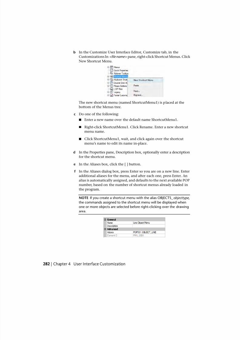
7/23/2019 Acad Customization
http://slidepdf.com/reader/full/acad-customization 290/553
b In the Customize User Interface Editor, Customize tab, in the
Customizations In <file name> pane, right-click Shortcut Menus. Click
New Shortcut Menu.
The new shortcut menu (named ShortcutMenu1) is placed at the
bottom of the Menus tree.
c Do one of the following:
■ Enter a new name over the default name ShortcutMenu1.
■ Right-click ShortcutMenu1. Click Rename. Enter a new shortcut
menu name.
■ Click ShortcutMenu1, wait, and click again over the shortcut
menu’s name to edit its name in-place.
d In the Properties pane, Description box, optionally enter a description
for the shortcut menu.
e In the Aliases box, click the [ ] button.
f In the Aliases dialog box, press Enter so you are on a new line. Enter
additional aliases for the menu, and after each one, press Enter. An
alias is automatically assigned, and defaults to the next available POP
number, based on the number of shortcut menus already loaded in
the program.
NOTE If you create a shortcut menu with the alias OBJECTS_objecttype ,
the commands assigned to the shortcut menu will be displayed when
one or more objects are selected before right-clicking over the drawing
area.
282 | Chapter 4 User Interface Customization
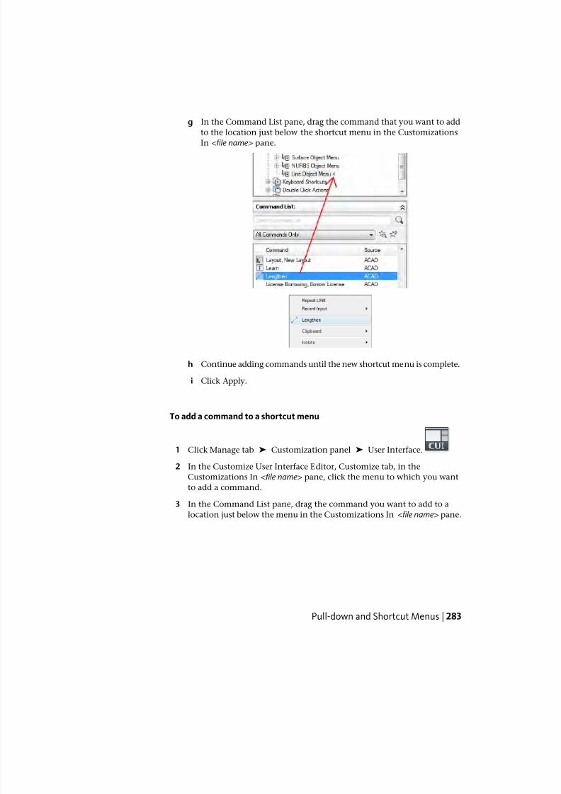
7/23/2019 Acad Customization
http://slidepdf.com/reader/full/acad-customization 291/553
g In the Command List pane, drag the command that you want to add
to the location just below the shortcut menu in the Customizations
In <file name> pane.
h Continue adding commands until the new shortcut menu is complete.
i Click Apply.
To add a command to a shortcut menu
1 Click Manage tab ➤ Customization panel ➤ User Interface.
2 In the Customize User Interface Editor, Customize tab, in the
Customizations In <file name> pane, click the menu to which you want
to add a command.
3 In the Command List pane, drag the command you want to add to a
location just below the menu in the Customizations In <file name> pane.
Pull-down and Shortcut Menus | 283
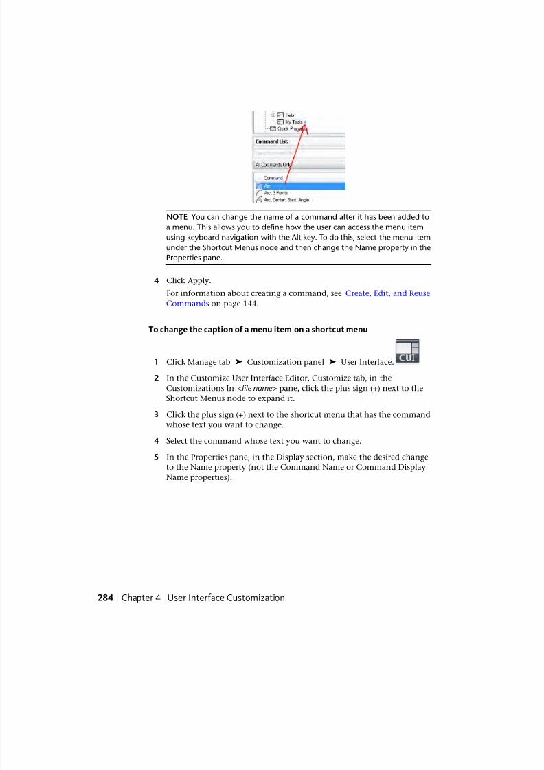
7/23/2019 Acad Customization
http://slidepdf.com/reader/full/acad-customization 292/553
NOTE You can change the name of a command after it has been added to
a menu. This allows you to define how the user can access the menu item
using keyboard navigation with the Alt key. To do this, select the menu item
under the Shortcut Menus node and then change the Name property in the
Properties pane.
4 Click Apply.
For information about creating a command, see Create, Edit, and Reuse
Commands on page 144.
To change the caption of a menu item on a shortcut menu
1 Click Manage tab ➤ Customization panel ➤ User Interface.
2 In the Customize User Interface Editor, Customize tab, in the
Customizations In <file name> pane, click the plus sign (+) next to the
Shortcut Menus node to expand it.
3 Click the plus sign (+) next to the shortcut menu that has the command
whose text you want to change.
4 Select the command whose text you want to change.
5 In the Properties pane, in the Display section, make the desired change
to the Name property (not the Command Name or Command Display
Name properties).
284 | Chapter 4 User Interface Customization
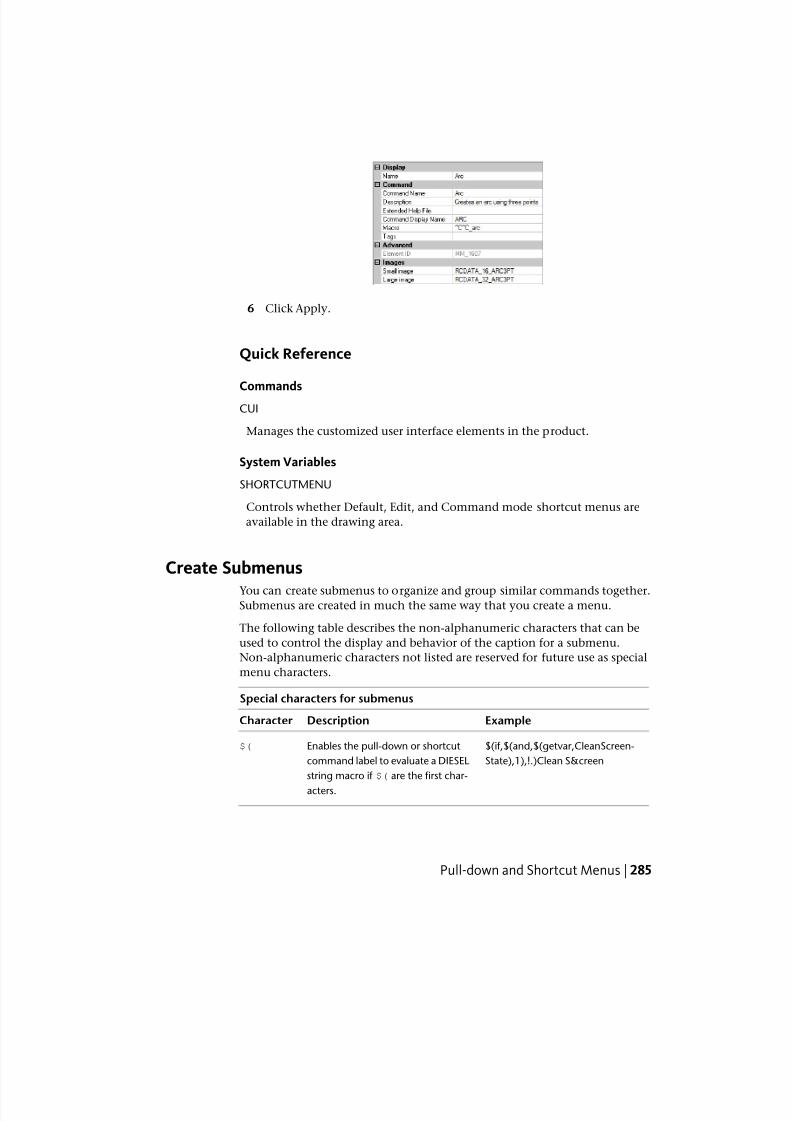
7/23/2019 Acad Customization
http://slidepdf.com/reader/full/acad-customization 293/553
6 Click Apply.
Quick Reference
CommandsCUI
Manages the customized user interface elements in the product.
System Variables
SHORTCUTMENU
Controls whether Default, Edit, and Command mode shortcut menus are
available in the drawing area.
Create Submenus
You can create submenus to organize and group similar commands together.Submenus are created in much the same way that you create a menu.
The following table describes the non-alphanumeric characters that can be
used to control the display and behavior of the caption for a submenu.
Non-alphanumeric characters not listed are reserved for future use as special
menu characters.
Special characters for submenus
ExampleDescriptionCharacter
$(if,$(and,$(getvar,CleanScreen-
State),1),!.)Clean S&creen
Enables the pull-down or shortcut
command label to evaluate a DIESEL
$(
string macro if $( are the first char-
acters.
Pull-down and Shortcut Menus | 285
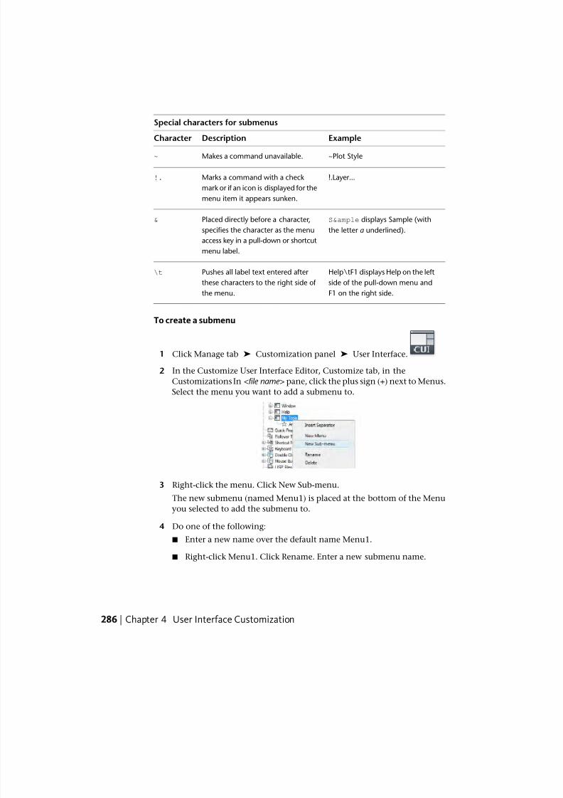
7/23/2019 Acad Customization
http://slidepdf.com/reader/full/acad-customization 294/553
Special characters for submenus
ExampleDescriptionCharacter
~Plot StyleMakes a command unavailable.~
!.Layer...Marks a command with a check
mark or if an icon is displayed for the
menu item it appears sunken.
!.
S&le displays Sample (with
the letter a underlined).
Placed directly before a character,
specifies the character as the menu
access key in a pull-down or shortcut
menu label.
&
Help\tF1 displays Help on the left
side of the pull-down menu and
F1 on the right side.
Pushes all label text entered after
these characters to the right side of
the menu.
\t
To create a submenu
1 Click Manage tab ➤ Customization panel ➤ User Interface.
2 In the Customize User Interface Editor, Customize tab, in the
Customizations In <file name> pane, click the plus sign (+) next to Menus.
Select the menu you want to add a submenu to.
3 Right-click the menu. Click New Sub-menu.
The new submenu (named Menu1) is placed at the bottom of the Menu
you selected to add the submenu to.
4 Do one of the following:
■ Enter a new name over the default name Menu1.
■ Right-click Menu1. Click Rename. Enter a new submenu name.
286 | Chapter 4 User Interface Customization
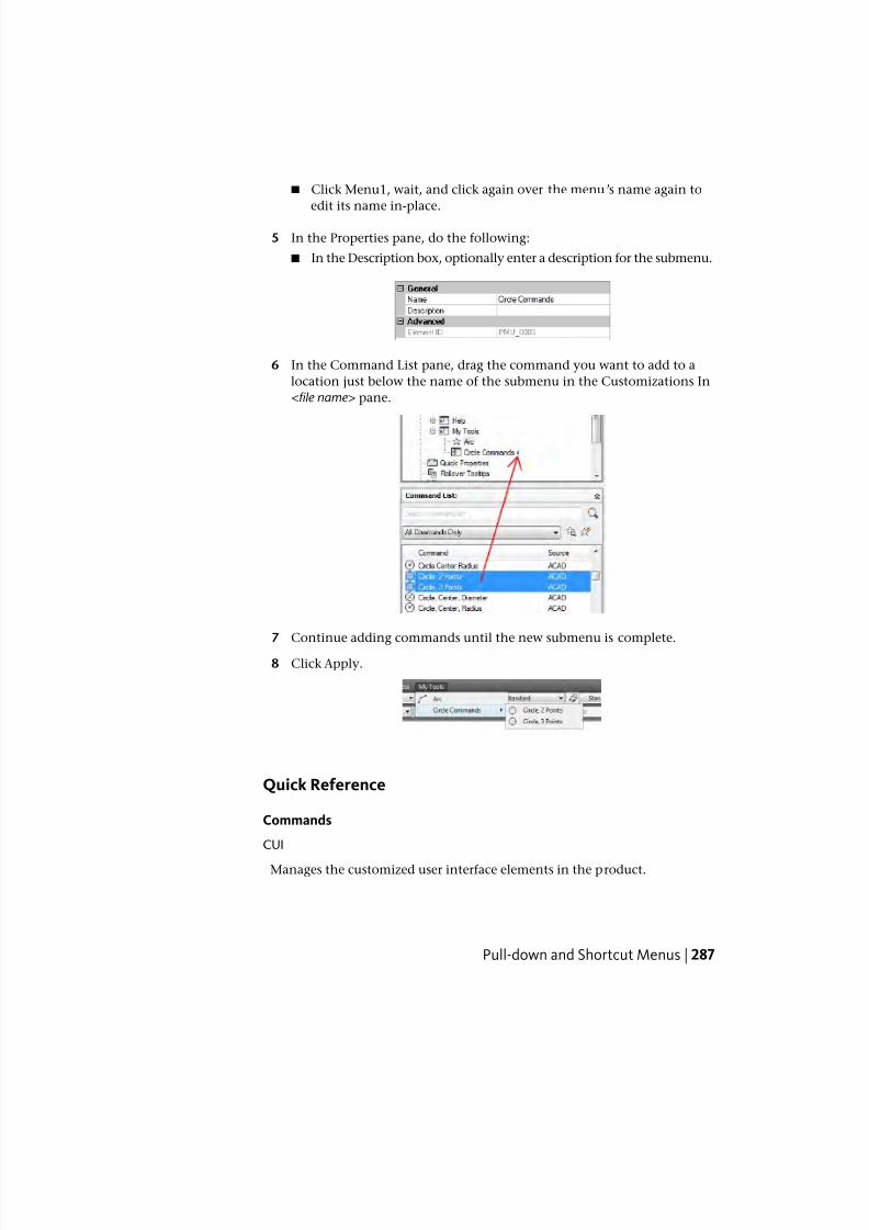
7/23/2019 Acad Customization
http://slidepdf.com/reader/full/acad-customization 295/553
■ Click Menu1, wait, and click again over the menu’s name again to
edit its name in-place.
5 In the Properties pane, do the following:
■ In the Description box, optionally enter a description for the submenu.
6 In the Command List pane, drag the command you want to add to a
location just below the name of the submenu in the Customizations In
<file name> pane.
7 Continue adding commands until the new submenu is complete.
8 Click Apply.
Quick Reference
Commands
CUI
Manages the customized user interface elements in the product.
Pull-down and Shortcut Menus | 287
7/23/2019 Acad Customization
http://slidepdf.com/reader/full/acad-customization 296/553
Reference Pull-Down or Shortcut Menus
Using a method similar to that used to activate submenus, you can activateor deactivate another pull-down or shortcut menu. This is called menu
referencing .
Pull-down or shortcut menus can be referenced using two different methods:
relative and absolute . Relative referencing uses the customization group name
and element ID. Absolute referencing uses the absolute position of a menu
item in the menu hierarchy. Relative referencing is recommended because of
its dynamic nature, which allows it to function regardless of the current state
of a menu.
Relative Referencing of Pull-Down and Shortcut Commands
To reference a pull-down or shortcut menu item based on its customization
group and element ID, use the AutoLISP menucmd function. The followingsyntax references a menu item based on its element ID.
(menucmd "Gcustomizationgroup .element_id =value")
The following example uses the relative referencing syntax to disable the menu
item ID_Line that is stored in the ACAD customization group. It works regardless
of the menu item's location in the menu.
(menucmd "GACAD.ID_Line=~")
If you know what is contained in the main CUIx file, you can create a partial
CUIx file with an additional menu item that references the main file. In this
manner, partial CUIx files and specific base files can work together.
Absolute Referencing of Pull-Down and Shortcut Menu ItemsIn addition to referencing a menu item, you can activate or deactivate a menu
item with the $Pn=xxx syntax. This is the format:
$Pn.i=xxx
The $ loads a menu section; Pn specifies the active menu section (0 through
16 are valid values); i specifies the menu item number; and xxx (if present),
specifies a string of grayed out or marked characters.
Using the $Pn=xxx syntax, the following example adds a check mark to item
1 in the POP7 section.
$P7.1=!.
The following example uses the AutoLISP menucmd function to reference apull-down or shortcut menu item. Because customization files are dynamic
288 | Chapter 4 User Interface Customization
7/23/2019 Acad Customization
http://slidepdf.com/reader/full/acad-customization 297/553
(through the loading of partial CUIx files), the following syntax will not work
in all cases.
(menucmd "P1.2=~")
This syntax relies on the location of the menu item and does not work if a
new item is inserted before POP1 by the CUILOAD command.
Menu item numbering is consecutive regardless of the hierarchy of the menu.
To make it easy for an item to address itself regardless of its location in the
menu hierarchy, use these forms:
$P@.@=xxx References the current or most recently chosen command.
[email protected]=xxx References item n in the current or most recently chosen menu.
AutoLISP Access to Label Status
The AutoLISP menucmd function accepts $Pn=xxx command strings but without
the leading $. For these functions, the xxx portion of the command string can
have special values.
Pn.i=? Returns the current disabled and marked status for the specified item
as a string (for example, ~ for a disabled item, !. for an item with a check
mark, and "" for an item that is neither grayed out nor marked).
Pn.i=#? Returns the same type of string as described for Pn.i=?, but with the
Pn.i= prefix. This is useful in conjunction with the @ forms, because the actual
menu and item number are returned.
For example, if the fifth item in the POP6 section is disabled, the following
menucmd code returns the following string values.
(menucmd "P6.5=?") returns "~"
(menucmd "P6.5=#?") returns "P6.5=~"
See “Use of AutoLISP in Macros” in the AutoLISP Developer's Guide .
Quick Reference
Commands
CUI
Manages the customized user interface elements in the product.
Pull-down and Shortcut Menus | 289
7/23/2019 Acad Customization
http://slidepdf.com/reader/full/acad-customization 298/553
Swap and Insert Pull-Down Menus
Using the Customize User Interface (CUI) Editor, you can use workspaces tocontrol the swapping of pull-down menus. However, you can also swap one
pull-down menu programmatically for another (for example, when a user
loads an application that requires an additional menu).
Swap Pull-Down Menus
Because the program has cascading pull-down menus, there is little need to
swap menus. Also, swapping menus can detract from the consistency of the
user interface. However, using $ commands, you can swap pull-down menus
and submenus. An alternative to menu swapping involves relative (or global)
referencing. Using this method, you can insert the new menu in front of a
known menu and then remove the known menu.
For menu-swapping purposes, the pull-down menu areas are named P1 throughP16. You can change the title that appears in the menu bar by replacing that
line of the menu with a $Pn= command. You can use the special command
$Pn=* from within any command to force the menu currently assigned to area
POPn to pull down for greater flexibility in movement of the pointing device.
The following macro example replaces a menu at position P3 with the menu
named MyMenu in the customization group named MYMENU.
$P3=mymenu.new3
The same thing can be done with the AutoLISP menucmd function as follows:
(menucmd "P3=mymenu.new3")
You can use the$P
n=*
special command from within any macro to force themenu currently assigned to area POPn to be displayed.
NOTE The swapping of pull-down menus does not conform to the Microsoft®
user interface guidelines and is not guaranteed to be available in future releases
of the program.
Insert and Remove Pull-Down Menus
Menu swapping is done by activating one menu directly from another menu.
Menu swapping is supported for the following interface elements:
■ B - Buttons
■ P - Pull-down menus
290 | Chapter 4 User Interface Customization
7/23/2019 Acad Customization
http://slidepdf.com/reader/full/acad-customization 299/553
■ A - Mouse buttons
■ I - Image tile menus
■ T - Tablet menus
The syntax for the swapping of partial menus is as follows:
$section=customizationgroup.menuname
section
B1-4, A1-4, P0-16, T1-4
customizationgroup
Customization group name in the desired CUIx file
menunameMain label or alias
You can use the AutoLISP menucmd function to insert or remove a pull-down
menu. The syntax is similar to that used to swap pull-down menus except
that the left side of the assignment is the pull-down menu before which the
new menu will be inserted. The right side of the assignment is a plus sign (+)
followed by the name of the menu group, a period, and the menu's alias, as
shown in the following syntax:
(menucmd "customizationgroup1.menuname1=+customizationgroup2.menun
ame2")
You can also insert a menu with the Pn= syntax. The following macro inserts
a menu after the P5 menu.
(menucmd "P5=+mymenu.new3")
$P5=+mymenu.new3
If you use this method to insert a menu, remember that you cannot rely on
its being inserted at the P6 menu location as you might expect. There are two
reasons that this may not be the case.
■ If the current menu bar has only three menus, inserting a menu after menu
P5 results in the new menu's location being P4.
■ If the user inserts or removes a customization file with the CUILOAD
command or when another application inserts or removes customization
files, menu numbering can get out of sync.
Pull-down and Shortcut Menus | 291
7/23/2019 Acad Customization
http://slidepdf.com/reader/full/acad-customization 300/553
This is the syntax for removing a menu:
(menucmd "Gcustomizationgroup .menuname=-")Gcustomizationgroup .menuname=-
The following shows how to remove the menu NEW3 that is a member of the
MyMenu group.
(menucmd "Gmymenu.new3=-")
$Gmymenu.new3=-"
As you might expect, the preceding format is preferable to the Pn= format
because it removes only the specified menu. The following shows how to
remove the menu at the P4 location (whatever it is).
(menucmd "P4=-")
$P4=-
NOTE Use the Pn syntax as part of the syntax for a menucmd statement only. Use
the $Pn syntax for macro-specific statements.
Control Toolbars Across Partial CUIx Files
To control toolbars across partial CUIx files, use the following syntax at the
Enter toolbar name or [ALL]: prompt of the -TOOLBAR command.
menugroup.subsection-name
This syntax accesses the toolbar identified by menugroup.menuname and allows
you to use the full spectrum of -TOOLBAR command options on that toolbar.
If the menu group is left out of any of these commands and functions, the
program defaults to the main CUIx file.You should be aware of the following:
■ Image tile menus cannot be swapped from external customization files.
■ You can swap customization elements of the same type only; that is, one
shortcut menu for another, one toolbar for another, and so on. Trying to
swap between types may result in unpredictable behavior.
292 | Chapter 4 User Interface Customization
7/23/2019 Acad Customization
http://slidepdf.com/reader/full/acad-customization 301/553
Quick Reference
Commands
CUI
Manages the customized user interface elements in the product.
CUILOAD
Loads a CUIx file.
CUIUNLOAD
Unloads a CUIx file.
-TOOLBAR
Displays, hides, and customizes toolbars.
WORKSPACE
Creates, modifies, and saves workspaces and makes a workspace current.
Quick PropertiesWith the Quick Properties palette, for a selected object, you can access a sub-set
of the properties that are accessible from the Properties palette.
You can customize the properties that are displayed on the Quick Properties
palette. The properties (displayed when an object is selected) are common to
all object types and are specific to the object that was selected. The available
properties are the same as those on the Properties palette and for rollover
tooltips.
NOTE You can synchronize the properties that are displayed on the Quick
Properties palette with those for rollover tooltips.
Display Objects Properties on the Quick Properties Palette
When customizing the Quick Properties palette, you control which object
types display properties on the Quick Properties palette and which properties
are displayed. You use the Objects pane to add and remove the object types
that are set to display properties on the Quick Properties palette. Once an
object type is added to the Objects pane, you can then decide which properties
to display when on object of that type is selected in the drawing window.
Quick Properties | 293
7/23/2019 Acad Customization
http://slidepdf.com/reader/full/acad-customization 302/553
You can change the general properties for a selected object type or for all
object types. Selecting an object type from the Objects pane allows you to
control the display of the general properties for the selected object type, orby clicking the General button at the bottom of the Objects pane you can
override the general properties of all object types.
When the General button at the bottom of the Objects pane is clicked, a list
of the general properties that can be used to override the general properties
of all object types is displayed along with the Reset Overrides button. Selecting
the general properties that you want to display for all object types and clicking
Reset Overrides applies the selected general properties to all listed object types
in the Objects pane. However, after applying a general property to all object
types you can deselect any general property for a specific object type by
selecting the object type and deselecting the property.
Display the Quick Properties Palette
The Quick Properties palette is displayed when objects are selected, if the
object type of the selected objects is supported for Quick Properties, and if the
QPMODE system variable is set to 1 or 2. See Display and Change the Properties
of Objects in the User ’ s Guide for more information about controlling the
display of the Quick Properties.
NOTE When the system variable QPMODE is set to a value of 1, the general
properties that are checked are displayed in the Quick Properties palette for all
object types that are not in the list on the Objects pane.
To control which object types are used with the Quick Properties palette
1 Click Manage tab ➤ Customization panel ➤ User Interface.
2 In the Customize User Interface Editor, Customize tab, in the
Customizations In <file name> pane, select Quick Properties.
294 | Chapter 4 User Interface Customization
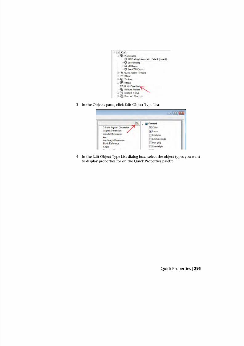
7/23/2019 Acad Customization
http://slidepdf.com/reader/full/acad-customization 303/553
3 In the Objects pane, click Edit Object Type List.
4 In the Edit Object Type List dialog box, select the object types you want
to display properties for on the Quick Properties palette.
Quick Properties | 295
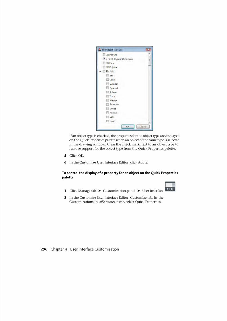
7/23/2019 Acad Customization
http://slidepdf.com/reader/full/acad-customization 304/553
If an object type is checked, the properties for the object type are displayed
on the Quick Properties palette when an object of the same type is selected
in the drawing window. Clear the check mark next to an object type to
remove support for the object type from the Quick Properties palette.
5 Click OK.
6 In the Customize User Interface Editor, click Apply.
To control the display of a property for an object on the Quick Propertiespalette
1 Click Manage tab ➤ Customization panel ➤ User Interface.
2 In the Customize User Interface Editor, Customize tab, in the
Customizations In <file name> pane, select Quick Properties.
296 | Chapter 4 User Interface Customization
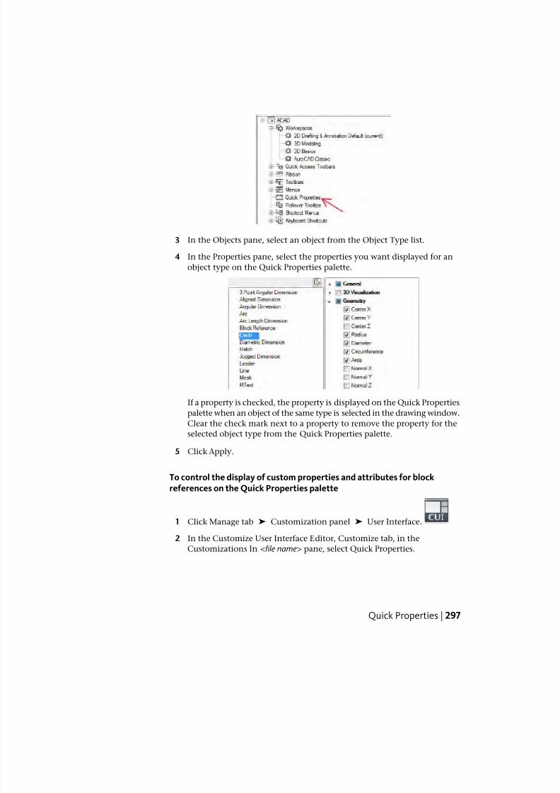
7/23/2019 Acad Customization
http://slidepdf.com/reader/full/acad-customization 305/553
3 In the Objects pane, select an object from the Object Type list.
4 In the Properties pane, select the properties you want displayed for an
object type on the Quick Properties palette.
If a property is checked, the property is displayed on the Quick Properties
palette when an object of the same type is selected in the drawing window.Clear the check mark next to a property to remove the property for the
selected object type from the Quick Properties palette.
5 Click Apply.
To control the display of custom properties and attributes for blockreferences on the Quick Properties palette
1 Click Manage tab ➤ Customization panel ➤ User Interface.
2 In the Customize User Interface Editor, Customize tab, in the
Customizations In <file name> pane, select Quick Properties.
Quick Properties | 297
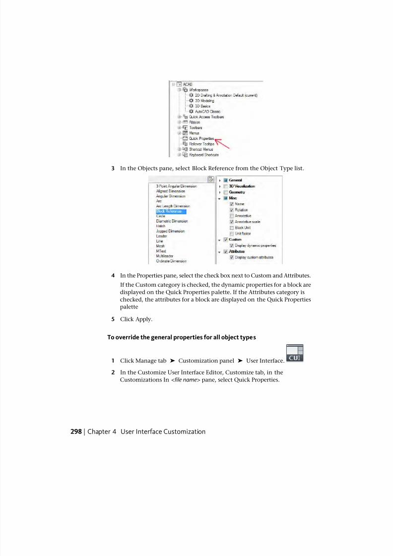
7/23/2019 Acad Customization
http://slidepdf.com/reader/full/acad-customization 306/553
3 In the Objects pane, select Block Reference from the Object Type list.
4 In the Properties pane, select the check box next to Custom and Attributes.
If the Custom category is checked, the dynamic properties for a block are
displayed on the Quick Properties palette. If the Attributes category ischecked, the attributes for a block are displayed on the Quick Properties
palette
5 Click Apply.
To override the general properties for all object types
1 Click Manage tab ➤ Customization panel ➤ User Interface.
2 In the Customize User Interface Editor, Customize tab, in the
Customizations In <file name> pane, select Quick Properties.
298 | Chapter 4 User Interface Customization
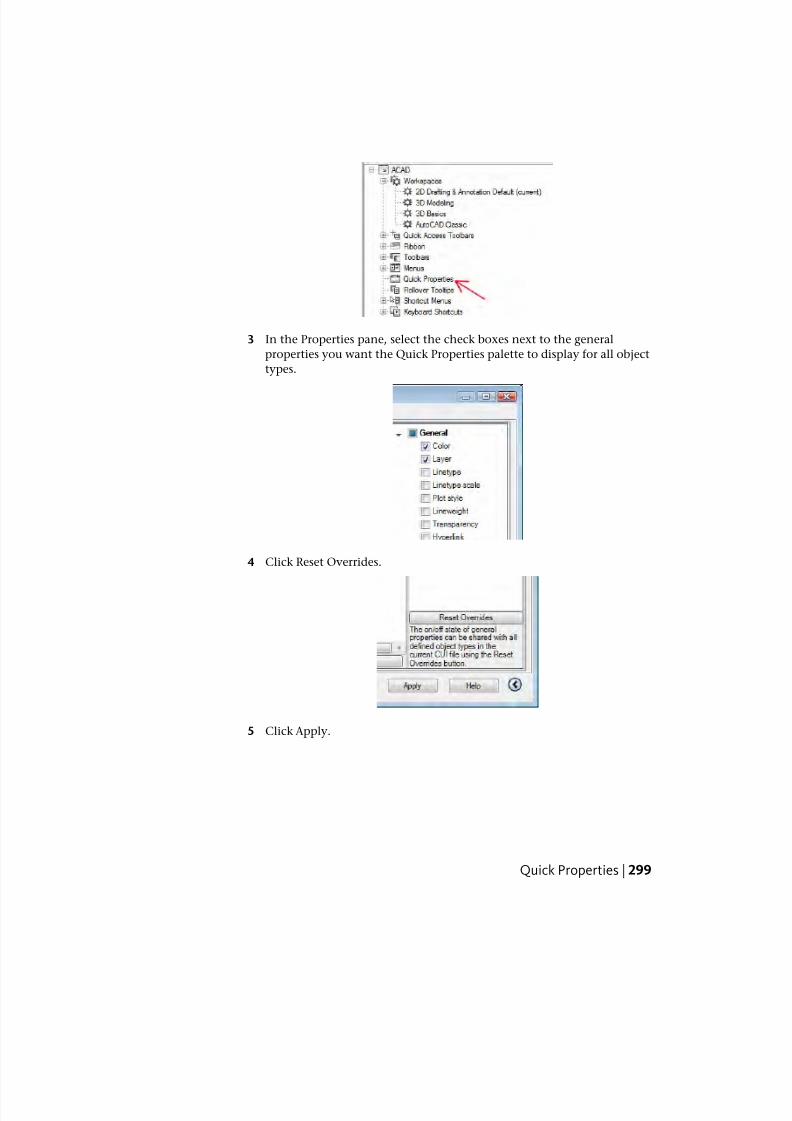
7/23/2019 Acad Customization
http://slidepdf.com/reader/full/acad-customization 307/553
3 In the Properties pane, select the check boxes next to the general
properties you want the Quick Properties palette to display for all object
types.
4 Click Reset Overrides.
5 Click Apply.
Quick Properties | 299
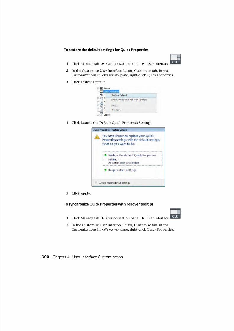
7/23/2019 Acad Customization
http://slidepdf.com/reader/full/acad-customization 308/553
To restore the default settings for Quick Properties
1 Click Manage tab ➤ Customization panel ➤ User Interface.
2 In the Customize User Interface Editor, Customize tab, in the
Customizations In <file name> pane, right-click Quick Properties.
3 Click Restore Default.
4 Click Restore the Default Quick Properties Settings.
5 Click Apply.
To synchronize Quick Properties with rollover tooltips
1 Click Manage tab ➤ Customization panel ➤ User Interface.
2 In the Customize User Interface Editor, Customize tab, in the
Customizations In <file name> pane, right-click Quick Properties.
300 | Chapter 4 User Interface Customization
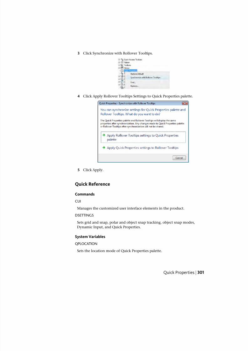
7/23/2019 Acad Customization
http://slidepdf.com/reader/full/acad-customization 309/553
3 Click Synchronize with Rollover Tooltips.
4 Click Apply Rollover Tooltips Settings to Quick Properties palette.
5 Click Apply.
Quick Reference
Commands
CUI
Manages the customized user interface elements in the product.
DSETTINGS
Sets grid and snap, polar and object snap tracking, object snap modes,
Dynamic Input, and Quick Properties.
System Variables
QPLOCATION
Sets the location mode of Quick Properties palette.
Quick Properties | 301
7/23/2019 Acad Customization
http://slidepdf.com/reader/full/acad-customization 310/553
QPMODE
Sets the on or off state of Quick Properties palette.
Rollover TooltipsRollover tooltips display the current values of selected properties.
The properties and values that are displayed in a rollover tooltip can be
customized by object type. When customizing the display of the properties
for a rollover tooltip, you can display properties common to all object types
or properties that are specific to an object type. The available properties are
the same as those on the Properties and Quick Properties palettes.
NOTE You can synchronize the properties used for rollover tooltips with those
displayed on the Quick Properties palette.
Display Objects Properties on Rollover Tooltips
When customizing rollover tooltips, you control which object types display
a tooltip when the cursor hovers over an object in the drawing window. You
use the Objects pane to add and remove the object types for which you want
to see a rollover tooltip. Once an object type is listed in the Objects pane, you
can then specify which properties in the Properties pane are displayed on the
rollover tooltip for the selected object type.
You can change the general properties for a selected object type or for all
object types. Selecting an object type from the Objects pane allows you to
control the display of the general and object specific properties for that selected
object type. You can click the General button at the bottom of the Objects
pane to override the general properties of all object types.
When the General button at the bottom of the Objects pane is clicked, a list
of the general properties that can be used to override the properties of all
object types is displayed along with the Reset Overrides button. Select the
general properties that you want to display for all object types and click Reset
Overrides. However, after applying a general property to all object types you
can deselect any general property for a specific object type by selecting the
object type and deselecting the property.
NOTE When an object is not in the Object Type list on the Objects pane, the
general properties that are checked for all object types are displayed on the rollover
tooltips.
302 | Chapter 4 User Interface Customization
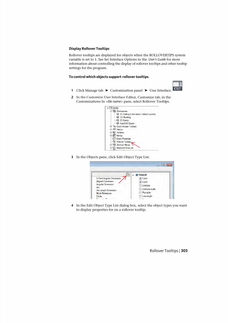
7/23/2019 Acad Customization
http://slidepdf.com/reader/full/acad-customization 311/553
Display Rollover Tooltips
Rollover tooltips are displayed for objects when the ROLLOVERTIPS systemvariable is set to 1. See Set Interface Options in the User ’ s Guide for more
information about controlling the display of rollover tooltips and other tooltip
settings for the program.
To control which objects support rollover tooltips
1 Click Manage tab ➤ Customization panel ➤ User Interface.
2 In the Customize User Interface Editor, Customize tab, in the
Customizations In <file name> pane, select Rollover Tooltips.
3 In the Objects pane, click Edit Object Type List.
4 In the Edit Object Type List dialog box, select the object types you want
to display properties for on a rollover tooltip.
Rollover Tooltips | 303
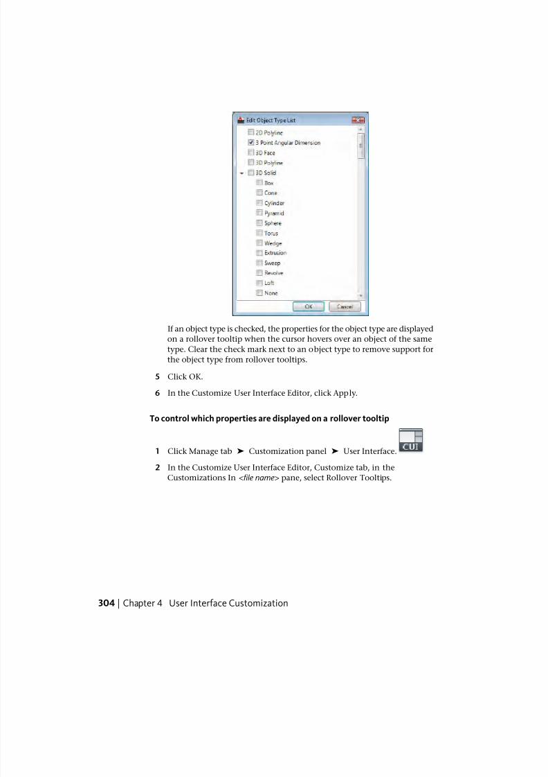
7/23/2019 Acad Customization
http://slidepdf.com/reader/full/acad-customization 312/553
If an object type is checked, the properties for the object type are displayed
on a rollover tooltip when the cursor hovers over an object of the same
type. Clear the check mark next to an object type to remove support for
the object type from rollover tooltips.
5 Click OK.
6 In the Customize User Interface Editor, click Apply.
To control which properties are displayed on a rollover tooltip
1 Click Manage tab ➤ Customization panel ➤ User Interface.
2 In the Customize User Interface Editor, Customize tab, in the
Customizations In <file name> pane, select Rollover Tooltips.
304 | Chapter 4 User Interface Customization
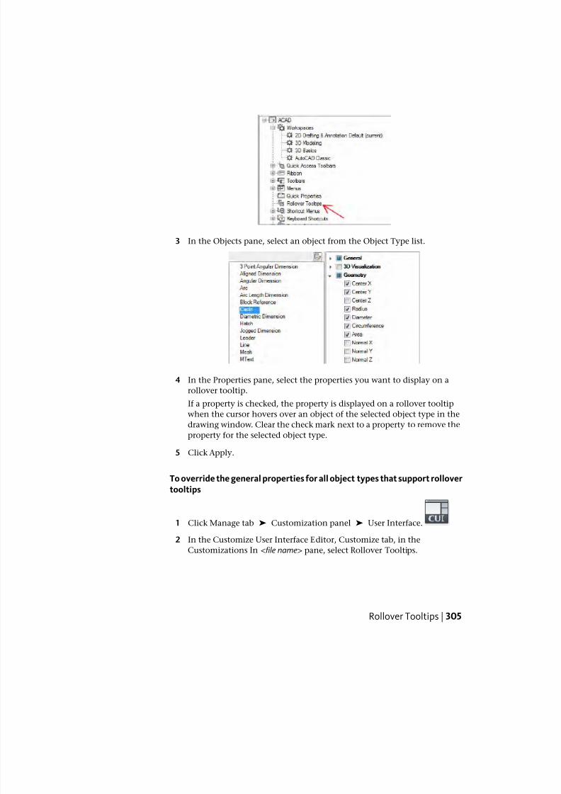
7/23/2019 Acad Customization
http://slidepdf.com/reader/full/acad-customization 313/553
3 In the Objects pane, select an object from the Object Type list.
4 In the Properties pane, select the properties you want to display on a
rollover tooltip.
If a property is checked, the property is displayed on a rollover tooltip
when the cursor hovers over an object of the selected object type in thedrawing window. Clear the check mark next to a property to remove the
property for the selected object type.
5 Click Apply.
To override the general properties for all object types that support rollovertooltips
1 Click Manage tab ➤ Customization panel ➤ User Interface.
2 In the Customize User Interface Editor, Customize tab, in the
Customizations In <file name> pane, select Rollover Tooltips.
Rollover Tooltips | 305
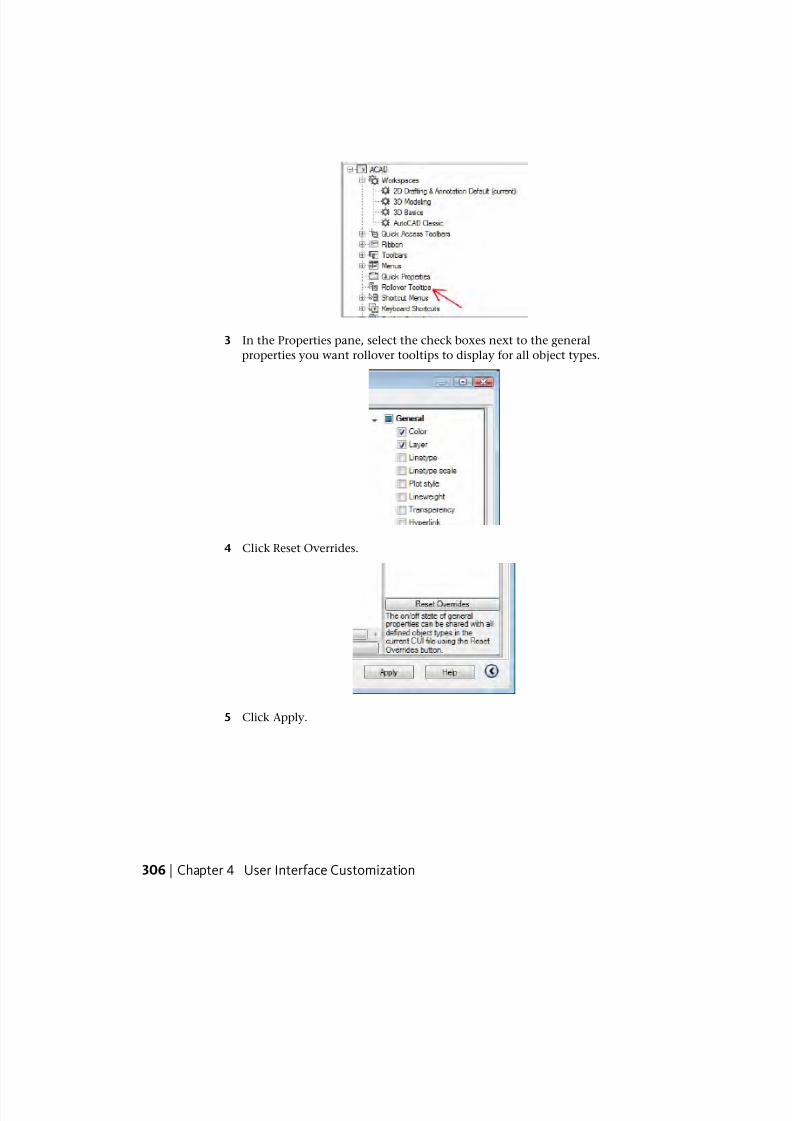
7/23/2019 Acad Customization
http://slidepdf.com/reader/full/acad-customization 314/553
3 In the Properties pane, select the check boxes next to the general
properties you want rollover tooltips to display for all object types.
4 Click Reset Overrides.
5 Click Apply.
306 | Chapter 4 User Interface Customization
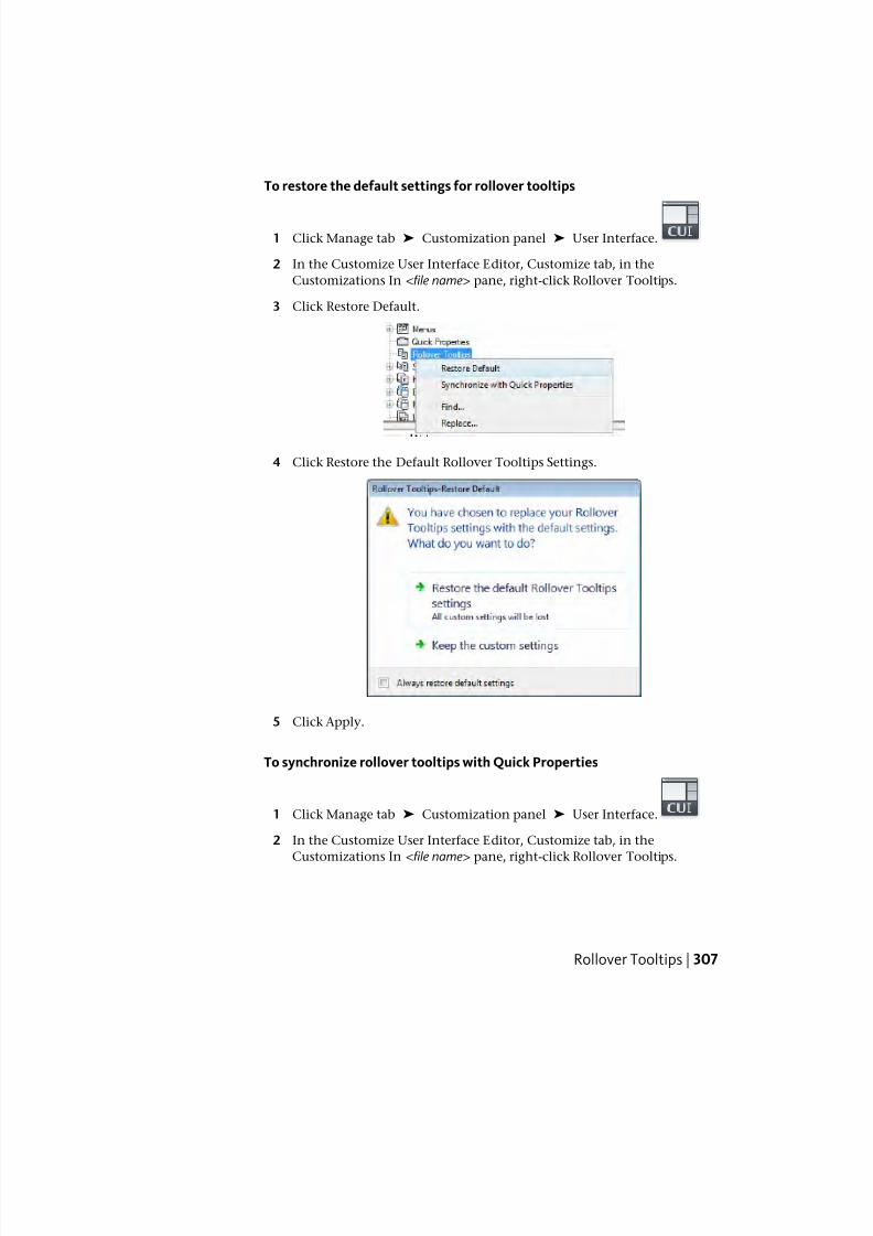
7/23/2019 Acad Customization
http://slidepdf.com/reader/full/acad-customization 315/553
To restore the default settings for rollover tooltips
1 Click Manage tab ➤ Customization panel ➤ User Interface.
2 In the Customize User Interface Editor, Customize tab, in the
Customizations In <file name> pane, right-click Rollover Tooltips.
3 Click Restore Default.
4 Click Restore the Default Rollover Tooltips Settings.
5 Click Apply.
To synchronize rollover tooltips with Quick Properties
1 Click Manage tab ➤ Customization panel ➤ User Interface.
2 In the Customize User Interface Editor, Customize tab, in the
Customizations In <file name> pane, right-click Rollover Tooltips.
Rollover Tooltips | 307
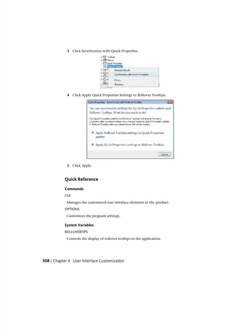
7/23/2019 Acad Customization
http://slidepdf.com/reader/full/acad-customization 316/553
3 Click Synchronize with Quick Properties.
4 Click Apply Quick Properties Settings to Rollover Tooltips.
5 Click Apply.
Quick Reference
Commands
CUI
Manages the customized user interface elements in the product.
OPTIONS
Customizes the program settings.
System Variables
ROLLOVERTIPS
Controls the display of rollover tooltips in the application.
308 | Chapter 4 User Interface Customization
7/23/2019 Acad Customization
http://slidepdf.com/reader/full/acad-customization 317/553
Keyboard ShortcutsShortcut keys can be used to start commands and to be temporary overridekeys to execute a command or change a setting when a key is pressed.
Shortcut KeysYou can assign shortcut keys (sometimes called accelerator keys) to commands
you use frequently.
Overview of Shortcut Keys
Shortcut keys are key combinations that start commands. For example, you
can press Ctrl+O to open a file and Ctrl+S to save a file, which is the same as
clicking Open and Save on the Quick Access toolbar or File menu.
To create a shortcut key, you start by dragging a command from the
Commands List pane to the Shortcut Keys node in the Customizations In <file
name > pane. Once you create a shortcut key, you assign a key combination
to it.
The following table shows the properties of the Save shortcut key as they
appear in the Properties pane.
Properties for the Save Shortcut Key
ExampleDescriptionPropertiespane item
SaveString that is only used in the CUI Editor and isnot displayed in the user interface.
Name
Saves the current
drawing
Text used to describe the element; does not
appear in the user interface.
Descrip-
tion
Displays the file name and ID for the extended
tooltip that is displayed when the cursor hovers
over a toolbar or panel button.
Extended
Help File
QSAVEString that contains the name of the command
that is related to the command.
Command
Display
Name
Keyboard Shortcuts | 309
7/23/2019 Acad Customization
http://slidepdf.com/reader/full/acad-customization 318/553
Properties for the Save Shortcut Key
ExampleDescriptionPropertiespane item
^C^C_qsaveThe command macro. It follows the standard
macro syntax.
Macro
CTRL+SSpecifies the keystroke combination that is used
to execute the macro. Click the [ ] button to
open the Shortcut Keys dialog box.
Key(s)
Keywords associated to a command. Tags
provide an additional field to search in the ap-
plication menu.
Tags
ID_SaveTag that uniquely identifies a command.Element ID
NOTE A shortcut key inherits its properties from the command that is used to
create it.
To create or modify a shortcut key
1 Click Manage tab ➤ Customization panel ➤ User Interface.
2 In the Customize User Interface Editor, Customize tab, click the plus sign
(+) next to Keyboard Shortcuts to expand it.
3 Click the plus sign (+) next to Shortcut Keys to expand it.
4 Do one of the following:
■ To create a shortcut key, in the Command List pane, drag the
command to the Shortcut Keys node of the Customizations In <file
name> pane.
310 | Chapter 4 User Interface Customization
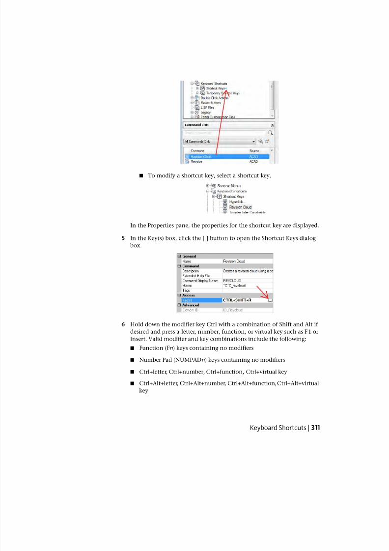
7/23/2019 Acad Customization
http://slidepdf.com/reader/full/acad-customization 319/553
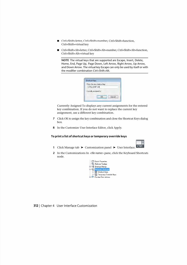
7/23/2019 Acad Customization
http://slidepdf.com/reader/full/acad-customization 320/553
■ Ctrl+Shift+letter, Ctrl+Shift+number, Ctrl+Shift+function,
Ctrl+Shift+virtual key
■ Ctrl+Shift+Alt+letter, Ctrl+Shift+Alt+number, Ctrl+Shift+Alt+function,
Ctrl+Shift+Alt+virtual key
NOTE The virtual keys that are supported are Escape, Insert, Delete,
Home, End, Page Up, Page Down, Left Arrow, Right Arrow, Up Arrow,
and Down Arrow. The virtual key Escape can only be used by itself or with
the modifier combination Ctrl+Shift+Alt.
Currently Assigned To displays any current assignments for the entered
key combination. If you do not want to replace the current key
assignment, use a different key combination.
7 Click OK to assign the key combination and close the Shortcut Keys dialog
box.
8 In the Customize User Interface Editor, click Apply.
To print a list of shortcut keys or temporary override keys
1 Click Manage tab ➤ Customization panel ➤ User Interface.
2 In the Customizations In <file name> pane, click the Keyboard Shortcuts
node.
312 | Chapter 4 User Interface Customization
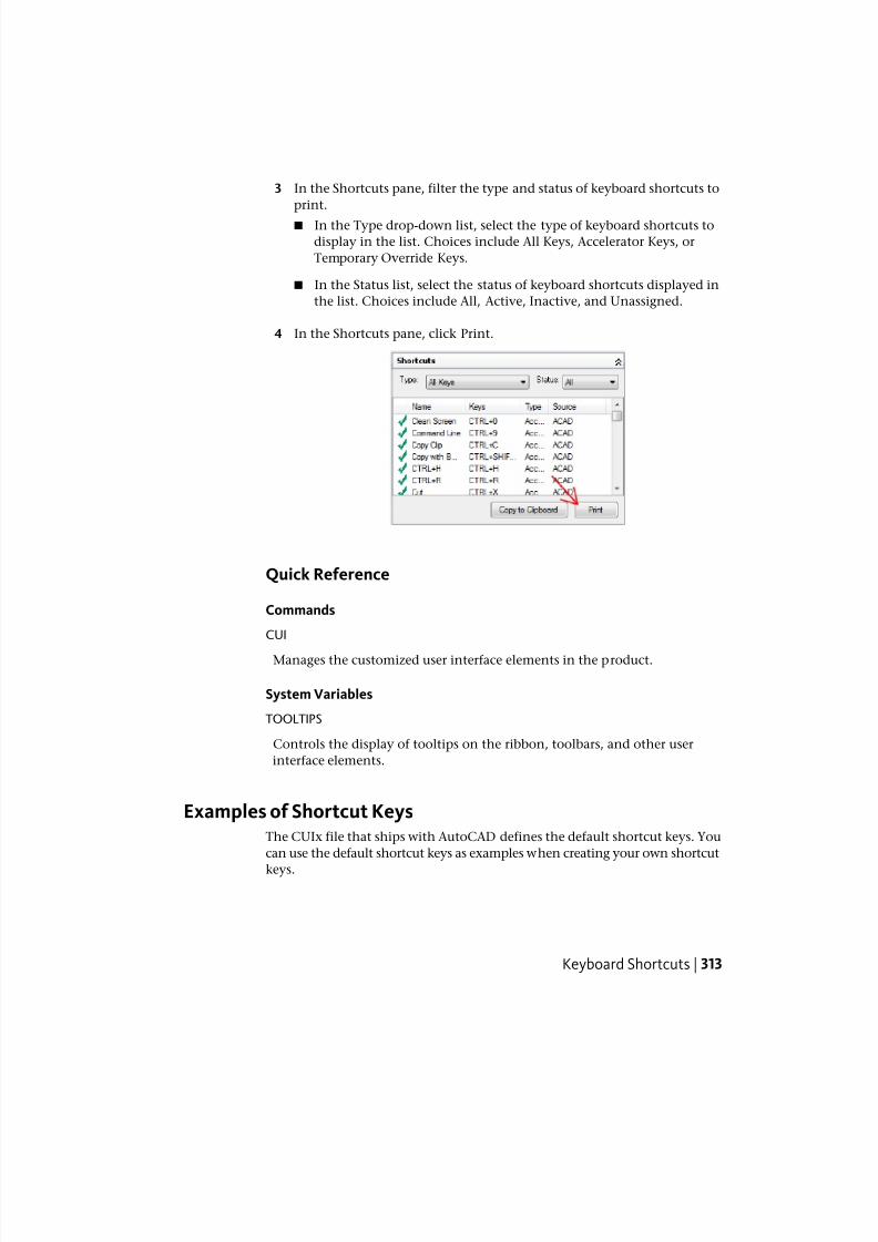
7/23/2019 Acad Customization
http://slidepdf.com/reader/full/acad-customization 321/553
3 In the Shortcuts pane, filter the type and status of keyboard shortcuts to
print.
■ In the Type drop-down list, select the type of keyboard shortcuts to
display in the list. Choices include All Keys, Accelerator Keys, or
Temporary Override Keys.
■ In the Status list, select the status of keyboard shortcuts displayed in
the list. Choices include All, Active, Inactive, and Unassigned.
4 In the Shortcuts pane, click Print.
Quick Reference
Commands
CUI
Manages the customized user interface elements in the product.
System Variables
TOOLTIPS
Controls the display of tooltips on the ribbon, toolbars, and other user
interface elements.
Examples of Shortcut KeysThe CUIx file that ships with AutoCAD defines the default shortcut keys. You
can use the default shortcut keys as examples when creating your own shortcut
keys.
Keyboard Shortcuts | 313
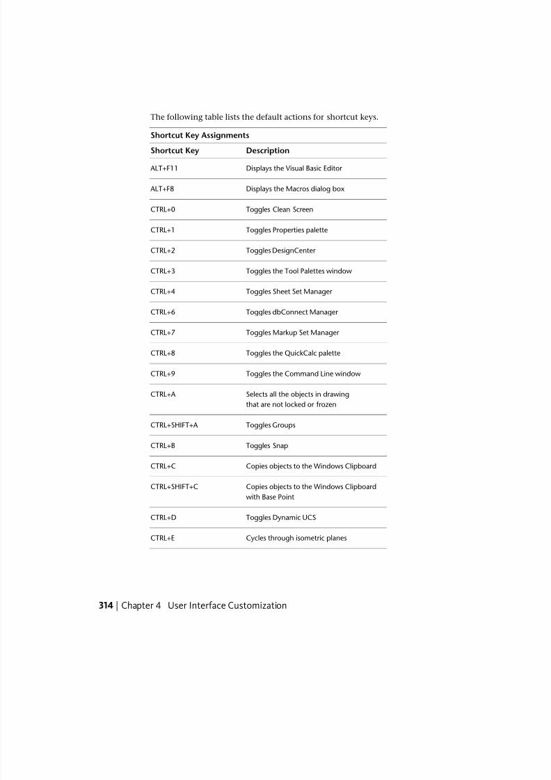
7/23/2019 Acad Customization
http://slidepdf.com/reader/full/acad-customization 322/553
The following table lists the default actions for shortcut keys.
Shortcut Key Assignments
DescriptionShortcut Key
Displays the Visual Basic Editor ALT+F11
Displays the Macros dialog box ALT+F8
Toggles Clean ScreenCTRL+0
Toggles Properties paletteCTRL+1
Toggles DesignCenter CTRL+2
Toggles the Tool Palettes windowCTRL+3
Toggles Sheet Set Manager CTRL+4
Toggles dbConnect Manager CTRL+6
Toggles Markup Set Manager CTRL+7
Toggles the QuickCalc paletteCTRL+8
Toggles the Command Line windowCTRL+9
Selects all the objects in drawingCTRL+A
that are not locked or frozen
Toggles GroupsCTRL+SHIFT+A
Toggles SnapCTRL+B
Copies objects to the Windows ClipboardCTRL+C
Copies objects to the Windows Clipboard
with Base Point
CTRL+SHIFT+C
Toggles Dynamic UCSCTRL+D
Cycles through isometric planesCTRL+E
314 | Chapter 4 User Interface Customization
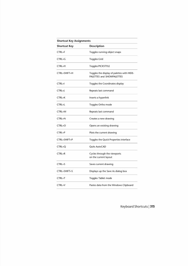
7/23/2019 Acad Customization
http://slidepdf.com/reader/full/acad-customization 323/553
Shortcut Key Assignments
DescriptionShortcut Key
Toggles running object snapsCTRL+F
Toggles GridCTRL+G
Toggles PICKSTYLECTRL+H
Toggles the display of palettes with HIDE-
PALETTES and SHOWPALETTES
CTRL+SHIFT+H
Toggles the Coordinates displayCTRL+I
Repeats last commandCTRL+J
Inserts a hyperlinkCTRL+K
Toggles Ortho modeCTRL+L
Repeats last commandCTRL+M
Creates a new drawingCTRL+N
Opens an existing drawingCTRL+O
Plots the current drawingCTRL+P
Toggles the Quick Properties interfaceCTRL+SHIFT+P
Quits AutoCADCTRL+Q
Cycles through the viewportsCTRL+R
on the current layout
Saves current drawingCTRL+S
Displays up the Save As dialog boxCTRL+SHIFT+S
Toggles Tablet modeCTRL+T
Pastes data from the Windows ClipboardCTRL+V
Keyboard Shortcuts | 315
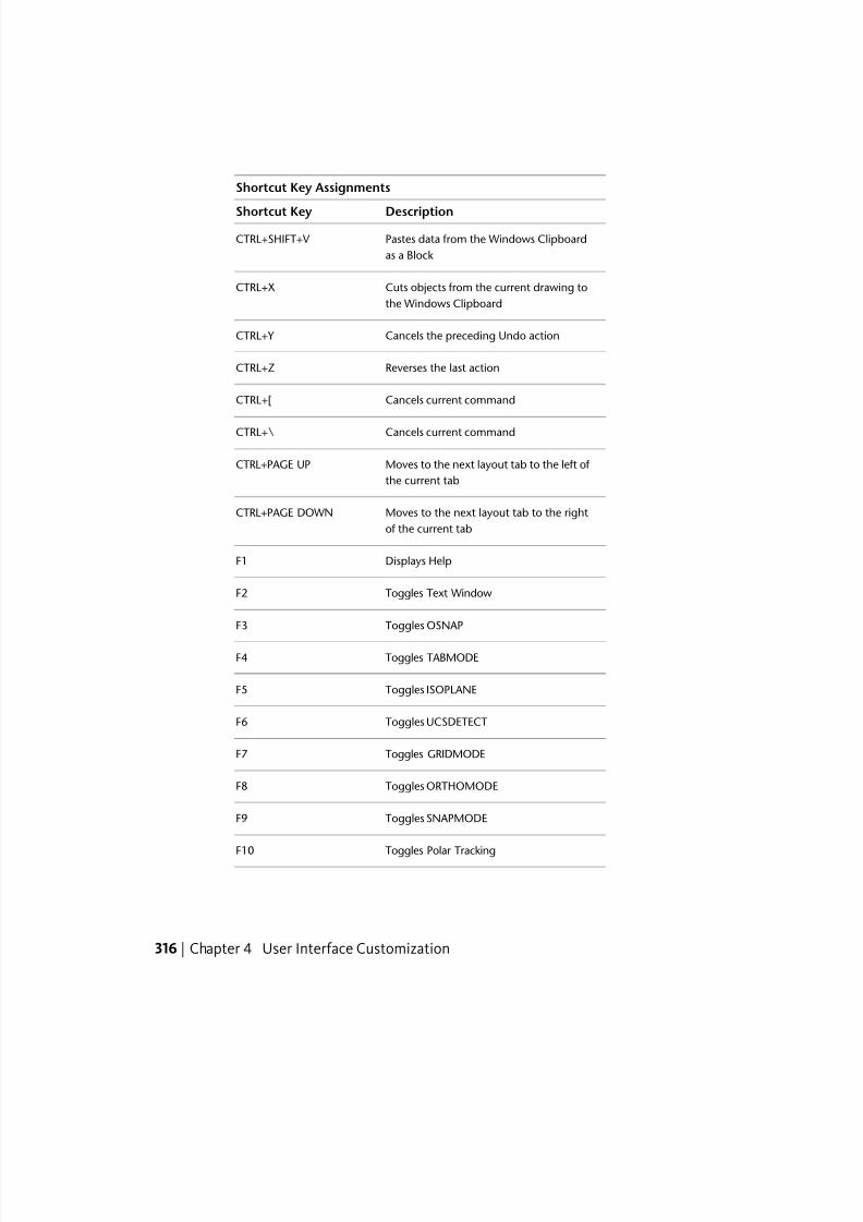
7/23/2019 Acad Customization
http://slidepdf.com/reader/full/acad-customization 324/553
Shortcut Key Assignments
DescriptionShortcut Key
Pastes data from the Windows Clipboard
as a Block
CTRL+SHIFT+V
Cuts objects from the current drawing to
the Windows Clipboard
CTRL+X
Cancels the preceding Undo actionCTRL+Y
Reverses the last actionCTRL+Z
Cancels current commandCTRL+[
Cancels current commandCTRL+\
Moves to the next layout tab to the left of
the current tab
CTRL+PAGE UP
Moves to the next layout tab to the right
of the current tab
CTRL+PAGE DOWN
Displays HelpF1
Toggles Text WindowF2
Toggles OSNAPF3
Toggles TABMODEF4
Toggles ISOPLANEF5
Toggles UCSDETECTF6
Toggles GRIDMODEF7
Toggles ORTHOMODEF8
Toggles SNAPMODEF9
Toggles Polar TrackingF10
316 | Chapter 4 User Interface Customization
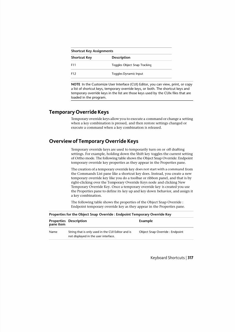
7/23/2019 Acad Customization
http://slidepdf.com/reader/full/acad-customization 325/553
Shortcut Key Assignments
DescriptionShortcut Key
Toggles Object Snap TrackingF11
Toggles Dynamic InputF12
NOTE In the Customize User Interface (CUI) Editor, you can view, print, or copy
a list of shortcut keys, temporary override keys, or both. The shortcut keys and
temporary override keys in the list are those keys used by the CUIx files that are
loaded in the program.
Temporary Override KeysTemporary override keys allow you to execute a command or change a setting
when a key combination is pressed, and then restore settings changed or
execute a command when a key combination is released.
Overview of Temporary Override Keys
Temporary override keys are used to temporarily turn on or off drafting
settings. For example, holding down the Shift key toggles the current setting
of Ortho mode. The following table shows the Object Snap Override: Endpoint
temporary override key properties as they appear in the Properties pane.
The creation of a temporary override key does not start with a command from
the Commands List pane like a shortcut key does. Instead, you create a newtemporary override key like you do a toolbar or ribbon panel, and that is by
right-clicking over the Temporary Override Keys node and clicking New
Temporary Override Key. Once a temporary override key is created you use
the Properties pane to define its key up and key down behavior, and assign it
a key combination.
The following table shows the properties of the Object Snap Override :
Endpoint temporary override key as they appear in the Properties pane.
Properties for the Object Snap Override : Endpoint Temporary Override Key
ExampleDescriptionPropertiespane item
Object Snap Override : EndpointString that is only used in the CUI Editor and isnot displayed in the user interface.
Name
Keyboard Shortcuts | 317
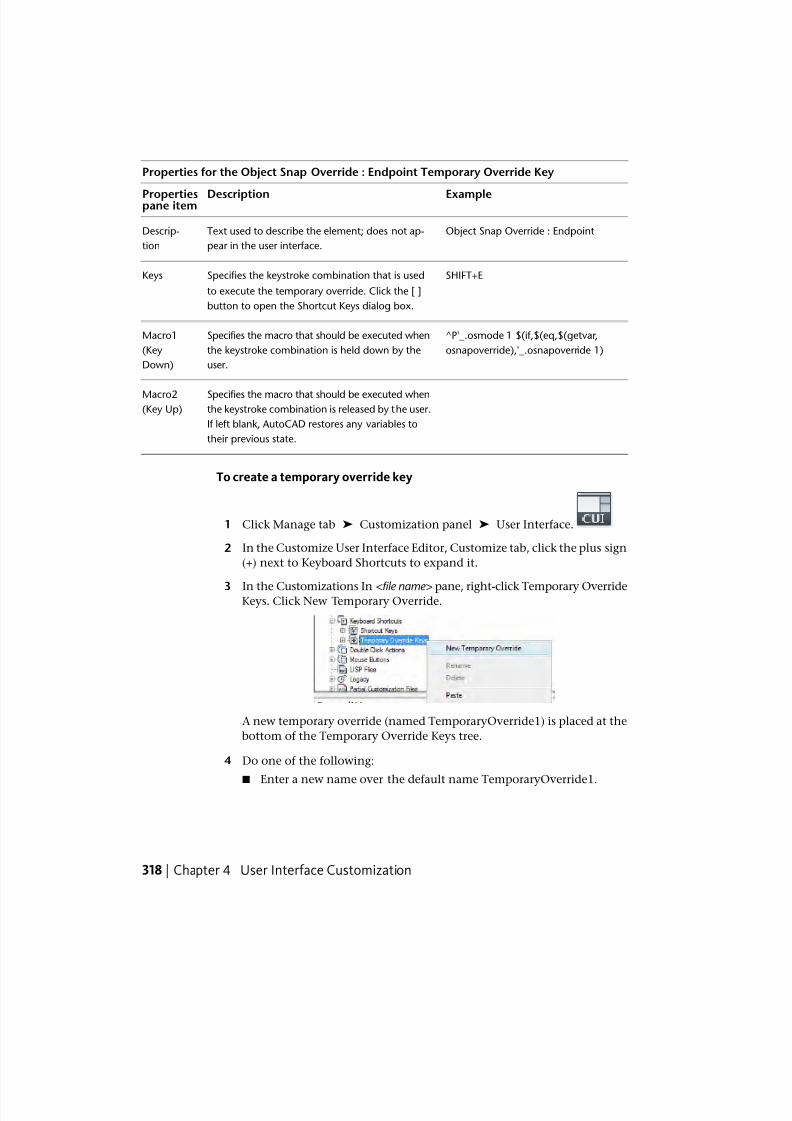
7/23/2019 Acad Customization
http://slidepdf.com/reader/full/acad-customization 326/553
Properties for the Object Snap Override : Endpoint Temporary Override Key
ExampleDescriptionPropertiespane item
Object Snap Override : EndpointText used to describe the element; does not ap-
pear in the user interface.
Descrip-
tion
SHIFT+ESpecifies the keystroke combination that is used
to execute the temporary override. Click the [ ]button to open the Shortcut Keys dialog box.
Keys
^P'_.osmode 1 $(if,$(eq,$(getvar,Specifies the macro that should be executed when
the keystroke combination is held down by the
user.
Macro1
(Key
Down)
osnapoverride),'_.osnapoverride 1)
Specifies the macro that should be executed whenthe keystroke combination is released by the user.
Macro2(Key Up)
If left blank, AutoCAD restores any variables to
their previous state.
To create a temporary override key
1 Click Manage tab ➤ Customization panel ➤ User Interface.
2 In the Customize User Interface Editor, Customize tab, click the plus sign
(+) next to Keyboard Shortcuts to expand it.
3 In the Customizations In <file name> pane, right-click Temporary OverrideKeys. Click New Temporary Override.
A new temporary override (named TemporaryOverride1) is placed at the
bottom of the Temporary Override Keys tree.
4 Do one of the following:
■
Enter a new name over the default name TemporaryOverride1.
318 | Chapter 4 User Interface Customization
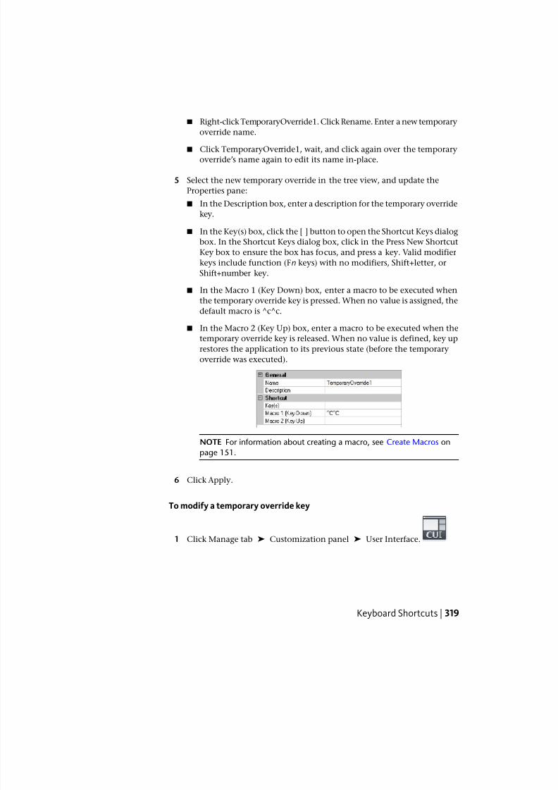
7/23/2019 Acad Customization
http://slidepdf.com/reader/full/acad-customization 327/553
■ Right-click TemporaryOverride1. Click Rename. Enter a new temporary
override name.
■ Click TemporaryOverride1, wait, and click again over the temporary
override’s name again to edit its name in-place.
5 Select the new temporary override in the tree view, and update the
Properties pane:
■ In the Description box, enter a description for the temporary override
key.
■ In the Key(s) box, click the [ ] button to open the Shortcut Keys dialog
box. In the Shortcut Keys dialog box, click in the Press New Shortcut
Key box to ensure the box has focus, and press a key. Valid modifier
keys include function (Fn keys) with no modifiers, Shift+letter, or
Shift+number key.■ In the Macro 1 (Key Down) box, enter a macro to be executed when
the temporary override key is pressed. When no value is assigned, the
default macro is ^c^c.
■ In the Macro 2 (Key Up) box, enter a macro to be executed when the
temporary override key is released. When no value is defined, key up
restores the application to its previous state (before the temporary
override was executed).
NOTE For information about creating a macro, see Create Macros on
page 151.
6 Click Apply.
To modify a temporary override key
1 Click Manage tab ➤ Customization panel ➤ User Interface.
Keyboard Shortcuts | 319
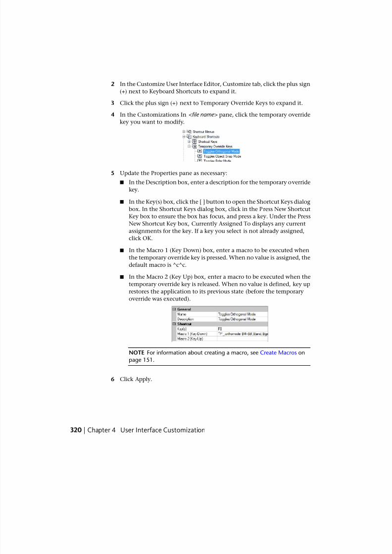
7/23/2019 Acad Customization
http://slidepdf.com/reader/full/acad-customization 328/553
2 In the Customize User Interface Editor, Customize tab, click the plus sign
(+) next to Keyboard Shortcuts to expand it.
3 Click the plus sign (+) next to Temporary Override Keys to expand it.
4 In the Customizations In <file name> pane, click the temporary override
key you want to modify.
5 Update the Properties pane as necessary:
■ In the Description box, enter a description for the temporary override
key.
■ In the Key(s) box, click the [ ] button to open the Shortcut Keys dialog
box. In the Shortcut Keys dialog box, click in the Press New Shortcut
Key box to ensure the box has focus, and press a key. Under the Press
New Shortcut Key box, Currently Assigned To displays any current
assignments for the key. If a key you select is not already assigned,
click OK.
■ In the Macro 1 (Key Down) box, enter a macro to be executed when
the temporary override key is pressed. When no value is assigned, the
default macro is ^c^c.
■ In the Macro 2 (Key Up) box, enter a macro to be executed when the
temporary override key is released. When no value is defined, key up
restores the application to its previous state (before the temporaryoverride was executed).
NOTE For information about creating a macro, see Create Macros on
page 151.
6 Click Apply.
320 | Chapter 4 User Interface Customization
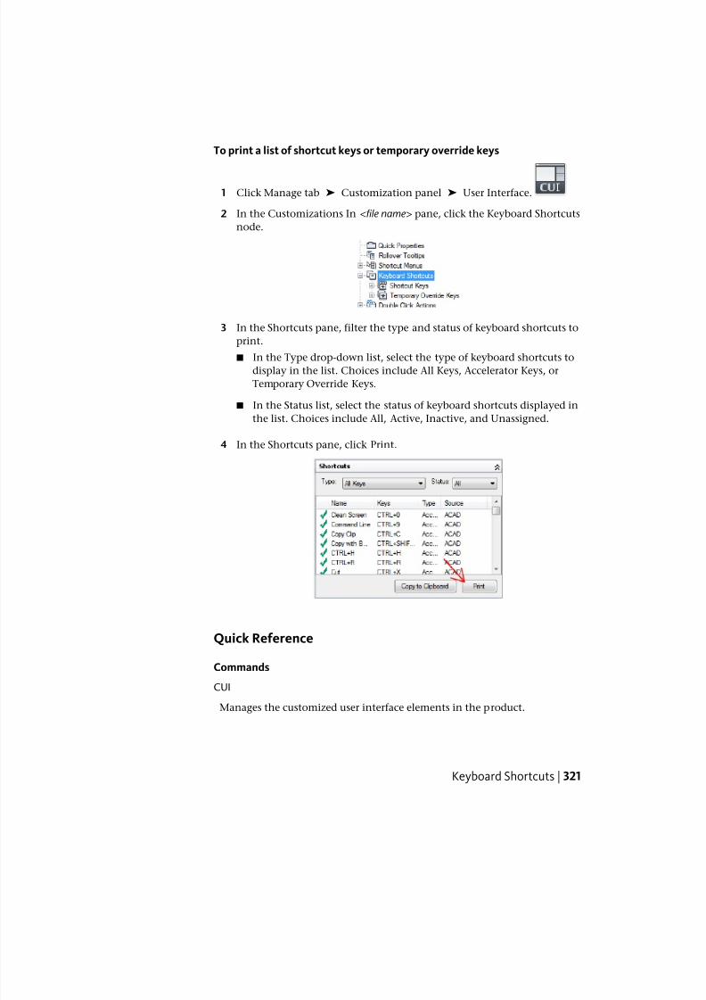
7/23/2019 Acad Customization
http://slidepdf.com/reader/full/acad-customization 329/553
To print a list of shortcut keys or temporary override keys
1 Click Manage tab ➤ Customization panel ➤ User Interface.
2 In the Customizations In <file name> pane, click the Keyboard Shortcuts
node.
3 In the Shortcuts pane, filter the type and status of keyboard shortcuts to
print.
■ In the Type drop-down list, select the type of keyboard shortcuts to
display in the list. Choices include All Keys, Accelerator Keys, or
Temporary Override Keys.
■ In the Status list, select the status of keyboard shortcuts displayed in
the list. Choices include All, Active, Inactive, and Unassigned.
4 In the Shortcuts pane, click Print.
Quick Reference
Commands
CUI
Manages the customized user interface elements in the product.
Keyboard Shortcuts | 321
7/23/2019 Acad Customization
http://slidepdf.com/reader/full/acad-customization 330/553
System Variables
TOOLTIPSControls the display of tooltips on the ribbon, toolbars, and other user
interface elements.
TEMPOVERRIDES
Turns temporary override keys on and off.
Examples of Temporary Override KeysThe CUIx file that ships with AutoCAD defines the default temporary override
keys. You can use the default temporary override keys as examples when
creating your own temporary override keys.
The following table lists the default actions for temporary override keys onan English U.S. keyboard. For more information about default temporary
override keys on other keyboards, see Override Object Snap Settings in the
User ’ s Guide .
Temporary Override Key Assignments
DescriptionTemporary Override Key
Toggles OSNAPF3
Toggles UCSDETECTF6
Toggles ORTHOMODEF8
Toggles SNAPMODEF9
Toggles Polar TrackingF10
Toggles Object Snap TrackingF11
Toggles Dynamic InputF12
Toggles ORTHOMODESHIFT
Toggles OSNAPSHIFT+’
Object Snap Override: Center SHIFT+,
322 | Chapter 4 User Interface Customization
7/23/2019 Acad Customization
http://slidepdf.com/reader/full/acad-customization 331/553
Temporary Override Key Assignments
DescriptionTemporary Override Key
Toggles Polar TrackingSHIFT+.
Toggles UCSDETECTSHIFT+/
Enables Object Snap EnforcementSHIFT+;
Toggles Object Snap TrackingSHIFT+]
Toggles OSNAPSHIFT+A
Object Snap Override: Center SHIFT+C
Disable All Snapping and TrackingSHIFT+D
Object Snap Override: EndpointSHIFT+E
Disable All Snapping and TrackingSHIFT+L
Object Snap Override: MidpointSHIFT+M
Object Snap Override: EndpointSHIFT+P
Toggles Object Snap TrackingSHIFT+Q
Enables Object Snap EnforcementSHIFT+S
Object Snap Override: MidpointSHIFT+V
Toggles Polar TrackingSHIFT+X
Toggles UCSDETECTSHIFT+Z
NOTE In the Customize User Interface (CUI) Editor, you can view, print, or copy
a list of shortcut keys, temporary override keys, or both. The shortcut keys and
temporary override keys in the list are those keys used by the CUIx files that are
loaded in the program.
Keyboard Shortcuts | 323
7/23/2019 Acad Customization
http://slidepdf.com/reader/full/acad-customization 332/553
Double Click ActionsYou can create a double click action which starts an editing command whenthe cursor is positioned over an object in a drawing and a double-click event
is registered from a pointing device.
Overview of Double Click ActionsDouble click actions execute a command that displays either the Properties
palette or a specialized editor that is more powerful, convenient, or frequently
used for the object type that is double-clicked in a drawing. The following
table shows the definition of the Attribute Block double click action in the
CUI Editor.
Properties for the Attribute Block double click action
ExampleDescriptionPropertiespane item
Attribute BlockString used to identify the double click action
in the CUI Editor.
Name
Text used to describe the element in the CUI
Editor.
Descrip-
tion
ATTBLOCKREFDetermines the type of object the double click
action is associated to. For information on the
Object
Name
object names that can be used, see Double Click
Action Object Names on page 327.
DC_0002Uniquely identifies a double click action in the
CUI Editor.
Element ID
To create a double click action
1 Click Manage tab ➤ Customization panel ➤ User Interface.
2 In the Customize User Interface Editor, Customize tab, in the
Customizations In <file name> pane, right-click Double Click Actions.
Click New Double Click Action.
324 | Chapter 4 User Interface Customization
7/23/2019 Acad Customization
http://slidepdf.com/reader/full/acad-customization 333/553
The new double click action (named DoubleClick1) is placed at the bottom
of the Double Click Actions tree.
3 Do one of the following:
■ Enter a new name over the default name DoubleClick1.
■ Right-click DoubleClick1. Click Rename. Enter a new double click
action name.
■ Click DoubleClick1, wait, and click again over the double click action’s
name again to edit its name in-place.
4 In the Properties pane, do the following:
■ In the Description box, enter a description for the double click action.
■ In the Object Name box, enter a DXF name or one of the special object
names used for an insert, surface, or underlay object. The value will
automatically be converted to uppercase after the box loses focus.
5 In the Command List pane, drag the command you want to add to thedouble click action in the Customizations In <file name> pane.
Double Click Actions | 325
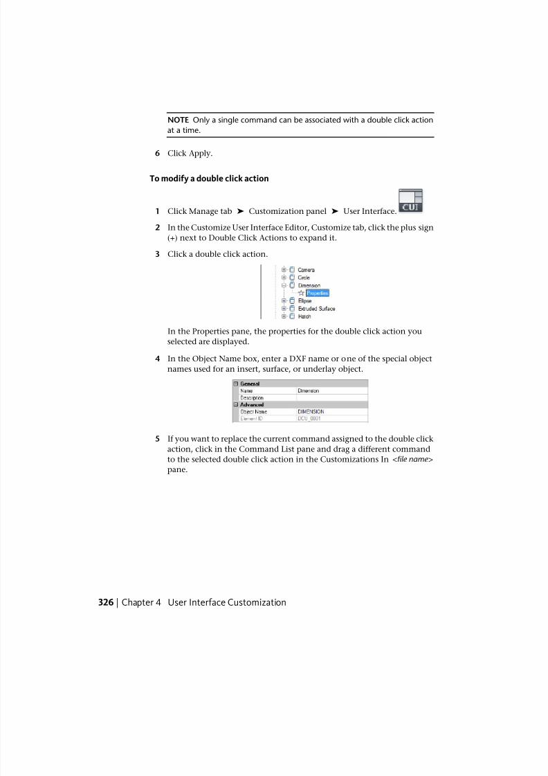
7/23/2019 Acad Customization
http://slidepdf.com/reader/full/acad-customization 334/553
NOTE Only a single command can be associated with a double click action
at a time.
6 Click Apply.
To modify a double click action
1 Click Manage tab ➤ Customization panel ➤ User Interface.
2 In the Customize User Interface Editor, Customize tab, click the plus sign
(+) next to Double Click Actions to expand it.
3 Click a double click action.
In the Properties pane, the properties for the double click action you
selected are displayed.
4 In the Object Name box, enter a DXF name or one of the special object
names used for an insert, surface, or underlay object.
5 If you want to replace the current command assigned to the double click
action, click in the Command List pane and drag a different command
to the selected double click action in the Customizations In <file name>
pane.
326 | Chapter 4 User Interface Customization
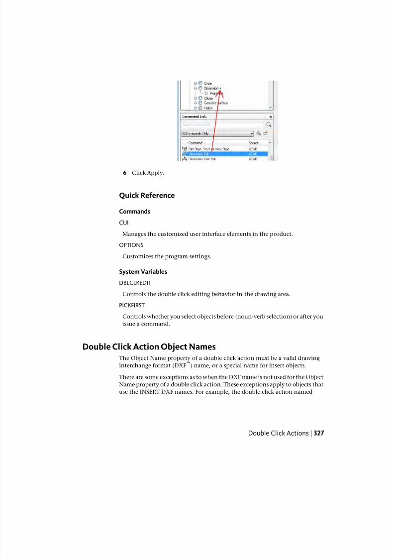
7/23/2019 Acad Customization
http://slidepdf.com/reader/full/acad-customization 335/553
6 Click Apply.
Quick Reference
Commands
CUI
Manages the customized user interface elements in the product.
OPTIONS
Customizes the program settings.
System Variables
DBLCLKEDIT
Controls the double click editing behavior in the drawing area.
PICKFIRST
Controls whether you select objects before (noun-verb selection) or after you
issue a command.
Double Click Action Object NamesThe Object Name property of a double click action must be a valid drawing
interchange format (DXF™
) name, or a special name for insert objects.
There are some exceptions as to when the DXF name is not used for the Object
Name property of a double click action. These exceptions apply to objects that
use the INSERT DXF names. For example, the double click action named
Double Click Actions | 327
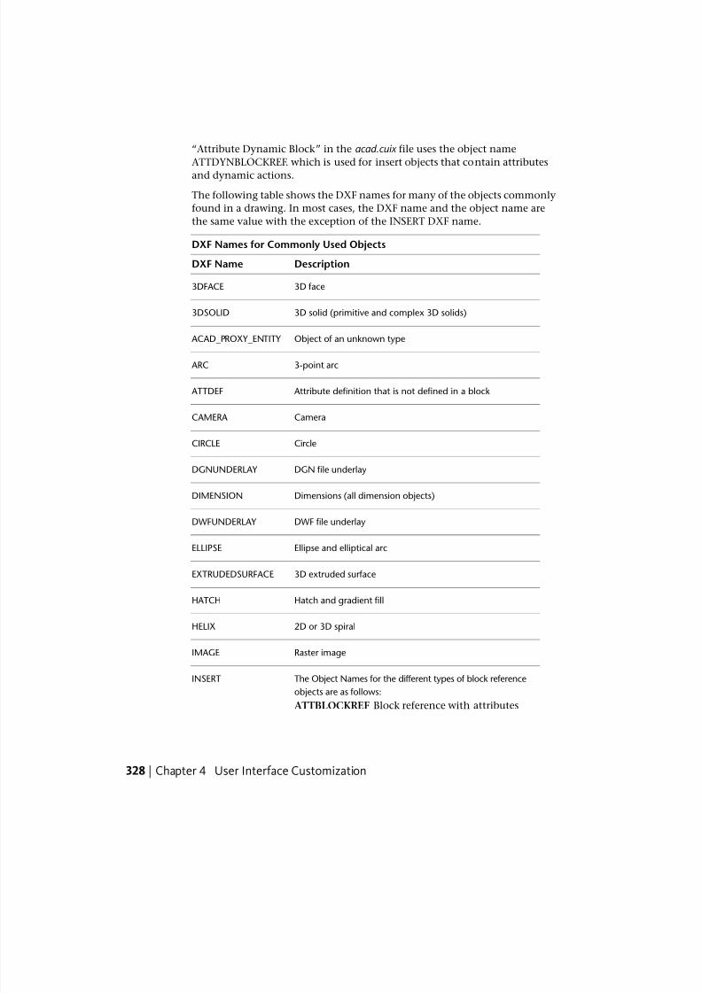
7/23/2019 Acad Customization
http://slidepdf.com/reader/full/acad-customization 336/553
“Attribute Dynamic Block” in the acad.cuix file uses the object name
ATTDYNBLOCKREF. which is used for insert objects that contain attributes
and dynamic actions.
The following table shows the DXF names for many of the objects commonly
found in a drawing. In most cases, the DXF name and the object name are
the same value with the exception of the INSERT DXF name.
DXF Names for Commonly Used Objects
DescriptionDXF Name
3D face3DFACE
3D solid (primitive and complex 3D solids)3DSOLID
Object of an unknown type ACAD_PROXY_ENTITY
3-point arc ARC
Attribute definition that is not defined in a block ATTDEF
CameraCAMERA
CircleCIRCLE
DGN file underlayDGNUNDERLAY
Dimensions (all dimension objects)DIMENSION
DWF file underlayDWFUNDERLAY
Ellipse and elliptical arcELLIPSE
3D extruded surfaceEXTRUDEDSURFACE
Hatch and gradient fillHATCH
2D or 3D spiralHELIX
Raster imageIMAGE
The Object Names for the different types of block reference
objects are as follows:
INSERT
ATTBLOCKREF Block reference with attributes
328 | Chapter 4 User Interface Customization
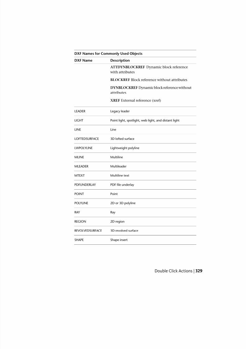
7/23/2019 Acad Customization
http://slidepdf.com/reader/full/acad-customization 337/553
DXF Names for Commonly Used Objects
DescriptionDXF NameATTDYNBLOCKREF Dynamic block reference
with attributes
BLOCKREF Block reference without attributes
DYNBLOCKREF Dynamic block reference without
attributes
XREF External reference (xref)
Legacy leader LEADER
Point light, spotlight, web light, and distant lightLIGHT
LineLINE
3D lofted surfaceLOFTEDSURFACE
Lightweight polylineLWPOLYLINE
MultilineMLINE
Multileader MLEADER
Multiline textMTEXT
PDF file underlayPDFUNDERLAY
PointPOINT
2D or 3D polylinePOLYLINE
RayRAY
2D regionREGION
3D revolved surfaceREVOLVEDSURFACE
Shape insertSHAPE
Double Click Actions | 329
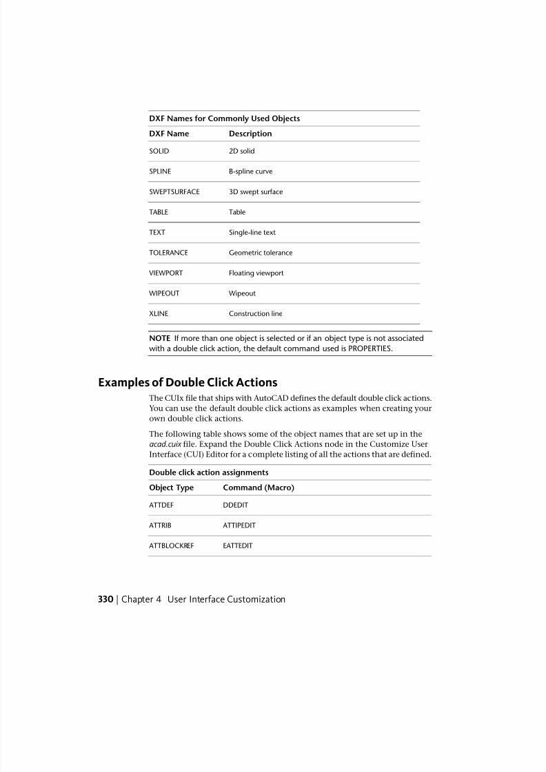
7/23/2019 Acad Customization
http://slidepdf.com/reader/full/acad-customization 338/553
DXF Names for Commonly Used Objects
DescriptionDXF Name
2D solidSOLID
B-spline curveSPLINE
3D swept surfaceSWEPTSURFACE
TableTABLE
Single-line textTEXT
Geometric toleranceTOLERANCE
Floating viewport VIEWPORT
Wipeout WIPEOUT
Construction lineXLINE
NOTE If more than one object is selected or if an object type is not associated
with a double click action, the default command used is PROPERTIES.
Examples of Double Click ActionsThe CUIx file that ships with AutoCAD defines the default double click actions.
You can use the default double click actions as examples when creating yourown double click actions.
The following table shows some of the object names that are set up in the
acad.cuix file. Expand the Double Click Actions node in the Customize User
Interface (CUI) Editor for a complete listing of all the actions that are defined.
Double click action assignments
Command (Macro)Object Type
DDEDIT ATTDEF
ATTIPEDIT ATTRIB
EATTEDIT ATTBLOCKREF
330 | Chapter 4 User Interface Customization
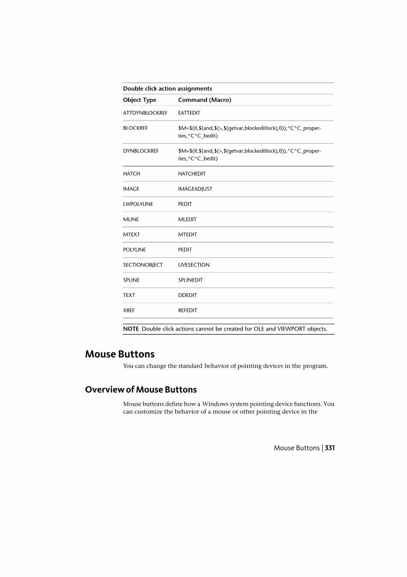
7/23/2019 Acad Customization
http://slidepdf.com/reader/full/acad-customization 339/553
Double click action assignments
Command (Macro)Object Type
EATTEDIT ATTDYNBLOCKREF
$M=$(if,$(and,$(>,$(getvar,blockeditlock),0)),^C^C_proper-
ties,^C^C_bedit)
BLOCKREF
$M=$(if,$(and,$(>,$(getvar,blockeditlock),0)),^C^C_proper-
ties,^C^C_bedit)
DYNBLOCKREF
HATCHEDITHATCH
IMAGEADJUSTIMAGE
PEDITLWPOLYLINE
MLEDITMLINE
MTEDITMTEXT
PEDITPOLYLINE
LIVESECTIONSECTIONOBJECT
SPLINEDITSPLINE
DDEDITTEXT
REFEDITXREF
NOTE Double click actions cannot be created for OLE and VIEWPORT objects.
Mouse ButtonsYou can change the standard behavior of pointing devices in the program.
Overview of Mouse Buttons
Mouse buttons define how a Windows system pointing device functions. Youcan customize the behavior of a mouse or other pointing device in the
Mouse Buttons | 331
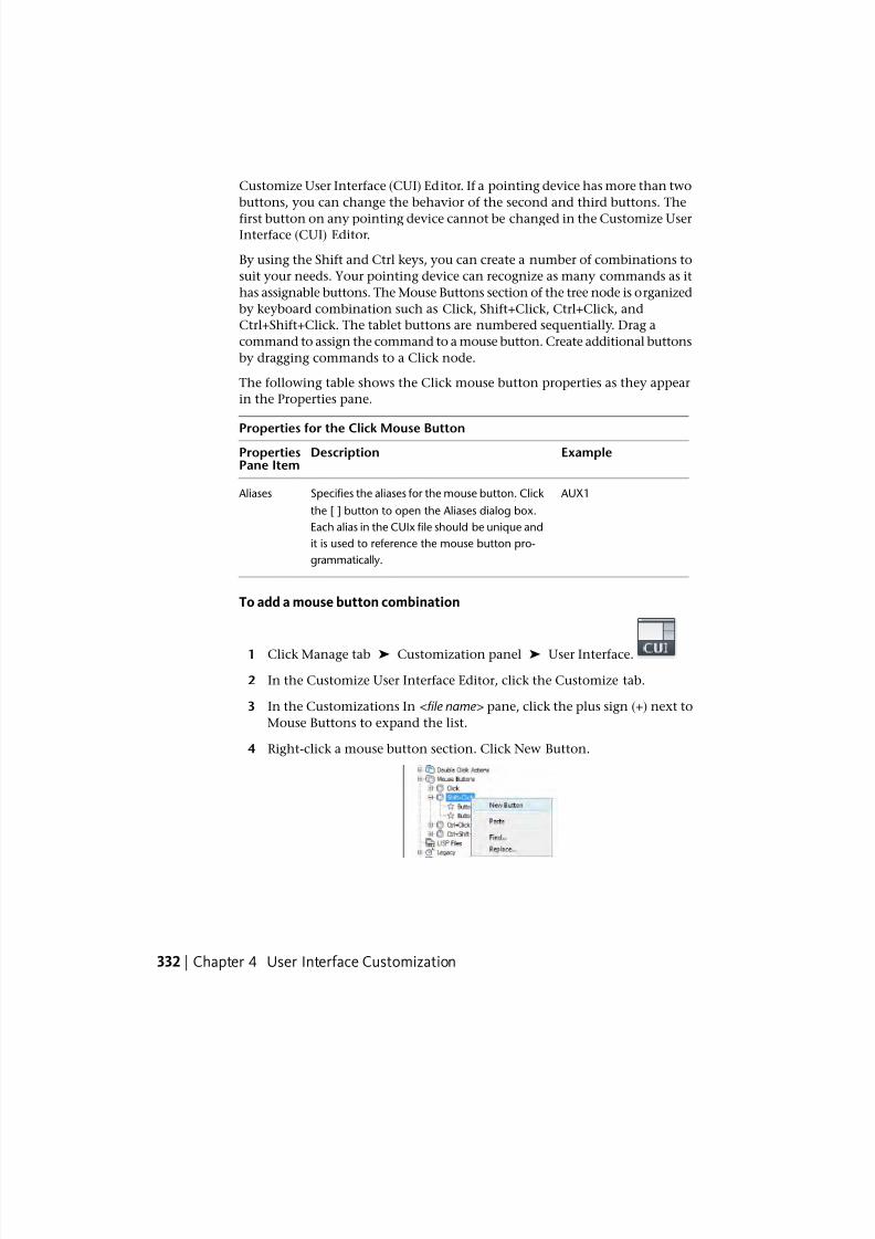
7/23/2019 Acad Customization
http://slidepdf.com/reader/full/acad-customization 340/553
Customize User Interface (CUI) Editor. If a pointing device has more than two
buttons, you can change the behavior of the second and third buttons. The
first button on any pointing device cannot be changed in the Customize UserInterface (CUI) Editor.
By using the Shift and Ctrl keys, you can create a number of combinations to
suit your needs. Your pointing device can recognize as many commands as it
has assignable buttons. The Mouse Buttons section of the tree node is organized
by keyboard combination such as Click, Shift+Click, Ctrl+Click, and
Ctrl+Shift+Click. The tablet buttons are numbered sequentially. Drag a
command to assign the command to a mouse button. Create additional buttons
by dragging commands to a Click node.
The following table shows the Click mouse button properties as they appear
in the Properties pane.
Properties for the Click Mouse ButtonExampleDescriptionProperties
Pane Item
AUX1Specifies the aliases for the mouse button. Click
the [ ] button to open the Aliases dialog box.
Aliases
Each alias in the CUIx file should be unique and
it is used to reference the mouse button pro-
grammatically.
To add a mouse button combination
1 Click Manage tab ➤ Customization panel ➤ User Interface.
2 In the Customize User Interface Editor, click the Customize tab.
3 In the Customizations In <file name> pane, click the plus sign (+) next to
Mouse Buttons to expand the list.
4 Right-click a mouse button section. Click New Button.
332 | Chapter 4 User Interface Customization
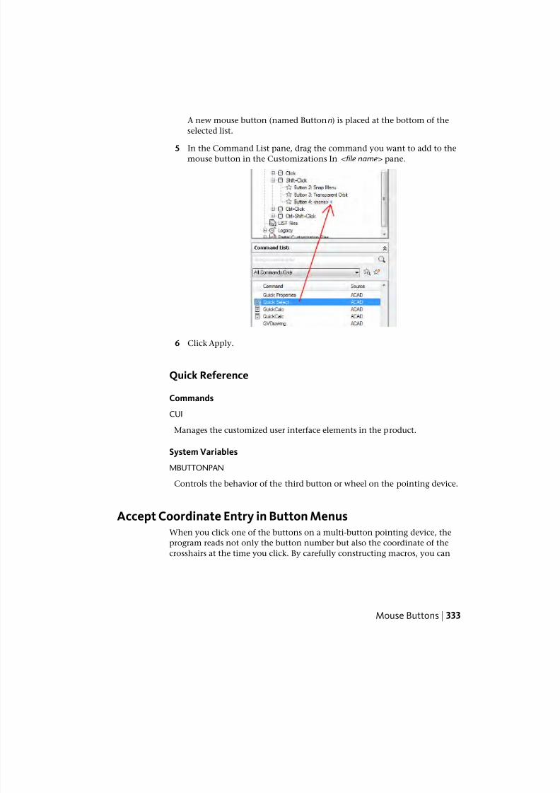
7/23/2019 Acad Customization
http://slidepdf.com/reader/full/acad-customization 341/553
A new mouse button (named Buttonn) is placed at the bottom of the
selected list.
5 In the Command List pane, drag the command you want to add to the
mouse button in the Customizations In <file name> pane.
6 Click Apply.
Quick Reference
Commands
CUIManages the customized user interface elements in the product.
System Variables
MBUTTONPAN
Controls the behavior of the third button or wheel on the pointing device.
Accept Coordinate Entry in Button MenusWhen you click one of the buttons on a multi-button pointing device, the
program reads not only the button number but also the coordinate of the
crosshairs at the time you click. By carefully constructing macros, you can
Mouse Buttons | 333
7/23/2019 Acad Customization
http://slidepdf.com/reader/full/acad-customization 342/553
choose to either ignore the coordinate or use it with the command activated
by the button.
As described in Pause for User Input in Macros on page 156, you can include
a backslash (\) in a command to pause for user input. For the Mouse and
Digitize Buttons menus, the coordinate of the crosshairs is supplied as user
input when the button is clicked. This occurs only for the first backslash in
the command; if the item contains no backslashes, the crosshairs coordinate
is not used. Consider the following commands:
line
line \
The first button starts the LINE command and displays the Specify First Point
prompt in the normal fashion. The second button also starts the LINE
command, but the program uses the current crosshairs location at the Specify
First Point prompt and displays the Specify Next Point prompt.
Quick Reference
Commands
CUI
Manages the customized user interface elements in the product.
Legacy Interface ElementsThe term “legacy” refers to those user interface elements that are not
commonly used with the current version of the program, but are still supportedbecause some users prefer them to alternative user interface elements that are
now provided.
Create Tablet MenusYou can configure up to four areas of your digitizing tablet as menu areas for
command input.
The nodes in the Customize User Interface (CUI) Editor are labeled Tablet
Menu 1 through Tablet Menu 4 and define the macros associated with tablet
selections.
The tablet menu areas that you define with the Cfg option of the TABLET
command are divided into equal-sized menu selection boxes, which are
334 | Chapter 4 User Interface Customization
7/23/2019 Acad Customization
http://slidepdf.com/reader/full/acad-customization 343/553
determined by the number of columns and rows you specify in each area.
These tablet menu selection boxes correspond directly with the lines that
follow the Tablet section labels from left to right and top to bottom (whetheror not they contain text).
For example, if you configure a menu area for five columns and four rows,
the command on the line immediately following the Row label corresponds
to the left-most selection box in the top row. The program can recognize up
to 32,766 commands in each tablet section, which should be more than
enough for any tablet menu.
You can add your own macros to the Macros cell in the Properties pane. The
command labels in this area correspond to the 225 boxes at the top of your
tablet template (rows A through I and columns 1 through 25). You can add a
macro using standard command syntax. The following table shows the Click
mouse button properties as they appear in the Properties pane.
Properties for the Tablet Menu 1
ExampleDescriptionPropertiespane item
TABLET1, TABLET1STDSpecifies the aliases for the tablet menu. Click
the [ ] button to open the Aliases dialog box.
Aliases
Each alias in the CUIx file should be unique and
it is used to reference the tablet menu program-
matically.
9Number of rows that can be customized for the
tablet menu.
Rows
25Number of columns that can be customized for
the tablet menu.
Columns
To define rows and columns in a tablet menu
1 Click Manage tab ➤ Customization panel ➤ User Interface.
2 In the Customize User Interface Editor, Customize tab, in the
Customizations In <file name> pane, click the plus sign (+) next to Legacy
to expand it.
3 Click the plus sign (+) next to Tablet Menus to expand it.
4 Click the plus sign (+) next to a tablet menu to expand it.
Legacy Interface Elements | 335
7/23/2019 Acad Customization
http://slidepdf.com/reader/full/acad-customization 344/553
5 Click the row that you want to define.
6 In the Command List pane, locate the command you want to add.
7 Drag the command to a column.
8 Click Apply.
To clear a tablet menu assignment
1 Click Manage tab ➤ Customization panel ➤ User Interface.
2 In the Customize User Interface Editor, Customize tab, in the
Customizations In <file name> pane, click the plus sign (+) next to Legacy
to expand it.
3 Click the plus sign (+) next to Tablet Menus to expand it.
4 Click the plus sign (+) next to a tablet menu to expand it.
5 Right-click the row or column that you want to clear. Click Clear
Assignment.
6 Click Apply.
Quick Reference
Commands
CUI
Manages the customized user interface elements in the product.
TABLET
Calibrates, configures, and turns on and off an attached digitizing tablet.
Customize Tablet ButtonsTo customize tablet buttons, you follow the same procedures as for customizing
mouse buttons.
Tablet buttons are the buttons that are found on the pointing device, also
known as a puck, used with a digitizer tablet. Pucks come in a variety of shapes,
336 | Chapter 4 User Interface Customization
7/23/2019 Acad Customization
http://slidepdf.com/reader/full/acad-customization 345/553
sizes, and button configurations. You can customize all the buttons on a puck
except for the first button.
Some hardware manufacturers utilize a slightly different button layout from
one puck to another. One might start with the first button in the upper-left
corner and count across and down from 1 through F, while another might
start in the upper-left corner and have a different numbering scheme.
NOTE It is important to test your button assignments as they are assigned to
ensure the proper button is being mapped. You may need to refer to your owners
manual that came with your puck for how the buttons are laid out.
To customize tablet buttons, you follow the same procedures as for customizing
mouse buttons.
For more information about customizing tablet buttons, see Mouse Buttons
on page 331.
Quick Reference
Commands
CUI
Manages the customized user interface elements in the product.
Create Screen MenusScreen menus provide a legacy interface for displaying menus in a palette.
You create and edit screen menus in the Customize User Interface (CUI) Editor.
By default, the screen menu is disabled. You turn on the screen menu display
in the Options dialog box, Display tab. In addition, the MENUCTL system
variable controls whether the screen menu is updated as you enter commands
at the command prompt.
In the Customize User Interface (CUI) Editor, each screen menu consists of
several menu lines, which define the screen submenus. You assign a submenu
to a screen menu by dragging it to the screen menu in the Customize In pane.
You assign a command to a menu by dragging it from the Command List
pane to the numbered line in the menu. Unassigned lines are left empty in
the menu.
Legacy Interface Elements | 337
7/23/2019 Acad Customization
http://slidepdf.com/reader/full/acad-customization 346/553
Edit Screen Menu Properties
You can modify screen menu properties, as shown in the following table.
Properties for screen menus
ExampleDescriptionPropertiespane item
SCREENSets the name of the menu.Name
Text that describes the element; does
not appear in the user interface.
Description
1Sets the start line of the screen menu
submenu.
Start line
26Sets the number of lines in a screensubmenu.
Number of lines
SCREEN, SSpecifies the alias for the screen
menu. “Collection” is displayed if
Aliases
multiple definitions are assigned to
this alias. Click the [ ] button to open
the Aliases dialog box.
For the AutoCAD screen menu, which is the root menu, the aliases in the
Aliases box are Screen (which represents the beginning of the screen menu)
and S (which represents the submenu section label). Line assignments for
other menus define the order of the options on the menu. For example, the
File menu on Line 3 in the tree view of the AutoCAD screen menu is in thethird position on the AutoCAD screen menu.
The submenu names in the tree view correspond to the name of the first
submenu item. For example, the New submenu contains commands such as
OPEN, QSAVE, and SAVEAS—in addition to NEW. The Aliases box for these
submenus defines which menu contains them and the Start Line box specifies
their position on that menu. The New submenu is displayed in position 3 on
the File screen menu. Therefore, in the Properties pane, its start line is 3. When
you double-click Aliases to display the Aliases dialog box, you can see that its
menu assignment is 01_FILE.
You can designate which menu items are always displayed by controlling the
start line settings. For example, since the New submenu is set to start on line
3, the menu items on lines 1 and 2 of the AutoCAD screen menu (the AutoCAD
338 | Chapter 4 User Interface Customization

7/23/2019 Acad Customization
http://slidepdf.com/reader/full/acad-customization 347/553
and **** menu options) continue to display when the New submenu is
displayed.
Similarly, you can set a menu to mask or show menu options on other menus
by using blank lines. For example, there are only 22 lines (including blank
lines) defined for the New submenu. Therefore, the Assist and Last submenus
on lines 25 and 26 of the AutoCAD screen menu continue to be displayed
when the New submenu is selected. An option on line 22, however, would be
hidden.
To display the screen menu
1 Click Application menu ➤ Options.
2 In the Options dialog box, Display tab, under Window Elements, select
Display Screen Menu.
3 Click OK.
To set screen menus to reflect the current command
1 At the Command prompt, enter menuctl.
2 Do one of the following:
■ Enter 1 to set screen menus to reflect the current command.
■ Enter 0 to set screen menus to ignore the current command.
To add commands to the screen menu
1 Click Manage tab ➤ Customization panel ➤ User Interface.
2 In the Customize User Interface Editor, Customize tab, in the
Customizations In <file name> pane, click the plus sign (+) next to Legacy
to expand the list.
3 In the Legacy list, click the plus sign (+) next to a screen menu to expand
the list.
4 In the Command List pane, locate the command you want to add. Drag
the command to the screen menu. An arrow is displayed next to the
cursor when the command can be dropped.
5 Click Apply.
Legacy Interface Elements | 339
7/23/2019 Acad Customization
http://slidepdf.com/reader/full/acad-customization 348/553
To create a submenu on a screen menu
1 Click Manage tab ➤ Customization panel ➤ User Interface.
2 In the Customize User Interface Editor, Customize tab, in the
Customizations In <file name> pane, click the plus sign (+) next to Legacy
to expand the list.
3 In the Legacy list, right-click Screen Menu. Click New Screen Menu.
A new screen menu (named ScreenMenu1) is placed at the bottom of the
Screen Menus tree.
4 Do one of the following:
■ Enter a new name over the default name ScreenMenu1.
■ Right-click ScreenMenu1. Click Rename. Then, enter a new menuname.
■ Click ScreenMenu1, wait, and click again over the screen menu’s name
again to edit its name in-place.
5 Select the new screen menu in the tree view, and update the Properties
pane as follows:
■ In the Description box, enter a description for the screen menu.
■ In the Start Line box, enter the line number for the first option in the
menu.
■ In the Number of Lines box, enter the number of total lines that
should be available for the screen menu.
■ In the Aliases box, enter an alias.
6 In the Command List pane, drag the command to a location just below
the screen menu in the Customizations In <file name> pane.
7 Click Apply.
340 | Chapter 4 User Interface Customization
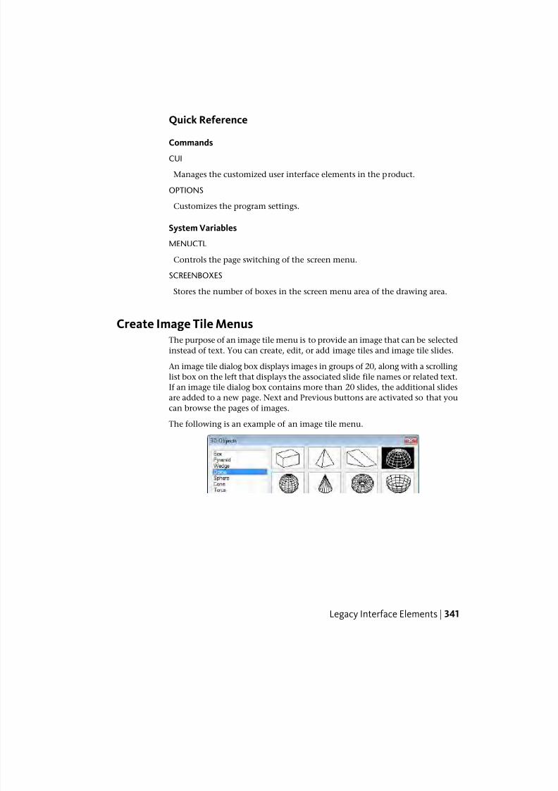
7/23/2019 Acad Customization
http://slidepdf.com/reader/full/acad-customization 349/553
Quick Reference
Commands
CUI
Manages the customized user interface elements in the product.
OPTIONS
Customizes the program settings.
System Variables
MENUCTL
Controls the page switching of the screen menu.
SCREENBOXES
Stores the number of boxes in the screen menu area of the drawing area.
Create Image Tile MenusThe purpose of an image tile menu is to provide an image that can be selected
instead of text. You can create, edit, or add image tiles and image tile slides.
An image tile dialog box displays images in groups of 20, along with a scrolling
list box on the left that displays the associated slide file names or related text.
If an image tile dialog box contains more than 20 slides, the additional slides
are added to a new page. Next and Previous buttons are activated so that you
can browse the pages of images.
The following is an example of an image tile menu.
Legacy Interface Elements | 341
7/23/2019 Acad Customization
http://slidepdf.com/reader/full/acad-customization 350/553
You define an image tile menu in the Customize User Interface (CUI) Editor.
The following table shows the properties for an image tile menu.
Properties for the Tiled Viewport Layout image tile menu
ExampleDescriptionPropertiespane item
Tiled Viewport LayoutString that is used only in the CUI Editor and is
not displayed in the user interface.
Name
Text that describes the element and does not
appear in the user interface.
Descrip-
tion
image_vportiSpecifies the aliases for the image tile menu.
Click the [ ] button to open the Aliases dialog
Aliases
box. Each alias in the CUIx file should be uniqueand it is used to reference the image tile menu
programmatically.
The following table shows the properties for an image tile slide.
Properties of the Four: Equal tile slide on the Tiled Viewport Layout imagetile menu
ExampleDescriptionPropertiespane item
Four: EqualString displayed in the list box on the left side
of the image tile menu dialog box. The string
Name
must include alphanumeric characters with no
punctuation other than a hyphen (-) or an un-derscore (_).
Tiled Viewports, Four:
Equal
The name of the command as it appears in the
Command List pane.
Command
Name
Text that describes the element; does not ap-
pear in the user interface.
Descrip-
tion
^C^C-vports 4The command macro. It follows the standard
macro syntax.
Macro
MM_0427Tag that uniquely identifies a command.Element ID
342 | Chapter 4 User Interface Customization
7/23/2019 Acad Customization
http://slidepdf.com/reader/full/acad-customization 351/553
Properties of the Four: Equal tile slide on the Tiled Viewport Layout imagetile menu
ExampleDescriptionPropertiespane item
acad A file that is made up of multiple slides and
created using the file slidelib.exe.
Slide lib-
rary
vport-4Name of a slide contained in the slide library
file or a slide image that is stored separately.
Slide label
You can use any slide generated by AutoCAD as an image. Keep the following
suggestions in mind as you prepare slides for an image tile menu.
■ Keep the image simple. When an image tile menu is displayed, you must
wait for all images to be drawn before making a selection. If you shownumerous complex symbols, use simple, recognizable images rather than
full renditions.
■ Fill the box. When making a slide for an image, be sure to fill the screen
with the image before starting MSLIDE. If the image is very wide and short,
or long and thin, the image tile menu will look best if you use PAN to
center the image on the screen before making the slide.
Images are displayed with an aspect ratio of 3:2 (3 units wide by 2 units
high). If your drawing area has a different aspect ratio, it can be difficult
to produce image slides that are centered in the image tile menu. If you
work within a layout viewport that has an aspect ratio of 3:2, you can
position the image and be assured that it will look the same when it is
displayed in the image tile menu.
■ Remember the purpose of the images. Do not use images to encode abstract
concepts into symbols. Image tiles are useful primarily for selecting a
graphic symbol.
To create an image tile slide
1 In AutoCAD, draw the geometry that you want to appear in the slide.
2 Click View tab ➤ Navigate panel ➤ Zoom drop-down ➤ Center.
3 At the Command prompt, enter mslide.
4 In the Create Slide File dialog box, specify the file name.
5 Click Save, and add it to a slide library file if desired. You can associatethis image slide to a new image tile.
Legacy Interface Elements | 343
7/23/2019 Acad Customization
http://slidepdf.com/reader/full/acad-customization 352/553
To view an image tile slide
1 At the Command prompt, enter vslide.
2 In the Select Slide File dialog box, browse to and select the slide file you
want to view.
3 Click Open.
The slide file should be displayed in the drawing window. Perform a
Regen on the drawing to clear the slide file from the display.
To create an image tile slide library
1 Place all your slides in a single folder location that you want to add to a
slide library.
2 Click Start menu ➤ (All) Programs ➤ Accessories ➤ Command Prompt.
3 At the DOS prompt, enter CD <folder location of slides>.
As an example: CD “c:\slides”
4 While in the location of the slide files, enter dir *.sld /b > <file name>.
As an example: dir *.sld /b > “myslides”
A text file will be created with the names of the slide files contained in
the current folder.
5 With the text file created of all the slide files in the current folder, enter
<AutoCAD Install folder>\slidelib.exe <slide library file name> < <text
file with slide names>.
As an example: “C:\Program Files\AutoCAD
2011\slidelib.exe”“myslidelib” < “myslides”
6 When you finish, close the DOS window.
WARNING After you create the slide library, place the individual slide files in a
safe place so they do not accidently get deleted. This is important if you need to
rebuild the slide library one day.
To create an image tile menu and assign an image tile slide
1 Click Manage tab ➤ Customization panel ➤ User Interface.
344 | Chapter 4 User Interface Customization
7/23/2019 Acad Customization
http://slidepdf.com/reader/full/acad-customization 353/553
2 In the Customize User Interface Editor, Customize tab, in the
Customizations In <file name> pane, click the plus sign (+) next to Legacy
to expand the list.
3 In the Legacy list, right-click Image Tile Menu. Click New Image Tile
Menu.
A new image tile menu (named ImageTileMenu1) is placed at the bottom
of the Image Tile Menus tree.
4 Do one of the following:
■ Enter a new name over the default name ImageTileMenu1.
■ Right-click ImageTileMenu1. Click Rename. Then, enter a new image
tile name.
■ Click ImageTileMenu1, wait, and click again over the image tile’s
name again to edit its name in-place.
5 In the Command List pane, drag a command to the new image tile menu
in the Customizations In <file name> pane.
6 In the Properties pane, enter the properties for the new image tile slide
as follows:
■ In the Name box, enter the text to display in the list box for the image
tile.
■ In the Description box, enter a description for the image tile.
■ In the Slide library box, enter the name of the image tile slide library
that contains the slide for the image tile. The image tile slide library
must be in one of the folders that defines the Support File Search Path.If you do not have a slide library, but rather an image tile slide file,
you enter its name in the image tile slide library box.
■ In the Slide label box, enter the name of the image tile slide file
contained in the image tile slide library listed in the Slide library box.
7 Click Apply.
Legacy Interface Elements | 345
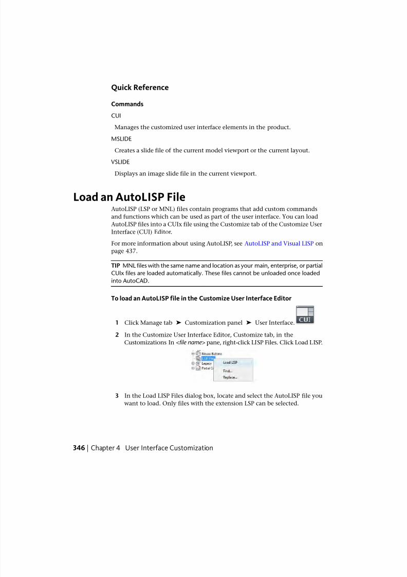
7/23/2019 Acad Customization
http://slidepdf.com/reader/full/acad-customization 354/553
Quick Reference
Commands
CUI
Manages the customized user interface elements in the product.
MSLIDE
Creates a slide file of the current model viewport or the current layout.
VSLIDE
Displays an image slide file in the current viewport.
Load an AutoLISP FileAutoLISP (LSP or MNL) files contain programs that add custom commands
and functions which can be used as part of the user interface. You can load
AutoLISP files into a CUIx file using the Customize tab of the Customize User
Interface (CUI) Editor.
For more information about using AutoLISP, see AutoLISP and Visual LISP on
page 437.
TIP MNL files with the same name and location as your main, enterprise, or partial
CUIx files are loaded automatically. These files cannot be unloaded once loaded
into AutoCAD.
To load an AutoLISP file in the Customize User Interface Editor
1 Click Manage tab ➤ Customization panel ➤ User Interface.
2 In the Customize User Interface Editor, Customize tab, in the
Customizations In <file name> pane, right-click LISP Files. Click Load LISP.
3 In the Load LISP Files dialog box, locate and select the AutoLISP file you
want to load. Only files with the extension LSP can be selected.
346 | Chapter 4 User Interface Customization
7/23/2019 Acad Customization
http://slidepdf.com/reader/full/acad-customization 355/553
TIP Even though files with the LSP extension can only be loaded using this
method, you can still load other types of custom program files. Use AutoCAD
commands such as NETLOAD, VBALOAD, or ARX to load other types of
custom program files.
4 Click Open.
5 In the Customize User Interface Editor, click Apply.
Quick Reference
Commands
APPLOAD
Loads and unloads applications and defines which applications to load atstartup.
ARX
Loads, unloads, and provides information about ObjectARX applications.
CUI
Manages the customized user interface elements in the product.
NETLOAD
Loads a .NET application.
VBALOAD
Loads a global VBA project into the current work session.
Customize WorkspacesYou can customize workspaces to create a drawing environment that displays
only those commands on the Quick Access toolbar, toolbars, menus, ribbon
tabs, and palettes that you select.
Overview of Workspace Customization
Customization options for workspaces include creating a workspace using the
Customize User Interface (CUI) Editor, changing the properties of a workspace,
and displaying a toolbar in all workspaces.
Customize Workspaces | 347
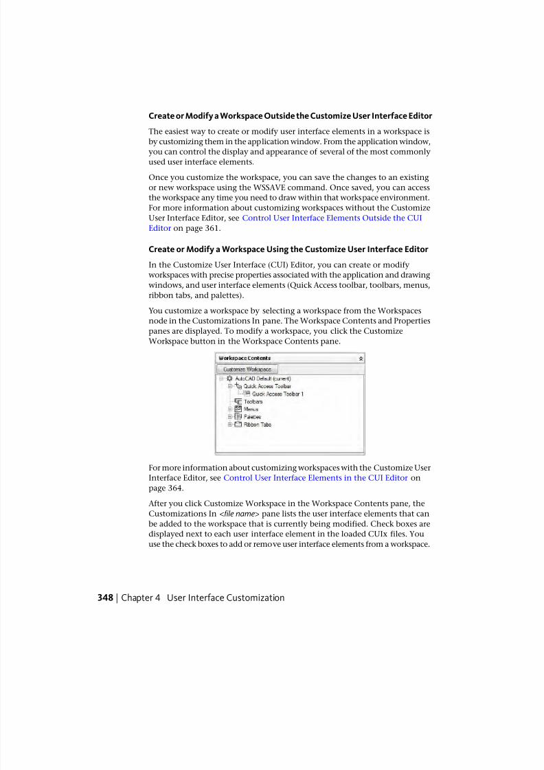
7/23/2019 Acad Customization
http://slidepdf.com/reader/full/acad-customization 356/553
Create or Modify a Workspace Outside the Customize User Interface Editor
The easiest way to create or modify user interface elements in a workspace isby customizing them in the application window. From the application window,
you can control the display and appearance of several of the most commonly
used user interface elements.
Once you customize the workspace, you can save the changes to an existing
or new workspace using the WSSAVE command. Once saved, you can access
the workspace any time you need to draw within that workspace environment.
For more information about customizing workspaces without the Customize
User Interface Editor, see Control User Interface Elements Outside the CUI
Editor on page 361.
Create or Modify a Workspace Using the Customize User Interface Editor
In the Customize User Interface (CUI) Editor, you can create or modify
workspaces with precise properties associated with the application and drawing
windows, and user interface elements (Quick Access toolbar, toolbars, menus,
ribbon tabs, and palettes).
You customize a workspace by selecting a workspace from the Workspaces
node in the Customizations In pane. The Workspace Contents and Properties
panes are displayed. To modify a workspace, you click the Customize
Workspace button in the Workspace Contents pane.
For more information about customizing workspaces with the Customize User
Interface Editor, see Control User Interface Elements in the CUI Editor on
page 364.
After you click Customize Workspace in the Workspace Contents pane, the
Customizations In <file name> pane lists the user interface elements that can
be added to the workspace that is currently being modified. Check boxes are
displayed next to each user interface element in the loaded CUIx files. You
use the check boxes to add or remove user interface elements from a workspace.
348 | Chapter 4 User Interface Customization
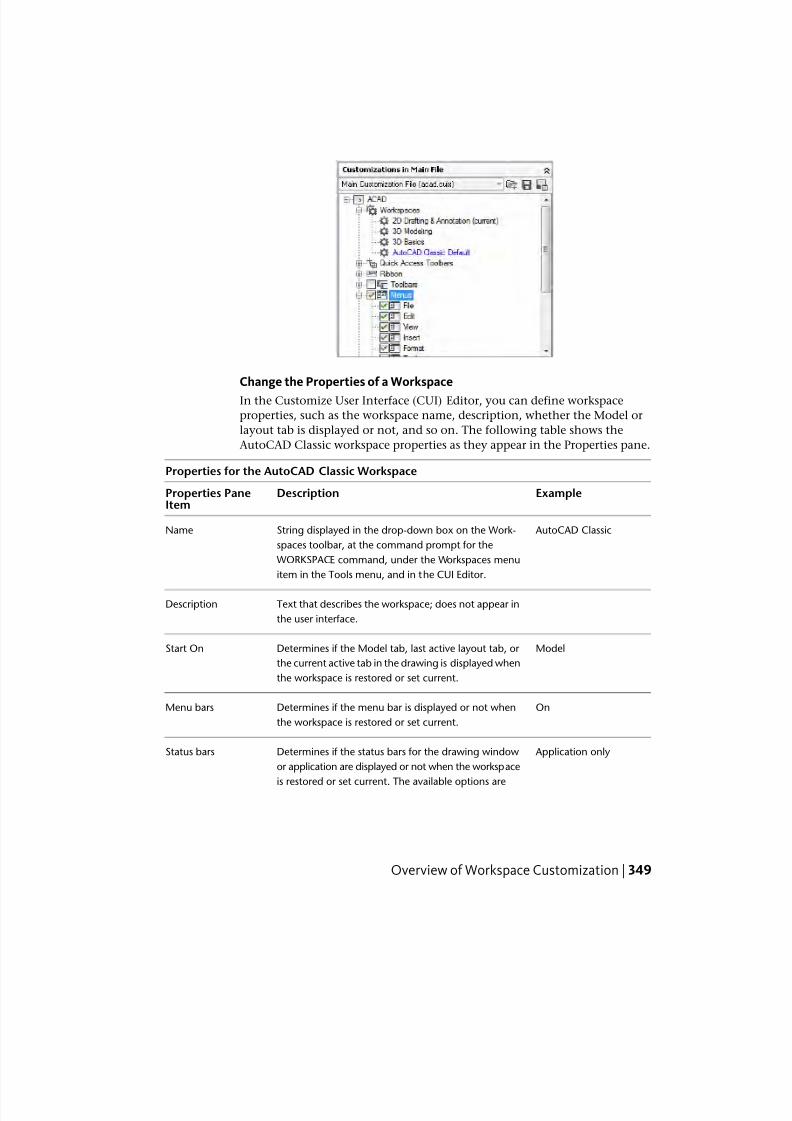
7/23/2019 Acad Customization
http://slidepdf.com/reader/full/acad-customization 357/553
Change the Properties of a Workspace
In the Customize User Interface (CUI) Editor, you can define workspace
properties, such as the workspace name, description, whether the Model or
layout tab is displayed or not, and so on. The following table shows the
AutoCAD Classic workspace properties as they appear in the Properties pane.
Properties for the AutoCAD Classic Workspace
ExampleDescriptionProperties PaneItem
AutoCAD ClassicString displayed in the drop-down box on the Work-
spaces toolbar, at the command prompt for the
Name
WORKSPACE command, under the Workspaces menu
item in the Tools menu, and in the CUI Editor.
Text that describes the workspace; does not appear in
the user interface.
Description
ModelDetermines if the Model tab, last active layout tab, or
the current active tab in the drawing is displayed when
the workspace is restored or set current.
Start On
OnDetermines if the menu bar is displayed or not when
the workspace is restored or set current.
Menu bars
Application onlyDetermines if the status bars for the drawing window
or application are displayed or not when the workspace
Status bars
is restored or set current. The available options are
Overview of Workspace Customization | 349
7/23/2019 Acad Customization
http://slidepdf.com/reader/full/acad-customization 358/553
Properties for the AutoCAD Classic Workspace
ExampleDescriptionProperties PaneItem
Application Only, All Off, All On, or Drawing Status Bar
Only.
OnDetermines if the Model/layout tabs are visible or not
in the drawing window when the workspace is restored
or set current.
Model/Layout tabs
Off Determines if the Screen menu is visible or not when
the workspace is restored or set current.
Screen menus
OnDetermines if the scroll bars are visible or not when the
workspace is restored or set current.
Scroll bars
Import a Workspace to a Main CUIx File
You can import a workspace to the main CUIx file using the Transfer tab of
the Customize User Interface (CUI) Editor. Workspaces in partially loaded
CUIx files must be transferred to the main CUIx file if you want to set that
workspace current.
Set the Default Workspace
Workspaces in a CUIx file can be marked as default. This identifies which
workspace in the CUIx file should be restored when the CUIx file is loaded
into the program the first time, or after the CUIx file has been loaded with
the CUILOAD command.
Set a Workspace Current
Once a workspace is created or modified, it must be set current before the
workspace can be used to control the current display of the user interface.
You set workspaces current through the user interface or the Customize User
Interface (CUI) Editor. From the user interface, you can set a workspace current
with the Workspaces toolbar, Workspace Switching button on the status bar,
Tools menu on the menu bar, and the WORKSPACE command.
You can also use the /w command line switch to set a workspace current when
you double-click the desktop shortcut to start AutoCAD. For more information
about command line switches, see Customize Startup in the User ’ s Guide .
350 | Chapter 4 User Interface Customization
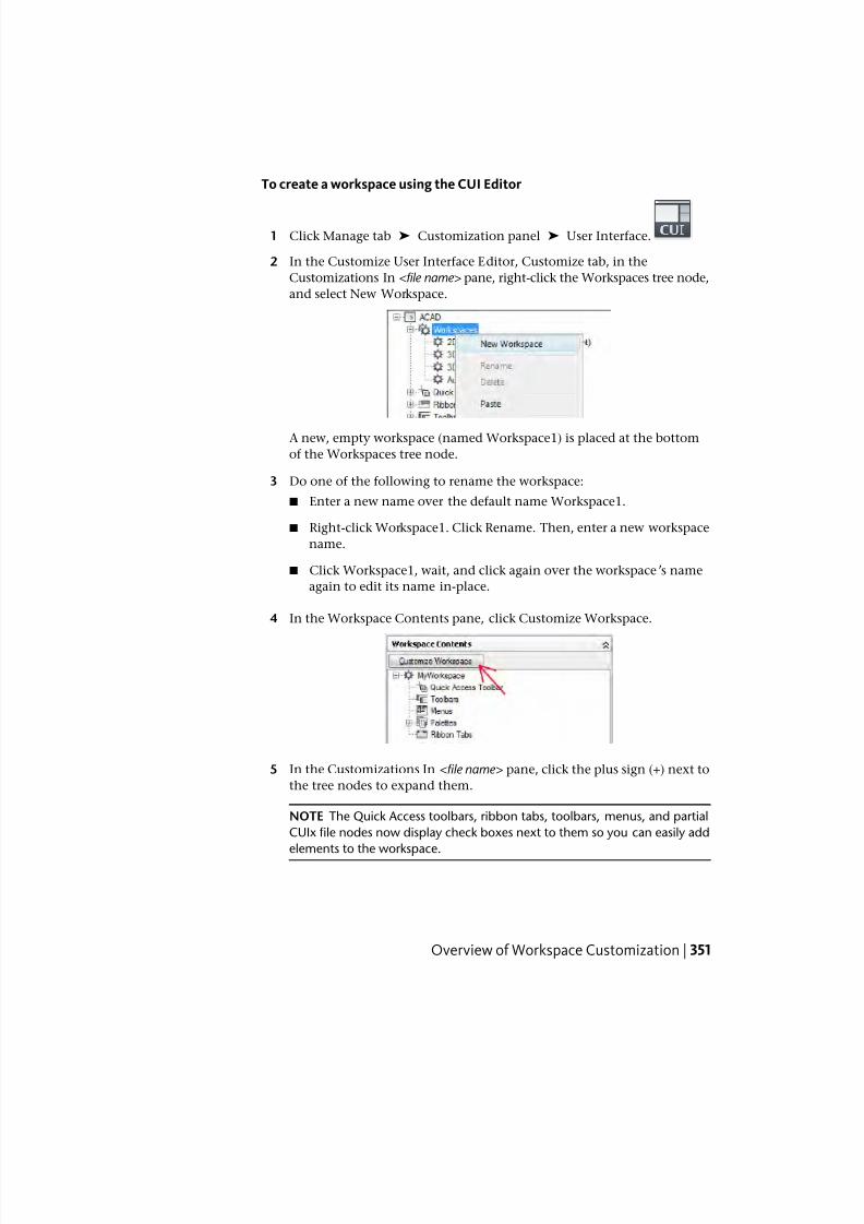
7/23/2019 Acad Customization
http://slidepdf.com/reader/full/acad-customization 359/553
To create a workspace using the CUI Editor
1 Click Manage tab ➤ Customization panel ➤ User Interface.
2 In the Customize User Interface Editor, Customize tab, in the
Customizations In <file name> pane, right-click the Workspaces tree node,
and select New Workspace.
A new, empty workspace (named Workspace1) is placed at the bottom
of the Workspaces tree node.
3 Do one of the following to rename the workspace:
■ Enter a new name over the default name Workspace1.
■ Right-click Workspace1. Click Rename. Then, enter a new workspace
name.
■ Click Workspace1, wait, and click again over the workspace’s name
again to edit its name in-place.
4 In the Workspace Contents pane, click Customize Workspace.
5 In the Customizations In <file name> pane, click the plus sign (+) next to
the tree nodes to expand them.
NOTE The Quick Access toolbars, ribbon tabs, toolbars, menus, and partial
CUIx file nodes now display check boxes next to them so you can easily add
elements to the workspace.
Overview of Workspace Customization | 351
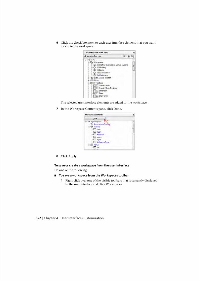
7/23/2019 Acad Customization
http://slidepdf.com/reader/full/acad-customization 360/553
6 Click the check box next to each user interface element that you want
to add to the workspace.
The selected user interface elements are added to the workspace.
7 In the Workspace Contents pane, click Done.
8 Click Apply.
To save or create a workspace from the user interface
Do one of the following:
■ To save a workspace from the Workspaces toolbar
1 Right-click over one of the visible toolbars that is currently displayed
in the user interface and click Workspaces.
352 | Chapter 4 User Interface Customization
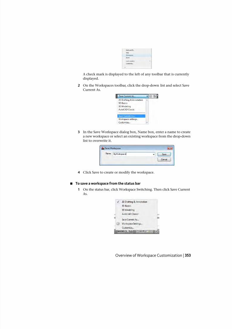
7/23/2019 Acad Customization
http://slidepdf.com/reader/full/acad-customization 361/553
A check mark is displayed to the left of any toolbar that is currently
displayed.
2 On the Workspaces toolbar, click the drop-down list and select Save
Current As.
3 In the Save Workspace dialog box, Name box, enter a name to create
a new workspace or select an existing workspace from the drop-down
list to overwrite it.
4 Click Save to create or modify the workspace.
■ To save a workspace from the status bar
1 On the status bar, click Workspace Switching. Then click Save Current
As.
Overview of Workspace Customization | 353
7/23/2019 Acad Customization
http://slidepdf.com/reader/full/acad-customization 362/553
2 In the Save Workspace dialog box, Name box, enter a name to create
a new workspace or select an existing workspace from the drop-down
list to overwrite it.
3 Click Save to create or modify the workspace.
NOTE You can also save a workspace from the Quick Access toolbar.
To change the properties of a workspace
1 Click Manage tab ➤ Customization panel ➤ User Interface.
2 In the Customize User Interface Editor, Customize tab, in the
Customizations In <file name> pane, click the workspace whose properties
you want to change.
3 In the Properties pane, do any of the following:
■ In the Name box, enter a name for the workspace.
■ In the Description box, enter a description.
■ In the Start On box, select an option (Model, Layout, Do Not Change).
■ In the Menu Bar box, select an option (Off, On).
■ In the Status Bar box, select an option (Application Only, All Off, All
On, Drawing Status Bar Only).
■ In the Model/Layout Tab box, select an option (On, Off, Do Not
Change).
■ In the Screen Menus box, select an option (On, Off, Do Not Change).
354 | Chapter 4 User Interface Customization
7/23/2019 Acad Customization
http://slidepdf.com/reader/full/acad-customization 363/553
■ In the Scroll Bars box, select an option (On, Off, Do Not Change).
4 Click Apply.
To duplicate a workspace
1 Click Manage tab ➤ Customization panel ➤ User Interface.
2 In the Customize User Interface Editor, Customize tab, in the
Customizations In <file name> pane, click the plus sign (+) next to
Workspaces to expand it.
3 Right-click the workspace you want to duplicate. Click Duplicate.
A duplicate of the workspace (named Copy of <workspace name>) is placed
at the bottom of the Workspaces tree node).
4 Do one of the following to rename the duplicate workspace:
■ Enter a new name over the default name Copy Of <workspace name>.
■ Right-click Copy Of <workspace name>. Click Rename. Enter a new
name for the workspace.
Overview of Workspace Customization | 355
7/23/2019 Acad Customization
http://slidepdf.com/reader/full/acad-customization 364/553
■ Click Copy Of <workspace name>, wait, and click again over the
workspace’s name again to edit its name in-place.
5 Modify the workspace as necessary.
6 Click Apply.
To set a workspace current from the user interface
Do one of the following:
■ To set a workspace current from the Workspaces toolbar
■ On the Workspaces toolbar, click the drop-down list and select the
workspace you want to set current.
If the Workspaces toolbar is not displayed, right-click over one of the
visible toolbars that is currently displayed in the user interface and
click Workspaces.
■ To set a workspace current from the status bar
■ On the status bar, click Workspace Switching. Then click the workspace
you want to set current
356 | Chapter 4 User Interface Customization
7/23/2019 Acad Customization
http://slidepdf.com/reader/full/acad-customization 365/553
NOTE You can also set a workspace from the Quick Access toolbar.
■ To set a workspace current from the Tools menu on the menu bar
■ On the menu bar, click Tools menu ➤ Workspaces ➤ select the
workspace you want to set current.
To set a workspace current from the CUI Editor
1 Click Manage tab ➤ Customization panel ➤ User Interface.
2 In the Customize User Interface Editor, Customize tab, in the
Customizations In <file name> pane, click the plus sign (+) next to
Workspaces to expand it.
3 Right-click the workspace you want to set current. Click Set Current.
4 Click Apply.
To restore the “classic” workspace
■ From the status bar, click Workspace Switching. Click AutoCAD Classic.
Overview of Workspace Customization | 357
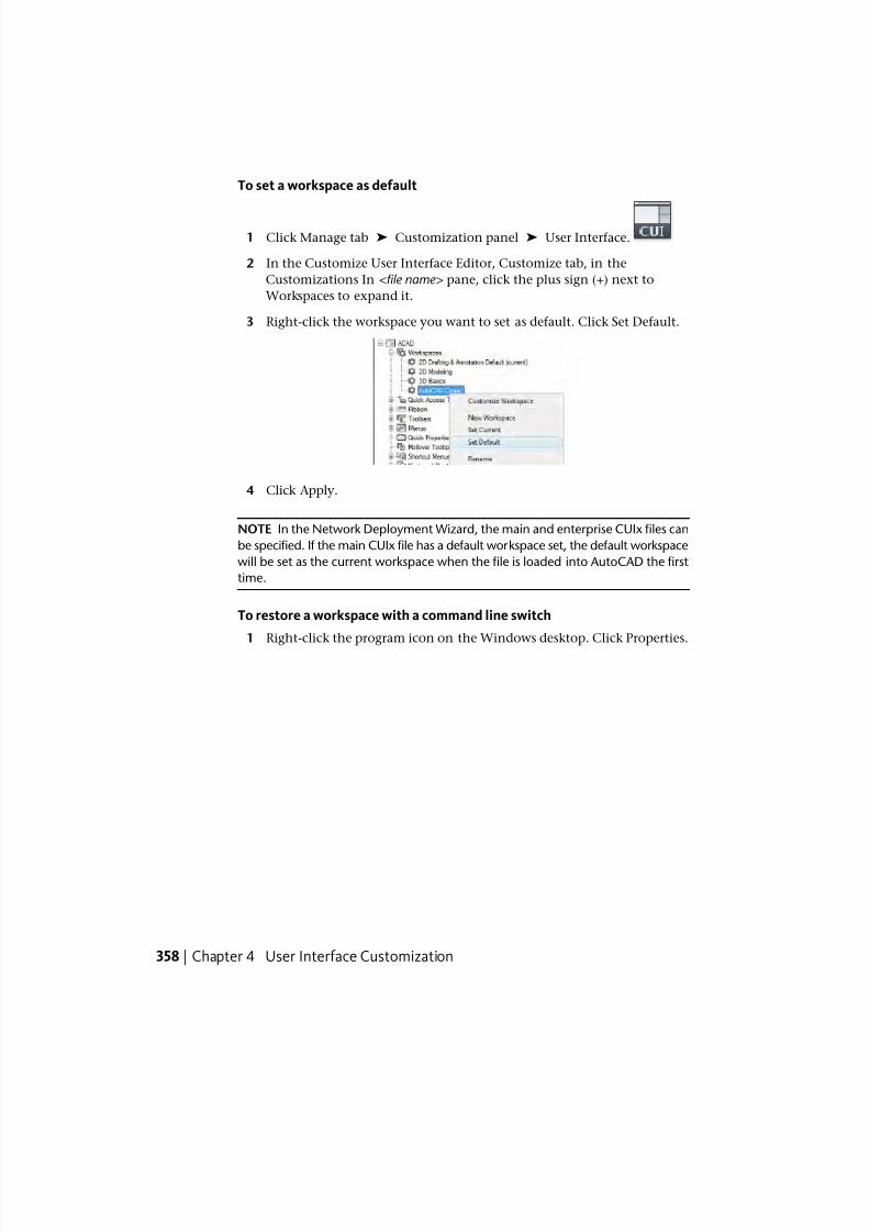
7/23/2019 Acad Customization
http://slidepdf.com/reader/full/acad-customization 366/553
To set a workspace as default
1 Click Manage tab ➤ Customization panel ➤ User Interface.
2 In the Customize User Interface Editor, Customize tab, in the
Customizations In <file name> pane, click the plus sign (+) next to
Workspaces to expand it.
3 Right-click the workspace you want to set as default. Click Set Default.
4 Click Apply.
NOTE In the Network Deployment Wizard, the main and enterprise CUIx files can
be specified. If the main CUIx file has a default workspace set, the default workspace
will be set as the current workspace when the file is loaded into AutoCAD the first
time.
To restore a workspace with a command line switch
1 Right-click the program icon on the Windows desktop. Click Properties.
358 | Chapter 4 User Interface Customization
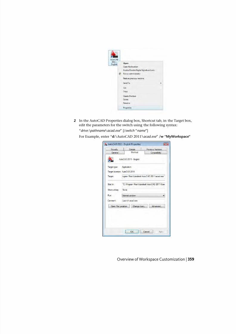
7/23/2019 Acad Customization
http://slidepdf.com/reader/full/acad-customization 367/553
2 In the AutoCAD Properties dialog box, Shortcut tab, in the Target box,
edit the parameters for the switch using the following syntax:
“drive :\pathname \acad.exe ” [/switch “name ”]
For Example, enter “d:\AutoCAD 2011\acad.exe ” /w “MyWorkspace”
Overview of Workspace Customization | 359
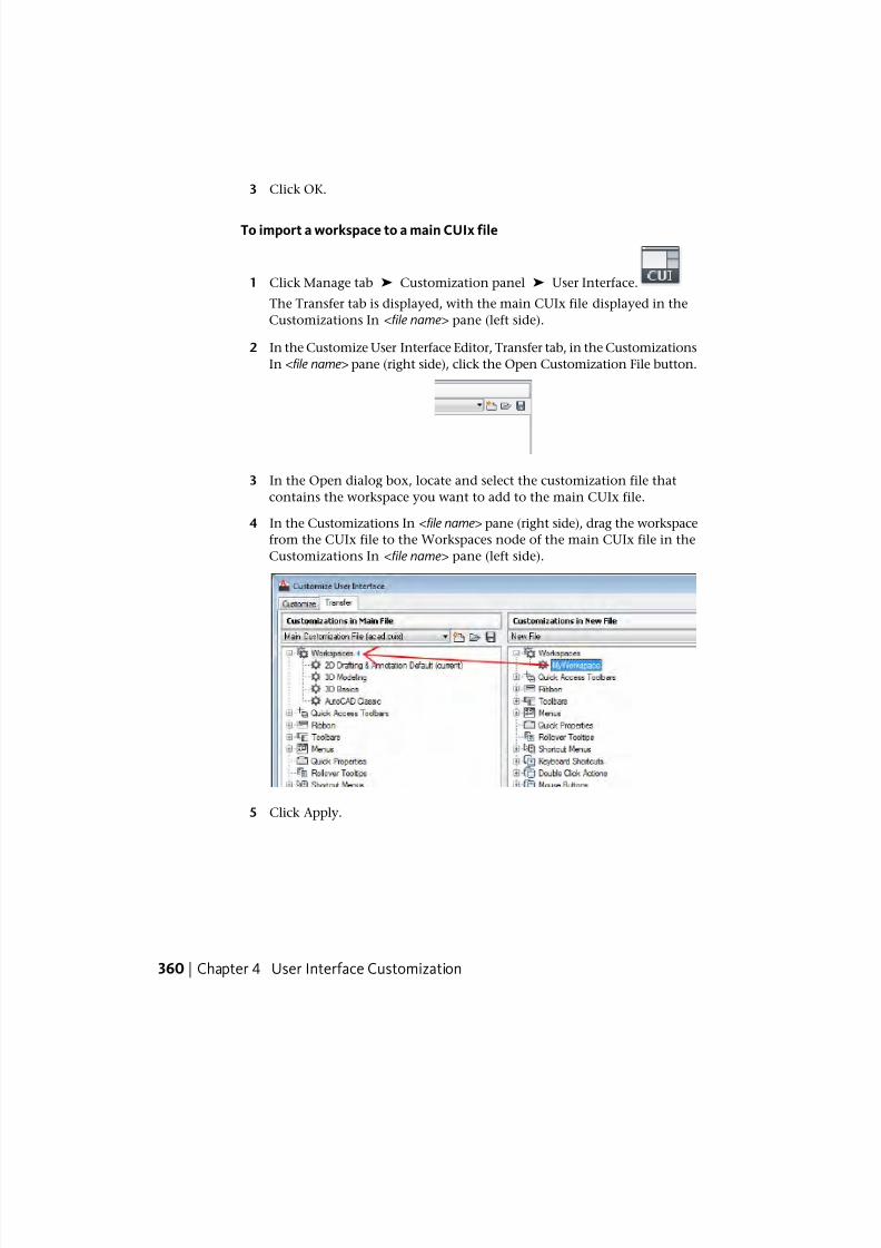
7/23/2019 Acad Customization
http://slidepdf.com/reader/full/acad-customization 368/553
3 Click OK.
To import a workspace to a main CUIx file
1 Click Manage tab ➤ Customization panel ➤ User Interface.
The Transfer tab is displayed, with the main CUIx file displayed in the
Customizations In <file name> pane (left side).
2 In the Customize User Interface Editor, Transfer tab, in the Customizations
In <file name> pane (right side), click the Open Customization File button.
3 In the Open dialog box, locate and select the customization file that
contains the workspace you want to add to the main CUIx file.
4 In the Customizations In <file name> pane (right side), drag the workspace
from the CUIx file to the Workspaces node of the main CUIx file in the
Customizations In <file name> pane (left side).
5 Click Apply.
360 | Chapter 4 User Interface Customization
7/23/2019 Acad Customization
http://slidepdf.com/reader/full/acad-customization 369/553
Quick Reference
Commands
CUI
Manages the customized user interface elements in the product.
CUIEXPORT
Exports customized settings from the main CUIx file to an enterprise or
partial CUIx file.
CUIIMPORT
Imports customized settings from an enterprise or partial CUIx file to the
main CUIx file.
CUILOADLoads a CUIx file.
CUIUNLOAD
Unloads a CUIx file.
WORKSPACE
Creates, modifies, and saves workspaces and makes a workspace current.
WSSAVE
Saves a workspace.
System Variables
WSCURRENT
Returns the current workspace name at the Command prompt and sets a
workspace to current.
Control User Interface Elements Outside the CUI EditorWorkspaces can be created and modified from the user interface with some
limitations.
With the CUI Editor, you can customize the following user interface elements
with a workspace:
■ Quick Access toolbar
Control User Interface Elements Outside the CUI Editor | 361
7/23/2019 Acad Customization
http://slidepdf.com/reader/full/acad-customization 370/553
■ Ribbon tabs
■ Toolbars
■ Palettes
Control the Display of the Quick Access Toolbar
Customization of the Quick Access toolbar outside the Customize User Interface
Editor is limited to controlling the placement of the Quick Access toolbar in
relation to the ribbon, and adding or removing commands. To place and
customize the Quick Access toolbar, you right-click the Quick Access toolbar
or click the Customize button located on the far right end of the Quick Access
toolbar.
The Customize button displays a menu where you add or remove the
commands currently assigned to the Quick Access toolbar. You can also addbuttons on the ribbon to the Quick Access toolbar. With the CUI Editor, you
can create new Quick Access toolbars, which you can assign to a workspace.
To create a new Quick Access toolbar, see Quick Access Toolbars on page 194.
Control the Display of the Ribbon Panels and Tabs on the Ribbon
You can control the display of ribbon panels and tabs from the ribbon shortcut
menu. You can display one of the ribbon tabs assigned to the current workspace
or one of the ribbon panels assigned to the active ribbon tab. To control which
ribbon tabs and panels are assigned to the current workspace, see Control User
Interface Elements in the CUI Editor on page 364.
Control the Display of Toolbars
You can display toolbars with the toolbar shortcut menu and the Tools menu
on the menu bar. You select the toolbar you want to display. On the Tools
menu, the Toolbars submenu contains all the toolbars in the loaded CUIx
files.
With the CUI Editor, you can create new toolbars, which can be assigned to
and displayed with a workspace. Along with creating new toolbars, you can
also modify existing toolbars to display the commands you frequently use.
For information about creating and modifying toolbars, see Create and Edit
Toolbars on page 248.
Control the Display of Palettes
Palettes are displayed using the ribbon, the Tools menu on the menu bar, orby entering a command. Once a palette is displayed, you can control many
362 | Chapter 4 User Interface Customization
7/23/2019 Acad Customization
http://slidepdf.com/reader/full/acad-customization 371/553
of the visual aspects of a palette from the application window. You can specify
the position, size, transparency, and docking of a palette. For information
about controlling the display of a palette, see Specify the Behavior of DockableWindows in the User ’ s Guide .
See also:
■ Control User Interface Elements in the CUI Editor on page 364
■ To display the Quick Access toolbar above or below the ribbon from the
user interface on page 363 (Procedure)
■ To display toolbars from the user interface on page 363 (Procedure)
■ To control the display of ribbon tabs and panels on the ribbon from the
user interface on page 363 (Procedure)
■ To display palettes from the user interface on page 364 (Procedure)
To display the Quick Access toolbar above or below the ribbon from the userinterface
1 Right-click on the Quick Access toolbar.
2 Do one of the following:
■ Click Show Quick Access Toolbar Below the Ribbon to display the
Quick Access toolbar below the ribbon.
■ Click Show Quick Access Toolbar Above the Ribbon to display the
Quick Access toolbar above the ribbon.
To display toolbars from the user interface
Do one of the following:
■ On the menu bar, click Tools menu ➤ Toolbars, and click one of the listed
toolbars.
If the menu bar is not displayed, on the Quick Access toolbar, click the
Customize button. Click Show Menu Bar.
■ Right-click a visible toolbar, and click one of the listed toolbars.
To control the display of ribbon tabs and panels on the ribbon from the userinterface
1 Right-click on the ribbon.
Control User Interface Elements Outside the CUI Editor | 363
7/23/2019 Acad Customization
http://slidepdf.com/reader/full/acad-customization 372/553
2 Do one of the following:
■ Click Tabs, and click the ribbon tab to display or hide.
■ Click Panels, and click the ribbon panel to display or hide.
To display palettes from the user interface
Do one of the following:
■ On the ribbon, View tab ➤ Palettes panel, and click the buttons to display
the desired palette.
■ On the menu bar, click Tools menu ➤ Palettes, and click the desired
palette.
■ At the Command prompt, enter the command to display the desired
palette and press Enter.
Quick Reference
Commands
CUI
Manages the customized user interface elements in the product.
System Variables
MENUBAR
Controls the display of the menu bar.
Control User Interface Elements in the CUI EditorThe Customize User Interface (CUI) Editor provides a wide range of options
to create and modify all the content that can be displayed with a workspaces.
With the CUI Editor, you can customize the following user interface elements
with a workspace:
■ Application and drawing windows
■ Quick Access toolbar
■ Ribbon tabs
364 | Chapter 4 User Interface Customization
7/23/2019 Acad Customization
http://slidepdf.com/reader/full/acad-customization 373/553
■ Toolbars
■ Menus
■ Palettes
Control the Display of User Interface Elements on the Application andDrawing Windows
Workspaces control the display of user interface elements such as toolbars
and the menu bar. While a workspace primarily provides toolbars, menus,
ribbon tabs, and palettes, you can also use a workspace to control user interface
elements for the application and drawing windows. A workspace can control
the following:
■ Which layout tab is set current when a drawing is opened
■ Display of the menu bar
■ Display of the application and drawing status bars
■ If layout tabs are displayed along the bottom of the drawing window.
■ Display of the legacy screen menu
■ Display of scroll bars in the drawing window
Control the Display of the Quick Access Toolbar
The Quick Access toolbar that is displayed on the application window is
controlled by the current workspace. While a workspace does not directly
control which commands are displayed on the Quick Access toolbar, it doescontrol which Quick Access toolbar in the loaded CUIx files is displayed. For
information about creating and editing Quick Access toolbars, see Quick Access
Toolbars on page 194.
Control the Display of Ribbon Tabs and Panels on the Ribbon
The display and order of ribbon tabs and panels on the ribbon are controlled
through workspaces. You add and specify the order of ribbon tabs and their
associated panels in the Workspace Contents pane. You add ribbon panels to
a ribbon tab through the Customizations In <file name > pane.
After you assign ribbon tabs to a workspace, you can control the default display
and behavior of both ribbon tabs and panels through the Properties pane.
From the Properties pane, you can set the Tool Palette Group for a ribbon taband orientation and resize order for a ribbon panel. For information about
Control User Interface Elements in the CUI Editor | 365
7/23/2019 Acad Customization
http://slidepdf.com/reader/full/acad-customization 374/553
creating and editing ribbon content, see Ribbon on page 201 under Customize
User Interface Elements on page 191.
Control the Display of Toolbars
You can control which toolbars are displayed and how they are positioned in
the application window (if they are floating or docked, and where they are in
the application window). You add the toolbars through the Workspace
Contents pane, and control the appearance of the toolbars in the Properties
pane. For information about creating and editing toolbars, see Toolbars on
page 248 under Customize User Interface Elements on page 191.
Control the Display of Menus on the Menu Bar
Menus and the order in which they are displayed on the menu bar can only
be controlled through the Workspace Contents pane. By default the menu
bar is not displayed when the ribbon is. Set the system variable MENUBAR to1 to display the menu bar above the ribbon. You can also set the Menu Bar
property for a workspace to On to display the menu bar each time a workspace
is set current. For information about creating and editing pull-down menus,
see Pull-down and Shortcut Menus on page 270 under Customize User Interface
Elements on page 191.
Control the Display of Palettes
You set up a workspace to control the display, position, and appearance of
palettes in the application window. They can be floating or docked. Unlike
ribbon panels, ribbon tabs, and menus, palettes are available in any workspace.
You can turn palettes on or off with a workspace. The display properties of
palettes are modified through the Workspace Contents and Properties pane.
For information about controlling palettes with workspaces, see Control the
Appearance of Palettes on page 380.
See also:
■ To display a Quick Access toolbar on page 367 (Procedure)
■ To display the Quick Access toolbar above or below the ribbon from the
CUI Editor on page 368 (Procedure)
■ To display ribbon tabs from the CUI Editor on page 369 (Procedure)
■ To reposition a ribbon tab on the ribbon on page 370 (Procedure)
■
To reposition a ribbon panel on a ribbon tab on page 371 (Procedure)
366 | Chapter 4 User Interface Customization
7/23/2019 Acad Customization
http://slidepdf.com/reader/full/acad-customization 375/553
■ To control the display of ribbon tabs on the ribbon on page 372 (Procedure)
■ To control the display of ribbon panels for a ribbon tab on page 373(Procedure)
■ To associate a tool palette group with a ribbon tab on page 373 (Procedure)
■ To display toolbars using the CUI Editor on page 374 (Procedure)
■ To change the properties of a toolbar on page 376 (Procedure)
■ To display menus on the menu bar on page 377 (Procedure)
■ To reposition menus on the menu bar on page 378 (Procedure)
■ To display a palette using the CUI Editor on page 379 (Procedure)
To display a Quick Access toolbar
1 Click Manage tab ➤ Customization panel ➤ User Interface.
2 In the Customize User Interface Editor, Customize tab, in the
Customizations In <file name> pane, click the plus sign (+) next to the
Workspaces node to expand it.
3 Select the workspace that you want to modify.
4 In the Workspace Contents pane, click Customize Workspace.
5 In the Customizations In <file name> pane, click the plus sign (+) next to
the Quick Access Toolbars tree node or Partial Customization Files tree
node to expand it.
Control User Interface Elements in the CUI Editor | 367
7/23/2019 Acad Customization
http://slidepdf.com/reader/full/acad-customization 376/553
6 Click the check box next to the Quick Access toolbar to add it to the
workspace.
7 In the Workspace Contents pane, click Done.
NOTE Make sure to set the workspace current to ensure the changes are
displayed.
8 Click Apply.
To display the Quick Access toolbar above or below the ribbon from the CUIEditor
1 Click Manage tab ➤ Customization panel ➤ User Interface.
2 In the Customize User Interface Editor, Customize tab, in the
Customizations In <file name> pane, click the plus sign (+) next to the
Workspaces node to expand it.
3 Select the workspace that you want to modify.
368 | Chapter 4 User Interface Customization
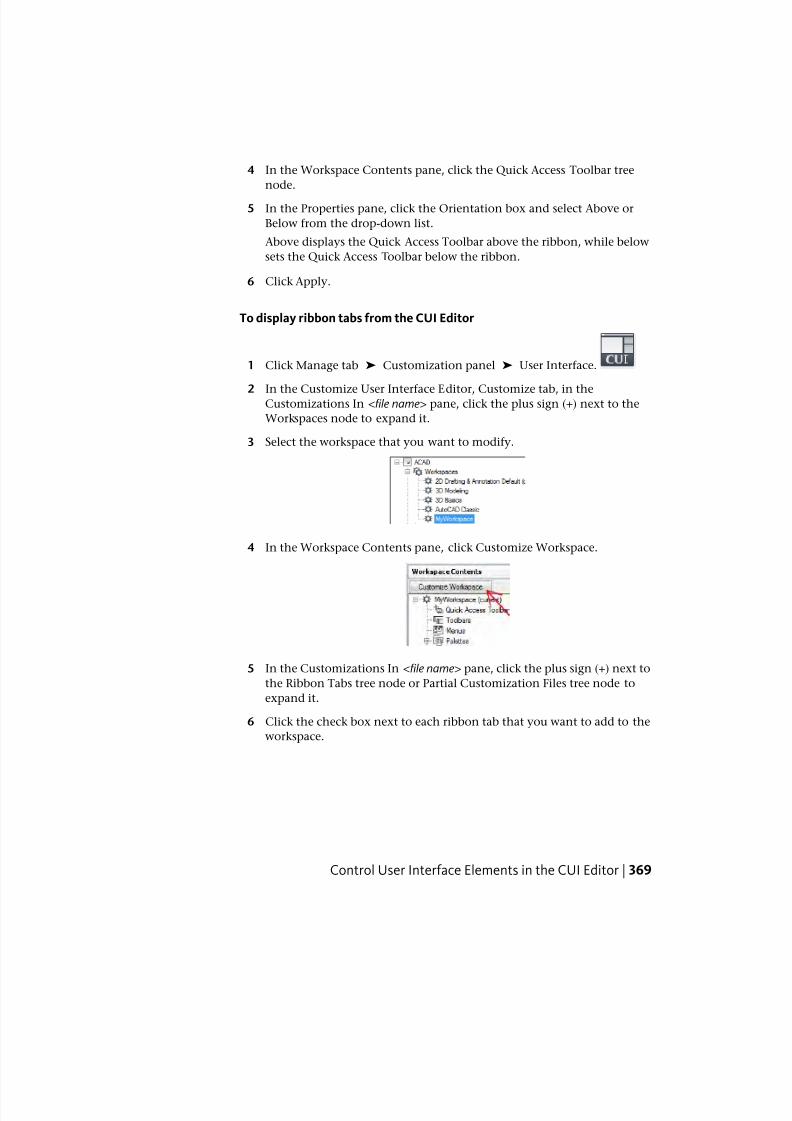
7/23/2019 Acad Customization
http://slidepdf.com/reader/full/acad-customization 377/553
4 In the Workspace Contents pane, click the Quick Access Toolbar tree
node.
5 In the Properties pane, click the Orientation box and select Above or
Below from the drop-down list.
Above displays the Quick Access Toolbar above the ribbon, while below
sets the Quick Access Toolbar below the ribbon.
6 Click Apply.
To display ribbon tabs from the CUI Editor
1 Click Manage tab ➤ Customization panel ➤ User Interface.
2 In the Customize User Interface Editor, Customize tab, in theCustomizations In <file name> pane, click the plus sign (+) next to the
Workspaces node to expand it.
3 Select the workspace that you want to modify.
4 In the Workspace Contents pane, click Customize Workspace.
5 In the Customizations In <file name> pane, click the plus sign (+) next to
the Ribbon Tabs tree node or Partial Customization Files tree node to
expand it.
6 Click the check box next to each ribbon tab that you want to add to the
workspace.
Control User Interface Elements in the CUI Editor | 369
7/23/2019 Acad Customization
http://slidepdf.com/reader/full/acad-customization 378/553
In the Workspace Contents pane, the selected elements are added to the
workspace.
7 In the Workspace Contents pane, click Done.
NOTE Make sure to set the workspace current to ensure the changes are
displayed.
8 Click Apply.
To reposition a ribbon tab on the ribbon
1 Click Manage tab ➤ Customization panel ➤ User Interface.
2 In the Customize User Interface Editor, Customize tab, in the
Customizations In <file name> pane, click the plus sign (+) next to the
Workspaces node to expand it.
3 Select the workspace that has the ribbon tab you want to reposition.
370 | Chapter 4 User Interface Customization
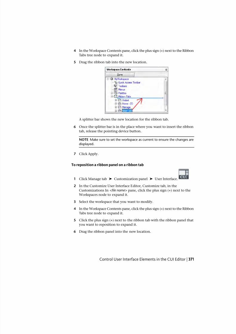
7/23/2019 Acad Customization
http://slidepdf.com/reader/full/acad-customization 379/553
4 In the Workspace Contents pane, click the plus sign (+) next to the Ribbon
Tabs tree node to expand it.
5 Drag the ribbon tab into the new location.
A splitter bar shows the new location for the ribbon tab.
6 Once the splitter bar is in the place where you want to insert the ribbon
tab, release the pointing device button.
NOTE Make sure to set the workspace as current to ensure the changes are
displayed.
7 Click Apply.
To reposition a ribbon panel on a ribbon tab
1 Click Manage tab ➤ Customization panel ➤ User Interface.
2 In the Customize User Interface Editor, Customize tab, in the
Customizations In <file name> pane, click the plus sign (+) next to the
Workspaces node to expand it.
3 Select the workspace that you want to modify.
4 In the Workspace Contents pane, click the plus sign (+) next to the Ribbon
Tabs tree node to expand it.
5 Click the plus sign (+) next to the ribbon tab with the ribbon panel that
you want to reposition to expand it.
6 Drag the ribbon panel into the new location.
Control User Interface Elements in the CUI Editor | 371
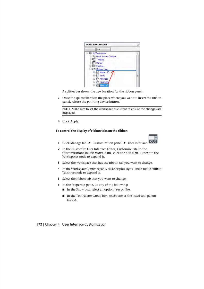
7/23/2019 Acad Customization
http://slidepdf.com/reader/full/acad-customization 380/553
A splitter bar shows the new location for the ribbon panel.
7 Once the splitter bar is in the place where you want to insert the ribbon
panel, release the pointing device button.
NOTE Make sure to set the workspace as current to ensure the changes are
displayed.
8 Click Apply.
To control the display of ribbon tabs on the ribbon
1 Click Manage tab ➤ Customization panel ➤ User Interface.
2 In the Customize User Interface Editor, Customize tab, in the
Customizations In <file name> pane, click the plus sign (+) next to theWorkspaces node to expand it.
3 Select the workspace that has the ribbon tab you want to change.
4 In the Workspace Contents pane, click the plus sign (+) next to the Ribbon
Tabs tree node to expand it.
5 Select the ribbon tab that you want to change.
6 In the Properties pane, do any of the following:
■ In the Show box, select an option (Yes or No).
■ In the ToolPalette Group box, select one of the listed tool palette
groups.
372 | Chapter 4 User Interface Customization
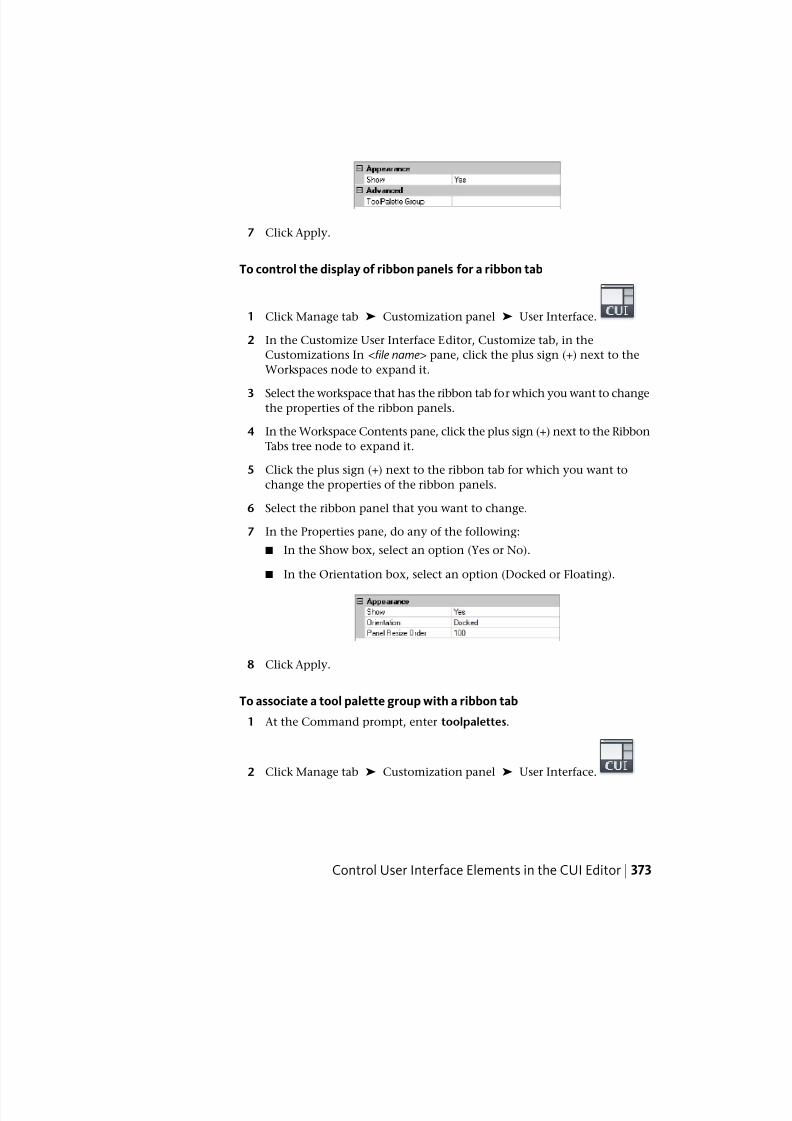
7/23/2019 Acad Customization
http://slidepdf.com/reader/full/acad-customization 381/553
7 Click Apply.
To control the display of ribbon panels for a ribbon tab
1 Click Manage tab ➤ Customization panel ➤ User Interface.
2 In the Customize User Interface Editor, Customize tab, in the
Customizations In <file name> pane, click the plus sign (+) next to the
Workspaces node to expand it.
3 Select the workspace that has the ribbon tab for which you want to changethe properties of the ribbon panels.
4 In the Workspace Contents pane, click the plus sign (+) next to the Ribbon
Tabs tree node to expand it.
5 Click the plus sign (+) next to the ribbon tab for which you want to
change the properties of the ribbon panels.
6 Select the ribbon panel that you want to change.
7 In the Properties pane, do any of the following:
■ In the Show box, select an option (Yes or No).
■ In the Orientation box, select an option (Docked or Floating).
8 Click Apply.
To associate a tool palette group with a ribbon tab
1 At the Command prompt, enter toolpalettes.
2 Click Manage tab ➤ Customization panel ➤ User Interface.
Control User Interface Elements in the CUI Editor | 373
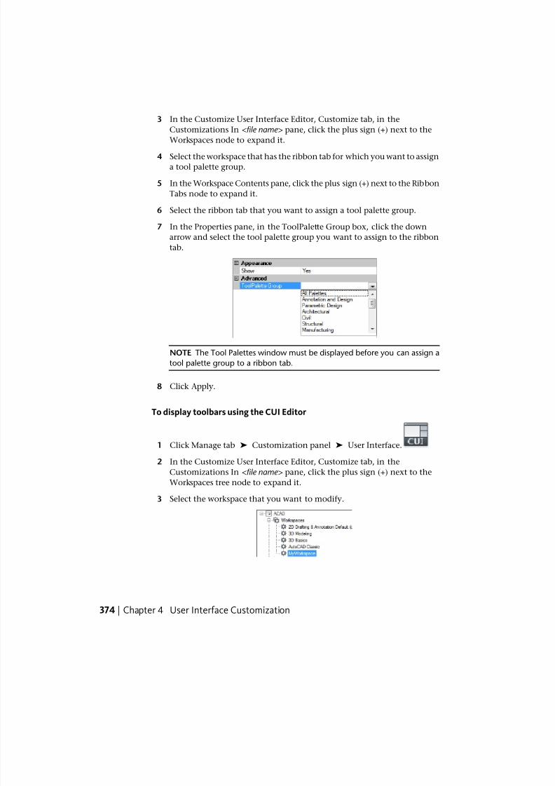
7/23/2019 Acad Customization
http://slidepdf.com/reader/full/acad-customization 382/553
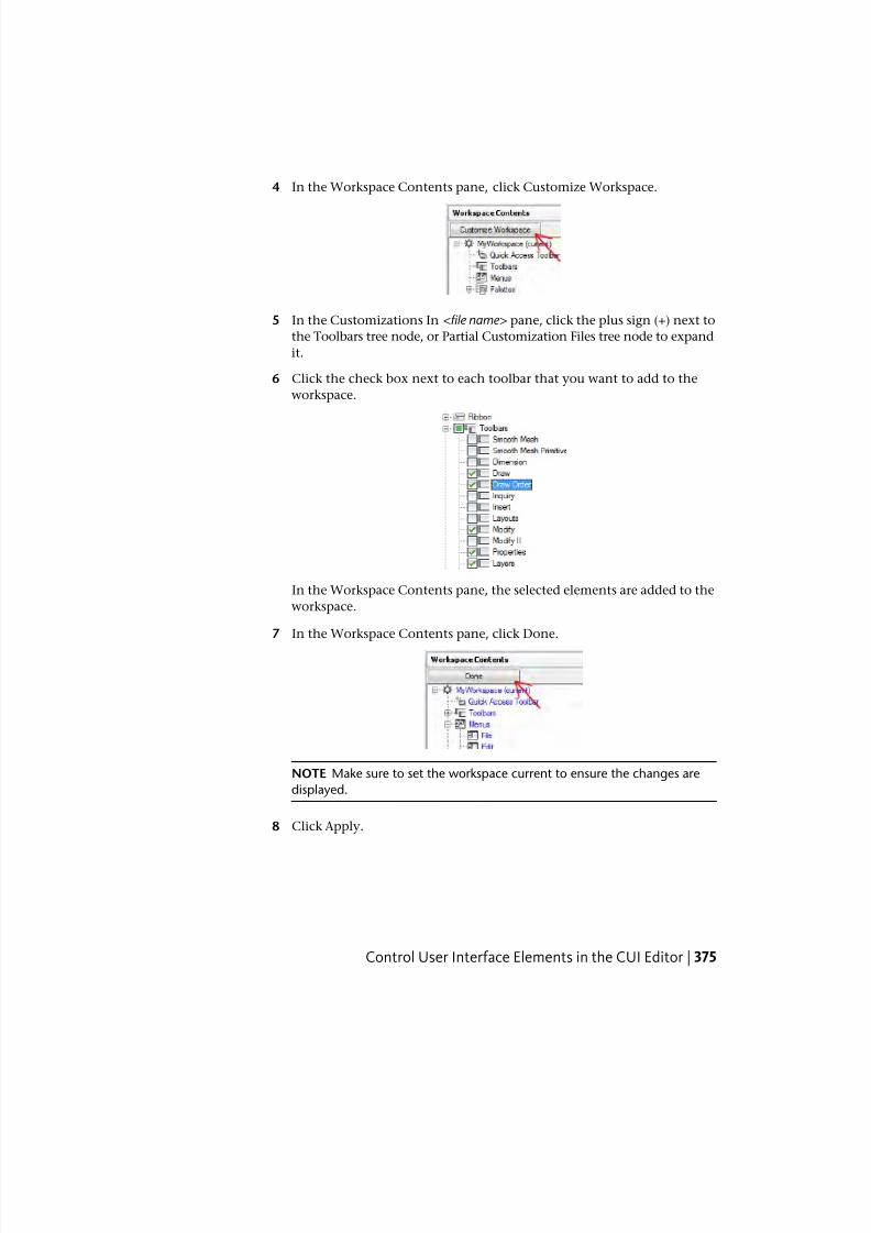
7/23/2019 Acad Customization
http://slidepdf.com/reader/full/acad-customization 383/553
4 In the Workspace Contents pane, click Customize Workspace.
5 In the Customizations In <file name> pane, click the plus sign (+) next to
the Toolbars tree node, or Partial Customization Files tree node to expand
it.
6 Click the check box next to each toolbar that you want to add to the
workspace.
In the Workspace Contents pane, the selected elements are added to the
workspace.
7 In the Workspace Contents pane, click Done.
NOTE Make sure to set the workspace current to ensure the changes are
displayed.
8 Click Apply.
Control User Interface Elements in the CUI Editor | 375
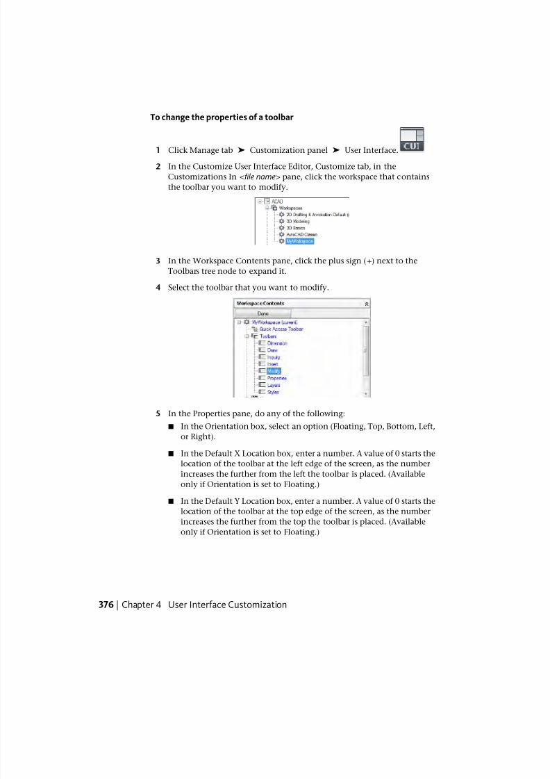
7/23/2019 Acad Customization
http://slidepdf.com/reader/full/acad-customization 384/553
To change the properties of a toolbar
1 Click Manage tab ➤ Customization panel ➤ User Interface.
2 In the Customize User Interface Editor, Customize tab, in the
Customizations In <file name> pane, click the workspace that contains
the toolbar you want to modify.
3 In the Workspace Contents pane, click the plus sign (+) next to the
Toolbars tree node to expand it.
4 Select the toolbar that you want to modify.
5 In the Properties pane, do any of the following:
■ In the Orientation box, select an option (Floating, Top, Bottom, Left,
or Right).
■ In the Default X Location box, enter a number. A value of 0 starts the
location of the toolbar at the left edge of the screen, as the number
increases the further from the left the toolbar is placed. (Available
only if Orientation is set to Floating.)
■ In the Default Y Location box, enter a number. A value of 0 starts the
location of the toolbar at the top edge of the screen, as the number
increases the further from the top the toolbar is placed. (Available
only if Orientation is set to Floating.)
376 | Chapter 4 User Interface Customization
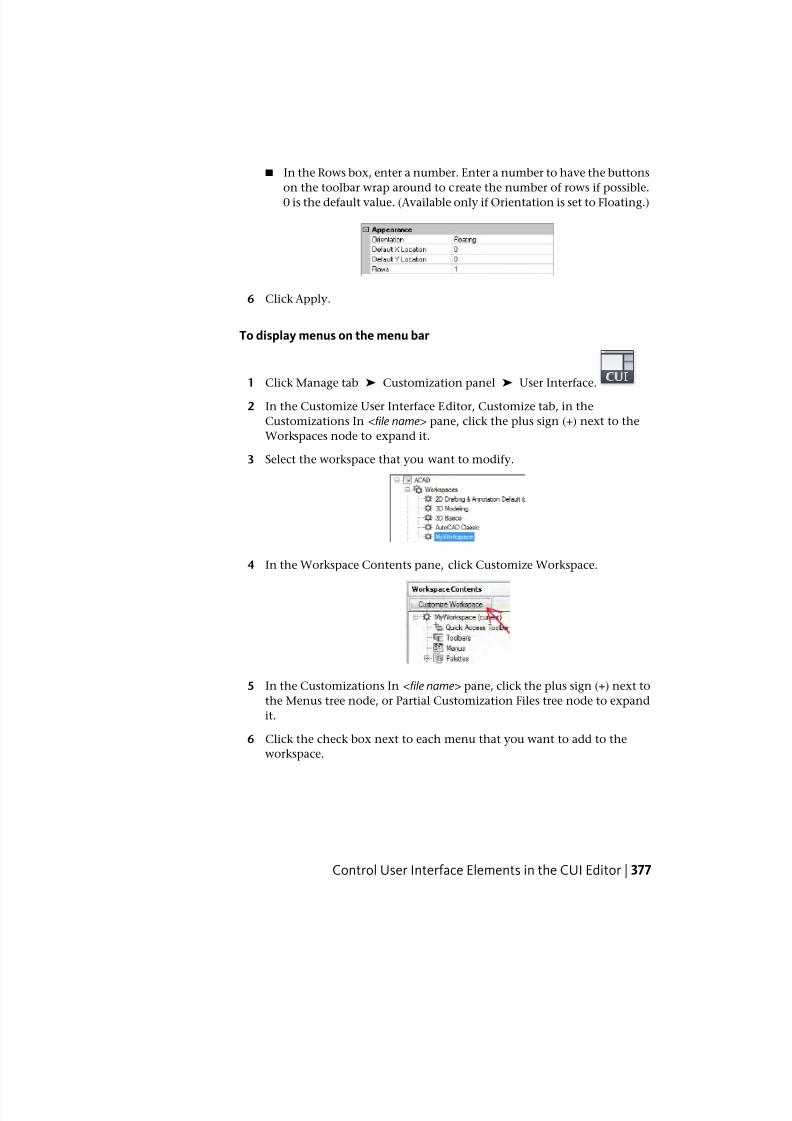
7/23/2019 Acad Customization
http://slidepdf.com/reader/full/acad-customization 385/553
■ In the Rows box, enter a number. Enter a number to have the buttons
on the toolbar wrap around to create the number of rows if possible.
0 is the default value. (Available only if Orientation is set to Floating.)
6 Click Apply.
To display menus on the menu bar
1 Click Manage tab ➤ Customization panel ➤ User Interface.
2 In the Customize User Interface Editor, Customize tab, in the
Customizations In <file name> pane, click the plus sign (+) next to the
Workspaces node to expand it.
3 Select the workspace that you want to modify.
4 In the Workspace Contents pane, click Customize Workspace.
5 In the Customizations In <file name> pane, click the plus sign (+) next to
the Menus tree node, or Partial Customization Files tree node to expand
it.
6 Click the check box next to each menu that you want to add to the
workspace.
Control User Interface Elements in the CUI Editor | 377
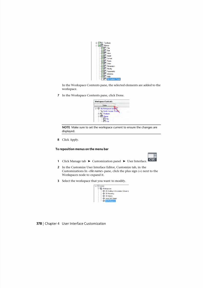
7/23/2019 Acad Customization
http://slidepdf.com/reader/full/acad-customization 386/553
In the Workspace Contents pane, the selected elements are added to the
workspace.
7 In the Workspace Contents pane, click Done.
NOTE Make sure to set the workspace current to ensure the changes are
displayed.
8 Click Apply.
To reposition menus on the menu bar
1 Click Manage tab ➤ Customization panel ➤ User Interface.
2 In the Customize User Interface Editor, Customize tab, in the
Customizations In <file name> pane, click the plus sign (+) next to the
Workspaces node to expand it.
3 Select the workspace that you want to modify.
378 | Chapter 4 User Interface Customization
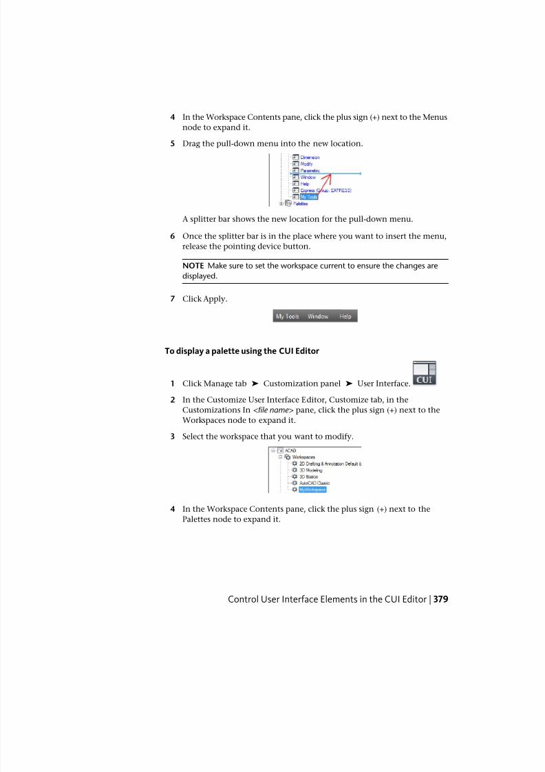
7/23/2019 Acad Customization
http://slidepdf.com/reader/full/acad-customization 387/553
4 In the Workspace Contents pane, click the plus sign (+) next to the Menus
node to expand it.
5 Drag the pull-down menu into the new location.
A splitter bar shows the new location for the pull-down menu.
6 Once the splitter bar is in the place where you want to insert the menu,
release the pointing device button.
NOTE Make sure to set the workspace current to ensure the changes are
displayed.
7 Click Apply.
To display a palette using the CUI Editor
1 Click Manage tab ➤ Customization panel ➤ User Interface.
2 In the Customize User Interface Editor, Customize tab, in the
Customizations In <file name> pane, click the plus sign (+) next to the
Workspaces node to expand it.
3 Select the workspace that you want to modify.
4 In the Workspace Contents pane, click the plus sign (+) next to the
Palettes node to expand it.
Control User Interface Elements in the CUI Editor | 379
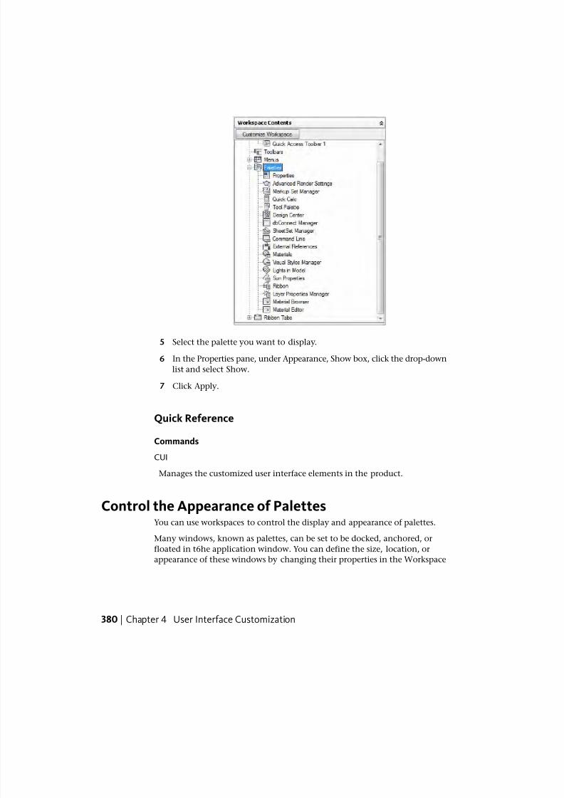
7/23/2019 Acad Customization
http://slidepdf.com/reader/full/acad-customization 388/553
5 Select the palette you want to display.
6 In the Properties pane, under Appearance, Show box, click the drop-down
list and select Show.
7 Click Apply.
Quick Reference
Commands
CUI
Manages the customized user interface elements in the product.
Control the Appearance of PalettesYou can use workspaces to control the display and appearance of palettes.
Many windows, known as palettes, can be set to be docked, anchored, or
floated in t6he application window. You can define the size, location, or
appearance of these windows by changing their properties in the Workspace
380 | Chapter 4 User Interface Customization
7/23/2019 Acad Customization
http://slidepdf.com/reader/full/acad-customization 389/553
Contents pane of the Customize User Interface (CUI) Editor. These dockable
windows include:
■ Advanced Render Settings■ Command Line
■ dbConnect Manager ■ DesignCenter
■ Lights in Model■ External References
■ Materials■ Layer Properties Manager
■ Sheet Set Manager ■ Markup Set Manager
■ Sun Properties■ Properties
■ Visual Styles Manager ■ QuickCalc
■ Ribbon
■ Tool Palette
The following table shows the properties as they appear in the Properties pane
for a palette in the CUI Editor and as an example, the default values of the
Tool Palettes window in the AutoCAD Classic workspace.
Properties for the Tool Palettes window under the AutoCAD Classic workspace
ExampleDescriptionProperties paneitem
Yes Visibility state of the palette. The available options are
No, Yes, or Do Not Change. Do Not Change keeps the
Show
last used state of the palette when the workspace is
restored or set current.
FloatingThe on screen docking or floating state of the palette.
The available options are Floating, Top, Bottom, Left,
Orientation
Right, or Do Not Change. Do Not Change keeps the
last used state of the palette when the workspace is
restored or set current. Some palettes like the Com-
mand Line also support a dock location of Top and
Bottom.
YesControls if the user can dock the palette by dragging
it to one of the designated docking areas. The available
Allow Docking
options are No, Yes, or Do Not Change. Do Not
Change maintains the last used setting for the palette
when the workspace is restored or set current.
Control the Appearance of Palettes | 381
7/23/2019 Acad Customization
http://slidepdf.com/reader/full/acad-customization 390/553
Properties for the Tool Palettes window under the AutoCAD Classic workspace
ExampleDescriptionProperties paneitem
Off Controls if the palette rolls up when not in use. The
available options are On, Off, or Do Not Change. Do
Auto Hide
Not Change maintains the last used setting for the
palette when the workspace is restored or set current.
NoControls if the palette appears transparent. The avail-
able options are No, Yes, or Do Not Change. Do Not
Use Transparency
Change maintains the last used setting for the palette
when the workspace is restored or set current.
0Controls how opaque the palette is displayed. The
valid range is 0 through 100.
Transparency Amount
All PalettesControls which of the user defined palette groups
should be displayed.
Default Group
598Determines how tall the palette is when it is floating.Height
172Determines how wide the palette is when it is floating. Width
See also:
■ To change the properties of a palette on page 382 (Procedure)
To change the properties of a palette
1 Click Manage tab ➤ Customization panel ➤ User Interface.
2 In the Customize User Interface Editor, Customize tab, in the
Customizations In <file name> pane, click the workspace that contains
the palette you want to modify.
382 | Chapter 4 User Interface Customization
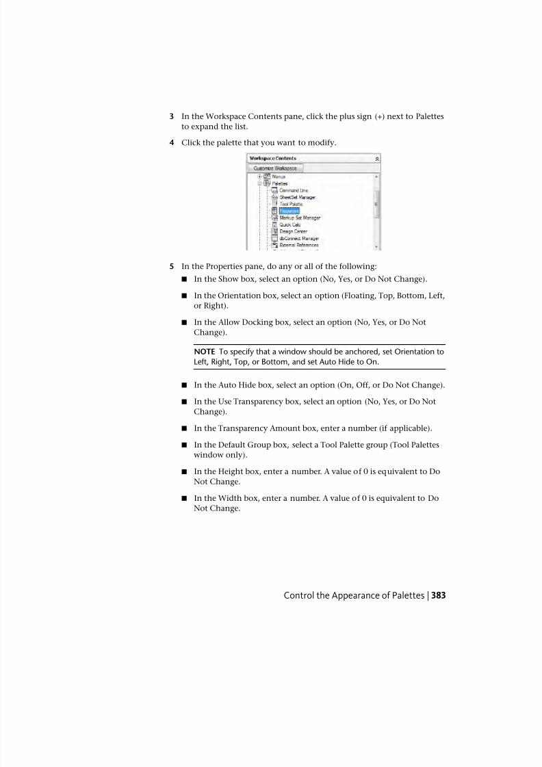
7/23/2019 Acad Customization
http://slidepdf.com/reader/full/acad-customization 391/553
3 In the Workspace Contents pane, click the plus sign (+) next to Palettes
to expand the list.
4 Click the palette that you want to modify.
5 In the Properties pane, do any or all of the following:■ In the Show box, select an option (No, Yes, or Do Not Change).
■ In the Orientation box, select an option (Floating, Top, Bottom, Left,
or Right).
■ In the Allow Docking box, select an option (No, Yes, or Do Not
Change).
NOTE To specify that a window should be anchored, set Orientation to
Left, Right, Top, or Bottom, and set Auto Hide to On.
■ In the Auto Hide box, select an option (On, Off, or Do Not Change).
■ In the Use Transparency box, select an option (No, Yes, or Do NotChange).
■ In the Transparency Amount box, enter a number (if applicable).
■ In the Default Group box, select a Tool Palette group (Tool Palettes
window only).
■ In the Height box, enter a number. A value of 0 is equivalent to Do
Not Change.
■ In the Width box, enter a number. A value of 0 is equivalent to Do
Not Change.
Control the Appearance of Palettes | 383

7/23/2019 Acad Customization
http://slidepdf.com/reader/full/acad-customization 392/553
6 Click Apply.
Quick Reference
Commands
CUIManages the customized user interface elements in the product.
Transfer and Migrate CustomizationYou can transfer and migrate data from a customization or menu file from an
earlier release using the Customize User Interface (CUI) Editor and the Migrate
Custom Settings dialog box.
Transfer Customization
The Customize User Interface (CUI) Editor can be used to transfer data in a
CUI, MNU, or MNS file to a CUIx file without modifying the original
customization or menu file. The new customization file that is created hasthe same name as the original file, but with a .cuix extension.
You can also transfer customization information between files. For example,
you can transfer toolbars from a partial CUIx file to the main CUIx file so that
the program can display the toolbar information. In addition, you can move
customizations from the main CUIx file to partial CUIx files, or from a partial
CUIx file to another partial CUIx file.
NOTE All elements can be transferred between two CUIx files with the exception
of the property settings defined under the Quick Properties and Rollover Tooltips
nodes.
If you transfer user interface elements that reference other user interface
elements, such as a flyout, all the relevant information for that interface
384 | Chapter 4 User Interface Customization
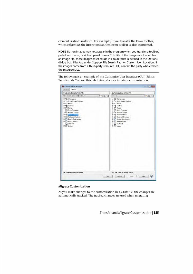
7/23/2019 Acad Customization
http://slidepdf.com/reader/full/acad-customization 393/553
element is also transferred. For example, if you transfer the Draw toolbar,
which references the Insert toolbar, the Insert toolbar is also transferred.
NOTE Button images may not appear in the program when you transfer a toolbar,
pull-down menu, or ribbon panel from a CUIx file. If the images are loaded from
an image file, those images must reside in a folder that is defined in the Options
dialog box, Files tab under Support File Search Path or Custom Icon Location. If
the images come from a third-party resource DLL, contact the party who created
the resource DLL.
The following is an example of the Customize User Interface (CUI) Editor,
Transfer tab. You use this tab to transfer user interface customization.
Migrate Customization
As you make changes to the customization in a CUIx file, the changes areautomatically tracked. The tracked changes are used when migrating
Transfer and Migrate Customization | 385
7/23/2019 Acad Customization
http://slidepdf.com/reader/full/acad-customization 394/553
customization from release to release with the Migrate Custom Settings dialog
box. In the Migrate Custom Settings dialog box, you can migrate any changes
made to the standard CUIx files that come with the program with the newshipping versions of the files with the same name. You can avoid manually
migrating customization, which might result in the loss of customization.
NOTE The Migrate Custom Settings dialog box can be used to migrate user
interface customization from previous releases. To access the Migrate Custom
Settings dialog box, click Start menu (Windows) ➤ All Programs (or Programs)
➤ Autodesk ➤ AutoCAD 2011 ➤ Migrate Custom Settings.
To transfer customizations
1 Click Manage tab ➤ Customization panel ➤ Import Customizations.
2 In the Customize User Interface Editor, Transfer tab, in the left pane,
click the Open Customization File button.
3 In the Open dialog box, locate the customization file (MNU, MNS, CUI,
or CUIx) from which you want to import customizations, and select it.
Click Open.
4 In the right pane, click the Open Customization File button.
5 In the Open dialog box, locate the customization file (MNU, MNS, CUI,
or CUIx) to which you want to export customizations, and select it. Click
Open.
6 In the left pane, click the plus sign (+) next to an interface element node
to expand it. Expand the corresponding node in the right pane.
7 Drag interface elements from the right pane to the appropriate location
in the left pane.
386 | Chapter 4 User Interface Customization
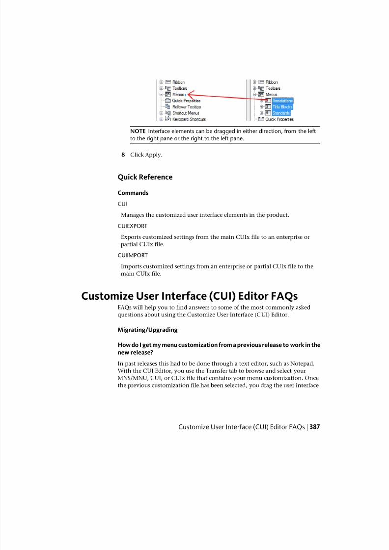
7/23/2019 Acad Customization
http://slidepdf.com/reader/full/acad-customization 395/553
NOTE Interface elements can be dragged in either direction, from the left
to the right pane or the right to the left pane.
8 Click Apply.
Quick Reference
Commands
CUI
Manages the customized user interface elements in the product.
CUIEXPORT
Exports customized settings from the main CUIx file to an enterprise or
partial CUIx file.
CUIIMPORT
Imports customized settings from an enterprise or partial CUIx file to the
main CUIx file.
Customize User Interface (CUI) Editor FAQsFAQs will help you to find answers to some of the most commonly asked
questions about using the Customize User Interface (CUI) Editor.
Migrating/Upgrading
How do I get my menu customization from a previous release to work in thenew release?
In past releases this had to be done through a text editor, such as Notepad.
With the CUI Editor, you use the Transfer tab to browse and select your
MNS/MNU, CUI, or CUIx file that contains your menu customization. Once
the previous customization file has been selected, you drag the user interface
Customize User Interface (CUI) Editor FAQs | 387
7/23/2019 Acad Customization
http://slidepdf.com/reader/full/acad-customization 396/553
elements between two CUIx files. See To transfer customizations on page 386
for more information.
Commands
How do I create a new command and add it to a user interface element, suchas a pull-down menu?
Commands are created and managed through the Command List pane located
in the lower-left corner of the Customize tab of the CUI Editor. See To create
a command on page 144 for more information.
Once the command has been created, it can be added to or used to create a
number of different user interface elements. To add the command to a menu
for example, expand the menu under the Menus node in the Customizations
In <file name> pane that you want to add the command to and then drag the
command under the menu. See To create a pull-down menu on page 272 formore information.
Menus
Why doesn’t my menu display on the menu bar?
Workspaces are used to control the display of menus on the menu bar. See To
display menus on the menu bar on page 377 for more information.
How do I change the order of a pull-down menu?
Workspaces are used to control the positioning of menus on the menu bar.
See To reposition menus on the menu bar on page 378 for more information.
Toolbars
Why do my toolbars not stay in the same place after I close and restartAutoCAD 2011?
This happens because of the way menus are loaded into AutoCAD at startup.
This problem only happens when partial and enterprise CUIx files are used.
To resolve this problem, you can use the new /w command line switch. This
causes AutoCAD 2011 to re-initialize the workspace upon startup and place
the toolbars in their correct locations. See To restore a workspace with a
command line switch on page 358 for more information.
388 | Chapter 4 User Interface Customization
7/23/2019 Acad Customization
http://slidepdf.com/reader/full/acad-customization 397/553
Why do my icons on a toolbar display as a cloud with a question mark afterI migrate them using the Transfer tab in the CUI Editor?
This happens because the images for the custom icons are not located in the
AutoCAD support file paths. Locate the images using Windows Explorer and
add the images location to the Support File Search Path node under the Files
tab of the Options dialog box, or copy them into the folder:
(Windows XP) <drive>:\Documents and Settings\<user profile name>\Application
Data\Autodesk\<product name>\<release number>\<language>\Support\Icons
(Windows Vista) <drive>:\Users\<user profile name>\AppData\Autodesk\<product
name>\<release number>\<language>\Support\Icons
Why does my toolbar flyout not work?
A flyout might not work for a few different reasons. There might not be any
commands currently assigned to the toolbar that it is referencing or a controlis part of the toolbar that is being referenced for the toolbar flyout. Launch
the CUI Editor and verify that there are commands on the toolbar that is being
referenced and if there are, make sure there are no controls on the toolbar
such as the Layer list control.
Why do I get an AutoCAD message box when I try to use a toolbar flyout?
The AutoCAD message box is displayed because the toolbar that is being
referenced for the toolbar flyout is not found. AutoCAD can’t find the toolbar
because it no longer exists, is not currently loaded because the partial CUIx
file it is in is not loaded, or the alias for the toolbar has been changed.
Launch the CUI Editor and select the flyout on the toolbar that currently is
not working properly. In the Properties pane look at the Source Toolbarproperty. Use the Find option to look for a toolbar element with an alias that
matches the text string in the Source Toolbar property of the flyout that does
not work. If one is not located, remove the flyout from the toolbar and drag
the toolbar that you want to reference as a flyout on the toolbar. Close the
CUI Editor. The flyout should now work correctly once again.
Double Click Actions
When I double-click an object nothing happens. Why is this happening?
There are a few different reasons why when double-clicking on an object in
the drawing nothing happens. The first and most common problem is with
the system variable PICKFIRST is set to 0. PICKFIRST must be set to a value of
1 in order for double-click editing to work. The next possible solution is that
Customize User Interface (CUI) Editor FAQs | 389
7/23/2019 Acad Customization
http://slidepdf.com/reader/full/acad-customization 398/553
double-click editing has been disabled. Double-click editing is controlled by
the system variable DBLCLKEDIT. If it is set to 0 it is currently turned off.
DBLCLKEDIT should be set to 1.
Workspaces
Why do my changes not appear after I click Apply?
This happens because the workspace that you made changes to is not the
current workspace. To resolve this problem, you need to set the workspace
current and then when changes are applied they will appear. See To set a
workspace current from the CUI Editor on page 357 for more information.
Enterprise CUIx Files
How do I edit an enterprise CUIx file if it is read-only in the CUI Editor?An enterprise CUIx file can only be edited when it is loaded as the main CUIx
file or as a partial CUIx file to the main CUIx file. It is recommended that you
load it as the main CUIx file when you need to make edits. If you are creating
a workspace that needs to include user interface elements from the CUIx file
that is normally designated as the main CUIx file, load the main CUIx file as
the enterprise CUIx file. Make edits to the enterprise CUIx file. See To modify
an enterprise CUIx file on page 133 for more information.
Quick Reference
Commands
CUI
Manages the customized user interface elements in the product.
CUIEXPORT
Exports customized settings from the main CUIx file to an enterprise or
partial CUIx file.
CUIIMPORT
Imports customized settings from an enterprise or partial CUIx file to the
main CUIx file.
CUILOAD
Loads a CUIx file.
390 | Chapter 4 User Interface Customization
7/23/2019 Acad Customization
http://slidepdf.com/reader/full/acad-customization 399/553
CUIUNLOAD
Unloads a CUIx file.OPTIONS
Customizes the program settings.
QUICKCUI
Displays the Customize User Interface Editor in a collapsed state.
WORKSPACE
Creates, modifies, and saves workspaces and makes a workspace current.
System Variables
ENTERPRISEMENU
Stores the enterprise customization file name (if defined), including the path
for the file name.
MENUNAME
Stores the customization file name, including the path for the file name.
WSCURRENT
Returns the current workspace name at the Command prompt and sets a
workspace to current.
Customize User Interface (CUI) Editor FAQs | 391

7/23/2019 Acad Customization
http://slidepdf.com/reader/full/acad-customization 400/553
392
7/23/2019 Acad Customization
http://slidepdf.com/reader/full/acad-customization 401/553
DIESEL
You can use DIESEL (Direct Interpretively Evaluated String Expression Language) to alter theAutoCAD® status line through the MODEMACRO system variable. You can also use DIESELin menu items as a macro language instead of AutoLISP®. DIESEL expressions accept stringsand generate string results.
Because DIESEL expressions handle strings exclusively, the USERS1-5 system variables areuseful for passing information from an AutoLISP routine to a DIESEL expression. DIESELexpressions are evaluated by AutoLISP routines through the use of the AutoLISP menucmd
function.
Customize the Status LineYou can use the MODEMACRO system variable to display information on the
status line.
Overview of the MODEMACRO System VariableThe status line can provide the user with important information without
interrupting the work flow. The MODEMACRO system variable controls the
user-defined area on the status line. The calculated value of the MODEMACRO
system variable is displayed in a left-aligned panel in the status bar at the bottom
of the AutoCAD®
window. This variable is set to the null string when you start
AutoCAD. Its value is not saved in the drawing, the configuration file, or
anywhere else.
The number of characters displayed on the status line is limited only by the size
of the AutoCAD window (and your monitor). The default panels move to the
right as the content of the MODEMACRO panel grows. It is possible to push
the default panels completely off the screen (if you want to).
5
393
7/23/2019 Acad Customization
http://slidepdf.com/reader/full/acad-customization 402/553
You can use the MODEMACRO system variable to display, in the status line,
most data known to AutoCAD. With its calculation, decision, and editing
facilities you can compose the status line to your precise specifications.
MODEMACRO is a user-string variable. It can be set to any string value. The
maximum string value is 4095 characters. You can set MODEMACRO with
SETVAR or by entering modemacro at the command prompt. If you modify
the MODEMACRO setting, you can experiment with various status line formats;
however, the maximum number of characters you can enter in this manner
is 255.
If you set MODEMACRO to the null string by entering a period (.), AutoCAD
displays the standard status line.
Quick Reference
Commands
SETVAR
Lists or changes the values of system variables.
System Variables
MODEMACRO
Displays a text string on the status line, such as the name of the current
drawing, time/date stamp, or special modes.
Set MODEMACRO ValuesYou can use text strings and DIESEL to display messages in the user-defined
section of the status line.
The value of MODEMACRO determines what is displayed in the mode status
line. The simplest (and least useful) MODEMACRO consists of constant text.
For example, to display a company name in the status line, you enter the
following:
Command: modemacro
New value for MODEMACRO, or . for none <"">: Greg's Bank and Grill
This MODEMACRO value always displays the same text; the status line does
not reflect changes to the AutoCAD internal state. It doesn't change until you
change MODEMACRO.
394 | Chapter 5 DIESEL
7/23/2019 Acad Customization
http://slidepdf.com/reader/full/acad-customization 403/553
7/23/2019 Acad Customization
http://slidepdf.com/reader/full/acad-customization 404/553
$(getvar,snapunit))),$(rtos,$(index,1,$(getvar,snapunit))) $(angtos,
$(getvar,snapang))
DIESEL copies its input directly to the output until it comes to the dollar sign
character ($) or a quoted string. You can use quoted strings to suppress
evaluation of character sequences that would otherwise be interpreted as
DIESEL functions. You can include quotation marks in quoted strings by using
two adjacent quotation marks. In the following example, the current layer is
set to LAYOUT, and MODEMACRO is set to the string.
Command: modemacro
New value for MODEMACRO, or . for none <"">: "$(getvar,clayer)=
"""$(getvar,clayer)""""
The status line displays the following:
$(getvar,clayer)="LAYOUT"
Quick Reference
Commands
SETVAR
Lists or changes the values of system variables.
System Variables
MODEMACRO
Displays a text string on the status line, such as the name of the current
drawing, time/date stamp, or special modes.
Set MODEMACRO with AutoLISPAnother way to set MODEMACRO values is to use AutoLISP.
You can save the code samples shown here as ASCII format text files and load
them with the AutoLISP load function.
The following AutoLISP command defines a MODEMACRO string that provides
similar information to that in the built-in status line. Because AutoLISP cannot
396 | Chapter 5 DIESEL
7/23/2019 Acad Customization
http://slidepdf.com/reader/full/acad-customization 405/553
continue strings from line to line, you use the AutoLISP strcat function to
assemble the complete MODEMACRO string from shorter component strings.
(defun C:ACADMODE ( )
(setvar "modemacro"
(strcat
"Layer $(substr,$(getvar,clayer),1,8)"
"$(if,$(getvar,orthomode), Ortho)"
"$(if,$(getvar,snapmode), Snap)"
"$(if,$(getvar,tabmode), Tablet)"
"$(if,$(=,$(getvar,tilemode),0),"
"$(if,$(=,$(getvar,cvport),1), P)"
")"
)
)
)
Save this AutoLISP routine in a file called acadmode.lsp. When you load the
routine and execute it, it displays information on the status line. This is not
the most useful application of this feature; it is provided only as an example.
The following sample acad.lsp file uses the S::STARTUP function to set the
MODEMACRO variable to a string defined by the AutoLISP file mode1.lsp.
;;; Sample acad.lsp file that uses S::STARTUP to load the
;;; file MODE1.LSP which defines a MODEMACRO string
(defun S::STARTUP ( )
(load "mode1")
(princ)
)
;;; Additional AutoLISP files can also be defined or;;; loaded here
When the AutoLISP file (mode1.lsp) is loaded, it uses the MODEMACRO system
variable to define a status line that displays L: followed by the first eight
characters of the layer name, the drawing name and a portion of the path,
and the first letter of each name of the currently active modes. The position
Set MODEMACRO with AutoLISP | 397
7/23/2019 Acad Customization
http://slidepdf.com/reader/full/acad-customization 406/553
of the drawing name remains constant, regardless of the length of the layer
name.
;;; MODE1.LSP
;;;
(setvar "modemacro"
(strcat
"L:$(substr,$(getvar,clayer),1,30)"
"$(substr, ,1,$(-,30,$(strlen,$(getvar,clayer)))) "
;; ^^^^^^^^ Note the 8 spaces here
"<.."
"$(if,$(eq,$(getvar,dwgname),UNNAMED),UNNAMED,"
"$(substr,$(getvar,dwgname),"
"$(if,$(>,$(strlen,$(getvar,dwgprefix)),29),"
"$(-,$(strlen,$(getvar,dwgprefix)),29),1"
"),"
"$(strlen,$(getvar,dwgname))"
")"
")"
">"
"$(if,$(getvar,orthomode), O, )"
"$(if,$(getvar,snapmode), S, )"
"$(if,$(getvar,tabmode), T, )"
"$(if,$(and,"
"$(=,$(getvar,tilemode),0),$(=,$(getvar,cvport),1)),P)"
)
)
Indenting code improves the readability of AutoLISP files and DIESEL strings.
Quick Reference
Commands
SETVAR
Lists or changes the values of system variables.
System Variables
MODEMACRO
Displays a text string on the status line, such as the name of the current
drawing, time/date stamp, or special modes.
398 | Chapter 5 DIESEL
7/23/2019 Acad Customization
http://slidepdf.com/reader/full/acad-customization 407/553
DIESEL Expressions in MacrosYou can use DIESEL string expressions in customization (CUI) files as anadditional method of creating macros.
These expressions can return string values (text strings) in response to standard
AutoCAD commands, AutoLISP and ObjectARX®
routines, and other macros.
They can also return string values to the menu itself, thereby altering the
appearance or content of a menu label.
This string provides a way to toggle between paper space and model space if
TILEMODE is set to 0. This expression is evaluated transparently. If the special
character P (which toggles MENUECHO on and off) is omitted, the expression
displays only the issued command.
A DIESEL expression that you use in a menu item must follow the
$section=submenu format where the section name is M and the submenu is
the DIESEL expression you want. Frequently, you can implement a macro
more easily with AutoLISP.
The following examples show two menu items that produce the same result;
one uses DIESEL, and the other uses AutoLISP.
This menu item uses the DIESEL expression:
^C^C^P$M=$(if,$(=,$(getvar,cvport),1),mspace,pspace)
This menu item uses the AutoLISP expression:
^C^C^P(if (= (getvar "cvport") 1)(command "mspace")+
(command "pspace"))(princ) ^P
Both menu items provide a way to switch between paper space and model
space (if TILEMODE is set to 0), but the DIESEL expression is shorter and isevaluated transparently, not requiring the call to the AutoLISP princ function.
If the special character ^P (which switches MENUECHO on and off) is omitted
in both cases, the DIESEL expression displays only the issued command,
whereas the AutoLISP expression displays the entire line of code.
Because the value returned by a DIESEL expression is a text string, it can be
used in response to an AutoLISP getxxx function call. This functionality
enables menu items to evaluate current drawing conditions and to return a
value to an AutoLISP routine.
The next example is based on these assumptions:
■ The AutoLISP routine is loaded into memory.
■ The CUI excerpt is included in the current customization file.
DIESEL Expressions in Macros | 399
7/23/2019 Acad Customization
http://slidepdf.com/reader/full/acad-customization 408/553
■ The symbols to insert are one unit high by one unit wide.
■ The DIMSCALE variable is set to the drawing's scale factor (that is, a drawingto be plotted at a scale of 1" = 10' would have a scale factor of 120, or a
1/4" = 1' scale drawing would have a scale factor of 48).
If you load and execute the sample AutoLISP routine, AutoCAD inserts the
symbol at the size and location you have specified. When plotted, the symbols
are the specified size (if the drawing is plotted at the same scale as that specified
by DIMSCALE).
The following is a sample AutoLISP routine.
(defun C:SYMIN ( )
(setq sym
(getstring
"\nEnter symbol name: ") ; Prompts for a symbol name)
(menucmd "s=symsize") ; Switches the screen menu
; to the symsize submenu
(setq
siz (getreal
"\nSelect symbol size: ") ; Prompts for a symbol size
p1 (getpoint
"\nInsertion point: ") ; Prompts for insertion point
)
(command "insert" ; Issues the INSERT command
sym ; using the desired symbol
p1 siz siz 0) ; insertion point, and size
(menucmd "s=") ; Switches to the previous
; screen menu
(princ) ; Exits quietly
)
NOTE An AutoLISP routine that you use regularly should include error checking
to verify the validity of user input.
The DIESEL expressions in the following example multiply the current value
of DIMSCALE by the specified value, and return an appropriate scale factor.
400 | Chapter 5 DIESEL
7/23/2019 Acad Customization
http://slidepdf.com/reader/full/acad-customization 409/553
This cannot be done with similar AutoLISP code; a value returned by an
AutoLISP expression cannot typically be used as a response to a getxxx function
call (such as, the getreal function in the preceding sample).
$M=$(*,$(getvar,dimscale),0.375)
$M=$(*,$(getvar,dimscale),0.5)
$M=$(*,$(getvar,dimscale),0.625)
DIESEL expressions can also return string values to pull-down menu item
labels, so that you can make menus unavailable or otherwise alter the way
they are displayed. To use a DIESEL expression in a pull-down menu label,
make sure that the first character is the $ character.
In the next example, the current layer is set to BASE and the following DIESEL
expression is used as the label.
$(eval,"Current layer: " $(getvar,clayer))
The result is that the appropriate pull-down menu is displayed and updated
whenever the current layer changes.
Current Layer: BASE
You can also use this method to interactively change the text displayed in a
pull-down menu. You use an AutoLISP routine that sets the USERS1-5 system
variables to the selected text, which can be retrieved by a DIESEL macro in a
menu label.
NOTE The width of pull-down and shortcut menus is determined when the
customization file is being loaded. Menu labels generated or changed by DIESEL
expressions after a menu is loaded are truncated to fit within the existing menu
width.
If you anticipate that a DIESEL-generated menu label will be too wide, you
can use the following example to ensure that the menu width will
accommodate your labels. This example displays the first 10 characters of the
current value of the USERS3 (USERS1-5) system variable.
$(eval,"Current value: " $(getvar,users3))+
$(if, $(eq,$(getvar,users3),""), 10 spaces )^C^Cusers3
You cannot use trailing spaces in a menu label to increase the menu width,
because trailing spaces are ignored while the menu is being loaded. Any spaces
you use to increase the width of a menu label must be within a DIESEL
expression.
DIESEL Expressions in Macros | 401
7/23/2019 Acad Customization
http://slidepdf.com/reader/full/acad-customization 410/553
The next example uses the same DIESEL expression as the label and a portion
of the menu item. It provides a practical way to enter the current day and
date into a drawing.
$(edtime,$(getvar,date),DDD", "D MON YYYY)^C^Ctext +
\\\ $M=$(edtime,$(getvar,date),DDD", "D MON YYYY);
Also, you can use a DIESEL macro to mark pull-down menu labels or make
them unavailable. The following pull-down menu label displays an unavailable
ERASE while a command is active. The text is displayed normally when a
command is not active.
$(if,$(getvar,cmdactive),~)ERASE
You can use a similar approach to place a mark beside a pull-down menu item
or to interactively change the character used for the mark.
Quick Reference
System Variables
MENUECHO
Sets menu echo and prompt control bits.
USERS1-5
Provides storage and retrieval of text string data.
Catalog of DIESEL FunctionsStatus retrieval, computation, and display are performed by DIESEL functions.All functions have a limit of 10 parameters, including the function name itself.
If this limit is exceeded, you get a DIESEL error message.
+ (addition)
Returns the sum of the numbers val1, val2, …, val9.
$(+, val1 [, val2, …, val9])
If the current thickness is set to 5, the following DIESEL string returns 15.
$(+, $(getvar,thickness),10)
402 | Chapter 5 DIESEL
7/23/2019 Acad Customization
http://slidepdf.com/reader/full/acad-customization 411/553
Quick Reference
System Variables
MENUECHO
Sets menu echo and prompt control bits.
- (subtraction)
Returns the result of subtracting the numbers val2 through val9 from val1.
$(-, val1 [, val2 , …, val9])
Quick Reference
System Variables
MENUECHO
Sets menu echo and prompt control bits.
* (multiplication)
Returns the result of multiplying the numbers val1, val2, …, val9.
$(*, val1 [, val2, …, val9])
Quick Reference
System Variables
MENUECHO
Sets menu echo and prompt control bits.
/ (division)
Returns the result of dividing the number val1 by val2, …, val9.
$(/, val1 [, val2, …, val9])
- (subtraction) | 403
7/23/2019 Acad Customization
http://slidepdf.com/reader/full/acad-customization 412/553
Quick Reference
System Variables
MENUECHO
Sets menu echo and prompt control bits.
= (equal to)
If the numbers val1 and val2 are equal, the string returns 1; otherwise, it
returns 0.
$(=, val1, val2)
Quick Reference
System Variables
MENUECHO
Sets menu echo and prompt control bits.
< (less than)
If the number val1 is less than val2, the string returns 1; otherwise, it returns
0.
$(< , val1, val2)
The following expression gets the current value of HPANG; if the value is less
than the value stored in the system variable USERR1, it returns 1. If the value
10.0 is stored in USERR1 and the current setting of HPANG is 15.5, the
following string returns 0.
$(<, $(getvar,hpang),$(getvar,userr1))
Quick Reference
System Variables
MENUECHO
Sets menu echo and prompt control bits.
404 | Chapter 5 DIESEL
7/23/2019 Acad Customization
http://slidepdf.com/reader/full/acad-customization 413/553
> (greater than)
If the number val1 is greater than val2, the string returns 1; otherwise, it
returns 0.
$(>, val1, val2)
Quick Reference
System Variables
MENUECHO
Sets menu echo and prompt control bits.
!= (not equal to)
If the numbers val1 and val2 are not equal, the string returns 1; otherwise,
it returns 0.
$(!=, val1, val2)
Quick Reference
System Variables
MENUECHO
Sets menu echo and prompt control bits.
<= (less than or equal to)
If the number val1 is less than or equal to val2 , the string returns 1; otherwise,
it returns 0.
$(<=, val1, val2)
> (greater than) | 405
7/23/2019 Acad Customization
http://slidepdf.com/reader/full/acad-customization 414/553
Quick Reference
System Variables
MENUECHO
Sets menu echo and prompt control bits.
>= (greater than or equal to)
If the number val1 is greater than or equal to val2, the string returns 1;
otherwise, it returns 0.
$(>=, val1, val2)
Quick Reference
System Variables
MENUECHO
Sets menu echo and prompt control bits.
and
Returns the bitwise logical AND of the integers val1 through val9.
$(and, val1 [, val2,…, val9])
Quick Reference
System Variables
MENUECHO
Sets menu echo and prompt control bits.
angtos
Returns the angular value in the format and precision specified.
$(angtos, value [, mode, precision])
406 | Chapter 5 DIESEL
7/23/2019 Acad Customization
http://slidepdf.com/reader/full/acad-customization 415/553
Edits the given value as an angle in the format specified by the mode and
precision as defined for the analogous AutoLISPfunction. (The values for
mode are shown in the following table.) If mode and precision are omitted, ituses the current values chosen by the UNITS command.
Angular units values
String formatMode value
Degrees0
De-
grees/minutes/seconds
1
Grads2
Radians3
Surveyor's units4
Quick Reference
System Variables
MENUECHO
Sets menu echo and prompt control bits.
edtimeReturns a formatted date and time based on a given picture.
$(edtime, time, picture)
Edits the AutoCAD Julian date given by time (obtained, for example, from
$(getvar,date) according to the given picture). The picture consists of
format phrases replaced by specific representations of the date and time.
Characters not interpretable as format phrases are copied literally into the
result of $(edtime). Format phrases are defined as shown in the following
edtime | 407
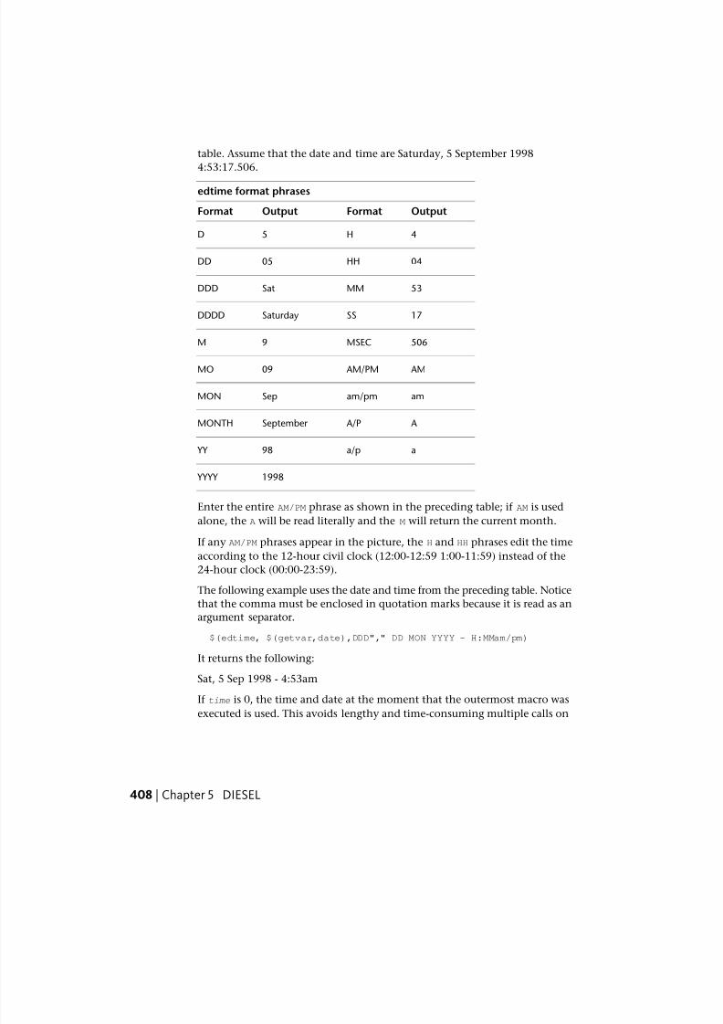
7/23/2019 Acad Customization
http://slidepdf.com/reader/full/acad-customization 416/553
table. Assume that the date and time are Saturday, 5 September 1998
4:53:17.506.
edtime format phrases
OutputFormatOutputFormat
4H5D
04HH05DD
53MMSatDDD
17SSSaturdayDDDD
506MSEC9M
AM AM/PM09MO
amam/pmSepMON
A A/PSeptember MONTH
aa/p98 YY
1998 YYYY
Enter the entire AM/PM phrase as shown in the preceding table; if AM is used
alone, the A will be read literally and the M will return the current month.
If any AM/PM phrases appear in the picture, the H and HH phrases edit the time
according to the 12-hour civil clock (12:00-12:59 1:00-11:59) instead of the
24-hour clock (00:00-23:59).
The following example uses the date and time from the preceding table. Notice
that the comma must be enclosed in quotation marks because it is read as an
argument separator.
$(edtime, $(getvar,date),DDD"," DD MON YYYY - H:MMam/pm)
It returns the following:
Sat, 5 Sep 1998 - 4:53am
If time is 0, the time and date at the moment that the outermost macro was
executed is used. This avoids lengthy and time-consuming multiple calls on
408 | Chapter 5 DIESEL
7/23/2019 Acad Customization
http://slidepdf.com/reader/full/acad-customization 417/553
$(getvar,date) and guarantees that strings composed with multiple $(edtime)
macros all use the same time.
Quick Reference
System Variables
MENUECHO
Sets menu echo and prompt control bits.
eq
If the strings val1 and val2 are identical, the string returns 1; otherwise, it
returns 0.
$(eq, val1, val2)
The following expression gets the name of the current layer; if the name
matches the string value stored in the USERS1 (USERS1-5) system variable, it
returns 1. Assume the string "PART12" is stored in USERS1 and the current
layer is the same.
$(eq, $(getvar,users1),$(getvar,clayer))Returns 1
Quick Reference
System Variables
MENUECHO
Sets menu echo and prompt control bits.
eval
Passes the string str to the DIESEL evaluator and returns the result of
evaluating it.
$(eval, str)
eq | 409
7/23/2019 Acad Customization
http://slidepdf.com/reader/full/acad-customization 418/553
Quick Reference
System Variables
MENUECHO
Sets menu echo and prompt control bits.
fix
Truncates the real number value to an integer by discarding any fractional
part.
$(fix, value)
Quick Reference
System Variables
MENUECHO
Sets menu echo and prompt control bits.
getenv
Returns the value of the environment variable varname.
$(getenv, varname)
If no variable with that name is defined, it returns the null string.
Quick Reference
System Variables
MENUECHO
Sets menu echo and prompt control bits.
410 | Chapter 5 DIESEL
7/23/2019 Acad Customization
http://slidepdf.com/reader/full/acad-customization 419/553
getvar
Returns the value of the system variable with the given varname.
$(getvar, varname)
Quick Reference
System Variables
MENUECHO
Sets menu echo and prompt control bits.
if Conditionally evaluates expressions.
$(if, expr, dotrue [, dofalse])
If expr is nonzero, it evaluates and returns dotrue. Otherwise, it evaluates
and returns dofalse. Note that the branch not chosen by expr is not evaluated.
Quick Reference
System Variables
MENUECHO
Sets menu echo and prompt control bits.
index
Returns the specified member of a comma-delimited string.
$(index, which, string)
Assumes that the string argument contains one or more values delimited by
the macro argument separator character, the comma. The which argument
selects one of these values to be extracted, with the first item numbered 0.
This function is most frequently used to extract X , Y , or Z coordinate values
from point coordinates returned by $(getvar).
getvar | 411
7/23/2019 Acad Customization
http://slidepdf.com/reader/full/acad-customization 420/553
Applications can use this function to retrieve values stored as comma-delimited
strings from the USERS1-5 system variables.
Quick Reference
System Variables
MENUECHO
Sets menu echo and prompt control bits.
nth
Evaluates and returns the argument selected by which.
$(nth, which, arg0 [, arg1,…, arg7])
If which is 0, nth returns arg0, and so on. Note the difference between $(nth)
and $(index); $(nth)returns one of a series of arguments to the function,
while $(index) extracts a value from a comma-delimited string passed as a
single argument. Arguments not selected by which are not evaluated.
Quick Reference
System Variables
MENUECHO
Sets menu echo and prompt control bits.
or
Returns the bitwise logical OR of the integers val1 through val9.
$(or, val1 [, val2,…, val9])
Quick Reference
System Variables
MENUECHO
Sets menu echo and prompt control bits.
412 | Chapter 5 DIESEL
7/23/2019 Acad Customization
http://slidepdf.com/reader/full/acad-customization 421/553
rtos
Returns the real value in the format and precision specified.
$(rtos, value [, mode, precision])
Edits the given value as a real number in the format specified by the mode and
precision as defined by the analogous AutoLISP function. If mode and
precision are omitted, it uses the current values selected with the UNITS
command.
Edits the given value as a real number in the format specified by mode and
precision. If mode and precision are omitted, it uses the current values
selected with the UNITS command.
Quick ReferenceSystem Variables
MENUECHO
Sets menu echo and prompt control bits.
strlen
Returns the length of string in characters.
$(strlen, string)
Quick Reference
System Variables
MENUECHO
Sets menu echo and prompt control bits.
substr
Returns the substring of string , starting at character start and extending for
length characters.
$(substr, string, start [, length])
rtos | 413
7/23/2019 Acad Customization
http://slidepdf.com/reader/full/acad-customization 422/553
7/23/2019 Acad Customization
http://slidepdf.com/reader/full/acad-customization 423/553
DIESEL Error MessagesGenerally, if you make a mistake in a DIESEL expression, what went wrongwill be obvious. Depending on the nature of the error, DIESEL embeds an
error indication in the output stream.
DIESEL error messages
DescriptionError message
Syntax error (usually a missing right parenthesis or a runaway
string)
$?
Incorrect arguments to func $(func,??)
Unknown function func $(func)??
Output string too long—evaluation truncated$(++)
Quick Reference
System Variables
MENUECHO
Sets menu echo and prompt control bits.
DIESEL Error Messages | 415

7/23/2019 Acad Customization
http://slidepdf.com/reader/full/acad-customization 424/553
416
7/23/2019 Acad Customization
http://slidepdf.com/reader/full/acad-customization 425/553
Slides and CommandScripts
Slides are snapshots of drawing files that can be used for giving presentations, for creatingimage tile menus, and for viewing another drawing while you work.
A script reads and executes commands from a text file. You can run a script when you startAutoCAD®, or you can run a script from within AutoCAD using the SCRIPT command. Ascript provides an easy way to create continuously running displays for product demonstrationsand trade shows.
Create SlidesSlides are snapshots of drawing files. You can use slides for giving presentations,
creating custom image tile menus, and viewing an image of another drawing
while you work.
Overview of SlidesA slide is a snapshot of a drawing. Although it contains a picture of the drawing
at a given instant, it is not a drawing file.
You cannot import a slide file into the current drawing, nor can you edit or
print a slide. You can only view it.
You can use slide files in the following ways:
■ For making presentations within AutoCAD®
■ For viewing a snapshot of a drawing while working on a different drawing
■
For creating menus of image tiles within a dialog box
6
417
7/23/2019 Acad Customization
http://slidepdf.com/reader/full/acad-customization 426/553
You create a slide by saving the current view in slide format. A slide created
in model space shows only the current viewport. A slide created in paper space
shows all visible viewports and their contents. Slides show only what wasvisible. They do not show objects on layers that were turned off or frozen or
objects in viewports that were turned off.
When you view a slide file, it temporarily replaces objects on the screen. You
can draw on top of it, but when you change the view (by redrawing, panning,
or zooming), the slide file disappears, and AutoCAD redisplays only what you
drew and any preexisting objects.
You can display slides one by one or use a script to display slides in sequence.
Slides also can be used in custom menus. For example, if you create scripts
that insert blocks containing mechanical parts you use frequently, you can
design a custom image tile menu that displays a slide of each part. When you
click the slide image on the menu, AutoCAD inserts the block into the drawing.
A slide library is a file containing one or more slides. Slide library files are used
for creating custom image tile menus and for combining several slide files for
convenient file management.
You cannot edit a slide. You must change the original drawing and remake
the slide. If you use a low-resolution graphics monitor when creating a slide
file and later upgrade to a high-resolution monitor, you can still view the
slide. AutoCAD adjusts the image accordingly; however, the slide does not
take full advantage of the new monitor until you remake the slide file from
the original drawing.
To make a slide
1 Display the view you want to use for the slide.
2 At the command prompt, enter mslide.
3 In the Create Slide File dialog box, enter a name and select a location for
the slide.
AutoCAD offers the current name of the drawing as a default name for
the slide and automatically appends the .sld file extension.
4 Click Save.
The current drawing remains on the screen, and the slide file is saved in
the folder that you specified.
418 | Chapter 6 Slides and Command Scripts
7/23/2019 Acad Customization
http://slidepdf.com/reader/full/acad-customization 427/553
Quick Reference
Commands
MSLIDE
Creates a slide file of the current model viewport or the current layout.
REDRAW
Refreshes the display in the current viewport.
VSLIDE
Displays an image slide file in the current viewport.
System Variables
FILEDIA
Suppresses display of file navigation dialog boxes.
Utilities
SLIDELIB
Compiles slide files listed in an ASCII file into a slide library file.
View SlidesYou can view slides individually using VSLIDE. To view a series of slides for a
presentation, use a script file.
Be careful about using editing commands while you view a slide, which looks
like an ordinary drawing. Editing commands affect the current drawing
underneath the slide but not the slide itself.
Some commands may force redrawing, which removes the slide from display.
To view a slide
1 At the command prompt, enter vslide.
2 In the Select Slide File dialog box, select a slide to view and click OK.
The slide image is displayed in the drawing area.
3 Click View menu ➤ Redraw.
The slide image disappears.
View Slides | 419
7/23/2019 Acad Customization
http://slidepdf.com/reader/full/acad-customization 428/553
Quick Reference
Commands
REDRAW
Refreshes the display in the current viewport.
VSLIDE
Displays an image slide file in the current viewport.
Create and View Slide LibrariesA slide library is a file containing one or more slides. Slide library files are used
for creating custom image tile menus and for combining several slide files for
convenient file management.
You can create slide libraries from slide files using the SLIDELIB utility. After
you have set up a slide library, you can view slides by specifying the name of
the slide library and the slide.
Do not delete the original slides after creating the slide library. The SLIDELIB
utility cannot update a slide library once it is created. If you want to add or
delete a slide, update the slide list file and remake the library with SLIDELIB.
When you remake the slide library, all the slide files that you intend to include
must be available.
To create a slide library
1 Use a Windows ASCII text editor to create a list of slide files to include
in the library. The file would look similar to this example:
entrance.sld
hall.sld
stairs.sld
study.sld
balcony.sld
2 Name and save the file as a text file with a .txt file extension.
3 Click Start menu (Windows) ➤ All Programs (or Programs) ➤ Accessories
➤ Command Prompt.
4 In the Command Prompt window, at the prompt, enter CD <folderlocation of slides> to change folders.
420 | Chapter 6 Slides and Command Scripts
7/23/2019 Acad Customization
http://slidepdf.com/reader/full/acad-customization 429/553
As an example: CD “c:\slides”
5 At the prompt, enter the following syntax to create the slide library:slidelib libraryname < list.txt
For example, if you named your text file areas .txt , you could create a
library called house .slb by entering slidelib house < areas.txt. The SLIDELIB
utility appends the file extension .slb to the slide library file.
To view a slide in a slide library
1 At the command prompt, enter filedia.
2 Enter 0 and press ENTER.
3 At the command prompt, enter vslide.
4 Enter library(slidename) to specify the slide.For example, enter house (balcony) to open the balcony slide, which is
stored in the house slide library file.
5 To remove the slide from the display, click View menu ➤ Redraw.
Quick Reference
Commands
MSLIDE
Creates a slide file of the current model viewport or the current layout.
REDRAW
Refreshes the display in the current viewport.
VSLIDE
Displays an image slide file in the current viewport.
Utilities
SLIDELIB
Compiles slide files listed in an ASCII file into a slide library file.
Create and View Slide Libraries | 421
7/23/2019 Acad Customization
http://slidepdf.com/reader/full/acad-customization 430/553
Create Command ScriptsA script is a text file that contains a series of commands. Common uses forscripts are to customize startup and to run slide shows.
Overview of Command Scripts
A script is a text file with one command on each line.
You can invoke a script at startup, or you can run a script during a work session
by using the SCRIPT command. A script also provides an easy way to create
continuously running displays for product demonstrations and trade shows.
The BACKGROUNDPLOT system variable must be set to 0 before a script can
plot multiple jobs.
You create script files outside the program using a text editor (such asMicrosoft® Windows® Notepad) or a word processor (such as Microsoft Word)
that can save the file in ASCII format. The file extension must be .scr .
Each line of the script file contains a command. Each blank space in a script
file is significant because SPACEBAR is accepted as a command or data field
terminator. You must be very familiar with the sequence of prompts to provide
an appropriate sequence of responses in the script file.
NOTE Keep in mind that prompts and command names may change in future
releases, so you may need to revise your scripts when you upgrade to a later version
of this program. For similar reasons, avoid the use of abbreviations; future command
additions might create ambiguities.
A script can execute any command at the command prompt except a command
that displays a dialog box. In most cases, a command that displays a dialog
box has an alternative version of the command that displays command
prompts instead of a dialog box.
Script files can contain comments. Any line that begins with a semicolon (;)
is considered a comment, and it is ignored while the script file is being
processed. The last line of the file must be blank.
All references to long file names that contain embedded spaces must be
enclosed in double quotes. For example, to open the drawing my house.dwg
from a script, you must use the following syntax:
open "my house"
The following commands are useful in scripts:
422 | Chapter 6 Slides and Command Scripts
7/23/2019 Acad Customization
http://slidepdf.com/reader/full/acad-customization 431/553
'DELAY Provides a timed pause within a script (in milliseconds)
'GRAPHSCR Switches from the text window to the drawing area
RESUME Continues an interrupted script
RSCRIPT Repeats a script file
'TEXTSCR Switches to the text window
When command input comes from a script, it is assumed that the settings of
the PICKADD and PICKAUTO system variables are 1 and 0, respectively;
therefore, you do not have to check the settings of these variables.
A script is treated as a group, a unit of commands, reversible by a single U
command. However, each command in the script causes an entry in the undo
log, which can slow script processing. If you like, you can use UNDO Control
None to turn off the undo feature before running the script, or you can write
it at the beginning of the script itself. Remember to turn it back on (UNDO
Control All) when the script is finished.
The script that is running stops when another script command is invoked.
To create a script that changes settings in a drawing
This script turns on the grid, sets the global linetype scale to 3.0, and sets layer
0 as the current layer with red as the color.
1 In a text editor, enter grid on.
2 On the next line, enter ltscale 3.0.
3 On the next line, enter layer set 0 color red 0.
4 Add a blank line.
5 Save the file as ASCII text (TXT file), with a file extension of .scr .
The script file may contain comments, as follows:
; Turn grid on
grid on
; Set scale for linetypes
ltscale 3.0
; Set current layer and its color
layer set 0 color red 0
; Blank line above to end LAYER command
Overview of Command Scripts | 423
7/23/2019 Acad Customization
http://slidepdf.com/reader/full/acad-customization 432/553
7/23/2019 Acad Customization
http://slidepdf.com/reader/full/acad-customization 433/553
NOTE VBA and AutoLISP®
scripts that run at startup should check for whether the
AutoCAD process is visible or invisible. If the process is invisible, the script should
not execute, because the process may be performing background plotting or
publishing operations. To check for whether the AutoCAD process is visible or
invisible, you can use the Visible property of the Application object in the AutoCAD
Object Model.
You could run a script at startup to open a drawing by using the following
syntax in the Run dialog box:
ACAD drawing_name /b setup
All file names that contain embedded spaces must be enclosed in double
quotes, for example, “guest house”. You can also specify the view that is
displayed when the drawing opens by using the /v switch and the view name.
The /b switch and the script file must be the last parameter listed.
Including the file extensions .exe , .dwg , .dwt , and .scr is optional. If AutoCAD
cannot find the script file, AutoCAD reports that it cannot open the file.
To run the same script at startup but create a new drawing using the
MyTemplate.dwt file as the template, enter the following in the Run dialog box:
ACAD /t MyTemplate /b setup
This command creates a new drawing and issues a sequence of setup commands
from the setup.scr file. When the script has finished running, the command
prompt is displayed. If you want to use the default template for the new
drawing, you can omit the /t switch and the template file name.
NOTE You can no longer use this method to start a new drawing and give it a
name. Name the drawing when you save it.
To run a script at startup
1 Click Start menu (Windows) ➤ Run.
2 In the Run dialog box, enter acad drawing_name /b script_name.
To start a new file, instead of a drawing file name, enter the /t switch and
the name of a template file: /t template_drawing.
To open a drawing file to a particular view, follow the drawing name
with the /v switch and the name of the view: /v view_name.
The name of the script file must be the last parameter listed. The file
extensions are optional.
3 Click OK.
Run Scripts at Startup | 425
7/23/2019 Acad Customization
http://slidepdf.com/reader/full/acad-customization 434/553
AutoCAD opens the drawing and executes the commands in the script
file. When the script has been completed, the command prompt is
displayed.
Run Slide Shows from ScriptsScripts are useful for creating slide shows.
Scripts are useful for creating slide shows. Ordinarily, the speed with which
you can display slides is limited by the number of times AutoCAD must access
the disk to read the slide file. You can, however, preload the next slide from
disk into memory while your audience is viewing the current slide and then
quickly display the new slide from memory.
To preload a slide, place an asterisk before the file name in VSLIDE. The next
VSLIDE command detects that a slide has been preloaded and displays itwithout asking for a file name.
The disk-access time to load the next slide overlaps with the viewing time for
the current slide. You can specify additional delays with the DELAY command.
Each delay unit is equal to one millisecond.
To stop a repeating script press ESC. You can resume the script with RESUME.
If the script will run for a long time, it is recommended that you use UNDO
Control None to turn off the Undo log file.
To run slide shows from scripts
1 Create the slide library file as described in To create a slide library on page
420.
2 Create a script file using an ASCII text editor, as shown in To create a
script that preloads slides on page 426.
3 At the command prompt, enter script.
4 In the Select Script File dialog box, select a script file and click Open.
To create a script that preloads slides
In this example of a script that displays three slides (files slide1.sld , slide2.sld,and slide3.sld ), the time it takes to access the disk drive and load the next slide
into memory overlaps with the viewing time for the current slide.
1 On the first line of the script, enter vslide slide1.
426 | Chapter 6 Slides and Command Scripts
7/23/2019 Acad Customization
http://slidepdf.com/reader/full/acad-customization 435/553
The first line begins the slide show and loads slide1.
2 On the second line, enter vslide *slide2.The asterisk (*) preceding the slide name on the second line preloads
slide2.
3 On the third line, enter delay 2000.
The third line specifies a delay of 2000 milliseconds to allow the audience
to view slide1.
4 On the fourth line, enter vslide. On the fifth line, enter vslide *slide3.
On the sixth line, enter delay 2000.
The fourth, fifth, and sixth lines display slide2, preload slide3, and specify
a delay for viewing slide2.
5 On the seventh line, enter vslide. On the eighth line, enter delay 3000.
The seventh and eighth lines display slide3 and specify a delay for viewing
slide3.
6 On the last line, enter rscript to repeat the script.
7 To stop a repeating script press ESC. To continue the script, enter resume.
The script may contain comments, as follows:
; Begin slide show, load SLIDE1
VSLIDE SLIDE1
; Preload SLIDE2
VSLIDE *SLIDE2
; Let audience view SLIDE1
DELAY 2000; Display SLIDE2
VSLIDE
; Preload SLIDE3
VSLIDE *SLIDE3
; Let audience view SLIDE2
DELAY 2000
; Display SLIDE3
VSLIDE
; Let audience view SLIDE3
DELAY 3000
; Cycle
RSCRIPT
Run Slide Shows from Scripts | 427
7/23/2019 Acad Customization
http://slidepdf.com/reader/full/acad-customization 436/553
Quick Reference
Commands
DELAY
Provides a timed pause within a script.
GRAPHSCR
Switches from the text window to the drawing area.
RESUME
Continues an interrupted script.
RSCRIPT
Repeats a script file.
SCRIPT
Executes a sequence of commands from a script file.
TEXTSCR
Opens the text window.
VSLIDE
Displays an image slide file in the current viewport.
428 | Chapter 6 Slides and Command Scripts
7/23/2019 Acad Customization
http://slidepdf.com/reader/full/acad-customization 437/553
Introduction toProgramming Interfaces
The programming interfaces introduced here are ActiveX® Automation, VBA (Visual Basic®
for Applications), AutoLISP®, Visual LISP™ , ObjectARX™ , and .NET. The type of interface
you use depends on your application needs and programming experience.
ActiveX AutomationActiveX Automation is a technology developed by Microsoft
®and is based on
the COM (component object model) architecture. You can use it to customize
AutoCAD, share your drawing data with other applications, and automate tasks.
Overview of ActiveX
You can create and manipulate AutoCAD objects from any application thatserves as an Automation controller. Thus, Automation enables macro
programming across applications, a capability that does not exist in AutoLISP.
Through Automation, AutoCAD exposes programmable objects, described by
the AutoCAD Object Model, that can be created, edited, and manipulated by
other applications. Any application that can access the AutoCAD Object Model
is an Automation controller, and the most common tool used for manipulating
another application using Automation is Visual Basic for Applications (VBA).
VBA is found as a component in many Microsoft Office applications. You can
use these applications, or other Automation controllers, such as Visual Basic,
.NET, and Delphi, to drive AutoCAD.
7
429

7/23/2019 Acad Customization
http://slidepdf.com/reader/full/acad-customization 438/553
The advantage of implementing an ActiveX interface for AutoCAD is twofold:
■ Programmatic access to AutoCAD drawings is opened up to many moreprogramming environments. Before ActiveX Automation, developers were
limited to an AutoLISP or C++ interface.
■ Sharing data with other Windows applications, such as Microsoft Excel
and Microsoft Word, is made dramatically easier.
For detailed information about using VBA to control AutoCAD ActiveX
Automation, see the ActiveX and VBA Developer's Guide and ActiveX and VBA
Reference in the Help system. To display Developer Help, on the InfoCenter
toolbar, to the right of the Help button, click the drop-down arrow. From the
menu, click Additional Resources ➤ Developer Help.
For example, you might want to prompt for input, set preferences, make a
selection set, or retrieve drawing data. You can decide on the controller touse, depending on the type of manipulation.
Using Automation, you can create and manipulate AutoCAD objects from any
application that serves as an Automation controller. Thus, Automation enables
macro programming across applications, a capability that does not exist in
AutoLISP. With Automation you can combine the features of many applications
into a single application.
The displayed objects are called Automation objects . Automation objects make
methods, properties, and events available. Methods are functions that perform
an action on an object. Properties are functions that set or return information
about the state of an object. Events are user-initiated actions or occurrences to
which a program responds.
Virtually any type of application can access the displayed Automation objectswithin AutoCAD. These applications can be stand-alone executables, dynamic
linked library (DLL) files, and macros within applications such as Microsoft
Word or Microsoft Excel. The most common of these is most likely the
stand-alone executable. If you are using applications from application
developers, follow their instructions for installation and use of their product.
See also:
■ ActiveX Automation and VBA
430 | Chapter 7 Introduction to Programming Interfaces
7/23/2019 Acad Customization
http://slidepdf.com/reader/full/acad-customization 439/553
Define a Command to Start Your ApplicationYou can use the acad.pgp file to define a new AutoCAD command that runsan external command to start your application.
You can use the acad.pgp file to define a new AutoCAD command that runs
an external command to start your application. The following example defines
the RUNAPP1 command, which runs the application app1.exe in the c:\vbapps\
directory. (Add this code to the external commands section of your acad.pgp
file.)
RUNAPP1, start c:\vbapps\app1, 0
If your application requires command line parameters, you can use the
following code:
RUNAPP2, start c:\vbapps\app2, 0, *Parameters: ,
This example defines the RUNAPP2 command, which prompts you for
parameters and then passes them to your application.
You can also use the AutoLISP startapp function to start an application that
makes use of Automation. Once AutoLISP starts the external application, it
has no control over its actions. You can, however, use AutoLISP to locate and
run different applications based on certain parameters.
Start an Application from a Menu or ToolbarAfter defining a new command to start your application, you can make that
command available from a menu or toolbar.
The macro can be called from an interface element in the customization (CUI)file. If you use only one or two applications, you can add them to one of the
standard pull-down menus. If you have a group of applications, you can add
your own pull-down menu or toolbar that is specifically dedicated to those
applications. For information about creating, editing, and loading
customization files, see User Interface Customization on page 87.
Quick Reference
Commands
CUILOAD
Loads a CUIx file.
Define a Command to Start Your Application | 431

7/23/2019 Acad Customization
http://slidepdf.com/reader/full/acad-customization 440/553
AutoCAD VBAMicrosoft Visual Basic for Applications (VBA) is an object-based programmingenvironment designed to provide rich development capabilities. The main
difference between VBA and VB (Visual Basic 6) is that VBA runs in the same
process space as AutoCAD, providing an AutoCAD-intelligent and very fast
programming environment.
Overview of AutoCAD VBA
VBA provides application integration with other VBA-enabled applications.
This means that AutoCAD, using other application object libraries, can be an
Automation controller for other applications such as Microsoft Word or Excel.
NOTE Microsoft®
Visual Basic®
for Applications software (VBA) is no longer installedwith AutoCAD. For more information, visit http://www.autodesk.com/vba-download .
The stand-alone development editions of Visual Basic 6, which must be
purchased separately, complement AutoCAD VBA with additional components
such as an external database engine and report-writing capabilities.
Develop with AutoCAD VBA
VBA sends messages to AutoCAD by the AutoCAD ActiveX Automation
Interface. AutoCAD VBA permits the Visual Basic environment to run
simultaneously with AutoCAD and provides programmatic control of AutoCAD
through the ActiveX Automation Interface. This linking of AutoCAD, ActiveX
Automation, and VBA provides an extremely powerful interface. It not only
controls AutoCAD objects, but it also sends data to or retrieves data from otherapplications.
The integration of VBA into AutoCAD provides an easy-to-use visual tool for
customizing AutoCAD. For example, you can create an application that extracts
attribute information automatically, inserts the results directly into an Excel
spreadsheet, and performs any data transformations you need.
Three fundamental elements define VBA programming in AutoCAD. The first
is AutoCAD itself, which has a rich set of objects that include AutoCAD entities,
data, and commands. AutoCAD is an open-architecture application with
multiple levels of interface. To use VBA effectively, familiarity with AutoCAD
programmability is highly desirable. However, you will find that the VBA
object-based approach is quite different from that of AutoLISP.
432 | Chapter 7 Introduction to Programming Interfaces
7/23/2019 Acad Customization
http://slidepdf.com/reader/full/acad-customization 441/553
The second element is the AutoCAD ActiveX Automation Interface, which
establishes messages (communication) with AutoCAD objects. Programming
in VBA requires a fundamental understanding of ActiveX Automation. Adescription of the AutoCAD ActiveX Automation Interface can be found in
the ActiveX and VBA Developer's Guide in the Help system. To display Developer
Help, on the InfoCenter toolbar, to the right of the Help button, click the
drop-down arrow. From the menu, click Additional Resources ➤ Developer
Help.
The third element that defines VBA programming is VBA itself. It has its own
set of objects, keywords, constants, and so forth, that provide program flow,
control, debugging, and execution. The Microsoft extensive Help system for
VBA is included with AutoCAD VBA.
The AutoCAD ActiveX/VBA interface provides several advantages over other
AutoCAD API environments:
■ Speed. Running in-process with VBA, ActiveX applications are faster than
AutoLISP applications.
■ Ease of use. The programming language and development environment are
easy-to-use and come installed with AutoCAD.
■ Windows interoperability. ActiveX and VBA are designed to be used with
other Windows applications and provide an excellent path for
communication of information across applications.
■ Rapid prototyping. The rapid interface development of VBA provides the
perfect environment for prototyping applications, even if those applications
will be developed eventually in another language.
■ Programmer base. Programmers already use Visual Basic 6. AutoCADActiveX/VBA opens up AutoCAD customization and application
development to these programmers as well as those who will learn Visual
Basic 6 in the future.
Quick Reference
Commands
VBAIDE
Displays the Visual Basic Editor.
VBALOAD
Loads a global VBA project into the current work session.
Overview of AutoCAD VBA | 433
7/23/2019 Acad Customization
http://slidepdf.com/reader/full/acad-customization 442/553
VBAMAN
Manages VBA project operations using a dialog box. VBARUN
Runs a VBA macro.
VBASTMT
Executes a VBA statement at the AutoCAD Command prompt.
VBAUNLOAD
Unloads a global VBA project.
Use AutoCAD VBA ApplicationsYou load a VBA project with the VBALOAD command. Once loaded, itsmodules and macros are available in the Macros dialog box.
Although Microsoft applications store VBA projects, macros, and programs
inside a specific document, AutoCAD uses a separate file with the .dvb
extension. In this way, VBA interfaces with AutoCAD in much the same way
that AutoLISP and ObjectARX do. Because VBA projects are stored in a separate
file, a VBA project can open and close different AutoCAD drawings during an
AutoCAD session.
NOTE AutoCAD VBA projects are not binary compatible with stand-alone Visual
Basic 6 projects (VBP files). However, forms, modules, and classes can be exchanged
between dissimilar projects using the IMPORT and EXPORT VBA commands in the
VBA integrated development environment (IDE).
You load a VBA project with the VBALOAD command. Once loaded, its
modules and macros are available in the Macros dialog box. To run the VBA
module you use the VBARUN command. If no VBA project is loaded, the
options are unavailable. Procedures listed in the Macro Name box use the
following syntax:
module .macro
In the Macros dialog box you choose the Macro Scope and select from the
listed modules.
Use the Command Prompt to Run a VBA Macro
The -VBARUN command can be used to run a macro from the command
prompt. This allows you to run VBA macros from the command prompt,
434 | Chapter 7 Introduction to Programming Interfaces

7/23/2019 Acad Customization
http://slidepdf.com/reader/full/acad-customization 443/553
scripts, and other AutoCAD programming environments. The only argument
for the command is the module name using the module.macro syntax. The
syntax looks like this:
-vbarun <module.macro>
Because macros with the same name can be duplicated in modules, the
module.macro syntax differentiates the macro and allows for unique selection.
Quick Reference
Commands
VBAIDE
Displays the Visual Basic Editor.
VBALOAD
Loads a global VBA project into the current work session.
VBAMAN
Manages VBA project operations using a dialog box.
VBARUN
Runs a VBA macro.
VBASTMT
Executes a VBA statement at the AutoCAD Command prompt.
VBAUNLOAD
Unloads a global VBA project.
Automatically Load and Execute VBA ProjectsYou can load VBA projects automatically each time you run AutoCAD.
As you build up a number of VBA projects, you can load them automatically
each time you run AutoCAD. The macros they contain are immediately
available. Additionally, the APPLOAD command provides a Startup Suite
option that automatically loads the specified applications.
Automatically Load and Execute VBA Projects | 435
7/23/2019 Acad Customization
http://slidepdf.com/reader/full/acad-customization 444/553
acvba.arx— Automatically Load VBA
You cannot load VBA until an AutoCAD VBA command is issued. If you wantto load VBA automatically every time you start AutoCAD include the following
line in the acad .rx file:
acvba.arx
You can automatically run a macro in the acad .dvb file by naming the macro
AcadStartup. Any macro in your acad .dvb file called AcadStartup automatically
executes when VBA loads.
acad.dvb — Automatically Load a VBA Project
The acad .dvb file is useful if you want to load a specific VBA project that
contains macros you want each time you start AutoCAD. Each time you start
a new AutoCAD drawing session, AutoCAD searches for the acad .dvb file and
loads it.
If you want a macro in your acad .dvb file to run each time you start a new
drawing or open an existing one, add the following code to your acaddoc.lsp
file:
(defun S::STARTUP()
(command "_-vbarun" "updatetitleblock")
)
The project name in the example is updatetitleblock.
Quick Reference
Commands
APPLOAD
Loads and unloads applications and defines which applications to load at
startup.
VBAIDE
Displays the Visual Basic Editor.
VBALOAD
Loads a global VBA project into the current work session.
VBAMAN
Manages VBA project operations using a dialog box.
436 | Chapter 7 Introduction to Programming Interfaces
7/23/2019 Acad Customization
http://slidepdf.com/reader/full/acad-customization 445/553
VBARUN
Runs a VBA macro. VBASTMT
Executes a VBA statement at the AutoCAD Command prompt.
VBAUNLOAD
Unloads a global VBA project.
AutoLISP and Visual LISPAutoLISP is based on the LISP programming language, which is simple to learn
and very powerful. Because AutoCAD has a built-in LISP interpreter, you can
enter AutoLISP code at the command prompt or load AutoLISP code from
external files. Visual LISP (VLISP) is a software tool designed to expediteAutoLISP program development.
Overview of AutoLISP and Visual LISP
AutoLISP has been enhanced with Visual LISP (VLISP), which offers an
integrated development environment (IDE) that includes a compiler, debugger,
and other development tools to increase productivity. VLISP adds more
capabilities and extends the language to interact with objects using ActiveX.
VLISP also enables AutoLISP to respond to events through object reactors.
Unlike in ObjectARX, or VBA, each document opened in the Multiple Design
Environment (MDE) has its own Visual LISP namespace and environment. A
namespace is an insulated environment keeping AutoLISP routines that are
specific to one document from having symbol or variable name and value
conflicts with those in another document. For example, the following line of
code sets a different value to the symbol a for different documents.
(setq a (getvar "DWGNAME"))
Visual LISP provides mechanisms for loading symbols and variables from one
namespace to another. More information about namespaces can be found in
the AutoLISP Developer's Guide in the Help system. To display Developer Help,
on the InfoCenter toolbar, to the right of the Help button, click the drop-down
arrow. From the menu, click Additional Resources ➤ Developer Help.
AutoLISP applications or routines can interact with AutoCAD in many ways.
These routines can prompt the user for input, access built-in AutoCADcommands directly, and modify or create objects in the drawing database. By
AutoLISP and Visual LISP | 437

7/23/2019 Acad Customization
http://slidepdf.com/reader/full/acad-customization 446/553
creating AutoLISP routines you can add discipline-specific commands to
AutoCAD. Some of the standard AutoCAD commands are actually AutoLISP
applications.
Visual LISP provides three file format options for AutoLISP applications:
■ Reading an LSP file (.lsp)—an ASCII text file that contains AutoLISP program
code.
■ Reading an FAS file (.fas )—a binary, compiled version of a single LSP
program file.
■ Reading a VLX file (.vlx )—a compiled set of one or more LSP and/or dialog
control language (DCL) files.
NOTE Like-named AutoLISP application files are loaded based on their Modified
time stamp; the LSP, FAS, or VLX file with the most recent time stamp is loadedunless you specify the full file name (including the file name extension).
Because AutoCAD can read AutoLISP code directly, no compiling is required.
While Visual LISP provides an IDE, you may choose to experiment by entering
code at the command prompt, which allows you to see the results immediately.
This makes AutoLISP an easy language to experiment with, regardless of your
programming experience.
Even if you are not interested in writing AutoLISP applications, your AutoCAD
package includes many useful routines. Routines are also available as shareware
through third-party developers. Knowing how to load and use these routines
can enhance your productivity.
NOTE When command input comes from the AutoLISP command function, thesettings of the PICKADD and PICKAUTO system variables are assumed to be 1 and
0, respectively. This preserves compatibility with previous releases of AutoCAD
and makes customization easier (because you don't have to check the settings of
these variables).
For information about AutoLISP programming, see the AutoLISP Developer's
Guide , and for information about AutoLISP and Visual LISP functions, see the
AutoLISP Reference in the Help system. To display Developer Help, on the
InfoCenter toolbar, to the right of the Help button, click the drop-down arrow.
From the menu, click Additional Resources ➤ Developer Help. AutoLISP
programs can use dialog boxes with their applications. Programmable dialog
boxes are described only in the AutoLISP Developer's Guide .
438 | Chapter 7 Introduction to Programming Interfaces
7/23/2019 Acad Customization
http://slidepdf.com/reader/full/acad-customization 447/553
Quick Reference
Commands
VLISP
Displays the Visual LISP interactive development environment.
System Variables
PICKADD
Controls whether subsequent selections replace the current selection set or
add to it.
PICKAUTO
Controls automatic windowing at the Select Objects prompt.
Use AutoLISP ApplicationsAutoLISP applications are stored in ASCII text files that you can edit. Before
you can use an AutoLISP application, it must first be loaded.
AutoLISP applications are stored in ASCII text files with the .lsp extension.
These files generally have a header portion that describes a routine, its use,
and any specific instructions. This header might also include comments that
document the author and the legal information regarding the use of the
routine. Comments are preceded by a semicolon (;). You can view and edit
these files with a text editor or word processor that can produce an ASCII text
file.
Before you can use an AutoLISP application, it must first be loaded. You can
use the APPLOAD command or the AutoLISP load function to load an
application. Loading an AutoLISP application loads the AutoLISP code from
the LSP file into your system's memory.
Loading an application with the load function involves entering AutoLISP
code at the command prompt. If the load function is successful, it displays
the value of the last expression in the file at the command prompt. This is
usually the name of the last function defined in the file or instructions on
using the newly loaded function. If load fails, it returns an AutoLISP error
message. A load failure can be caused by incorrect coding in the file or by
entering the wrong file name at the command prompt. The syntax for the
load function is
(load filename [onfailure])
Use AutoLISP Applications | 439

7/23/2019 Acad Customization
http://slidepdf.com/reader/full/acad-customization 448/553
This syntax shows that the load function has two arguments: filename, which
is required, and onfailure, which is optional. When loading an AutoLISP file
at the command prompt, you typically supply only the filename argument.The following example loads the AutoLISP file newfile .lsp.
Command: (load "newfile")
The .lsp extension is not required. This format works for any LSP file in the
current library path.
To load an AutoLISP file that is not in the library path, you must provide the
full path and file name as the filename argument.
Command: (load "d:/files/morelisp/newfile")
NOTE When specifying a directory path, you must use a slash (/) or two backslashes
(\\) as the separator, because a single backslash has a special meaning in AutoLISP.
See also:
■ Overview of File Organization on page 4
Quick Reference
Commands
APPLOAD
Loads and unloads applications and defines which applications to load at
startup.
Automatically Load and Run AutoLISP RoutinesYou can load AutoLISP routines each time you run AutoCAD. You can also
execute certain commands or functions at specific times during a drawing
session.
Overview of AutoLISP Automatic Loading
AutoCAD loads the contents of three user-definable files automatically: acad.lsp,
acaddoc.lsp, and the MNL file that accompanies your current customization
file. By default, the acad.lsp file is loaded only once, when AutoCAD starts,
whereas acaddoc.lsp is loaded with each individual document (or drawing).
440 | Chapter 7 Introduction to Programming Interfaces
7/23/2019 Acad Customization
http://slidepdf.com/reader/full/acad-customization 449/553
This lets you associate the loading of the acad.lsp file with application startup,
and the acaddoc.lsp file with document (or drawing) startup. The default
method for loading these startup files can be modified by changing the settingof the ACADLSPASDOC system variable.
If one of these files defines a function of the special type S::STARTUP , this
routine runs immediately after the drawing is fully initialized. The S::STARTUP
function is described in S::STARTUP Function: Postinitialization Execution on
page 446. As an alternative, the APPLOAD command provides a Startup Suite
option that loads the specified applications without the need to edit any files.
The acad.lsp and acaddoc.lsp startup files are not provided with AutoCAD. It
is up to the user to create and maintain these files.
Command Autoloader
When you automatically load a command using the load or command functions,
the command's definition takes up memory whether or not you actually use
the command. The AutoLISP autoload function makes a command available
without loading the entire routine into memory. Adding the following code
to your acaddoc.lsp file automatically loads the commands CMD1, CMD2, and
CMD3 from the cmds .lsp file and the NEWCMD command from the newcmd .lsp
file.
(autoload "CMDS" '("CMD1" "CMD2" "CMD3"))
(autoload "NEWCMD" '("NEWCMD"))
The first time you enter an automatically loaded command at the command
prompt, AutoLISP loads the entire command definition from the associated
file. AutoLISP also provides the autoarxload function for ObjectARX
applications. See autoload and autoarxload in the AutoLISP Reference in the
Help system. To display Developer Help, on the InfoCenter toolbar, to the
right of the Help button, click the drop-down arrow. From the menu, click
Additional Resources ➤ Developer Help.
NOTE Like-named AutoLISP startup files are loaded based on their Modified time
stamp; the LSP file with the most recent time stamp is loaded unless you specify
the full file name (including the file name extension).
See also:
■ Load an AutoLISP File on page 346
■ S::STARTUP Function: Postinitialization Execution on page 446
Automatically Load and Run AutoLISP Routines | 441
7/23/2019 Acad Customization
http://slidepdf.com/reader/full/acad-customization 450/553
Quick Reference
Commands
APPLOAD
Loads and unloads applications and defines which applications to load at
startup.
System Variables
ACADLSPASDOC
Controls whether the acad.lsp file is loaded into every drawing or just the
first drawing opened in a session.
The ACAD.LSP FileYou can create an acad.lsp file if you regularly use specific AutoLISP routines.
When you start AutoCAD, it searches the support file search path for an acad.lsp
file. If an acad.lsp file is found, it is loaded into memory.
The acad.lsp file is loaded at each drawing session startup when AutoCAD is
launched. Because the acad.lsp file is intended to be used for application-specific
startup routines, all functions and variables defined in an acad.lsp file are only
available in the first drawing. You will probably want to move routines that
should be available in all documents from your acad.lsp file into the acaddoc.lsp
file.
The recommended functionality of acad.lsp and acaddoc.lsp can be overridden
with the ACADLSPASDOC system variable. If the ACADLSPASDOC systemvariable is set to 0 (the default setting), the acad.lsp file is loaded just once:
upon application startup. If ACADLSPASDOC is set to 1, the acad.lsp file is
reloaded with each new drawing.
The acad.lsp file can contain AutoLISP code for one or more routines, or just
a series of load function calls. The latter method is preferable, because
modification is easier. If you save the following code as an acad.lsp file, the
files mysessionapp1.lsp, databasesynch.lsp, and drawingmanager .lsp are loaded
every time you start AutoCAD.
(load "mysessionapp1")
(load "databasesynch")
(load "drawingmanager")
442 | Chapter 7 Introduction to Programming Interfaces
7/23/2019 Acad Customization
http://slidepdf.com/reader/full/acad-customization 451/553
WARNING Do not modify the reserved acad2011.lsp file. Autodesk provides the
acad2011.lsp file, which contains AutoLISP defined functions that are required by
AutoCAD. This file is loaded into memory immediately before the acad.lsp file is
loaded.
See also:
■ Overview of File Organization on page 4
■ Prevent AutoLISP Errors When Loading Startup Files on page 445
Quick Reference
Commands
APPLOAD
Loads and unloads applications and defines which applications to load at
startup.
System Variables
ACADLSPASDOC
Controls whether the acad.lsp file is loaded into every drawing or just the
first drawing opened in a session.
The ACADDOC.LSP FileThe acaddoc.lsp file is intended to be associated with each document (or
drawing) initialization. This file is useful if you want to load a library of
AutoLISP routines to be available every time you start a new drawing (or open
an existing drawing).
Each time a drawing opens, AutoCAD searches the library path for an
acaddoc.lsp file. If it finds one, it loads the file into memory. The acaddoc.lsp
file is always loaded with each drawing regardless of the settings of
ACADLSPASDOC.
Most users will have a single acaddoc.lsp file for all document-based AutoLISP
routines. AutoCAD searches for an acaddoc.lsp file in the order defined by the
library path; therefore, with this feature, you can have a different acaddoc.lsp
file in each drawing directory, which would load specific AutoLISP routines
for certain types of drawings or jobs.
Automatically Load and Run AutoLISP Routines | 443
7/23/2019 Acad Customization
http://slidepdf.com/reader/full/acad-customization 452/553
The acaddoc.lsp file can contain AutoLISP code for one or more routines, or
just a series of load function calls. The latter method is preferable, because
modification is easier. If you save the following code as an acaddoc.lsp file, thefiles mydocumentapp1.lsp, build .lsp, and counter .lsp are loaded every time a new
document is opened.
(load "mydocumentapp1")
(load "build")
(load "counter")
WARNING Do not modify the reserved acad2011doc .lsp file. Autodesk provides
the acad2011doc .lsp file, which contains AutoLISP-defined functions that are
required by AutoCAD. This file is loaded into memory immediately before the
acaddoc.lsp file is loaded.
See also:
■ Overview of File Organization on page 4
■ Prevent AutoLISP Errors When Loading Startup Files on page 445
Quick Reference
Commands
APPLOAD
Loads and unloads applications and defines which applications to load at
startup.
System Variables
ACADLSPASDOC
Controls whether the acad.lsp file is loaded into every drawing or just the
first drawing opened in a session.
The MNL File for an AutoLISP MenuWhen AutoCAD loads a customization file, it searches for an MNL file with a
matching file name. If it finds the file, it loads the file into memory. This
function ensures that AutoCAD loads the AutoLISP functions that are needed
for proper operation of a menu.
444 | Chapter 7 Introduction to Programming Interfaces
7/23/2019 Acad Customization
http://slidepdf.com/reader/full/acad-customization 453/553
This function ensures that AutoCAD loads the AutoLISP functions that are
needed for proper operation of a menu. For example, the default AutoCAD
customization file, acad.cui , relies on the file acad .mnl. This file definesnumerous AutoLISP functions used by the menu. The MNL file is loaded after
the acaddoc.lsp file.
NOTE If a customization file is loaded with the AutoLISP command function—with
syntax similar to (command "menu" "newmenu")—the associated MNL file is not
loaded until the entire AutoLISP routine has run.
In this example, calls to the princ function can be used to display status
messages. The first use of princ displays the following at the command prompt:
Newmenu utilities… Loaded.
The second call to princ exits the AutoLISP function. Without this second
call to princ, the message would be displayed twice. As mentioned previously,you can include the onfailure argument with calls to the load function as
an extra precaution.
Prevent AutoLISP Errors When Loading Startup FilesIf an AutoLISP error occurs while you are loading a startup file, the remainder
of the file is ignored and is not loaded.
Files specified in a startup file that do not exist or that are not in the AutoCAD
library path generally cause errors. Therefore, you may want to use the
onfailure argument with the load function. The following example uses the
onfailure argument:
(princ (load "mydocapp1" "\nMYDOCAPP1.LSP file not loaded."))
(princ (load "build" "\nBUILD.LSP file not loaded."))
(princ (load "counter" "\nCOUNTER.LSP file not loaded."))
(princ)
If a call to the load function is successful, it returns the value of the last
expression in the file (usually the name of the last defined function or a
message regarding the use of the function). If the call fails, it returns the value
of the onfailure argument. In the preceding example, the value returned by
the load function is passed to the princ function, causing that value to be
displayed at the command prompt.
For example, if an error occurs while AutoCAD loads the mydocapp1.lsp file,
the princ function displays the following message and AutoCAD continues
to load the two remaining files:
Automatically Load and Run AutoLISP Routines | 445
7/23/2019 Acad Customization
http://slidepdf.com/reader/full/acad-customization 454/553
MYDOCAPP1.LSP file not loaded.
If you use the command function in an acad.lsp, acaddoc.lsp, or MNL file, itshould be called only from within a defun statement. Use the S::STARTUP
function to define commands that need to be issued immediately when you
begin a drawing session.
See also:
■ S::STARTUP Function: Postinitialization Execution on page 446
S::STARTUP Function: Postinitialization ExecutionYou can define an S::STARTUP function to perform any needed setup
operations after the drawing is initialized.
The startup LISP files (acad.lsp, acaddoc.lsp, and MNL) are all loaded into
memory before the drawing is completely initialized. Typically, this does not
pose a problem, unless you want to use the command function, which is not
guaranteed to work until after a drawing is initialized.
If the user-defined function S::STARTUP is included in an acad.lsp, acaddoc.lsp ,
or MNL file, it is called when you enter a new drawing or open an existing
drawing. Thus, you can include a definition of S::STARTUP in the LISP startup
file to perform any setup operations.
For example, if you want to override the standard HATCH command by adding
a message and then switching to the BHATCH command, use an acaddoc.lsp
file that contains the following:
(defun C:HATCH ( )(alert "Using the BHATCH command!")
(princ "\nEnter OLDHATCH to get to real HATCH command.\n")
(command "BHATCH")
(princ)
)
(defun C:OLDHATCH ( )
(command ".HATCH")
(princ)
)
(defun-q S::STARTUP ( )
(command "undefine" "hatch")
(princ "\nRedefined HATCH to BHATCH!\n")
)
446 | Chapter 7 Introduction to Programming Interfaces
7/23/2019 Acad Customization
http://slidepdf.com/reader/full/acad-customization 455/553

7/23/2019 Acad Customization
http://slidepdf.com/reader/full/acad-customization 456/553
use DLLs to create new commands that operate exactly the same way as native
AutoCAD commands.
You can use ObjectARX libraries in conjunction with other AutoCAD
programming interfaces, such as AutoLISP or VBA, enabling cross-API
integration.
The ObjectARX programming environment is described in the ObjectARX
Developer's Guide . The documentation is part of the ObjectARX Software
Development Kit, which can be downloaded from the Development Tools
section of the Autodesk website. For more information, on the InfoCenter
toolbar, to the right of the Help button, click the drop-down arrow. From the
menu, click Additional Resources ➤ Developer Help. Click ObjectARX once
the Help systems opens.
Use ObjectARX ApplicationsTo load an ObjectARX application, you use the Load option of the ARX
command. After loading, all commands defined by this application are
available at the command prompt.
Some ObjectARX applications use large amounts of system memory. If you
are finished using an application and want to remove it from memory, use
the Unload option of ARX.
You can also load an ObjectARX application with the arxload AutoLISP
function. The syntax for the arxload function is almost identical to that of
the load function used with AutoLISP files. If the arxload function loads the
ObjectARX program successfully, it returns the program name. The syntax for
the arxload function is as follows:
(arxload filename [onfailure])
The two arguments for the arxload function are filename and onfailure. As
with the load function, the filename argument is required and must be the
complete path name description of the ObjectARX program file to load. The
onfailure argument is optional and typically not used when you load
ObjectARX programs from the command prompt. The following example
loads the ObjectARX application myapp.arx .
(arxload "myapp")
As with AutoLISP files, AutoCAD searches the library path for the specified
file. If you need to load a file that is not in the library path, you must provide
the full path name description of the file.
448 | Chapter 7 Introduction to Programming Interfaces
7/23/2019 Acad Customization
http://slidepdf.com/reader/full/acad-customization 457/553
NOTE When specifying a directory path, you must use a slash (/) or two backslashes
(\\) as the separator, because a single backslash has a special meaning in AutoLISP.
Attempting to load an application that has previously been loaded results in
an error. Before using arxload you should use the arx function to check the
currently loaded applications.
To unload an application with AutoLISP, use the arxunload function. The
following example unloads the myapp application.
(arxunload "myapp")
Using the arxunload function not only removes the application from memory
but also removes the command definitions associated with that application.
See also:
■ Overview of File Organization on page 4
Quick Reference
Commands
ARX
Loads, unloads, and provides information about ObjectARX applications.
Automatically Load ObjectARX ApplicationsSome ObjectARX samples contain an acad .rx file, which lists ObjectARXprogram files that are loaded automatically when you start AutoCAD.
You can create or edit this file with a text editor or word processor that
produces files in ASCII text format, adding to or deleting from its contents to
make the appropriate ObjectARX programs available for use. As an alternative,
the APPLOAD command provides a Startup Suite option that loads the specified
applications without the need to edit any files.
Because AutoCAD searches for the acad.rx file in the order specified by the
library path, you can have a different acad.rx file in each drawing directory.
This makes specific ObjectARX programs available for certain types of drawings.
For example, you might keep 3D drawings in a directory called
Automatically Load ObjectARX Applications | 449
7/23/2019 Acad Customization
http://slidepdf.com/reader/full/acad-customization 458/553
AcadJobs/3d_dwgs . If that directory is set up as the current directory, you could
copy the acad.rx file into that directory and modify it in the following manner:
myapp1
otherapp
If you place this new acad.rx file in the AcadJobs/3d_dwgs directory and you
start AutoCAD with that as the current directory, these new ObjectARX
programs are then loaded and are available from the AutoCAD command
prompt. Because the original acad.rx file is still in the directory with the
AutoCAD program files, the default acad.rx file will be loaded if you start
AutoCAD from another directory that does not contain an acad.rx file.
You can load ObjectARX programs from an MNL file using the arxload
function. This ensures that an ObjectARX program, required for proper
operation of a menu, will be loaded when the menu file is loaded.
You can also autoload many ObjectARX-defined AutoCAD commands. SeeOverview of AutoLISP Automatic Loading on page 440 and autoarxload in the
AutoLISP Reference in the Help system. To display Developer Help, on the
InfoCenter toolbar, to the right of the Help button, click the drop-down arrow.
From the menu, click Additional Resources ➤ Developer Help.
See also:
■ Overview of AutoLISP Automatic Loading on page 440
Quick Reference
Commands APPLOAD
Loads and unloads applications and defines which applications to load at
startup.
.NETWith the Microsoft .NET Framework, you can create applications that
interoperate with AutoCAD using programming languages like VB .NET and
C#.
450 | Chapter 7 Introduction to Programming Interfaces

7/23/2019 Acad Customization
http://slidepdf.com/reader/full/acad-customization 459/553
Overview of .NET
The .NET Framework is a language-neutral programming environment
developed by Microsoft. In addition to the run-time environment, the
Framework provides class libraries that facilitate development of Windows-
and Web-based applications that are interoperable and secure.
AutoCAD supports .NET application development with ObjectARX managed
wrapper classes. See the “AutoCAD Managed Class Reference” and the
“ObjectARX Managed Wrapper Classes” sections of the ObjectARX Developer's
Guide , both in the ObjectARX SDK, for a complete list of the managed wrapper
classes that are available. For more information about the .NET Framework,
see the Microsoft documentation.
Managed wrapper classes are provided for most of the ObjectARX SDK, enabling
you to write applications in any language that is supported by the .NET
Framework, including VB .NET and C#. The managed classes implementdatabase functionality and enable you to write applications that read and
write drawing format (DWG) files. They also provide access to AutoCAD user
interface elements, including the command prompt and feature dialog boxes,
the AutoCAD editor, and the publishing and plotting components.
Loading Managed Applications in AutoCADTo load a managed application, enter NETLOAD at the AutoCAD command
prompt and browse to the desired DLL file. Managed applications are unloaded
only when AutoCAD exits.
Quick Reference
Commands
NETLOAD
Loads a .NET application.
Overview of .NET | 451

7/23/2019 Acad Customization
http://slidepdf.com/reader/full/acad-customization 460/553
452
7/23/2019 Acad Customization
http://slidepdf.com/reader/full/acad-customization 461/553
Shapes and Shape Fonts
With AutoCAD®, you can define shapes to use as drawing symbols and text fonts. Thisappendix explains how to create and compile your own shape and font files.
Overview of Shape FilesShapes are objects that you use like blocks. First you use the LOAD command
to load the compiled shape file containing the shape definition. Then you use
the SHAPE command to insert shapes from the file into your drawing. You can
specify the scale and rotation to use for each shape as you add it. AutoCAD SHP
fonts are a special type of shape file, and are defined in the same way as shape
files.
Blocks are more versatile and easier to use and apply than shapes. However,
shapes are more efficient for AutoCAD to store and draw. User-defined shapes
are helpful when you must insert a simple part many times and when speed is
important.
Compile Shape/Font Files
You enter the description of shapes in a specially formatted text file with a file
extension of .shp. To create the file, use a text editor or word processor that
enables you to save in ASCII format, and then compile the ASCII file. Compiling
a shape definition file (SHP) generates a compiled shape file (SHX).
The compiled file has the same name as the shape definition file but with a file
type of SHX. If the shape definition file defines a font, you use the STYLE
command to define a text style. Then, you use one of the text placement
commands (TEXT or MTEXT) to place the characters in the drawing. If the shape
definition file defines shapes, you use the LOAD command to load the shape
file into the drawing. Then, you use the SHAPE command to place the individual
shapes in the drawing (similar in concept to the INSERT command).
8
453
7/23/2019 Acad Customization
http://slidepdf.com/reader/full/acad-customization 462/553
Compile PostScript Fonts
To use a Type 1 PostScript font in AutoCAD, you must first compile it into anAutoCAD shape file. The COMPILE command accepts both SHP and PFB files
as input and generates an SHX file. Compiled versions of PostScript fonts can
take a lot of disk space, so compile only those fonts you use frequently.
AutoCAD cannot compile and load every Type 1 font. The PostScript font
facilities in AutoCAD are intended to process a subset of Adobe fonts. If you
receive an error while compiling a PostScript font, the resulting SHX file (if
one is generated) may not load into AutoCAD.
For more information on the Adobe Type 1 font format, refer to Adobe Type1
Font Format Version 1.1. When you've purchased and installed these fonts, you
can begin using them with AutoCAD.
NOTE Make sure you understand any copyright that accompanies the PostScript
fonts you use. The same copyright restrictions generally apply to the SHX form of
fonts you've compiled.
To compile a shape or font file
■ On the command prompt, enter compile.
In the Select Shape File dialog box, you can select a shape definition file (SHP)
or PostScript font file (PFB). After you select the file name, compiling begins.
If AutoCAD finds an error in the shape descriptions, a message is displayed
telling you the type of error and the line number. When compiling is complete,
the following messages are displayed:
Compilation successful.
Output file name.shx contains nnn bytes.
Quick Reference
Commands
COMPILE
Compiles shape files and PostScript font files into SHX files.
LOAD
Makes shapes available for use by the SHAPE command.
454 | Chapter 8 Shapes and Shape Fonts
7/23/2019 Acad Customization
http://slidepdf.com/reader/full/acad-customization 463/553
SHAPE
Inserts a shape from a shape file that has been loaded using LOAD.
Create Shape Definition FilesAutoCAD font and shape files (SHX) are compiled from shape definition files
(SHP). You can create or modify shape definition files with a text editor or
word processor that saves files in ASCII format.
Shape DescriptionsAutoCAD font and shape files (SHX) are compiled from shape definition files
(SHP). You can create or modify shape definition files with a text editor or
word processor that saves files in ASCII format.The syntax of the shape description for each shape or character is the same
regardless of the final use (shape or font) for that shape description. If a shape
definition file is to be used as a font file, the first entry in the file describes
the font itself rather than a shape within the file. If this initial entry describes
a shape, the file is used as a shape file.
Being able to create your own shape definitions is a valuable skill. Keep in
mind, however, that this is a very complex subject to learn and requires
patience.
Each line in a shape definition file can contain up to 128 characters. Longer
lines cannot be compiled. Because AutoCAD ignores blank lines and text to
the right of a semicolon, you can embed comments in shape definition files.
Each shape description has a header line of the following form and is followed
by one or more lines containing specification bytes, separated by commas and
terminated by a 0.
*shapenumber ,defbytes,shapename
specbyte1,specbyte2,specbyte3,...,0
The following list describes the fields of a shape description:
shapenumber A number, unique to the file, between 1 and 258 (and up to
32768 for Unicode fonts), and preceded by an asterisk (*). Non-Unicode font
files use the shape numbers 256, 257, and 258 for the symbolic identifiers
Degree_Sign, Plus_Or_Minus_Sign, and Diameter_Symbol. For Unicode fonts
these glyphs appear at the U+00B0, U+00B1, and U+2205 shape numbers and
are part of the“Latin Extended-A
”subset.
Create Shape Definition Files | 455
7/23/2019 Acad Customization
http://slidepdf.com/reader/full/acad-customization 464/553
Text fonts (files containing shape definitions for each character) require specific
numbers corresponding to the value of each character in the ASCII code; other
shapes can be assigned any numbers.
defbytes The number of data bytes (specbytes) required to describe the shape,
including the terminating 0. The limit is 2,000 bytes per shape.
shapename The shape name. Shape names must be uppercase to be
recognized. Names with lowercase characters are ignored and are usually used
to label font shape definitions.
specbyte A shape specification byte. Each specification byte is a code that
defines either a vector length and direction or one of a number of special
codes. A specification byte can be expressed in the shape definition file as
either a decimal or hexadecimal value. This section uses both decimal and
hexadecimal specification byte values for its examples (as do many of the
shape definition files). If the first character of a specification byte is a 0 (zero),the two characters that follow are interpreted as hexadecimal values.
Quick Reference
Commands
LOAD
Makes shapes available for use by the SHAPE command.
SHAPE
Inserts a shape from a shape file that has been loaded using LOAD.
Vector Length and Direction CodeA simple shape specification byte contains vector length and direction encoded
into one specification byte.
A simple shape specification byte contains vector length and direction encoded
into one specification byte (one specbyte field). Each vector length and
direction code is a string of three characters. The first character must be a 0,
which indicates to AutoCAD that the next two characters are interpreted as
hexadecimal values. The second character specifies the length of the vector
in units. Valid hexadecimal values range from 1 (one unit long) through F (15
units long). The third character specifies the direction of the vector. The
following figure illustrates the direction codes.
456 | Chapter 8 Shapes and Shape Fonts
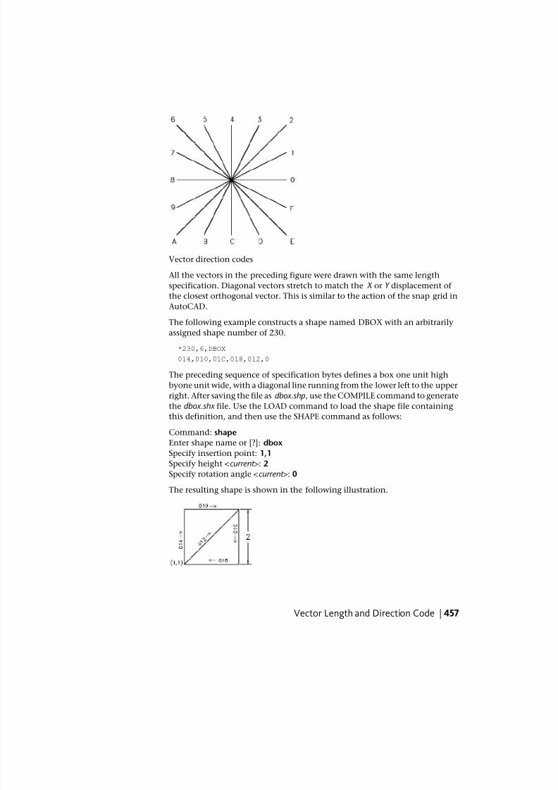
7/23/2019 Acad Customization
http://slidepdf.com/reader/full/acad-customization 465/553
Vector direction codes
All the vectors in the preceding figure were drawn with the same lengthspecification. Diagonal vectors stretch to match the X or Y displacement of
the closest orthogonal vector. This is similar to the action of the snap grid in
AutoCAD.
The following example constructs a shape named DBOX with an arbitrarily
assigned shape number of 230.
*230,6,DBOX
014,010,01C,018,012,0
The preceding sequence of specification bytes defines a box one unit high
byone unit wide, with a diagonal line running from the lower left to the upper
right. After saving the file as dbox.shp, use the COMPILE command to generate
the dbox.shx file. Use the LOAD command to load the shape file containing
this definition, and then use the SHAPE command as follows:
Command: shape
Enter shape name or [?]: dbox
Specify insertion point: 1,1
Specify height <current >: 2
Specify rotation angle <current >: 0
The resulting shape is shown in the following illustration.
Vector Length and Direction Code | 457
7/23/2019 Acad Customization
http://slidepdf.com/reader/full/acad-customization 466/553
Quick Reference
Commands
LOAD
Makes shapes available for use by the SHAPE command.
SHAPE
Inserts a shape from a shape file that has been loaded using LOAD.
Special CodesSpecial codes can be used to create additional geometric forms and specify
certain actions.
Use Special CodesThe second character of the three-character string (the vector length
specification) must be 0, or you can specify the special code number. For
example, 008 and 8 are both valid specifications.
Specification byte codes
DescriptionCode
End of shape definition000
Activate Draw mode (pen down)001
Deactivate Draw mode (pen up)002
Divide vector lengths by next byte003
Multiply vector lengths by next byte004
Push current location onto stack005
Pop current location from stack006
Draw subshape number given by next byte007
X-Y displacement given by next two bytes008
458 | Chapter 8 Shapes and Shape Fonts
7/23/2019 Acad Customization
http://slidepdf.com/reader/full/acad-customization 467/553
Specification byte codes
DescriptionCode
Multiple X-Y displacements, terminated (0,0)009
Octant arc defined by next two bytes00A
Fractional arc defined by next five bytes00B
Arc defined by X-Y displacement and bulge00C
Multiple bulge-specified arcs00D
Process next command only if vertical text00E
Quick Reference
Commands
LOAD
Makes shapes available for use by the SHAPE command.
SHAPE
Inserts a shape from a shape file that has been loaded using LOAD.
Codes 0, 1, and 2: End of Shape and Draw Mode ControlCode 0 marks the end of the shape definition, and Codes 1 and 2 control
Draw mode.
Draw is activated at the start of each shape. When Draw mode is turned on
(code 1), the vectors cause lines to be drawn. When Draw mode is turned off
(code 2), the vectors move to a new location without drawing.
Quick Reference
Commands
LOAD
Makes shapes available for use by the SHAPE command.
Special Codes | 459
7/23/2019 Acad Customization
http://slidepdf.com/reader/full/acad-customization 468/553
SHAPE
Inserts a shape from a shape file that has been loaded using LOAD.
Codes 3 and 4: Size ControlCodes 3 and 4 control the relative size of each vector.
The height specified with the SHAPE command is initially considered the
length of a single orthogonal vector (direction 0, 4, 8, or C). Code 3 divides
vector lengths by the next byte. Code 4 multiplies vector lengths by the next
byte. Codes 3 and 4 are followed by a specification byte containing an integer
scale factor (1 through 255).
If you want the shape height to specify the size of the entire shape, and you
use 10 vector lengths to draw it, you can use 3,10 to scale the height
specification. The scale factor is cumulative within a shape; that is, multiplyingby 2 and again by 6 results in a scale factor of 12. Usually, you should reverse
the effect of your scale factors at the end of the shape, especially for subshapes
and text font shapes. AutoCAD does not reset the scale factor for you.
Quick Reference
Commands
LOAD
Makes shapes available for use by the SHAPE command.
SHAPE
Inserts a shape from a shape file that has been loaded using LOAD.
Codes 5 and 6: Location Save/RestoreCode 5 pushes (saves) and code 6 pops (restores) the current coordinate
position while drawing a shape so that you can return to it from a later point
in the shape.
You must pop everything you push. The position stack is only four locations
deep. If the stack overflows because of too many pushes or too many missing
pops, the following message is displayed when the shape is drawn.
Position stack overflow in shape nnn
460 | Chapter 8 Shapes and Shape Fonts
7/23/2019 Acad Customization
http://slidepdf.com/reader/full/acad-customization 469/553
Similarly, if you try to pop more locations than have been pushed onto the
stack, the following message is displayed when the shape is drawn.
Position stack underflow in shape nnn
Quick Reference
Commands
LOAD
Makes shapes available for use by the SHAPE command.
SHAPE
Inserts a shape from a shape file that has been loaded using LOAD.
Code 7: SubshapeCode 7 draws the subshape number given by the next byte.
For a non-Unicode font the specification byte following code 7 is a shape
number from 1 to 255. For a Unicode font, code 7 is followed by a Unicode
shape number from 1 to 65535. Unicode shape numbers should be counted
as two bytes (for specific information about the differences between Unicode
and non-Unicode fonts, see Unicode Font Descriptions on page 528).
The shape with that number (in the same shape file) is drawn at this time.
Draw mode is not reset for the new shape. When the subshape is complete,
drawing the current shape resumes.
Quick Reference
Commands
LOAD
Makes shapes available for use by the SHAPE command.
SHAPE
Inserts a shape from a shape file that has been loaded using LOAD.
Codes 8 and 9: X-Y DisplacementsWith codes 8 and 9 you can draw nonstandard vectors using X-Y displacements.
Special Codes | 461
7/23/2019 Acad Customization
http://slidepdf.com/reader/full/acad-customization 470/553
Normal vector specification bytes draw only in the 16 predefined directions,
and the longest length is 15. These restrictions help make shape definitions
efficient but are sometimes limiting. Code 8 specifies the X-Y displacementgiven by the next two bytes. Code 8 must be followed by two specification
bytes in the format:
8,X-displacement,Y-displacement
The X-Y displacements can range from -128 to +127. A leading + is optional,
and you can use parentheses to improve readability. The following example
results in a vector that draws (or moves) 10 units to the left and three units
up.
8,(-10,3)
Following the two displacement specification bytes, the shape returns to
Normal Vector mode.
You can use code 9 to draw a sequence of nonstandard vectors. Code 9 specifies
any number of X-Y displacement pairs. The code sequence is terminated by a
(0,0) pair. The following example draws three nonstandard vectors and returns
to Normal Vector mode.
9,(3,1),(3,2),(2,-3),(0,0)
You must terminate the sequence of X-Y displacement pairs with a (0,0) pair
in order for AutoCAD to recognize any Normal Vectors or special codes that
follow.
Quick Reference
Commands
LOAD
Makes shapes available for use by the SHAPE command.
SHAPE
Inserts a shape from a shape file that has been loaded using LOAD.
Code 00A: Octant ArcSpecial code 00A (or 10) uses the next two specification bytes to define an arc.
This is called an octant arc because it spans one or more 45-degree octants ,
starting and ending on an octant boundary. Octants are numbered
462 | Chapter 8 Shapes and Shape Fonts
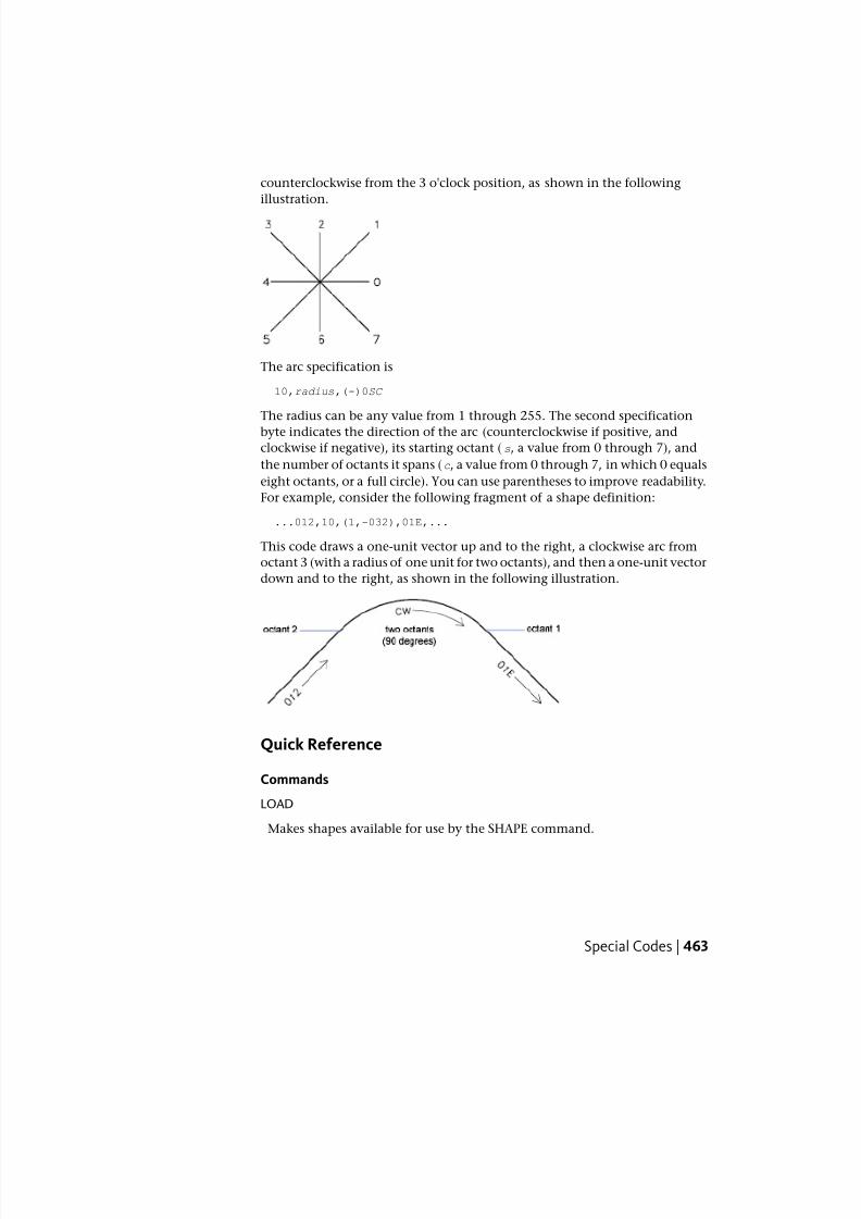
7/23/2019 Acad Customization
http://slidepdf.com/reader/full/acad-customization 471/553
counterclockwise from the 3 o'clock position, as shown in the following
illustration.
The arc specification is
10,radius,(-)0SC
The radius can be any value from 1 through 255. The second specification
byte indicates the direction of the arc (counterclockwise if positive, andclockwise if negative), its starting octant (s, a value from 0 through 7), and
the number of octants it spans (c, a value from 0 through 7, in which 0 equals
eight octants, or a full circle). You can use parentheses to improve readability.
For example, consider the following fragment of a shape definition:
...012,10,(1,-032),01E,...
This code draws a one-unit vector up and to the right, a clockwise arc from
octant 3 (with a radius of one unit for two octants), and then a one-unit vector
down and to the right, as shown in the following illustration.
Quick Reference
Commands
LOAD
Makes shapes available for use by the SHAPE command.
Special Codes | 463

7/23/2019 Acad Customization
http://slidepdf.com/reader/full/acad-customization 472/553
SHAPE
Inserts a shape from a shape file that has been loaded using LOAD.
Code 00B: Fractional ArcSpecial code 00B (11) draws an arc that doesn't necessarily start and end on
an octant boundary.
The definition uses five specification bytes.
11,start_offset,end_offset,high_radius,radius,(-)0SC
The start_offset and end_offset represent how far from an octant boundary
the arc begins or ends. The high_radius represents the most significant eight
bits of the radius; the high radius will be 0 unless the radius is greater than
255 units. Multiply the high_radius value by 256 and add that value to theradius value to generate an arc radius greater than 255. The radius and ending
specification byte are the same as for the octant arc specification (code 00A,
described previously).
You determine the startoffset by calculating the difference in degrees
between the starting octant's boundary (a multiple of 45 degrees) and the start
of the arc. Then, you multiply this difference by 256 and divide by 45. If the
arc starts on an octant boundary, its start offset is 0.
The end offset is calculated in a similar fashion, but you use the number of
degrees from the last octant boundary crossed to the end of the arc. If the arc
ends on an octant boundary, its end offset is 0.
For example, a fractional arc from 55 degrees to 95 degrees with a 3 unit radius
would be coded as follows:
11,(56,28,0,3,012)
Here is the explanation:
start_offset = 56 because ((55 - 45) * 256 / 45) = 56
end_offset = 28 because ((95 - 90) * 256 / 45) = 28
high_radius = 0 because (radius < 255)
radius = 3
starting octant = 1 because arc starts in the 45 degree octant
ending octant = 2 because arc ends in the 90 degree octant
464 | Chapter 8 Shapes and Shape Fonts
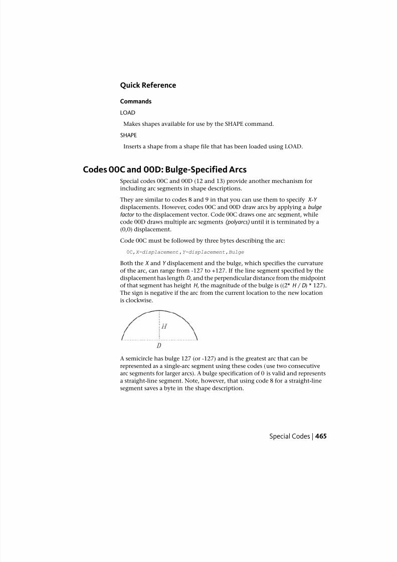
7/23/2019 Acad Customization
http://slidepdf.com/reader/full/acad-customization 473/553
Quick Reference
Commands
LOAD
Makes shapes available for use by the SHAPE command.
SHAPE
Inserts a shape from a shape file that has been loaded using LOAD.
Codes 00C and 00D: Bulge-Specified ArcsSpecial codes 00C and 00D (12 and 13) provide another mechanism for
including arc segments in shape descriptions.
They are similar to codes 8 and 9 in that you can use them to specify X-Y
displacements. However, codes 00C and 00D draw arcs by applying a bulge
factor to the displacement vector. Code 00C draws one arc segment, while
code 00D draws multiple arc segments (polyarcs) until it is terminated by a
(0,0) displacement.
Code 00C must be followed by three bytes describing the arc:
0C,X-displacement,Y-displacement,Bulge
Both the X and Y displacement and the bulge, which specifies the curvature
of the arc, can range from -127 to +127. If the line segment specified by the
displacement has length D, and the perpendicular distance from the midpoint
of that segment has height H , the magnitude of the bulge is ((2* H / D) * 127).
The sign is negative if the arc from the current location to the new locationis clockwise.
A semicircle has bulge 127 (or -127) and is the greatest arc that can be
represented as a single-arc segment using these codes (use two consecutive
arc segments for larger arcs). A bulge specification of 0 is valid and represents
a straight-line segment. Note, however, that using code 8 for a straight-line
segment saves a byte in the shape description.
Special Codes | 465
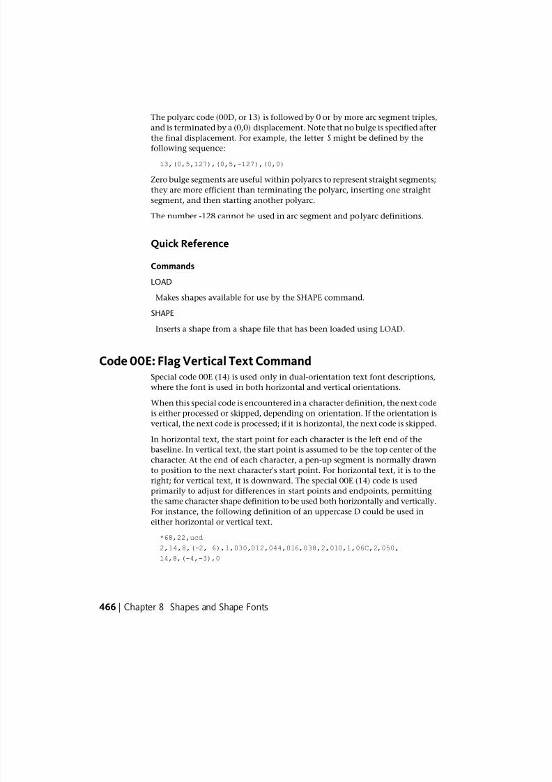
7/23/2019 Acad Customization
http://slidepdf.com/reader/full/acad-customization 474/553
The polyarc code (00D, or 13) is followed by 0 or by more arc segment triples,
and is terminated by a (0,0) displacement. Note that no bulge is specified after
the final displacement. For example, the letter S might be defined by thefollowing sequence:
13,(0,5,127),(0,5,-127),(0,0)
Zero bulge segments are useful within polyarcs to represent straight segments;
they are more efficient than terminating the polyarc, inserting one straight
segment, and then starting another polyarc.
The number -128 cannot be used in arc segment and polyarc definitions.
Quick Reference
Commands
LOAD
Makes shapes available for use by the SHAPE command.
SHAPE
Inserts a shape from a shape file that has been loaded using LOAD.
Code 00E: Flag Vertical Text CommandSpecial code 00E (14) is used only in dual-orientation text font descriptions,
where the font is used in both horizontal and vertical orientations.
When this special code is encountered in a character definition, the next code
is either processed or skipped, depending on orientation. If the orientation isvertical, the next code is processed; if it is horizontal, the next code is skipped.
In horizontal text, the start point for each character is the left end of the
baseline. In vertical text, the start point is assumed to be the top center of the
character. At the end of each character, a pen-up segment is normally drawn
to position to the next character's start point. For horizontal text, it is to the
right; for vertical text, it is downward. The special 00E (14) code is used
primarily to adjust for differences in start points and endpoints, permitting
the same character shape definition to be used both horizontally and vertically.
For instance, the following definition of an uppercase D could be used in
either horizontal or vertical text.
*68,22,ucd
2,14,8,(-2, 6),1,030,012,044,016,038,2,010,1,06C,2,050,14,8,(-4,-3),0
466 | Chapter 8 Shapes and Shape Fonts
7/23/2019 Acad Customization
http://slidepdf.com/reader/full/acad-customization 475/553
Quick Reference
Commands
LOAD
Makes shapes available for use by the SHAPE command.
SHAPE
Inserts a shape from a shape file that has been loaded using LOAD.
Text Font DescriptionsText fonts must include a special shape number 0 that conveys information
about the font itself.
AutoCAD is packaged with numerous text fonts. You can use the STYLEcommand to apply expansion, compression, or obliquing to any of these fonts,
thereby tailoring the characters to your needs. You can draw text of any height,
at any baseline angle, and with either horizontal or vertical orientation using
these fonts.
AutoCAD text fonts are files of shape definitions with shape numbers
corresponding to the ASCII code for each character. Codes 1 through 31 are
for control characters, only one of which is used in AutoCAD text fonts:
10 (LF) The line feed (LF) must drop down one line without drawing. This is
used for repeated TEXT commands, to place succeeding lines below the first
one.
*10,5,lf
2,8,(0,-10),0
Text Font Descriptions | 467

7/23/2019 Acad Customization
http://slidepdf.com/reader/full/acad-customization 476/553
You can modify the spacing of lines by adjusting the downward movement
specified by the LF shape definition.
Text fonts must include a special shape number 0 that conveys information
about the font itself. The format has the following syntax:
*0,4,font-name
above,below ,modes,0
The above value specifies the number of vector lengths above the baseline
that the uppercase letters extend, and below indicates how far the lowercase
letters descend below the baseline. The baseline is similar in concept to the
lines on writing paper. These values define the basic character size and are
used as scale factors for the height specified in the TEXT command.
The modes byte should be 0 for a horizontally oriented font and 2 for a
dual-orientation (horizontal or vertical) font. The special 00E (14) command
code is honored only when modes is set to 2.
The standard fonts supplied with AutoCAD include a few additional characters
required for the AutoCAD dimensioning feature.
%%d Degree symbol (°)
%%p Plus/minus tolerance symbol ( )%%c Circle diameter dimensioning symbol
You can use these and the %%nnn control sequences, as described under TEXT
in the Command Reference .
NOTE AutoCAD draws text characters by their ASCII codes (shape numbers) and
not by name. To save memory, specify the shape name portion of each text shape
definition in lowercase as shown in the following example. (Lowercase names are
not saved in memory.)
*65,11,uca
024,043,04d,02c,2,047,1,040,2,02e,0
Because the shape name uca contains lowercase letters, AutoCAD doesn't save
the name in memory. However, you can use the name for reference when
editing the font definition file. In this example, uca stands for uppercase A.
468 | Chapter 8 Shapes and Shape Fonts
7/23/2019 Acad Customization
http://slidepdf.com/reader/full/acad-customization 477/553
Quick Reference
Commands
LOAD
Makes shapes available for use by the SHAPE command.
SHAPE
Inserts a shape from a shape file that has been loaded using LOAD.
STYLE
Creates, modifies, or specifies text styles.
Sample FilesThis topic contains sample files that help extend the font characters provided
with AutoCAD.
Sample Files | 469

7/23/2019 Acad Customization
http://slidepdf.com/reader/full/acad-customization 478/553
Extended Simplex Roman
470 | Chapter 8 Shapes and Shape Fonts
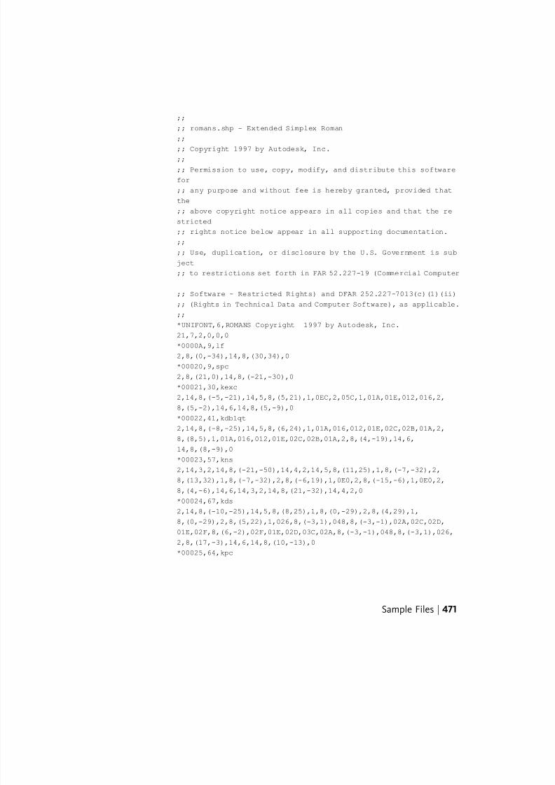
7/23/2019 Acad Customization
http://slidepdf.com/reader/full/acad-customization 479/553
;;
;; romans.shp - Extended Simplex Roman
;;;; Copyright 1997 by Autodesk, Inc.
;;
;; Permission to use, copy, modify, and distribute this software
for
;; any purpose and without fee is hereby granted, provided that
the
;; above copyright notice appears in all copies and that the re
stricted
;; rights notice below appear in all supporting documentation.
;;
;; Use, duplication, or disclosure by the U.S. Government is sub
ject
;; to restrictions set forth in FAR 52.227-19 (Commercial Computer
;; Software - Restricted Rights) and DFAR 252.227-7013(c)(1)(ii)
;; (Rights in Technical Data and Computer Software), as applicable.
;;
*UNIFONT,6,ROMANS Copyright 1997 by Autodesk, Inc.
21,7,2,0,0,0
*0000A,9,lf
2,8,(0,-34),14,8,(30,34),0
*00020,9,spc
2,8,(21,0),14,8,(-21,-30),0
*00021,30,kexc
2,14,8,(-5,-21),14,5,8,(5,21),1,0EC,2,05C,1,01A,01E,012,016,2,
8,(5,-2),14,6,14,8,(5,-9),0
*00022,41,kdblqt
2,14,8,(-8,-25),14,5,8,(6,24),1,01A,016,012,01E,02C,02B,01A,2,
8,(8,5),1,01A,016,012,01E,02C,02B,01A,2,8,(4,-19),14,6,
14,8,(8,-9),0
*00023,57,kns
2,14,3,2,14,8,(-21,-50),14,4,2,14,5,8,(11,25),1,8,(-7,-32),2,
8,(13,32),1,8,(-7,-32),2,8,(-6,19),1,0E0,2,8,(-15,-6),1,0E0,2,
8,(4,-6),14,6,14,3,2,14,8,(21,-32),14,4,2,0
*00024,67,kds
2,14,8,(-10,-25),14,5,8,(8,25),1,8,(0,-29),2,8,(4,29),1,
8,(0,-29),2,8,(5,22),1,026,8,(-3,1),048,8,(-3,-1),02A,02C,02D,
01E,02F,8,(6,-2),02F,01E,02D,03C,02A,8,(-3,-1),048,8,(-3,1),026,
2,8,(17,-3),14,6,14,8,(10,-13),0
*00025,64,kpc
Sample Files | 471
7/23/2019 Acad Customization
http://slidepdf.com/reader/full/acad-customization 480/553
2,14,8,(-12,-21),14,5,8,(21,21),1,8,(-18,-21),2,8,(5,21),1,02E,
02C,02B,029,028,026,024,023,021,020,02F,8,(3,-1),030,8,(3,1),021,
2,8,(-4,-14),1,029,02B,02C,02E,020,021,023,024,026,028,2,8,(7,-7),14,6,14,8,(12,-9),0
*00026,67,kand
2,14,8,(-13,-21),14,5,8,(23,12),1,014,016,018,01A,02B,8,(-2,-5),
8,(-2,-3),02A,029,048,027,016,025,024,023,012,8,(7,4),012,023,
024,025,027,029,02B,02C,8,(1,-3),8,(2,-3),8,(5,-7),02E,02F,020,
012,014,2,8,(3,-2),14,6,14,8,(13,-9),0
*00027,29,kapos
2,14,8,(-5,-25),14,5,8,(6,24),1,01A,016,012,01E,02C,02B,01A,2,
8,(6,-19),14,6,14,8,(5,-9),0
*00028,39,klp
2,14,8,(-7,-25),14,5,8,(11,25),1,02A,8,(-2,-3),04B,8,(-1,-5),04C,
8,(1,-5),04D,8,(2,-3),02E,2,8,(3,7),14,6,14,8,(7,-16),0
*00029,39,krp2,14,8,(-7,-25),14,5,8,(3,25),1,02E,8,(2,-3),04D,8,(1,-5),04C,
8,(-1,-5),04B,8,(-2,-3),02A,2,8,(11,7),14,6,14,8,(7,-16),0
*0002A,37,kas
2,14,8,(-8,-21),14,5,8,(8,21),1,0CC,2,8,(-5,9),1,8,(10,-6),2,064,
1,8,(-10,-6),2,8,(13,-12),14,6,14,8,(8,-9),0
*0002B,31,kpls
2,14,8,(-13,-18),14,5,8,(13,18),1,8,(0,-18),2,096,1,8,(18,0),2,
8,(4,-9),14,6,14,8,(13,-9),0
*0002C,29,kcma
2,14,8,(-5,-2),14,5,8,(6,1),1,01A,016,012,01E,02C,02B,01A,2,
8,(6,4),14,6,14,8,(5,-13),0
*0002D,25,ksub
2,14,8,(-13,-9),14,5,8,(4,9),1,8,(18,0),2,8,(4,-9),14,6,
14,8,(13,-9),0
*0002E,26,kper
2,14,8,(-5,-2),14,5,8,(5,2),1,01A,01E,012,016,2,8,(5,-2),14,6,
14,8,(5,-9),0
*0002F,25,kdiv
2,14,8,(-11,-25),14,5,8,(20,25),1,8,(-18,-32),2,8,(20,7),14,6,
14,8,(11,-16),0
*00030,62,n0
2,14,8,(-10,-21),14,5,8,(9,21),1,8,(-3,-1),8,(-2,-3),8,(-1,-5),
03C,8,(1,-5),8,(2,-3),8,(3,-1),020,8,(3,1),8,(2,3),8,(1,5),034,
8,(-1,5),8,(-2,3),8,(-3,1),028,2,8,(11,-21),14,6,14,8,(10,-9),0
*00031,27,n1
2,14,8,(-10,-21),14,5,8,(6,17),1,021,032,8,(0,-21),2,8,(9,0),
472 | Chapter 8 Shapes and Shape Fonts
7/23/2019 Acad Customization
http://slidepdf.com/reader/full/acad-customization 481/553
14,6,14,8,(10,-9),0
*00032,37,n2
2,14,8,(-10,-21),14,5,8,(4,16),1,014,023,012,021,040,02F,01E,02D,02C,02B,8,(-2,-3),0AA,0E0,2,8,(3,0),14,6,14,8,(10,-9),0
*00033,46,n3
2,14,8,(-10,-21),14,5,8,(5,21),1,0B0,8,(-6,-8),030,02F,01E,
8,(1,-3),02C,8,(-1,-3),02A,8,(-3,-1),038,8,(-3,1),016,025,2,
8,(17,-4),14,6,14,8,(10,-9),0
*00034,34,n4
2,14,8,(-10,-21),14,5,8,(13,21),1,8,(-10,-14),0F0,2,8,(-5,14),1,
8,(0,-21),2,8,(7,0),14,6,14,8,(10,-9),0
*00035,52,n5
2,14,8,(-10,-21),14,5,8,(15,21),1,0A8,8,(-1,-9),012,8,(3,1),030,
8,(3,-1),02E,8,(1,-3),02C,8,(-1,-3),02A,8,(-3,-1),038,8,(-3,1),
016,025,2,8,(17,-4),14,6,14,8,(10,-9),0
*00036,68,n62,14,8,(-10,-21),14,5,8,(16,18),1,025,8,(-3,1),028,8,(-3,-1),
8,(-2,-3),8,(-1,-5),05C,8,(1,-4),02E,8,(3,-1),010,8,(3,1),022,
8,(1,3),014,8,(-1,3),026,8,(-3,1),018,8,(-3,-1),02A,8,(-1,-3),2,
8,(16,-7),14,6,14,8,(10,-9),0
*00037,31,n7
2,14,8,(-10,-21),14,5,8,(17,21),1,8,(-10,-21),2,8,(-4,21),1,0E0,
2,8,(3,-21),14,6,14,8,(10,-9),0
*00038,66,n8
2,14,8,(-10,-21),14,5,8,(8,21),1,8,(-3,-1),02B,02C,02D,02F,
8,(4,-1),8,(3,-1),02E,02D,03C,02B,01A,8,(-3,-1),048,8,(-3,1),016,
025,034,023,022,8,(3,1),8,(4,1),021,023,024,025,8,(-3,1),048,2,
8,(12,-21),14,6,14,8,(10,-9),0
*00039,68,n9
2,14,8,(-10,-21),14,5,8,(16,14),1,8,(-1,-3),02A,8,(-3,-1),018,
8,(-3,1),026,8,(-1,3),014,8,(1,3),022,8,(3,1),010,8,(3,-1),02E,
8,(1,-4),05C,8,(-1,-5),8,(-2,-3),8,(-3,-1),028,8,(-3,1),025,2,
8,(16,-3),14,6,14,8,(10,-9),0
*0003A,33,kcol
2,14,8,(-5,-14),14,5,8,(5,14),1,01A,01E,012,016,2,0CC,1,01A,01E,
012,016,2,8,(5,-2),14,6,14,8,(5,-9),0
*0003B,38,ksmc
2,14,8,(-5,-14),14,5,8,(5,14),1,01A,01E,012,016,2,8,(1,-13),1,
01A,016,012,01E,02C,02B,01A,2,8,(6,4),14,6,14,8,(5,-13),0
*0003C,28,klt
2,14,8,(-12,-18),14,5,8,(20,18),1,8,(-16,-9),8,(16,-9),2,8,(4,0),
14,6,14,8,(12,-9),0
Sample Files | 473
7/23/2019 Acad Customization
http://slidepdf.com/reader/full/acad-customization 482/553
*0003D,33,keq
2,14,8,(-13,-12),14,5,8,(4,12),1,8,(18,0),2,8,(-18,-6),1,
8,(18,0),2,8,(4,-6),14,6,14,8,(13,-9),0*0003E,28,kgt
2,14,8,(-12,-18),14,5,8,(4,18),1,8,(16,-9),8,(-16,-9),2,8,(20,0),
14,6,14,8,(12,-9),0
*0003F,42,kqm
2,14,8,(-9,-21),14,5,8,(3,16),1,014,023,012,021,040,02F,01E,02D,
02C,02B,01A,049,03C,2,05C,1,01A,01E,012,016,2,8,(9,-2),14,6,
14,8,(9,-9),0
*00040,93,kea
2,14,3,2,14,8,(-27,-42),14,4,2,14,5,8,(18,13),1,025,027,038,029,
01A,02B,03C,02D,01E,02F,030,021,023,2,084,1,0AC,01E,020,022,
8,(1,3),024,8,(-1,3),025,026,027,8,(-3,1),038,8,(-3,-1),029,02A,
02B,8,(-1,-3),03C,8,(1,-3),02D,02E,02F,8,(3,-1),030,8,(3,1),021,
012,2,8,(6,-3),14,6,14,3,2,14,8,(27,-18),14,4,2,0*00041,39,uca
2,14,8,(-9,-21),14,5,8,(9,21),1,8,(-8,-21),2,8,(8,21),1,
8,(8,-21),2,8,(-13,7),1,0A0,2,8,(4,-7),14,6,14,8,(9,-9),0
*00042,70,ucb
2,14,3,2,14,8,(-21,-42),14,4,2,14,5,8,(4,21),1,8,(0,-21),2,
8,(0,21),1,090,8,(3,-1),01E,02D,02C,02B,01A,8,(-3,-1),2,098,1,
090,8,(3,-1),01E,02D,03C,02B,01A,8,(-3,-1),098,2,8,(17,0),14,6,
14,3,2,14,8,(21,-18),14,4,2,0
*00043,55,ucc
2,14,3,2,14,8,(-21,-42),14,4,2,14,5,8,(18,16),1,025,026,027,048,
029,02A,02B,8,(-1,-3),05C,8,(1,-3),02D,02E,02F,040,021,022,023,2,
8,(3,-5),14,6,14,3,2,14,8,(21,-18),14,4,2,0
*00044,61,ucd
2,14,3,2,14,8,(-21,-42),14,4,2,14,5,8,(4,21),1,8,(0,-21),2,
8,(0,21),1,070,8,(3,-1),02E,02D,8,(1,-3),05C,8,(-1,-3),02B,02A,
8,(-3,-1),078,2,8,(17,0),14,6,14,3,2,14,8,(21,-18),14,4,2,0
*00045,55,uce
2,14,3,2,14,8,(-19,-42),14,4,2,14,5,8,(4,21),1,8,(0,-21),2,
8,(0,21),1,0D0,2,8,(-13,-10),1,080,2,8,(-8,-11),1,0D0,2,8,(2,0),
14,6,14,3,2,14,8,(19,-18),14,4,2,0
*00046,37,ucf
2,14,8,(-9,-21),14,5,8,(4,21),1,8,(0,-21),2,8,(0,21),1,0D0,2,
8,(-13,-10),1,080,2,8,(6,-11),14,6,14,8,(9,-9),0
*00047,60,ucg
2,14,3,2,14,8,(-21,-42),14,4,2,14,5,8,(18,16),1,025,026,027,048,
029,02A,02B,8,(-1,-3),05C,8,(1,-3),02D,02E,02F,040,021,022,023,
034,2,058,1,050,2,8,(3,-8),14,6,14,3,2,14,8,(21,-18),14,4,2,0
474 | Chapter 8 Shapes and Shape Fonts
7/23/2019 Acad Customization
http://slidepdf.com/reader/full/acad-customization 483/553
*00048,39,uch
2,14,8,(-11,-21),14,5,8,(4,21),1,8,(0,-21),2,8,(14,21),1,
8,(0,-21),2,8,(-14,11),1,0E0,2,8,(4,-11),14,6,14,8,(11,-9),0*00049,25,uci
2,14,8,(-4,-21),14,5,8,(4,21),1,8,(0,-21),2,8,(4,0),14,6,
14,8,(4,-9),0
*0004A,37,ucj
2,14,8,(-8,-21),14,5,8,(12,21),1,8,(0,-16),8,(-1,-3),01A,029,028,
027,016,8,(-1,3),024,2,8,(14,-7),14,6,14,8,(8,-9),0
*0004B,49,uck
2,14,3,2,14,8,(-21,-42),14,4,2,14,5,8,(4,21),1,8,(0,-21),2,
8,(14,21),1,0EA,2,052,1,8,(9,-12),2,8,(3,0),14,6,14,3,2,
14,8,(21,-18),14,4,2,0
*0004C,43,ucl
2,14,3,2,14,8,(-17,-42),14,4,2,14,5,8,(4,21),1,8,(0,-21),2,8,(0,0),1,0C0,2,8,(1,0),14,6,14,3,2,14,8,(17,-18),14,4,2,0
*0004D,49,ucm
2,14,8,(-12,-21),14,5,8,(4,21),1,8,(0,-21),2,8,(0,21),1,
8,(8,-21),2,8,(8,21),1,8,(-8,-21),2,8,(8,21),1,8,(0,-21),2,
8,(4,0),14,6,14,8,(12,-9),0
*0004E,41,ucn
2,14,8,(-11,-21),14,5,8,(4,21),1,8,(0,-21),2,8,(0,21),1,
8,(14,-21),2,8,(0,21),1,8,(0,-21),2,8,(4,0),14,6,14,8,(11,-9),0
*0004F,50,uco
2,14,8,(-11,-21),14,5,8,(9,21),1,029,02A,02B,8,(-1,-3),05C,
8,(1,-3),02D,02E,02F,040,021,022,023,8,(1,3),054,8,(-1,3),025,
026,027,048,2,8,(13,-21),14,6,14,8,(11,-9),0
*00050,55,ucp
2,14,3,2,14,8,(-21,-42),14,4,2,14,5,8,(4,21),1,8,(0,-21),2,
8,(0,21),1,090,8,(3,-1),01E,02D,03C,02B,01A,8,(-3,-1),098,2,
8,(17,-10),14,6,14,3,2,14,8,(21,-18),14,4,2,0
*00051,56,ucq
2,14,8,(-11,-21),14,5,8,(9,21),1,029,02A,02B,8,(-1,-3),05C,
8,(1,-3),02D,02E,02F,040,021,022,023,8,(1,3),054,8,(-1,3),025,
026,027,048,2,8,(3,-17),1,06E,2,8,(4,2),14,6,14,8,(11,-11),0
*00052,61,ucr
2,14,3,2,14,8,(-21,-42),14,4,2,14,5,8,(4,21),1,8,(0,-21),2,
8,(0,21),1,090,8,(3,-1),01E,02D,02C,02B,01A,8,(-3,-1),098,2,070,
1,8,(7,-11),2,8,(3,0),14,6,14,3,2,14,8,(21,-18),14,4,2,0
*00053,51,ucs
2,14,8,(-10,-21),14,5,8,(17,18),1,026,8,(-3,1),048,8,(-3,-1),02A,
Sample Files | 475
7/23/2019 Acad Customization
http://slidepdf.com/reader/full/acad-customization 484/553
02C,02D,01E,02F,8,(6,-2),02F,01E,02D,03C,02A,8,(-3,-1),048,
8,(-3,1),026,2,8,(17,-3),14,6,14,8,(10,-9),0
*00054,31,uct2,14,8,(-8,-21),14,5,8,(8,21),1,8,(0,-21),2,8,(-7,21),1,0E0,2,
8,(1,-21),14,6,14,8,(8,-9),0
*00055,39,ucu
2,14,8,(-11,-21),14,5,8,(4,21),1,0FC,8,(1,-3),02E,8,(3,-1),020,
8,(3,1),022,8,(1,3),0F4,2,8,(4,-21),14,6,14,8,(11,-9),0
*00056,33,ucv
2,14,8,(-9,-21),14,5,8,(1,21),1,8,(8,-21),2,8,(8,21),1,
8,(-8,-21),2,8,(9,0),14,6,14,8,(9,-9),0
*00057,49,ucw
2,14,8,(-12,-21),14,5,8,(2,21),1,8,(5,-21),2,8,(5,21),1,
8,(-5,-21),2,8,(5,21),1,8,(5,-21),2,8,(5,21),1,8,(-5,-21),2,
8,(7,0),14,6,14,8,(12,-9),0
*00058,33,ucx2,14,8,(-10,-21),14,5,8,(3,21),1,8,(14,-21),2,8,(0,21),1,
8,(-14,-21),2,8,(17,0),14,6,14,8,(10,-9),0
*00059,34,ucy
2,14,8,(-9,-21),14,5,8,(1,21),1,8,(8,-10),0BC,2,8,(8,21),1,
8,(-8,-10),2,8,(9,-11),14,6,14,8,(9,-9),0
*0005A,37,ucz
2,14,8,(-10,-21),14,5,8,(17,21),1,8,(-14,-21),2,8,(0,21),1,0E0,2,
8,(-14,-21),1,0E0,2,8,(3,0),14,6,14,8,(10,-9),0
*0005B,37,klb
2,14,8,(-7,-25),14,5,8,(4,25),1,8,(0,-32),2,8,(0,32),1,070,2,
8,(-7,-32),1,070,2,8,(3,7),14,6,14,8,(7,-16),0
*0005C,25,kbkslsh
2,14,8,(-11,-25),14,5,8,(2,25),1,8,(18,-32),2,8,(2,7),14,6,
14,8,(11,-16),0
*0005D,37,krb
2,14,8,(-7,-25),14,5,8,(9,25),1,8,(0,-32),2,8,(-7,32),1,070,2,
8,(-7,-32),1,070,2,8,(4,7),14,6,14,8,(7,-16),0
*0005E,28,kcaret
2,14,8,(-11,-25),14,5,8,(3,20),1,8,(8,5),8,(8,-5),2,8,(3,-20),
14,6,14,8,(11,-9),0
*0005F,21,kundrl
2,14,8,(-12,-14),14,5,02E,1,8,(20,0),2,022,14,6,14,8,(12,-11),0
*00060,29,krvap
2,14,8,(-5,-25),14,5,8,(4,24),1,01E,012,016,01A,02C,02D,01E,2,
8,(6,-19),14,6,14,8,(5,-9),0
*00061,55,lca
2,14,3,2,14,8,(-19,-28),14,4,2,14,5,8,(15,14),1,0EC,2,0B4,1,026,
476 | Chapter 8 Shapes and Shape Fonts
7/23/2019 Acad Customization
http://slidepdf.com/reader/full/acad-customization 485/553
027,038,029,02A,8,(-1,-3),02C,8,(1,-3),02E,02F,030,021,022,2,
8,(4,-3),14,6,14,3,2,14,8,(19,-18),14,4,2,0
*00062,57,lcb2,14,3,2,14,8,(-19,-42),14,4,2,14,5,8,(4,21),1,8,(0,-21),2,0B4,1,
022,021,030,02F,02E,8,(1,-3),02C,8,(-1,-3),02A,029,038,027,026,2,
8,(15,-3),14,6,14,3,2,14,8,(19,-18),14,4,2,0
*00063,39,lcc
2,14,8,(-9,-14),14,5,8,(15,11),1,026,027,038,029,02A,8,(-1,-3),
02C,8,(1,-3),02E,02F,030,021,022,2,8,(3,-3),14,6,14,8,(9,-9),0
*00064,57,lcd
2,14,3,2,14,8,(-19,-42),14,4,2,14,5,8,(15,21),1,8,(0,-21),2,0B4,
1,026,027,038,029,02A,8,(-1,-3),02C,8,(1,-3),02E,02F,030,021,022,
2,8,(4,-3),14,6,14,3,2,14,8,(19,-18),14,4,2,0
*00065,42,lce
2,14,8,(-9,-14),14,5,8,(3,8),1,0C0,024,025,016,027,038,029,02A,8,(-1,-3),02C,8,(1,-3),02E,02F,030,021,022,2,8,(3,-3),14,6,
14,8,(9,-9),0
*00066,36,lcf
2,14,8,(-6,-21),14,5,8,(10,21),1,028,029,8,(-1,-3),8,(0,-17),2,
8,(-3,14),1,070,2,8,(3,-14),14,6,14,8,(6,-9),0
*00067,66,lcg
2,14,3,2,14,8,(-19,-28),14,4,2,14,5,8,(15,14),1,8,(0,-16),
8,(-1,-3),01A,029,038,027,2,8,(9,17),1,026,027,038,029,02A,
8,(-1,-3),02C,8,(1,-3),02E,02F,030,021,022,2,8,(4,-3),14,6,14,3,
2,14,8,(19,-32),14,4,2,0
*00068,48,lch
2,14,3,2,14,8,(-19,-42),14,4,2,14,5,8,(4,21),1,8,(0,-21),2,0A4,1,
032,021,030,02F,8,(1,-3),0AC,2,8,(4,0),14,6,14,3,2,14,8,(19,-18),
14,4,2,0
*00069,32,lci
2,14,8,(-4,-21),14,5,8,(3,20),1,01E,012,016,01A,2,8,(1,-7),1,0DC,
2,8,(4,0),14,6,14,8,(4,-9),0
*0006A,39,lcj
2,14,8,(-5,-21),14,5,8,(5,20),1,01E,012,016,01A,2,8,(1,-7),1,
8,(0,-16),8,(-1,-3),029,028,2,8,(9,7),14,6,14,8,(5,-16),0
*0006B,49,lck
2,14,3,2,14,8,(-17,-42),14,4,2,14,5,8,(4,21),1,8,(0,-21),2,
8,(10,14),1,0AA,2,042,1,8,(7,-8),2,8,(2,0),14,6,14,3,2,
14,8,(17,-18),14,4,2,0
*0006C,25,lcl
2,14,8,(-4,-21),14,5,8,(4,21),1,8,(0,-21),2,8,(4,0),14,6,
Sample Files | 477
7/23/2019 Acad Customization
http://slidepdf.com/reader/full/acad-customization 486/553
14,8,(4,-9),0
*0006D,45,lcm
2,14,8,(-15,-14),14,5,8,(4,14),1,0EC,2,0A4,1,032,021,030,02F,8,(1,-3),0AC,2,0A4,1,032,021,030,02F,8,(1,-3),0AC,2,8,(4,0),14,6,
14,8,(15,-9),0
*0006E,46,lcn
2,14,3,2,14,8,(-19,-28),14,4,2,14,5,8,(4,14),1,0EC,2,0A4,1,032,
021,030,02F,8,(1,-3),0AC,2,8,(4,0),14,6,14,3,2,14,8,(19,-18),
14,4,2,0
*0006F,58,lco
2,14,3,2,14,8,(-19,-28),14,4,2,14,5,8,(8,14),1,029,02A,8,(-1,-3),
02C,8,(1,-3),02E,02F,030,021,022,8,(1,3),024,8,(-1,3),026,027,
038,2,8,(11,-14),14,6,14,3,2,14,8,(19,-18),14,4,2,0
*00070,59,lcp
2,14,3,2,14,8,(-19,-28),14,4,2,14,5,8,(4,14),1,8,(0,-21),2,
8,(0,18),1,022,021,030,02F,02E,8,(1,-3),02C,8,(-1,-3),02A,029,038,027,026,2,8,(15,-3),14,6,14,3,2,14,8,(19,-32),14,4,2,0
*00071,59,lcq
2,14,3,2,14,8,(-19,-28),14,4,2,14,5,8,(15,14),1,8,(0,-21),2,
8,(0,18),1,026,027,038,029,02A,8,(-1,-3),02C,8,(1,-3),02E,02F,
030,021,022,2,8,(4,-3),14,6,14,3,2,14,8,(19,-32),14,4,2,0
*00072,44,lcr
2,14,3,2,14,8,(-13,-28),14,4,2,14,5,8,(4,14),1,0EC,2,084,1,
8,(1,3),022,021,030,2,8,(1,-14),14,6,14,3,2,14,8,(13,-18),14,4,2,
0
*00073,60,lcs
2,14,3,2,14,8,(-17,-28),14,4,2,14,5,8,(14,11),1,025,8,(-3,1),038,
8,(-3,-1),02B,02D,02F,8,(5,-1),02F,02D,01C,02B,8,(-3,-1),038,
8,(-3,1),025,2,8,(14,-3),14,6,14,3,2,14,8,(17,-18),14,4,2,0
*00074,36,lct
2,14,8,(-6,-21),14,5,8,(5,21),1,8,(0,-17),8,(1,-3),02F,020,2,
8,(-8,14),1,070,2,8,(3,-14),14,6,14,8,(6,-9),0
*00075,46,lcu
2,14,3,2,14,8,(-19,-28),14,4,2,14,5,8,(4,14),1,0AC,8,(1,-3),02F,
030,021,032,2,0A4,1,0EC,2,8,(4,0),14,6,14,3,2,14,8,(19,-18),14,4,
2,0
*00076,33,lcv
2,14,8,(-8,-14),14,5,8,(2,14),1,8,(6,-14),2,8,(6,14),1,
8,(-6,-14),2,8,(8,0),14,6,14,8,(8,-9),0
*00077,49,lcw
2,14,8,(-11,-14),14,5,8,(3,14),1,8,(4,-14),2,8,(4,14),1,
8,(-4,-14),2,8,(4,14),1,8,(4,-14),2,8,(4,14),1,8,(-4,-14),2,
8,(7,0),14,6,14,8,(11,-9),0
478 | Chapter 8 Shapes and Shape Fonts
7/23/2019 Acad Customization
http://slidepdf.com/reader/full/acad-customization 487/553
*00078,43,lcx
2,14,3,2,14,8,(-17,-28),14,4,2,14,5,8,(3,14),1,8,(11,-14),2,0E4,
1,8,(-11,-14),2,8,(14,0),14,6,14,3,2,14,8,(17,-18),14,4,2,0*00079,37,lcy
2,14,8,(-8,-14),14,5,8,(2,14),1,8,(6,-14),2,8,(6,14),1,
8,(-6,-14),04B,02A,029,018,2,8,(15,7),14,6,14,8,(8,-16),0
*0007A,47,lcz
2,14,3,2,14,8,(-17,-28),14,4,2,14,5,8,(14,14),1,8,(-11,-14),2,
0E4,1,0B0,2,8,(-11,-14),1,0B0,2,8,(3,0),14,6,14,3,2,
14,8,(17,-18),14,4,2,0
*0007B,54,klbr
2,14,3,2,14,8,(-13,-50),14,4,2,14,5,8,(9,25),1,029,01A,02B,02C,
02D,01E,02D,02C,02A,029,02F,02E,02C,02B,01A,02B,02C,02D,01E,02F,
2,8,(5,7),14,6,14,3,2,14,8,(13,-32),14,4,2,0
*0007C,25,kvbar
2,14,8,(-4,-25),14,5,8,(4,25),1,8,(0,-32),2,8,(4,7),14,6,14,8,(4,-16),0
*0007D,54,krbr
2,14,3,2,14,8,(-15,-50),14,4,2,14,5,8,(5,25),1,02F,01E,02D,02C,
02B,01A,02B,02C,02E,02F,029,02A,02C,02D,01E,02D,02C,02B,01A,029,
2,8,(9,7),14,6,14,3,2,14,8,(15,-32),14,4,2,0
*0007E,37,ktlde
2,14,8,(-13,-14),14,5,8,(4,6),1,024,8,(1,3),021,020,02F,8,(4,-3),
02F,020,021,023,024,2,8,(4,-12),14,6,14,8,(13,-9),0
*00080,4,keuroRef
7,020AC,0
*000A0,9,spc
2,8,(21,0),14,8,(-21,-30),0
*000A1,28,kiexc
2,14,8,(-5,-21),14,5,050,1,0E4,2,054,1,012,016,01A,01E,2,
8,(8,-19),14,6,14,8,(5,-9),0
*000A2,43,kcent
2,14,8,(-9,-17),14,5,03E,1,8,(12,20),2,06C,1,026,027,038,029,02A,
8,(-1,-3),02C,8,(1,-3),02E,02F,030,021,022,2,8,(3,-3),14,6,
14,8,(9,-9),0
*000A3,37,kpound
2,14,8,(-10,-21),14,5,8,(12,18),1,025,027,029,02B,0FC,03A,0E0,2,
8,(-8,10),1,068,014,060,2,8,(9,-11),14,6,14,8,(10,-9),0
*000A5,44,kyen
2,14,8,(-12,-21),14,5,8,(1,21),1,8,(8,-10),0BC,2,8,(8,21),1,
8,(-8,-10),2,078,1,0E0,2,8,(-14,-3),1,0E0,2,8,(6,-8),14,6,
14,8,(12,-9),0
*000A7,78,kpar
Sample Files | 479
7/23/2019 Acad Customization
http://slidepdf.com/reader/full/acad-customization 488/553
2,14,8,(-10,-25),14,5,060,1,012,016,01A,01C,02D,01E,02F,020,021,
012,023,014,025,016,8,(-8,4),016,025,014,023,012,021,010,
8,(8,-4),2,094,028,1,01A,01E,012,014,025,016,027,028,029,01A,02B,01C,02D,01E,8,(8,-4),01E,02D,01C,02B,01A,029,018,8,(-8,4),2,
8,(16,-9),14,6,14,8,(10,-13),0
*000AA,51,lcau
2,14,8,-7,-21,14,5,8,4,14,3,2,1,0A0,2,054,1,02A,029,028,027,016,
8,-1,3,024,8,1,3,012,021,020,02F,02E,2,034,1,0CC,2,4,2,8,4,-15,
14,6,14,8,7,-9,0
*000AB,25,kfrew
2,14,8,(-9,-14),14,5,0A0,1,076,072,2,050,1,07A,07E,2,030,14,6,
14,8,(9,-9),0
*000B0,25,kdeg
2,14,8,(-3,-21),14,5,8,(1,19),1,10,(2,64),2,8,(8,-19),14,6,
14,8,(3,-9),0
*000B1,39,kpls-min2,14,8,(-13,-21),14,5,8,(13,21),1,8,(0,-18),2,096,1,8,(18,0),2,
8,(-18,-11),1,8,(18,0),2,8,(4,-1),14,6,14,8,(13,-9),0
*000B5,48,kmicro
2,14,3,2,14,8,(-19,-28),14,4,2,14,5,07C,1,022,8,(3,19),0AC,
8,(1,-3),02F,030,021,032,2,0A4,1,0EC,2,8,(4,0),14,6,14,3,2,
14,8,(19,-32),14,4,2,0
*000BA,56,lcou
2,14,8,-7,-21,14,5,8,4,14,3,2,1,0A0,2,8,-4,14,1,028,029,01A,8,-1,
-3,02C,8,1,-3,01E,02F,020,021,012,8,1,3,024,8,-1,3,016,027,2,4,2,
8,6,-21,14,6,14,8,7,-9,0
*000BB,25,kffrw
2,14,8,(-9,-14),14,5,030,1,072,076,2,050,1,07E,07A,2,0A0,14,6,
14,8,(9,-9),0
*000BC,43,kquart
2,14,8,(-14,-25),14,5,8,(4,21),1,021,022,0EC,2,8,(-2,-14),1,
8,(16,29),2,8,(2,-23),1,0A8,8,(7,9),0EC,2,8,(7,3),14,6,
14,8,(14,-13),0
*000BD,50,khalf
2,14,8,(-14,-25),14,5,8,(4,21),1,021,022,0EC,2,8,(-2,-14),1,
8,(16,29),2,8,(-6,-18),1,014,023,021,020,02F,02D,01C,02B,
8,(-7,-8),080,2,8,(4,3),14,6,14,8,(14,-13),0
*000BF,47,kiqm
2,14,8,(-9,-21),14,5,8,(13,4),1,016,012,01E,01C,02B,01A,029,038,
8,(-3,1),025,024,023,012,021,022,034,2,054,1,012,016,01A,01E,2,
8,(8,-19),14,6,14,8,(9,-9),0
*000C0,43,uc^
2,14,8,(-9,-25),14,5,8,(9,23),1,047,2,04E,1,8,(-8,-21),2,
480 | Chapter 8 Shapes and Shape Fonts
7/23/2019 Acad Customization
http://slidepdf.com/reader/full/acad-customization 489/553
8,(8,21),1,8,(8,-21),2,8,(-13,7),1,0A0,2,8,(4,-7),14,6,
14,8,(9,-9),0
*000C1,43,uc^2,14,8,(-9,-25),14,5,8,(9,23),1,041,2,04A,1,8,(-8,-21),2,
8,(8,21),1,8,(8,-21),2,8,(-13,7),1,0A0,2,8,(4,-7),14,6,
14,8,(9,-9),0
*000C2,44,uc
2,14,8,(-9,-25),14,5,8,(5,23),1,041,04F,2,049,1,8,(-8,-21),2,
8,(8,21),1,8,(8,-21),2,8,(-13,7),1,0A0,2,8,(4,-7),14,6,
14,8,(9,-9),0
*000C3,55,uc^
2,14,8,(-9,-25),14,5,8,(4,22),5,1,023,10,(2,-50),01E,10,(2,82),
023,2,6,8,(5,-1),1,8,(-8,-21),2,8,(8,21),1,8,(8,-21),2,8,(-13,7),
1,0A0,2,8,(4,-7),14,6,14,8,(9,-9),0
*000C4,53,uc„
2,14,8,(-9,-25),14,5,8,(4,24),1,01E,012,016,01A,2,080,1,01E,012,016,01A,2,03A,1,8,(-8,-21),2,8,(8,21),1,8,(8,-21),2,8,(-13,7),1,
0A0,2,8,(4,-7),14,6,14,8,(9,-9),0
*000C5,45,uc^
2,14,8,(-9,-25),14,5,8,(7,23),1,10,(2,64),2,02E,1,8,(-8,-21),2,
8,(8,21),1,8,(8,-21),2,8,(-13,7),1,0A0,2,8,(4,-7),14,6,
14,8,(9,-9),0
*000C6,45,uc^
2,14,8,(-9,-21),14,5,010,1,8,(8,21),8,(0,-21),080,2,8,(-8,7),1,
058,2,8,(5,4),1,050,2,8,(-5,10),1,080,2,8,(2,-21),14,6,
14,8,(9,-9),0
*000C7,65,uc‡
2,14,3,2,14,8,(-21,-42),14,4,2,14,5,8,(18,16),1,025,026,027,048,
029,02A,02B,8,(-1,-3),05C,8,(1,-3),02D,02E,02F,040,021,022,023,2,
8,(-9,-11),1,01E,030,012,024,016,028,034,2,0A0,14,6,14,3,2,
14,8,(21,-32),14,4,2,0
*000C8,53,uc^
2,14,3,2,14,8,(-19,-50),14,4,2,14,5,8,(6,25),1,8,(9,-4),2,
8,(2,-2),1,0D8,8,(0,-19),0D0,2,8,(-13,10),1,080,2,8,(7,-10),14,6,
14,3,2,14,8,(19,-18),14,4,2,0
*000C9,53,uc^
2,14,3,2,14,8,(-19,-50),14,4,2,14,5,8,(6,21),1,8,(9,4),2,
8,(2,-6),1,0D8,8,(0,-19),0D0,2,8,(-13,10),1,080,2,8,(7,-10),14,6,
14,3,2,14,8,(19,-18),14,4,2,0
*000CA,53,uc^
2,14,3,2,14,8,(-19,-50),14,4,2,14,5,8,(6,23),1,041,010,04F,2,
8,(2,-2),1,0D8,8,(0,-21),0D0,2,8,(-13,11),1,080,2,8,(7,-11),14,6,
14,3,2,14,8,(19,-18),14,4,2,0
Sample Files | 481
7/23/2019 Acad Customization
http://slidepdf.com/reader/full/acad-customization 490/553
*000CB,61,uc^
2,14,3,2,14,8,(-19,-50),14,4,2,14,5,8,(6,24),1,01E,012,016,01A,2,
070,1,01E,012,016,01A,2,8,(4,-3),1,0D8,8,(0,-21),0D0,2,8,(-13,11),1,080,2,8,(7,-11),14,6,14,3,2,14,8,(19,-18),14,4,2,0
*000CC,29,uc^
2,14,8,(-4,-25),14,5,8,(4,23),1,026,2,04D,1,8,(0,-21),2,8,(4,0),
14,6,14,8,(4,-9),0
*000CD,29,uc^
2,14,8,(-4,-25),14,5,8,(4,23),1,022,2,04B,1,8,(0,-21),2,8,(4,0),
14,6,14,8,(4,-9),0
*000CE,30,uc^
2,14,8,(-4,-25),14,5,8,(2,23),1,022,02E,2,02A,1,8,(0,-21),2,
8,(4,0),14,6,14,8,(4,-9),0
*000CF,41,uc^
2,14,8,(-4,-25),14,5,8,(1,24),1,01E,012,016,01A,2,040,1,01E,012,
016,01A,2,8,(-1,-3),1,8,(0,-21),2,8,(4,0),14,6,14,8,(4,-9),0*000D1,41,uc
2,14,8,(-11,-25),14,5,040,1,8,(0,19),8,(14,-19),8,(0,19),2,
8,(-13,3),1,032,010,8,(4,-3),010,032,2,8,(5,-25),14,6,
14,8,(11,-9),0
*000D2,44,uc^
2,14,8,(-11,-25),14,5,8,(6,25),1,08F,2,8,(-6,-2),1,029,02A,04B,
05C,04D,02E,02F,040,021,022,043,054,045,026,027,048,2,8,(13,-19),
14,6,14,8,(11,-9),0
*000D3,42,uc^
2,14,8,(-11,-25),14,5,8,(6,21),1,081,2,06A,1,029,02A,04B,05C,04D,
02E,02F,040,021,022,043,054,045,026,027,048,2,8,(13,-19),14,6,
14,8,(11,-9),0
*000D4,57,uc^
2,14,8,(-11,-25),14,5,8,(6,23),1,041,04F,2,8,(-6,-2),1,029,02A,
02B,8,(-1,-3),05C,8,(1,-3),02D,02E,02F,040,021,022,023,8,(1,3),
054,8,(-1,3),025,026,027,048,2,8,(13,-21),14,6,14,8,(11,-9),0
*000D5,66,uc^
2,14,8,(-11,-25),14,5,8,(6,22),5,1,023,10,(2,-50),01E,10,(2,82),
023,2,6,8,(3,-1),1,029,02A,02B,8,(-1,-3),05C,8,(1,-3),02D,02E,
02F,040,021,022,023,8,(1,3),054,8,(-1,3),025,026,027,048,2,
8,(13,-21),14,6,14,8,(11,-9),0
*000D6,66,uc^
2,14,8,(-11,-25),14,5,8,(6,24),1,01E,012,016,01A,2,080,1,01E,012,
016,01A,2,8,(-5,-3),1,029,02A,02B,8,(-1,-3),05C,8,(1,-3),02D,02E,
02F,040,021,022,023,8,(1,3),054,8,(-1,3),025,026,027,048,2,
8,(13,-21),14,6,14,8,(11,-9),0
*000D8,54,uc›
482 | Chapter 8 Shapes and Shape Fonts
7/23/2019 Acad Customization
http://slidepdf.com/reader/full/acad-customization 491/553
2,14,8,(-11,-21),8,(9,21),1,029,02A,02B,8,(-1,-3),05C,8,(1,-3),
02D,02E,02F,040,021,022,023,8,(1,3),054,8,(-1,3),025,026,027,048,
2,8,(-6,-21),1,8,(16,21),2,8,(3,-21),14,8,(-11,-9),0*000D9,43,uc^
2,14,8,(-11,-25),14,5,8,(15,21),1,087,2,06B,1,0DC,8,(1,-3),02E,
8,(3,-1),020,8,(3,1),022,8,(1,3),0D4,2,8,(4,-19),14,6,
14,8,(11,-9),0
*000DA,45,uc^
2,14,8,(-11,-25),14,5,8,(15,25),1,089,2,8,(-3,-2),1,0DC,8,(1,-3),
02E,8,(3,-1),020,8,(3,1),022,8,(1,3),0D4,2,8,(4,-19),14,6,
14,8,(11,-9),0
*000DB,46,uc^
2,14,8,(-11,-25),14,5,8,(15,23),1,047,049,2,8,(-3,-2),1,0FC,
8,(1,-3),02E,8,(3,-1),020,8,(3,1),022,8,(1,3),0F4,2,8,(4,-21),
14,6,14,8,(11,-9),0
*000DC,55,uc^2,14,8,(-11,-25),14,5,8,(14,24),1,01E,012,016,01A,2,088,1,01E,
012,016,01A,2,8,(-2,-3),1,0FC,8,(1,-3),02E,8,(3,-1),020,8,(3,1),
022,8,(1,3),0F4,2,8,(4,-21),14,6,14,8,(11,-9),0
*000DD,38,uc^
2,14,8,(-9,-25),14,5,8,(13,25),1,089,2,049,1,8,(8,-9),0AC,2,
8,(8,19),1,8,(-8,-9),2,8,(9,-10),14,6,14,8,(9,-9),0
*000DF,53,kgers
2,14,8,(-9,-21),14,5,030,1,012,8,(0,16),023,012,021,020,02F,01E,
02D,02C,02B,01A,029,028,2,020,1,8,(3,-1),01E,02D,03C,02B,01A,029,
028,027,016,012,01E,2,8,(10,-2),14,6,14,8,(9,-9),0
*000E0,63,lc…
2,14,3,2,14,8,(-19,-42),14,4,2,14,5,8,(5,21),1,8,(8,-4),2,
8,(2,-3),1,0EC,2,0B4,1,026,027,038,029,02A,8,(-1,-3),02C,
8,(1,-3),02E,02F,030,021,022,2,8,(4,-3),14,6,14,3,2,
14,8,(19,-18),14,4,2,0
*000E1,63,lc
2,14,3,2,14,8,(-19,-42),14,4,2,14,5,8,(5,17),1,8,(8,4),2,
8,(2,-7),1,0EC,2,0B4,1,026,027,038,029,02A,8,(-1,-3),02C,
8,(1,-3),02E,02F,030,021,022,2,8,(4,-3),14,6,14,3,2,
14,8,(19,-18),14,4,2,0
*000E2,64,lc^
2,14,3,2,14,8,(-19,-42),14,4,2,14,5,8,(5,18),1,8,(4,3),8,(4,-3),
2,04D,1,0EC,2,0B4,1,026,027,038,029,02A,8,(-1,-3),02C,8,(1,-3),
02E,02F,030,021,022,2,8,(4,-3),14,6,14,3,2,14,8,(19,-18),14,4,2,0
*000E3,63,lcƒ
2,14,3,2,14,8,(-19,-42),14,4,2,14,5,8,(4,18),1,032,010,03E,010,
Sample Files | 483
7/23/2019 Acad Customization
http://slidepdf.com/reader/full/acad-customization 492/553
032,2,07C,1,0EC,2,0B4,1,026,027,038,029,02A,8,(-1,-3),02C,
8,(1,-3),02E,02F,030,021,022,2,8,(4,-3),14,6,14,3,2,
14,8,(19,-18),14,4,2,0*000E4,71,lc„
2,14,3,2,14,8,(-19,-42),14,4,2,14,5,8,(4,20),1,01E,012,016,01A,2,
090,1,01E,012,016,01A,2,8,(2,-6),1,0EC,2,0B4,1,026,027,038,029,
02A,8,(-1,-3),02C,8,(1,-3),02E,02F,030,021,022,2,8,(4,-3),14,6,
14,3,2,14,8,(19,-18),14,4,2,0
*000E5,63,lc†
2,14,3,2,14,8,(-19,-42),14,4,2,14,5,8,(7,19),1,10,(2,64),2,
8,(8,-5),1,0EC,2,0B4,1,026,027,038,029,02A,8,(-1,-3),02C,
8,(1,-3),02E,02F,030,021,022,2,8,(4,-3),14,6,14,3,2,
14,8,(19,-18),14,4,2,0
*000E6,51,lc
2,14,8,(-10,-14),14,5,8,(10,8),1,070,014,8,(-1,3),026,028,02A,
026,028,02A,8,(-1,-3),04C,8,(1,-3),02E,020,022,02E,020,021,023,2,8,(-7,11),1,0EC,2,0A0,14,6,14,8,(10,-9),0
*000E7,49,lc‡
2,14,8,(-9,-14),14,5,8,(15,11),1,026,027,038,029,02A,8,(-1,-3),
02C,8,(1,-3),02E,02F,030,021,022,2,8,(-8,-9),1,01E,030,012,024,
016,028,034,2,090,14,6,14,8,(9,-16),0
*000E8,48,lcŠ
2,14,8,(-9,-21),14,5,8,(5,21),1,08F,2,8,(-10,-9),1,0C0,024,025,
016,027,038,029,02A,8,(-1,-3),02C,8,(1,-3),02E,02F,030,021,022,2,
8,(3,-3),14,6,14,8,(9,-9),0
*000E9,48,lc‚
2,14,8,(-9,-21),14,5,8,(5,17),1,081,2,8,(-10,-13),1,0C0,024,025,
016,027,038,029,02A,8,(-1,-3),02C,8,(1,-3),02E,02F,030,021,022,2,
8,(3,-3),14,6,14,8,(9,-9),0
*000EA,51,lcˆ
2,14,8,(-9,-21),14,5,8,(5,18),1,8,(4,3),8,(4,-3),2,0AA,1,0C0,024,
025,016,027,038,029,02A,8,(-1,-3),02C,8,(1,-3),02E,02F,030,021,
022,2,8,(3,-3),14,6,14,8,(9,-9),0
*000EB,58,lc‰
2,14,8,(-9,-21),14,5,8,(4,20),1,01E,012,016,01A,2,080,1,01E,012,
016,01A,2,8,(-9,-12),1,0C0,024,025,016,027,038,029,02A,8,(-1,-3),
02C,8,(1,-3),02E,02F,030,021,022,2,8,(3,-3),14,6,14,8,(9,-9),0
*000EC,27,lc_
2,14,8,(-7,-21),14,5,8,(3,21),1,08F,2,04A,1,0DC,2,8,(4,0),14,6,
14,8,(7,-9),0
*000ED,27,lc
2,14,8,(-7,-21),14,5,8,(3,17),1,081,2,08B,1,0DC,2,8,(4,0),14,6,
14,8,(7,-9),0
484 | Chapter 8 Shapes and Shape Fonts
7/23/2019 Acad Customization
http://slidepdf.com/reader/full/acad-customization 493/553
*000EE,34,lcŒ
2,14,8,(-7,-21),14,5,8,(3,18),1,8,(4,3),8,(4,-3),2,8,(-4,-5),1,
0DC,2,8,(4,0),14,6,14,8,(7,-9),0*000EF,39,lc‹
2,14,8,(-7,-21),14,5,8,(3,20),1,01E,012,016,01A,2,060,1,01E,012,
016,01A,2,8,(-2,-7),1,0DC,2,8,(4,0),14,6,14,8,(7,-9),0
*000F1,56,lc
2,14,3,2,14,8,(-19,-42),14,4,2,14,5,8,(4,18),1,032,010,03E,010,
032,2,8,(-11,-7),1,0EC,2,0A4,1,032,021,030,02F,8,(1,-3),0AC,2,
8,(4,0),14,6,14,3,2,14,8,(19,-18),14,4,2,0
*000F2,64,lc•
2,14,3,2,14,8,(-19,-42),14,4,2,14,5,8,(5,21),1,8,(9,-4),2,069,1,
029,02A,8,(-1,-3),02C,8,(1,-3),02E,02F,030,021,022,8,(1,3),024,
8,(-1,3),026,027,038,2,8,(11,-14),14,6,14,3,2,14,8,(19,-18),14,4,
2,0
*000F3,66,lc2,14,3,2,14,8,(-19,-42),14,4,2,14,5,8,(5,17),1,8,(9,4),2,
8,(-6,-7),1,029,02A,8,(-1,-3),02C,8,(1,-3),02E,02F,030,021,022,
8,(1,3),024,8,(-1,3),026,027,038,2,8,(11,-14),14,6,14,3,2,
14,8,(19,-18),14,4,2,0
*000F4,73,lc“
2,14,3,2,14,8,(-19,-42),14,4,2,14,5,8,(5,18),3,2,1,8,(9,6),
8,(9,-6),2,4,2,8,(-6,-4),1,029,02A,8,(-1,-3),02C,8,(1,-3),02E,
02F,030,021,022,8,(1,3),024,8,(-1,3),026,027,038,2,8,(11,-14),
14,6,14,3,2,14,8,(19,-18),14,4,2,0
*000F5,68,lc^
2,14,3,2,14,8,(-19,-42),14,4,2,14,5,8,(4,18),1,032,010,03E,010,
032,2,8,(-7,-7),1,029,02A,8,(-1,-3),02C,8,(1,-3),02E,02F,030,021,
022,8,(1,3),024,8,(-1,3),026,027,038,2,8,(11,-14),14,6,14,3,2,
14,8,(19,-18),14,4,2,0
*000F6,74,lc”
2,14,3,2,14,8,(-19,-42),14,4,2,14,5,8,(4,20),1,01E,012,016,01A,2,
090,1,01E,012,016,01A,2,8,(-5,-6),1,029,02A,8,(-1,-3),02C,
8,(1,-3),02E,02F,030,021,022,8,(1,3),024,8,(-1,3),026,027,038,2,
8,(11,-14),14,6,14,3,2,14,8,(19,-18),14,4,2,0
*000F7,41,kto
2,14,8,(-9,-14),14,5,8,(8,13),1,01E,012,016,01A,2,8,(-5,-6),1,
0C0,2,8,(-7,-6),1,01E,012,016,01A,2,8,(10,-1),14,6,14,8,(9,-9),0
*000F8,24,lc›
7,06F,2,8,(-3,14),14,8,(9,9),1,8,(-13,-14),2,8,(17,0),
14,8,(-10,-9),0
*000F9,54,lc—
2,14,3,2,14,8,(-19,-42),14,4,2,14,5,8,(5,21),1,8,(9,-4),2,
Sample Files | 485
7/23/2019 Acad Customization
http://slidepdf.com/reader/full/acad-customization 494/553
8,(-10,-3),1,0AC,8,(1,-3),02F,030,021,032,2,0A4,1,0EC,2,8,(4,0),
14,6,14,3,2,14,8,(19,-18),14,4,2,0
*000FA,54,lc2,14,3,2,14,8,(-19,-42),14,4,2,14,5,8,(5,17),1,8,(9,4),2,
8,(-10,-7),1,0AC,8,(1,-3),02F,030,021,032,2,0A4,1,0EC,2,8,(4,0),
14,6,14,3,2,14,8,(19,-18),14,4,2,0
*000FB,61,lc-
2,14,3,2,14,8,(-19,-42),14,4,2,14,5,8,(5,18),3,2,1,8,(9,6),
8,(9,-6),4,2,2,8,(-10,-4),1,0AC,8,(1,-3),02F,030,021,032,2,0A4,1,
0EC,2,8,(4,0),14,6,14,3,2,14,8,(19,-18),14,4,2,0
*000FC,62,lc_
2,14,3,2,14,8,(-19,-42),14,4,2,14,5,8,(4,20),1,01E,012,016,01A,2,
090,1,01E,012,016,01A,2,8,(-9,-6),1,0AC,8,(1,-3),02F,030,021,032,
2,0A4,1,0EC,2,8,(4,0),14,6,14,3,2,14,8,(19,-18),14,4,2,0
*000FD,43,lc^
2,14,8,(-8,-14),14,5,8,(2,14),5,032,1,8,(9,4),6,8,(6,-14),2,8,(6,14),1,8,(-6,-14),04B,02A,029,018,2,8,(15,7),14,6,
14,8,(8,-16),0
*000FF,53,lc˜
2,14,8,(-8,-21),14,5,8,(3,20),1,01E,012,016,01A,2,080,1,01E,012,
016,01A,2,8,(-9,-6),1,8,(6,-14),2,8,(6,14),1,8,(-6,-14),04B,02A,
029,018,2,8,(15,7),14,6,14,8,(8,-16),0
*00104,50,c164
2,14,8,(-9,-21),14,5,8,(9,21),1,8,(-8,-21),2,8,(8,21),1,
8,(8,-21),3,2,10,(5,36),1,10,(5,-100),4,2,2,8,(-13,7),1,0A0,2,
8,(4,-7),14,6,14,8,(9,-9),0
*00105,66,c165
2,14,3,2,14,8,(-19,-28),14,4,2,14,5,8,(15,14),1,0EC,3,2,10,
(5,36),2,10,(5,-100),4,2,2,0B4,1,026,027,038,029,02A,8,(-1,-3),
02C,8,(1,-3),02E,02F,030,021,022,2,8,(4,-3),14,6,14,3,2,
14,8,(19,-18),14,4,2,0
*00106,71,c143
2,14,3,2,14,8,(-21,-42),14,4,2,14,5,3,2,2,8,(18,48),1,8,(8,6),2,
8,(-26,-54),4,2,8,(18,16),1,025,026,027,048,029,02A,02B,
8,(-1,-3),05C,8,(1,-3),02D,02E,02F,040,021,022,023,2,8,(3,-5),
14,6,14,3,2,14,8,(21,-18),14,4,2,0
*00107,54,c134
2,14,8,(-9,-14),14,5,8,(15,11),3,2,8,(-15,10),1,8,(6,4),2,
8,(9,-14),4,2,1,026,027,038,029,02A,8,(-1,-3),02C,8,(1,-3),02E,
02F,030,021,022,2,8,(3,-3),14,6,14,8,(9,-9),0
*0010C,49,c172
2,14,8,(-11,-27),8,(18,16),1,025,026,027,048,029,02A,02B,
8,(-1,-3),05C,8,(1,-3),02D,02E,02F,040,021,022,023,2,8,(-7,18),1,
486 | Chapter 8 Shapes and Shape Fonts
7/23/2019 Acad Customization
http://slidepdf.com/reader/full/acad-customization 495/553
042,2,04A,1,046,2,8,(14,-27),14,8,(-10,-9),0
*0010D,41,c159
2,14,8,(-9,-20),0F0,0B4,1,026,027,038,029,02A,8,(-1,-3),02C,8,(1,-3),02E,02F,030,021,022,2,068,0D4,1,042,2,04A,1,046,2,
8,(13,-20),14,09A,0
*0010E,53,c210
2,14,8,(-11,-27),8,(4,21),1,0FC,06C,2,0F4,064,1,070,8,(3,-1),02E,
02D,8,(1,-3),05C,8,(-1,-3),02B,02A,8,(-3,-1),078,2,8,(7,23),1,
042,2,04A,1,046,2,8,(14,-27),14,8,(-10,-9),0
*0010F,46,c212
2,14,8,(-10,-21),8,(15,21),1,0FC,06C,2,0B4,1,026,027,038,029,02A,
8,(-1,-3),02C,8,(1,-3),02E,02F,030,021,022,2,8,(4,18),1,
8,(-3,-4),2,8,(3,-17),14,09A,0
*00118,66,c168
2,14,3,2,14,8,(-19,-42),14,4,2,14,5,8,(4,21),1,8,(0,-21),2,8,(0,21),1,0D0,2,8,(-13,-10),1,080,2,8,(-8,-11),1,0D0,3,2,10,
(5,36),1,10,(5,-100),4,2,2,8,(2,0),14,6,14,3,2,14,8,(19,-18),
14,4,2,0
*00119,66,c169
2,14,8,(-9,-14),14,5,8,(3,8),1,0C0,024,025,016,027,038,029,02A,
8,(-1,-3),02C,8,(1,-3),02E,02F,030,3,2,10,(5,36),2,10,(5,-100),1,
4,2,021,022,2,3,2,10,(5,36),2,10,(5,-100),4,2,2,8,(3,-3),14,6,
14,8,(9,-9),0
*0011A,43,c183
2,14,8,(-10,-27),8,(4,21),1,0FC,06C,2,0F4,064,1,0D0,2,0D8,0AC,1,
080,2,088,0BC,1,0D0,2,8,(-7,23),1,042,2,04A,1,046,2,8,(13,-27),
14,09A,0
*0011B,44,c216
2,14,8,(-9,-20),030,084,1,0C0,024,025,016,027,038,029,02A,
8,(-1,-3),02C,8,(1,-3),02E,02F,030,021,022,2,068,0D4,1,042,2,04A,
1,046,2,8,(13,-20),14,09A,0
*00141,51,c157
2,14,3,2,14,8,(-17,-42),14,4,2,14,5,8,(3,21),1,8,(0,-21),2,
8,(-1,11),1,8,(7,8),2,8,(-6,-19),1,0C0,2,8,(3,0),14,6,14,3,2,
14,8,(17,-18),14,4,2,0
*00142,33,c136
2,14,8,(-4,-21),14,5,8,(5,21),1,8,(0,-21),2,8,(-1,10),1,8,(4,6),
2,8,(3,-16),14,6,14,8,(4,-9),0
*00143,52,c227
2,14,8,(-11,-21),14,5,8,(4,21),8,(5,3),1,8,(4,3),2,8,(-9,-6),1,
8,(0,-21),2,8,(0,21),1,8,(14,-21),2,8,(0,21),1,8,(0,-21),2,
Sample Files | 487
7/23/2019 Acad Customization
http://slidepdf.com/reader/full/acad-customization 496/553
8,(4,0),14,6,14,8,(11,-9),0
*00144,57,c228
2,14,3,2,14,8,(-19,-28),14,4,2,14,5,8,(4,14),8,(4,2),1,8,(3,2),2,8,(-7,-4),1,0EC,2,0A4,1,032,021,030,02F,8,(1,-3),0AC,2,8,(4,0),
14,6,14,3,2,14,8,(19,-18),14,4,2,0
*00147,38,c213
2,14,8,(-11,-27),8,(4,21),1,0FC,06C,2,0F4,064,1,8,(14,-21),0F4,
064,2,078,024,1,042,2,04A,1,046,2,8,(15,-27),14,8,(-11,-9),0
*00148,37,c229
2,14,8,(-10,-20),040,0E4,1,0EC,2,0A4,1,032,021,030,02F,8,(1,-3),
0AC,2,8,(-5,16),1,042,2,04A,1,046,2,8,(13,-20),14,09A,0
*00150,58,c138
2,14,8,(-11,-21),14,5,8,(9,21),1,029,02A,02B,8,(-1,-3),05C,
8,(1,-3),02D,02E,02F,040,021,022,023,8,(1,3),054,8,(-1,3),025,
026,027,048,2,034,1,044,2,040,1,04C,2,8,(9,-24),14,6,
14,8,(11,-9),0*00151,68,c139
2,14,3,2,14,8,(-19,-28),14,4,2,14,5,8,(8,14),1,029,02A,8,(-1,-3),
02C,8,(1,-3),02E,02F,030,021,022,8,(1,3),024,8,(-1,3),026,027,
038,2,8,(4,4),1,044,2,058,1,04C,2,8,(12,-18),14,6,14,3,2,
14,8,(19,-18),14,4,2,0
*00158,53,c252
2,14,8,(-11,-27),8,(4,21),1,0FC,06C,2,0F4,064,1,090,8,(3,-1),01E,
02D,02C,02B,01A,8,(-3,-1),098,2,070,1,8,(7,-11),2,8,(-7,23),1,
042,2,04A,1,046,2,8,(14,-27),14,8,(-10,-9),0
*00159,35,c253
2,14,8,(-7,-20),040,0E4,1,0EC,2,084,1,8,(1,3),022,021,030,2,058,
024,1,042,2,04A,1,046,2,0FD,05D,14,8,(-6,-9),0
*0015A,62,c151
2,14,8,(-10,-21),14,5,8,(17,18),8,(-9,6),1,8,(4,3),2,8,(5,-9),1,
026,8,(-3,1),048,8,(-3,-1),02A,02C,02D,01E,02F,8,(6,-2),02F,01E,
02D,03C,02A,8,(-3,-1),048,8,(-3,1),026,2,8,(17,-3),14,6,
14,8,(10,-9),0
*0015B,71,c152
2,14,3,2,14,8,(-17,-28),14,4,2,14,5,8,(14,11),8,(-7,5),1,8,(3,2),
2,8,(4,-7),1,025,8,(-3,1),038,8,(-3,-1),02B,02D,02F,8,(5,-1),02F,
02D,01C,02B,8,(-3,-1),038,8,(-3,1),025,2,8,(14,-3),14,6,14,3,2,
14,8,(17,-18),14,4,2,0
*00160,57,c230
2,14,8,(-10,-27),8,(17,18),1,026,8,(-3,1),048,8,(-3,-1),02A,02C,
02D,01E,02F,8,(6,-2),02F,01E,02D,03C,02A,8,(-3,-1),048,8,(-3,1),
026,2,8,(7,20),1,042,2,04A,1,046,2,8,(14,-27),14,8,(-10,-9),0
488 | Chapter 8 Shapes and Shape Fonts
7/23/2019 Acad Customization
http://slidepdf.com/reader/full/acad-customization 497/553
*00161,52,c231
2,14,8,(-9,-20),0E0,0B4,1,025,8,(-3,1),038,8,(-3,-1),02B,02D,02F,
8,(5,-1),02F,02D,01C,02B,8,(-3,-1),038,8,(-3,1),025,2,060,0D4,1,
042,2,04A,1,046,2,8,(12,-20),14,8,(-8,-9),0
*00164,35,c155
2,14,8,(-8,-27),8,(8,21),1,0FC,06C,2,8,(-7,21),1,0E0,2,078,024,1,
042,2,04A,1,046,2,8,(12,-27),14,8,(-8,-9),0
*00165,36,c156
2,14,8,(-6,-21),8,(5,21),1,0FC,02C,8,(1,-3),02F,020,2,088,0E4,1,
070,2,074,1,8,(-3,-4),2,8,(6,-17),14,8,(-6,-9),0
*0016E,45,c222
2,14,8,(-11,-27),8,(4,21),1,0FC,8,(1,-3),02E,8,(3,-1),020,
8,(3,1),022,8,(1,3),0F4,2,078,024,1,021,024,027,029,02C,02F,2,
8,(11,-23),14,8,(-11,-9),0
*0016F,38,c1332,14,8,(-10,-20),040,0E4,1,0AC,8,(1,-3),02F,030,021,032,2,0A4,1,
0EC,2,8,(-5,16),1,021,024,027,029,02C,02F,2,8,(9,-16),14,09A,0
*00170,52,c235
2,14,8,(-11,-21),14,5,8,(4,21),1,0FC,8,(1,-3),02E,8,(3,-1),020,
8,(3,1),022,8,(1,3),0F4,2,058,034,1,044,2,048,1,04C,2,8,(9,-2),2,
8,(4,-22),14,6,14,8,(11,-9),0
*00171,60,c251
2,14,3,2,14,8,(-19,-28),14,4,2,14,5,8,(4,14),1,0AC,8,(1,-3),02F,
030,021,032,2,0A4,1,0EC,2,8,(-8,18),1,044,2,050,1,04C,2,
8,(3,-18),2,8,(4,0),14,6,14,3,2,14,8,(19,-20),14,4,2,0
*00179,45,c141
2,14,8,(-10,-21),14,5,8,(17,21),1,8,(-14,-21),2,8,(5,24),1,
8,(4,3),2,8,(-9,-6),1,0E0,2,8,(-14,-21),1,0E0,2,8,(3,0),14,6,
14,8,(10,-9),0
*0017A,58,c171
2,14,3,2,14,8,(-17,-28),14,4,2,14,5,8,(14,14),8,(-7,2),1,8,(3,2),
2,8,(4,-4),1,8,(-11,-14),2,0E4,1,0B0,2,8,(-11,-14),1,0B0,2,
8,(3,0),14,6,14,3,2,14,8,(17,-18),14,4,2,0
*0017B,45,c189
2,14,8,(-10,-21),14,5,8,(17,21),5,3,2,8,(-13,6),1,10,(2,96),4,2,
6,1,8,(-14,-21),0E0,2,8,(-14,21),1,0E0,2,8,(3,-21),14,6,
14,8,(10,-9),0
*0017C,59,c190
2,14,3,2,14,8,(-17,-28),14,4,2,14,5,8,(14,14),5,3,2,8,(-11,5),1,
10,(1,96),4,2,6,8,(-11,-14),2,0E4,1,0B0,2,8,(-11,-14),1,0B0,2,
8,(3,0),14,6,14,3,2,14,8,(17,-18),14,4,2,0
*0017D,42,c166
Sample Files | 489
7/23/2019 Acad Customization
http://slidepdf.com/reader/full/acad-customization 498/553
2,14,8,(-10,-27),8,(17,21),1,8,(-14,-21),2,0F4,064,1,0E0,2,
8,(-14,-21),1,0E0,2,8,(-7,23),1,042,2,04A,1,046,2,8,(14,-27),
14,8,(-10,-9),0*0017E,38,c167
2,14,8,(-9,-20),0E2,1,8,(-11,-14),2,0E4,1,0B0,2,0B8,0EC,1,0B0,2,
8,(-5,16),1,042,2,04A,1,046,2,8,(12,-20),14,8,(-8,-9),0
*00410,38,_
2,14,8,(-9,-21),2,8,(4,7),1,9,(10,0),(0,0),2,8,(-13,-7),1,9,
(8,21),(8,-21),(0,0),2,8,(1,0),1,2,14,8,(-9,-9),0
*00411,46,_
2,14,8,(-10,-21),2,8,(15,21),1,9,(-11,0),(0,-21),(9,0),(3,1),
(1,1),(1,2),(0,3),(-1,2),(-1,1),(-3,1),(-9,0),(0,0),2,8,(17,-11),
1,2,14,8,(-11,-9),0
*00412,68,‚
2,14,8,(-11,-21),2,8,(13,21),1,9,(-9,0),(0,-21),(9,0),(3,1),
(1,1),(1,2),(0,3),(-1,2),(-1,1),(-3,1),(-9,0),(0,0),2,8,(9,10),1,
9,(3,-1),(1,-1),(1,-2),(0,-2),(-1,-2),(-1,-1),(-3,-1),(0,0),2,
8,(9,-11),1,2,14,8,(-11,-9),0
*00413,28,ƒ
2,14,8,(-8,-21),2,8,(16,21),1,9,(-12,0),(0,-21),(0,0),2,8,(13,0),
1,2,14,8,(-9,-9),0
*00414,50,„
2,14,8,(-12,-21),2,8,(22,-4),1,9,(0,4),(-20,0),(0,-4),(0,0),2,
8,(2,4),1,9,(3,3),(1,2),(1,4),(0,12),(11,0),(0,-21),(0,0),2,
8,(4,0),1,2,14,8,(-12,-13),0
*00415,40,…
2,14,8,(-9,-21),2,8,(17,21),1,9,(-13,0),(0,-21),(13,0),(0,0),2,
8,(-1,11),1,9,(-12,0),(0,0),2,8,(15,-11),1,2,14,8,(-10,-9),0
*00416,66,†
2,14,8,(-12,-21),2,8,(1,0),1,9,(9,12),(0,0),2,8,(2,9),1,9,
(0,-21),(0,0),2,8,(11,21),1,9,(-11,-11),(0,0),2,8,(-11,11),1,9,
(11,-11),(0,0),2,8,(11,-10),1,9,(-9,12),(0,0),2,8,(10,-12),1,2,
14,8,(-12,-9),0
*00417,68,‡
2,14,8,(-9,-21),2,8,(3,20),1,9,(4,1),(3,0),(3,-1),(1,-2),(0,-2),
(-1,-2),(-3,-2),(3,-1),(2,-2),(1,-2),(0,-2),(-1,-2),(-2,-2),
(-3,-1),(-3,0),(-3,1),(-3,2),(0,0),2,8,(9,9),1,9,(-4,0),(0,0),2,
8,(12,-12),1,2,14,8,(-9,-9),0
*00418,30,ˆ
2,14,8,(-11,-21),2,8,(4,21),1,9,(0,-21),(14,21),(0,-21),(0,0),2,
8,(4,0),1,2,14,8,(-11,-9),0
*00419,48,‰
490 | Chapter 8 Shapes and Shape Fonts
7/23/2019 Acad Customization
http://slidepdf.com/reader/full/acad-customization 499/553
2,14,8,(-11,-21),2,8,(4,21),1,9,(0,-21),(14,21),(0,-21),(0,0),2,
8,(-11,26),1,9,(1,-1),(2,-1),(2,0),(2,1),(1,1),(0,0),2,8,(7,-26),
1,2,14,8,(-11,-9),0*0041A,46,Š
2,14,8,(-10,-21),2,8,(18,0),1,9,(-9,12),(0,0),2,8,(9,9),1,9,
(-14,-14),(0,0),2,8,(0,14),1,9,(0,-21),(0,0),2,8,(16,0),1,2,
14,8,(-10,-9),0
*0041B,36,‹
2,14,8,(-10,-21),2,8,(16,0),1,9,(0,21),(-11,0),(0,-17),(-1,-2),
(-1,-1),(-2,-1),(0,0),2,8,(19,0),1,2,14,8,(-10,-9),0
*0041C,32,Œ
2,14,8,(-12,-21),2,8,(20,0),1,9,(0,21),(-8,-15),(-8,15),(0,-21),
(0,0),2,8,(20,0),1,2,14,8,(-12,-9),0
*0041D,46,_
2,14,8,(-11,-21),2,8,(4,21),1,9,(0,-21),(0,0),2,8,(0,11),1,9,
(14,0),(0,0),2,8,(0,-11),1,9,(0,21),(0,0),2,8,(4,-21),1,2,14,8,(-11,-9),0
*0041E,64,_
2,14,8,(-11,-21),2,8,(9,21),1,9,(4,0),(2,-1),(2,-2),(1,-2),
(1,-3),(0,-5),(-1,-3),(-1,-2),(-2,-2),(-2,-1),(-4,0),(-2,1),
(-2,2),(-1,2),(-1,3),(0,5),(1,3),(1,2),(2,2),(2,1),(0,0),2,
8,(13,-21),1,2,14,8,(-11,-9),0
*0041F,30,_
2,14,8,(-11,-21),2,8,(4,0),1,9,(0,21),(14,0),(0,-21),(0,0),2,
8,(4,0),1,2,14,8,(-11,-9),0
*00420,44,_
2,14,8,(-10,-21),2,8,(4,0),1,9,(0,21),(9,0),(3,-1),(1,-1),(1,-2),
(0,-3),(-1,-2),(-1,-1),(-3,-1),(-9,0),(0,0),2,8,(16,-10),1,2,
14,8,(-10,-9),0
*00421,62,'
2,14,8,(-10,-21),2,8,(18,16),1,9,(-1,2),(-1,1),(-1,1),(-2,1),
(-4,0),(-2,-1),(-1,-1),(-1,-1),(-1,-2),(-1,-3),(0,-5),(1,-3),
(1,-2),(2,-2),(2,-1),(4,0),(2,1),(2,2),(1,2),(0,0),2,8,(2,-5),1,
2,14,8,(-10,-9),0
*00422,36,'
2,14,8,(-8,-21),2,8,(8,21),1,9,(0,-21),(0,0),2,8,(-7,21),1,9,
(14,0),(0,0),2,8,(1,-21),1,2,14,8,(-8,-9),0
*00423,44,“
2,14,8,(-8,-21),2,8,(15,21),1,9,(-7,-17),(-1,-2),(-1,-1),(-2,-1),
(-1,0),(0,0),2,8,(-2,21),1,9,(7,-17),(0,0),2,8,(8,-4),1,2,
14,8,(-8,-9),0
*00424,74,”
2,14,8,(-13,-21),2,8,(11,19),1,9,(4,0),(3,-1),(2,-1),(2,-2),
Sample Files | 491
7/23/2019 Acad Customization
http://slidepdf.com/reader/full/acad-customization 500/553
(1,-2),(0,-4),(-1,-2),(-2,-2),(-2,-1),(-3,-1),(-4,0),(-3,1),
(-2,1),(-2,2),(-1,2),(0,4),(1,2),(2,2),(2,1),(3,1),(0,0),2,
8,(2,2),1,9,(0,-21),(0,0),2,8,(13,0),1,2,14,8,(-13,-9),0*00425,36,•
2,14,8,(-8,-21),2,8,(15,21),1,9,(-14,-21),(0,0),2,8,(0,21),1,9,
(14,-21),(0,0),2,8,(1,0),1,2,14,8,(-8,-9),0
*00426,40,-
2,14,8,(-11,-21),2,8,(4,21),1,9,(0,-21),(16,0),(0,-4),(0,0),2,
8,(-2,25),1,9,(0,-21),(0,0),2,8,(4,0),1,2,14,8,(-11,-13),0
*00427,44,—
2,14,8,(-10,-21),2,8,(3,21),1,9,(0,-8),(1,-3),(1,-1),(3,-1),
(9,0),(0,0),2,8,(0,13),1,9,(0,-21),(0,0),2,8,(4,0),1,2,
14,8,(-11,-9),0
*00428,40,˜
2,14,8,(-14,-21),2,8,(4,21),1,9,(0,-21),(21,0),(0,21),(0,0),2,
8,(-10,0),1,9,(0,-21),(0,0),2,8,(14,0),1,2,14,8,(-15,-9),0*00429,50,™
2,14,8,(-14,-21),2,8,(4,21),1,9,(0,-21),(23,0),(0,-4),(0,0),2,
8,(-12,25),1,9,(0,-21),(0,0),2,8,(10,21),1,9,(0,-21),(0,0),2,
8,(4,0),1,2,14,8,(-15,-13),0
*0042A,48,š
2,14,8,(-10,-21),2,8,(1,21),1,9,(4,0),(0,-21),(8,0),(2,0),(2,1),
(1,1),(1,2),(0,4),(-1,2),(-1,1),(-2,1),(-10,0),(0,0),2,
8,(16,-12),1,2,14,8,(-11,-9),0
*0042B,54,›
2,14,8,(-12,-21),2,8,(4,21),1,9,(0,-21),(9,0),(2,1),(1,1),(1,2),
(0,4),(-1,2),(-1,1),(-2,1),(-9,0),(0,0),2,8,(16,9),1,9,(0,-21),
(0,0),2,8,(4,0),1,2,14,8,(-12,-9),0
*0042C,44,œ
2,14,8,(-10,-21),2,8,(4,21),1,9,(0,-21),(10,0),(2,1),(1,1),(1,2),
(0,4),(-1,2),(-1,1),(-2,1),(-10,0),(0,0),2,8,(16,-12),1,2,
14,8,(-10,-9),0
*0042D,64,_
2,14,8,(-9,-21),2,8,(6,11),1,9,(10,0),(0,0),2,8,(-14,7),1,9,
(2,2),(2,1),(4,0),(2,-1),(2,-2),(1,-2),(1,-3),(0,-5),(-1,-3),
(-1,-2),(-2,-2),(-2,-1),(-4,0),(-2,1),(-2,2),(0,0),2,8,(17,-3),1,
2,14,8,(-10,-9),0
*0042E,76,_
2,14,8,(-13,-21),2,8,(14,21),1,9,(4,0),(2,-1),(2,-3),(1,-4),
(0,-5),(-1,-4),(-2,-3),(-2,-1),(-4,0),(-2,1),(-2,3),(-1,4),(0,5),
(1,4),(2,3),(2,1),(0,0),2,8,(-5,-10),1,9,(-5,0),(0,0),2,8,(0,10),
1,9,(0,-21),(0,0),2,8,(22,0),1,2,14,8,(-13,-9),0
*0042F,54,Ÿ
492 | Chapter 8 Shapes and Shape Fonts
7/23/2019 Acad Customization
http://slidepdf.com/reader/full/acad-customization 501/553
2,14,8,(-10,-21),2,8,(2,0),1,9,(7,11),(0,0),2,8,(7,-11),1,9,
(0,21),(-9,0),(-3,-1),(-1,-1),(-1,-2),(0,-2),(1,-2),(1,-1),
(3,-1),(9,0),(0,0),2,8,(4,-11),1,2,14,8,(-10,-9),0*00430,62,
2,14,8,(-9,-14),2,8,(15,3),1,9,(-2,-2),(-2,-1),(-3,0),(-2,1),
(-1,1),(-1,1),(-1,3),(0,2),(1,3),(2,2),(2,1),(3,0),(2,-1),(2,-2),
(0,0),2,8,(0,3),1,9,(0,-14),(0,0),2,8,(4,0),1,2,14,8,(-10,-9),0
*00431,64,
2,14,8,(-9,-21),2,8,(14,21),1,9,(-2,-1),(-5,-1),(-2,-1),(-1,-2),
(0,-12),(1,-2),(1,-1),(2,-1),(3,0),(2,1),(2,2),(1,3),(0,2),
(-1,3),(-1,1),(-1,1),(-2,1),(-3,0),(-2,-1),(-2,-2),(0,0),2,
8,(15,-11),1,2,14,8,(-10,-9),0
*00432,68,
2,14,8,(-9,-21),2,8,(4,11),1,9,(2,2),(2,1),(3,2),(1,2),(-1,2),
(-1,1),(-3,0),(-2,-1),(-1,-1),(0,-15),(1,-2),(1,-1),(2,-1),(3,0),
(2,1),(2,2),(1,3),(0,2),(-1,3),(-2,2),(-2,1),(-3,0),(0,0),2,8,(11,-14),1,2,14,8,(-10,-9),0
*00433,56,
2,14,8,(-8,-14),2,8,(3,11),1,9,(1,2),(3,1),(3,0),(3,-1),(1,-2),
(-1,-2),(-2,-1),(-5,-1),(-2,-1),(-1,-2),(0,-1),(1,-2),(3,-1),
(3,0),(3,1),(1,2),(0,0),2,8,(3,-3),1,2,14,8,(-9,-9),0
*00434,72,
2,14,8,(-9,-14),2,8,(15,11),1,9,(-1,1),(-1,1),(-2,1),(-3,0),
(-2,-1),(-2,-2),(-1,-3),(0,-2),(1,-3),(2,-2),(2,-1),(3,0),(2,1),
(2,2),(0,0),2,8,(0,11),1,9,(0,-16),(-1,-3),(-1,-1),(-2,-1),
(-3,0),(-2,1),(0,0),2,8,(13,6),1,2,14,8,(-10,-16),0
*00435,56,
2,14,8,(-9,-14),2,8,(3,8),1,9,(12,0),(0,2),(-1,2),(-1,1),(-2,1),
(-3,0),(-2,-1),(-2,-2),(-1,-3),(0,-2),(1,-3),(2,-2),(2,-1),(3,0),
(2,1),(2,2),(0,0),2,8,(3,-3),1,2,14,8,(-9,-9),0
*00436,58,
2,14,8,(-11,-14),2,8,(1,0),1,9,(7,8),(0,0),2,8,(12,6),1,9,
(-9,-9),(-9,9),(0,0),2,8,(9,0),1,9,(0,-14),(0,0),2,8,(3,8),1,9,
(7,-8),(0,0),2,8,(1,0),1,2,14,8,(-11,-9),0
*00437,62,
2,14,8,(-7,-14),2,8,(8,8),1,9,(2,-1),(1,-1),(1,-2),(-1,-2),
(-1,-1),(-2,-1),(-4,0),(-3,1),(0,0),2,8,(0,12),1,9,(3,1),(3,0),
(3,-1),(1,-2),(-1,-2),(-2,-1),(-3,0),(0,0),2,8,(9,-8),1,2,
14,8,(-7,-9),0
*00438,46,
2,14,8,(-9,-14),2,8,(4,14),1,9,(0,-10),(1,-3),(2,-1),(3,0),(2,1),
(3,3),(0,0),2,8,(0,10),1,9,(0,-14),(0,0),2,8,(4,0),1,2,
14,8,(-10,-9),0
Sample Files | 493
7/23/2019 Acad Customization
http://slidepdf.com/reader/full/acad-customization 502/553
*00439,64,
2,14,8,(-9,-14),2,8,(4,14),1,9,(0,-10),(1,-3),(2,-1),(3,0),(2,1),
(3,3),(0,0),2,8,(0,10),1,9,(0,-14),(0,0),2,8,(-9,18),1,9,(1,-1),
(2,-1),(2,0),(2,1),(1,1),(0,0),2,8,(5,-18),1,2,14,8,(-10,-9),0
*0043A,46,
2,14,8,(-8,-14),2,8,(4,14),1,9,(0,-14),(0,0),2,8,(4,8),1,9,
(7,-8),(0,0),2,8,(-1,14),1,9,(-10,-10),(0,0),2,8,(12,-4),1,2,
14,8,(-8,-9),0
*0043B,44,
2,14,8,(-9,-14),2,8,(14,14),1,9,(-6,0),(0,-10),(-1,-3),(-2,-1),
(-2,0),(0,0),2,8,(11,14),1,9,(0,-14),(0,0),2,8,(4,0),1,2,
14,8,(-9,-9),0
*0043C,32,
2,14,8,(-11,-14),2,8,(18,0),1,9,(0,14),(-7,-11),(-7,11),(0,-14),
(0,0),2,8,(18,0),1,2,14,8,(-11,-9),0*0043D,46,-
2,14,8,(-9,-14),2,8,(4,7),1,9,(11,0),(0,0),2,8,(0,7),1,9,(0,-14),
(0,0),2,8,(-11,14),1,9,(0,-14),(0,0),2,8,(15,0),1,2,
14,8,(-10,-9),0
*0043E,56,
2,14,8,(-9,-14),2,8,(8,14),1,9,(3,0),(2,-1),(2,-2),(1,-3),(0,-2),
(-1,-3),(-2,-2),(-2,-1),(-3,0),(-2,1),(-2,2),(-1,3),(0,2),(1,3),
(2,2),(2,1),(0,0),2,8,(11,-14),1,2,14,8,(-10,-9),0
*0043F,46,
2,14,8,(-9,-14),2,8,(4,14),1,9,(0,-14),(0,0),2,8,(0,10),1,9,
(3,3),(2,1),(3,0),(2,-1),(1,-2),(0,-11),(0,0),2,8,(4,0),1,2,
14,8,(-10,-9),0
*00440,60,
2,14,8,(-9,-14),2,8,(4,14),1,9,(0,-21),(0,0),2,8,(0,18),1,9,
(2,2),(2,1),(3,0),(2,-1),(2,-2),(1,-3),(0,-2),(-1,-3),(-2,-2),
(-2,-1),(-3,0),(-2,1),(-2,2),(0,0),2,8,(15,-3),1,2,
14,8,(-10,-16),0
*00441,50,
2,14,8,(-8,-14),2,8,(15,11),1,9,(-2,2),(-2,1),(-3,0),(-2,-1),
(-2,-2),(-1,-3),(0,-2),(1,-3),(2,-2),(2,-1),(3,0),(2,1),(2,2),
(0,0),2,8,(2,-3),1,2,14,8,(-9,-9),0
*00442,66,
2,14,8,(-14,-14),2,8,(4,14),1,9,(0,-14),(0,0),2,8,(0,10),1,9,
(3,3),(2,1),(2,0),(2,-1),(1,-3),(0,-10),(0,0),2,8,(0,10),1,9,
(3,3),(2,1),(2,0),(2,-1),(1,-3),(0,-10),(0,0),2,8,(4,0),1,2,
14,8,(-14,-9),0
*00443,44,
494 | Chapter 8 Shapes and Shape Fonts
7/23/2019 Acad Customization
http://slidepdf.com/reader/full/acad-customization 503/553
2,14,8,(-7,-14),2,8,(1,14),1,9,(6,-14),(0,0),2,8,(6,14),1,9,
(-6,-14),(-2,-4),(-2,-2),(-2,-1),(-1,0),(0,0),2,8,(14,7),1,2,
14,8,(-7,-16),0*00444,66,
2,14,8,(-11,-14),2,8,(14,14),1,9,(-6,0),(-2,-1),(-2,-2),(-1,-3),
(0,-2),(1,-3),(2,-2),(2,-1),(6,0),(2,1),(2,2),(1,3),(0,2),(-1,3),
(-2,2),(-2,1),(0,0),2,8,(-3,0),1,9,(0,-21),(0,0),2,8,(11,7),1,2,
14,8,(-11,-16),0
*00445,36,
2,14,8,(-6,-14),2,8,(1,14),1,9,(11,-14),(0,0),2,8,(0,14),1,9,
(-11,-14),(0,0),2,8,(12,0),1,2,14,8,(-7,-9),0
*00446,50,
2,14,8,(-9,-14),2,8,(4,14),1,9,(0,-10),(1,-3),(2,-1),(3,0),(2,1),
(3,3),(0,0),2,8,(0,10),1,9,(0,-14),(2,0),(0,-3),(0,0),2,8,(2,3),
1,2,14,8,(-10,-12),0
*00447,46,2,14,8,(-9,-14),2,8,(3,14),1,9,(0,-5),(1,-3),(2,-1),(3,0),(2,1),
(3,3),(0,0),2,8,(0,5),1,9,(0,-14),(0,0),2,8,(4,0),1,2,
14,8,(-9,-9),0
*00448,66,
2,14,8,(-14,-14),2,8,(24,0),1,9,(0,14),(0,0),2,8,(0,-10),1,9,
(-3,-3),(-2,-1),(-2,0),(-2,1),(-1,3),(0,10),(0,0),2,8,(0,-10),1,
9,(-3,-3),(-2,-1),(-2,0),(-2,1),(-1,3),(0,10),(0,0),2,8,(24,-14),
1,2,14,8,(-14,-9),0
*00449,70,
2,14,8,(-14,-14),2,8,(14,4),1,9,(-3,-3),(-2,-1),(-2,0),(-2,1),
(-1,3),(0,10),(0,0),2,8,(20,-10),1,9,(-3,-3),(-2,-1),(-2,0),
(-2,1),(-1,3),(0,10),(0,0),2,8,(10,0),1,9,(0,-14),(2,0),(0,-3),
(0,0),2,8,(2,3),1,2,14,8,(-14,-12),0
*0044A,64,
2,14,8,(-9,-14),2,8,(4,8),1,9,(1,1),(2,1),(3,0),(1,0),(2,-1),
(1,-1),(1,-2),(0,-2),(-1,-2),(-1,-1),(-2,-1),(-4,0),(-2,1),
(-1,1),(0,0),2,8,(-3,12),1,9,(3,0),(0,-14),(0,0),2,8,(14,0),1,2,
14,8,(-9,-9),0
*0044B,72,
2,14,8,(-10,-14),2,8,(4,8),1,9,(1,1),(2,1),(3,0),(1,0),(2,-1),
(1,-1),(1,-2),(0,-2),(-1,-2),(-1,-1),(-2,-1),(-4,0),(-2,1),
(-1,1),(0,0),2,8,(0,12),1,9,(0,-14),(0,0),2,8,(13,14),1,9,
(0,-14),(0,0),2,8,(4,0),1,2,14,8,(-11,-9),0
*0044C,62,
2,14,8,(-9,-14),2,8,(4,8),1,9,(1,1),(2,1),(3,0),(1,0),(2,-1),
(1,-1),(1,-2),(0,-2),(-1,-2),(-1,-1),(-2,-1),(-4,0),(-2,1),
(-1,1),(0,0),2,8,(0,12),1,9,(0,-14),(0,0),2,8,(14,0),1,2,
Sample Files | 495
7/23/2019 Acad Customization
http://slidepdf.com/reader/full/acad-customization 504/553
14,8,(-9,-9),0
*0044D,60,
2,14,8,(-8,-14),2,8,(2,11),1,9,(2,2),(2,1),(3,0),(2,-1),(2,-2),(1,-3),(0,-2),(-1,-3),(-2,-2),(-2,-1),(-3,0),(-2,1),(-2,2),(0,0),
2,8,(12,4),1,9,(-6,0),(0,0),2,8,(9,-7),1,2,14,8,(-9,-9),0
*0044E,70,
2,14,8,(-12,-14),2,8,(4,14),1,9,(0,-14),(0,0),2,8,(0,7),1,9,
(5,0),(0,1),(1,3),(2,2),(2,1),(2,0),(2,-1),(2,-2),(1,-3),(0,-2),
(-1,-3),(-2,-2),(-2,-1),(-2,0),(-2,1),(-2,2),(-1,3),(0,1),(0,0),
2,8,(15,-7),1,2,14,8,(-12,-9),0
*0044F,54,
2,14,8,(-8,-14),2,8,(3,0),1,9,(4,5),(0,0),2,8,(6,-5),1,9,(0,14),
(-6,0),(-2,-1),(-1,-1),(-1,-2),(0,-1),(1,-2),(1,-1),(2,-1),(6,0),
(0,0),2,8,(4,-5),1,2,14,8,(-9,-9),0
*020A0,4,keuroRef2
7,0020AC,0*020A7,49,kpes
2,14,8,(-11,-21),14,5,030,1,8,(0,21),050,02F,01E,02D,05C,02B,01A,
029,058,2,8,(12,13),1,8,(0,-18),02D,02F,010,2,8,(-6,14),1,060,2,
8,(3,-14),14,6,14,8,(11,-9),0
*020AC,45,keuro
2,14,8,(-10,-21),8,(2,10),5,1,014,00A,(9,-
043),2,6,5,1,01C,00A,(9,043),
2,6,8,(-1,2),5,1,8,(13,0),2,6,04C,1,0B0,2,08C,080,14,8,(-10,-9),0
*02126,53,komega
2,14,8,(-11,-21),14,5,8,(3,1),1,01E,040,014,036,025,8,(-1,3),044,
8,(1,3),023,022,021,040,02F,02E,02D,8,(1,-3),04C,8,(-1,-3),02B,
03A,01C,040,012,2,8,(3,-1),14,6,14,8,(11,-9),0
*02205,64,kdiam
2,14,3,2,14,8,(-19,-40),14,4,2,14,5,8,(8,17),1,029,02A,8,(-1,-3),
02C,8,(1,-3),02E,02F,030,021,022,8,(1,3),024,8,(-1,3),026,027,
038,2,061,1,8,(-9,-20),2,8,(14,0),14,6,14,3,2,14,8,(19,-18),14,4,
2,0
*0221E,45,kinfin
2,14,8,(-11,-14),14,5,8,(11,11),1,025,027,028,029,02B,01C,02D,
02F,020,021,023,014,023,021,020,02F,02D,01C,02B,029,028,027,025,
2,8,(11,-10),14,6,14,8,(11,-9),0
*02264,36,kleq
2,14,8,(-13,-21),14,5,8,(22,21),1,8,(-18,-9),8,(18,-9),2,
8,(-18,-2),1,8,(18,0),2,8,(4,-1),14,6,14,8,(13,-9),0
*02302,25,ktria
496 | Chapter 8 Shapes and Shape Fonts
7/23/2019 Acad Customization
http://slidepdf.com/reader/full/acad-customization 505/553
2,14,8,(-10,-21),14,5,040,1,0C0,084,066,06A,08C,2,8,(16,0),14,6,
14,8,(10,-9),0
Quick Reference
Commands
LOAD
Makes shapes available for use by the SHAPE command.
SHAPE
Inserts a shape from a shape file that has been loaded using LOAD.
Sample Files | 497

7/23/2019 Acad Customization
http://slidepdf.com/reader/full/acad-customization 506/553
Extended Standard Font for UNICODE
498 | Chapter 8 Shapes and Shape Fonts
7/23/2019 Acad Customization
http://slidepdf.com/reader/full/acad-customization 507/553
;;
;; txt.shp - Extended Standard Font for UNICODE
;;;; Copyright 1997 by Autodesk, Inc.
;;
;; Permission to use, copy, modify, and distribute this software
for
;; any purpose and without fee is hereby granted, provided that
the
;; above copyright notice appears in all copies and that the re
stricted
;; rights notice below appear in all supporting documentation.
;;
;; Use, duplication, or disclosure by the U.S. Government is sub
ject
;; to restrictions set forth in FAR 52.227-19 (Commercial Computer
;; Software - Restricted Rights) and DFAR 252.227-7013(c)(1)(ii)
;; (Rights in Technical Data and Computer Software), as applicable.
;;
*UNIFONT,6,TXT Copyright 1997 by Autodesk, Inc.
6,2,2,0,0,0
*0000A,7,lf
2,0AC,14,8,(9,10),0
*00020,7,spc
2,060,14,8,(-6,-8),0
*00021,17,kexc
2,14,06C,1,014,2,014,1,044,2,020,06C,14,8,(-2,-3),0
*00022,20,kdblqt
2,14,8,(-1,-6),044,1,023,2,010,1,02B,2,04C,030,14,8,(-3,1),0
*00023,27,kns
2,14,8,(-2,-6),024,1,040,2,024,1,048,2,023,1,06C,2,020,1,064,2,
06D,14,8,(-4,-3),0
*00024,25,kds
2,14,8,(-2,-6),014,1,030,012,016,028,016,012,030,2,027,1,06C,2,
040,14,8,(-4,-3),0
*00025,31,kpc
2,14,8,(-2,-6),064,1,01C,010,014,018,2,040,1,8,(-4,-6),2,040,1,
018,014,010,01C,2,020,14,8,(-4,-3),0
*00026,24,kand
2,14,8,(-2,-6),041,1,02A,018,016,014,022,014,016,01A,01C,04E,2,
020,14,8,(-4,-3),0
*00027,28,kapos
Sample Files | 499
7/23/2019 Acad Customization
http://slidepdf.com/reader/full/acad-customization 508/553
2,14,3,2,14,8,(-1,-12),14,4,2,044,1,023,2,06C,020,14,3,2,
14,8,(-5,2),14,4,2,0
*00028,16,klp2,14,8,(-1,-6),064,020,1,02A,02C,02E,2,020,14,03A,0
*00029,15,krp
2,14,8,(-1,-6),064,1,02E,02C,02A,2,040,14,03A,0
*0002A,27,kas
2,14,8,(-2,-5),021,1,044,2,02E,1,048,2,041,1,04A,2,044,1,04E,2,
02F,14,8,(-4,-3),0
*0002B,19,kpls
2,14,8,(-2,-5),021,1,044,2,02E,1,048,2,06F,14,8,(-4,-3),0
*0002C,28,kcma
2,14,3,2,14,02B,14,4,2,014,010,1,01C,01A,2,012,020,14,3,2,
14,8,(-3,-8),14,4,2,0
*0002D,14,ksub
2,14,8,(-2,-3),034,1,040,2,020,03C,14,048,0*0002E,12,kper
2,14,01C,1,014,2,02F,14,8,(-2,-3),0
*0002F,17,kdiv
2,14,8,(-2,-6),1,8,(4,6),2,020,06C,14,8,(-4,-3),0
*00030,34,n0
2,14,3,2,14,8,(-3,-12),14,4,2,010,1,016,044,012,010,01E,04C,01A,
018,2,040,14,3,2,14,8,(-7,-6),14,4,2,0
*00031,18,n1
2,14,8,(-1,-6),054,1,012,06C,2,018,1,020,2,020,14,03A,0
*00032,23,n2
2,14,8,(-2,-6),054,1,012,020,01E,01C,01A,028,01A,02C,040,2,020,
14,8,(-4,-3),0
*00033,29,n3
2,14,8,(-2,-6),054,1,012,020,01E,01C,01A,018,2,010,1,01E,01C,01A,
028,016,2,01C,060,14,8,(-4,-3),0
*00034,19,n4
2,14,8,(-2,-6),041,1,048,8,(3,4),06C,2,030,14,8,(-4,-3),0
*00035,23,n5
2,14,8,(-2,-6),014,1,01E,020,012,024,016,038,024,040,2,020,06C,
14,8,(-4,-3),0
*00036,24,n6
2,14,8,(-2,-6),034,1,030,01E,01C,01A,028,016,034,022,010,2,030,
06C,14,8,(-4,-3),0
*00037,16,n7
2,14,8,(-2,-6),064,1,040,06B,2,050,14,8,(-4,-3),0
*00038,32,n8
2,14,8,(-2,-6),010,1,016,014,012,020,012,014,016,028,01A,01C,01E,
500 | Chapter 8 Shapes and Shape Fonts
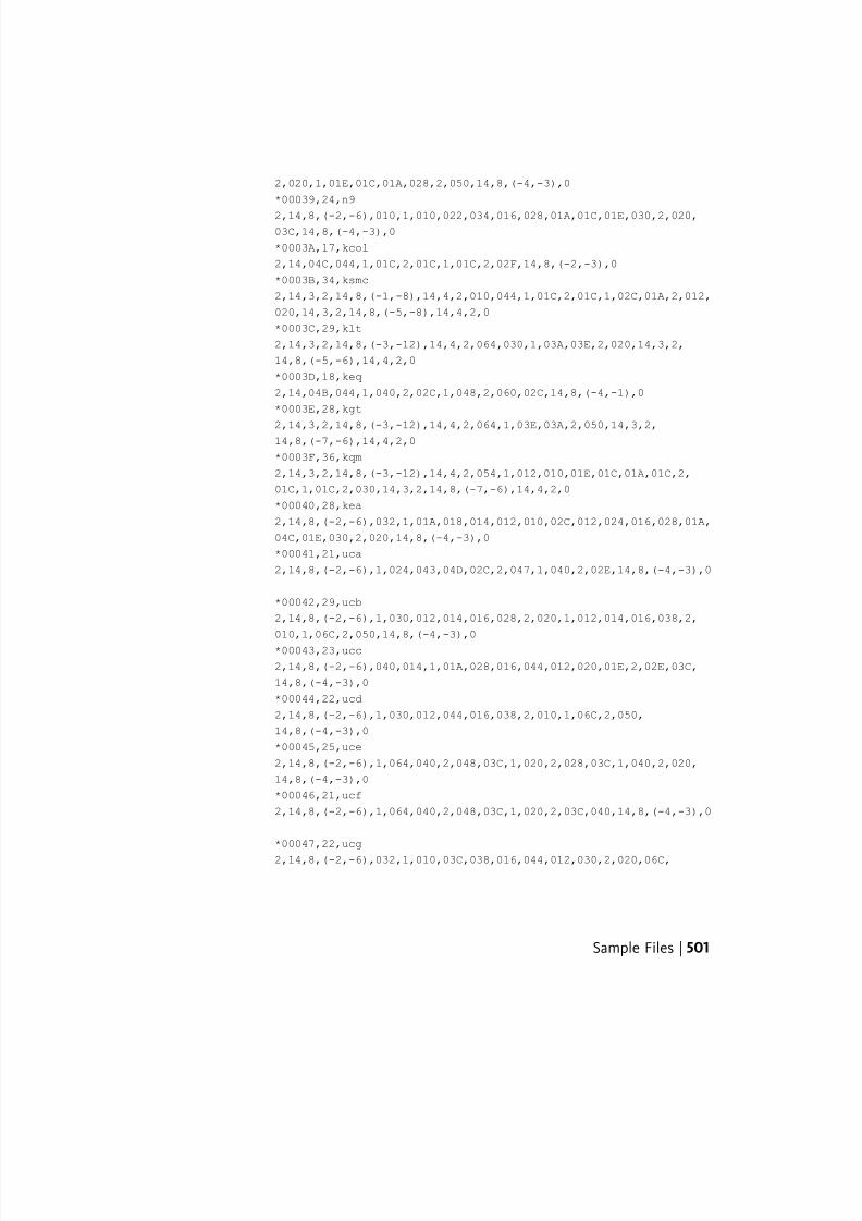
7/23/2019 Acad Customization
http://slidepdf.com/reader/full/acad-customization 509/553
2,020,1,01E,01C,01A,028,2,050,14,8,(-4,-3),0
*00039,24,n9
2,14,8,(-2,-6),010,1,010,022,034,016,028,01A,01C,01E,030,2,020,03C,14,8,(-4,-3),0
*0003A,17,kcol
2,14,04C,044,1,01C,2,01C,1,01C,2,02F,14,8,(-2,-3),0
*0003B,34,ksmc
2,14,3,2,14,8,(-1,-8),14,4,2,010,044,1,01C,2,01C,1,02C,01A,2,012,
020,14,3,2,14,8,(-5,-8),14,4,2,0
*0003C,29,klt
2,14,3,2,14,8,(-3,-12),14,4,2,064,030,1,03A,03E,2,020,14,3,2,
14,8,(-5,-6),14,4,2,0
*0003D,18,keq
2,14,04B,044,1,040,2,02C,1,048,2,060,02C,14,8,(-4,-1),0
*0003E,28,kgt
2,14,3,2,14,8,(-3,-12),14,4,2,064,1,03E,03A,2,050,14,3,2,14,8,(-7,-6),14,4,2,0
*0003F,36,kqm
2,14,3,2,14,8,(-3,-12),14,4,2,054,1,012,010,01E,01C,01A,01C,2,
01C,1,01C,2,030,14,3,2,14,8,(-7,-6),14,4,2,0
*00040,28,kea
2,14,8,(-2,-6),032,1,01A,018,014,012,010,02C,012,024,016,028,01A,
04C,01E,030,2,020,14,8,(-4,-3),0
*00041,21,uca
2,14,8,(-2,-6),1,024,043,04D,02C,2,047,1,040,2,02E,14,8,(-4,-3),0
*00042,29,ucb
2,14,8,(-2,-6),1,030,012,014,016,028,2,020,1,012,014,016,038,2,
010,1,06C,2,050,14,8,(-4,-3),0
*00043,23,ucc
2,14,8,(-2,-6),040,014,1,01A,028,016,044,012,020,01E,2,02E,03C,
14,8,(-4,-3),0
*00044,22,ucd
2,14,8,(-2,-6),1,030,012,044,016,038,2,010,1,06C,2,050,
14,8,(-4,-3),0
*00045,25,uce
2,14,8,(-2,-6),1,064,040,2,048,03C,1,020,2,028,03C,1,040,2,020,
14,8,(-4,-3),0
*00046,21,ucf
2,14,8,(-2,-6),1,064,040,2,048,03C,1,020,2,03C,040,14,8,(-4,-3),0
*00047,22,ucg
2,14,8,(-2,-6),032,1,010,03C,038,016,044,012,030,2,020,06C,
Sample Files | 501
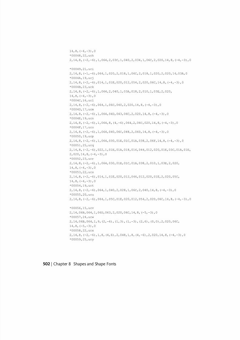
7/23/2019 Acad Customization
http://slidepdf.com/reader/full/acad-customization 510/553
14,8,(-4,-3),0
*00048,22,uch
2,14,8,(-2,-6),1,064,2,03C,1,040,2,034,1,06C,2,020,14,8,(-4,-3),0
*00049,21,uci
2,14,8,(-1,-6),064,1,020,2,018,1,06C,2,018,1,020,2,020,14,03A,0
*0004A,19,ucj
2,14,8,(-2,-6),014,1,01E,020,012,054,2,020,06C,14,8,(-4,-3),0
*0004B,23,uck
2,14,8,(-2,-6),1,064,2,040,1,03A,018,2,010,1,03E,2,020,
14,8,(-4,-3),0
*0004C,16,ucl
2,14,8,(-2,-6),064,1,06C,040,2,020,14,8,(-4,-3),0
*0004D,17,ucm
2,14,8,(-2,-6),1,064,04D,043,06C,2,020,14,8,(-4,-3),0
*0004E,19,ucn2,14,8,(-2,-6),1,064,8,(4,-6),064,2,06C,020,14,8,(-4,-3),0
*0004F,17,uco
2,14,8,(-2,-6),1,064,040,06C,048,2,060,14,8,(-4,-3),0
*00050,19,ucp
2,14,8,(-2,-6),1,064,030,01E,01C,01A,038,2,06F,14,8,(-4,-3),0
*00051,25,ucq
2,14,8,(-2,-6),022,1,01E,01A,018,016,044,012,020,01E,03C,01A,01E,
2,020,14,8,(-4,-3),0
*00052,23,ucr
2,14,8,(-2,-6),1,064,030,01E,01C,01A,038,2,010,1,03E,2,020,
14,8,(-4,-3),0
*00053,22,ucs
2,14,8,(-2,-6),014,1,01E,020,012,046,012,020,01E,2,020,05C,
14,8,(-4,-3),0
*00054,19,uct
2,14,8,(-2,-6),064,1,040,2,028,1,06C,2,040,14,8,(-4,-3),0
*00055,20,ucu
2,14,8,(-2,-6),064,1,05C,01E,020,012,054,2,020,06C,14,8,(-4,-3),0
*00056,15,ucv
2,14,06B,064,1,06D,063,2,020,06C,14,8,(-5,-3),0
*00057,24,ucw
2,14,06B,064,1,9,(2,-6),(1,3),(1,-3),(2,6),(0,0),2,020,06C,
14,8,(-5,-3),0
*00058,22,ucx
2,14,8,(-2,-6),1,8,(4,6),2,048,1,8,(4,-6),2,020,14,8,(-4,-3),0
*00059,25,ucy
502 | Chapter 8 Shapes and Shape Fonts
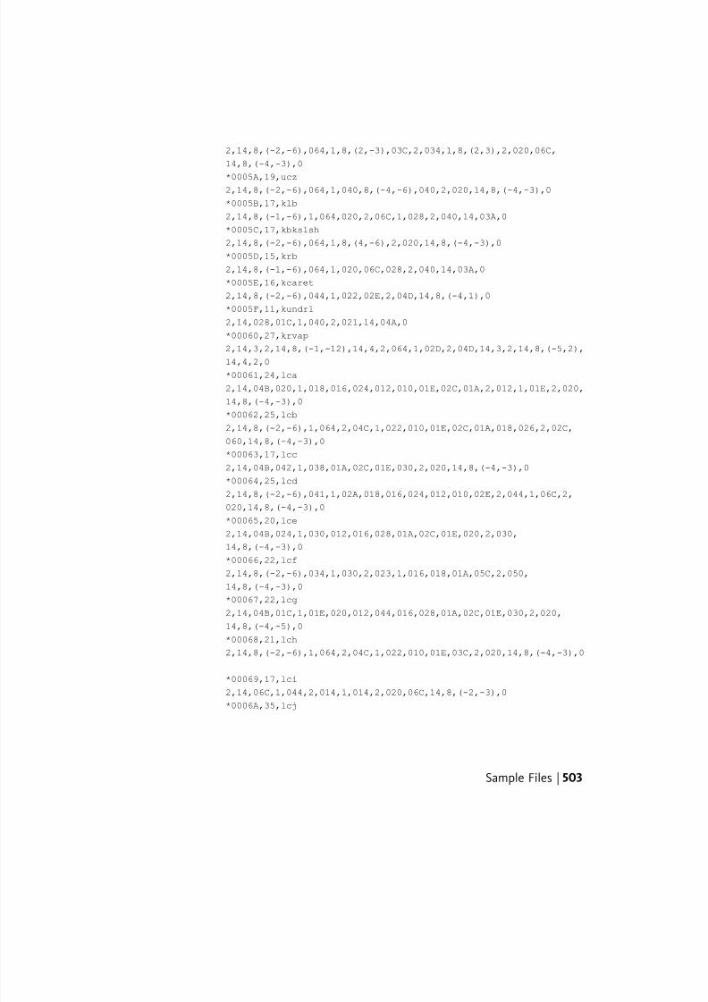
7/23/2019 Acad Customization
http://slidepdf.com/reader/full/acad-customization 511/553
2,14,8,(-2,-6),064,1,8,(2,-3),03C,2,034,1,8,(2,3),2,020,06C,
14,8,(-4,-3),0
*0005A,19,ucz2,14,8,(-2,-6),064,1,040,8,(-4,-6),040,2,020,14,8,(-4,-3),0
*0005B,17,klb
2,14,8,(-1,-6),1,064,020,2,06C,1,028,2,040,14,03A,0
*0005C,17,kbkslsh
2,14,8,(-2,-6),064,1,8,(4,-6),2,020,14,8,(-4,-3),0
*0005D,15,krb
2,14,8,(-1,-6),064,1,020,06C,028,2,040,14,03A,0
*0005E,16,kcaret
2,14,8,(-2,-6),044,1,022,02E,2,04D,14,8,(-4,1),0
*0005F,11,kundrl
2,14,028,01C,1,040,2,021,14,04A,0
*00060,27,krvap
2,14,3,2,14,8,(-1,-12),14,4,2,064,1,02D,2,04D,14,3,2,14,8,(-5,2),14,4,2,0
*00061,24,lca
2,14,04B,020,1,018,016,024,012,010,01E,02C,01A,2,012,1,01E,2,020,
14,8,(-4,-3),0
*00062,25,lcb
2,14,8,(-2,-6),1,064,2,04C,1,022,010,01E,02C,01A,018,026,2,02C,
060,14,8,(-4,-3),0
*00063,17,lcc
2,14,04B,042,1,038,01A,02C,01E,030,2,020,14,8,(-4,-3),0
*00064,25,lcd
2,14,8,(-2,-6),041,1,02A,018,016,024,012,010,02E,2,044,1,06C,2,
020,14,8,(-4,-3),0
*00065,20,lce
2,14,04B,024,1,030,012,016,028,01A,02C,01E,020,2,030,
14,8,(-4,-3),0
*00066,22,lcf
2,14,8,(-2,-6),034,1,030,2,023,1,016,018,01A,05C,2,050,
14,8,(-4,-3),0
*00067,22,lcg
2,14,04B,01C,1,01E,020,012,044,016,028,01A,02C,01E,030,2,020,
14,8,(-4,-5),0
*00068,21,lch
2,14,8,(-2,-6),1,064,2,04C,1,022,010,01E,03C,2,020,14,8,(-4,-3),0
*00069,17,lci
2,14,06C,1,044,2,014,1,014,2,020,06C,14,8,(-2,-3),0
*0006A,35,lcj
Sample Files | 503
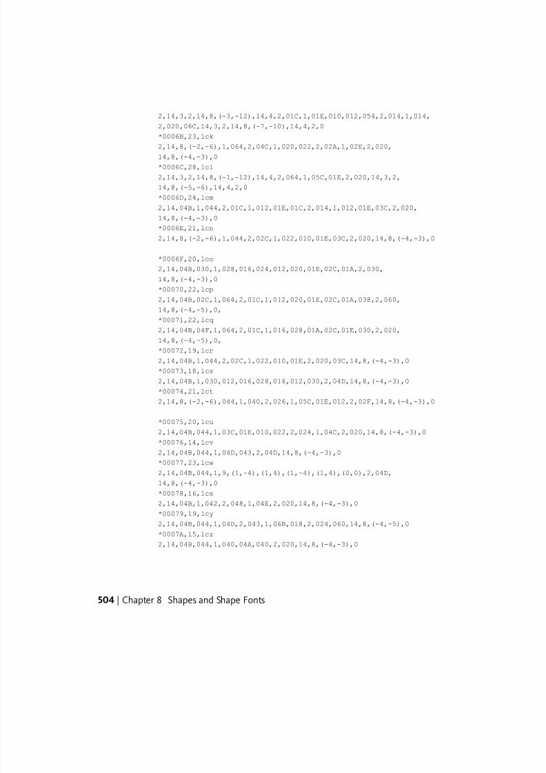
7/23/2019 Acad Customization
http://slidepdf.com/reader/full/acad-customization 512/553
2,14,3,2,14,8,(-3,-12),14,4,2,01C,1,01E,010,012,054,2,014,1,014,
2,020,06C,14,3,2,14,8,(-7,-10),14,4,2,0
*0006B,23,lck2,14,8,(-2,-6),1,064,2,04C,1,020,022,2,02A,1,02E,2,020,
14,8,(-4,-3),0
*0006C,28,lcl
2,14,3,2,14,8,(-1,-12),14,4,2,064,1,05C,01E,2,020,14,3,2,
14,8,(-5,-6),14,4,2,0
*0006D,24,lcm
2,14,04B,1,044,2,01C,1,012,01E,01C,2,014,1,012,01E,03C,2,020,
14,8,(-4,-3),0
*0006E,21,lcn
2,14,8,(-2,-6),1,044,2,02C,1,022,010,01E,03C,2,020,14,8,(-4,-3),0
*0006F,20,lco
2,14,04B,030,1,028,016,024,012,020,01E,02C,01A,2,030,14,8,(-4,-3),0
*00070,22,lcp
2,14,04B,02C,1,064,2,01C,1,012,020,01E,02C,01A,038,2,060,
14,8,(-4,-5),0,
*00071,22,lcq
2,14,04B,04F,1,064,2,01C,1,016,028,01A,02C,01E,030,2,020,
14,8,(-4,-5),0,
*00072,19,lcr
2,14,04B,1,044,2,02C,1,022,010,01E,2,020,03C,14,8,(-4,-3),0
*00073,18,lcs
2,14,04B,1,030,012,016,028,016,012,030,2,04D,14,8,(-4,-3),0
*00074,21,lct
2,14,8,(-2,-6),044,1,040,2,026,1,05C,01E,012,2,02F,14,8,(-4,-3),0
*00075,20,lcu
2,14,04B,044,1,03C,01E,010,022,2,024,1,04C,2,020,14,8,(-4,-3),0
*00076,14,lcv
2,14,04B,044,1,04D,043,2,04D,14,8,(-4,-3),0
*00077,23,lcw
2,14,04B,044,1,9,(1,-4),(1,4),(1,-4),(1,4),(0,0),2,04D,
14,8,(-4,-3),0
*00078,16,lcx
2,14,04B,1,042,2,048,1,04E,2,020,14,8,(-4,-3),0
*00079,19,lcy
2,14,04B,044,1,04D,2,043,1,06B,018,2,024,060,14,8,(-4,-5),0
*0007A,15,lcz
2,14,04B,044,1,040,04A,040,2,020,14,8,(-4,-3),0
504 | Chapter 8 Shapes and Shape Fonts
7/23/2019 Acad Customization
http://slidepdf.com/reader/full/acad-customization 513/553
*0007B,19,klbr
2,14,8,(-1,-6),064,020,1,01A,01C,01A,01E,01C,01E,2,020,14,03A,0
*0007C,13,kvbar2,14,06C,1,064,2,06C,020,14,8,(-2,-3),0
*0007D,18,krbr
2,14,8,(-1,-6),1,012,014,012,016,014,016,2,06C,040,14,03A,0
*0007E,15,ktlde
2,14,04B,034,1,012,02F,012,2,04D,14,8,(-4,-2),0
*00080,4,keuroRef
7,020AC,0
*000A0,7,NoBrkSpc
2,060,14,8,(-6,-8),0
*000A1,18,kiexc
2,14,06C,1,044,2,014,1,014,2,8,(2,-6),14,8,(-2,-3),0
*000A2,23,kcent
2,14,8,(-2,-5),01E,1,8,(2,6),2,01E,1,038,01A,02C,01E,030,2,020,14,04A,0,
*000A3,23,kpound
2,14,8,(-2,-6),040,1,048,012,044,012,01E,2,02B,1,028,2,06F,
14,8,(-4,-3),0
*000A5,34,kyen
2,14,8,(-2,-6),064,1,8,(2,-3),03C,2,025,1,020,2,027,1,020,2,018,
1,8,(2,3),2,8,(2,-6),14,8,(-4,-3),0
*000A7,45,kpar
2,14,3,2,14,8,(-3,-12),14,4,2,014,1,01E,010,012,016,018,016,012,
2,021,1,016,018,01A,01E,010,01E,01A,2,8,(3,-2),14,3,2,
14,8,(-7,-6),14,4,2,0
*000AA,36,lcau
2,14,8,(-1,-6),2,3,2,8,3,9,1,01A,018,016,024,012,010,01E,02C,01E,
2,049,1,040,2,4,2,8,2,-3,14,8,(-3,1),0
*000AB,21,kfrew
2,14,8,(-2,-5),021,1,026,022,2,020,1,02A,02E,2,02F,14,8,(-4,-2),0
*000B0,19,kdeg
2,14,8,(-1,-6),054,1,012,01E,01A,016,2,05C,040,14,8,(-3,2),0
*000B1,23,kpls-min
2,14,8,(-2,-6),014,1,040,2,027,1,044,2,02A,1,040,2,04D,
14,8,(-4,-2),0
*000B5,24,kmicro
2,14,04B,02C,1,8,(1,6),1,03C,01E,010,023,2,024,1,04C,2,020,
14,8,(-4,-5),0
*000BA,35,lcou
2,14,8,(-1,-6),3,2,2,8,3,12,1,028,01A,02C,01E,020,012,024,016,2,
Sample Files | 505
7/23/2019 Acad Customization
http://slidepdf.com/reader/full/acad-customization 514/553
06B,1,040,2,4,2,8,2,-3,14,8,(-3,1),0
*000BB,22,kffrw
2,14,8,(-2,-5),014,1,022,026,2,020,1,02E,02A,2,040,01C,14,8,(-4,-2),0
*000BC,41,kquart
2,3,2,14,8,(-5,-12),1,8,(10,12),2,8,(-8,-6),1,064,01A,2,05C,1,
020,2,8,(6,-4),1,048,8,(3,4),06C,2,060,14,8,(-9,-6),4,2,0
*000BD,45,khalf
2,3,2,14,8,(-5,-12),1,8,(10,12),2,8,(-8,-6),1,064,01A,2,05C,1,
020,2,8,(3,-1),1,012,020,01E,01C,01A,028,01A,02C,040,2,040,
14,8,(-9,-6),4,2,0
*000BF,32,kiqm
2,3,2,14,8,(-3,-12),8,(6,2),1,02A,028,026,024,022,024,2,024,1,
024,2,8,(8,-12),14,8,(-7,-6),4,2,0
*000C0,31,uc^
2,14,8,(-2,-6),1,024,022,02E,02C,2,8,(-4,1),1,040,2,8,(-2,4),1,027,2,8,(6,-6),14,8,(-4,-3),0
*000C1,31,uc^
2,14,8,(-2,-6),1,024,022,02E,02C,2,8,(-4,1),1,040,2,8,(-2,4),1,
021,2,8,(2,-6),14,8,(-4,-3),0
*000C2,32,uc^
2,14,8,(-2,-6),1,024,022,02E,02C,2,8,(-4,1),1,040,2,8,(-4,3),1,
022,02E,2,8,(2,-4),14,8,(-4,-3),0
*000C3,33,uc^
2,14,8,(-2,-6),1,024,022,02E,02C,2,8,(-4,1),1,040,2,8,(-4,4),1,
012,02F,012,2,8,(2,-6),14,8,(-4,-3),0
*000C4,32,uc„
2,14,8,(-2,-6),1,024,043,2,029,1,014,2,040,1,01C,2,027,1,04D,02C,
2,047,1,040,2,02E,14,8,(-4,-3),0
*000C5,25,uc^
2,14,8,(-2,-6),1,024,032,016,01A,03E,02C,2,8,(-4,1),1,040,2,02F,
14,8,(-4,-3),0
*000C6,33,uc^
2,14,8,(-2,-6),1,034,8,(2,3),020,2,8,(-2,-3),1,020,2,03C,1,028,
064,2,04B,1,020,2,04F,14,8,(-4,-3),0
*000C7,29,uc‡
2,14,8,(-2,-6),02E,1,010,014,018,014,2,021,1,01A,028,016,044,012,
020,01E,2,02E,03C,14,8,(-4,-5),0
*000C8,28,uc^
2,14,8,(-2,-6),1,044,040,2,016,1,027,2,04C,018,1,020,2,02A,1,040,
2,020,14,8,(-4,-3),0
*000C9,28,uc^
2,14,8,(-2,-6),1,044,040,2,025,1,029,2,03C,018,1,020,2,02A,1,040,
506 | Chapter 8 Shapes and Shape Fonts
7/23/2019 Acad Customization
http://slidepdf.com/reader/full/acad-customization 515/553
2,020,14,8,(-4,-3),0
*000CA,29,uc^
2,14,8,(-2,-6),1,044,040,2,016,1,016,01A,2,03C,018,1,020,2,02A,1,040,2,020,14,8,(-4,-3),0
*000CB,32,uc^
2,14,8,(-2,-6),1,044,040,2,016,1,014,2,028,1,01C,2,03C,018,1,020,
2,02A,1,040,2,020,14,8,(-4,-3),0
*000CC,25,uc^
2,14,8,(-1,-6),044,1,020,2,014,1,027,2,02D,1,04C,2,018,1,020,2,
020,14,03A,0
*000CD,25,uc^
2,14,8,(-1,-6),044,1,020,2,024,1,029,2,01E,1,04C,2,018,1,020,2,
020,14,03A,0
*000CE,26,uc^
2,14,8,(-1,-6),044,1,020,2,014,1,016,01A,2,01E,1,04C,2,018,1,020,2,020,14,03A,0
*000CF,29,uc^
2,14,8,(-1,-6),044,1,020,2,014,1,014,2,028,1,01C,2,01E,1,04C,2,
018,1,020,2,020,14,03A,0
*000D0,25,uc
2,14,8,(-2,-6),1,064,030,01E,04C,01A,038,2,024,015,1,020,2,01D,
04F,14,8,(-4,-3),0
*000D1,25,uc
2,14,8,(-2,-6),1,044,04E,044,2,048,014,1,012,02F,012,2,8,(2,-6),
14,8,(-4,-3),0
*000D2,25,uc^
2,14,8,(-2,-6),1,044,040,2,016,1,027,2,02C,030,1,04C,048,2,060,
14,8,(-4,-3),0
*000D3,25,uc^
2,14,8,(-2,-6),1,044,040,2,025,1,029,2,01C,030,1,04C,048,2,060,
14,8,(-4,-3),0
*000D4,26,uc^
2,14,8,(-2,-6),1,044,040,2,016,1,016,01A,2,01C,030,1,04C,048,2,
060,14,8,(-4,-3),0
*000D5,27,uc^
2,14,8,(-2,-6),1,044,040,2,024,1,01A,027,01A,2,01C,040,1,04C,048,
2,060,14,8,(-4,-3),0
*000D6,31,uc^
2,14,8,(-2,-6),1,044,2,012,1,014,2,02B,1,040,2,016,1,014,2,02D,1,
04C,048,2,060,14,8,(-4,-3),0
*000D8,29,ucd”
Sample Files | 507
7/23/2019 Acad Customization
http://slidepdf.com/reader/full/acad-customization 516/553
2,14,8,(-2,-6),1,8,(4,6),2,018,1,01E,04C,01A,028,016,044,012,020,
2,8,(3,-6),14,8,(-4,-3),0
*000D9,24,uc^2,14,8,(-2,-6),064,1,05C,01E,020,012,054,2,01A,1,027,2,050,06C,
14,8,(-4,-3),0
*000DA,24,uc^
2,14,8,(-2,-6),064,1,05C,01E,020,012,054,2,018,1,029,2,050,05C,
14,8,(-4,-3),0
*000DB,25,uc^
2,14,8,(-2,-6),064,1,05C,01E,020,012,054,2,01A,1,016,01A,2,050,
05C,14,8,(-4,-3),0
*000DC,27,uc^
2,14,8,(-2,-6),064,1,05C,01E,020,012,054,2,01A,1,014,2,028,1,01C,
2,05E,14,8,(-4,-3),0
*000DD,25,uc^
2,14,8,(-2,-6),044,1,02E,02C,2,024,1,022,2,025,1,029,2,050,05C,14,8,(-4,-3),0
*000DE,27,lc
2,14,8,(-2,-6),02C,1,084,2,03C,1,012,020,01E,02C,01A,028,016,2,
8,(6,-1),14,8,(-4,-5),0
*000DF,24,kgers
2,14,8,(-2,-6),1,012,044,012,010,01E,01C,01A,01E,01C,01A,018,2,
040,14,8,(-4,-3),0
*000E0,39,lc…
2,14,8,(-2,-6),020,1,018,016,024,012,010,01E,02C,01A,2,012,1,01E,
2,2,3,2,8,(-3,10),1,047,2,8,(11,-12),4,2,14,8,(-4,-3),0
*000E1,39,lc
2,14,8,(-2,-6),020,1,018,016,024,012,010,01E,02C,01A,2,012,1,01E,
2,2,3,2,8,(-3,12),1,049,2,8,(11,-10),4,2,14,8,(-4,-3),0
*000E2,40,lcƒ
2,14,8,(-2,-6),020,1,018,016,024,012,010,01E,02C,01A,2,012,1,01E,
2,2,3,2,8,(-3,10),1,026,02A,2,8,(11,-10),4,2,14,8,(-4,-3),0
*000E3,40,lcƒ
2,14,8,(-2,-6),020,1,018,016,024,012,010,01E,02C,01A,2,012,1,01E,
2,3,2,8,(-7,10),1,012,02F,012,2,8,(7,-11),4,2,14,8,(-4,-3),0
*000E4,37,lc„
2,14,8,(-2,-6),020,1,018,016,024,2,034,1,01C,2,030,1,014,2,03A,1,
012,010,01E,02C,01A,2,012,1,01E,2,020,14,8,(-4,-3),0
*000E5,38,lc†
2,14,8,(-2,-6),3,2,8,(3,8),1,022,026,02A,02E,2,8,(3,-6),4,2,1,
01A,018,016,024,012,010,01E,02C,01E,2,020,14,8,(-4,-3),0
*000E6,30,lc
508 | Chapter 8 Shapes and Shape Fonts
7/23/2019 Acad Customization
http://slidepdf.com/reader/full/acad-customization 517/553
2,14,04B,021,1,01A,016,024,012,01E,03C,2,034,1,012,01E,01C,028,2,
01C,1,01E,010,2,020,14,8,(-4,-3),0
*000E7,24,lc‡2,14,04B,042,1,038,01A,02C,01E,030,2,028,1,01C,010,01C,018,2,041,
14,8,(-4,-5),0
*000E8,27,lcŠ
2,14,8,(-2,-6),024,1,030,012,016,028,01A,02C,01E,020,2,054,1,027,
2,050,06C,14,8,(-4,-3),0
*000E9,26,lc‚
2,14,8,(-2,-6),024,1,030,012,016,028,01A,02C,01E,020,2,064,1,029,
2,05E,14,8,(-4,-3),0
*000EA,27,lcˆ
2,14,8,(-2,-6),024,1,030,012,016,028,01A,02C,01E,020,2,054,1,016,
01A,2,05E,14,8,(-4,-3),0
*000EB,31,lc‰2,14,8,(-2,-6),024,1,030,012,016,028,01A,02C,01E,020,2,064,010,1,
01C,2,048,1,014,2,06E,14,8,(-4,-3),0
*000EC,18,lc_
2,14,8,(-1,-6),010,1,044,2,025,1,02F,2,020,05C,14,03A,0
*000ED,18,lc
2,14,8,(-1,-6),010,1,044,2,016,1,021,2,020,06C,14,03A,0
*000EE,19,lcŒ
2,14,8,(-1,-6),010,1,044,2,016,1,012,01E,2,020,05C,14,03A,0
*000EF,22,lc‹
2,14,8,(-1,-6),010,1,044,2,016,1,014,2,020,1,01C,2,020,05C,
14,03A,0
*000F0,30,lc
2,14,8,(-2,-6),8,(3,4),1,028,01A,02C,01E,020,012,024,036,2,01C,1,
021,2,8,(3,-6),14,8,(-4,-3),0
*000F1,27,lc
2,14,8,(-2,-6),1,044,2,014,1,012,02F,012,2,04A,1,022,010,01E,03C,
2,020,14,8,(-4,-3),0
*000F2,27,lc•
2,14,8,(-2,-6),030,1,028,016,024,012,020,01E,02C,01A,2,054,1,027,
2,050,06C,14,8,(-4,-3),0
*000F3,26,lc
2,14,8,(-2,-6),030,1,028,016,024,012,020,01E,02C,01A,2,064,1,029,
2,05E,14,8,(-4,-3),0
*000F4,27,lc“
2,14,8,(-2,-6),030,1,028,016,024,012,020,01E,02C,01A,2,054,1,016,
01A,2,05E,14,8,(-4,-3),0
Sample Files | 509
7/23/2019 Acad Customization
http://slidepdf.com/reader/full/acad-customization 518/553
*000F5,32,lc^
2,14,8,(-2,-6),030,1,028,016,024,012,020,01E,02C,01A,2,8,(-3,5),
1,012,02F,012,2,8,(2,-6),14,8,(-4,-3),0*000F6,35,lc”
2,14,8,(-2,-6),030,1,028,016,024,2,034,1,01C,2,040,1,014,2,
8,(-4,-3),1,012,020,01E,02C,01A,2,030,14,8,(-4,-3),0
*000F7,23,kto
2,14,8,(-2,-5),021,1,014,2,021,1,048,2,022,1,01C,2,04E,
14,8,(-4,-2),0
*000F8,24,lcd”
2,14,04B,010,1,020,012,024,016,028,01A,02C,01E,2,018,1,042,2,04D,
14,8,(-4,-3),0
*000F9,27,lc—
2,14,8,(-2,-6),044,1,03C,01E,010,022,2,038,044,1,02F,2,01E,1,04C,
2,020,14,8,(-4,-3),0
*000FA,26,lc2,14,8,(-2,-6),044,1,03C,01E,010,022,2,036,1,021,2,02D,1,04C,2,
020,14,8,(-4,-3),0
*000FB,27,lc-
2,14,8,(-2,-6),044,1,03C,01E,010,022,2,036,1,012,01E,2,01E,1,04C,
2,020,14,8,(-4,-3),0
*000FC,32,lc_
2,14,8,(-2,-6),064,010,1,01C,2,01A,1,03C,01E,010,022,2,044,018,1,
01C,2,01E,1,04C,2,020,14,8,(-4,-3),0
*000FD,27,lc^
2,14,8,(-2,-6),044,1,04D,2,8,(-1,5),1,021,2,02D,1,06B,018,2,024,
060,14,8,(-4,-3),0
*000FE,25,uc
2,14,8,(-2,-6),1,064,2,01E,019,1,030,01E,01C,01A,038,2,01F,01C,
050,14,8,(-4,-3),0
*000FF,30,lc˜
2,14,8,(-2,-6),044,1,04D,2,054,018,1,014,2,020,1,01C,2,01E,1,06B,
018,2,024,060,14,8,(-4,-5),0
*00104,26,c164
2,14,8,(-2,-6),1,024,043,04D,02C,2,047,1,040,2,02C,1,01A,01E,2,
022,14,8,(-4,-3),0
*00105,30,c165
2,14,04B,020,1,018,016,024,012,010,01E,02C,01A,2,012,1,01E,3,2,
01A,01E,4,2,2,021,14,8,(-4,-3),0
*00106,28,c143
2,14,8,(-2,-6),040,014,1,01A,028,016,044,012,020,01E,2,038,024,1,
021,2,08C,030,14,8,(-4,-3),0
*00107,30,c134
510 | Chapter 8 Shapes and Shape Fonts
7/23/2019 Acad Customization
http://slidepdf.com/reader/full/acad-customization 519/553
2,14,04B,042,1,038,01A,02C,01E,030,2,3,2,8,(-5,10),1,021,2,029,
8,(9,-10),4,2,14,8,(-4,-3),0
*0010C,31,c1722,14,8,(-2,-8),040,014,1,01A,028,016,044,012,020,01E,2,026,1,012,
2,01A,1,016,2,050,08C,14,8,(-4,-3),0
*0010D,29,c159
2,14,8,(-2,-6),042,1,038,01A,02C,01E,030,2,028,054,1,012,2,01A,1,
016,2,050,06C,14,8,(-4,-3),0
*0010E,32,c210
2,14,8,(-2,-8),1,030,012,044,016,038,2,010,1,06C,2,010,074,1,012,
2,01A,1,016,2,050,08C,14,8,(-4,-3),0
*0010F,31,c212
2,14,8,(-2,-6),041,1,02A,018,016,024,012,010,02E,2,044,1,06C,2,
020,064,1,01A,2,010,05C,14,8,(-4,-3),0
*00118,28,c168
2,14,8,(-2,-6),1,064,040,2,048,03C,1,020,2,028,03C,1,040,1,01A,01E,2,022,14,8,(-4,-3),0
*00119,27,c169
2,14,04B,024,1,030,012,016,028,01A,02C,01E,020,3,2,01A,01E,4,2,2,
014,030,14,8,(-4,-3),0
*0011A,35,c183
2,14,8,(-2,-8),1,064,040,2,048,03C,1,020,2,028,03C,1,040,2,028,
074,1,012,2,01A,1,016,2,050,08C,14,8,(-4,-3),0
*0011B,32,c216
2,14,8,(-2,-6),024,1,030,012,016,028,01A,02C,01E,020,2,018,054,1,
012,2,01A,1,016,2,050,06C,14,8,(-4,-3),0
*00141,29,c157
2,14,8,(-2,-6),064,1,06C,040,2,048,034,1,3,2,8,(4,5),2,8,(8,-11),
4,2,14,8,(-4,-3),0
*00142,47,c136
2,14,3,2,14,8,(-1,-12),14,4,2,064,3,2,010,4,2,1,05C,01E,2,3,2,
8,(-3,5),1,8,(3,4),2,8,(4,-9),4,2,14,3,2,14,8,(-5,-6),14,4,2,0
*00143,24,c227
2,14,8,(-2,-6),1,064,8,(4,-6),064,2,038,014,1,021,2,08C,030,
14,8,(-4,-3),0
*00144,42,c228
2,14,3,2,14,8,(-3,-8),14,4,2,1,044,2,01C,1,012,010,01E,03C,2,
8,(-2,5),1,011,2,019,8,(4,-5),14,3,2,14,8,(-7,-6),14,4,2,0
*00147,27,c213
2,14,8,(-2,-8),1,064,8,(4,-6),064,2,027,1,012,2,01A,1,016,2,050,
08C,14,8,(-4,-3),0
*00148,29,c229
2,14,8,(-2,-6),1,044,2,01C,1,012,010,01E,03C,2,018,054,1,012,2,
Sample Files | 511
7/23/2019 Acad Customization
http://slidepdf.com/reader/full/acad-customization 520/553
01A,1,016,2,040,06C,14,03A,0
*00150,27,c138
2,14,8,(-2,-6),1,064,040,06C,048,2,074,010,1,03C,2,020,1,034,2,07C,030,14,8,(-4,-3),0
*00151,29,c139
2,14,04B,030,1,028,016,024,012,020,01E,02C,01A,2,074,1,02C,2,028,
1,024,2,07C,050,14,8,(-4,-3),0
*00158,33,c252
2,14,8,(-2,-8),1,064,030,01E,01C,01A,038,2,010,1,03E,2,028,074,1,
012,2,01A,1,016,2,050,08C,14,8,(-4,-3),0
*00159,29,c253
2,14,8,(-2,-6),1,044,2,02C,1,022,010,01E,2,026,1,012,2,01A,1,016,
2,050,06C,14,8,(-4,-3),0
*0015A,27,c151
2,14,8,(-2,-6),014,1,01E,020,012,046,012,020,01E,2,024,038,1,021,2,08C,030,14,8,(-4,-3),0
*0015B,31,c152
2,14,04B,1,030,012,016,028,016,012,030,2,3,2,8,(-5,2),1,021,2,
029,8,(9,-10),4,2,14,8,(-4,-3),0
*00160,30,c230
2,14,8,(-2,-8),014,1,01E,020,012,046,012,020,01E,2,026,1,012,2,
01A,1,016,2,050,08C,14,8,(-4,-3),0
*00161,29,c231
2,14,8,(-2,-6),1,030,012,016,028,016,012,030,2,027,1,012,2,01A,1,
016,2,050,06C,14,8,(-4,-3),0
*00164,28,c155
2,14,8,(-2,-8),064,1,040,2,028,1,06C,2,074,1,012,2,01A,1,016,2,
050,08C,14,8,(-4,-3),0
*00165,26,c156
2,14,8,(-2,-6),044,1,040,2,026,1,05C,01E,012,2,054,1,01A,2,030,
05C,14,8,(-4,-3),0
*0016E,27,c222
2,14,8,(-2,-9),064,1,05C,01E,020,012,054,2,027,1,012,016,01A,01E,
2,040,07C,14,8,(-4,-3),0
*0016F,31,c133
2,14,8,(-2,-7),044,1,03C,01E,010,022,2,024,1,04C,2,028,054,1,012,
016,01A,01E,2,040,05C,14,8,(-4,-3),0
*00170,28,c235
2,14,8,(-2,-6),064,1,05C,01E,020,012,054,2,016,1,03C,2,028,1,034,
2,07C,050,14,8,(-4,-3),0
*00171,30,uue
512 | Chapter 8 Shapes and Shape Fonts
7/23/2019 Acad Customization
http://slidepdf.com/reader/full/acad-customization 521/553
2,14,04B,044,1,03C,01E,010,022,2,024,1,04C,2,074,018,1,02C,2,028,
1,024,2,07C,050,14,8,(-4,-3),0
*00179,25,c1412,14,8,(-2,-6),064,1,040,8,(-4,-6),040,2,038,074,1,021,2,08C,030,
14,8,(-4,-3),0
*0017A,28,c171
2,14,04B,044,1,040,04A,040,2,3,2,8,(-5,10),1,021,2,029,8,(9,-10),
4,2,14,8,(-4,-3),0
*0017B,32,c189
2,14,8,(-2,-6),064,1,040,8,(-4,-6),040,2,084,028,1,3,4,01A,01E,
012,016,4,4,2,040,08C,14,8,(-4,-3),0
*0017C,34,c190
2,14,04B,044,1,040,04A,040,2,3,2,8,(-4,11),3,4,1,01A,01E,012,016,
4,4,2,8,(8,-11),4,2,14,8,(-4,-3),0
*0017D,29,c166
2,14,8,(-2,-8),064,1,040,8,(-4,-6),040,2,028,074,1,012,2,01A,1,016,2,050,08C,14,8,(-4,-3),0
*0017E,27,c167
2,14,8,(-2,-6),044,1,040,04A,040,2,028,054,1,012,2,01A,1,016,2,
050,06C,14,8,(-4,-3),0
*00410,21,ucra
2,14,8,(-2,-6),1,024,043,04D,02C,2,047,1,040,2,02E,14,8,(-4,-3),0
*00411,24,ucrb
2,14,8,(-2,-6),1,064,030,01C,014,038,03C,030,01E,01C,01A,038,2,
060,14,8,(-4,-3),0
*00412,29,ucrv
2,14,8,(-2,-6),1,030,012,014,016,028,2,020,1,012,014,016,038,2,
010,1,06C,2,050,14,8,(-4,-3),0
*00413,17,ucrg
2,14,8,(-2,-6),1,064,040,01C,2,05C,020,14,8,(-4,-3),0
*00414,23,ucrd
2,14,8,(-2,-6),01C,1,014,050,064,028,04B,02C,050,01C,2,014,020,
14,8,(-6,-3),0
*00415,25,ucre
2,14,8,(-2,-6),1,064,040,2,048,03C,1,020,2,028,03C,1,040,2,020,
14,8,(-4,-3),0
*00416,22,ucr!
2,14,8,(-2,-6),062,2,038,1,06C,2,038,064,1,06E,2,020,
14,8,(-6,-3),0
*00417,27,ucr!
2,14,8,(-2,-6),014,1,01E,020,012,014,016,018,010,012,014,016,028,
01A,2,060,05C,14,8,(-4,-3),0
Sample Files | 513
7/23/2019 Acad Customization
http://slidepdf.com/reader/full/acad-customization 522/553
*00418,20,ucri
2,14,8,(-2,-6),1,042,04C,064,2,048,1,06C,2,060,14,8,(-4,-3),0
*00419,24,ucrikr2,14,8,(-2,-6),1,042,04C,064,2,018,1,028,2,018,1,06C,2,060,
14,8,(-4,-3),0
*0041A,23,ucrk
2,14,8,(-2,-6),1,064,2,040,1,03A,018,2,010,1,03E,2,020,
14,8,(-4,-3),0
*0041B,17,ukrl
2,14,8,(-2,-6),1,010,063,010,06C,2,020,14,8,(-5,-3),0
*0041C,17,ucrm
2,14,8,(-2,-6),1,064,04D,043,06C,2,020,14,8,(-4,-3),0
*0041D,22,ucrn
2,14,8,(-2,-6),1,064,2,03C,1,040,2,034,1,06C,2,020,14,8,(-4,-3),0
*0041E,23,ucro2,14,8,(-2,-6),014,1,044,012,020,01E,04C,01A,028,016,2,060,01C,
14,8,(-4,-3),0
*0041F,16,ucrp
2,14,8,(-2,-6),1,064,040,06C,2,020,14,8,(-4,-3),0
*00420,19,ucrr
2,14,8,(-2,-6),1,064,030,01E,01C,01A,038,2,06F,14,8,(-4,-3),0
*00421,23,ucrs
2,14,8,(-2,-6),040,014,1,01A,028,016,044,012,020,01E,2,02E,03C,
14,8,(-4,-3),0
*00422,19,ucrt
2,14,8,(-2,-6),064,1,040,2,028,1,06C,2,040,14,8,(-4,-3),0
*00423,23,ucru
2,14,8,(-2,-6),014,1,01E,020,012,054,04C,038,016,034,2,060,06C,
14,8,(-4,-3),0
*00424,25,ucrf
2,14,8,(-2,-6),020,1,064,018,01A,02C,01E,020,012,024,016,018,2,
040,06C,14,8,(-4,-3),0
*00425,22,ucrx
2,14,8,(-2,-6),1,8,(4,6),2,048,1,8,(4,-6),2,020,14,8,(-4,-3),0
*00426,21,ucr!
2,14,8,(-2,-6),1,064,06C,040,064,06C,010,01C,2,014,020,
14,8,(-5,-3),0
*00427,19,ucrch
2,14,8,(-2,-6),064,1,03C,01E,030,044,06C,2,020,14,8,(-4,-3),0
*00428,21,ucrsh
2,14,8,(-2,-6),1,064,06C,030,044,04C,030,064,06C,2,020,
14,8,(-6,-3),0
514 | Chapter 8 Shapes and Shape Fonts
7/23/2019 Acad Customization
http://slidepdf.com/reader/full/acad-customization 523/553
*00429,24,ucr!
2,14,8,(-2,-6),1,064,06C,030,044,04C,030,064,06C,010,01C,014,2,
020,14,8,(-7,-3),0*0042A,23,ucr'
2,14,8,(-2,-6),054,1,014,010,06C,030,012,014,016,038,2,060,03C,
14,8,(-5,-3),0
*0042B,24,ucrs
2,14,8,(-2,-6),1,030,012,014,016,038,03C,064,2,050,1,06C,2,020,
14,8,(-5,-3),0
*0042C,21,ucr]
2,14,8,(-2,-6),1,030,012,014,016,038,03C,064,2,060,06C,
14,8,(-4,-3),0
*0042D,25,ucr'
2,14,8,(-2,-6),014,1,01E,020,012,024,028,020,024,016,028,01A,2,
060,05C,14,8,(-4,-3),00,
*0042E,26,ucr!2,14,8,(-2,-6),1,064,03C,010,024,012,010,01E,04C,01A,018,016,024,
2,050,03C,14,8,(-4,-3),0
*0042F,22,ucrya
2,14,8,(-2,-6),1,022,020,044,038,01A,02C,01E,030,02C,2,020,
14,8,(-4,-3),0
*00430,25,lcra
2,14,8,(-2,-6),014,1,024,012,020,01E,014,04C,014,01A,028,016,2,
060,01C,14,8,(-4,-3),0
*00431,22,lcrb
2,14,8,(-2,-6),044,030,1,038,04C,030,012,016,038,2,02C,060,
14,8,(-4,-3),0
*00432,24,lcrv
2,14,8,(-2,-6),1,044,020,10,(1,-36),028,030,10,(1,-36),038,2,060,
14,8,(-4,-3),0
*00433,16,lcrg
2,14,8,(-2,-6),1,044,030,2,04C,020,14,8,(-3,-3),0
*00434,24,lcrd
2,14,8,(-2,-6),01C,1,014,010,034,012,010,04C,028,030,01C,2,014,
020,14,8,(-4,-3),00,
*00435,20,lcre
2,14,04B,024,1,030,012,016,028,01A,02C,01E,020,2,030,
14,8,(-4,-3),0
*00436,23,lcrg
2,14,8,(-2,-6),1,042,2,048,1,04E,2,028,1,044,2,040,04C,
14,8,(-4,-3),0
*00437,25,lcrz
2,14,8,(-2,-6),034,1,012,020,01E,01A,018,010,01E,01A,028,016,2,
Sample Files | 515
7/23/2019 Acad Customization
http://slidepdf.com/reader/full/acad-customization 524/553
060,01C,14,8,(-4,-3),0
*00438,17,lcri
2,14,8,(-2,-6),044,1,04C,042,04C,2,020,14,8,(-4,-3),0*00439,23,lcrii
2,14,8,(-2,-6),044,1,04C,042,04C,2,044,018,1,028,2,050,04C,
14,8,(-4,-3),0
*0043A,19,lcrk
2,14,8,(-2,-6),1,044,02C,020,022,02A,02E,2,020,14,8,(-4,-3),0
*0043B,16,lcrl
2,14,8,(-2,-6),1,043,020,04C,2,020,14,8,(-4,-3),0
*0043C,17,lcrm
2,14,8,(-2,-6),1,044,02E,022,04C,2,020,14,8,(-4,-3),0
*0043D,18,lcrn
2,14,8,(-2,-6),1,044,02C,040,024,04C,2,020,14,8,(-4,-3),0
*0043E,25,lcro
2,14,04B,14,8,(0,-2),014,1,024,012,020,01E,02C,01A,028,016,2,060,01C,14,8,(-4,-3),0
*0043F,16,lcrp
2,14,8,(-2,-6),1,044,040,04C,2,020,14,8,(-4,-3),0
*00440,20,lcrr
2,14,8,(-2,-6),1,044,030,01E,01C,01A,038,2,060,01C,14,8,(-4,-3),0
*00441,23,lcrs
2,14,8,(-2,-6),040,014,1,01A,028,016,024,012,020,01E,2,020,03C,
14,8,(-4,-3),0
*00442,18,lcrt
2,14,8,(-2,-6),020,1,044,028,040,2,020,04C,14,8,(-4,-3),0
*00443,22,lcru
2,14,8,(-2,-6),014,1,01E,020,012,034,02C,028,026,2,060,04C,
14,8,(-4,-3),0
*00444,25,lcrf
2,14,8,(-2,-6),020,1,044,018,01A,01C,01E,020,012,014,016,018,2,
040,04C,14,8,(-4,-3),0
*00445,20,lcrh
2,14,04B,14,8,(0,-2),1,042,2,048,1,04E,2,020,14,8,(-4,-3),0
*00446,21,lcrc
2,14,8,(-2,-6),044,1,04C,030,044,04C,010,01C,2,014,020,
14,8,(-4,-3),0
*00447,18,lcrch
2,14,8,(-2,-6),044,1,03C,030,034,04C,2,020,14,8,(-3,-3),0
*00448,21,lcrsh
2,14,8,(-2,-6),1,044,04C,020,024,02C,020,044,2,04C,020,
14,8,(-4,-3),0
516 | Chapter 8 Shapes and Shape Fonts
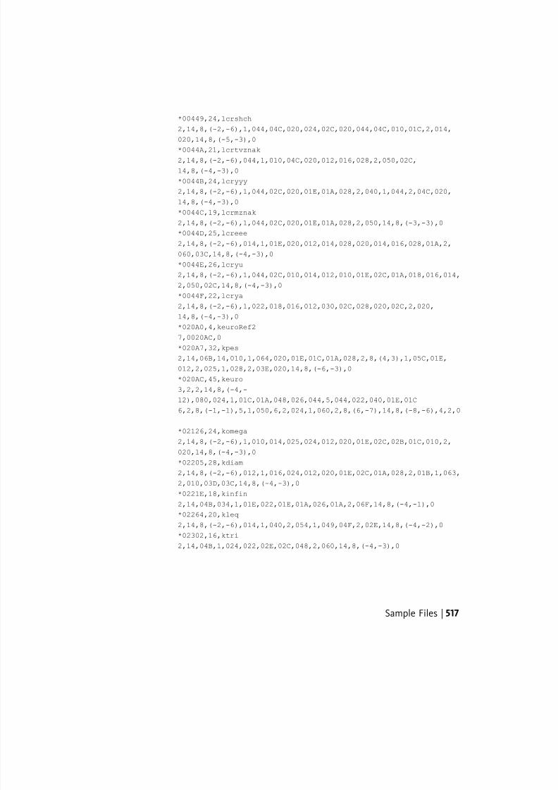
7/23/2019 Acad Customization
http://slidepdf.com/reader/full/acad-customization 525/553
*00449,24,lcrshch
2,14,8,(-2,-6),1,044,04C,020,024,02C,020,044,04C,010,01C,2,014,
020,14,8,(-5,-3),0*0044A,21,lcrtvznak
2,14,8,(-2,-6),044,1,010,04C,020,012,016,028,2,050,02C,
14,8,(-4,-3),0
*0044B,24,lcryyy
2,14,8,(-2,-6),1,044,02C,020,01E,01A,028,2,040,1,044,2,04C,020,
14,8,(-4,-3),0
*0044C,19,lcrmznak
2,14,8,(-2,-6),1,044,02C,020,01E,01A,028,2,050,14,8,(-3,-3),0
*0044D,25,lcreee
2,14,8,(-2,-6),014,1,01E,020,012,014,028,020,014,016,028,01A,2,
060,03C,14,8,(-4,-3),0
*0044E,26,lcryu
2,14,8,(-2,-6),1,044,02C,010,014,012,010,01E,02C,01A,018,016,014,2,050,02C,14,8,(-4,-3),0
*0044F,22,lcrya
2,14,8,(-2,-6),1,022,018,016,012,030,02C,028,020,02C,2,020,
14,8,(-4,-3),0
*020A0,4,keuroRef2
7,0020AC,0
*020A7,32,kpes
2,14,06B,14,010,1,064,020,01E,01C,01A,028,2,8,(4,3),1,05C,01E,
012,2,025,1,028,2,03E,020,14,8,(-6,-3),0
*020AC,45,keuro
3,2,2,14,8,(-4,-
12),080,024,1,01C,01A,048,026,044,5,044,022,040,01E,01C
6,2,8,(-1,-1),5,1,050,6,2,024,1,060,2,8,(6,-7),14,8,(-8,-6),4,2,0
*02126,24,komega
2,14,8,(-2,-6),1,010,014,025,024,012,020,01E,02C,02B,01C,010,2,
020,14,8,(-4,-3),0
*02205,28,kdiam
2,14,8,(-2,-6),012,1,016,024,012,020,01E,02C,01A,028,2,01B,1,063,
2,010,03D,03C,14,8,(-4,-3),0
*0221E,18,kinfin
2,14,04B,034,1,01E,022,01E,01A,026,01A,2,06F,14,8,(-4,-1),0
*02264,20,kleq
2,14,8,(-2,-6),014,1,040,2,054,1,049,04F,2,02E,14,8,(-4,-2),0
*02302,16,ktri
2,14,04B,1,024,022,02E,02C,048,2,060,14,8,(-4,-3),0
Sample Files | 517
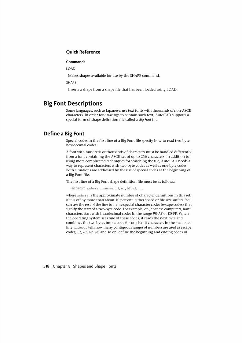
7/23/2019 Acad Customization
http://slidepdf.com/reader/full/acad-customization 526/553
Quick Reference
Commands
LOAD
Makes shapes available for use by the SHAPE command.
SHAPE
Inserts a shape from a shape file that has been loaded using LOAD.
Big Font DescriptionsSome languages, such as Japanese, use text fonts with thousands of non-ASCII
characters. In order for drawings to contain such text, AutoCAD supports a
special form of shape definition file called a Big Font file.
Define a Big FontSpecial codes in the first line of a Big Font file specify how to read two-byte
hexidecimal codes.
A font with hundreds or thousands of characters must be handled differently
from a font containing the ASCII set of up to 256 characters. In addition to
using more complicated techniques for searching the file, AutoCAD needs a
way to represent characters with two-byte codes as well as one-byte codes.
Both situations are addressed by the use of special codes at the beginning of
a Big Font file.
The first line of a Big Font shape definition file must be as follows:
*BIGFONT nchars,nranges,b1,e1,b2,e2,...
where nchars is the approximate number of character definitions in this set;
if it is off by more than about 10 percent, either speed or file size suffers. You
can use the rest of the line to name special character codes (escape codes) that
signify the start of a two-byte code. For example, on Japanese computers, Kanji
characters start with hexadecimal codes in the range 90-AF or E0-FF. When
the operating system sees one of these codes, it reads the next byte and
combines the two bytes into a code for one Kanji character. In the *BIGFONT
line, nranges tells how many contiguous ranges of numbers are used as escape
codes; b1, e1, b2, e2, and so on, define the beginning and ending codes in
518 | Chapter 8 Shapes and Shape Fonts
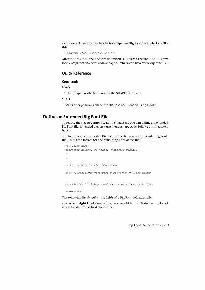
7/23/2019 Acad Customization
http://slidepdf.com/reader/full/acad-customization 527/553
each range. Therefore, the header for a Japanese Big Font file might look like
this:
*BIGFONT 4000,2,090,0AF,0E0,0FF
After the *BIGFONT line, the font definition is just like a regular AutoCAD text
font, except that character codes (shape numbers) can have values up to 65535.
Quick Reference
Commands
LOAD
Makes shapes available for use by the SHAPE command.
SHAPE
Inserts a shape from a shape file that has been loaded using LOAD.
Define an Extended Big Font FileTo reduce the size of composite Kanji characters, you can define an extended
Big Font file. Extended big fonts use the subshape code, followed immediately
by a 0.
The first line of an extended Big Font file is the same as the regular Big Font
file. This is the format for the remaining lines of the file:
*0,5,font-name
character-height, 0, modes, character-width,0
.
.
.
*shape-number ,defbytes,shape-name
.
code,0, primitive#,basepoint-x ,basepoint-y ,width,height,
.
.
code,0, primitive#,basepoint-x ,basepoint-y ,width,height,
.
terminator
The following list describes the fields of a Big Font definition file:
character height Used along with character width to indicate the number of units that define the font characters.
Big Font Descriptions | 519
7/23/2019 Acad Customization
http://slidepdf.com/reader/full/acad-customization 528/553
character width Used along with character height to indicate the number of
units that define the font characters. The character-height and
character-width values are used to scale the primitives of the font. In thiscontext, primitives are the points, lines, polygons, or character strings of the
font geometrically oriented in two-dimensional space. A Kanji character
consists of several primitives used repeatedly in different scales and
combinations.
modes The modes byte should be 0 for a horizontally oriented font and 2 for
a dual-orientation (horizontal or vertical) font. The special 00E (14) command
code is honored only when modes is set to 2.
shape-number Character code.
defbytes Byte size. It is always 2 bytes, consisting of a hexadecimal or a
combination of decimal and hexadecimal codes.
shape-name Character name.
code Shape description special code. It is always 7 so that it can use the
subshape feature.
primitive# Reference to the subshape number. It is always 2 bytes.
basepoint-x X origin of the primitive.
basepoint-y Y origin of the primitive.
width Scale of the width of the primitive.
height Scale of the height of the primitive.
terminator End-of-file indicator for the shape definition. It is always 0.
To arrive at the scale factor, AutoCAD scales down the primitive to a square
unit and then multiplies it by the height and width to get the shape of the
character. Character codes (shape numbers) in the Big Font shape definition
file can have values up to 65535. The following table describes the fields of
the extended Big Font file.
Fields of the extended Big Font file
DescriptionByte sizeValueVariable
Character code2 bytesxxxxshape-number
Extended font definition2 bytes7,0code
Refer to subshape number 2 bytesxxxx primitive#
520 | Chapter 8 Shapes and Shape Fonts
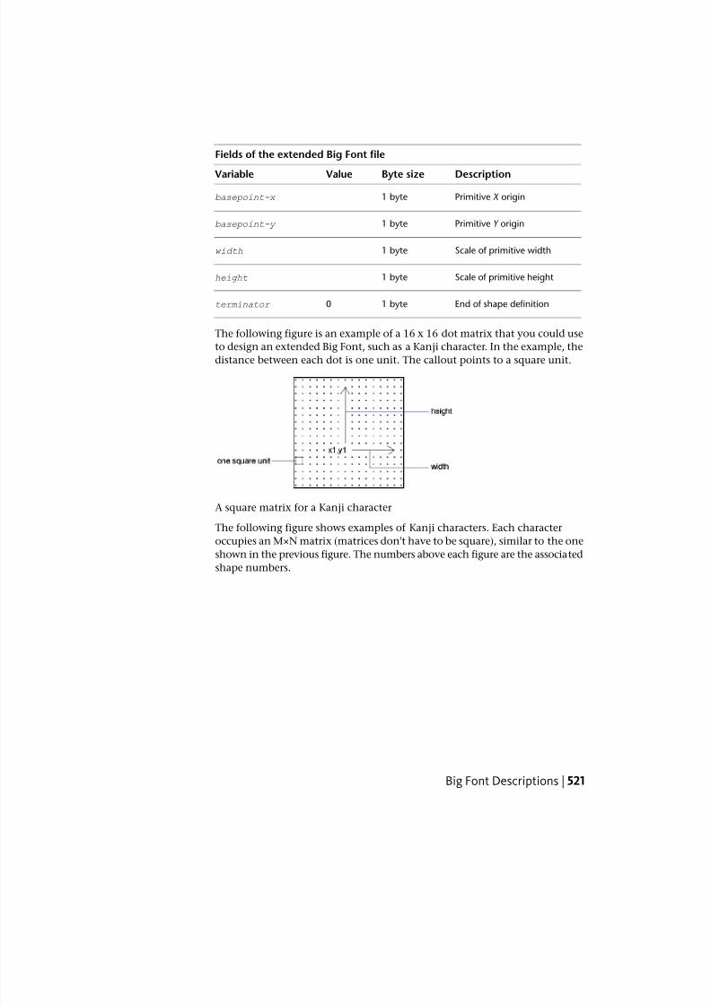
7/23/2019 Acad Customization
http://slidepdf.com/reader/full/acad-customization 529/553
Fields of the extended Big Font file
DescriptionByte sizeValueVariable
Primitive X origin1 bytebasepoint-x
Primitive Y origin1 bytebasepoint-y
Scale of primitive width1 bytewidth
Scale of primitive height1 byteheight
End of shape definition1 byte0terminator
The following figure is an example of a 16 x 16 dot matrix that you could use
to design an extended Big Font, such as a Kanji character. In the example, thedistance between each dot is one unit. The callout points to a square unit.
A square matrix for a Kanji character
The following figure shows examples of Kanji characters. Each characteroccupies an M×N matrix (matrices don't have to be square), similar to the one
shown in the previous figure. The numbers above each figure are the associated
shape numbers.
Big Font Descriptions | 521
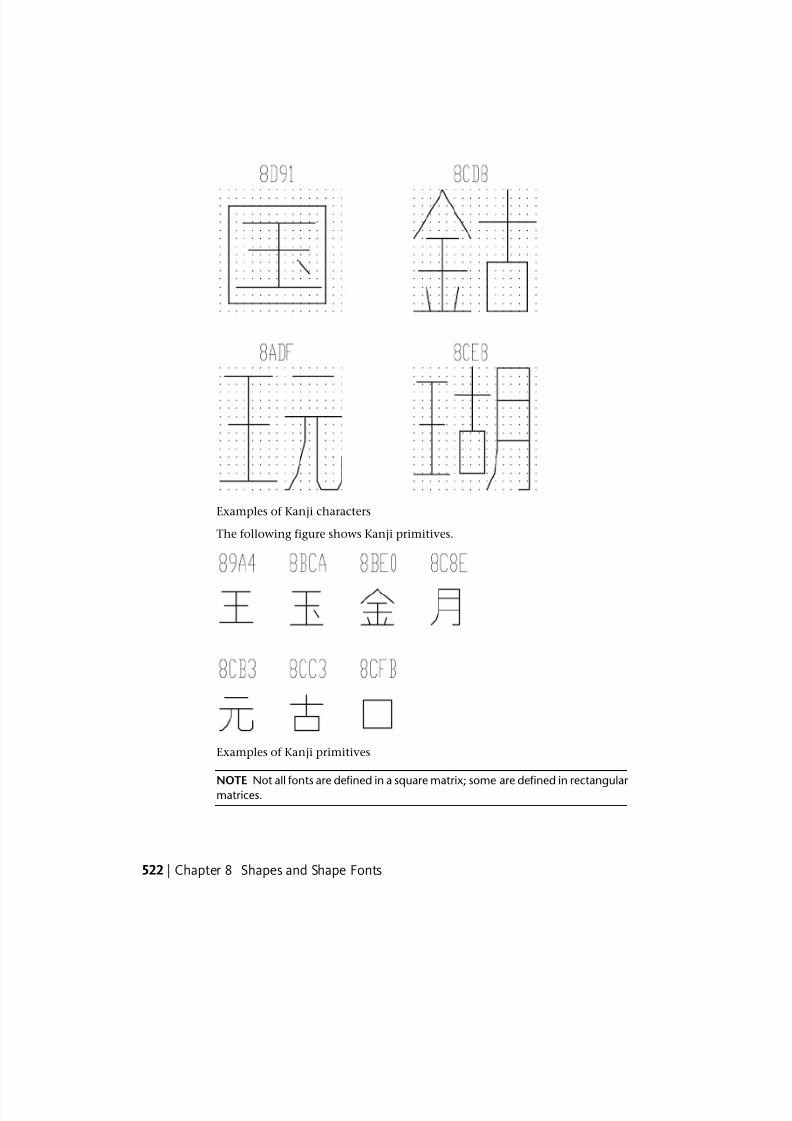
7/23/2019 Acad Customization
http://slidepdf.com/reader/full/acad-customization 530/553
Examples of Kanji characters
The following figure shows Kanji primitives.
Examples of Kanji primitives
NOTE Not all fonts are defined in a square matrix; some are defined in rectangular matrices.
522 | Chapter 8 Shapes and Shape Fonts

7/23/2019 Acad Customization
http://slidepdf.com/reader/full/acad-customization 531/553
Example: Shape Definition File for an Extended Big Font
Big Font Descriptions | 523
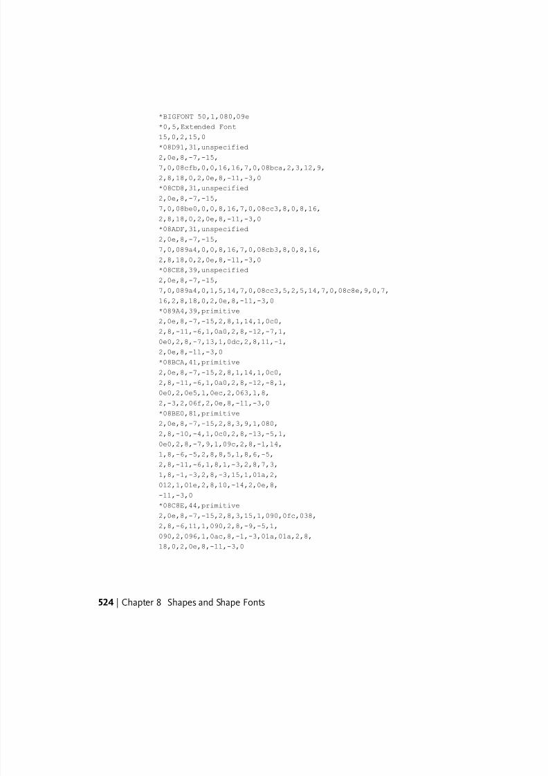
7/23/2019 Acad Customization
http://slidepdf.com/reader/full/acad-customization 532/553
*BIGFONT 50,1,080,09e
*0,5,Extended Font
15,0,2,15,0*08D91,31,unspecified
2,0e,8,-7,-15,
7,0,08cfb,0,0,16,16,7,0,08bca,2,3,12,9,
2,8,18,0,2,0e,8,-11,-3,0
*08CD8,31,unspecified
2,0e,8,-7,-15,
7,0,08be0,0,0,8,16,7,0,08cc3,8,0,8,16,
2,8,18,0,2,0e,8,-11,-3,0
*08ADF,31,unspecified
2,0e,8,-7,-15,
7,0,089a4,0,0,8,16,7,0,08cb3,8,0,8,16,
2,8,18,0,2,0e,8,-11,-3,0
*08CE8,39,unspecified2,0e,8,-7,-15,
7,0,089a4,0,1,5,14,7,0,08cc3,5,2,5,14,7,0,08c8e,9,0,7,
16,2,8,18,0,2,0e,8,-11,-3,0
*089A4,39,primitive
2,0e,8,-7,-15,2,8,1,14,1,0c0,
2,8,-11,-6,1,0a0,2,8,-12,-7,1,
0e0,2,8,-7,13,1,0dc,2,8,11,-1,
2,0e,8,-11,-3,0
*08BCA,41,primitive
2,0e,8,-7,-15,2,8,1,14,1,0c0,
2,8,-11,-6,1,0a0,2,8,-12,-8,1,
0e0,2,0e5,1,0ec,2,063,1,8,
2,-3,2,06f,2,0e,8,-11,-3,0
*08BE0,81,primitive
2,0e,8,-7,-15,2,8,3,9,1,080,
2,8,-10,-4,1,0c0,2,8,-13,-5,1,
0e0,2,8,-7,9,1,09c,2,8,-1,14,
1,8,-6,-5,2,8,8,5,1,8,6,-5,
2,8,-11,-6,1,8,1,-3,2,8,7,3,
1,8,-1,-3,2,8,-3,15,1,01a,2,
012,1,01e,2,8,10,-14,2,0e,8,
-11,-3,0
*08C8E,44,primitive
2,0e,8,-7,-15,2,8,3,15,1,090,0fc,038,
2,8,-6,11,1,090,2,8,-9,-5,1,
090,2,096,1,0ac,8,-1,-3,01a,01a,2,8,
18,0,2,0e,8,-11,-3,0
524 | Chapter 8 Shapes and Shape Fonts
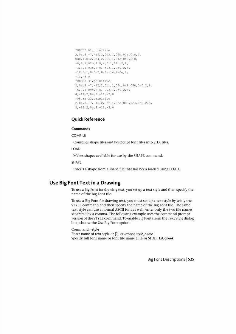
7/23/2019 Acad Customization
http://slidepdf.com/reader/full/acad-customization 533/553
*08CB3,61,primitive
2,0e,8,-7,-15,2,042,1,02b,02a,018,2,
0d0,1,012,034,2,069,1,01e,040,2,8,-8,6,1,02b,2,8,4,5,1,08c,2,8,
-3,8,1,03c,2,8,-5,3,1,0e0,2,8,
-12,5,1,0a0,2,8,6,-14,2,0e,8,
-11,-3,0
*08CC3,34,primitive
2,0e,8,-7,-15,2,0c1,1,06c,0a8,064,0a0,2,8,
-5,9,1,09c,2,8,-7,5,1,0e0,2,8,
4,-11,2,0e,8,-11,-3,0
*08CFB,22,primitive
2,0e,8,-7,-15,2,0d2,1,0cc,0c8,0c4,0c0,2,8,
5,-13,2,0e,8,-11,-3,0
Quick Reference
Commands
COMPILE
Compiles shape files and PostScript font files into SHX files.
LOAD
Makes shapes available for use by the SHAPE command.
SHAPE
Inserts a shape from a shape file that has been loaded using LOAD.
Use Big Font Text in a DrawingTo use a Big Font for drawing text, you set up a text style and then specify the
name of the Big Font file.
To use a Big Font for drawing text, you must set up a text style by using the
STYLE command and then specify the name of the Big Font file. The same
text style can use a normal ASCII font as well; enter only the two file names,
separated by a comma. The following example uses the command prompt
version of the STYLE command. To enable Big Fonts from the Text Style dialog
box, choose the Use Big Font option.
Command: -style
Enter name of text style or [?] <current >: style_name Specify full font name or font file name (TTF or SHX): txt,greek
Big Font Descriptions | 525
7/23/2019 Acad Customization
http://slidepdf.com/reader/full/acad-customization 534/553
AutoCAD assumes that the first name is the normal font and that the second
is the big font.
If you enter only one name, AutoCAD assumes it is the normal font and
removes any associated Big Font.
By using leading or trailing commas when specifying the font file names, you
can change one font without affecting the other, as shown in the following
table.
Input for changing fonts
ResultInput
Both normal and Big Font specifiednormal, big
Normal font only (Big Font unchanged)normal,
Big Font only (normal font unchanged) ,big
Normal font only (if necessary, Big Font removed)normal
No changeENTER (null response)
When you use the STYLE command to list styles or to revise an existing style,
AutoCAD displays the normal font file, a comma, and the Big Font file. If the
style has only a Big Font file, it is displayed with a leading comma: ,greek.
For each character in a text string, AutoCAD searches the Big Font file first. If
the character is not found there, the normal font file is searched.
Quick Reference
Commands
STYLE
Creates, modifies, or specifies text styles.
Use a Big Font to Extend a FontTo include special symbols in text strings, you can use a Big Font instead of
extending a standard text font.
526 | Chapter 8 Shapes and Shape Fonts
7/23/2019 Acad Customization
http://slidepdf.com/reader/full/acad-customization 535/553
In some drafting disciplines, many special symbols can appear in text strings.
The AutoCAD standard text fonts can be extended to include special symbols.
However, extending standard text fonts has several limitations:
■ The number of shapes is 255 per font file.
■ Standard character set uses almost half the available shape numbers. Only
codes 1 through 9, 11 through 31, and 130 through 255 are available.
■ Multiple text fonts require duplication of the symbol definitions in each
font.
■ Special symbols require that you enter %%nnn, where nnn is the symbol's
shape number.
The Big Font mechanism avoids these problems. You can select one or more
seldom-used characters, such as the tilde (˜) or the vertical bar (|), as an escapecode, and use the next character to select the appropriate special symbol. For
instance, you can use the following Big Font file to draw Greek letters by
entering a vertical bar (|, ASCII code 124) followed by the equivalent Roman
letter. Because the first byte of each character is 124, the character codes are
biased by 124 x 256, or 31744.
*BIGFONT 60,1,124,124
*0,4,Greek
above, below, modes, 0
*31809,n,uca
. . . uppercase Alpha definition, invoked by "|A"
*31810,n,ucb
. . . uppercase Beta definition, invoked by "|B"
*31841,n,lca. . . lowercase Alpha definition, invoked by "|a"
*31842,n,lcb
. . . lowercase Beta definition, invoked by "|b"
*31868,n,vbar
. . . vertical bar definition, invoked by "||"
. . .
Quick Reference
Commands
COMPILE
Compiles shape files and PostScript font files into SHX files.
Big Font Descriptions | 527
7/23/2019 Acad Customization
http://slidepdf.com/reader/full/acad-customization 536/553
LOAD
Makes shapes available for use by the SHAPE command.SHAPE
Inserts a shape from a shape file that has been loaded using LOAD.
Unicode Font DescriptionsA single Unicode font, due to its large character set, is capable of supporting
all languages and platforms. Unicode shape definition files are virtually
identical in format and syntax to regular AutoCAD shape definition files.
The main difference is in the syntax of the font header as shown in the
following code:
*UNIFONT,6,font-nameabove,below,modes,encoding,type,0
The font-name, above, below , and modes parameters are the same as in regular
fonts. The remaining two parameters are defined as follows:
encoding Font encoding. Uses one of the following integer values.
0 Unicode
1 Packed multibyte 1
2 Shape file
type Font embedding information. Specifies whether the font is licensed.
Licensed fonts must not be modified or exchanged. Bitcoded values can be
added.
0 Font can be embedded
1 Font cannot be embedded
2 Embedding is read-only
Another important difference is the handling of the code 7 subshape reference.
If a shape description includes a code 7 subshape reference, the data following
the code 7 is interpreted as a two-byte value. This affects the total number of
data bytes (defbytes) in the shape description header. For example, the
following shape description is found in the romans.shp file:
*00080,4,keuroRef
7,020AC,0
The second field in the header represents the total number of bytes in the
shape description. If you are not used to working with Unicode font
528 | Chapter 8 Shapes and Shape Fonts
7/23/2019 Acad Customization
http://slidepdf.com/reader/full/acad-customization 537/553
descriptions, you may be inclined to use three bytes rather than four, but this
would cause an error during the compiling of the SHP file. This is true even
if the shape number you are referencing is not in the two-byte range (below255); the compiler always uses two bytes for this value, so you must account
for that in the header.
The only other difference between Unifont shape definitions and regular shape
definitions is the shape numbers. The Unifont shape definitions that AutoCAD
provides use hexadecimal shape numbers as opposed to decimal values.
Although hexadecimal numbers are not required, their use makes it easier to
cross-reference the shape numbers with the \U+ control character values.
Quick Reference
Commands
LOAD
Makes shapes available for use by the SHAPE command.
SHAPE
Inserts a shape from a shape file that has been loaded using LOAD.
Superscripts and Subscripts in SHX FilesYou can modify shape definition files to improve their ability to display
superscripts and subscripts.
The AutoCAD SHX fonts have limited superscript and subscript capabilities.
However, it is relatively easy to modify shape definition files to improvesuperscript and subscript capability.
Creating superscripts and subscripts requires two steps. First, the “imaginary
pen” that is creating the text, vector by vector, on your screen needs to be
shifted up or down. Then, the font “scale” needs to be reduced. In addition,
the reverse process has to take place to return to the normal font. The font
needs to recognize four new keys: two for superscripts and two for subscripts.
To avoid altering the existing font definitions, you can access these with the
numeric keypad on your keyboard.
To add superscript and subscript definitions to a font
This example procedure is based on the AutoCAD Romans font file, although
a similar method applies to any AutoCAD font. This procedure adds four newshape definitions to a font: super_on, super_off, sub_on, and sub_off, which
Superscripts and Subscripts in SHX Files | 529
7/23/2019 Acad Customization
http://slidepdf.com/reader/full/acad-customization 538/553
control the position and size of the characters that follow. For simplicity, this
example replaces the left- and right-bracket characters ([and]) and the left and
right curly brace characters ({and}) with the new characters. You may chooseto replace other characters or use a shape number in the extended range (ASCII
codes 128 through 256). If you use an extended shape number, you need to
use the %%nnn method (where nnn is the ASCII value of the character) for
placing the new characters.
1 Edit your SHP file with an ASCII text editor.
2 Search for the shape definitions of the characters you are replacing. To
comment out those definitions so the new definitions can take their
place, insert a semicolon in front of each line of the shape definition.
The shape definition may continue for a number of lines.
The left- and right-bracket characters have ASCII values of 91 and 93 (05B
and 05D hex values, if the font is Unicode). The left and right curly brace
characters have ASCII values of 123 and 125 (07B and 07D hex).
3 Add the first and second values on the second line of the definition, and
divide the total by 2 as shown in the following example:
*UNIFONT,6,Extended Simplex Roman for UNICODE
21,7,2,0 21 + 7 = 28, then 28 / 2 = 14. This number is used
later.
4 Add the following lines to the end of the SHP file:
*91,8,super_on
2,8,(0,14),003,2,1,0
*93,8,super_off
2,004,2,8,(0,-14),1,0
*123,8,sub_on2,8,(0,-14),003,2,1,0
*125,8,sub_off
2,004,2,8,(0,14),1,0
Notice the 14 and -14 values in the preceding lines. They are Y axis offsets
for the imaginary pen. The value 14 is half the maximum height of a
character in this font, which is the correct approximation for superscripts
and subscripts. This value needs to be calculated for each font file, but
you can modify it any way you want.
5 Save the file.
6 Use the COMPILE command to compile the SHP file.
Once the shape is compiled and an appropriate style is defined, you can
access the new pen-up and pen-down commands by entering the [, ], {,
530 | Chapter 8 Shapes and Shape Fonts

7/23/2019 Acad Customization
http://slidepdf.com/reader/full/acad-customization 539/553
and } characters. The [ character initiates superscript and the ] character
returns from superscript to normal. The { character initiates subscript and
the } character returns from subscript to normal.
Quick Reference
Commands
COMPILE
Compiles shape files and PostScript font files into SHX files.
LOAD
Makes shapes available for use by the SHAPE command.
SHAPE
Inserts a shape from a shape file that has been loaded using LOAD.
Superscripts and Subscripts in SHX Files | 531

7/23/2019 Acad Customization
http://slidepdf.com/reader/full/acad-customization 540/553
532
7/23/2019 Acad Customization
http://slidepdf.com/reader/full/acad-customization 541/553
Index
.NET Frameworkabout 451loading applications 451
A
abbreviations for commands 24absolute menu referencing 288acad.lsp file 442acaddoc.lsp file 443accelerator keys 309, 314, 317, 322
action macrosabout 25Action Recorder 28, 49base points 46coordinates 44modifying 38, 51node icons 33object selection 47pausing 43playback 51recording 29, 49samples 52saving 30sharing 51user input 43user messages in 42
Action Recorderabout 28action macros 25node icons 33recording actions 29sample macros 52tips for recording macros 49
actions (user)double click actions 324
ActiveX Automationabout 429starting applications with 431Visual Basic for Applications
and 429, 432
addition DIESEL function 402aliases
creating for commands 24pull-down menus 271, 290shortcut menus 275
alignmentlinetype patterns 65
alternate font mapping files 13and DIESEL function 406angtos DIESEL function 406APIs (application programming
interfaces) 429
applications.NET Framework 451ActiveX Automation 429AutoLISP 437ObjectARX 447programming applications 429starting with ActiveX
Automation 431starting with commands 431Visual Basic for Applications 432Visual LISP 437
AutoCADcustomization 1
AutoCAD Runtime Extension 447
AutoLISP (LSP) applicationsabout 437acad.lsp file 442acaddoc.lsp file 443customizing interface 346customizing status line 396DIESEL expressions and 399errors when loading 445loading 439–440loading ObjectARX applications
with 448macros and 151, 163, 399MNL files 444S STARTUP function 446
system variables and 438Automation controllers 429
Index | 533
7/23/2019 Acad Customization
http://slidepdf.com/reader/full/acad-customization 542/553
Automation objects 430
B
backup filescustomization files 122
base points 46batch files 9Big Fonts
about 518defining 518examples 521extended Big Font files 519extending text fonts with 527text styles and 525
blocks
action macros and 57borders (menu items) 166buttons
crosshair coordinates 334customizing 248drop-downs 220flyouts 260images on 248moving 248pointing device buttons 118, 331ribbon controls 224swapping 161, 290tablet buttons 336
C
C# programming language 451canceling commands 152caret syntax in macros 154cascading menus 271categories
commands 93CFG files 13characters
Big Fonts 518including in linetypes 68macro control characters 151, 154shape fonts 453
clicking actions 324, 331cmd (Windows system command) 22
codes (shape specification bytes) 458COM architecture 429
command lineswitches 425
command line switchesrunning scripts and 425
Command List pane (CUI editor) 93command scripts 422commands
about 142aliases 24canceling 152categories 93creating 144custom-defined 23customization FAQs 388
customizing 106, 142double click actions 324drop-downs 220editing 144external commands 20flyouts 260Help topics about 174images for 181, 184, 186listing 93macros and 151–152, 159menu referencing 288name validity 5pausing for input 156properties 142
pull-down menus 114, 270Quick Access toolbar 194rearranging 92recording in action macros 29repeating 159reusing 144ribbon panels and 201screen menus and 337scripts 422shortcut menus and 116, 270starting applications with 431status line messages 180submenus and 285swapping menu contents 161tablet buttons and 336tagging 171
534 | Index
7/23/2019 Acad Customization
http://slidepdf.com/reader/full/acad-customization 543/553
tooltips 174transparent commands 156
Windows system commands 22comments
AutoLISP commenting 439script commenting 422
compiling shape or font files 453component object model
architecture 429conditional expressions in macros 162configuration files (plotters)
locating 13multiple 7
configuration files (pointing devices)locating 13multiple 7
contextual ribbon tabs 112, 245control characters in macros 154controls
ribbon controls 224ribbon panels 201toolbar controls 265
coordinatesaction macros and 44base points 46reading with pointing devices 334
copyingbuttons to other toolbars 248customization file data 384list of shortcut keys 309
copyright restrictions on fonts 454crosshairscoordinates of 334
CUI (customization) filesbackwards compatibility 97CUIx files 90defined 103migrating to CUIx 384structure 99
CUI Editorabout 87, 90, 106changes in customization and 97,
387Command List pane 93Customizations In pane 92
customizing workspaces 119, 348,364
Dynamic Display pane 95FAQs 387tree nodes 104
CUIx (customization) filesbackups 122backwards compatibility 97creating 122CUI Editor 90, 106customization FAQs 390defined 103enterprise CUIx files 131finding items in 135importing workspaces 350menu swapping 292
migrating older files to 384partial CUIx files 127structure 99XML-based format 97
current workspaces 350custom icon files 13custom-defined commands 23customization
about 1customization files (CUI)
backwards compatibility 97CUIx files 90defined 103DIESEL expressions in 399
directory structure and 5locating files 13migrating to CUIx 384structure 99
customization files (CUIx)about 90, 122backups 122backwards compatibility 97creating 122CUI Editor 106customization FAQs 390defined 103enterprise CUIx files 131finding items in 135importing workspaces 350menu swapping 292
Index | 535
7/23/2019 Acad Customization
http://slidepdf.com/reader/full/acad-customization 544/553
migrating older menu files to 384partial CUIx files 127
structure 99XML-based format 97
customization groups 101, 103Customizations In pane (CUI editor) 92Customize User Interface editor
about 87, 90, 106changes in customization and 97Command List pane 93Customizations In pane 92customizing workspaces 119, 348,
364Dynamic Display pane 95FAQs 387tree nodes 104
customizingabout customization 87AutoCAD functions and features 1commands 106, 142Customize User Interface editor 87,
106double click actions 117, 324FAQs for 387glossary of terms for 103hatch patterns 75hatches 75images for commands 184legacy interface elements 334linetypes 63
locating customized files 10migrating older customizationfiles 384
mouse button actions 118, 331properties 293pull-down menus 114, 270Quick Access toolbar 194ribbon 109, 201, 362scripts and 346shortcut keys 117shortcut menus 116, 270status line 393–394, 396tablet buttons 336templates 17toolbars 108, 113, 248tooltips 302
types of customized files 10user interface 87, 122
windows 365workspaces 119, 347, 361
D
dashboard panel 103dashes
hatch pattern definitions 78linetype definitions 64
data linkslocating files 10
datesedtime DIESEL function 407
DCL files (dialog control language) 13,
438delaying slide shows 426deleting
menus 290ribbon items 208toolbar buttons 248
DesignCenteraction macros and 36
dialog boxesimage tile dialog boxes 341
DIESEL expressionsabout 393customizing status line 395error messages 415
macros and 151, 162, 399nesting 395pull-down menu labels 401quoted strings in 396
DIESEL functionsaddition 402and 406angtos 406catalog 402division 403edtime 407eq 409equal to 404eval 409
fix 410getenv 410
536 | Index
7/23/2019 Acad Customization
http://slidepdf.com/reader/full/acad-customization 545/553
getvar 411greater than 405
greater than or equal to 406if 411index 411less than 404less than or equal to 405multiplication 403not equal to 405nth 412or 412rtos 413strlen 413substr 413subtraction 403upper 414
xor 414digitizing tablets
buttons 331, 336dimensions
font characters for 468direction
shape specification codes 456directories 4directory paths
AutoLISP files 440program and support files 4
displayingcontextual ribbon tabs 112hidden files 10
list of shortcut keys 309menus 366palettes 362, 366Quick Access toolbar 362, 365ribbon panels 362, 365ribbon tabs 362, 365slide shows 426slides 419toolbars 362, 366tooltips 302workspace toolbars 248
division DIESEL function 403docked windows 104dots in linetype definitions 64double click actions
customization FAQs 389
customizing 117, 324drawing files (DWG)
folders and maintenance 8slides of 417
drawing templateslocating files 16
drop-down lists 224, 265drop-downs
ribbon panels 220DWT files
locating 16Dynamic Display pane (CUI editor) 95Dynamic Help 101
E
echoes in macros 153editing
action macros 38, 51commands 144double click actions for 324shortcut keys 309slide files and 419toolbars 250
edtime DIESEL function 407element IDs 103enterprise customization files
about 122creating 131customization FAQs 390
defined 103eq DIESEL function 409equal to DIESEL function 404error messages
AutoLISP 445DIESEL 415
errorsAutoLISP errors 445
eval DIESEL function 409events 430exporting images for commands 186extended Big Font files 519extended help 174external commands 20
Index | 537
7/23/2019 Acad Customization
http://slidepdf.com/reader/full/acad-customization 546/553
F
FAS files 438fields (font definition files)
Big Font files 519shape font files 455
fileslocations 4, 10maintenance 8roaming profiles and 10
findingcommands in CUIx files 135customized files 10tagged commands 171
fix DIESEL functions 410floating windows 104
flyoutsbuttons 260toolbars 260
FMP files (font mapping) 13folders
file locations 4font mapping files 13fonts
compiling 453creating 467dimensioning characters in 468including in linetypes 68shape fonts 453special symbols in 527
superscripts and subscripts in 529function keys (F1-F12) 309, 314, 317,322
G
getenv DIESEL function 410getvar DIESEL function 411graphics for commands 181, 184, 186graying out menu item labels 165greater than DIESEL function 405greater than or equal to DIESEL
function 406
H
hatch patternsabout 75creating 75examples 75, 79, 82multiple lines 82
hatchescreating 75customizing 75
HelpDynamic Help 101locating Help files 13tooltip command Help 174
hidden files 10hiding
toolbar buttons 248
I
iconsaction macros 33customizations 13
if DIESEL function 411image tile menus
creating 341menu swapping 290slides and 420
images for commands 181, 184, 186importing
customization file data 384images for commands 186workspace settings 350
index DIESEL function 411input
action macros 43pausing macros for 156prompting for 164
insertingmenus 290
interfaceaction macros and 36changes in customization process 96customization FAQs 387
Customize User Interface editor 87,106, 364
538 | Index
7/23/2019 Acad Customization
http://slidepdf.com/reader/full/acad-customization 547/553
customizing 87legacy interface elements 334
terminology 103workspaces 119
interface elementsdefined 103swapping 161, 290tree view 92
interface items 103international character sets 158, 518–
519Internet
customizing templates for 17
J
Japanese fonts 518–519
K
Kanji fonts 518–519keyboard input in macros 156keyboard shortcuts 117, 309, 314, 317,
322
L
languagesBig Fonts 519
macro translations 158special character codes 518layers
action macros and 52legacy interface elements 104, 334less than DIESEL function 404less than or equal to DIESEL
function 405library search path 4LIN files (linetype library) 13, 63linetypes
about 63complex 71creating 64customizing 63examples 64
including shapes in 71simple 64
text characters in 68listing
commands 93keyboard shortcuts 309
loading.NET Framework applications 451AutoLISP applications 439–440,
442–444AutoLISP macros 346customization files 122ObjectARX applications 448–449partial customization files 127VBA applications 435VBA projects 434
LSP files (AutoLISP) 438–439
M
macrosabout 151action macros 25ActiveX programming 429AutoLISP expressions in 163, 399automatically loading 436commands in 159conditional expressions in 162defined 104DIESEL expressions in 162, 399
international language support 158length 153pausing for user input 153, 156prompting for user input 164repeating commands 159scripts 422selecting objects with 160shortcut keys and 309special character codes for
commands 154starting applications with 431suppressing echoes and
prompts 153swapping interface elements
with 161syntax 151
Index | 539
7/23/2019 Acad Customization
http://slidepdf.com/reader/full/acad-customization 548/553
tablet menus and 334terminating 153
main customization files 104, 122MDE (Multiple Design
Environment) 437menu files 97menu groups (customization
groups) 101, 103menu items
action macros and 36DIESEL expressions and 401disabling 165graying out 165status line messages 180
menu referencing 288menu resource files (MNR) 97
menu swapping 161, 292menu template files (MNU) 97, 104menus
action macros and 36AutoLISP MNL files 444creating 114, 116, 270customization FAQs 388customizing 114, 116, 270international language support 158legacy interface elements 104macros and 431menu files 97menu referencing 288pull-down menus 114, 271
rearranging commands 92removing 290screen menus 337shortcut menus 116starting applications from 431submenus 285swapping 161, 290tablet menus 334workspace arrangements 366
messages (instruction) 42methods 430Microsoft .NET Framework 451Microsoft Visual Basic for
Applications 432migrating
customization FAQs 387
menu files from previousreleases 384
MNC files 97MNL files (menu LISP)
customization and 97, 346loading 440, 444locating 13macros and 163
MNR files (menu template) 97MNS files (source menu)
changes in customization and 97defined 104migrating 384
MNU files (menu template)changes in customization and 97defined 104
migrating 97, 384model space
slides created in 418modifying
action macros 38commands 144double click actions for 324shortcut keys 309toolbars 250
mousecoordinates of crosshairs 334customizing button actions 118,
331double click actions 324
swapping actions 161multiple configuration files 7Multiple Design Environment 437multiple-line hatch patterns 82multiplication DIESEL function 403
N
namespaces in Visual LISP 437naming
linetypes 65shapes 456
NET Framework 451networks
enterprise customization filesand 131
540 | Index
7/23/2019 Acad Customization
http://slidepdf.com/reader/full/acad-customization 549/553
nodesaction macro icons 33
interface customization 104not equal to DIESEL function 405nth DIESEL function 412number pad keys 309, 314, 317, 322
O
object propertiescustomizing 293
ObjectARX applications.NET managed wrapper classes 451about 447loading 448–449
objects
double click actions 327properties 293shortcut menus 276
or DIESEL function 412
P
palettesdefined 104displaying 362workspaces and 366, 380
paper spaceslides created in 418
partial customization filesabout 122creating 127defined 104toolbars and 292
partial menu files 290PAT files 13patterns
linetypes 66pausing
macros 43pausing macros 153, 156PFB files (printer font binary) 454PGP files (program parameters) 13playing action macros 51
plot styleslocating files 11
plotter configuration fileslocating files 11
multiple files 7PMP files (plot model parameter) 12pointing devices
coordinates of crosshairs 334customizing button actions 331double click actions 324multiple configuration files 7swapping actions 161
PostScript fonts 454prefixes for commands 25preloading slides 426previous releases
backwards compatibility 97changes in customization process 96
legacy interface elements 334migrating custom settings from 384
printinglists of shortcut keys 309
profiles 10program file locations 4programming applications
.NET 451about 429ActiveX Automation 429AutoLISP 437ObjectARX 447Visual Basic for Applications 432Visual LISP 437
promptssuppressing 153user input in macros 164
propertiesaction macros and 59commands 142customizing 293programming properties 430Quick Properties panel 293toolbars 248workspaces 349
PSF files 13Publish to Web wizard
customizing templates 17pull-down menus
creating 114, 271
Index | 541
7/23/2019 Acad Customization
http://slidepdf.com/reader/full/acad-customization 550/553
customizing 114, 270, 290menu referencing 288
starting applications from 431
Q
Quick Access toolbar 104, 108, 194, 362,365
Quick Properties panel 293
R
rearrangingmenus 92ribbon items 208ribbon tabs 238toolbar buttons 248
recordingaction macros 29
referencing menus 288, 290relative menu referencing 288removing
menus 290ribbon items 208toolbar buttons 248
repeating commands 159replacing
commands in CUIx files 135ribbon
action macros and 36command images 181, 184, 186contextual tab states 112, 245controls 224customizing 109, 201defined 104drop-downs on panels 220reorganizing command and
controls 208ribbon panels 104, 109ribbon tabs 111–112, 238workspaces and 365
ribbon panelsadding items to 208controls for 224
creating 109customizing 201, 362
defined 104drop-downs on 220
rearranging 365ribbon tabs
contextual tab states 112, 245creating 111, 238customizing 362rearranging 365
roaming profiles 10rollover tooltips 302rows (ribbon) 201rtos DIESEL function 413
S
S STARTUP AutoLISP function 446
savingaction macros 30
SCR files (scripts) 422screen menus 337scripts
about 417, 422customizing user interface 346file names and 422, 425running at startup 424running slide shows from 426switches and 425
search pathsdefault file locations 4
searching
finding commands in CUIx files 135finding tagged commands 171
selectingaction macro object selections 47objects with macros 160
shape definition filesabout 453Big Font files 518creating 453, 455samples 469, 498superscripts and subscripts 529text fonts 467Unicode fonts and 528
shape fonts
about 453Big Fonts 518
542 | Index
7/23/2019 Acad Customization
http://slidepdf.com/reader/full/acad-customization 551/553
sample files 469, 498superscripts and subscripts 529
Unicode shape definition files 528shape specification bytes 458shapes
about 453descriptions 455including in linetypes 71shape specification bytes 456special codes 458
shortcut keysassigning 309customizing 117defaults 314temporary override keys 317, 322
shortcut menus
aliases 275context-sensitive shortcut
menus 275creating 116, 275customizing 116, 270double click actions 324menu referencing 288
SHP fonts (shape definition) 453, 455SHX fonts 13, 453, 455, 529slide libraries 343, 420slide shows 426SLIDELIB utility 420slides
about 417
creating 417editing commands and 419image tile menus and 341, 343, 420preloading 426slide libraries 420slide shows 426viewing 419
source menu files (MNS) 97, 104, 384spaces in linetypes 64special characters
commands and 285image tile menus 341macros and 151, 154, 285shape fonts 453
start (Windows system command) 22
startingapplications with ActiveX
Automation 431applications with commands 431
startup AutoLISP errors 445startup scripts 424status line 180, 393–394, 396strings in CUIx files 135strlen DIESEL function 413submenus 285subscripts in fonts 529substr DIESEL function 413subtraction DIESEL function 403superscripts in fonts 529support files
locations 4, 13
suppressing echoes and prompts 153swapping
interface elements with macros 161menus 290
switchesrunning scripts and 425
switchingtoolbar controls 265
symbolscommands and 285image tile menus 341macros and 151, 154, 285shape fonts 453
syntax
macros 152shape fonts 455Unicode shape definition files 528
system variablesAutoLISP functions and 438toggling values with macros 162
T
tabletscustomizing buttons 331, 336customizing menus 334menu swapping 161, 290
tags
element IDs 103menu commands 171
Index | 543
7/23/2019 Acad Customization
http://slidepdf.com/reader/full/acad-customization 552/553
templatescustomizing 17
locating files 16temporary override keys 317, 322terminating macros 153text
including in linetypes 68shape fonts 453
text stylesBig Fonts and 525
textureslocating files 17
timeedtime DIESEL function 407
tool palettesaction macros and 36
toolbar buttonscustomizing 248images 248rearranging 92, 248
toolbarsaction macros and 36command images 181, 184, 186controls on 265creating 113, 250customization FAQs 388customizing 113, 248displaying 362flyouts on toolbar buttons 260naming 248
partial CUIx files and 292properties 248Quick Access toolbar 108, 194, 365rearranging elements on 92starting applications from 431workspace arrangements 366
tooltipscommand Help in 174customizing 302
transferring customization files 384translating macros 158transparent commands 156tree nodes 104Type 1 PostScript fonts 454
U
Unicode fonts 498, 528Unicode shape definition files 528unique IDs (element IDs) 103unloading
partial customization files 127UNT files 13updating
customization files 384upgrading
customization FAQs 387migrating customization files 384
upper DIESEL function 414user input
action macros 43
pausing macros 156user interface
action macros and 36changes in customization process 96customization FAQs 387Customize User Interface editor 87,
106, 364customizing 87legacy interface elements 334terminology 103workspaces 119
V
VB 6 432, 434VB.NET programming language 451VBA macros
about 432ActiveX Automation and 429command line execution 434loading 434–435
VBP files 434vectors in shape specifications 456Visual Basic 6 432, 434Visual Basic for Applications
about 432ActiveX Automation and 429, 432loading projects 434–435
Visual LISP 437VLISP (Visual LISP) 437
544 | Index

7/23/2019 Acad Customization
http://slidepdf.com/reader/full/acad-customization 553/553
VLX files (Visual LISP) 438
W
web pagestemplates 17
windowscustomizing 365workspaces and 380
customization FAQs 390customizing 119, 347, 361
defined 104importing 350properties 349ribbon tabs 238toolbars in 248
X