ac servo system - 伯錦電機有限公司
TRANSCRIPT

www.seec.com.tw
ISO 14001BSMI
REGISTERED認可登錄
CERT. NO. 4A4E003
ISO 9001BSMI
REGISTERED認可登錄
CERT. NO. 4A4Y003
AC Servo System SDA Series 100W~3.5KW

1 ▲ ▲ ▲
Features 2
Model Description 4
Product Corresponding Table 5
Connections with Peripheral Equipment 6
Servo Amplifier Appearance and Panel Descriptions 7
Standard Wiring Diagram 8
Servo Amplifier Specifications 12
Servo Motor Specifications 13
Servo Motor Torque Characteristic 14
Motor Shaft Dimensions 15
Electromagnetic Brake Specifications 15
Servo Amplifier Dimensions 16
Servo Motor Dimensions 18
Optional Cables and Connectors 20
INDEX

▲ ▲ ▲
2
Shihlin AC Servo Systems
High speed and high-accuracy
High speed frequency response amplifiers (490Hz) and high command settling time (less •
than 1.0ms).
At no load situation, when the motor speed is between 3000rpm to -3000rpm, the •
accelerate time is 6.9ms.
Test example of 400W
Multiple control modes for various applications
Position control mode, speed control mode, torque control mode, and single-axis position •
control mode.
Different control modes could be set as hybrid mode via switching I/O.•
Built-in single-axis control mode
Build-in linear and S curve acceleration/deceleration parameters.•
Build-in linear and S curve acceleration/deceleration parameters.•
Various home position return modes.•
Modbus communication and USB interface
Support Modbus communication protocol.•
Support USB communication.•
RS232/RS485 interface.•
Support baud rate from 4800 to 115200 bps.•
0.19 0.2 0.21 0.22 0.23 0.24 0.25 0.26 0.27 0.280
50
100
150
200
250
300
350
400
Pulse Value
Settling Time Test
Time (sec)X: 0.2488Y: 0
X: 0.2588Y: 5
Command Pulse Frequency
Pulse Error
70 80 90 100 110 120 130 140-4000
-3000
-2000
-1000
0
1000
2000
3000
4000 X: 96.4Y: 3000
SDA-L040 rotor speedfrom 3000rpm to -3000rpm under no-load response
Time (msec)
Rotor speed (rpm)
X: 103.2Y: -3025
Feedback Rotor Speed

3 ▲ ▲ ▲
Mechanical resonance filter setup
The user can set up two mechanical resonance •
points to suppress mechanical vibration.
Auto tuning function
There is an automatic on-line •
control theory to achieve a
stable control.
Highly potent servo software
A variety of functions are available for •
the customers.
Status monitoring.•
Parameter data reading and writing; file •
reading and saving, output printing.
Digital I/O monitoring and internal digital •
input controlling.
Jog testing and position testing.•
Automatic inertia estimation and gain •
calculation.
FFT resonance sweep function.•
Oscilloscope long-term status capturing •
function.
CE certification
EMC•
IEC 61800-3
IEC 61800-4
Safety•
IEC 61800-5-1

▲ ▲ ▲
4
Shihlin AC Servo Systems
■ Servo Motor
■ Servo Amplifier
S M A ―□ ○○○ R△△ A □ □
S D A ― ○ ○ ○ △ △
Shaft type: No note: normalK: keyway
Motor type: A: No brake, no oil
sealB: With brake but no
oil sealC: No brake, with oil
sealD: With brake and oil
seal
Encoder Resolution: A: 2500 PPR (Incremental)
Motor Rated Rotation Speed: R20: 2000 RPMR30: 3000 RPM
SERVO MOTOR
Inertia Classification: M: Medium InertiaL : Low Inertia
Type: A Series
Motor Capacity: 010: 100W 100: 1KW020: 200W 150: 1.5KW040: 400W 200: 2KW050: 500W 350: 3.5KW075: 750W
Corresponding Motor Capacity: 010: 100W 100: 1KW020: 200W 150: 1.5KW040: 400W 200: 2KW050: 500W 350: 3.5KW075: 750W
Input Voltage: A2: 3-phase 220V
SERVO DRIVER
Type: A Series

5 ▲ ▲ ▲
Servo Amplifier
Capacit 100W 200W 400W 500W 750W 1KW 1.5KW 2KW 3.5KW
Model SDA-010A2
SDA-020A2
SDA-040A2
SDA-050A2
SDA-075A2
SDA-100A2
SDA-150A2
SDA-200A2
SDA-350A2
Appearance
Servo Motor
Low
Inertia
Capacit 100W 200W 400W 750W
Model SMA-L010R30AA
SMA-L020R30AA
SMA-L040R30AA
SMA-L075R30AA
Appearance
Medium
Inertia
Capacit 500W 1KW 1.5KW 2KW 3.5KW
ModelSMA-
M050R20AC
SMA-
M100R20AC
SMA-
M150R20AC
SMA-
M200R20AC
SMA-
M350R20AC
Appearance
▲ ▲ ▲
6
Shihlin AC Servo Systems
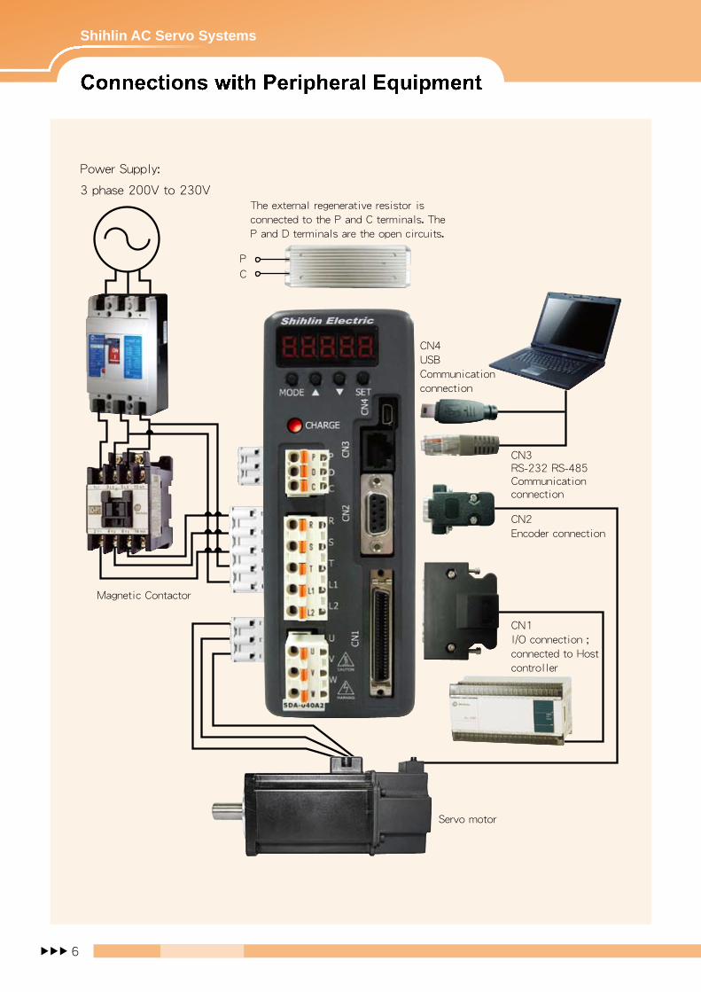
CN4USBCommunicationconnection
CN3RS-232 RS-485Communication connection
CN2Encoder connection
CN1I/O connection ;connected to Hostcontroller
Servo motor
Magnetic Contactor
The external regenerative resistor isconnected to the P and C terminals. TheP and D terminals are the open circuits.
Power Supply:
3 phase 200V to 230V
PC

7 ▲ ▲ ▲
Power Indicator Light:If the light is on, it indicatesthat the servo amplifier stillhas a high voltage.
Internal/External Regenerative Resistor :a) When using the external
regenerativeresistor, connect P and C terminals to theresistor, and make P and D the open circuits.
b) When using the internal regenerativeresistor, make P and C terminals the opencircuits, and make P and D terminals theshort circuits.
Control Circuit Power :L 1 and L 2 for single -phaseAC 200 – 230V , 50/60 HzPower Supply
Main Circuit Power :Connect R, S, and T tocommercial electrical powerof AC 200 – 230V and 50/60Hz.
Servo Motor Output :Connect to U, V , and W ports of the motor power. C annot be connected to the main circuit power. Wrong connection can cause servo amplifier damages.
Heatsink :Fix the servo amplifier andheatsink the temperature.
LED Display :The 5-digit, 7-segment LEDdisplays the alarm code, servo status, parameters, etc
Operation Panel :Operation status includes setups forfunction, parameter, etc.MODE : Mode options▲: Increase value on the
display panel▼: Decrease value on the
display panelSET : Set: To set data
USB Connection :Connect to PC and servo amplifier.
RS-232 / RS-485Connection :Connect to PC and servo amplifier
Encoder Connector :It is to connect to the encoder of servo motor.
Control Connection :Can be connected to the externalcontrol I/O connector or to the PLC .
Ground

▲ ▲ ▲
8
Shihlin AC Servo Systems
■ Built-in single-axis position control (PR)
P
PE
D
WVUC
Servo Motor
Encoder
+5V
B
/A
A
GND
/Z
Z
/B
CN2
SD
LA
LZR
LZ
LBR
LB
LAR
SD
OP
LG
RS-232-RX
RS-232-TX
GND
CN3
MON1
LG
MON2
A
A
SD
R
L1
L2
TS
MCMCCB
CN1VCC
TC
LG
SD
VDD
DI7
DI6
DI5
DI4
DI3
DI2
DI1
COM+
SG
DI8
VDD
DO2
DO1
COM+
DO5
DO4
DO3
RA1
RA1RA3
RA2
RA5
RA4
CN1
CN1
USBCN4
RES
POS2
POS1
SON
CTRG
CR
EMG
LOP
INP
CMDOK
ZSP
RD
TLC
CN1
48
20
19
18
17
16
15
14
47、49
24、25、50
21
48
42
41
47、49
45
44
43
33
38
37
36
35
34
39
3、10、11
30
28、29、31
32
RegenerativeResistor
3-phaseAC200V~230V
ServoAmplifier
Server On
Position Command selection 1
Position Command selection 2
Position Command Trigger
Reset
Clear
Emergency Stop
Control Change
Encoder A- Phase Pulse Differential Signal
Encoder B- Phase Pulse Differential Signal
Encoder Z- Phase Pulse Differential Signal
Encoder Z- Phase Pulse Open Collector Signal
Positioning Completed
Zero Speed
Internal Position Command
Torque Limiting
Ready
Below 50m

9 ▲ ▲ ▲
■ Position control (PT)
P
PE
D
WVUC
Servo Motor
Encoder
+5V
B
/A
A
GND
/Z
Z
/B
CN2
SD
LA
LZR
LZ
LBR
LB
LAR
SD
OP
LG
Encoder A- Phase Pulse Differential Signal
Encoder B- Phase Pulse Differential Signal
Encoder Z- Phase Pulse Differential Signal
Encoder Z- Phase Pulse Open Collector Signal
RS-232-RX
RS-232-TX
GND
CN3
MON1
LG
MON2
A
A
SD
R
L1
L2
TS
MCMCCB
CN1
VDD
DI7
DI6
DI5
DI4
DI3
DI2
DI1
COM+
SG
DI8
VDD
DO2
DO1
COM+
DO5
DO4
DO3
RA1
RA1RA3
RA2
RA5
RA4
CN1
CN1
USBCN4
RES
PC
CM1
SON
TL
CR
EMG
LOP
INP
WNG
ZSP
RD
TLC
10m
Below 50mPG
NP
NG
PP
CN1
9
6
5
8
48
20
19
18
17
16
15
14
47、49
24、25、50
21
48
42
41
47、49
45
44
43
30
28、29、31
32
39
3、10、11
33
38
37
36
35
34
OPC
SG
NP
PP
7
24
6
8
3-phaseAC200V~230V
以下
Positioning Completed
Zero Speed
Warning
Torque Limiting
Ready
RegenerativeResistor
ServoAmplifier
Server On
Elcctronic Gear Ratio selection 1
Proportion Control
Torque Limit Selection
Reset
Clear
Emergency Stop
Control Change
Differential PulseCommand Input
Open Collector PulseCommand Input

▲ ▲ ▲
10
Shihlin AC Servo Systems
■ Speed control (S)
P
PE
D
WVUC
Servo Motor
Encoder
Below 50m
+5V
B
/A
A
GND
/Z
Z
/B
CN2
SD
LA
LZR
LZ
LBR
LB
LAR
SD
OP
LG
Encoder A- Phase Pulse Differential Signal
Encoder B- Phase Pulse Differential Signal
Encoder Z- Phase Pulse Differential Signal
Encoder Z- Phase Pulse Open Collector Signal
RS-232-RX
RS-232-TX
GND
CN3
MON1
LG
MON2
A
A
SD
R
L1
L2
TS
MCMCCB
CN1VCC
TC/VC
LG
SD
VDD
DI7
DI6
DI5
DI4
DI3
DI2
DI1
COM+
SG
DI8
VDD
DO2
DO1
COM+
DO5
DO4
DO3
RA1
RA1RA3
RA2
RA5
RA4
CN1
CN1
USBCN4
RES
ST1
SP2
SON
ST2
SP1
EMG
LOP
SA
MBR
ZSP
RD
TLC
CN1
1
2
3 、10、11
48
20
19
18
17
16
15
14
47、49
24、25、50
21
48
42
41
47、49
45
44
43
30
28、29、31
32
39
3、10、11
33
38
37
36
35
34
RegenerativeResistor
3-phaseAC200V~230V
ServoAmplifier
Server On
Speed Selection 1
Forward Rotation Start
Reverse Rotation Start
Reset
Speed Selection 2
Emergency Stop
Control Change
Speed Reached
Zero Speed
Electromagnetic Brake Interlock
Torque Limiting
Ready

11 ▲ ▲ ▲
■ Torque control (T)
P
PE
D
WVUC
Servo Motor
Encoder
+5V
B
/A
A
GND
/Z
Z
/B
CN2
SD
LA
LZR
LZ
LBR
LB
LAR
SD
OP
LG
Encoder A- Phase Pulse Differential Signal
Encoder B- Phase Pulse Differential Signal
Encoder Z- Phase Pulse Differential Signal
Encoder Z- Phase Pulse Open Collector Signal
RS-232-RX
RS-232-TX
GND
CN3
MON1
LG
MON2
A
A
SD
R
L1
L2
TS
MCMCCB
CN1VCC
TC/VC
LG
SD
VDD
DI7
DI6
DI5
DI4
DI3
DI2
DI1
COM+
SG
DI8
VDD
DO2
DO1
COM+
DO5
DO4
DO3
RA1
RA1RA3
RA2
RA5
RA4
CN1
CN1
USBCN4
RES
RS2
SP2
SON
RS1
SP1
EMG
LOP
WNG
MBR
ZSP
RD
VLC
CN1
26
27
3、10、11
48
20
19
18
17
16
15
14
47、49
24、25、50
21
48
42
41
47、49
45
44
43
30
28、29、31
32
39
3、10、11
33
38
37
36
35
34
Below 50m
RegenerativeResistor
3-phaseAC200V~230V
ServoAmplifier
Server On
Speed Selection 1
Reverse Rotation Selection
Forward Rotation Selection
Reset
Speed Selection 2
Emergency Stop
Control Change
Warning
Zero Speed
Electromagnetic Brake Interlock
Speed Limiting
Ready

▲ ▲ ▲
12
Shihlin AC Servo Systems
Servo Amplifier Model SDA-□□□A2 010 020 040 050 075 100 150 200 350Recommend Servo Motor Model SMA-□□□□ L010 L020 L040 M050 L075 M100 M150 M200 M350Motor Power 100W 200W 400W 500W 750W 1KW 1.5KW 2KW 3.5KW
Main Circuit Power
Voltage / Frequency 3-phase 200∼230VAC 50/60Hz or1-phase 230VAC 50/60Hz 3-phase 200∼230VAC 50/60Hz
Permissible Voltage Fluctuation
3-phase 170∼230VAC 50/60Hz or1-phase 207∼253VAC 50/60Hz 3-phase 170∼253VAC 50/60Hz
Permissible Frequency Fluctuation Maximum + 5%
Control CircuitPower
Voltage / Frequency 1-phase 200∼230VAC 50/60HzPermissible Voltage Fluctuation 1-phase 170∼253VAC 50/60Hz
Permissible Frequency Fluctuation Maximum + 5%
Power Consumption (W) 30Control Method 3-phase full wave rectify, IGBT-PWM controlled (SVPWM drive)Dynamic Brake Built-in
Protective FunctionsOvercurrent, regenerative overvoltage, overload protection, fan failure protection, output short circuit protection, encoder error protection, abnormal regeneration protection, low voltage / instantaneous power failure protection, overspeed protection, excessive error
protectionEncoder Feedback 2500ppr (10000 resolution) increment encoderCommunication Interface RS232/RS485(MODBUS), USB
Position ControlMode
Maximum Output Pulse Frequency 500kpps (Line Driver), 200kpps (Open Collector)
Pulse Command CCW Pulse train +CW Pulse train; Pulse train + Symbols;A-, B-phase pulse trainCommand Type External pulse control / Internal register setupCommend Smoothing Low-pass filter / Linear / S curve Command Pulse Multiplying factor Electronic gear A/B ratio A:1∼32767, B:1∼32767, 1/50 < A/B < 200
In-Position range setting 0∼±10000pulsesError Excessive ±3 rotationsTorque Limit Internal parameter setup or external analog Input setup (0∼+10VDC/Maximum torque)Feedforward Compensation Internal parameter setup 0∼200%
Speed ControlMode
Speed Control Range Analogue speed command 1:2000; Internal speed command 1:5000Command Type External analog voltage input / Internal register setupCommend Smoothing Low-pass filter / Linear acceleration and deceleration curve / S curve Analog Speed Command Input 0∼±10VDC/Rated speed (input impedance: 10∼12kΩ)
Speed Fluctuation Rate Load fluctuation 0∼100%: ± 10% (maximum); power fluctuation ±10%: ± 0.5%
(maximum);Ambient temperature 0℃~55℃: ± 0.5% (maximum) (Analog speed command)
Torque Limit Internal parameter setup or external analog Input setup (0∼+10VDC/Maximum torque)Bandwidth Maximum 490Hz
Torque LimitationMode
Command Type External analog voltage inputCommend Smoothing Low-pass filterAnalog Torque Command Input 0∼±10VDC/Maximum torque (input impedance: 10∼12kΩ)
Speed Limit Internal parameter setup or external analog Input setup (0∼+10VDC/Maximum speed)
Input and Output Signals
Digital Input
Servo on, forward and backward inhibit limits, pulse error clear, torque direction selection, speed command selection, positioning command selection, forward and
backward rotation direction selection, proportion control switching, torque limit switching, abnormal alarm reset, emergency stop, control mode switching, electric gear ratio
selection, gain switching
Digital Output Torque limit reached, speed limit reached, servo ready, zero speed reached, position reached, speed reached, alarm signal, Homing completed
Analog Input Analog speed command / limit, analog torque command / limit
Analog Output Command pulse frequency, pulse error, current command, DC bus voltage, serve motor speed, torque value
Cooling Method Natural cooling, open (IP20) Fan cooling, open (IP20)
Environment
Temperature0℃ ~ 55℃ (Force air circulation in the surrounding area if the temperature goes beyond
45 ℃); Storage: -20∼65℃ (non freezing)
Humidity Maximum 90% RH (non condensing); Storage: Below 90% RH (non condensing)Installation Location Indoor (avoid direct sun light); no corrosive gas, no flammable gas, no oil mist or dustAltitude Between sea level and 1000 mVibration Maximum 5.9 m/s2
Weight (Kg) 1.3 1.6 2.4

13 ▲ ▲ ▲
Servo Motor Series Low Inertia Medium Inertia
SMA-□□□□ L010 L020 L040 L075 M050 M100 M150 M200 M350
Power facility capacity (kVA) 0.3 0.5 0.9 1.3 1.0 1.7 2.5 3.5 5.5
Rated output (W) 100 200 400 750 0.5K 1K 1.5K 2.0K 3.5K
Rated torque (N‧m) 0.32 0.64 1.27 2.4 2.39 4.78 7.16 9.55 16.7
Maximum torque (N‧m) 0.96 1.92 3.81 7.2 7.16 14.4 21.6 28.5 50.1
Rated speed (r/min) 3000 2000
Maximum speed (r/min) 4500 3000 2500
Permissible instantaneous Speed (r/min) 5175 3450 2850
Rated power ratio (kW/s) 18.29 19.69 46.08 47.21 8.6 18.2 27.7 23.5 37.3
Rated current (A) 0.9 1.4 2.4 4.9 3.0 5.8 8.5 10 16
Maximum current (A) 2.7 4.2 7.2 14.7 9 17.4 25.5 30 48
Momnent of Inertia J (x10-4kg‧m2) ( ) is with electromagnetic brake motor.
0.055( 0.058 )
0.204( 0.224 )
0.335( 0.355 )
1.203( 1.245 )
6.59( 8.55 )
12.56(14.54)
18.52(20.61)
38.8( 49.2 )
74.8( 85.2 )
Insulation class F
Speed and Position Detector 2500ppr
Environment
Enclosure (IP) 65 (Note 1)
Working temperature 0∼40℃
Storage humidity Under 80%Rh (non freezing)
Storage temperature -15∼70℃
Storage humidity Under 90%Rh (non freezing)
Vibration class V-15
Vibration Resistance x, y : 49 m/s2 x, y : 24.5 m/s2
Altitude 1,000 m
Weight (Kg) ( ) is with electromagnetic braker.
0.55(0.75)
1.01(1.44)
1.46(1.89)
2.89(3.63)
4.8(6.6)
6.9(8.7)
9.0(10.8)
11.6(16.9)
17.7(23.0)
Safety Certification
Note 1: The shaft-through portion is excluded

▲ ▲ ▲
14
Shihlin AC Servo Systems
0
2
4
6
8
0 1000 2000 3000 4000
0
2
4
6
8
0 500 1000 1500 2000 2500 3000
0
4
8
12
16
0 500 1000 1500 2000 2500 3000
0
6
12
18
24
0 500 1000 1500 2000 2500 3000
0
4
8
12
16
20
24
28
32
0 500 1000 1500 2000 2500
0
6
12
18
24
30
36
42
48
54
0 500 1000 1500 2000 2500
0
0.25
0.5
0.75
1
0 1000 2000 3000 4000
0
0.5
1
1.5
2
0 1000 2000 3000 4000
0
1
2
3
4
0 1000 2000 3000 4000
Torque VS Speed
Speed ( rpm)
Tor
que
( N
- m)
Torque VS Speed
Speed ( rpm)
Tor
que
( N
- m)
Torque VS Speed
Speed ( rpm)
Tor
que
( N
- m)
Torque VS Speed
Speed ( rpm)
Tor
que
( N
- m)
Torque VS Speed
Speed ( rpm)
Tor
que
( N
- m)
Torque VS Speed
Speed ( rpm)
Tor
que
( N
- m)
Torque VS Speed
Speed ( rpm)
Tor
que
( N
- m)
Torque VS Speed
Speed ( rpm)
Tor
que
( N
- m)
Torque VS Speed
Speed ( rpm)
Tor
que
( N
- m)
Peak running range
Continuous running range
Peak running range
Continuous running range
Peak running range
Continuous running range
Peak running range
Continuous running range
Peak running range
Continuous running range
Peak running range
Continuous running range
Peak running range
Continuous running range
Peak running range
Continuous running range
Peak running range
Continuous running range
【SMA-L010】 【SMA-L020】 【SMA-L040】
※:For 3-phase 220VAC.
【SMA-L075】 【SMA-M050】 【SMA-M100】
【SMA-M150】 【SMA-M200】 【SMA-M350】

15 ▲ ▲ ▲
■ Key way
Motor modelsDimensions
S R Q QK QL W U Y
SMA-L020(B)\L040(B) φ14h6 30 27 20 3 50
3M4
Depth 15-0.03
SMA-L075(B) φ19h6 40 37 25 5 60
3.5M5
Depth 20-0.03
SMA-M050(B)\M100(B)\M150(B) φ24h6 55 52 35 5 80
4M8
Depth 20-0.036
SMA-M200(B)\M350(B) φ35h6 78 75 55 5 100
5M8
Depth 20-0.036
■ D-cut
Motor modelsDimensions
S X R Q QKSMA-L010(B) φ8h6 1 25 22.5 20.5
Motor modelsSMA系列
L010B L020B/L040B L075B M050B/M100B/M150B M200B/M350BElectromagnetic brake types Spring-action safety brake
Rated voltage (V) DC 24V 0-10 %
Power consumption (W) 6.3 7.9 8.6 19.3 34
Static fraction torque (N•m) 0.3 1.3 2.4 8.5 45
Note : The electromagnetic brake is used only for safety maintenance. Use it only when the motor is
OFF. Do not use it as a motor deceleration brake.

▲ ▲ ▲
16
Shihlin AC Servo Systems
SDA-010A2、SDA-020A2、SDA-040A2、SDA-050A2 (100W~500W)
Unit : [mm]
SDA-075A2、SDA-100A2 (750W、1KW)
160168
6156
6
675
φ6mounting hole185(80)
Fan (airflow direction)
606
160
6
6156
170(80)φ6 mounting hole
168
4

17 ▲ ▲ ▲
SDA-150A2、SDA-200A2、SDA-350A2 (1.5KW~3.5KW)
Unit : [mm]
160168
6156
6
6φ6 mounting hole
95 195(80)
Fan (airflow direction)

▲ ▲ ▲
18
Shihlin AC Servo Systems
L
Power supplyconnector
Power supply connector(Brake Models)
Power supplyconnector
Power supplyconnector(Brake Models)
Power supplyconnector
Power supplyconnector(Brake Models)
Unit:mm
Unit:mm
Unit:mm
【SMA-L010(B)】
【SMA-L020(B)、SMA-L040(B)】
Model LSMA-L020(B) 106.3(140.3)
SMA-L040(B) 131.8(165.8)
【SMA-L075(B)】

19 ▲ ▲ ▲
LA
L
L
LA
Power supply connector
Power supply connector
Unit:mm
Unit:mm
【SMA-M050(B)、SMA-M100(B)、SMA-M150(B)】
Model L LASMA-M050(B) 124(158) 52.1
SMA-M100(B) 150(184) 78.1
SMA-M150(B) 176(210) 104.1
【SMA-M200(B)、SMA-M350(B)】
Model L LASMA-M200(B) 149(199) 71.4
SMA-M350(B) 189(239) 111.4

▲ ▲ ▲
20
Shihlin AC Servo Systems
Name Serial Content
SMA-LEncoder for low inertiamotorsCable / Connector Set
SDA-ENLCBL□M-L□ The length of the
cable inside2, 5, 10 . . . m ( Note 1)
SDA-ENLCBL□M-H□ The length of the
cable inside2, 5, 10 . . . m ( Note 1)
SDA-ENCNLConnector set
SMA-MEncoder for mediuminertia motorsCable / Connector Set
SDA-ENLCBL□M-H□ The length of the
cable inside2, 5, 10 . . . m ( Note 1)
SDA-ENLCBL□M-H□ The length of the
cable inside2, 5, 10 . . . m ( Note 1)
SDA-ENCNMConnector set
CN1
I/O Connector SDA-CN1
Terminal blocks and awire set
SDA-TB50
SDA-TBL□M
CN4 USB communication line SDA-USB3M
CN3 RS232/RS485Communication line
SDA-RJ45-3M
SMA-LLow Inertia Motor SDA-PWCNL1
SMA-LLow Inertia Motor(with an electromagnetic brake)
SDA-PWCNL2
SMA-MMedium Inertia Motor(500W、1KW、1.5KW)
SDA-PWCNM1
SMA-MMedium Inertia Motor(For 2KW、3.5KW)
SDA-PWCNM2
Note 1: L and H indicate bending life. L: standard, H: long bending life
CN2:
Select
One
only
Power
Connector

Inverter
Servo motor and drive
Temperature Controller
Shihlin Electric Factory Automation Products
Human Machine Interface
Area DistributorHead Office:16F, No. 88, Sec. 6, ChungShan N. Rd.., Taipei, Taiwan, 111TEL:+886-2-2834-2662 FAX:+886-2-2836-6187HsinFun Factory (Taiwan):No.234, Chung Lun, Hsin Fun, HsinChu, Taiwan, 304TEL:+886-3-599-5111 FAX:+886-3-5907173SuZhou Factory(China):No.22, HuoJu Rd., SuZhou Tech. District, JiangSu, China. 215009TEL:+86-512-6843-2662 FAX: +86-512-6843-2669
Shihlin Electric & Engineering Corporation
Copyright reserved