ac-dc hot-swap power supply - cui.com · cui .com date 07/22/2015 page 1 of 19 series : pse-3000...
TRANSCRIPT
cui.com
date 07/22/2015
page 1 of 19
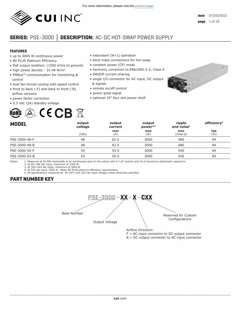
SERIES: PSE-3000 │ DESCRIPTION: AC-DC HOT-SWAP POWER SUPPLY
MODEL output voltage
output current
output power2,3
ripple and noise1
efficiency4
(Vdc)max(A)
max(W)
max(mVp-p)
typ(%)
PSE-3000-48-F 48 62.5 3000 480 94
PSE-3000-48-B 48 62.5 3000 480 94
PSE-3000-54-F 54 55.5 3000 540 94
PSE-3000-54-B 54 55.5 3000 540 94Notes: 1. Measured at 20 MHz bandwidth at an oscilloscope jack on the output with 0.1 µF ceramic and 10 µF aluminum electrolyitc capacitors. 2. At 90~180 Vac input, maximum of 1500 W. 3. At 180~264 Vac input, maximum of 3000 W. 4. At 230 Vac input, 3000 W. Meets 80 PLUS platinum efficiency requirements. 5. All specifications measured at: Ta=25°C and 220 Vac input voltage unless otherwise specified.
FEATURES• up to 3000 W continuous power• 80 PLUS Platinum Efficiency• PoE output isolation; (1500 Vrms to ground)• high power density - 33.48 W/in3
• PMBusTM communication for monitoring & control• dual fan forced cooling with speed control• front to back (-F) and back to front (-B) airflow versions• power factor correction• 3.3 Vdc (2A) standby voltage
• redundant (N+1) operation• blind mate connections for hot-swap• constant power (CP) mode• harmonic correction to EN61000-3-2, Class A• DROOP current sharing• single I/O connector for AC input, DC output & signals• remote on/off control• power good signal• optional 19” four slot power shelf
PART NUMBER KEY
Base Number Reserved for Custom Configurations
PSE-3000 - XX - X - CXX
Airflow Direction:F = AC input connector to DC output connectorB = DC output connector to AC input connector
Output Voltage
of N
or th America, Inc
.
TUV Rheinland
C US
For more information, please visit the product page.

cui.com
date 07/22/2015 │ page 2 of 19CUI Inc │ SERIES: PSE-3000 │ DESCRIPTION: AC-DC HOT-SWAP POWER SUPPLY
INPUTparameter conditions/description min typ max units
voltage 90 264 Vac
frequency 47 63 Hz
current at 90 Vac, 1500 Wat 180 Vac, full load
20.218.5
ArmsArms
inrush current at 115 Vac, cold startat 230 Vac, cold start
2040
AA
leakage current 1.5 mArms
power factor correction at 230 Vac, full load 0.99
OUTPUT - V1 (MAIN OUTPUT)parameter conditions/description min typ max units
line regulation ±3 %
load regulation ±3 %
load capacitance 30,000 μF
transient response 50% step load, 1A/µs slew rate, recovery to 1% within 1 ms 3 %
start-up time 5 s
hold-up time at 230 Vac, full load 12 ms
remote sense between both output terminals 0.5 V
current share accuracy (Droop) over 25% to 100% load ±10 %
LED indicator
AC OK: “green” to indicate AC above the lowerlimit that is required to sustain normal operation
DC OK: “green” to indicate module in normaloperating condition
OUTPUT - V2 (STANDBY OUTPUT)parameter conditions/description min typ max units
output voltage 3.3 Vdc
output current 0 2 A
ripple and noise1 33 mVp-p
line regulation ±5 %
load regulation ±5 %
load capacitance 1000 µF
transient response 50% step load, 1A/µs slew rate, recovery to 1% within 1 ms 3 %
start-up time 5 sNotes: 1. Measured at 20 MHz bandwidth at an oscilloscope jack on the output with 0.1 µF ceramic and 10 µF aluminum electrolyitc capacitors.
PROTECTIONSparameter conditions/description min typ max units
over voltage protection V1: latch offV2: latch off 110
60120
Vdc%
over current protection V1: constant current inceptionV2: hiccup
62.52.6
AA
over temperature protection at full load, auto recovery 55 °C
For more information, please visit the product page.
cui.com
date 07/22/2015 │ page 3 of 19CUI Inc │ SERIES: PSE-3000 │ DESCRIPTION: AC-DC HOT-SWAP POWER SUPPLY
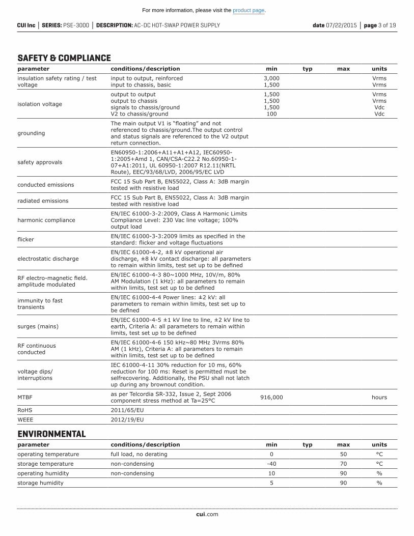
SAFETY & COMPLIANCEparameter conditions/description min typ max units
insulation safety rating / test voltage
input to output, reinforcedinput to chassis, basic
3,0001,500
VrmsVrms
isolation voltage
output to outputoutput to chassissignals to chassis/groundV2 to chassis/ground
1,5001,5001,500100
VrmsVrmsVdcVdc
grounding
The main output V1 is “floating” and not referenced to chassis/ground.The output control and status signals are referenced to the V2 output return connection.
safety approvals
EN60950-1:2006+A11+A1+A12, IEC60950-1:2005+Amd 1, CAN/CSA-C22.2 No.60950-1-07+A1:2011, UL 60950-1:2007 R12.11(NRTL Route), EEC/93/68/LVD, 2006/95/EC LVD
conducted emissions FCC 15 Sub Part B, EN55022, Class A: 3dB margin tested with resistive load
radiated emissions FCC 15 Sub Part B, EN55022, Class A: 3dB margin tested with resistive load
harmonic complianceEN/IEC 61000-3-2:2009, Class A Harmonic Limits Compliance Level: 230 Vac line voltage; 100% output load
flicker EN/IEC 61000-3-3:2009 limits as specified in the standard: flicker and voltage fluctuations
electrostatic dischargeEN/IEC 61000-4-2, ±8 kV operational air discharge, ±8 kV contact discharge: all parameters to remain within limits, test set up to be defined
RF electro-magnetic field. amplitude modulated
EN/IEC 61000-4-3 80~1000 MHz, 10V/m, 80% AM Modulation (1 kHz): all parameters to remain within limits, test set up to be defined
immunity to fasttransients
EN/IEC 61000-4-4 Power lines: ±2 kV: all parameters to remain within limits, test set up to be defined
surges (mains)EN/IEC 61000-4-5 ±1 kV line to line, ±2 kV line to earth, Criteria A: all parameters to remain within limits, test set up to be defined
RF continuousconducted
EN/IEC 61000-4-6 150 kHz~80 MHz 3Vrms 80% AM (1 kHz), Criteria A: all parameters to remain within limits, test set up to be defined
voltage dips/interruptions
IEC 61000-4-11 30% reduction for 10 ms, 60% reduction for 100 ms: Reset is permitted must be selfrecovering. Additionally, the PSU shall not latch up during any brownout condition.
MTBF as per Telcordia SR-332, Issue 2, Sept 2006component stress method at Ta=25°C 916,000 hours
RoHS 2011/65/EU
WEEE 2012/19/EU
ENVIRONMENTALparameter conditions/description min typ max units
operating temperature full load, no derating 0 50 °C
storage temperature non-condensing -40 70 °C
operating humidity non-condensing 10 90 %
storage humidity 5 90 %
For more information, please visit the product page.

cui.com
date 07/22/2015 │ page 4 of 19CUI Inc │ SERIES: PSE-3000 │ DESCRIPTION: AC-DC HOT-SWAP POWER SUPPLY
ENVIRONMENTAL (CONTINUED)parameter conditions/description min typ max units
acoustic ISO 7779-1999 60 dB LpAm
cold1 IEC 68 Part 2 – 1: at -10°C minimum for 4 hours
dry heat IEC 68 Part 2 – 2: at 50°C minimum for 4 hours
damp heat, cyclic IEC 68 Part 2 – 30: at 20~45°C, 30~95 %RH
low air pressure (operating) IEC 68 Part 2 – 13: at 10,000 feet, 697 mbar
vibration (sinusoidal)IEC 68 Part 2 – 6: at 10~58 Hz, 0.075 mm; 58~500 Hz, 10 m/s2, 1 octave/minute, 10 cycles/main axis
1 G
shock IEC 68 Part 2 – 27: at 300 m/s2, 11 ms, half sine wave 3 shocks/main axis 30 G
bump IEC 68 Part 2 – 29: at 150 m/s2, 6 ms, half sine wave 900 bumps/main axis 15 G
Notes: 1. The module shall start up at -10°C, however it is not required that the full specification is achieved until the operational internal temperature has risen to 0°C.
MECHANICALparameter conditions/description min typ max units
dimensions 14.00 x 4.00 x 1.60 (355.6 x 101.6 x 40.6 mm) inches
weight 2.01 kg
cooling / airflow integral fans
material flammability UL 94V-0
AC input IEC320/C14
DC output FCI PwrBlade P/N 51939-661LFmates with FCI P/N 51915-351LF
MECHANICAL DRAWING
A1 A4A3A2 A6A5B1 B4B3B2 B6B5
C1 C4C3C2 C6C5D1 D4D3D2 D6D5
P1 P2 P4P3 P6P5 P9P8P7
units: inches [mm]tolerance:X.XX ±0.02 [0.50]X.XXX ±0.010 [0.25]
For more information, please visit the product page.

cui.com
date 07/22/2015 │ page 5 of 19CUI Inc │ SERIES: PSE-3000 │ DESCRIPTION: AC-DC HOT-SWAP POWER SUPPLY
PIN FUNCTION DESCRIPTION HIGH / LOW LEVEL Imax
P1, P2, P3 V (-VE/return) V1 (-VE) output terminal
P4, P5, P6 V (+VE) V1 (+VE) output terminal
P7 earth/chassis ground protective/safety earth
P8 neutral neutral or AC line#2
P9 line hot/AC line#1
signal pin
column “1”
A1 I2C address A0 I2C address - LSB
B1 I2C address A1 I2C address bit
C1 I2C address A2 I2C address - MSB
D1 REMOTE_ON_L
internal pull up to 3.3 V
3.3 mA
signal pin status output status
open circuit “off”
logic “1” “off”
logic “0” “on”
signal pin
column “2”
A2 DC_OK_L
“L” to indicate DC output is within regulation, there is no internal pull up resistor and it should
be provided externally to support VCEO ≤ 20 Vdc, Ic ≤ 5 mA dc
>2.1 V<0.4 V -5 mA
B2 AC_OK_L
“L” to indicate AC above lower limit that is required for sustain normal operation, there is no internal
pull up resistor and it should be provided externally to support VCEO ≤ 20 Vdc, Ic ≤ 5 mA dc
>2.1 V<0.4 V -5 mA
C2 PS_PRESENT_Ldetects presence of power supply, “low” when
inserted, host system to provide pull up resistor capable of sourcing 5 mA
>2.1 V<0.4 V -5 mA
D2 Vstandby (+VE) V2 (+VE) output terminal
signal pin
column “3”
A3 I2C/SMbus clock external 3.32 kΩ pull-up needed to 3.3 V -3 mA
B3 I2C/SMbus data external 3.32 kΩ pull-up needed to 3.3 V -3 mA
C3 SMBALERT communications (SMBus) alert >2.1 V<0.4 V -5 mA
D3 Vstandby (-VE) V2 (-VE) output terminal
signal pin
column “4”
A4 n/a reserved
B4 n/a reserved
C4 OTP_OK_L temperature “OK” signal >2.1 V<0.4 V -5 mA
D4 n/a reserved
signal pin
column “5”
A5 Spare/Vpgm analog VPGM signal
B5 n/a reserved
C5 n/a reserved
D5 n/a reserved
signal pin
column “6”
A6 V1 -VE sense V1 negative sense connection
B6 Ishare V1 current share option
C6 n/a reserved
D6 V1 +VE sense V1 positive sense connection
DC PIN ASSIGNMENTS
For more information, please visit the product page.

cui.com
date 07/22/2015 │ page 6 of 19CUI Inc │ SERIES: PSE-3000 │ DESCRIPTION: AC-DC HOT-SWAP POWER SUPPLY
APPLICATION NOTESDigital Communication Feature SetThe default method of digital communication shall utilize I2C hardware capable of operation at a minimum of 100 kHz clock (SCL) frequency. A mandatory feature of this module is that should either the module be disconnected from the incoming AC source (inserted in to a slot in an unpowered state); the module input fuse(s) fail; or the internal auxiliary supply (which derives the VCC of the I2C equipped device) fail, then any line associated with the I2C bus (SCL; SDA) should be disconnected (effectively tri-stated) from the I2C bus to prevent erroneous operation that may result from this unpowered condition. All I2C lines shall be “clean” and free from excessive spikes and common mode noise and comply with the requirements of the generic standard which defines I2C logic levels.
The I2C hardware should conform to the requirements of the NXP (formerly Philips Semiconductor) Standard: UM10204 I2C Bus Specification and User Manual; Rev 0.3; 19 June 2007.
The rectifier shall be capable of processing commands to monitor & control the rectifier via the digital bus by use of the following protocols:
• CUI’s “standard” protocol – this shall be considered the “default” that shall be offered as a standard. • The PMBusTM (Power Management Bus) Protocol – this shall be considered the “optional” offering.
I2C “Standard” FeatureThe following features will be offered as “standard” by the base product:
Vital Product Data (VPD)This feature shall provide write-protected Vital Product Data (VPD) which shall include the following:
• Revision level • CUI Date Code and origin of manufacture • CUI Serial number (from the product label) is the last 5 or 6 maximum numbers, and is padded with zeros to fit the PMBusTM variable as 8 bytes total
Slave AddressesThe product’s 7-bit I2C slave address is formed by determining the logic state of the address pins A0, A1 and A2. A pull-up resistor shall be supplied within the product for each address pin. The values of A0, A1 and A2 are set in the backplane of the system. Thus the device can be set to respond to all 7-bit addresses in the range from binary 1011 000 to 1011 111.
The address pins shall be read once the micro-controllers have been initialized. To prevent hot swapping from latching the slave address to a specific slot in the enclosure, the software shall continuously read and update at an interval of 1 s the slave address accordingly.
Bit 7 Bit 6 Bit 5 Bit 4 Bit 3 Bit 2 Bit 1 Bit 0
1 0 1 1 A2 A1 A0 R/W
For more information, please visit the product page.
cui.com
date 07/22/2015 │ page 7 of 19CUI Inc │ SERIES: PSE-3000 │ DESCRIPTION: AC-DC HOT-SWAP POWER SUPPLY
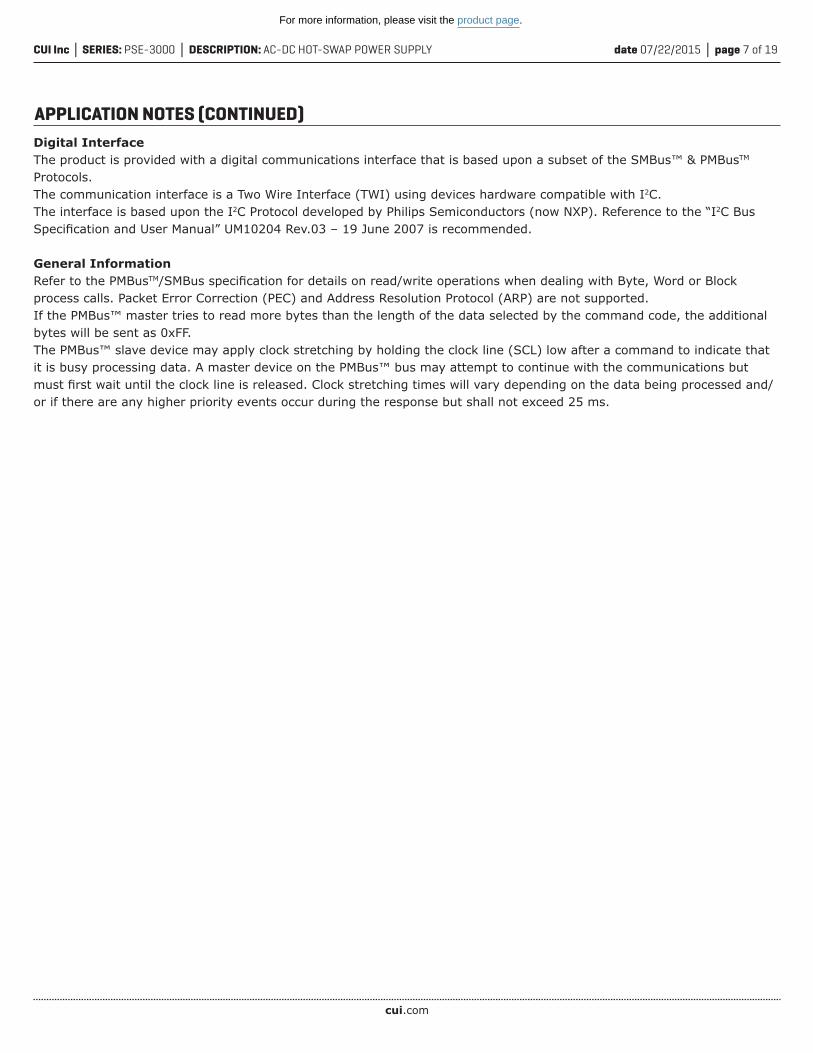
APPLICATION NOTES (CONTINUED)Digital InterfaceThe product is provided with a digital communications interface that is based upon a subset of the SMBus™ & PMBusTM
Protocols.The communication interface is a Two Wire Interface (TWI) using devices hardware compatible with I2C. The interface is based upon the I2C Protocol developed by Philips Semiconductors (now NXP). Reference to the “I2C Bus Specification and User Manual” UM10204 Rev.03 – 19 June 2007 is recommended.
General InformationRefer to the PMBusTM/SMBus specification for details on read/write operations when dealing with Byte, Word or Block process calls. Packet Error Correction (PEC) and Address Resolution Protocol (ARP) are not supported.If the PMBus™ master tries to read more bytes than the length of the data selected by the command code, the additional bytes will be sent as 0xFF.The PMBus™ slave device may apply clock stretching by holding the clock line (SCL) low after a command to indicate that it is busy processing data. A master device on the PMBus™ bus may attempt to continue with the communications but must first wait until the clock line is released. Clock stretching times will vary depending on the data being processed and/or if there are any higher priority events occur during the response but shall not exceed 25 ms.
For more information, please visit the product page.

cui.com
date 07/22/2015 │ page 8 of 19CUI Inc │ SERIES: PSE-3000 │ DESCRIPTION: AC-DC HOT-SWAP POWER SUPPLY
APPLICATION NOTES (CONTINUED)PMBus™ COMMAND SUBSETThe following is subset of commands (extracted from the “PMBus™ Power System Management Protocol Specification; Part II Command Language; Rev 1.2, 6 September 2010”) and apply on a per module basis, (although certain commands could be applied “globally”). For a full definition of the individual command refer to the above referenced PMBusTM specification.
Opcode(HEX)
CommandName
No. ofBytes Type Read /
Write Command Description
01 OPERATION 1 Byte W The OPERATION command is used to turn the unit on & off inconjunction with the CONTROL (short; last make, first make pin).
03 CLEAR_FAULTS 0 N/A W Clear fault data latched at STATUS_WORD
19 CAPABILITY 1 Byte R Follows PMBus™ spec.
78 STATUS_BYTE 1 Byte R Lower byte returned from the STATUS_WORD
79 STATUS_WORD 2 Word R The command returns two bytes of data relating to the unitfault condition.
88 READ_VIN 2 Word R Provides the measured input voltage of the power module.(Divide decimal value by 100)
89 READ_IIN 2 Word R Provides the measured input current of the power module.(Divide decimal value by 100)
8B READ_VOUT 2 Word R Provides the measured output voltage of the power module.(Divide decimal value by 100)
8C READ_IOUT 2 Word R Provides the measured output current of the power module.(Divide decimal value by 100)
8D READ_TEMPERATURE_1 2 Word R This command shall return the prevailing internal ambient of thepower module, in degrees Celsius.
8E READ_TEMPERATURE_2 2 Word R This command shall return a select component temperature usedby the power module, in degrees Celsius.
8F READ_TEMPERATURE_3 2 Word R This command shall return a select component temperature usedby the power module, in degrees Celsius.
90 READ_FAN_SPEED_1 2 Word R Provides the measured fan speed (RPM) in the power module.
91 READ_FAN_SPEED_2 2 Word R Provides the measured fan speed (RPM) in the power module.
96 READ_POUT 2 Word R This command shall return the calculated output being deliveredby the power module, in Watts. (Divide value by 10)
97 READ_PIN 2 Word R This command shall return the calculated input being drawn bythe power module, in Watts. (Divide value by 10)
98 PMBusTM_REVISION 1 Byte R PMBus™ Revision
99 MFR_ID 8 Block R The command returns the ASCII string for manufacturer’s ID.
9A MFR_MODEL 12 Block R The command returns the ASCII string manufacturer’s model.
9B MFR_REVISION 2 Block R The command returns the ASCII string manufacturer’s revision(example case “A0”).
9C MFR_LOCATION 8 Block R The command returns the ASCII string manufacturer’s revision(example case “TORONTO”).
9D MFR_DATE 4 Block R The command returns the ASCII string manufacturer’s date code(example case “0913”).
9E MFR_SERIAL 8 Block R The command returns manufacturers serial number.
For more information, please visit the product page.

cui.com
date 07/22/2015 │ page 9 of 19CUI Inc │ SERIES: PSE-3000 │ DESCRIPTION: AC-DC HOT-SWAP POWER SUPPLY
APPLICATION NOTES (CONTINUED)PMBus™ Non-Standard Extended Command Subset
Remote On/Off (PMBus™Operation Command 0x01)This command can be used to turn the unit on and off via the PMBus™ interface.If D1 (REMOTE_ENABLE) is LOW (enabled) then the PMBus™ Remote On/Off function can turn the unit off and on. If D1(REMOTE_ENABLE) is HIGH (disabled) then the PMBus™ Remote On/Off function cannot turn the unit on or off and can be ignored.The bit encoding of the data byte of the command is as follows.
Opcode(HEX)
CommandName
No. ofBytes Type Read /
Write Command Description
16 FIRMWARE_REVISION 4 Block R Read vendor specific firmware revision (ASCII string). Examplecase “A100”
17 BUILD 4 Block R Read vendor specific Build (ASCII string)
20 AUXILIARY_VOLTAGE 2 Word R Provides the measured output auxiliary voltage of the powermodule. (Divide decimal value by 100)
8D READ_TEMPERATURE_4 2 Word R This command shall return a select component temperature usedby the power module, in degrees Celsius.
8E READ_TEMPERATURE_5 2 Word R This command shall return a select component temperature usedby the power module, in degrees Celsius.
Bits [7:6] Bits [5:4] Bits [3:2] Bits [1:0] Unit State
00 XX XX XX Off
01 XX XX XX Off
10 00 XX XX On
10 01 00 XX No change
10 01 11 XX No change
10 01 01 XX On
10 01 10 XX On
10 10 01 XX On
10 10 10 XX On
10 10 11 XX No change
10 11 XX XX No change
11 XX XX XX No change
For more information, please visit the product page.
cui.com
date 07/22/2015 │ page 10 of 19CUI Inc │ SERIES: PSE-3000 │ DESCRIPTION: AC-DC HOT-SWAP POWER SUPPLY
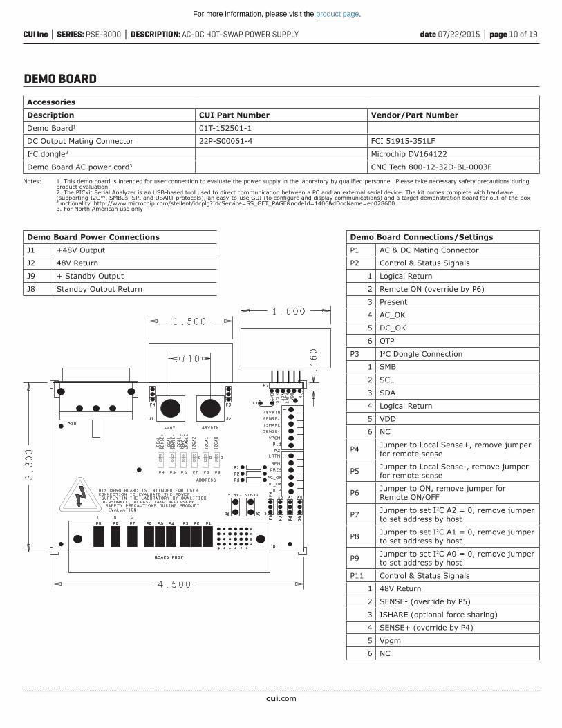
DEMO BOARD
Notes: 1. This demo board is intended for user connection to evaluate the power supply in the laboratory by qualified personnel. Please take necessary safety precautions during product evaluation. 2. The PICkit Serial Analyzer is an USB-based tool used to direct communication between a PC and an external serial device. The kit comes complete with hardware (supporting I2C™, SMBus, SPI and USART protocols), an easy-to-use GUI (to configure and display communications) and a target demonstration board for out-of-the-box functionality. http://www.microchip.com/stellent/idcplg?IdcService=SS_GET_PAGE&nodeId=1406&dDocName=en028600 3. For North American use only
Accessories
Description CUI Part Number Vendor/Part Number
Demo Board1 01T-152501-1
DC Output Mating Connector 22P-S00061-4 FCI 51915-351LF
I2C dongle2 Microchip DV164122
Demo Board AC power cord3 CNC Tech 800-12-32D-BL-0003F
Demo Board Power Connections
J1 +48V Output
J2 48V Return
J9 + Standby Output
J8 Standby Output Return
Demo Board Connections/Settings
P1 AC & DC Mating Connector
P2 Control & Status Signals
1 Logical Return
2 Remote ON (override by P6)
3 Present
4 AC_OK
5 DC_OK
6 OTP
P3 I2C Dongle Connection
1 SMB
2 SCL
3 SDA
4 Logical Return
5 VDD
6 NC
P4 Jumper to Local Sense+, remove jumper for remote sense
P5 Jumper to Local Sense-, remove jumper for remote sense
P6 Jumper to ON, remove jumper for Remote ON/OFF
P7 Jumper to set I2C A2 = 0, remove jumper to set address by host
P8 Jumper to set I2C A1 = 0, remove jumper to set address by host
P9 Jumper to set I2C A0 = 0, remove jumper to set address by host
P11 Control & Status Signals
1 48V Return
2 SENSE- (override by P5)
3 ISHARE (optional force sharing)
4 SENSE+ (override by P4)
5 Vpgm
6 NC
For more information, please visit the product page.

cui.com
date 07/22/2015 │ page 11 of 19CUI Inc │ SERIES: PSE-3000 │ DESCRIPTION: AC-DC HOT-SWAP POWER SUPPLY
POWER SHELF
Power ShelfModel Number
Power ModuleModel Number
AirflowDirection
Shelf Power StandbyOutput
IEC Inlet Type110 Vin 220 Vin
PPR-1U PSE-3000-48-F or PSE-3000-54-F Front to Back 6,000 W 12,000 WAll Parallel,dual polarityterminal block
C22
PPR-1U-A PSE-3000-48-F or PSE-3000-54-F Front to Back 6,000 W 12,000 WA & B Feed,dual polarityterminal block
C22
PPR-1U-B PSE-3000-48-B or PSE-3000-54-B Back to Front 5,400 W 12,000 WAll Parallel,dual polarityterminal block
C20
PPR-1U-C PSE-3000-48-B or PSE-3000-54-B Back to Front 5,400 W 12,000 WA & B Feed,dual polarityterminal block
C20
PPR-1U-D PSE-3000-48-F or PSE-3000-54-F Front to Back 6,000 W 12,000 WAll Parallel,single polarityterminal block
C22
PPR-1U-E PSE-3000-48-B or PSE-3000-54-B Back to Front 5,400 W 12,000 WAll Parallel,single polarityterminal block
C20
PPR-1U, PPR-1U-A, PPR-1U-D - FRONT TO BACK AIRFLOW
PPR-1U-B, PPR-1U-C, PPR-1U-E - BACK TO FRONT AIRFLOW
For more information, please visit the product page.

cui.com
date 07/22/2015 │ page 12 of 19CUI Inc │ SERIES: PSE-3000 │ DESCRIPTION: AC-DC HOT-SWAP POWER SUPPLY
POWER SHELF (CONTINUED)PPR-1U, PPR-1U-A, PPR-1U-D - FRONT TO BACK AIRFLOW
For more information, please visit the product page.
cui.com
date 07/22/2015 │ page 13 of 19CUI Inc │ SERIES: PSE-3000 │ DESCRIPTION: AC-DC HOT-SWAP POWER SUPPLY
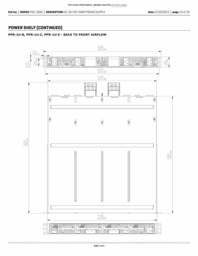
POWER SHELF (CONTINUED)PPR-1U-B, PPR-1U-C, PPR-1U-E - BACK TO FRONT AIRFLOW
For more information, please visit the product page.

cui.com
date 07/22/2015 │ page 14 of 19CUI Inc │ SERIES: PSE-3000 │ DESCRIPTION: AC-DC HOT-SWAP POWER SUPPLY
POWER SHELF (CONTINUED)PPR-1U & PPR-1U-B Output Terminal Block Configuration
All 4 power modules wired in parallel inside the power shelf, 12 kW available from each output
PPR-1U-A & PPR-1U-C Output Terminal Block Configuration
Each terminalblock wired to 2 power modules, 6 kW available from each output
PPR-1U-D & PPR-1U-E Output Terminal Block Configuration
All 4 power modules wired in parallel inside the power shelf, one single output through both terminal block, 12 kWavailable from each output
+-
+-
+-
+-
++
--
For more information, please visit the product page.
cui.com
date 07/22/2015 │ page 15 of 19CUI Inc │ SERIES: PSE-3000 │ DESCRIPTION: AC-DC HOT-SWAP POWER SUPPLY
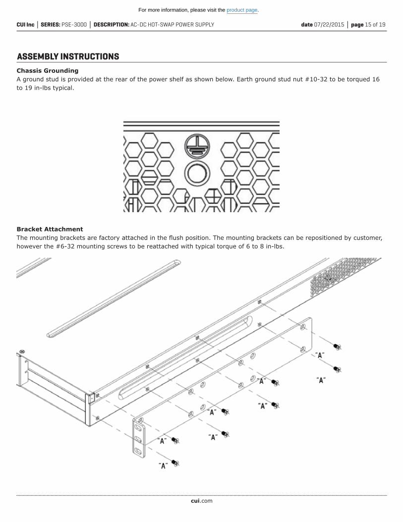
ASSEMBLY INSTRUCTIONSChassis GroundingA ground stud is provided at the rear of the power shelf as shown below. Earth ground stud nut #10-32 to be torqued 16 to 19 in-lbs typical.
Bracket AttachmentThe mounting brackets are factory attached in the flush position. The mounting brackets can be repositioned by customer, however the #6-32 mounting screws to be reattached with typical torque of 6 to 8 in-lbs.
For more information, please visit the product page.

cui.com
date 07/22/2015 │ page 16 of 19CUI Inc │ SERIES: PSE-3000 │ DESCRIPTION: AC-DC HOT-SWAP POWER SUPPLY
ASSEMBLY INSTRUCTIONS (CONTINUED)Output Cable ConnectionThe Output and Return Cables (#2 AWG wire on 1/4” slud - not provided) to be A ground stud is provided at the rearof the power shelf as shown below.Earth ground stud nut #10-32 to be torqued 16 to 19 in-lbs typical.
AC Line Cord ConnectionThe power shelf is not shipped with AC line cords and the customer is responsible to provide its own AC line cords tomeet the respective local electrical code requirements.
For more information, please visit the product page.

cui.com
date 07/22/2015 │ page 17 of 19CUI Inc │ SERIES: PSE-3000 │ DESCRIPTION: AC-DC HOT-SWAP POWER SUPPLY
ASSEMBLY INSTRUCTIONS (CONTINUED)
Slot 1 Slot 2 Slot 3 Slot 4
A2 Address SwitchAddress
Slot 1 Slot 2 Slot 3 Slot 4
DOWN 000 001 010 011
UP 100 101 110 111
For more information, please visit the product page.

cui.com
date 07/22/2015 │ page 18 of 19CUI Inc │ SERIES: PSE-3000 │ DESCRIPTION: AC-DC HOT-SWAP POWER SUPPLY
ASSEMBLY INSTRUCTIONS (CONTINUED)
D-Sub 9 I2C communicationThe 2 D-Sub connector signals are parallel inside the power shelf
A2 AddressSwitchV Standby Output
Connector
V Standby Output Connector, Mating Connector Molex 39-01-2020, terminals 39-00-0038
Connector - Pin# Signal Name Function
1 (lower position) +3.3 STANDBY +3.3 VDC +VE Output
2 (upper position) +3.3 STANDBY RTN +3.3 VDC –VE Output
System Interface Connection D sub 9 pin (female) System to Shelf Shelf to Shelf
SDA 1 Yes Yes
SCL 2 Yes Yes
Not used 3
Vpgm 4 Yes Yes
Vpgm Return 5 Yes Yes
Digital Return 6 Yes Yes
SMB Alert 7 Yes Yes
Not used 8
I-Share 9 Yes Yes
A2 Address Switch, UP position for “1”, DOWN position for “0”
Notes: 1. The PICkit Serial Analyzer is an USB-based tool used to direct communication between a PC and an external serial device. The kit comes complete with hardware (supporting I2C™, SMBus, SPI and USART protocols), an easy-to-use GUI (to configure and display communications) and a target demonstration board for out-of-the-box functionality.
Accessories
Description CUI Part Number Vendor/Part Number
D-Sub 9 male to male cable Assmann WSW Components AK174-3
Vstandby Output Mating Connector Molex 39-01-2020
I2C dongle1 Microchip DV164122
I2C dongle to D sub 9 cable 014-157401-4
For more information, please visit the product page.

date 07/22/2015 │ page 19 of 19CUI Inc │ SERIES: PSE-3000 │ DESCRIPTION: AC-DC HOT-SWAP POWER SUPPLY
CUI offers a two (2) year limited warranty. Complete warranty information is listed on our website.
CUI reserves the right to make changes to the product at any time without notice. Information provided by CUI is believed to be accurate and reliable. However, no responsibility is assumed by CUI for its use, nor for any infringements of patents or other rights of third parties which may result from its use.
CUI products are not authorized or warranted for use as critical components in equipment that requires an extremely high level of reliability. A critical component is any component of a life support device or system whose failure to perform can be reasonably expected to cause the failure of the life support device or system, or to affect its safety or effectiveness.
Headquarters20050 SW 112th Ave.Tualatin, OR 97062800.275.4899
rev. description date
1.0 initial release 05/07/20151.01 updated datasheet 06/11/20151.02 updated datasheet 07/22/2015
The revision history provided is for informational purposes only and is believed to be accurate.
REVISION HISTORY
For more information, please visit the product page.