ac 150/5220-21c, aircraft boarding equipment, 29 june 2012
TRANSCRIPT

U.S. Department
of Transportation
Federal Aviation
Administration
Advisory
Circular Subject: Aircraft Boarding Equipment Date: 6/29/2012
Initiated by: AAS-100
AC No: 150/5220-21C
Change:
1. PURPOSE. This advisory circular (AC) contains the Federal Aviation Administration’s (FAA’s)
performance standards, specifications, and recommendations for the design, manufacture, testing and
maintenance of equipment used in the boarding of airline passengers.
2. CANCELLATION. This AC cancels AC 150/5220-21B, Guide Specification for Devices Used
to Board Airline Passengers with Mobility Impairments, dated March 17, 2000.
3. SCOPE. This AC covers the four most common pieces of equipment used to board aircraft:
a. Passenger boarding bridges (PBBs) that are entered from the passenger terminal boarding
area,
b. Ramps that are moved into place to allow boarding from the airport apron,
c. Lifts to vertically transport passengers from the airport apron to the door of the aircraft, and
d. Aircraft boarding chairs used to transfer passengers from their wheelchair or other apparatus
to their seat in the aircraft cabin.
The physical area covered in this AC is that which is bounded by the door of the passenger terminal area,
on one end, to the door of the aircraft, on the other end. Although this AC refers only to aircraft boarding
(enplaning), all references apply equally to disembarking (deplaning) with the described procedures
occurring in reverse order.
Chapters 3-5 for this AC are primarily based on the performance standards, specifications, and
recommendations contained in the Society of Automotive Engineers (SAE) Aerospace Recommended
Practice (ARP) 1247, General Requirements for Aerospace Ground Support Equipment (Motorized and
Non-motorized), U.S. Access Board’s Technical Assistance Manual for ADA Accessibility Guidelines
(ADAAG) for Transportation Vehicles (September 1998), and ADA and ABA Accessibility Guidelines
for Buildings and Facilities (Published in the Federal Register July 23, 2004 and amended August 5,
2005). Chapter 6 of this AC is based on the U.S. Access Board Technical Paper on Guidelines for
Aircraft Boarding Chairs. Additional requirements and clarifications have been added where necessary.
The Department of Justice issued 28 CFR Part 36, adopting enforceable accessibility standards under the
ADA consistent with the minimum guidelines and requirements of the United States Architectural and
Transportation Barriers Compliance Board (Access Board). The rule at 28 CFR Part 36 adopts the Access
Board guidelines found at 36 CFR Part 1191, Appendix D (2009), and these guidelines now have legal
effect. Accordingly, all references to 36 CFR Part 1191, Appendix D (2009) throughout this AC, are
codified at 28 CFR Part 36.
AC 150/5220-21C 6/29/2012
ii
Pertinent FAA AC, U.S. Access Board, Military Standards and non-government industry standards are
also referenced (see Appendix C for more information) and, in the event of a conflict between the text of
this document and the references cited herein, the text of this document takes precedence.
In addition to general design guidance, areas that may require clarification or tailoring in purchasing
PBBs, ramps, lift and boarding chairs to suit the needs of specific airports are contained in tables at the
end of each of their respective chapters.
4. APPLICATION. The Federal Aviation Administration recommends the use of the guidance in
this publication for the preparation of specifications for devices to assist in the boarding of passengers
with mobility impairments.
Equipment meeting the specifications provided in this circular satisfies the boarding device requirements
contained in U.S. Department of Transportation regulations 49 CFR Part 27, Nondiscrimination on the
Basis of Disability in Programs or Activities Receiving Federal Financial Assistance, paragraph 27.72,
and 14 CFR Part 382, Nondiscrimination on the Basis of Disability in Air Travel, subpart G – Boarding,
Deplaning, and Connecting Assistance, paragraphs 382.91 through 382.105.
The use of this AC is a means of fulfilling the applicable mandatory requirements set out in Airport
Improvement Program (AIP) grant assurances, Passenger Facility Charge (PFC) assurances, and
regulations; alternate means of satisfying these requirements which are in accordance with applicable
laws and regulations are acceptable.
5. PRINCIPAL CHANGES. The previous version of this AC discussed only the passenger lift
scenario and associated equipment. This document updates that effort while also addressing the other
methods and equipment used to board an aircraft.
6. COMMENTS OR SUGGESTIONS for improvements to this AC should be sent to:
Manager, Airport Engineering Division
Federal Aviation Administration
ATTN: AAS-100
800 Independence Avenue, S.W.
Washington, DC 20591
Michael J. O'Donnell
Director of Airport Safety and Standards
6/29/2012 AC 150/5220-21C
iii
TABLE OF CONTENTS
CHAPTER 1. INTRODUCTION ................................................................................................ 1 1.1. GENERAL. ................................................................................................................................... 1 1.2. PERSONS WITH DISABILITIES. .............................................................................................. 1
CHAPTER 2. FUNDAMENTAL STANDARDS. ...................................................................... 3 2.1. GENERAL. ................................................................................................................................... 3 2.2. DESIGN STANDARDS. .............................................................................................................. 3 2.3. OPERATIONAL STANDARDS. ................................................................................................. 8 2.4. INSTALLATION AND ACCEPTANCE STANDARDS. ......................................................... 11 2.5. POST-DELIVERY STANDARDS. ............................................................................................ 13 2.6 PURCHASING SPECIFICATION CLARIFICATIONS. .......................................................... 14
CHAPTER 3. PASSENGER BOARDING BRIDGES (PBBs) ............................................... 15 3.1. GENERAL. ................................................................................................................................. 15 3.2. SYSTEM DESCRIPTION. ......................................................................................................... 15 3.3. SYSTEM COMPONENTS. ........................................................................................................ 15 3.4. PERFORMANCE. ...................................................................................................................... 16 3.5. DESIGN / DEVELOPMENT PHASE. ....................................................................................... 18 3.6. CONSTRUCTION / PRODUCTION PHASE. .......................................................................... 28 3.7. POST-PRODUCTION PHASE. ................................................................................................. 31 3.8. PURCHASING SPECIFICATION CLARIFICATIONS. .......................................................... 33
CHAPTER 4. RAMPS ................................................................................................................ 35 4.1. GENERAL. ................................................................................................................................. 35 4.2. SYSTEM DESCRIPTION. ......................................................................................................... 35 4.3. SYSTEM COMPONENTS. ........................................................................................................ 36 4.4. PERFORMANCE. ...................................................................................................................... 37 4.5. DESIGN / DEVELOPMENT PHASE. ....................................................................................... 38 4.6. CONSTRUCTION / PRODUCTION PHASE. .......................................................................... 41 4.7. POST-PRODUCTION PHASE. ................................................................................................. 41 4.8. PURCHASING SPECIFICATION CLARIFICATIONS. .......................................................... 42
CHAPTER 5. LIFTS .................................................................................................................. 43 5.1. GENERAL. ................................................................................................................................. 43 5.2. SYSTEM DESCRIPTION. ......................................................................................................... 43 5.3. SYSTEM COMPONENTS. ........................................................................................................ 43 5.4. PERFORMANCE. ...................................................................................................................... 43 5.5. DESIGN / DEVELOPMENT PHASE. ....................................................................................... 45 5.6. CONSTRUCTION / PRODUCTION PHASE. .......................................................................... 49 5.7. POST-PRODUCTION PHASE. ................................................................................................. 49 5.8. PURCHASING SPECIFICATION CLARIFICATIONS. .......................................................... 50
CHAPTER 6. AIRCRAFT BOARDING CHAIRS ................................................................. 51 6.1. GENERAL. ................................................................................................................................. 51 6.2. PERFORMANCE. ...................................................................................................................... 51 6.3. DESIGN / DEVELOPMENT PHASE. ....................................................................................... 52 6.4. CONSTRUCTION / PRODUCTION PHASE. .......................................................................... 53

AC 150/5220-21C 6/29/2012
iv
6.5. POST-PRODUCTION PHASE. ................................................................................................. 54 6.6. PURCHASING SPECIFICATION CLARIFICATIONS. .......................................................... 54
APPENDIX A. ABBREVIATIONS AND ACRONYMS ....................................................... 55
APPENDIX B. GLOSSARY ..................................................................................................... 57
APPENDIX C. APPLICABLE DOCUMENTS ...................................................................... 59
APPENDIX D. ANNOTATED BIBLIOGRAPHY ................................................................. 63
LIST OF FIGURES
Figure 1. Clear Floor / Platform Space ........................................................................................................ 3 Figure 2. Clear Pathway Dimensions ........................................................................................................... 4 Figure 3. Carpet Pile Height ........................................................................................................................ 4 Figure 4. Vertical Change in Level (cross section) ...................................................................................... 5 Figure 5. Slope Changes .............................................................................................................................. 6 Figure 6. Ramp Dimensions ........................................................................................................................ 7 Figure 7. Basic Passenger Boarding Bridge (PBB) ................................................................................... 15 Figure 8. Ramps ......................................................................................................................................... 36
LIST OF TABLES
Table 1. Purchasing Specification Clarifications ....................................................................................... 14
Table 2. Passenger Boarding Bridge (PBB) Code Requirements. ............................................................. 30 Table 3. PBB Purchasing Specification Clarifications .............................................................................. 33 Table 4. Ramp Purchasing Specification Clarifications ............................................................................ 42 Table 5. Lift Purchasing Specification Clarifications ................................................................................ 50 Table 6. Aircraft Boarding Chair Purchasing Specification Clarifications ................................................ 54
6/29/2012 AC 150/5220-21C
1
CHAPTER 1. INTRODUCTION
1.1. GENERAL.
A fundamental goal of this AC is to promote the simple, fast, and dignified boarding of all passengers
regardless of their physical, sensory, or cognitive capabilities through the use performance standards,
specifications, and recommendations for aircraft boarding equipment.
NOTE: The Department of Justice issued 28 CFR Part 36, adopting enforceable
accessibility standards under the ADA consistent with the minimum guidelines and
requirements of the Access Board. The rule at 28 CFR Part 36 adopts the Access Board
guidelines found at 36 CFR Part 1191, Appendix D (2009), and these guidelines now have
legal effect. Accordingly, all references to 36 CFR Part 1191, Appendix D (2009)
throughout this AC, are codified at 28 CFR Part 36.
1.2. PERSONS WITH DISABILITIES.
a. The equipment in this advisory circular (AC) provides accommodations for a wide range of
passengers, including those with mobility, sensory, and cognitive impairments. It is important to
recognize that, for each of these types of disabilities, there exists a full range of characteristics. Mobility
impairments range from people that have difficulty walking due to use of a prosthetic to the high level
quadriplegic. Likewise, sensory impairments are on a continuous scale; most people with visual and
hearing impairments are not totally blind or deaf but may have a very limited range of visual or aural
stimuli that they can detect.
b. Understanding that all of the different disabilities include a wide range of severity is essential in
planning equipment that is appropriate for everyone. Many manifestations of a disability must be
considered so as not to leave out certain groups of individuals with mobility impairments. For example,
the typical reference made for “persons with mobility impairments” is that of wheelchair users. But
elderly passengers who walk with a shuffle must also be considered. As such, the importance of
handrails, level surfaces at transitions, and appropriate floor surfaces play a significant role in the overall
equipment design.
NOTE: For purposes of this document, the term “wheelchair” includes any wheeled mobility aid in
which a person sits - typically this includes scooters, manual chairs, and power chairs.
c. Universal Design. “Universal design” is a concept that aims to provide an equal level of service
to persons of all ages and abilities. As applied to the field of aviation, universal design is fundamental to
the safe and efficient transportation of the flying public. In keeping with the concept of universal design,
the overall philosophy of this document is to specify both the performance and design requirements that
enable seamless and integrated transportation options for all passengers.

AC 150/5220-21C 6/29/2012
2
This page intentionally left blank.
6/29/2012 AC 150/5220-21C
3
CHAPTER 2. FUNDAMENTAL STANDARDS
2.1. GENERAL.
Fundamental standards for aircraft boarding equipment are described in this chapter and include human
factors/human engineering, load capacity, dimensions, flooring, gaps and changes in levels, threshold
protection, and handrails.
2.2. DESIGN STANDARDS.
The standards contained in this section apply to all aircraft boarding equipment discussed in this AC.
Unless otherwise noted, the values represent the minimum allowable standards required to ensure access
to the majority of potential airline passengers.
a. Human Factors / Human Engineering. All boarding equipment must be easily operated by
personnel possessing no special skills and given minimum training on the equipment. Operation must
also be easily accomplished by personnel within the range of anthropomorphic sizes, as defined by the 5th
percentile Asian female on the lower limit, to the 95th percentile Caucasian male, on the upper limit.
Unless otherwise specified, and wherever applicable, the standards of Federal Aviation Administration
(FAA) HF-STD-001 must be followed.
b. Dimensions.
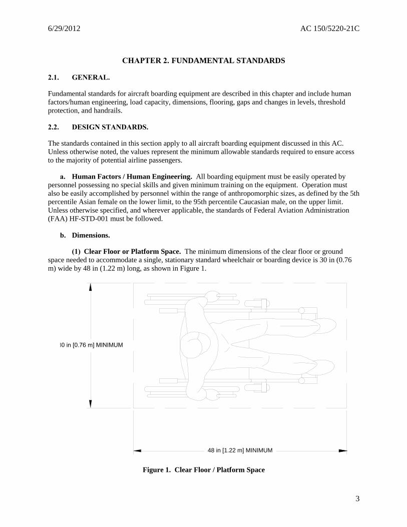
(1) Clear Floor or Platform Space. The minimum dimensions of the clear floor or ground
space needed to accommodate a single, stationary standard wheelchair or boarding device is 30 in (0.76
m) wide by 48 in (1.22 m) long, as shown in Figure 1.
48 in [1.22 m] MINIMUM
Figure 1. Clear Floor / Platform Space
AC 150/5220-21C 6/29/2012
4
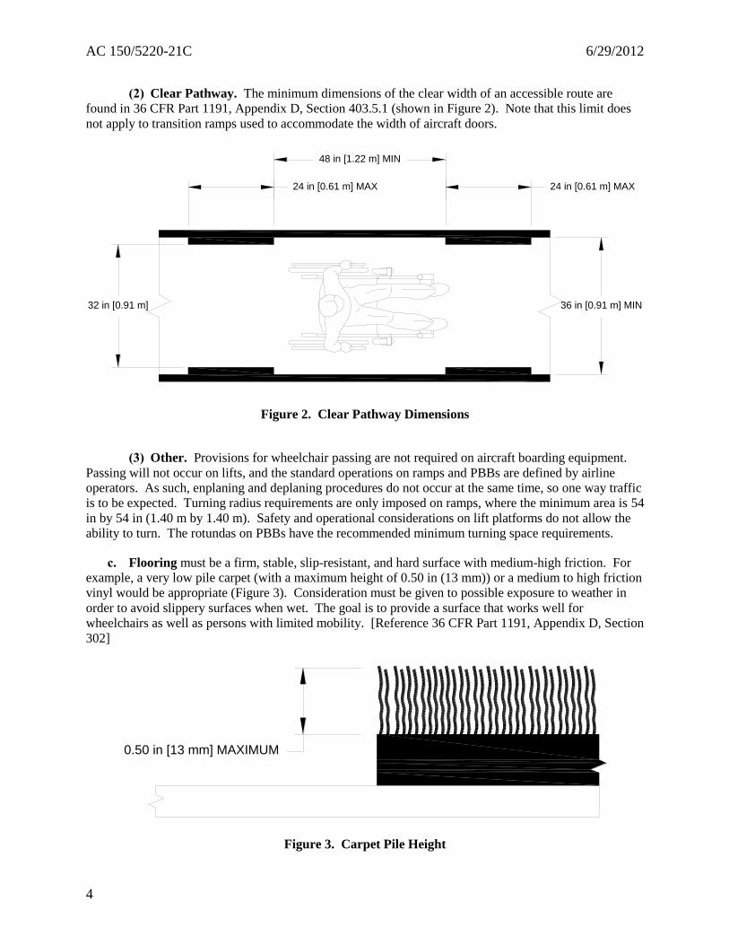
(2) Clear Pathway. The minimum dimensions of the clear width of an accessible route are
found in 36 CFR Part 1191, Appendix D, Section 403.5.1 (shown in Figure 2). Note that this limit does
not apply to transition ramps used to accommodate the width of aircraft doors.
36 in [0.91 m] MIN32 in [0.91 m]
48 in [1.22 m] MIN
24 in [0.61 m] MAX 24 in [0.61 m] MAX
Figure 2. Clear Pathway Dimensions
(3) Other. Provisions for wheelchair passing are not required on aircraft boarding equipment.
Passing will not occur on lifts, and the standard operations on ramps and PBBs are defined by airline
operators. As such, enplaning and deplaning procedures do not occur at the same time, so one way traffic
is to be expected. Turning radius requirements are only imposed on ramps, where the minimum area is 54
in by 54 in (1.40 m by 1.40 m). Safety and operational considerations on lift platforms do not allow the
ability to turn. The rotundas on PBBs have the recommended minimum turning space requirements.
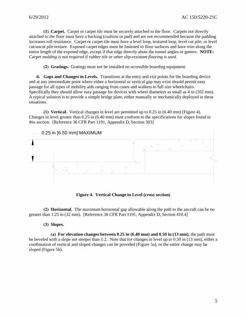
c. Flooring must be a firm, stable, slip-resistant, and hard surface with medium-high friction. For
example, a very low pile carpet (with a maximum height of 0.50 in (13 mm)) or a medium to high friction
vinyl would be appropriate (Figure 3). Consideration must be given to possible exposure to weather in
order to avoid slippery surfaces when wet. The goal is to provide a surface that works well for
wheelchairs as well as persons with limited mobility. [Reference 36 CFR Part 1191, Appendix D, Section
302]
0.50 in [13 mm] MAXIMUM
Figure 3. Carpet Pile Height
6/29/2012 AC 150/5220-21C
5
(1) Carpet. Carpet or carpet tile must be securely attached to the floor. Carpets not directly
attached to the floor must have a backing (cushion or pad) and are not recommended because the padding
increases roll resistance. Carpet or carpet tile must have a level loop, textured loop, level cut pile, or level
cut/uncut pile texture. Exposed carpet edges must be fastened to floor surfaces and have trim along the
entire length of the exposed edge, except if that edge directly abuts the tunnel angles or gutters. NOTE:
Carpet molding is not required if rubber tile or other slip-resistant flooring is used.
(2) Gratings. Gratings must not be installed on accessible boarding equipment.
d. Gaps and Changes in Levels. Transitions at the entry and exit points for the boarding device
and at any intermediate point where either a horizontal or vertical gap may exist should permit easy
passage for all types of mobility aids ranging from canes and walkers to full size wheelchairs.
Specifically they should allow easy passage for devices with wheel diameters as small as 4 in (102 mm).
A typical solution is to provide a simple bridge plate, either manually or mechanically deployed in these
situations.
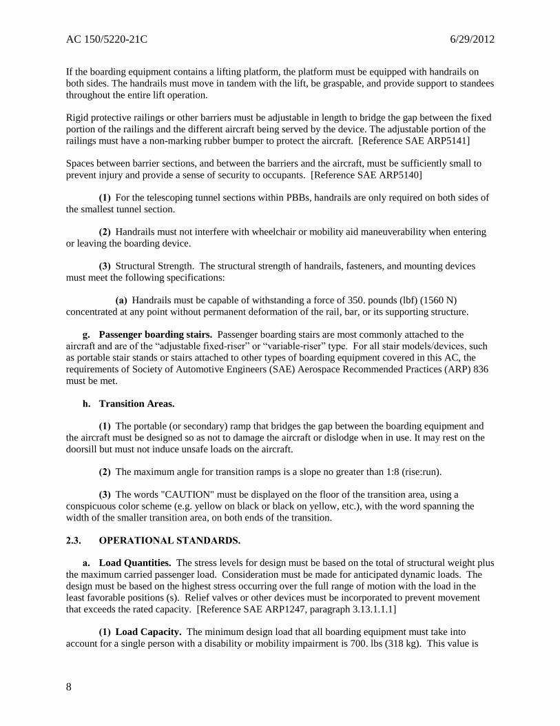
(1) Vertical. Vertical changes in level are permitted up to 0.25 in (6.40 mm) (Figure 4).
Changes in level greater than 0.25 in (6.40 mm) must conform to the specifications for slopes found in
this section. [Reference 36 CFR Part 1191, Appendix D, Section 303]
0.25 in [6.50 mm] MAXIMUM
Figure 4. Vertical Change in Level (cross section)
(2) Horizontal. The maximum horizontal gap allowable along the path to the aircraft can be no
greater than 1.25 in (32 mm). [Reference 36 CFR Part 1191, Appendix D, Section 410.4]
(3) Slopes.
(a) For elevation changes between 0.25 in (6.40 mm) and 0.50 in (13 mm), the path must
be beveled with a slope not steeper than 1:2. Note that for changes in level up to 0.50 in (13 mm), either a
combination of vertical and sloped changes can be provided (Figure 5a), or the entire change may be
sloped (Figure 5b).

AC 150/5220-21C 6/29/2012
6
1/4 in [6.40 mm] 2
1
2
1
1/4 in [6.40 mm]
1/4 in TO 1/2 in
[6.40 mm TO 12.80 mm]
a. COMBINATION CHANGE IN ELEVATION UP TO 0.50 in [13 mm]
b. SLOPED CHANGE IN ELEVATION UP TO 0.50 in [13 mm]
Figure 5. Slope Changes
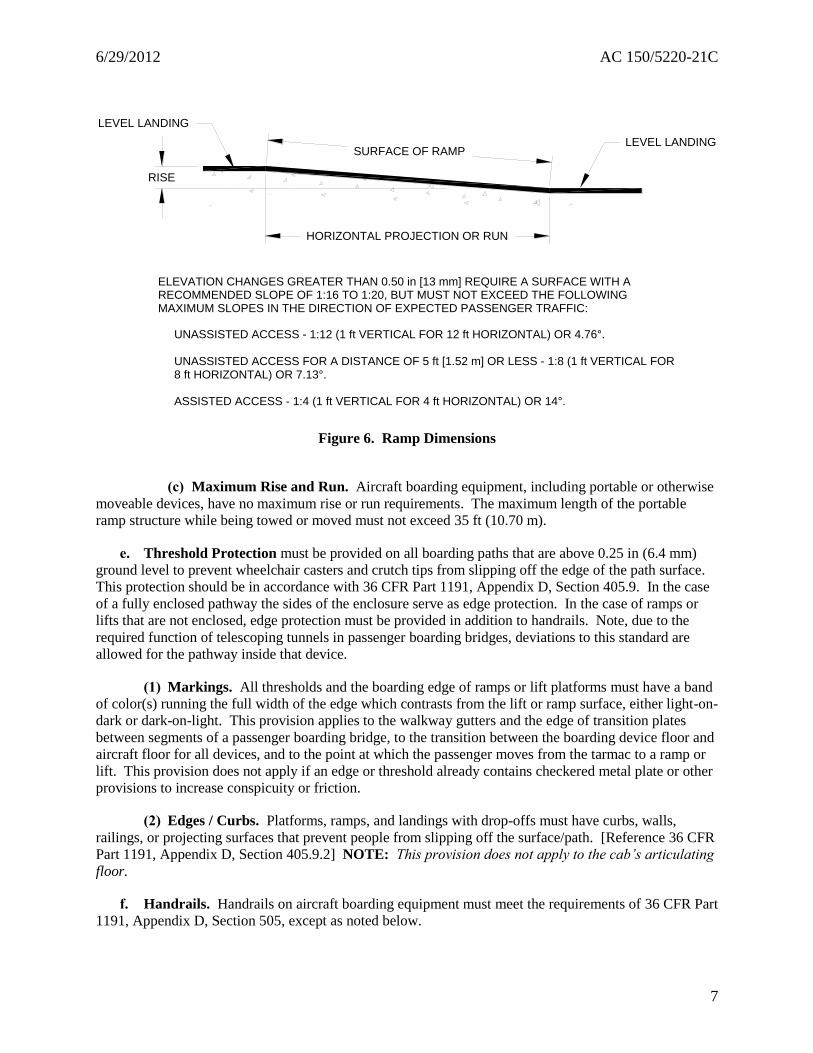
(b) Elevation changes greater than 0.50 in (13 mm) require a surface with a recommended
slope of 1:16 to 1:20, but must not exceed the following maximum slopes (Figure 6) in the direction of
expected passenger traffic. NOTE: The level landing requirement does not apply to the top of ramps
(which may have a smaller transition ramp or floating bridge in place) or to PBBs.
6/29/2012 AC 150/5220-21C
7
SURFACE OF RAMP
HORIZONTAL PROJECTION OR RUN
LEVEL LANDING
LEVEL LANDING
ELEVATION CHANGES GREATER THAN 0.50 in [13 mm] REQUIRE A SURFACE WITH ARECOMMENDED SLOPE OF 1:16 TO 1:20, BUT MUST NOT EXCEED THE FOLLOWINGMAXIMUM SLOPES IN THE DIRECTION OF EXPECTED PASSENGER TRAFFIC:
UNASSISTED ACCESS - 1:12 (1 ft VERTICAL FOR 12 ft HORIZONTAL) OR 4.76°.
UNASSISTED ACCESS FOR A DISTANCE OF 5 ft [1.52 m] OR LESS - 1:8 (1 ft VERTICAL FOR8 ft HORIZONTAL) OR 7.13°.
ASSISTED ACCESS - 1:4 (1 ft VERTICAL FOR 4 ft HORIZONTAL) OR 14°.
RISE
Figure 6. Ramp Dimensions
(c) Maximum Rise and Run. Aircraft boarding equipment, including portable or otherwise
moveable devices, have no maximum rise or run requirements. The maximum length of the portable
ramp structure while being towed or moved must not exceed 35 ft (10.70 m).
e. Threshold Protection must be provided on all boarding paths that are above 0.25 in (6.4 mm)
ground level to prevent wheelchair casters and crutch tips from slipping off the edge of the path surface.
This protection should be in accordance with 36 CFR Part 1191, Appendix D, Section 405.9. In the case
of a fully enclosed pathway the sides of the enclosure serve as edge protection. In the case of ramps or
lifts that are not enclosed, edge protection must be provided in addition to handrails. Note, due to the
required function of telescoping tunnels in passenger boarding bridges, deviations to this standard are
allowed for the pathway inside that device.
(1) Markings. All thresholds and the boarding edge of ramps or lift platforms must have a band
of color(s) running the full width of the edge which contrasts from the lift or ramp surface, either light-on-
dark or dark-on-light. This provision applies to the walkway gutters and the edge of transition plates
between segments of a passenger boarding bridge, to the transition between the boarding device floor and
aircraft floor for all devices, and to the point at which the passenger moves from the tarmac to a ramp or
lift. This provision does not apply if an edge or threshold already contains checkered metal plate or other
provisions to increase conspicuity or friction.
(2) Edges / Curbs. Platforms, ramps, and landings with drop-offs must have curbs, walls,
railings, or projecting surfaces that prevent people from slipping off the surface/path. [Reference 36 CFR
Part 1191, Appendix D, Section 405.9.2] NOTE: This provision does not apply to the cab’s articulating
floor.
f. Handrails. Handrails on aircraft boarding equipment must meet the requirements of 36 CFR Part
1191, Appendix D, Section 505, except as noted below.
AC 150/5220-21C 6/29/2012
8
If the boarding equipment contains a lifting platform, the platform must be equipped with handrails on
both sides. The handrails must move in tandem with the lift, be graspable, and provide support to standees
throughout the entire lift operation.
Rigid protective railings or other barriers must be adjustable in length to bridge the gap between the fixed
portion of the railings and the different aircraft being served by the device. The adjustable portion of the
railings must have a non-marking rubber bumper to protect the aircraft. [Reference SAE ARP5141]
Spaces between barrier sections, and between the barriers and the aircraft, must be sufficiently small to
prevent injury and provide a sense of security to occupants. [Reference SAE ARP5140]
(1) For the telescoping tunnel sections within PBBs, handrails are only required on both sides of
the smallest tunnel section.
(2) Handrails must not interfere with wheelchair or mobility aid maneuverability when entering
or leaving the boarding device.
(3) Structural Strength. The structural strength of handrails, fasteners, and mounting devices
must meet the following specifications:
(a) Handrails must be capable of withstanding a force of 350. pounds (lbf) (1560 N)
concentrated at any point without permanent deformation of the rail, bar, or its supporting structure.
g. Passenger boarding stairs. Passenger boarding stairs are most commonly attached to the
aircraft and are of the “adjustable fixed-riser” or “variable-riser” type. For all stair models/devices, such
as portable stair stands or stairs attached to other types of boarding equipment covered in this AC, the
requirements of Society of Automotive Engineers (SAE) Aerospace Recommended Practices (ARP) 836
must be met.
h. Transition Areas.
(1) The portable (or secondary) ramp that bridges the gap between the boarding equipment and
the aircraft must be designed so as not to damage the aircraft or dislodge when in use. It may rest on the
doorsill but must not induce unsafe loads on the aircraft.
(2) The maximum angle for transition ramps is a slope no greater than 1:8 (rise:run).
(3) The words "CAUTION" must be displayed on the floor of the transition area, using a
conspicuous color scheme (e.g. yellow on black or black on yellow, etc.), with the word spanning the
width of the smaller transition area, on both ends of the transition.
2.3. OPERATIONAL STANDARDS.
a. Load Quantities. The stress levels for design must be based on the total of structural weight plus
the maximum carried passenger load. Consideration must be made for anticipated dynamic loads. The
design must be based on the highest stress occurring over the full range of motion with the load in the
least favorable positions (s). Relief valves or other devices must be incorporated to prevent movement
that exceeds the rated capacity. [Reference SAE ARP1247, paragraph 3.13.1.1.1]
(1) Load Capacity. The minimum design load that all boarding equipment must take into
account for a single person with a disability or mobility impairment is 700. lbs (318 kg). This value is
6/29/2012 AC 150/5220-21C
9
derived from an unoccupied personal mobility aid weighing up to 350 lbs (160 kg) and a passenger
weighing up to 350 lbs (160 kg). The actual design load must be appropriate for the service. If it is a lift
designed to be occupied only by the passenger in a personal mobility aid then the design load might be
700. lbs (318 kg); if two boarding agents are to accompany the passenger, everyone’s combined weight
should be included in the design load.
(2) Load Bearing Surfaces. The entire surface along the passenger pathway and platform
surfaces must be capable of supporting the minimum design load (average live load of 40.0 psf or 195
kg/m2), including the edges of equipment that are adjacent to the aircraft door. The purchaser will
specify the maximum number of personnel that a particular boarding device must safely support.
(3) Maximum Loads and Stresses. The maximum loads and stresses of boarding equipment
must meet the design requirements recommended by the American Institute of Steel Construction (AISC)
“Steel Construction Manual.” The maximum loads and stresses for all other types of aircraft boarding
equipment must meet the requirements of SAE ARP1247, paragraph 3.13.1.1, “Mechanical Design.”
(4) Environmental Loads.
(a) Wind Load. The boarding equipment structure must withstand wind loads of:
Up to 90. mph (160 km/h), for 3 second gusts, while in use and occupied; and
Up to 70. mph (110 km/h), for sustained winds.
(b) Temperature Load. Unless otherwise specified, the boarding equipment structure must
be designed for a uniform temperature increase or decrease of 70 degrees F (21 degrees C).
(c) Seismic (Earthquake) Load. All boarding equipment structures and components must
be designed in accordance with local requirements.
b. Lighting must be provided at all points along the boarding path, including the landing sill,
platform, and operator compartment, at a recommended level of 20 foot-candles (215 lux), or a minimum
of 15 foot-candles (161 lux) or greater, as measured from the floor-level. [Source: FAA HF-STD-001,
paragraph 13.4] The lighting for emergency lighting requirements is a minimum of 5 foot-candles (54
lux), as measured from the floor-level. This allows for all passengers the ability to safely negotiate a path
with numerous transitions that occur within a short distance. Where sufficient lighting is available from
the terminal, additional lighting for ramps is not required.
c. Operating Times.
(1) Setup/Deployment Time. The time required for a trained and proficient operator to set up
and deploy the device upon arrival at the passenger loading area or aircraft must be 1 minute or less.
(2) Enplaning / Deplaning Time. The time required to convey a passenger onto the device and
to the doorsill level must be 2 minutes or less. The time to deplane a passenger must also be 2 minutes or
less.
(3) Storage Preparation Time. The time required to prepare the device for standby storage
must be 3 minutes or less.
AC 150/5220-21C 6/29/2012
10
d. Total Life. The device must be designed to perform its intended function for its “total life”
period, when maintained according to the manufacturer’s instructions. The “total life” for which the
equipment is designed, assuming it is used and maintained in accordance with the manufacturer’s
recommendations, must be a minimum of:
(1) 20 years, based on a frequency of use of 5000 cycles per year (for PBBs);
(2) 10 years, based on a frequency of use of 1000 cycles per year (for ramps and lifts); or
(3) 20 years, based on a frequency of use of 1000 cycles per year (for boarding chairs).
e. Environmental.
(1) If specified by the purchaser, boarding equipment must be capable of operating on a level
surface in 2 in (5 cm) of snow.
(a) Ramps and lifts must meet the environmental requirements of SAE ARP 1247, paragraph
3.6. The purchaser may specify more extreme temperature ranges if required.
(b) Environmental requirements for PBBs are as follows:
(i) Weather. The PBB and all associated outdoor mounted equipment must be designed
to withstand the following extreme climatic conditions and operate without damage or
failure:
Ambient temperature range: -25 degrees F (-32 degrees C) to +123 degrees F
(+52 degrees C) ambient outdoor air temperature. The purchaser may specify
more extreme limits if required.
Relative Humidity: 5% to 90%.
General Environment: Dust and airborne hydrocarbons resulting from jet fuel
fumes.
(ii) Components must be protected from mechanical, electrical, and corrosion damage
causing impairment of operation due to rain, snow, ice, sand, grit, and deicing fluids.
(iii) All electric motors, controls, and electrical wiring / equipment placed outdoors must
be weatherproof in order to protect the equipment and connections from the elements.
(iv) All non-moving structural components and materials must be individually and
collectively designed and selected to serve the total life requirement under such
conditions. Moving or working components, such as tires, aircraft closures, motors,
brakes, etc. are exempt from this provision.
(v) Internal Conditions. If specified by the purchaser, the terminal end of the PBB
must be designed to resist excessive temperature (100 degrees F or 38 degrees C) and
exhaust fumes, such as those produced by aircraft engines and ground service equipment.
6/29/2012 AC 150/5220-21C
11
f. Aircraft Compatibility.
(1) Aircraft Types. The purchaser will specify the aircraft required to be served by the boarding
equipment.”
(2) Design Considerations.
(a) All aircraft models specified by the purchaser to be served must be surveyed by the
manufacturer for compatibility. The following aircraft size/configuration factors will have a significant
effect on the design of the device:
(i) Aircraft doorsill height.
(ii) Aircraft door width.
(iii) Aircraft door location.
(iv) Aircraft components adjacent to the door constituting obstructions (wing, tail,
engine nacelle, propeller, etc.)
(v) Airstairs / airdoor.
(vi) Airstair handrails.
(vii) Vertical movements of the aircraft (doorsill) during emplaning / deplaning.
(b) If an aircraft to be served has a stairway that cannot be retracted while the door is open,
the device must be designed to operate with the stairway deployed. (Note: This requirement is not
applicable to PBBs)
(3) Aircraft Closure (for PBBs). The aircraft end of the cab must be equipped with a folding
bellows aircraft closure. The closure, when fitted to the aircraft fuselage, must surround both the open
aircraft door and the doorway to protect passengers from the elements. The covering must repel water, be
highly tear resistant, and remain flexible from -31 degrees F (-35 degrees C.) to +123 degrees F (52
degrees C). The aircraft closure may be any color, as specified by the purchaser.
2.4. INSTALLATION AND ACCEPTANCE STANDARDS.
a. Installation (may not be applicable to ramps or lifts).
(1) Prior to installation, the manufacturer must obtain all site construction, environmental, and
coordination requirements for installation of the PBB at the airport.
(2) Unless otherwise specified by the purchaser, installers of mechanical and electrical work
must participate in any pre-installation meetings at the project site to review conditions of other related
project work.
(3) The manufacturer must provide trained personnel at the time of delivery to place the device
into operation.
b. Transportability. If highway transportability is specified by the purchaser, the device must meet
the requirements of SAE ARP1247, paragraph 3.7.
AC 150/5220-21C 6/29/2012
12
c. Quality Assurance. The manufacturer must test all of the equipment installed under this
specification and demonstrate its proper operation to the purchaser. The manufacturer must furnish all
required labor, testing, instruments and devices required for the conduct of such tests.
(1) The manufacturer must install all electrical, instrumentation, and mechanical works to the
satisfaction of the purchaser, with inspecting authorities having jurisdiction.
(2) The manufacturer must notify the purchaser in writing of any instances in the specifications
that are in conflict with applicable codes. The manufacturer must perform all work in accordance with
applicable laws, rules, or regulations.
(3) Deviations from the specifications required for conformance with the applicable codes and/or
laws must be corrected immediately, but not until such deviations have been brought to the attention of
the purchaser.
(4) For applicable codes and/or laws that govern the minimum design requirements; where this
AC calls for materials, vents, ductwork, sizes, design details, etc., in excess of the code requirements, the
AC takes precedence.
d. Inspection. Inspections must meet the provisions of SAE ARP1247, paragraph 4.3, and if
applicable, the U.S. Access Board Guidelines for Aircraft Boarding Chairs (1987), paragraph 3.3.c.
e. Testing. After the equipment has been installed and the various units have been inspected,
adjusted, and placed in correct operating condition, the equipment must be field tested in accordance with
the purchasers testing procedures and requirements. The field tests must demonstrate that the equipment
functions are in compliance with the specifications over the entire range of operation. The manufacturer
must report any unusual conditions and correct deficiencies of any of the units.
(1) Preliminary Qualification Tests. Preliminary qualification tests may be specified by the
purchaser.
(2) Formal Qualification Tests. Formal qualification tests may be specified by the purchaser.
(3) Specification Conformance Tests. The manufacturer must perform any tests referred to in
SAE ARP1247, paragraph 4.6, if specified by the purchaser. The purchaser may elect to accept
documentation of previously run tests.
(4) Reliability Test and Analysis. A reliability test and analysis may be specified by the
purchaser.
f. Data and Analyses. If requested by the purchaser, the requirements of SAE ARP1247,
paragraph 4.4, must be met by the manufacturer.
g. Manuals and Publications. The following operation and maintenance manuals must accompany
the delivered equipment. The quantity of items is specified by the purchaser. No special format is required
(except for PBBs, where the manuals must follow the intent of the Air Transport Association (ATA)
Specification 101).
(1) Operator’s handbook.
(2) Illustrated parts breakdown and list.
6/29/2012 AC 150/5220-21C
13
(3) Preventive maintenance schedule.
2.5. POST-DELIVERY STANDARDS.
a. Training. The manufacturer must provide trained personnel at the time of delivery to adequately
train airport/airline staff in the operation and maintenance of the boarding equipment.
(1) For both operators and technicians, training must include written operating instructions that
depict the step by step operational use of the device, plus instruction in the proper use of a boarding chair,
whether or not such a chair is provided with the boarding equipment. Written instructions must include,
or be supplemented by, materials which can be used to train subsequent new operators.
(2) For technicians, training topics must include trouble shooting and problem solving, in the
form of theory and hands-on training.
(3) A minimum of 2 hours of training for designated operators, focusing on controls and
emergency procedures and including a check-ride, must be provided by the manufacturer. A minimum of
8 hours of training for technicians / maintenance staff must be provided by the manufacturer. Training
selected personnel as part of a “Train the Trainer” program will also satisfy this requirement.
(4) Training time per day must not exceed 8-hour shifts, unless otherwise specified by the
purchaser.
(5) Upon the completion of training, the manufacturer must issue each participant a certificate of
competency.
b. Maintenance / Reliability. The equipment and its accessories must be designed and constructed
with reliability of operation as a primary consideration. The minimum reliability design requirement is
that the equipment be designed to operate between periodic preventive maintenance activities of 6 months
(for PBBs) or 4 months/100 lift cycles (whichever occurs first, for all other boarding equipment). The
above interval does not apply in cases where the component manufacturer recommends more frequent
maintenance intervals.
(1) Preventive. The manufacturer must develop and provide to the purchaser written
documentation on recommended preventive maintenance actions.
(a) For the purpose of this specification, normal servicing of fuel, oil, tire pressure, battery,
and water are not considered preventive maintenance.
(b) Boarding chairs must meet the provisions of the U.S. Access Board Guidelines for
Aircraft Boarding Chairs (1987), paragraph 3.3.a.
(2) Cleaning. The manufacturer must develop and provide to the purchaser written
documentation on recommended cleaning procedures, including solvent types and tools.
(a) Boarding chairs must meet the provisions of the U.S. Access Board Guidelines for
Aircraft Boarding Chairs (1987), paragraph 3.3.b.
(3) Inspection. The manufacturer must develop and provide to the purchaser written
documentation on regularly scheduled maintenance inspection procedures. A focus on sensitive
equipment and schedule timelines must be included in the documentation.
AC 150/5220-21C 6/29/2012
14
(4) Spare / Replacement of Parts. The manufacturer must develop and provide to the purchaser a
parts list, including associated replacement/repair costs.
(5) Tools and Test Equipment. The device must meet the requirements of SAE ARP1247,
paragraph 3.12.4.
(a) Boarding chairs must meet the provisions of the U.S. Access Board Guidelines for
Aircraft Boarding Chairs (1987), paragraph 3.3.f.
2.6 PURCHASING SPECIFICATION CLARIFICATIONS.
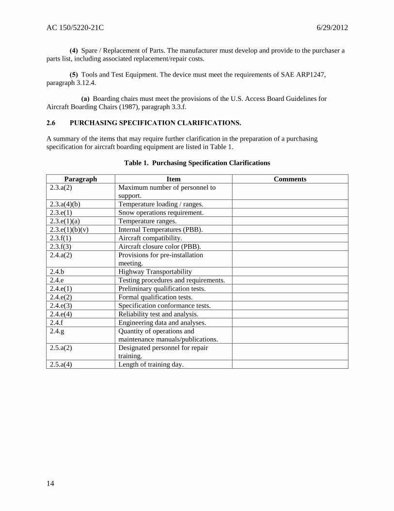
A summary of the items that may require further clarification in the preparation of a purchasing
specification for aircraft boarding equipment are listed in Table 1.
Table 1. Purchasing Specification Clarifications
Paragraph Item Comments
2.3.a(2) Maximum number of personnel to
support.
2.3.a(4)(b) Temperature loading / ranges.
2.3.e(1) Snow operations requirement.
2.3.e(1)(a) Temperature ranges.
2.3.e(1)(b)(v) Internal Temperatures (PBB).
2.3.f(1) Aircraft compatibility.
2.3.f(3) Aircraft closure color (PBB).
2.4.a(2) Provisions for pre-installation
meeting.
2.4.b Highway Transportability
2.4.e Testing procedures and requirements.
2.4.e(1) Preliminary qualification tests.
2.4.e(2) Formal qualification tests.
2.4.e(3) Specification conformance tests.
2.4.e(4) Reliability test and analysis.
2.4.f Engineering data and analyses.
2.4.g Quantity of operations and
maintenance manuals/publications.
2.5.a(2) Designated personnel for repair
training.
2.5.a(4) Length of training day.
6/29/2012 AC 150/5220-21C
15
CHAPTER 3. PASSENGER BOARDING BRIDGES (PBBs)
3.1. GENERAL.
a. Both stationary and moveable PBBs are described in this chapter. They contain rotunda
assemblies, support columns, and corridors.
b. The specifications outlined in this chapter represent the compilation of various source materials
and industry standards, as noted.
3.2. SYSTEM DESCRIPTION.
a. Types. The two main types of PBBs are stationary and moveable. Stationary PBBs are
permanently fixed structures while moveable PBBs have both horizontal and vertical movement about
one end of the system. Except as specifically noted in this AC, the term PBB will refer to moveable type
systems.
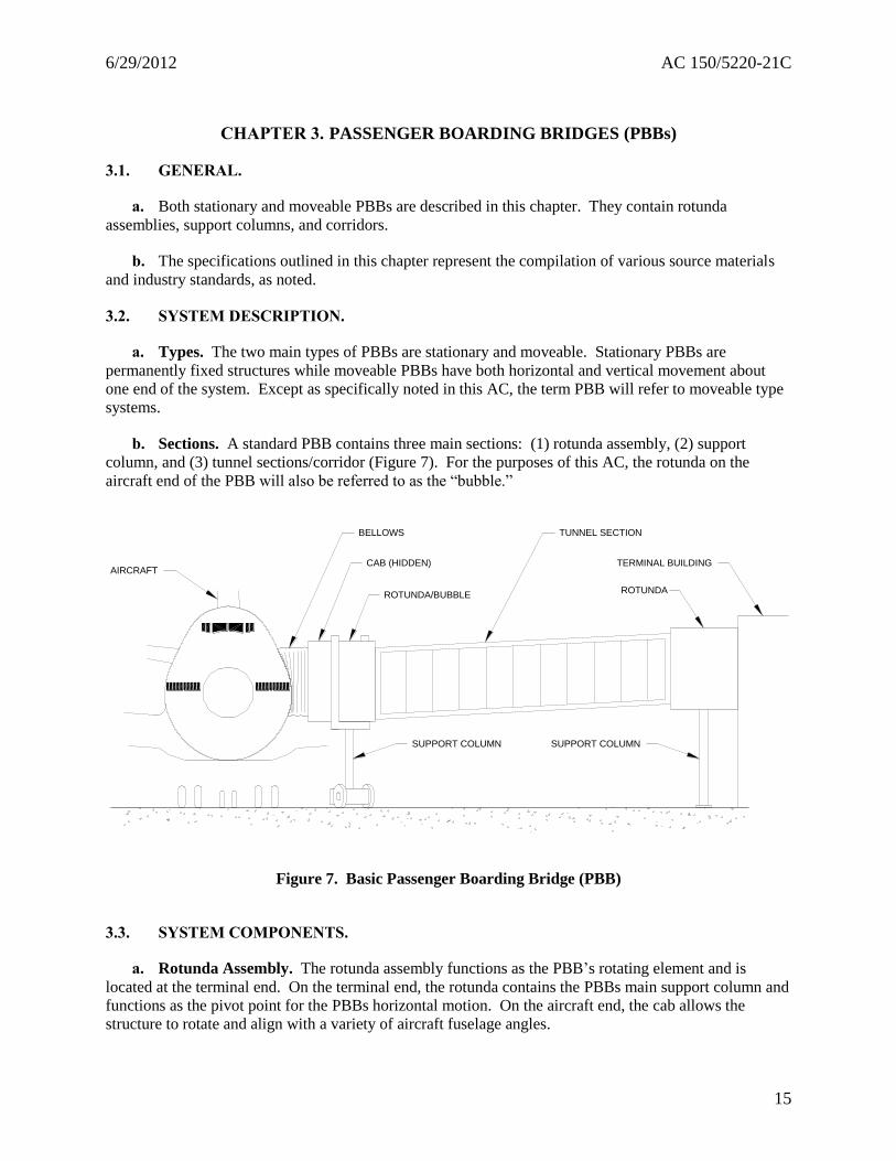
b. Sections. A standard PBB contains three main sections: (1) rotunda assembly, (2) support
column, and (3) tunnel sections/corridor (Figure 7). For the purposes of this AC, the rotunda on the
aircraft end of the PBB will also be referred to as the “bubble.”
ROTUNDA/BUBBLE
SUPPORT COLUMN
TUNNEL SECTION
ROTUNDA
TERMINAL BUILDING
BELLOWS
SUPPORT COLUMN
AIRCRAFTCAB (HIDDEN)
Figure 7. Basic Passenger Boarding Bridge (PBB)
3.3. SYSTEM COMPONENTS.
a. Rotunda Assembly. The rotunda assembly functions as the PBB’s rotating element and is
located at the terminal end. On the terminal end, the rotunda contains the PBBs main support column and
functions as the pivot point for the PBBs horizontal motion. On the aircraft end, the cab allows the
structure to rotate and align with a variety of aircraft fuselage angles.
AC 150/5220-21C 6/29/2012
16
(1) Cab. The cab is the interface of the PBB to the aircraft. It contains the operator
compartment and rotates around the bubble section of the PBB. A service access in the bubble allows the
transfer of maintenance personnel, equipment, and luggage from the PBB to the airport ramp.
(a) Operator Compartment. The operator compartment is positioned on the left side of the
cab (as referenced from inside the cab looking out onto the airport ramp). The primary purpose of the
operator compartment is to house the PBB control station, which contains the control console, service
utilities, and control interlocks required for proper operation. The operator compartment provides a
location for optimum PBB maneuvering visibility without obstructing passenger traffic flow.
b. Tunnel Section / Corridor. The corridor functions as the main element in assisting passenger
movement. Corridors are typically in the form of multiple telescoping tunnel sections (either two or
three) in a wide variety of lengths. The telescoping tunnels are rectangular in cross section, with the
largest cross section located closest to the aircraft.
c. Support Column. The support column is a vertical element that provides the structural support
for the PBB. The main support column is located under the rotunda, while a secondary support column or
vertical lift system is located at the aircraft end of the PBB and is supported by the wheel section or in
some cases an additional foundation. The support column is custom built to meet specific site conditions,
including the required height for the terminal floor and varying qualities and types of foundations in the
airport ramp.
3.4. PERFORMANCE.
a. Functions. The equipment must perform the following functions:
(1) Provide a means for boarding passengers directly from the terminal boarding area to the
aircraft door.
(2) Allow the aircraft end of the PBB to move vertically or horizontally in order to position the
floor of the PBB to be equal to the lower lip of the aircraft doorsill, providing a level boarding surface.
(3) Provide a space in the cab for temporary placement of oversized carry-on luggage and other
equipment to function as a staging area during aircraft loading/unloading operations.
(4) Provide passenger protection from external weather elements.
(5) Provide passenger protection from ramp fuel spill fires (NFPA 415).
b. Operational Standards.
(1) Movement. Unless mentioned below, there are no maximum velocity or acceleration limits
for the PBB when occupied by the control station operator. When the PBB is mated to the aircraft door
for passenger loading/unloading operations, the maximum amount of acceptable movement is that which
allows the automatic leveling system to function properly, as described below.
(a) Maneuvering Operations.
(i) The cab rotation angle can vary depending on customer requirements.
(ii) The cab rotation speed can be fixed or variable between 0 and 4 degrees per second.

6/29/2012 AC 150/5220-21C
17
(b) Docking Operations. The PBB should be equipped with sensors to safely prevent
dangerous contact with the aircraft. The type of sensor or spacer limit switch will be specified by the
purchaser, if desired.
(2) Stability / Automatic Leveling.
(a) The PBB must be equipped with an automatic leveling system (auto-leveler) for occupant
safety while the unit is mated to the aircraft door. This system allows the PBB to follow changes in the
aircraft elevation that occur during aircraft loading and unloading, and places the cab floor in a level
surface adjacent to the aircraft doorsill height. The auto-leveling system must function with equal
reliability for all aircraft contours.
(b) The auto-leveler must be designed to level automatically while still being capable of
independent, manual adjustment.
(c) To engage the automatic mode, an actuation switch or master key switch must be
positioned to “AUTO”. A manual override switch for manual adjustment must also be available, but
protected to prevent unauthorized adjustments. All auto-leveler switches and controls, either mechanical
or electronic, must be located so that they are in full view of an operator stationed at the control console.
(d) The auto-leveler circuit must include a sustained travel timer. The timer limits auto-level
operation to a time which must be adjustable from 1.6 to 16 seconds (4.0 seconds being recommended).
If the operation exceeds the set time limit it must trigger a fault condition, upon which the system
disconnects all motor power and energizes audible and visual alarms.
(3) Noise and Vibration. All mechanisms for actuating, guiding, and restraining the PBB and
its associated components must be designed so that no noise or sway, other than that caused from the
auto-leveling equipment (if installed), is apparent to the passengers using the PBB. No operating
vibration or loads must be transmitted to the terminal building or fixed passageway from the PBB.
(4) Operability. The PBB must be capable of operating with any possible combination of
passenger loading, at full load within the temperature ranges specified in this chapter.
(5) Communication Interface. The purchaser will specify the type of communications system
needed for integration into the airport’s system.
(6) Equipment Combinations. In the event that a PBB must maneuver in a way that causes the
slope of the walkway to be greater than 1:4 (rise:run), a ramp can be mated to the PBB platform in order
to keep the slope within an optimum range that is accessible to all passengers.
(7) Bridge Adaptors. Whenever the PBB is used in conjunction with items not suited for
normal operations (e.g. mated to ramps or aircraft with narrow passenger doors), the use of a bridge
adaptor is recommended to increase safety and accessibility. The minimum requirements listed in
Chapter 2 of this AC must be met for all adaptor design, including the following standards:
(a) The exceptions listed in Chapter 2, for standards within a PBB, do not apply to the bridge
adaptor;
(b) The width of the adaptor must be as wide as possible to allow for maximum passenger
movement , but not so wide that it interferes or causes damage to the equipment being adapted; and
AC 150/5220-21C 6/29/2012
18
(c) To help guide passengers along the intended path of travel, any open spaces along the
sides (vertical plane) of the path that are greater than 6 in (15 cm) in the vertical or horizontal direction
must be covered with a thin, durable material. In the case of handrails, material is typically draped or
hung from the top of the handrail down to the floor. The material must be marked in an alternating color
scheme of the operator's choice.
(8) Emergency Operations. The system must incorporate tow lugs to allow the PBB to be
moved in case of an emergency.
(a) The cab station must be furnished with a fire alarm pull station tied to the terminal’s
alarm system, if specified by the purchaser.
(b) The cab area must be equipped with a fire extinguisher and smoke detectors, if specified
by the purchaser.
(c) Power or Equipment Failure. The system must be protected against uncontrolled
movement in the event of a power source failure of any type (i.e., electrical, hydraulic, or pneumatic).
(i) Hydraulic lift cylinders must have pilot-operated checks or counterbalance valves
connected directly to their base fittings to prevent accidental lowering in the event of failure of any line in
the system.
(ii) Electrical or pneumatic lift components must be equipped with brakes to lock the
system in the event of power failure or malfunction.
(iii) The location of emergency controls must be easily identified and must be located so
as not to create a potential hazard to the operator or equipment during operation.
(9) Storage / Security. Unless otherwise specified in this AC or by the purchaser, requirements
needed to properly store and secure the device must be supplied by the manufacturer. Weather doors
must be provided adjacent to the console to seal and secure the interior when the PBB is not in use. These
doors must be swinging double doors that open inward and can be latched open or closed. The clear
width of the weather doors when open must be no less than 36 in (0.91 m). The use of an electric
operated rollup door in lieu of the double swinging doors is an acceptable alternative.
(10) Siting. The PBB must not interfere with the safe operation of mobile aircraft fueling
vehicles or in-ground hydrant fuel delivery systems.
3.5. DESIGN / DEVELOPMENT PHASE.
a. The manufacturer must field verify the dimensions required for fabrication and installation of the
PBB system in the airport environment. This effort includes the responsibility for obtaining actual height
measurements and anchor bolt patterns at each interface with civil/architectural construction by others.
(1) Minimum Interior Clear Dimensions.
Corridor height – 80 in (200 cm).
Corridor width – 50. in (130 cm), or as limited by the rotation of the PBB.
Floor width – 58. in (150 cm).
6/29/2012 AC 150/5220-21C
19
Telescoping tunnel transition ramp width – 56 in (140 cm).
(2) Aircraft Interface.
(a) A double hinge floor must be included in the system to provide a smooth transition
between the level floor of the terminal and the PBB. There must be no raised surfaces along the corridor,
aside from the transition ramps between telescoping tunnel sections, which may introduce a tripping
hazard to the passenger.
(b) Handrails should be provided on both sides of the external portion of hinged transition
ramps. Handrails on transition ramps should extend 12 in (31 cm) beyond the top and bottom of the
transition ramps to provide a stable gripping surface before one is on the ramp. [Reference 36 CFR Part
1191, Appendix D, Section 505.10.1] The transition between telescoping sections is a particular hazard
to persons with mobility impairments and must be made as easy to negotiate as possible. The slopes
listed in 2.2.d.3 of this AC provide a basis for transition ramp design.
(c) Flap-type flexible weather seals must be installed between the transition areas of the
rotunda (between the rotunda and terminal building or fixed passageway) and along the hinged
telescoping tunnel sections.
(d) An extended rotunda corridor must be provided, as required, based on the purchaser’s
specific airport drawings. A haunch or fixed walkway must be provided to ensure structural integrity, as
required by this length.
(3) Service and Access. A service door, landing and stair leading to the apron area constitute the
service access. The service access can be located on the right or left side of the cab end of the PBB. It
provides access between the PBB and apron for authorized personnel. At gate locations with multiple
PBBs, at least one PBB must have service access. For PBBs servicing very tall aircraft, stairs are not
required if the structural integrity of the system is jeopardized, or if they interfere with ramp operations,
as determined by the purchaser.
(a) Service Door.
(i) The service door must open to a landing such that a wheelchair (having the minimum
area requirements listed in paragraph 2.2.b of this AC) can be moved to or from the PBB through this
door. After a passenger who uses a wheelchair has been transferred to their aircraft seat, their wheelchair
may need to be moved to the baggage hold of the aircraft. This procedure is expedited if the chair can be
moved directly from the loading bridge to the airport ramp either using a built in baggage elevator or
through the service door to an exterior lift. Baggage elevators or lifts make it easier to move heavy power
wheelchairs and scooters from the area of the bubble to the airport ramp surface.
(ii) The minimum dimensions of the PBB service door is a width of 32 in (0.81 m) and a
height of 80 in (2 m). The service door must be made of steel, half wire-glass, be of a hollow core design,
unless otherwise prohibited by security regulations or the purchaser, and must meet or exceed the 3/4
hour fire rating per ASTM E152. In addition, the door must be equipped with heavy duty commercial-
type hardware, an automatic door closure, and must open outward onto the landing. A security
device/system for the door, the type as specified by the purchaser, must be provided. A 32 in (0.81 m)
stainless steel kick plate must be installed to cover the lower side portion of the door. A window with a
minimum surface area of 658 sq. in (0.425 sq. m) must be provided in the service door.
AC 150/5220-21C 6/29/2012
20
(b) Service Stairs. The service stairs must conform to the requirements of SAE ARP836,
unless as specified below.
(i) The stair landing must be parallel to the adjacent tunnel floor. It must be covered
with a non-slip tread, and protected on the open sides by galvanized steel handrails, which are designed to
meet the OSHA standards. At the purchaser’s request, a photocell operated light with a protective cage
may be installed by the manufacturer above the landing.
(c) Maintenance Ladder. The manufacturer will provide a maintenance ladder for access to
the roof of the PBB. The ladder must be galvanized or painted with a safety cage at its top. This ladder
will also function as the emergency ladder described above.
(4) Ground Service Connections. The arrangement of standardized locations for ground
service connections on PBBs must conform to SAE ARP4084, or as otherwise specified by the purchaser.
(5) Operator Visibility. The cab must be equipped with a forward facing control console that
allows the system operator to have a full view of the aircraft door during maneuvering and docking
operations.
(a) Operation of the PBB must be able to be accomplished without opening the weather
doors.
(b) The control console must be located behind laminated glass windows. For additional
visibility, windows located in front, left, and right of the operator must be installed. The minimum size of
the windows must be:
Front – surface area of 750 sq. in (0.48 sq. m).
Left – surface area of 300 sq. in (0.2 sq. m).
Right – surface area of 150 sq. in (0.10 sq. m).
(c) If requested by the purchaser, double-row panels should be installed in the cab side-
coiling curtains, the size of which is dependent on the width of the rotunda panels.
(d) Either a cab mirror or cameras (as chosen by the purchaser) must be mounted to allow the
operators to view the apron area from their console.
b. SAFETY. It is the responsibility of the manufacturer to ensure that the equipment contains all
safety features required to protect the equipment, the operator(s), the passenger load, and the aircraft
serviced, in accordance with all generally accepted good design practices. All design features intended to
protect the equipment operator(s) must provide similar protection to the passenger(s).
(1) Personnel Safety.
(a) Edge tracks/walkway gutters (from the telescopic function) must be designed so as to
prevent persons with disabilities or mobility impairments from damaging their equipment if their
equipment enters the edge track groove. Manufacturers must comply with the marking requirements
listed in 2.2.e.(1).
6/29/2012 AC 150/5220-21C
21
(b) All pinch and shear points, sharp edges and protruding objects must be eliminated
wherever possible and practical. If elimination is not possible, adequate guarding must be achieved to
prevent injury and/or damage exposure. [Reference SAE ARP1247, paragraph 3.9.12.]
(c) Push/pull forces required to move features other than control handles and access doors
must be limited to 60 lb (27.2 kg), when the operator is standing upright. [Reference SAE ARP1247,
paragraph 3.9.13.]
(d) Stairs, ladders, scaffolds, platforms, etc. must comply with the applicable OSHA
requirements. [Reference SAE ARP1247, paragraph 3.9.14.]
(e) Where practical and possible, access to work areas must be provided by means of stairs
rather than ladders. [Reference SAE ARP1247, paragraph 3.9.16.]
(f) Stair risers, treads, and stair and ladder angles must conform to OSHA promulgated
standards and documents for Industrial Operations. Critical angles must be avoided where practical and
possible. [Reference SAE ARP1247, paragraph 3.9.17.]
(g) Steps and ladder rungs must be of open, nonskid material. [Reference SAE ARP1247,
paragraph 3.9.18.]
(h) Non-slip surfaces must be provided in all areas where personnel will be required to walk
or work during normal operations. [Reference SAE ARP1247, paragraph 3.9.19.]
(i) The corridor must be insulated to meet industry standards.
(j) Material used in the fabrication of the sub floor must meet the requirements of NFPA
415.
(k) If requested by the purchaser, heat sensors must be located beneath the bridge.
(2) Equipment Safety.
(a) If required, the type, location, and color of reflecting devices will be specified by AC
150/5210-5 Painting, Marking, and Lighting of Vehicles Used on an Airport.
(b) Consideration must be given for protection of lamps and reflectors against damage if
dictated by normal design practice; i.e., likelihood of damage. [Reference SAE ARP1247, paragraph
3.10.2]
(c) All components and systems must be fail-safe wherever practical. [Reference SAE
ARP1247, paragraph 3.10.4]
(d) All lifting, mobility, and/or positioning controls must be of the “deadman” type.
[Reference SAE ARP1247, paragraph 3.10.6]
(e) Relief valves must be provided in all hydraulic and pneumatic systems to prevent
sustained pressures in excess of rated working pressure. [Reference SAE ARP1247, paragraph 3.10.7]
(f) If requested by the purchaser, a 5 pound (2.27 kg) BC-rated fire extinguisher should be
mounted in the PBB at a location easily accessible to the operator.
AC 150/5220-21C 6/29/2012
22
(3) Operational Safety. Limit switches must be installed to control the PBB rotation limits.
(a) The over-travel swing limit switch must be located on the support column. The trip plate
for this switch must be located on the rotunda and be adjustable in order to meet local conditions. When
this switch is actuated, it must cut off all control power so that the PBB can only be moved by using the
by-pass switch in the control console. The PBB should be equipped with mechanical stops to prevent
collapse of the telescoping tunnel sections.
(b) Equipment must be provided at the rotunda to sense and limit the normal rotational
position of the PBB swing. The actuation of this warning buzzer must be adjustable to meet local
conditions. The warning buzzer must be within the over-travel limit envelope and signal the rotational
operational limits.
c. Mechanical / Structural Loading.
(1) Structural members manufactured of non-ductile materials must be designed to meet the
requirements of the American Institute of Steel Construction (AISC) Steel Construction Manual.
(2) The PBB system must be designed with sufficient structural rigidity so that deflections due to
load, wind, and motions of working parts do not create interferences, cause malfunctioning of the
equipment, or present safety hazards to personnel, aircraft, or the system itself. [Reference SAE
ARP1247, paragraph 3.13.1.1.8] The structural design must provide sufficient torsional rigidity to avoid
excessive sway when the PBB is brought to a gradual stop.
(3) In the case of standard structural or component assemblies used by the end product
manufacturer, certification of the application by the component manufacturer will constitute structural
acceptability of such components. [Reference SAE ARP1247, paragraph 3.13.1.1.9]
(4) Other.
(a) The roof, wall, and floor panels must be constructed from a minimum of 0.079 in (2 mm)
thick flat steel.
(b) Shoulder bolts, bearings, or bushings must be used when attaching parts having relative
rotary or linear motion. [Reference SAE ARP1247, paragraph 3.13.1.1.10]
(c) Caster and wheel types and applications must conform to the standards of the Caster and
Floor Truck Manufacturer’s Association. [Reference SAE ARP1247, paragraph 3.13.1.1.11]
(d) The wheels used must be of a type and size that will not damage or cause undue wear to
the surface over which they will normally operate. [Reference SAE ARP1247, paragraph 3.13.1.1.12]
d. Electrical.
(1) General.
(a) The PBB must have an electrical disconnect panel, mounted on the rotunda support
column. Transformers should be supplied as needed to adapt the specified terminal power to the PBB’s
electrical requirements.
6/29/2012 AC 150/5220-21C
23
(b) Push button operators must by UL listed and rated for the loads which they control.
[Reference SAE ARP1247, paragraph 3.13.1.2.3]
(c) All circuits must have suitable overload protection. Fuses and circuit breakers must be
grouped in convenient locations and suitably marked for size and function. Logical grouping of circuits is
anticipated. [Reference SAE ARP1247, paragraph 3.13.1.2.4]
(d) All wiring must be routed away from heat sources. Wiring must be adequately supported
to protect it from damage, snow and ice buildup, bumping, kinking, and flexing. [Reference SAE
ARP1247, paragraph 3.13.1.2.5]
(e) Common wire splices must not be used. Connections must be made using terminal strips
and staked lugs or by patent connectors. Terminals must meet the applicable requirements of SAE J561,
J858, and J928. [Reference SAE ARP1247, paragraph 3.13.1.2.6]
(f) Wiring must meet the applicable requirements of SAE J878, J1127, and J1128.
[Reference SAE ARP1247, paragraph 3.13.1.2.7]
(g) Each conductor must be sized to have current carrying capacity, equal to or greater than
the capacity of the fuse or circuit breaker provided in its circuit, as allowed by the National Electrical
Code (NEC). Optional and add-on components must be considered in sizing and in the number of
conductors provided. [Reference SAE ARP1247, paragraph 3.13.1.2.8]
(h) Grommets and suitable anti-chafe material must be used where the wires are required to
pass through a relief or opening which exposes the wire to possible chaffing. [Reference SAE ARP1247,
paragraph 3.13.1.2.9]
(i) Each wiring conductor must be identified by color or number in accordance with a wiring
diagram accessibly displayed in the system and/or in an accompanying document. [Reference SAE
ARP1247, paragraph 3.13.1.2.10]
(j) Any concealed wiring running within walls or other inaccessible areas must be contained
in conduit for the length of the run. [Reference SAE ARP1247, paragraph 3.13.1.2.11]
(k) Wiring terminals must be protected by insulating boots or heat-shrinkable tubing.
[Reference SAE ARP1247, paragraph 3.13.1.2.12]
(l) Quick disconnect fittings, where required, must be UL listed receptacles and plugs, or
equivalent. [Reference SAE ARP1247, paragraph 3.13.1.2.13]
(m) All electrical connections, including terminal strips and battery terminals, must be
protected with suitable covers or enclosures to prevent accidental contact and short circuiting. [Reference
SAE ARP1247, paragraph 3.13.1.2.14]
(n) Electrical interlocks must be fail-safe design. [Reference SAE ARP1247, paragraph
3.13.1.2.15]
(o) Electrical devices including lights, switches, relays, wiring, and terminals, when located
in an area exposed to weather, must be of weatherproof design or protected by weatherproof enclosures.
[Reference SAE ARP1247, paragraph 3.13.1.2.16]
AC 150/5220-21C 6/29/2012
24
(p) Spark-producing electrical components must be located at least 18 in (0.457 m) above
ground level wherever possible. [Reference SAE ARP1247, paragraph 3.13.1.2.17]
(q) All electrical junction boxes used on the PBB must be made from high strength non-
corrosive materials NEMA 4 rated or greater. Painted steel boxes will not be considered acceptable.
Electrical disconnects and the rotunda column electrical disconnect boxes are excluded from this
requirement.
(r) Cabs, tunnel sections, service stairs and landings, rotundas, and all electrical items must
be interconnected by a continuous grounding conductor. The main grounding conductor will be provided
with the power supply feeder.
(s) A four pair CAT6 wire outlet for the installation of telephone or intercom equipment
must be installed on left side wall adjacent to the control console.
(t) Duplex outlets (unswitched 120 volt, single phase, 15 amp) must be located adjacent to
the control console, on the lower portion of the drive column (GFI), and in the corridor.
(2) Cable Conveyance System.
(a) The telescoping tunnels must be equipped with an exterior electrical cable conveyance
system. This system must be designed to be accessible to maintenance personnel for inspection or cable
addition at all PBB positions and operating conditions. Access to the conveyance system must not impede
passenger traffic or PBB operation. The system must be capable of supporting a combination of cables
and hoses with a maximum weight of 12 pounds per foot (17.89 kg per m) and a maximum cross-
sectional area of 12 square inch (77 square centimeters) consisting of two 6 square inch (39 square
centimeter) areas. The largest tunnel must be equipped with an aluminum wireway to continue electrical
cable routing beyond the electrical cable conveyance system.
(b) The cable conveyance system must be of heavy-duty construction such that the system is
free from failure or defects for a minimum of five years from final acceptance. Shipping must be
considered when designing and constructing the cable conveyance system to avoid damage to the system
or suspended components during the PBB installation.
(3) Lighting. Lighting must meet the requirements of AC 150/5210-5.
(a) Exterior floodlights must be provided for nighttime operation to illuminate the apron area
ahead of the PBB. A floodlight must also be provided to illuminate the drive column wheel bogey area.
This light must be located under the tunnel section. All flood lights must include a protective cage.
(b) A weatherproof lighting fixture producing a minimum of 5 foot-candles (54 lux) must
also be provided outside the weather doors to illuminate the cab-aircraft interface.
(c) A minimum of 5 foot-candles (54 lux) of illumination must be provided:
On all controls and placards in a glare free manner.
At all operator positions and work areas by means of flood, spot, or dome lights.
[Reference SAE ARP1247, paragraph 3.13.1.2.18]
6/29/2012 AC 150/5220-21C
25
(d) All external lamps must be heavy-duty type. [Reference SAE ARP1247, paragraph
3.13.1.2.20]
(4) Electromagnetic Interference. The equipment must meet FCC Part 15 rules for
electromagnetic interference emissions. It must be capable of operating through the entire amplitude
modulated aircraft radio frequency range of 75 MHz – 136 MHz.
e. Hydraulic and Electro-Mechanical. The device must meet the requirements of SAE ARP1247,
paragraph 3.13.1.3, except as specified below.
(1) Raising and lowering of the PBB must be accomplished by one person and through either two
recirculating ball screws or two or more hydraulic cylinders, powered by an electric or engine driven
pump. The system must incorporate a fail-safe hydraulic and/or mechanical system designed to prevent
lowering in the event of component failure.
(2) Hydraulic fluid must meet manufacturer’s requirements for the hydraulic system components.
(3) The materials used for each hydraulic line must be consistent with its application. Fixed lines
must be made of high quality steel or stainless steel. Flexible lines must be used only where necessary.
(4) The towing provisions of 3.13.1.3 do not apply to PBBs.
(5) If requested by the purchaser, a potable water system for supplying the aircraft with fresh
water will be provided. The potable water system must be equipped with an interlock to prevent the PBB
from retracting from the aircraft while hooked up to the system.
f. Heating, Ventilation, and Air Conditioning System. If requested by the purchaser, the
manufacturer must provide suitable means for ensuring adequate ventilation, heating, or cooling through
the tunnel sections of the PBB, in accordance with FAA HF-STD-001, paragraph 13.2.
g. Steering / Positioning System.
(1) Drive Column. The drive column and control systems must be designed for smooth, quiet
operation. The drive column is divided into two major components: Vertical Drive and Horizontal Drive.
The vertical and horizontal movements must be able to be operated simultaneously.
(a) Vertical Drive. The PBB must be moved vertically by means of two recirculating ball
bearing screw assemblies (for alternative hydraulic design requirements, see paragraph 3.5.e of this AC).
(i) Each assembly must be independent with individual motors and brakes. Each
assembly must be capable of supporting the PBB under a full design load. This design must provide
100% redundancy.
(ii) The ball nut must be equipped with wiper brushes to remove grit or dirt from the
screw threads.
(iii) The ball nut must be equipped with a special thread profile designed to support the
PBB in the absence of the recirculating ball bearings.
AC 150/5220-21C 6/29/2012
26
(iv) The vertical drive motors must be AC induction motors which include an integral
reducer and brake. The brakes must be spring applied and electrically released. The brakes must hold
securely at all elevations whenever electrical power is not applied.
(v) A fault detector must sense differential motion of the ball screw assemblies. The
detector must be able to disconnect electrical power from the vertical drive motors if a fault is detected.
(vi) The manufacturer must provide a disconnect switch for one vertical drive motor to
accommodate column adjustments (i.e. column faults).
(b) Horizontal Drive. The following section assumes that a variable speed, electro-
mechanical drive system is installed in the PBB to provide horizontal travel. Other power sources may be
used provided they have an equivalent level of functionality and safety.
(i) Tires may be pneumatic recapped or new non-flyable. An option for solid rubber
tires is also acceptable.
(ii) The horizontal drive system is composed of AC gear motors with integral brakes.
The AC motors must be driven by solid state variable frequency motor controllers. The AC drive system
must provide high efficiency, smooth performance, and good component availability. The controller must
be able to be adjusted to provide optimum responsiveness to the horizontal controls. The controller must
provide built-in diagnostics to assist with troubleshooting.
(iii) A steer angle of 180 degrees must be possible. Steering speed must be adjustable
from 7 degrees per second minimum to 21 degrees per second maximum.
(iv) A dynamic braking system must be installed to allow the PBB to come to smooth
controlled stops. Integral spring-applied electrically-released brakes must be provided with each drive
motor. The brakes must lock the PBB in place when electrical power is disconnected, or when the
joystick is placed in the neutral position.
(v) The horizontal drive motors must be equipped with manual brake releases. This
allows the PBB to be towed in the event of power failure. Tow lugs must be installed as a component of
the lower wheel frame.
(vi) If requested by the purchaser, the manufacturer should provide jack stands (to
support the PBB during drive column maintenance) or tow bars (for positioning the PBB in the event of a
drive column failure). This option may not be necessary if there are other PBBs in the vicinity with these
items.
h. Instrument and Controls. The device must meet the requirements of SAE ARP1247, paragraph
3.13.1.8.
(1) General.
(a) Unless otherwise specified by the purchaser, controls must be designed for satisfactory
operation when the operator is wearing heavy winter clothing such as arctic-type gloves and overshoes.
(b) Control Console. The control console is located in the operator compartment and must
be protected from the outside environment.
6/29/2012 AC 150/5220-21C
27
(c) Controls. All of the motion controls, regardless if the panel is solid state, push-button, or
electronic human machine interface (HMI) screen, are designed to be relative to the function of the PBB
being controlled, e.g., raise and lower functions, the "raise" push button will be located above the "lower"
push button.
(2) Indicators. The control console must have indicators that display the current PBB operating
status. The PBB must have, at a minimum, the following status indicators:
(a) A digital position indicator to vertically pre-position the PBB prior to the arrival of the
aircraft. The indicator must display the vertical position of the PBB cab floor at the bumper relative to all
the required aircraft sill heights. Pre-positioning the PBB horizontally may be accomplished through the
use of painted guide boxes on the apron, or with any other method the purchaser chooses. The horizontal
rotation position indicator is also important in aircraft "power-out" operations, as it allows the operator to
accurately move the PBB to an assigned park position.
(b) A wheel position indicator to display wheel orientation with respect to the operator’s
position. A wheel position indicator maintains correct wheel orientation while the cab is being rotated.
(c) An amber light, or if an HMI screen is used, an electronic message, to indicate that the
auto-leveling system is energized and functioning.
(d) A flashing red light, or if an HMI screen is used, an electronic message, and audible
warning to indicate that the auto-leveler sustained travel timer has tripped.
(e) A flashing red warning to indicate that the PBB is approaching the operational swing
limits. This light must be preceded by an audible warning.
(f) A flashing red warning to indicate that the drive wheels have reached an oversteer
condition, unless mechanical stops are in place, in which case an indicator is not necessary.
(g) A light or electronic message to indicate that the aircraft closure is deployed. The closure
must be fully retracted before the PBB can be moved forward.
(h) A flashing red light or electronic message to indicate a vertical drive column fault
(electro-mechanical lift only).
(i) An indicator or electronic message to show when full extension or retraction of the PBB
has been achieved.
(j) PCA “on” indicator, if requested by the purchaser.
(k) Other indicators. There are other indicators that are not located on the control console.
These indicators are as follows:
Two flashing amber beacons, with one mounted on each end of the cross-member of
the wheel bogey. The beacon will alert ground personnel in the area that the PBB
power is on and movement may occur at any moment.
Two audible warning bells must ring when the PBB is moving: one bell located on
the lower wheel bogey which rings at a minimum of 98 decibels at 10 ft (3.10 m);
AC 150/5220-21C 6/29/2012
28
and the other bell located inside the rotunda near the terminal door, to ring at a
minimum of 70 decibels at 10 ft (3.10 m).
(3) Features and Interlocks. When the "OFF" or "AUTO" mode is selected, the controls for
horizontal and vertical movement, steering, aircraft closure, and cab rotation must be inoperative.
3.6. CONSTRUCTION / PRODUCTION PHASE.
a. General Requirements.
(1) All equipment and material must be new, undamaged, and of the best grade; decisions
concerning quality, fitness of materials, or workmanship must be determined by the purchaser.
(2) Where items exceed one in number, the PBB manufacturer must provide products with
identical construction, model numbers, and appearance, from the same component manufacturer.
(3) Insofar as possible, products must be the standard and proven design of the manufacturer.
(4) The manufacturer must install electrical connections for power, controls, and devices in
accordance with the recommendations and requirements of the NEMA and the NEC. Motors must be
installed and adjusted in accordance with manufacturer's published instructions and the requirements
specified herein.
b. Workmanship. The manufacturer must install all equipment, materials, specialties, etc., in
accordance with the best engineering practice and standards for this type of work.
(1) Surface Finishes: All surfaces and edges of miscellaneous steel, etc., must be smooth and
free of marks, burrs, roughness, and other defects. Finish welds to match parent material. Where possible,
grind welds smooth; remove flux, oxide, splatter or any other residue from the weld and adjacent areas of
exterior and interior surfaces. The manufacturer will only use synthetic-type filler putty as a metal filler if
approved by the purchaser.
c. Materials.
(1) Moisture and Fungus Resistance. The device must meet the requirements of SAE
ARP1247, paragraph 3.13.4:
(a) Equipment and controls that are exposed to the weather must be weatherproof type.
(b) Fire resistant and non-moisture absorbing materials must be used whenever possible in
the fabrication of the PBB.
(2) Corrosion of Metal Parts. The device must meet the requirements of SAE ARP1247,
paragraph 3.13.5.
(a) All external components must be constructed and finished in a manner to inhibit
corrosion based on the purchaser’s specific environment.
(b) All machined surfaces must be coated with a suitable rust preventative.
6/29/2012 AC 150/5220-21C
29
d. Parts.
(1) Standard and Commercial Parts. The device must meet the requirements of SAE
ARP1247, paragraph 3.13.3.
(2) Interchangeability and Replaceability. The device must meet the requirements of SAE
ARP1247, paragraph 3.13.6.
(a) Substitutions. The purchaser must approve any material or equipment designated as an
“or equal” product, and these items must be clearly distinguished and noted in the PBB technical manuals
as substitutions.
e. Codes, Standards, Regulations, and References. The manufacturer must recognize and comply
with all codes and standards applicable to the design and construction of this type of equipment which are
generally accepted and used as good practice in the industry.
(1) The following codes, standards, regulations, and references cover the design, general
hardware, construction, and quality control requirements for the PBBs and associated components and
systems. Unless otherwise indicated, the latest edition of the following codes and standards are
applicable:

AC 150/5220-21C 6/29/2012
30
Table 2. Passenger Boarding Bridge (PBB) Code Requirements.
Sponsor Number Subject
AISC
American Institute of Steel Construction (AISC)
Specifications for the Design Fabrication and Erection
of Structural Steel for Buildings
ASTM A 36 Structural Steel
ASTM A 53 Steel, Steel, Black and Hot-Dipped, Zinc-Coated
Welded and Seamless
ASTM A 311 Grades 1018 &1144 (for Hinge Pins)
ASTM A 325 High-Strength Bolts for Structural Steel Joints (or
ASTM A440)
ASTM A 500 Cold-formed Welded and Seamless Carbon Steel
Structural Tubing in Rounds and Shapes
ASTM A 514 High-Yield Strength, Quenched and Tempered Alloy
Steel Plate Suitable for Welding
ASTM E 152 Fire Tests for Door Assemblies
AWS D1.1 Structural Welding Code - Steel
NEC National Electrical Code
NEMA National Electrical Manufacturers Association
NFPA 70 National Electrical Code
NFPA 780 Installation of Lightning Protection Systems
NFPA 90A Installation of Air Conditioning and Ventilation
Systems
NFPA 101 Code for Life Safety from Fire in Buildings and
Structures
NFPA 415 Airport Terminal Buildings, Fueling Ramp Drainage
and Loading Walkways
OSHA 29 CFR
1910 Occupational Safety and Health Standards
SSPC SP-1 Solvent Cleaning
SSPC SP-3 Power Tool Cleaning
SSPC SP-6 Commercial Blast Cleaning
IBC 2009 International Building Code
f. Certification. The PBB must be designed and constructed in accordance with NFPA 415 and
local fire code regulations, as applicable. All fire system wiring and components must be compatible with
the designated airport electrical system.
(1) When standard products are modified to suit these AC requirements, the manufacturer must
certify operating conditions, ratings and capacity of the product based on qualification tests and must
submit all appropriate compliance certificates for purchaser approval.
(2) The manufacturer must submit compliance certificates showing that electrical and mechanical
work is in accordance with NFPA 415 and UL standards.

6/29/2012 AC 150/5220-21C
31
3.7. POST-PRODUCTION PHASE.
a. Identification and Marking.
(1) Any portion of the PBB structure that extends beyond the unit profile or that could create an
employee injury hazard must be painted chrome yellow, in accordance with AC 150/5210-5.
(2) The device must meet the requirements of SAE ARP1247, paragraph 3.13.9. The shifting
diagram placard specified in SAE ARP1247, paragraph 3.13.9.6, may be provided in a medium other than
metal if designated to last for the total life of the equipment. In addition, the PBB must be provided with
a permanently affixed placard identifying the maximum number of passengers and maximum weight
capacity of the system.
(3) The platform may be marked to indicate a preferred standing position.
(4) If specified by the purchaser, the manufacturer must provide gate signs capable of
illumination for visibility at night and meeting applicable UL requirements. Additionally, the purchaser
may request that a three position switch be located on the console to place the sign illumination in an
“ON”, “OFF” and “FLASHING” mode.
b. Interior Finishes. The interior finish of the PBB must be designed to be durable and easy to
clean. The materials must withstand the environmental exposure of airport traffic. The purchaser may
choose any type of interior finishing and is not limited to the recommendations below.
(1) The ceiling may be made of plank type panels or painted galvanized sheet metal.
(2) The interior tunnel light fixtures should be recessed to blend with the ceiling design and be
located six feet on center.
(3) The aluminum corner molding that finishes the ends of the ceiling plank and the top edge of
the wall panels must be painted black to match the interior light fixtures.
(4) Plank type ceiling insulation must be 0.50 in (12.70 mm) thick, black, fire resistant fiberglass.
(5) The subfloor in the cab and bubble and tunnels area must be 0.75 in (19 mm) marine grade
plywood, which has a high resistance to moisture and moisture damage. Non-wood floors are optional if
they meet the surface temperature requirements of NFPA 415.
(6) Ribbed rubber floor covering should be a minimum of 3/16 in (4.76 mm) thick, applied to the
floor from the aircraft end of the PBB to the terminal side of the service door. The manufacturer must
provide yellow ramp nosing at the transition ramp.
(7) The purchaser will specify the PBB interior floor covering material which must meet Class 1
rating as per NFPA 415.
(8) The tunnel wall treatment may consist of floor to ceiling high pressure laminate phenolic and
melamine panels or painted galvanized sheet metal with insulation backing.
(9) Wall treatments in the pivoting sections (rotunda and cab support) must be galvanized steel
slats.
AC 150/5220-21C 6/29/2012
32
c. Paint. The interior and exterior paint finish must be selected and approved by the purchaser and
meet the following minimum requirements unless otherwise specified. The purchaser may choose any
type of paint system and is not limited to the recommendations below. Alternate systems meeting the
intent of these specifications will be considered as equal.
(1) Surface Preparation.
(a) As a preliminary step for all surfaces, contaminates must be removed from the surface in
accordance with SSPC SP-1 and appropriate SSPC commentaries.
(b) The surface must be mechanically cleaned in accordance with SSPC SP-3 (for surfaces
exposed to passengers) or SSPC SP-1 (for surfaces not exposed to passengers) to remove loose scale and
contaminants from the surface where required.
(c) The cab and exterior surface must also be dry abrasive blast cleaned in accordance with
SSPC SP-6 to obtain a 25-76 μm profile (1-3 mil).
(d) For small miscellaneous assemblies, additional actions require the surface to be dry
abrasive blast cleaned in accordance with SSPC SP-6 to obtain a 0.50-1 mil profile.
(e) Exterior surfaces protected with a galvanized mill coating do not require abrasive blast
cleaning.
(2) Primer.
(a) For interior surfaces exposed to passengers, one coat of high build epoxy chromated
primer or equivalent must be applied to a dry film thickness of 2-10 mils.
(b) For interior surfaces not exposed to passengers, one coat of rust-inhibitive, chromated,
reducible buff primer or equivalent must be applied to a dry film thickness of 1.50-2.50 mils.
(c) For exterior surfaces, use either one coat of zinc clad IV application to a dry film
thickness of 125 μm (5 mils) or one coat of high build epoxy chromated primer or equivalent to a dry film
thickness of 4-17 mils.
(3) Intermediate Coat. For exterior surfaces, one coat of high build epoxy primer or equivalent
must be applied to a dry film thickness of 178 μm (7 mils).
(4) Finish Coat.
(a) For all interior surfaces, a high solids polyurethane or equivalent must be applied to a dry
film thickness of 2-3 mils. The total dry film thickness must be 4-10 mils.
(b) Unless otherwise specified by the purchaser, the finish color must match the wallboard
color, and the manufacturer must provide interior trim samples for purchaser selection.
(c) For small miscellaneous assemblies, one coat of zinc epoxy powder or equivalent must be
applied and heated to 350 degrees F for 20 minutes. The finished coating thickness must be 2-5 mils.
(d) For exterior surfaces, the PBB must meet the requirements of SAE ARP1247, paragraph
3.13.11 where applicable.
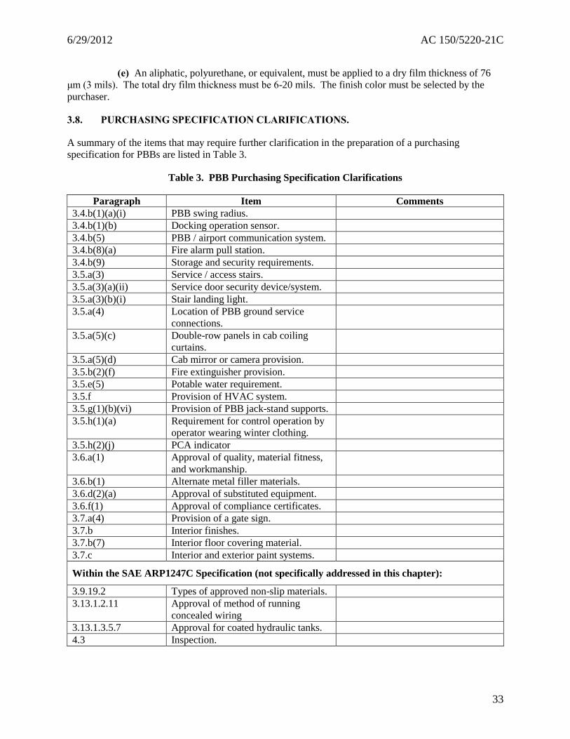
6/29/2012 AC 150/5220-21C
33
(e) An aliphatic, polyurethane, or equivalent, must be applied to a dry film thickness of 76
μm (3 mils). The total dry film thickness must be 6-20 mils. The finish color must be selected by the
purchaser.
3.8. PURCHASING SPECIFICATION CLARIFICATIONS.
A summary of the items that may require further clarification in the preparation of a purchasing
specification for PBBs are listed in Table 3.
Table 3. PBB Purchasing Specification Clarifications
Paragraph Item Comments
3.4.b(1)(a)(i) PBB swing radius.
3.4.b(1)(b) Docking operation sensor.
3.4.b(5) PBB / airport communication system.
3.4.b(8)(a) Fire alarm pull station.
3.4.b(9) Storage and security requirements.
3.5.a(3) Service / access stairs.
3.5.a(3)(a)(ii) Service door security device/system.
3.5.a(3)(b)(i) Stair landing light.
3.5.a(4) Location of PBB ground service
connections.
3.5.a(5)(c) Double-row panels in cab coiling
curtains.
3.5.a(5)(d) Cab mirror or camera provision.
3.5.b(2)(f) Fire extinguisher provision.
3.5.e(5) Potable water requirement.
3.5.f Provision of HVAC system.
3.5.g(1)(b)(vi) Provision of PBB jack-stand supports.
3.5.h(1)(a) Requirement for control operation by
operator wearing winter clothing.
3.5.h(2)(j) PCA indicator
3.6.a(1) Approval of quality, material fitness,
and workmanship.
3.6.b(1) Alternate metal filler materials.
3.6.d(2)(a) Approval of substituted equipment.
3.6.f(1) Approval of compliance certificates.
3.7.a(4) Provision of a gate sign.
3.7.b Interior finishes.
3.7.b(7) Interior floor covering material.
3.7.c Interior and exterior paint systems.
Within the SAE ARP1247C Specification (not specifically addressed in this chapter):
3.9.19.2 Types of approved non-slip materials.
3.13.1.2.11 Approval of method of running
concealed wiring
3.13.1.3.5.7 Approval for coated hydraulic tanks.
4.3 Inspection.

AC 150/5220-21C 6/29/2012
34
This page intentionally left blank.
6/29/2012 AC 150/5220-21C
35
CHAPTER 4. RAMPS
4.1. GENERAL.
a. The ramps covered in this chapter specifically relate to those portable devices used on an airport
apron that provide a continuous sloped surface from the ground to the aircraft doorsill height.
b. In many respects, the simple ramp is a good example of using universal design principles for
boarding aircraft. It can work with wheelchairs and boarding chairs, provides an easier path than stairs
for persons with limited mobility, and is a method that allows all passengers to board in the same manner.
4.2. SYSTEM DESCRIPTION.
Types of ramps discussed in this chapter:
a. Straight Ramp. This type of ramp provides a straight-line path from the ground to the aircraft
doorsill height (Figure 8a).
b. Switchback Ramp. This type of ramp provides a path in the form of switchbacks from the
ground to the aircraft doorsill height (Figure 8b).
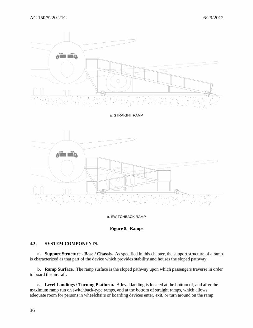
AC 150/5220-21C 6/29/2012
36
a. STRAIGHT RAMP
b. SWITCHBACK RAMP
Figure 8. Ramps
4.3. SYSTEM COMPONENTS.
a. Support Structure - Base / Chassis. As specified in this chapter, the support structure of a ramp
is characterized as that part of the device which provides stability and houses the sloped pathway.
b. Ramp Surface. The ramp surface is the sloped pathway upon which passengers traverse in order
to board the aircraft.
c. Level Landings / Turning Platform. A level landing is located at the bottom of, and after the
maximum ramp run on switchback-type ramps, and at the bottom of straight ramps, which allows
adequate room for persons in wheelchairs or boarding devices enter, exit, or turn around on the ramp
6/29/2012 AC 150/5220-21C
37
surface. Where straight ramps or switchback ramps are used to service regional airlines, a floating upper
bridge can be used that is lowered into the aircraft cabin. This floating upper bridge is not required to be
level.
4.4. PERFORMANCE.
a. Functions. The equipment must perform the following functions while maintaining a safe
distance from any moving part of the aircraft. If the device approaches within 12 in (30 cm) of any
moving part of the aircraft, the manufacturer must demonstrate to the satisfaction of the airline operator
that the device can perform all functions without undue risk of damage to the aircraft. The functions are
as follows:
(1) Provide a means for boarding wheelchair users and other passengers with mobility
impairments onto the ramp surface at ground level, as specified in 49 CFR § 38.23(c).
(2) Provide a path for transferring passengers from the ground to the elevated aircraft doorsill.
(3) Provide a suitable boarding chair, compatible with the device and the aircraft to be served,
meeting the requirements outlined in Chapter 6 of this AC, if specified by the purchaser.
b. Operational Standards.
(1) Movement. When passengers are occupying the ramp, provisions must be made to restrict
movement on the structure.
(2) Stability. The ramp must meet the requirements of SAE ARP1247, paragraph 3.13.1.9. The
device must be equipped with a stabilizing system for occupant safety mated to the aircraft doorsill.
(3) Level Landings. If level landings are present, the landing must provide space for a
wheelchair as specified in paragraph 2.2.b(1) of this document. The minimum width of the landing must
be equal to the width of the ramp leading to it, and the minimum area must be that as specified in
paragraph 2.2.c of this document.
(4) Ramp surface. The ramp surface must meet the requirements stated in paragraph 2.2.c of
this document. The ramp surface must be continuous and slip resistant, must not have protrusions from
the surface greater than 0.25 in (6.40 mm) high and must accommodate both four-wheel and three-wheel
mobility aids.
(5) Vibration. If applicable, the device must meet the requirements of SAE ARP1247,
paragraph 3.11 and MIL-STD-1472F, paragraph 5.8.4 (Vibration). For any discrepancies between the
documents, SAE ARP1247 takes precedence.
(6) Emergency Operations. If the device has an electronic method of raising or lowering the
ramp surface, the requirements of 49 CFR § 38.23(b)(3) must be met. Where there is a conflict with the
two documents, the ADA guidelines take precedence.
(a) Power or Equipment Failure. If applicable, the device must meet the requirements of
49 CFR § 38.23(b)(4).
(7) Storage / Security. All requirements needed to properly store and secure the device,
including those found in 49 CFR § 38.23(c)(7), must be supplied by the manufacturer.
AC 150/5220-21C 6/29/2012
38
4.5. DESIGN / DEVELOPMENT PHASE.
a. Attachments. When in use for boarding or alighting, the ramp must be firmly attached to the
vehicle so that it is not subject to displacement when loading or unloading a heavy power mobility aid.
No gap between vehicle and ramp will exceed 5/8 in (16 mm). [Reference 49 CFR § 38.23(c)(6)]
b. Service and Access. If the device is electrically powered, the requirements of SAE ARP1247,
paragraph 3.4.3 must be met.
c. Safety. The device must meet the requirements of SAE ARP1247, paragraph 3.8. All design
features intended to protect the equipment operator must provide similar protection to the passenger(s).
(1) Personnel Safety. The device must meet the requirements of SAE ARP1247, paragraph 3.9,
except as provided below.
(a) If highway transportability (defined as the capability of a self-propelled device to be
licensed for operation on public highways) is not specified by the purchaser, the provisions of SAE
ARP1247, paragraph 3.9.1 do not apply.
(b) If the device is not self-propelled, the provisions of SAE ARP1247, paragraphs 3.9.2
through 3.9.4 do not apply.
(2) Equipment Safety. The device must meet the requirements of SAE ARP1247, paragraph
3.10.
(a) Cushioning devices specified SAE ARP1247, paragraph 3.10.3 must be approved by the
purchaser.
(b) For any device not completely manually operated, a 5 lb (2 kg) BC rated fire extinguisher
must be mounted on the device at a location easily accessible to the operator.
(c) Stabilizing devices referred to in SAE ARP1247, paragraph 3.10.9.3 must be painted
chrome yellow, in accordance with AC 150/5210-5.
d. Mechanical / Structural Loading. The device must meet the requirements of SAE ARP1247,
paragraph 3.13.1.1, except as provided below.
(1) Platform Deflection. The ramp surface (not including the entrance ramp) must not deflect
more than 3 degrees (exclusive of ramp roll or pitch) in any direction between its unloaded position and
its position when loaded with 700 pounds applied through a 26 in by 26 in (0.66 m by 0.66 m) test pallet
at any point along the center of the pathway.
(2) Towing. The device must meet the requirements for tow hooks/towbar and towing placards,
found in SAE ARP5141, paragraph 6.
e. Electrical. If the ramp is only manually operated, then the requirements of this section do not
apply.
(1) General. The device must meet the requirements of SAE ARP1247, paragraph 3.13.1.2.
6/29/2012 AC 150/5220-21C
39
(a) When used for cranking engines of 30 horsepower (22 kW) or less, batteries referred to in
SAE ARP1247, paragraph 3.13.1.2.1 must be those recommended by the engine manufacturer.
(b) If highway transportability is specified, or otherwise specified by the purchaser, lighting
equipment must meet the provisions of SAE ARP1247, paragraphs 3.13.1.2.21 and 3.13.1.2.22. Lighting
must in all cases meet the requirements of AC 150/5210-5.
(c) A weatherproof lighting fixture producing a minimum of 5 foot-candles (54 lux) must be
attached to the device to illuminate the interface between the lift platform and the doorway of the aircraft.
(2) Battery Powered Devices.
(a) Batteries must be designed to have a minimum life of 3 years when maintained according
to the manufacturer’s instructions. For design purposes, a frequency of use of 1000 cycles per year must
be assumed.
(b) A self-contained battery charger with automatic voltage control must be provided. The
charging process will require the operator to connect a readily-accessible plug to a standard 110 or 220-
volt receptacle, as specified by the purchaser.
(c) The battery system must incorporate a battery condition gauge. If a low voltage
condition could result in higher amperage flow and motor burnout, then the status-monitoring device must
provide a time warning to the operator.
(3) Electromagnetic Interference. The equipment must meet the current issues of radio
suppression specification MIL-STD-461, Class 3D, Requirements for the Control of Electromagnetic
Interference Emissions and Susceptibility. It must be capable of operating through the entire amplitude
modulated aircraft radio frequency range of 75 MHz – 136 MHz.
f. Hydraulic and Pneumatic. If the ramp is only manually operated, than the requirements of this
section do not apply.
(1) The device must meet the requirements of SAE ARP1247, paragraph 3.13.1.3. Raising and
lowering of the lift must be accomplished by one person and through two or more hydraulic cylinders,
powered by an electric or engine driven pump. The system must incorporate a fail-safe hydraulic and/or
mechanical system designed to prevent lowering in the event of component failure.
(2) Hydraulic fluid must be as recommended by the manufacturers of the hydraulic system
components.
(3) The materials used for each hydraulic line must be consistent with its application. Fixed lines
must be made of high quality steel or stainless steel. Flexible lines must be used only where necessary.
(4) Hydraulic rams may be used to stabilize the device if all wheels remain firmly on the
pavement surface.
g. Engines and Related Equipment. If the ramp is only manually operated, than the requirements
of this section do not apply.
(1) General. The device must meet the requirements of SAE ARP1247, paragraph 3.13.1.4.
AC 150/5220-21C 6/29/2012
40
(a) The provisions of SAE ARP1247, paragraph 3.13.1.4.4 do not apply to engines of 30
horsepower (22 kW) or less.
(b) Alternators used on engines of 30 horsepower (22 kW) or less must be as recommended
by the engine manufacturer.
(c) Oil pressure switches are not be required on engines of 30 horsepower (22 kW) or less.
(d) The type of engine kill switch provided must be approved by the purchaser.
(e) Engines used to drive systems, other than the vehicle propulsion system, must be
equipped with a tachometer (green-lined within the correct operating RPM range and red-lined above this
range) or automatically governed to prevent over-revving.
(2) Fuel System. The device must meet the requirements of SAE ARP1247, paragraph 3.13.1.5.
(a) The provisions of SAE ARP1247, paragraph 3.13.1.5.1 do not apply to engines of 30
horsepower (22 kW) or less.
(b) The fuel tank must have a minimum capacity to store fuel needed for eight hours of
operation.
(c) Fuel tank fillers for engines of 30 horsepower (22 kW) or less must be as recommended
by the engine manufacturer, and must include a flame-arresting cap.
(d) Alternative fuels, such as bio-diesel, clean diesel, gaseous fuels (natural gas and liquid
petroleum gas), alcohols (methanol and ethanol), Jet A, and reformulated gasoline may be used to power
self-propelled lift devices. Equipment modifications to allow the use of such fuels must conform to
manufacturer specifications.
(3) Exhaust System. The device must meet the requirements of SAE ARP1247, paragraph
3.13.1.6. Engine exhaust systems must be provided with flame and spark arrestors.
h. Self-Propelled Vehicles. If the ramp is only manually operated, than the requirements of this
section do not apply. Otherwise, the device must meet the requirements of SAE ARP1247, paragraph
3.13.1.7.
(1) Vehicle Cabs. On vehicles equipped with an enclosed operator’s cab, the cab must meet the
requirements of SAE ARP1247, paragraph 3.13.1.7.3.
(2) Passenger Van Body. On vehicles equipped with an enclosed passenger van body, the
requirements of SAE ARP5141, paragraph 4.2.6 must be met.
(3) HVAC System. If an HVAC system is specified by the purchaser, enclosed lift systems must
meet the requirements of SAE J1503 and FMVSS No. 103. In sections where the two documents may
conflict, FMVSS No. 103 takes precedence.
(4) Design Speed. The device must meet the requirements of SAE ARP5140, paragraph 4.1.5,
or as specified by the purchaser.
(5) Braking Systems.
6/29/2012 AC 150/5220-21C
41
(a) Braking systems for vehicles with a maximum speed of 20 mph (32 km/h) or more must
meet the requirements of SAE ARP1247, paragraph 3.13.1.7.2.
(b) Braking systems for vehicles with a maximum speed of less than 20 mph (32 km/h) must
meet the requirements of Title 49 CFR, § 393.41 and 393.52. The maximum stopping distance in feet
must be equal to the design speed in mph (in meters must be equal to the design speed in km/h).
i. Instruments and Controls. If the ramp is only manually operated, than the requirements of this
section do not apply. Otherwise, the device must meet the requirements of 49 CFR § 38.23(b)(2)(i),
38.23(b)(2)(ii), and SAE ARP1247, paragraph 3.13.1.8. Where there is a conflict with the two
documents, the DOT regulations take precedence.
(1) If approved by the purchaser, transmission selector levers may move and operate in the
direction of travel of the device. Inclusion or deletion of “Park” position will be as specified by the
purchaser.
(2) Unless otherwise specified by the purchaser, controls must be designed for satisfactory
operation when the operator is wearing heavy arctic-type gloves and overshoes.
4.6. CONSTRUCTION / PRODUCTION PHASE.
a. Workmanship. The device must meet the requirements of SAE ARP1247, paragraph 3.13.7.
b. Materials. The device must meet the requirements of SAE ARP1247, paragraph 3.13.2.
(1) Moisture and Fungus Resistance. The device must meet the requirements of SAE
ARP1247, paragraph 3.13.4.
(2) Corrosion of Metal Parts. The device must meet the requirements of SAE ARP1247,
paragraph 3.13.5.
c. Parts.
(1) Standard and Commercial Parts. The device must meet the requirements of SAE
ARP1247, paragraph 3.13.3.
(2) Interchangeability and Replaceability. The device must meet the requirements of SAE
ARP1247, paragraph 3.13.6.
4.7. POST-PRODUCTION PHASE.
a. Identification and Marking. The device must meet the requirements of SAE ARP1247,
paragraph 3.13.9. If the ramp is self-propelled, the shifting diagram placard specified in SAE ARP1247,
paragraph 3.13.9.6, may be provided in a medium other than metal if designated to last for the total life of
the equipment. In addition, the device must be provided with a permanently affixed placard identifying
the maximum number of passengers and maximum weight capacity of the lifting platform or ramp. In the
event that identification and marking guidance differs between SAE ARP1247 and AC 150/5210-5, AC
150/5210-5 takes precedence.
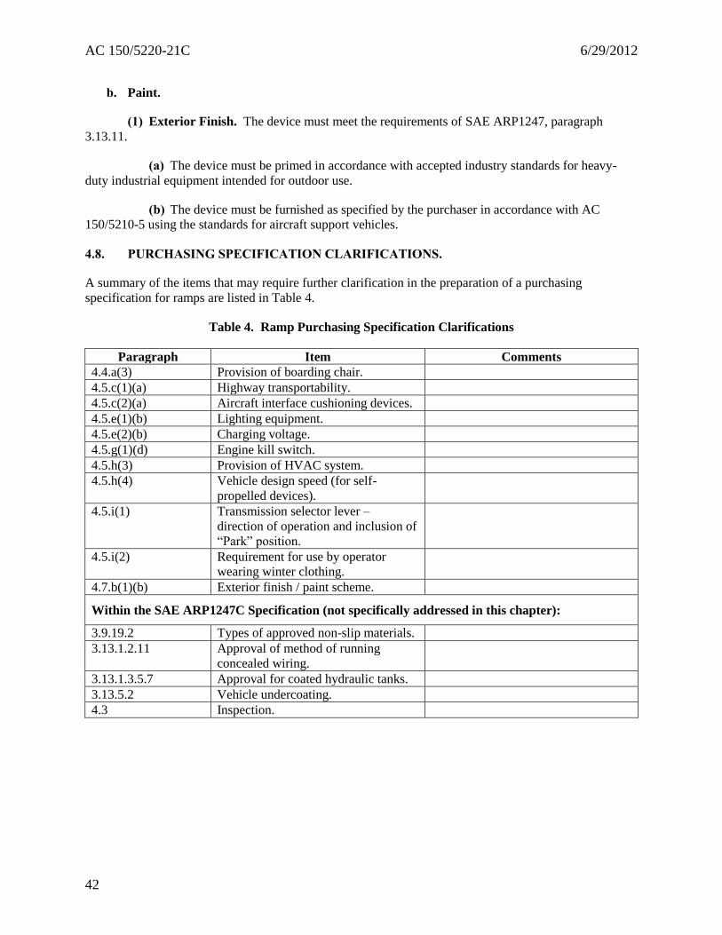
AC 150/5220-21C 6/29/2012
42
b. Paint.
(1) Exterior Finish. The device must meet the requirements of SAE ARP1247, paragraph
3.13.11.
(a) The device must be primed in accordance with accepted industry standards for heavy-
duty industrial equipment intended for outdoor use.
(b) The device must be furnished as specified by the purchaser in accordance with AC
150/5210-5 using the standards for aircraft support vehicles.
4.8. PURCHASING SPECIFICATION CLARIFICATIONS.
A summary of the items that may require further clarification in the preparation of a purchasing
specification for ramps are listed in Table 4.
Table 4. Ramp Purchasing Specification Clarifications
Paragraph Item Comments
4.4.a(3) Provision of boarding chair.
4.5.c(1)(a) Highway transportability.
4.5.c(2)(a) Aircraft interface cushioning devices.
4.5.e(1)(b) Lighting equipment.
4.5.e(2)(b) Charging voltage.
4.5.g(1)(d) Engine kill switch.
4.5.h(3) Provision of HVAC system.
4.5.h(4) Vehicle design speed (for self-
propelled devices).
4.5.i(1) Transmission selector lever –
direction of operation and inclusion of
“Park” position.
4.5.i(2) Requirement for use by operator
wearing winter clothing.
4.7.b(1)(b) Exterior finish / paint scheme.
Within the SAE ARP1247C Specification (not specifically addressed in this chapter):
3.9.19.2 Types of approved non-slip materials.
3.13.1.2.11 Approval of method of running
concealed wiring.
3.13.1.3.5.7 Approval for coated hydraulic tanks.
3.13.5.2 Vehicle undercoating.
4.3 Inspection.
6/29/2012 AC 150/5220-21C
43
CHAPTER 5. LIFTS
5.1. GENERAL.
a. The lift equipment covered in this chapter specifically relates to devices that provide an elevating
platform allowing the transfer of a person with disability or mobility impairment from the airport apron
up to the aircraft door. Lift devices used anywhere else or for any other reason are not covered in this
chapter. The term aircraft in this chapter refers to those with door sill heights of 60 in (1.50 m) and
above.
b. For the purposes of this specification, the two terms used to describe the operation of the lift
mechanism are manually powered or motorized (via electric, hydraulic, or pneumatic means). The three
terms used to describe the means by which a device transports the operator or passengers a given
horizontal distance are manually powered, towed, or self-propelled (via electric motor or internal
combustion engine). The purchaser will specify the type of lift mechanism and transport operation
needed.
5.2. SYSTEM DESCRIPTION.
Types of lifts discussed in this chapter:
a. Elevating Transport Vehicle. A self-propelled vehicle capable of carrying many passengers and
attendants in an enclosed cab, containing a chassis-mounted lift.
b. Modified Lift. Equipment originally used for cargo but modified for passenger transport (e.g. a
converted forklift or scissor lift).
c. Elevating Boarding Stairs. Devices that allow a platform to slide up a boarding stair incline.
This AC will not focus on this type of device.
5.3. SYSTEM COMPONENTS.
a. Support Structure - Base / Chassis. The support structure of a lifting device is characterized as
that part of the device which houses the lifting mechanism and platform.
b. Lifting Mechanism. The lifting mechanism is the part of the device that functions to elevate or
lower the platform. The lifting mechanism contains working and non-working parts. Working parts are
characterized as those items that move and support the load, such as cables, pulleys, and shafts. Non-
working parts are characterized as being in the lifting frame and attached, non-moving hardware.
c. Platform. The platform is a horizontal surface that is raised or lowered between ground level
and the aircraft door. As used herein, the platform refers to all surfaces traversed by the passenger using a
wheelchair in boarding the aircraft.
5.4. PERFORMANCE.
a. Functions. The equipment must perform the following functions while maintaining a safe
distance from any moving part of the aircraft. If the device approaches within 12 in (30 cm) of any
moving part of the aircraft, the manufacturer must demonstrate to the satisfaction of the airline operator
AC 150/5220-21C 6/29/2012
44
that the device can perform all functions without undue risk of damage to the aircraft. The functions are
as follows:
(1) Provide a means for boarding wheelchair users and other passengers with mobility
impairments (persons using walkers, crutches, canes or braces or who otherwise have difficulty using
steps) onto the lifting platform at ground level, as specified in 49 CFR § 38.23(b).
(2) Elevate the lifting platform carrying the passenger(s) and attendant(s) to the aircraft doorsill
height.
(3) Provide a means for transferring passengers using wheelchairs from the elevated lift platform
or ramp to and from the aircraft doorsill.
(4) Provide a suitable boarding chair, compatible with the device and the aircraft to be served,
meeting the requirements outlined in Chapter 6 of this AC, if specified by the purchaser.
(5) Provide a stairway for the boarding of other passengers, if specified by the purchaser.
(6) Provide protection from wind and precipitation to passengers, if specified by the purchaser.
(7) Provide transportation between the terminal and the aircraft, if specified by the purchaser.
b. Operational Standards.
(1) Platform Movement.
(a) With Passengers. When lowering or lifting an occupant, passengers must not be
subjected to the following changes in movement:
Velocity in excess of 6 in/s (0.15 m/s) in any direction,
Acceleration in excess of 10 ft/s2 (3 m/s
2) in any direction, and
Jerk in excess of 8 ft/s3 (2.40 m/s
3) in any direction.
(b) Without Passengers. Movement standards for all operations are the same as previously
described, except during deployment and stowage of the device. For motorized lift mechanisms during
deployment or stowage the velocity must not exceed 12 in/s (0.30 m/s). Manually deployed or stowed
lifts have no movement limitations during deployment or stowage.
(2) Stability. The device must meet the requirements of SAE ARP1247, paragraph 3.13.1.9.
(a) The device must be equipped with a stabilizing system for occupant safety while the unit
is mated to the aircraft doorsill.
(b) For self-propelled devices requiring stabilizers to meet the requirements of this
specification, the requirements of SAE ARP5141, paragraph 4.2.5 must be met.
(3) Noise and Vibration. The device must meet the requirements of SAE ARP1247, paragraph
3.11 and FAA HF-STD-001, paragraph 13.5 (Noise) and MIL-STD-1472F, paragraph 5.8.4 (Vibration).
For any discrepancies between the documents, SAE ARP1247 takes precedence.
6/29/2012 AC 150/5220-21C
45
(4) Operability. Lifts must be capable of 45 minutes of continuous operation, consisting of any
possible combination of passenger loading and maneuvering cycles at full load within the temperature
ranges specified in paragraph 2.3.e.(1) of this AC. For passenger loading, full load must be considered to
be applied during the ascent phase only.
(5) Emergency Operations. The device must meet the requirements of 49 CFR § 38.23(b)(3))
and SAE ARP1247, paragraph 3.9.11. Where there is a conflict with the two documents, the DOT
regulations take precedence.
(a) Power or Equipment Failure. The device must meet the requirements of 49 CFR §
38.23(b)(4)).
(6) Storage / Security. All requirements needed to properly store and secure the device must be
supplied by the manufacturer.
5.5. DESIGN / DEVELOPMENT PHASE.
a. The device must meet the requirements of SAE ARP1247, paragraph 3.13, except as modified
herein.
(1) Platform.
(a) Edge Barriers. Barriers must be provided to prevent the possibility of a passenger or
mobility aid from traveling beyond the edge of a platform, except at the entry and exit points, and then
only when the passenger is entering or exiting the lift. Platform edge barriers for lifts must meet the
requirements of 49 CFR § 38.23(b)(5)).
(b) Surface. The platform surface must meet the requirements of 49 CFR § 38.23(b)(6)).
(c) Gaps. Gaps in the platform surface must meet the requirements of 49 CFR §
38.23(b)(7)).
(d) Entrance Ramp. The platform entrance ramp must meet the requirements of 49 CFR §
38.23(b)(8)).
(e) Boarding Direction. The lift must permit both inboard and outboard facing of
wheelchair and mobility aid users, as specified in 49 CFR § 38.23(b)(11)).
(f) The interior width of the platform must be compatible with the boarding chair to be used
and aircraft to be served.
(2) Passenger Restraints.
(a) If specified by the purchaser, lift platforms must include a system to immobilize each
wheelchair it is designed to simultaneously transport. The system must be easily operated by the
attendant or equipment operator.
(3) Service and Access. The device must meet the requirements of SAE ARP1247, paragraph
3.4.3.
AC 150/5220-21C 6/29/2012
46
b. Safety. The device must meet the requirements of SAE ARP1247, paragraph 3.8. All design
features intended to protect the equipment operator must provide similar protection to the passenger(s).
(1) Personnel Safety. The device must meet the requirements of SAE ARP1247, paragraph 3.9,
except as provided below.
(a) If highway transportability, defined as the capability (of a self-propelled device) to be
licensed for operation on public highways, is not specified by the purchaser, the provisions of SAE
ARP1247, paragraph 3.9.1 do not apply.
(b) If the device is not self-propelled, the provisions of SAE ARP1247, paragraphs 3.9.2
through 3.9.4 do not apply.
(2) Equipment Safety. The device must meet the requirements of SAE ARP1247, paragraph
3.10.
(a) Cushioning devices specified in SAE ARP1247, paragraph 3.10.3 must be approved by
the purchaser.
(b) For any device not completely manually operated, a 5 lb (2 kg) BC-rated fire extinguisher
must be mounted on the device at a location easily accessible to the operator.
(c) Stabilizing devices referred to in SAE ARP1247, paragraph 3.10.9.3 must be painted
chrome yellow in accordance with AC 150/5210-5.
(d) Machine guarding. Machine guarding must be appropriately installed where personnel
have an exposure to portions of the device that can crush, fall on, or otherwise harm them while the
equipment is in operation.
c. Mechanical / Structural Loading. The device must meet the requirements of SAE ARP1247,
paragraph 3.13.1.1, except as provided below.
(1) Factor of Safety. Working parts on the lift mechanism, such as cables (wire rope), pulleys,
and shafts, must have a minimum factor of safety of 10, based on the ultimate strength of the material.
(2) Platform Deflection. The lift platform (not including the entrance ramp) must not deflect
more than 3 degrees (exclusive of vehicle roll or pitch) in any direction between its unloaded position and
its position when loaded with 700. lbs (318 kg) applied through a 26 in by 26 in (0.66 m by 0.66 m) test
pallet at the centroid of the platform.
(3) Towing. The device must meet the requirements for tow hooks/towbar and towing placards
found in SAE ARP5141, paragraph 6.
d. Electrical.
(1) General. The device must meet the requirements of SAE ARP1247, paragraph 3.13.1.2.
(a) When used for cranking engines of 30 horsepower (22 kW) or less, batteries referred to in
SAE ARP1247, paragraph 3.13.1.2.1 must be those recommended by the engine manufacturer.
6/29/2012 AC 150/5220-21C
47
(b) If highway transportability is specified, or otherwise specified by the purchaser, lighting
equipment must meet the provisions of SAE ARP1247, paragraphs 3.13.1.2.21 and 3.13.1.2.22. Lighting
must in all cases meet the requirements of AC 150/5210-5.
(c) A weatherproof lighting fixture producing a minimum of 5 foot-candles (54 lux) must be
attached to the device to illuminate the interface between the lift platform and the doorway of the aircraft.
(2) Battery Powered Devices.
(a) Batteries must be designed to have a minimum life of 3 years when maintained according
to the manufacturer’s instructions. For design purposes, a frequency of use of 1000 cycles per year must
be assumed.
(b) A self-contained battery charger with automatic voltage control must be provided. The
charging process will require the operator only to connect a readily-accessible plug to a standard 110 or
220-volt receptacle, as specified by the purchaser.
(c) The battery system must incorporate a battery condition gauge. If a low voltage
condition could result in higher amperage flow and motor burnout, then the status-monitoring device must
provide a time warning to the operator.
(3) Electromagnetic Interference. The equipment must meet the current issues of radio
suppression specification MIL-STD-461, Class 3D, Requirements for the Control of Electromagnetic
Interference Emissions and Susceptibility. It must be capable of operating through the entire amplitude
modulated aircraft radio frequency range of 75 MHz – 136 MHz.
e. Hydraulic and Pneumatic. The device must meet the requirements of SAE ARP1247,
paragraph 3.13.1.3. Raising and lowering of the lift must be accomplished by one person and through
two or more hydraulic cylinders powered by an electric or engine driven pump. The system must
incorporate a fail-safe hydraulic and/or mechanical system (or lock-out mechanism) designed to prevent
lowering in the event of component failure. The system/lock-out mechanism must be readily accessible
from the operator’s normal operating position.
(1) Hydraulic fluid must be as recommended by the manufacturers of the hydraulic system
components.
(2) The materials used for each hydraulic line must be consistent with its application. Fixed lines
must be made of high quality steel or stainless steel. Flexible lines must be used only where necessary.
(3) Hydraulic rams may be used to stabilize the device if all wheels remain firmly on the
pavement surface.
f. Engines and Related Equipment.
(1) General. The device must meet the requirements of SAE ARP1247, paragraph 3.13.1.4.
(a) The provisions of SAE ARP1247, paragraph 3.13.1.4.4 do not apply to engines of 30
horsepower (22 kW) or less.
(b) Alternators used on engines of 30 horsepower (22 kW) or less must be as recommended
by the engine manufacturer.
AC 150/5220-21C 6/29/2012
48
(c) Oil pressure switches are not be required on engines of 30 horsepower (22 kW) or less.
(d) The type of engine kill switch must be approved by the purchaser.
(e) Engines used to drive systems, other than the vehicle propulsion system, must be
equipped with a tachometer (green-lined within the correct operating RPM range and red-lined above this
range) or automatically governed to prevent over-revving.
(2) Fuel System. The device must meet the requirements of SAE ARP1247, paragraph 3.13.1.5.
(a) The provisions of SAE ARP1247, paragraph 3.13.1.5.1, do not apply to engines of 30
horsepower (22 kW) or less.
(b) The fuel tank must have a minimum capacity for eight hours of operation.
(c) Fuel tank fillers for engines of 30 horsepower (22 kW) or less must be as recommended
by the engine manufacturer but must include a flame-arresting cap.
(d) Alternative fuels, such as bio-diesel, clean diesel, gaseous fuels (natural gas and liquid
petroleum gas), alcohols (methanol and ethanol), Jet A, and reformulated gasoline may be used to power
self-propelled lift devices. Equipment modifications to allow the use of such fuels must conform to
manufacturer specifications.
(3) Exhaust System. The device must meet the requirements of SAE ARP1247, paragraph
3.13.1.6. Engine exhaust systems must be provided with flame and spark arrestors.
g. Self-Propelled Vehicles. The device must meet the requirements of SAE ARP1247, paragraph
3.13.1.7.
(1) Vehicle Cabs. On vehicles equipped with an enclosed operator’s cab, the cab must meet the
requirements of SAE ARP1247, paragraph 3.13.1.7.3.
(2) Passenger Van Body. On vehicles equipped with an enclosed passenger van body, the
requirements of SAE ARP5141, paragraph 4.2.6, must be met.
(3) HVAC System. If an HVAC system is specified by the purchaser, enclosed lift systems must
meet the requirements of SAE J1503 and FMVSS No. 103. In sections where the two documents may
conflict, FMVSS No. 103 takes precedence.
(4) Design Speed. The device must meet the requirements of SAE ARP5140, paragraph 4.1.5,
or as specified by the purchaser.
(5) Braking Systems.
(a) Braking systems for vehicles with a maximum speed of 20 mph (32 km/h) or more must
meet the requirements of SAE ARP1247, paragraph 3.13.1.7.2.
(b) Braking systems for vehicles with a maximum speed of less than 20 mph (32 km/h) must
meet the requirements of Title 49 CFR, § 393.41 and 393.52. The maximum stopping distance in feet
must be equal to the design speed in mph (in meters must be equal to the design speed in km/h).
6/29/2012 AC 150/5220-21C
49
h. Instruments and Controls. The device must meet the requirements of 49 CFR § 38.23(b)(2)(i)
and 38.23(b)(2)(ii)), and SAE ARP1247, paragraph 3.13.1.8. Where there is a conflict with the two
documents, the DOT regulations take precedence.
(1) If approved by the purchaser, transmission selector levers may move and operate in the
direction of travel of the device. Inclusion or deletion of “Park” position will be as specified by the
purchaser.
(2) Unless otherwise specified by the purchaser, controls must be designed for satisfactory
operation when the operator is wearing heavy arctic-type gloves and overshoes.
5.6. CONSTRUCTION / PRODUCTION PHASE.
a. Workmanship. The device must meet the requirements of SAE ARP1247, paragraph 3.13.7.
b. Materials. The device must meet the requirements of SAE ARP1247, paragraph 3.13.2.
(1) Moisture and Fungus Resistance. The device must meet the requirements of SAE
ARP1247, paragraph 3.13.4.
(2) Corrosion of Metal Parts. The device must meet the requirements of SAE ARP1247,
paragraph 3.13.5.
c. Parts.
(1) Standard and Commercial Parts. The device must meet the requirements of SAE
ARP1247, paragraph 3.13.3.
(2) Interchangeability and Replaceability. The device must meet the requirements of SAE
ARP1247, paragraph 3.13.6.
5.7. POST-PRODUCTION PHASE.
a. Identification and Marking. The device must meet the requirements of SAE ARP1247,
paragraph 3.13.9. The shifting diagram placard specified in SAE ARP1247, paragraph 3.13.9.6 may be
provided in a medium other than metal if designated to last for the total life of the equipment. In addition,
the device must be provided with a permanently affixed placard identifying the maximum number of
passengers and maximum weight capacity of the lifting platform or ramp. In the event that identification
and marking guidance differs between SAE ARP1247 and AC 150/5210-5, AC 150/5210-5 takes
precedence.
(1) The platform may be marked to indicate a preferred standing position.
b. Paint.
(1) Exterior Finish. The device must meet the requirements of SAE ARP1247, paragraph
3.13.11.
(a) The device must be primed in accordance with accepted industry standards for heavy-
duty industrial equipment intended for outdoor use.

AC 150/5220-21C 6/29/2012
50
(b) The device must be furnished as specified by the purchaser, in accordance with AC
150/5210-5, using the standards for aircraft support vehicles.
5.8. PURCHASING SPECIFICATION CLARIFICATIONS.
A summary of the items that may require further clarification in the preparation of a purchasing
specification for lifts are listed in Table 5.
Table 5. Lift Purchasing Specification Clarifications
Paragraph Item Comments
5.1.b Lift mechanism and transport method.
5.4.a(4) Provision of boarding chair.
5.4.a(5) Provision of stairway.
5.4.a(6) Provision of weather protection.
5.4.a(7) Provision of transportation between
terminal and aircraft.
5.5.a(2)(a) Provision of wheelchair
immobilization system.
5.5.b(2)(a) Aircraft interface cushioning devices.
5.5.d(2)(b) Charging voltage.
5.5.f(1)(d) Engine kill switch.
5.5.g(3) Provision of HVAC system.
5.5.g(4) Vehicle design speed (for self-
propelled devices).
5.5.h(1) Transmission selector lever –
direction of operation and inclusion of
“Park” position.
5.5.h(2) Requirement for use by operator
wearing winter clothing.
5.7.b(1)(b) Exterior finish / paint scheme.
Within the SAE ARP1247C Specification (not specifically addressed in this chapter):
3.9.19.2 Types of approved non-slip materials.
3.13.1.2.11 Approval of method of running
concealed wiring.
3.13.1.3.5.7 Approval for coated hydraulic tanks.
3.13.5.2 Vehicle undercoating.
4.3 Inspection.
6/29/2012 AC 150/5220-21C
51
CHAPTER 6. AIRCRAFT BOARDING CHAIRS
6.1. GENERAL.
a. This chapter outlines the performance and technical design specifications for aircraft boarding
chairs. Aircraft boarding chairs are those devices used to transfer passengers from their wheelchair or
other apparatus to their seat in the aircraft cabin. This specification does not apply to other types of
devices, such as on-board chairs used for in-flight mobility, stair-climbing wheelchairs, or wheelchairs
used for mobility within the airport terminal.
b. The basis for this chapter is the technical paper produced by the U.S. Access Board on Guidelines
for Aircraft Boarding Chairs. Additional requirements and clarifications have been added where
necessary.
6.2. PERFORMANCE.
a. Functions. The chair must be able to provide a means for transferring passengers from their
personal wheelchair to their seat inside the aircraft, using any of the other boarding equipment described
in this AC.
b. Operational Standards.
(1) Capacity. The aircraft boarding chair must be able to support a passenger weighing 723 lbs
(328 kg). [Source: U.S. Access Board Guidelines for Aircraft Boarding Chairs (1987), paragraph 4.1.c.]
(2) Stability. The boarding device must meet the provisions of the U.S. Access Board
Guidelines for Aircraft Boarding Chairs (1987), paragraph 4.1.d, with the exception that the downward
force must be 350 lbs (159 kg) instead of the 241 lbs (109 kg) specified.
(3) Turning. The boarding device must meet the provisions of the U.S. Access Board
Guidelines for Aircraft Boarding Chairs (1987), paragraph 3.1.f.
(4) Ease of Movement. The boarding device must meet the provisions of the U.S. Access Board
Guidelines for Aircraft Boarding Chairs (1987), paragraph 3.1.g.
(5) Ease of Transfer. The boarding device must meet the provisions of the U.S. Access Board
Guidelines for Aircraft Boarding Chairs (1987), paragraph 3.1.h.
(6) Braking. The boarding device must be equipped with a braking (deadman) feature/lever that
stops all forward and backward progress when the feature/lever is released by the operator.
(7) Vibration. The boarding device must meet the provisions of the U.S. Access Board
Guidelines for Aircraft Boarding Chairs (1987), paragraph 3.1.i.
(8) Alignment. The boarding device must meet the provisions of the U.S. Access Board
Guidelines for Aircraft Boarding Chairs (1987), paragraph 3.1.j.
(9) Independent Mobility. The boarding device must meet the provisions of the U.S. Access
Board Guidelines for Aircraft Boarding Chairs (1987), paragraph 3.1.k.

AC 150/5220-21C 6/29/2012
52
(10) Storage. The boarding device must meet the provisions of the U.S. Access Board
Guidelines for Aircraft Boarding Chairs (1987), Section 3.4.
6.3. DESIGN / DEVELOPMENT PHASE.
a. Overall Dimensions. The boarding device must meet the provisions of the U.S. Access Board
Guidelines for Aircraft Boarding Chairs (1987), paragraph 4.1.a.
b. Overall Weight. The boarding device must meet the provisions of the U.S. Access Board
Guidelines for Aircraft Boarding Chairs (1987), paragraph 4.1.b.
c. Safety.
(1) Passenger Safety features must be designed into the boarding device with the knowledge that
the passenger, for example, may not have tactile sensations to provide feedback when pressure points
exist, may not have trunk control to maintain good posture when being moved in the device, and may
experience muscle spasms that will cause erratic motion at any time.
(2) Boarding Agent Safety features must be designed into the boarding device with the
knowledge that the agent will be responsible for the passenger transfers to and from the device as well as
moving the device to and from the aircraft seat. The boarding device must be designed so that all lifting
and positioning operations to be performed by the boarding agent can be done in a way that will minimize
the risk of injury. The particular operations that should be considered are manual dependent transfers
(two boarding agents lifting the passenger to or from the boarding device) and movement of the occupied
device from the transfer area to a position for transfer to the aircraft seat (this includes, for example,
turning the device and crossing the aircraft door threshold). [Source: Reference Guidelines for Aircraft
Boarding Chairs (1987), Access Board]
(3) Powered Boarding Equipment should be designed with special consideration for safety of
both the operator and the passenger. There should be no possibility of inadvertent operation, or of a
person accidentally putting a part of their body in a place where operation of the device may cause injury.
(4) Posture. The boarding device must meet the provisions of the U.S. Access Board Guidelines
for Aircraft Boarding Chairs (1987), paragraph 3.2.a. Note: If the device does not allow the passenger to
maintain their proper posture, the restraints will not function as designed and overall safety will be
compromised.
(5) Support. The boarding device must meet the provisions of the U.S. Access Board
Guidelines for Aircraft Boarding Chairs (1987), paragraph 3.2.b. The full anthropomorphic range (with
particular attention to the lower and upper limits) is that which is defined in paragraph 2.2.a of this AC.
(6) Restraints. The boarding device must meet the provisions of the U.S. Access Board
Guidelines for Aircraft Boarding Chairs (1987), paragraph 3.2.c. Provisions should be made so that
maintenance personnel can easily replace or repair restraints/straps that may wear out or become
damaged.
(7) Hinges and Locking Mechanisms. The boarding device must meet the provisions of the
U.S. Access Board Guidelines for Aircraft Boarding Chairs (1987), paragraphs 3.1.l. and 3.2.d.
(8) Adjustability. The boarding device must meet the provisions of the U.S. Access Board
Guidelines for Aircraft Boarding Chairs (1987), paragraph 4.1.f.
6/29/2012 AC 150/5220-21C
53
(9) Protective Features. The boarding device must meet the provisions of the U.S. Access
Board Guidelines for Aircraft Boarding Chairs (1987), paragraph 4.1.i.
d. Boarding Chair Features.
(1) Seating. The boarding device must meet the provisions of the U.S. Access Board Guidelines
for Aircraft Boarding Chairs (1987), Section 4.2.
(2) Backrests. The boarding device must meet the provisions of the U.S. Access Board
Guidelines for Aircraft Boarding Chairs (1987), Section 4.3.
(3) Headrests. The boarding device must meet the provisions of the U.S. Access Board
Guidelines for Aircraft Boarding Chairs (1987), Section 4.4.
(4) Armrests. The boarding device must meet the provisions of the U.S. Access Board
Guidelines for Aircraft Boarding Chairs (1987), Section 4.5.
(5) Gripping Surfaces. The boarding device must meet the provisions of the U.S. Access Board
Guidelines for Aircraft Boarding Chairs (1987), Section 4.6.
(6) Restraints. The boarding device must meet the provisions of the U.S. Access Board
Guidelines for Aircraft Boarding Chairs (1987), Section 4.7.
(7) Footrests. The boarding device must meet the provisions of the U.S. Access Board
Guidelines for Aircraft Boarding Chairs (1987), Section 4.8.
e. Mechanical / Structural Loading. The device must meet the provisions of the U.S. Access
Board Guidelines for Aircraft Boarding Chairs (1987), paragraph 4.1.e.
6.4. CONSTRUCTION / PRODUCTION PHASE.
a. Workmanship. The device must meet the provisions of SAE ARP1247, paragraph 3.13.7, and
the manufacturer must install all equipment, materials, specialties, etc., in accordance with the best
engineering practice and standards for this type of work.
b. Materials. The device must meet the provisions of SAE ARP1247, paragraph 3.13.2, the U.S.
Access Board Guidelines for Aircraft Boarding Chairs (1987), paragraph 4.1.h.
(1) Moisture and Fungus Resistance. The device must meet the provisions of SAE ARP1247,
paragraph 3.13.4.
(2) Corrosion of Metal Parts. The device must meet the provisions of SAE ARP1247,
paragraph 3.13.5.
c. Parts.
(1) Standard and Commercial Parts. The device must meet the provisions of SAE ARP1247,
paragraph 3.13.3, and the U.S. Access Board Guidelines for Aircraft Boarding Chairs (1987), paragraph
3.3.g.
(2) Interchangeability and Replaceability. The device must meet the provisions of SAE
ARP1247, paragraph 3.13.6, and the U.S. Access Board Guidelines for Aircraft Boarding Chairs (1987),
AC 150/5220-21C 6/29/2012
54
paragraph 3.3.e. Removable parts must meet the provisions of the U.S. Access Board Guidelines for
Aircraft Boarding Chairs (1987), paragraph 4.1.g.
6.5. POST-PRODUCTION PHASE.
a. Identification and Marking. The purchaser will specify the identification and marking
standards. In addition, the device must be provided with a permanently affixed placard identifying the
maximum weight capacity of the chair.
b. Paint. The exterior finish of the device must be primed in accordance with accepted industry
standards.
6.6. PURCHASING SPECIFICATION CLARIFICATIONS.
A summary of the items that may require further clarification in the preparation of a purchasing
specification for aircraft boarding chairs are listed in Table 6.
Table 6. Aircraft Boarding Chair Purchasing Specification Clarifications
Paragraph Item Comments
6.5.a Identification / Marking / Paint
scheme.
Within the SAE ARP1247C Specification (not specifically addressed in this chapter):
3.9.19.2 Types of approved non-slip materials.
3.13.1.2.11 Approval of method of running
concealed wiring.
3.13.1.3.5.7 Approval for coated hydraulic tanks.
3.13.5.2 Vehicle undercoating.
4.3 Inspection.
6/29/2012 AC 150/5220-21C
Appendix A
55
APPENDIX A. ABBREVIATIONS AND ACRONYMS
ABA Architectural Barriers Act
AC Advisory Circular
ACAA Air Carrier Access Act
ADA Americans with Disabilities Act
ADAAG Americans with Disabilities Act Accessibility Guidelines
AIR Aerospace Information Report
AISC American Institute of Steel Construction
Amp ampere
ANSI American National Standards Institute
ARP Aerospace Recommended Practice
ASTM American Society for Testing and Materials
ATA Air Transport Association
CAN/CGSB Canadian General Standards Board
CFR Code of Federal Regulations
DoD Department of Defense
DOT Department of Transportation
FAA Federal Aviation Administration
FMVSS Federal Motor Vehicle Safety Standard
FR Federal Register
GFI Ground Fault Interrupter
HMI Human Machine Interface
HVAC Heating, Ventilation, and Air Conditioning
Hz hertz
IBC International Building Code
IN/S Inches per Second

AC 150/5220-21C 6/29/2012
Appendix A
56
ISO International Organization for Standardization
Kg kilogram
KM/H Kilometers per hour
kW kilowatt
Lbf pounds of force
Lb pound
M meter
M/S Meters per second
MHz megahertz
mm millimeter
MPH Miles per hour
N newtons
NEC National Electrical Code
NEMA National Electrical Manufacturers Association
NFPA National Fire Prevention Association
OSHA Occupational Safety and Health Administration
PCA preconditioned air
PBB passenger boarding bridge
Psf Pounds per Square Foot
RPM Revolutions per minute
SAE Society of Automotive Engineers
SSPC Society for Protective Coatings
UFAS Uniform Federal Accessibility Standard
UL Underwriters Laboratories
μm micrometer
6/29/2012 AC 150/5220-21C
Appendix B
57
APPENDIX B. GLOSSARY
Aircraft Boarding Chair – Narrow, wheelchair-like devices used to transport disabled passengers between
the airport terminal and the aircraft seat.
Boarding bridge – an enclosed, movable connector which extends from an airport terminal gate to an
airplane, thereby enabling passengers to board and disembark without having to go outside.
Dead Loads – Includes the weight of the structure and all permanently attached equipment and
accessories.
Deadman – Type of switch that stops or slows motion when released by the operator.
Deplane – to disembark from an aircraft.
Disability – see “person with a disability”.
Enplane – to board an aircraft.
Lift (aircraft) – a device used to elevate a passenger with a disability to the aircraft doorsill eliminating
the need to use stairs.
Live Loads – Includes loads due to intended use and occupancy of an area, moveable equipment and
partitions (e.g., loads associated with movement of the boarding device), and vehicle loads (e.g.,
motorized wheel chairs, small baggage tugs).
Manual wheelchair – Manual wheelchairs are those that require human power to move them. There are
three types of manual wheelchair: self-propelled, attendant-propelled, and wheelbase. Many manual
wheelchairs can be folded for storage or placement into a vehicle, although modern wheelchairs are just
as likely to be rigid framed.
Person with a disability – any individual who has a physical or mental impairment that, on a permanent or
temporary basis, substantially limits one or more major life activities, has a record of such an impairment,
or is regarded as having such an impairment. For more details on this definition, please see the
Americans with Disabilities Act of 2008 (42 U.S.C. § 12102).
Qualified individual with a disability – an individual with a disability who purchases or possesses a valid
ticket for air transportation on an air carrier and presents himself or herself at the airport for the purpose
of traveling on the flight for which the ticket has been purchased or obtained and meets reasonable and
nondiscriminatory contract of carriage requirements applicable to all passengers.
Ramp (aircraft) – a ramp used to board a passenger with a disability into the cabin entrance eliminating
the need to use stairs. The maximum angle for the ramp must not exceed 14 degrees (2.2.d.(3).(b)) and be
designed for a live load of 40 psf (2.3.a.(2)).
Self-propelled – Motorized devices that do not transport the operator or passenger are not considered self
propelled.
Sports wheelchair – athletes with disabilities use streamlined sport wheelchairs for adaptive sports that
require speed and agility, such as basketball, rugby, tennis, softball, and racing. Each wheelchair sport
AC 150/5220-21C 6/29/2012
Appendix B
58
tends to use specific types of wheelchairs. They are usually non-folding (in order to increase solidity),
with a pronounced angle for the wheels (which provides stability during a sharp turn), and are made of
composite, lightweight materials.
Transfer board – bridges the gap between two transfer points and is used primarily for seated transfers, for
example between a wheelchair and an airline seat.
Total life – The years of use from time of delivery of the equipment to the user until its identity is
destroyed by classifying it as salvage and/or subjecting it to cannibalization.
Wheelchair – a wheeled mobility device in which the user sits. The device is propelled either manually or
via various automated systems. Wheelchairs are used by people for whom walking is difficult or
impossible due to illness, injury, or disability.
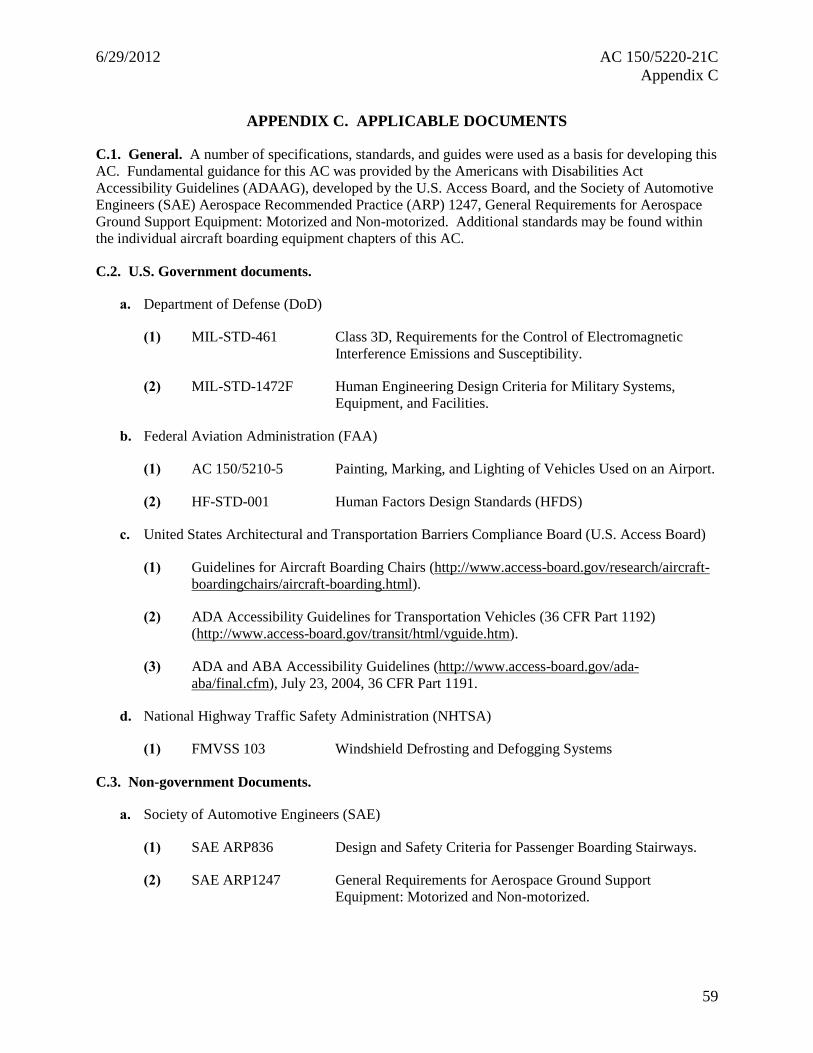
6/29/2012 AC 150/5220-21C
Appendix C
59
APPENDIX C. APPLICABLE DOCUMENTS
C.1. General. A number of specifications, standards, and guides were used as a basis for developing this
AC. Fundamental guidance for this AC was provided by the Americans with Disabilities Act
Accessibility Guidelines (ADAAG), developed by the U.S. Access Board, and the Society of Automotive
Engineers (SAE) Aerospace Recommended Practice (ARP) 1247, General Requirements for Aerospace
Ground Support Equipment: Motorized and Non-motorized. Additional standards may be found within
the individual aircraft boarding equipment chapters of this AC.
C.2. U.S. Government documents.
a. Department of Defense (DoD)
(1) MIL-STD-461 Class 3D, Requirements for the Control of Electromagnetic
Interference Emissions and Susceptibility.
(2) MIL-STD-1472F Human Engineering Design Criteria for Military Systems,
Equipment, and Facilities.
b. Federal Aviation Administration (FAA)
(1) AC 150/5210-5 Painting, Marking, and Lighting of Vehicles Used on an Airport.
(2) HF-STD-001 Human Factors Design Standards (HFDS)
c. United States Architectural and Transportation Barriers Compliance Board (U.S. Access Board)
(1) Guidelines for Aircraft Boarding Chairs (http://www.access-board.gov/research/aircraft-
boardingchairs/aircraft-boarding.html).
(2) ADA Accessibility Guidelines for Transportation Vehicles (36 CFR Part 1192)
(http://www.access-board.gov/transit/html/vguide.htm).
(3) ADA and ABA Accessibility Guidelines (http://www.access-board.gov/ada-
aba/final.cfm), July 23, 2004, 36 CFR Part 1191.
d. National Highway Traffic Safety Administration (NHTSA)
(1) FMVSS 103 Windshield Defrosting and Defogging Systems
C.3. Non-government Documents.
a. Society of Automotive Engineers (SAE)
(1) SAE ARP836 Design and Safety Criteria for Passenger Boarding Stairways.
(2) SAE ARP1247 General Requirements for Aerospace Ground Support
Equipment: Motorized and Non-motorized.

AC 150/5220-21C 6/29/2012
Appendix C
60
(3) SAE ARP5140 Design Criteria for Lifts Used to Board Passengers with Mobility
Impairments onto Aircraft with Doorsill Heights of 144 inches or
Less.
(4) SAE ARP5141 Chassis Mounted Lifts Used to Board Airline Passengers With
Mobility Impairments.
(5) SAE J1503 Performance Test for Air-Conditioned, Heated, and Ventilated
Off-Road Self-Propelled Work Machines.
b. National Fire Protection Association (NFPA)
(1) NFPA 70 National Electric Code (NEC)
(2) NFPA 415 Standard on Airport Terminal Buildings, Fueling Ramp
Drainage, and Loading Walkways
c. Air Transport Association (ATA)
(1) Spec 101 Ground Equipment Technical Data
C.4. Order of precedence. In the event of a conflict between the text of this document and the
references cited herein, the text of this document takes precedence. Nothing in this document, however,
supersedes applicable laws and regulations unless a specific exemption has been obtained.
C.5. Document Availability. Copies of the referenced documents may be obtained by contacting the
following:
a. ANSI – American National Standards Institute, 11 West 42nd
Street, New York, NY 10036.
b. DOD – Military specifications, standards, and handbooks are available from: Standardization
Documents Order desk, Bldg 4D, 700 Robbins Avenue, Philadelphia, PA 19111-5094.
c. FAA – The public may obtain electronic copies of this AC by visiting the FAA home page and
navigating to the Advisory Circular database (www.faa.gov).
d. U.S. Access Board – Architectural and Transportation Barriers Compliance Board, 1331 F Street,
N.W., Suite 100, Washington, D.C. 20004-1111. www.access-board.gov
e. SAE – Society of Automotive Engineers, 400 Commonwealth Drive, Warrendale, PA 15096-
0001
f. ISO – International Organization for Standardization, 1, ch. de la Voie-Creuse CP 56, CH-1211
Geneva 20, Switzerland. www.iso.org
g. NFPA – National Fire Protection Association, 1 Batterymarch Park, Quincy, Massachusetts,
02169-7471. www.nfpa.org
h. ATA – Air Transport Association (ATA) Publications Department, 1301 Pennsylvania Ave.,
NW, Suite 1100, Washington, DC 20004. [email protected]

6/29/2012 AC 150/5220-21C
Appendix C
61
i. NHTSA – NHTSA HQ, 1200 New Jersey Avenue, SE, West Building Washington, DC 20590.
www.nhtsa. gov

AC 150/5220-21C 6/29/2012
Appendix C
62
This page intentionally left blank.
6/29/2012 AC 150/5220-21C
Appendix D
63
APPENDIX D. ANNOTATED BIBLIOGRAPHY
D.1. Advisory Circulars
AC 150/5210-5D, Painting, Marking, and Lighting of Vehicles Used on an Airport, dated April 1, 2010.
FAA recommends these guidelines and standards for vehicles operating in the airport. Vehicle is defined
as all conveyances, except aircraft, used on the ground to transport persons, cargo, equipment or those
required to perform maintenance, construction, service, and security duties. Use of these guidelines is
mandatory for vehicles funded under Federal grant assistance programs.
D.2. Guidance
SAE ARP1247, General Requirements for Aerospace Ground Support Equipment, Motorized and Non-
Motorized. This document is a recommended practice outlining the general design requirements for
ground support equipment used in civil air transportation industry. It is intended to assist the airlines in
standardizing the requirements for various ground equipment. Topics addressed include safety of person
operating equipment, safety of person using equipment, safety of the equipment itself, maintenance of the
equipment, repairs, and testing.
United States Architectural and Transportation Barriers Compliance Board (Access Board) Guidelines for
Aircraft Boarding Chairs. This document is a technical paper intended to improve the design and use of
aircraft boarding chairs as a result of safety problems and complaints regarding the use of boarding chairs.
The scope of the guidelines is broad enough to apply to the various types of boarding chairs and is in no
way intended to restrict design freedom. The needs of both the person with a disability using the
boarding chair and the airline employees assisting the person with a disability, thus the physical
characteristics of both types of users, are described in the paper. The technical design sections outline the
seat size and capacity, adjustable parts, removable parts, safety belts, wheels, backrest, arms, cushioning,
and footrests. Inspection of the devices and training on use of the devices is also addressed.
United Stated Department of Transportation’s Technical Assistance Manual What Airline Employees,
Airline Contractors, and Airline Travelers with Disabilities Need to Know About Access to Air Travel for
Persons with Disabilities: A Guide to the Air Carrier Access Act (ACAA) and its implementing
regulations, 14 CFR Part 382, provides guidance to employees/contractors of air carriers on the services,
facilities and accommodations required by the ACAA to assist passengers with disabilities. This Manual
addresses assisting air travelers with disabilities plan their trip, throughout the airport, onto the aircraft,
during flight, deboarding, stowage of personal equipment on the aircraft, and how to file a complaint if
necessary.

AC 150/5220-21C 6/29/2012
Appendix D
64
This page intentionally left blank.