abstract - ircobi · processing of numerical results based on reconstruction of well documented...
TRANSCRIPT

Abstract The coupling of new medical imaging data, fractional anisotropy and axonal fiber orientation from
Diffusion Tensor Imaging (DTI) of 12 healthy patients called the DTI atlas with the Strasbourg University Finite
Element Head Model has been done to improve the brain constitutive material law with more efficient
improved heterogeneous anisotropic visco‐hyperelastic material law. The robustness was investigated by
validating the brain behavior in terms of local brain motion data from Hardy’s PMHS experiments. A reasonable
agreement is observed between experimental and simulation data for the complex three‐dimensional brain
motion patterns. This study provides a realistic and feasible method for DTI data incorporation into the brain FE
model for the next generation of human head FE modelling.
Keywords Brain anisotropy, DTI, finite element head model, local brain motion
I. INTRODUCTION
Among all the injuries sustained by vulnerable road users, vehicle occupants in road accidents and in sports,
traumatic brain injury (TBI) accounts for most of the deaths and permanent disabilities. An estimated 1.7 million
people in the US experience TBI annually [1] and almost 2% of the US population is living with TBI related
disabilities [2]. In most severe TBI cases, diffuse axonal injury (DAI) is the most common pathology in which
dynamic tensile elongation of axonal fibers leads to fiber rupture and axonal degeneration [3‐4]. Addressing
axon elongation within the brain during head impact can allow a better understanding of the DAI mechanism.
In anticipation of exponential growth in TBI, computational head modeling has proved to be an efficient and
very promising tool for both the establishment of head injury criteria and studies on head injury mitigation.
Finite element head models (FEHM) are a well known way to describe the intracerebral mechanical behaviour
during a head impact [5‐6] and hence to develop diffuse axonal injury (DAI) prediction tools. Previous brain
models reported in the literature are usually considered as homogeneous and isotropic for simplification
reasons [5‐10]. Moreover, brain mechanical properties are typically derived from in vitro experiments
conducted on post mortem brain samples. These hypotheses were acceptable from a mechanical point of view
as long as no advanced in vivo data were available.
Nowadays novel imaging techniques (MRE, DTI) give new insight into brain mechanics than the classical FE
computed metrics which may not be adequate to understand the mechanism of axonal impairment and the
varying vulnerability of the neurological cells within the brain. Diffuse Tensor Imaging (DTI) is a new MRI
technique based on water diffusion in soft tissue and Magnetic Resonance Imaging (MRI). This method thus
provides information on the orientation of axons and fractional anisotropy by tracking Brownian motion of
water molecules in all three dimensions within the brain in a non‐invasive manner. Chatelin et al. [11]
incorporated the DTI data (both fractional anisotropy and fiber orientation) for the first time into the post
processing of numerical results based on reconstruction of well documented motorcycle accident cases and was
able to predict the injury locations in accordance with the injury sustained by victims. Wright et al. [12]
conducted two‐dimensional plane strain FE analysis of the brain for different regions of interest by
implementing anisotropy into the constitutive hyperelastic material model for white matter. The result of this
study showed the significant influence of inclusion of anisotropy in the FEHM for predicting DAI. Colgan et al.
[13] also incorporated anisotropic orientations of axonal fibers into a non‐linear elastic material model for a FE
brain to predict the mechanical response and effect of anisotropy in case of high rotational TBI. Kraft et al. [14] performed frontal impact FEHM simulations by including DTI data into a hyperelastic brain model and predicted
D. Sahoo is a Doctoral student at the Institute for Fluid and Solid Mechanics, University of Strasbourg, 2 rue Boussingault, Strasbourg, FRANCE. C. Deck is a PhD Researcher in Biomechanics and R. Willinger is a Professor in Biomechanics at the University of Strasbourg (tel: 00 333 68 85 29 23, fax: 00 33 3 68 85 29 36, email: [email protected]).
Debasis Sahoo, CarolineDeck, RémyWillinger
Medical Imaging Data Implementation into Human FE Head Modelling and Validation
IRC-13-66 IRCOBI Conference 2013
- 563 -

that the temporal and occipital regions undergo the most axonal strain. However, exclusion of visco‐elasticity
was a limitation to this study. All these studies point to the importance of the implementation of anisotropy in
the FE brain model. The present paper proposes to implement both DTI‐based brain heterogeneity and
anisotropy into the FEHM and to validate the model.
In order to enhance the biofidelity and accuracy of the FEHM for more realistic injury assessments, the
model should be validated under impact conditions by comparing and correlating the simulation results against
experimental data. Most of the existing models have been validated against the pressure data of Nahum et al.
[15] and Trosseille et al. [16]. However, it is not acceptable to validate FE models for pressure only and then use
them for injury prediction [17]. Experimental study of brain strain due to brain deformation and relative motion
between the brain and skull during different impact scenarios provides a unique way to validate the FEHM.
Motion of the brain relative to the skull occurs during normal activity. However, if the head undergoes an
intolerable level of energy by high acceleration during impact, the induced large deformation of neuronal and
axonal tissue can lead to severe TBI and long‐term disabilities [18]. Very few studies are available that measure
the relative motion between brain and skull by conducting low energy impact tests to post mortem human
subjects (PMHS) [19‐22]. Although, the PMHSs do not predict the DAI, the mechanical response can be
determined. Experimental data extraction pertaining to brain displacement, strain and strain rate, skull
displacement, acceleration and velocity for FE model validation leads to improvement in the head injury
prediction [6].
In the present study the incorporation of fractional anisotropy and axonal fiber orientation from DTI of 12
healthy patients called the DTI atlas with an existing head FEM has been proposed in order to update existing
brain mechanical constitutive law. The outcome of this step is an advanced heterogeneous and anisotropic brain
FE model which is able to compute local axonal elongation following impact. The brain behavior has been validated in terms of local motion (relative motion between brain and skull) of brain data provided by Hardy et
al. [20‐21]. This study provides a realistic method to understand the importance of axonal strain as a novel brain
injury metric.
II. MATERIALS AND METHODS
Presentation of Finite Element Head Model
In the present study the Strasbourg University Finite Element Head Model (SUFEHM), which is a 50th
percentile FE model of the adult human head, developed under Radioss software [7] and transferred to LS‐
DYNA [23‐24], was used as a base model for further improvement. The main anatomical features include the
scalp, the brain, the brainstem and the cerebrospinal fluid (CSF) represented by brick elements and the skull, the
face and two membranes (the falx and the tentorium) modeled with shell elements as shown in Table 1.
The total mass of the FE head model is 4.7 kg which is equivalent to the mass of a 50th percentile adult
human head and composed of 13208 elements with a continuous mesh including 5320 elements representing
the brain. Isotropic, homogeneous and elastic mechanical constitutive material was applied to each of the
SUFEHM parts except for the brain. The mechanical properties of all parts of the SUFEHM are reported in Table
1. The mechanical parameters of the material which models the subarachnoid space have been derived from
experimental and numerical head modal analysis as reported in Willinger et al. [25]. The visco‐elastic material
parameters for the brain model were identified from the experimental in vitro data on human brain tissue
proposed by Shuck and Advani [26] as well as recent in vivo based values from Magnetic Resonance
Elastography (MRE) published by Kruse et al. [27], with the following values: G0 = 49 × 103 Pa, G∞ = 1.62 × 10
4 Pa,
β = 145 s−1. Validation of the SUFEHM against intracranial pressure data from Nahum et al. [15] and Trosseille et
al. [16] was proposed by Kang et al. [7], Willinger et al. [28] and Deck et al. [29] under the Radioss code and by
Deck and Willinger [23‐24] under the LS‐DYNA code. This FEHM is used as a base model for the improvement of
brain by incorporating DTI data and anisotropic visco‐hyperelastic law.
TABLE 1 DETAILED SUFEHM MODEL WITH MECHANICAL PROPERTIES [7]‐[23‐24]
IRC-13-66 IRCOBI Conference 2013
- 564 -

Parts
Face
Scalp
Brain
Brain stem
CSF
Falx and Tentorium
Density [kg/m3]
2500 1000 1040 1040 1040 1140
Young’s modulus [MPa]
5000 16.7 Viscoelastic
0.012 31.5
Poisson’s ratio
0.23 0.42 0.49 0.45
Element type Shell Brick Brick Brick Brick Shell Shell
thickness [mm]
1 ‐ ‐ ‐ ‐ Falx=1
Tentorium= 2
DTI Data Collection
A DTI Atlas was developed, based on the data acquisition from diffusion tensor images of 12 healthy
volunteers on a 1.5‐T scanner (Magnetom Vision; Siemens Medical Systems, Erlangen, Germany) using a 60‐
gradient sequence with two b0 images for 12 controls, with a resolution of 1.7 by 1.7 by 3.5 mm for an image
size of 182 by 182 by 218 mm. At present emphasis is given to two parameters obtained from DTI data. The
parameters are fractional anisotropy (FA) and the anisotropy vector l
. FA is the scalar measurement of
diffusion anisotropy and the norm of lis FA [30]. Diffusion tensors are estimated with a standard least square
algorithm [30] and FA is computed for each patient. Each component of diffusion tensor is registered in the
brain mapping DTI template space using sinus cardinal interpolation strategy [31‐33] to construct the DTI Atlas.
The orientation and shape information of tensor imaging are preserved using the preservation of principal
direction reorientation strategy [34]. The Euclidean mean values for diffusion tensor were calculated in all
directions maintaining voxel size of 1 by 1 by 1 mm and picture size of 181 by 181 by 217 mm [11].
The FA is obtained from the eigen values λ1, λ2 and λ3 of the diffusion tensor as expressed in Eq. 1 [30]. A FA
value of zero means the corresponding voxel is perfectly isotropic and there is no densely packed axon bundle
oriented in one principal axis to contribute to the voxel stiffness. A FA value of 1 corresponds to a totally
anisotropic voxel, with all the axons (axon bundle) included in the voxel oriented along that direction. The
anisotropy vector indicating the main axon‐bundle orientation for the voxel volume corresponds to the eigen
vector associated with the diffusion tensor maximal eigen value.
2 2 2 2 2 21 2 3 1 2 33 2FA
Where 1 2 3 3 (1)
The DTI template for FA and axonal fiber orientation obtained from the above methodology is shown in Fig 1
and Fig 2.
IRC-13-66 IRCOBI Conference 2013
- 565 -

Fig. 1. DTI template for fractional anisotropy. FA value
of zero corresponds to isotropic voxels and one
corresponds to totally anisotropic voxels
Fig. 2. DTI template for anisotropy vector (or fiber
orientation). (Red: transverse direction; Green:
antero‐posterior direction; Blue: vertical direction)
Integration of DTI Data into FE Brain Model
The correspondence between DTI data gathered from the DTI Atlas and the brain FEM involves a fitting
between imaging and numerical external geometries. This was performed using rigid transformations, i.e. only
rotation and translation, with a linear scaling of all the nodes from the SUFEHM. The finite element outlines
fitted to the DTI mask were based on the DTI Atlas (twelve patients) as shown in Fig 3. The correspondence
between DTI voxels and the FEM was performed using the Matlab 7.4 software (The Mathworks, Inc., Natick,
MA, USA).
Fig. 3. Rigid transformation application to ensure correspondence between mask of in
vivo diffusion data (in red) and brain FEM (in blue), with associated frames.
The voxel selection for each element encountered the discrepancy in size of voxel (regular pan parallel
meshing of 1mm by 1mm by 1 mm) and element size of SUFEHM which have different local orientation and size
range of 1.14 to 7.73 mm. To resolve this difference, the voxels were included into the smallest parallelepiped
lined with regular DTI meshing and the finite element selected for each element was incorporated as shown in
Fig 4. For each finite element two parameters were investigated for each selected DTI voxel; one is FA obtained
by Eq. 1 and the other one is anisotropy vector l. Considering the mean values of all selected voxels the
IRC-13-66 IRCOBI Conference 2013
- 566 -
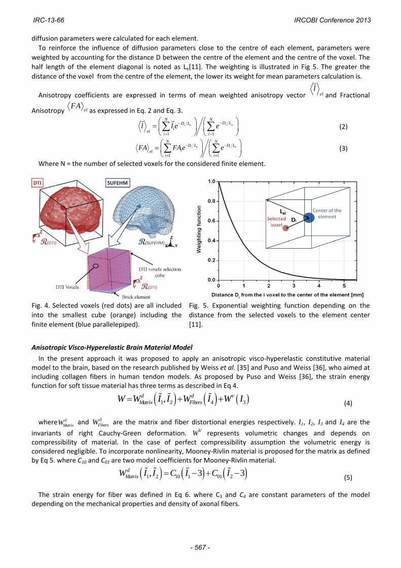
diffusion parameters were calculated for each element.
To reinforce the influence of diffusion parameters close to the centre of each element, parameters were
weighted by accounting for the distance D between the centre of the element and the centre of the voxel. The
half length of the element diagonal is noted as Le[11]. The weighting is illustrated in Fig 5. The greater the
distance of the voxel from the centre of the element, the lower its weight for mean parameters calculation is.
Anisotropy coefficients are expressed in terms of mean weighted anisotropy vector ell
and Fractional
Anisotropy elFA
as expressed in Eq. 2 and Eq. 3.
1 1
ii e e
N ND LD L
iel
i i
l l e e
(2)
1 1
i e i e
N ND L D L
ieli i
FA FAe e
(3)
Where N = the number of selected voxels for the considered finite element.
Fig. 4. Selected voxels (red dots) are all included
into the smallest cube (orange) including the
finite element (blue parallelepiped).
Fig. 5. Exponential weighting function depending on the
distance from the selected voxels to the element center
[11].
Anisotropic Visco‐Hyperelastic Brain Material Model
In the present approach it was proposed to apply an anisotropic visco‐hyperelastic constitutive material model to the brain, based on the research published by Weiss et al. [35] and Puso and Weiss [36], who aimed at including collagen fibers in human tendon models. As proposed by Puso and Weiss [36], the strain energy function for soft tissue material has three terms as described in Eq 4.
1 2 4 3,d dMatrix FibersW W I I W I W I (4)
where dMatrixW and d
FibersW are the matrix and fiber distortional energies respectively. I1, I2, I3 and I4 are the
invariants of right Cauchy‐Green deformation. WV represents volumetric changes and depends on compressibility of material. In the case of perfect compressibility assumption the volumetric energy is considered negligible. To incorporate nonlinearity, Mooney‐Rivlin material is proposed for the matrix as defined by Eq 5. where C10 and C01 are two model coefficients for Mooney‐Rivlin material.
1 2 10 1 01 2, 3 3dMatrixW I I C I C I (5)
The strain energy for fiber was defined in Eq 6. where C3 and C4 are constant parameters of the model depending on the mechanical properties and density of axonal fibers.
IRC-13-66 IRCOBI Conference 2013
- 567 -

4* 1
3
0 0 1
1 1
dFibers
FA C
W
C e
(6)
Viscosity plays a significant role in the response of brain matter to quasi‐static loading as well as impact scenarios due to high strain rate sensitivity [37]. The viscoelastic behavior is described by Eq 7 by considering the time‐dependent second Piola‐Kirchhoff stress S(C,t), as proposed by Fung [38].
, ,e vS C t S C S C t (7)
eS C is the equilibrium stress representing the long term elastic material behavior. Rate effects are taken
into account through linear viscoelasticity via a convolution integral representation, as indicated in Eq 8.
0
, 2 ( )( )
tv WS C t G t s ds
C s
(8)
( )G t s is the reduced relaxation function that has been combined with n‐order Prony series, as expressed in Eq 9.
1
( ) i
nt T
ii
G t S e
(9)
Si and Ti are shearing relaxation moduli and decay constants respectively, which characterize strain rate sensibility of the model. The parameter identification for the anisotropic visco‐hyperelastic law is based on various in vivo and in vitro
experimental data reported in the literature [39]. In the present study all the parameters were identified by Chatelin et al.[40] and reported in Table 2 . The Mooney‐Rivlin parameters C10 and C01 were identified by downhill simplex method from in vivo MRE test data performed by Kruse et al. [27] and also taking into account the stiffening of brain tissue between 50 and 60% stretch in compression at low as well as at high strain rate values [37, 41‐42]. The viscosity parameters Si and Ti were identified from experimental relaxation data in shearing dynamic mechanical analysis by Shuck and Advani [26]. The resulting relaxation modulus versus time curve is scaled to 13.6 kPa [27] to ensure continuity between the viscoelastic (linear) and hyperelastic (nonlinear) models. In the current study, the brain fibers are taken as hyperelastic material due to lack of experimental data for the viscous nature of the brain fiber. This anisotropic visco‐hyperelastic material model is validated against experimental tests conducted by Estes and McElhaney [43] and the parameter identification and validation were published in Chatelin et al. [40]. The parameters were implemented in *MAT_092_SOFT_TISSUE_VISCO material model under LS‐DYNA® platform to conduct impact simulations. Anisotropy vector l0 is defined for each element in a local frame and defined for axis A (coordinates Ax, Ay and Az in FEM global frame) and B (coordinates Bx, By and Bz in FEM global frame).
TABLE. 2 PARAMETERS VALUES FOR *MAT_092_SOFT_TISSUE_VISCO MATERIAL
IMPLEMENTED FOR BRAIN TISSUE SAMPLE UNDER LS‐DYNA® SOFTWARE [40]
LS‐DYNA Parameters Constitutive Parameters Units Value ρ ρ kgxm‐3 1040 K K MPa 1125 C1 C10 kPa ‐1.034 C2 C01 kPa 7.809 C3 C3 kPa 13.64 C4 C4 4.6
S1 and S2 S1 and S2 kPa 4.5 and 9.11 T1 and T2 T1 and T2 s‐1 1x10⁹ and 6.90
Experimental Brain Strain Data for FE Brain Validation
The experimental data published by Hardy [20‐21] were taken into account in which the principal focus of
experiments was the measurement of relative brain motion with respect to the skull and between different
regions of the brain. The local brain motion was measured by tracking neutral‐density targets (NDTs) by using a
IRC-13-66 IRCOBI Conference 2013
- 568 -

high‐speed biplanar x‐ray system during different impact conditions. These targets were designed to occupy a
minimal volume (density was 1.05 gm/ml or below) and to move with the brain without lacerating the brain
during the impact. The NDTs are implanted in two vertical columns located in the occipitoparietal and
temporoparietal regions in Hardy et al. [20] and in a cluster further from the centre of gravity (CG) of the head
(than former) in Hardy et al. [21]. From all the experiments conducted by Hardy, 11 tests are taken into account
to analyze the brain behavior. In order to reproduce numerically the experimental impact motion of the head
and to calculate the relative displacement of the brain, the SUFEHM with new constitutive law for the brain is
used under LS‐DYNA®. The anisotropic brain SUFEHM model is illustrated in Fig 6. Those nodes of the FEHM
situated at the nearest location to the location of NDTs are taken into account to investigate the brain response.
The skull was modeled as rigid in the present study. The head kinematics (all six degrees of freedom) coming
from experimental data (Fig 7) were applied to the local co‐ordinate system attached to the CG of the head
model. The simulations for 11 tests were conducted and the relative displacement data of selected nodes were
compared with experimental NDT displacement.
Fig. 6. Heterogeneous and anisotropic brain model Fig. 7. Experimental data used as input during simulation
[20]
III. RESULTS
Integration of DTI Data into FE Brain Model
From the coupling of brain meshing from SUFEHM, DTI data (Fractional anisotropy and anisotropy vector)
from the DTI Atlas and the new anisotropic visco‐hyperelastic constitutive law, an advanced heterogeneous and
anisotropic SUFEHM brain model was obtained, as illustrated in Fig 8 from three different views (sagittal,
coronal and frontal). Anisotropy vectors are shown in red for transverse direction, green for antero‐posterior
direction and blue for vertical direction. For each of the 5320 SUFEHM brain elements, the same material law
with different anisotropy vector and FA parameters was implemented. The FA and anisotropy vector for each
element were calculated using Eqs 2 and 3 by taking into account the exponential weighting function applied to
the selected voxels. Finally, the FAs were incorporated in Eq 6 and then implemented to each element of the
SUFEHM brain model by using *MAT_092_ SOFT_TISSUE_VISCO material model under LS‐DYNA® platform. This
protocol facilitated a proposed anisotropic visco‐hyperelastic brain model.
IRC-13-66 IRCOBI Conference 2013
- 569 -

Saggital view
Coronal View Frontal view
Fig. 8. Illustration of the coupling between anisotropy information and brain FEM meshing. Anisotropy vectors
are shown (Red: transverse direction; Green: antero‐posterior direction; Blue: vertical direction).
Anisotropic Brain Model Validation against Experimental Brain Strain Data
A total of 11 simulations from Hardy’s experiments were reproduced with the anisotropic brain model and
from which two simulation results with id C755‐T2 [20] and C288‐T1 [21] are represented in this study. The
results of simulation for the relative displacement of five NDT locations in the X and Z direction for the occipital
impact test C755‐T2 and its comparison with experimental data are illustrated in Fig 9 and Fig 10 respectively.
The motion pattern of the NDTs is typically characterized by a maxima and minima between 20‐40 ms and after
that the motion pattern decays reaching a value of zero.
The displacement time histories for NDTs located at the temporoparietal and occipitoparietal regions are
shown by the plots in the top and bottom part of both Fig 9 and Fig 10 respectively.
Fig. 9. Experimental and numerical displacement time histories comparison for NDT location in X direction for
test C755‐T2.
All the plots were quantified by calculating average discrepancy in maxima and minima of plots between the
simulations and experimental data. The minima and maxima for motion of NDTs in the X direction were
underestimated by an average of 18 percent and an average of 11.5 percent in the Z direction considering the
results up to 40ms. Hence, the average difference in the prediction of the brain relative motion at NDT location
is 14.75 percent along both directions. In both X and Z direction motion prediction, the average discrepancy in
minima prediction is less than the maxima prediction. The root mean square error between the experiment and
simulation result was calculated for all the NDTs and the average root mean square error is 0.81 for test C755‐
T2.
IRC-13-66 IRCOBI Conference 2013
- 570 -

Fig. 10. Experimental and numerical displacement time histories comparison for NDT location in Z direction for
test C755‐T2.
For the test with test id C288‐T1 [21], the simulation reproduced an aligned occipital impact. The comparison
of experimental and numerical results for brain relative motion is shown in Fig 11. These plots include motion
data for only two NDT locations due to lack of availability of data in the literature. However, a complete
comparison of data is shown in Fig 12.
Fig 11 ‐ Experimental and numerical displacement time histories comparison for NDT location in X and Z direction for test C288‐T1.
The maxima of NDT 4 and 11 were overestimated by 6 percent, but the minimum of NDT 4 was under‐
estimated by 2.5 percent in motion along the X direction. For motion along the Z direction, the average
discrepancy in minima and maxima was 4 percent considering both NDTs. The root mean square error between
the experiment and simulation results was calculated for all the NDTs and the average root mean square error
was 0.42 for test C288‐T1. The left side of Fig 12 represents the experimental data and the right side of Fig 12
represents the simulation data. The arrows point to the direction of impact in both cases. Each trajectory is
numbered according to the NDTs implanted in the PMHS head test. Similar local brain motion in a “butterfly”
pattern is also observed in this case. The motion pattern for impact in the median, coronal and horizontal planes
shows similarities.
IRC-13-66 IRCOBI Conference 2013
- 571 -

Fig 12 ‐ Brain motion pattern for two NDT clusters for an aligned occipital impact test C288‐T1. (Left:
experimental results and right: numerical results)
IV. DISCUSSION
The objective of this study was to incorporate medical imaging (DTI) data from the DTI Atlas into an existing
human FE head model and was accomplished by enhancing the existing brain model with anisotropic
heterogeneous visco‐hyperelastic brain constitutive law. The brain behavior was validated in terms of local
motion of the brain relative to the skull, and a reasonable agreement between the experimental and numerical
simulation results was obtained for Hardy’s experiments [20‐21]. As reported in the literature, very few authors
have validated the FE head model against Hardy’s [20] experiments [8‐10] and there is no depiction of validation
against Hardy et al. [21]. In the present study, it was found to be realistic to reproduce both magnitude and
overall shape of complex three‐dimensional localized brain tissue motions for impacts in multiple directions
(frontal, occipital, lateral) and different planes (sagittal, coronal). The current results are better predicted than
[9] by taking into account the average discrepancy in maxima and minima, which is 45% in Kleiven et al. [9] and
less in the current study. The average discrepancy (percentage of underestimation of peak) in predicting the
peak results may be due to the fact that the PMHS brain material properties are less stiff [39] than the in vivo
brain material properties as reported by Chatelin et al. [40]. In addition, it is observed that for the same amount
of energy input to the impact experiments, there is less amplitude obtained for the motion pattern of NDTs in
Hardy [21] than Hardy [20], which indicates the complexity and difficulties in conducting good experiments.
The limitations of this study include the selection of the nearest node to the location of NDTs to get the brain
motion in simulations. To address this issue, the adjacent nodes to the node chosen to represent the NDT were
tracked and the relative displacement time histories were compared to the representative node relative
displacement time history as shown for one NDT (a1x located at temporoparietal region) for the test C755‐T2 in
Fig 13. This comparison was performed for all the target NDTs and the corridor for the adjacent nodes data lies
below +/‐5 %, which plays a minimal role in affecting the average discrepancy calculation.
Also difficulties arose with voxel selection for the finite element. When there is no or not enough DTI voxels
of the brain considered to be significant, this creates uncertainty concerning the rigid transformation in scaling
the FE model on DTI brain shape data. However, it was found that only 6 elements (0.11 % of the elements)
selected individually less than 100 DTI voxels. These were located close to the membranes and were relatively
thin elements. This aspect contributed to validate the morphological rigid adaptation between DTI and FEM
geometry without taking non‐rigid transformation into account. On the other hand, the high numbers of
selected voxels per element led to the necessity of weighting diffusion parameters of the selected voxels as a
function of their distance from the centre of the element. This was done in order to decrease the influence of
diffusion parameters related to the voxels close to the edges of the element. Since DAI appears in the most
anisotropic parts of the brain, it would not affect the efficiency of the method for DAI prediction. Another
consequence of applying such a voxel mean diffusion parameters calculation is the smoothing of diffusion
parameters values between elements [11]. The data resolutions achievable with current state of the art DTI are
still insufficient to access meshing at the axon size for the whole brain. Nevertheless, only the mean diffusion
IRC-13-66 IRCOBI Conference 2013
- 572 -

parameters seem to be satisfactory in obtaining a realistic orientation and an anatomical anisotropy degree for
each of the finite elements. Even if an original methodology has been set in the context of the present study,
other head FE models would gain anisotropy description by refined meshing.
In this study, the constitutive material law incorporated into the brain FE model is based on the research as
reported in the literature [35‐36]. This model also assumed that the brain fibers (axon bundles) have the same
kind of influence on brain tissue as collagen fibers have on mechanical behavior of ligaments. To investigate the
effect of the DTI parameters (FA and axonal fiber orientation), simulations were conducted with a brain FE
model by implementing zero for FA value in Eq.6. The comparison of results between brain FE model with and
without FA values are shown in Fig 14 for one NDT (a1 located at the temporoparietal region) for the C755‐T2
test. The direction of fiber orientation was mostly along the Y direction as implemented from the DTI Atlas.
When there is FA, with the influence of the fiber, stiffening the motion along Y is restricted as shown in
comparison to other directions of motion. However, when there is no influence of fiber, due to the resultant
force along Y there is more displacement (a factor of 2 approximately) along the Y direction compared to the
other two directions. In the latter case the displacement increment along Y and the decrement along other
directions are proportional which is in accordance with the property of an incompressible material. It is clear
from Fig 14 that the inclusion of DTI parameters (anisotropy) in the brain FE model has significant influence in
predicting the local motion of brain tissue and also increase the confidence in this methodology and new brain
FE model.
Fig. 13. Relative displacement time history
comparison between representative node and
adjacent nodes.
Fig. 14. Comparison of displacement time history for
simulation with FA and without FA for test C755‐T2 for NDT
a1 in X, Y and Z direction.(No experimental data available for
Y motion)
V. CONCLUSIONS
New medical imaging data, fractional anisotropy and axonal orientation data from 12 healthy patients (the DTI Atlas) are incorporated into an existing brain model. The robustness of the methodology by adding new anisotropic visco‐hyperelastic material law for the brain is illustrated by validating the brain behavior in terms of local brain motion with PMHS experimental data. The complex 3D brain motion patterns are reasonably reproduced for comparison with experiments and the average discrepancy (percentage of underestimation of peak) in predicting the peak results shows that the post mortem brain material properties are less stiff than the in vivo brain material considered for the brain model. The benefits of implementation of new non‐invasive in vivo medical data for head injury prediction are underscored. The results of the simulation strongly support the idea of structural anisotropy having a great influence on brain response and the feasibility of implementing DTI data in a realistic way.
VI. ACKNOWLEDGEMENT
The authors would like to acknowledge the MAIF Foundation for their support for this research work.
IRC-13-66 IRCOBI Conference 2013
- 573 -

VII. REFERENCES
[1] Faul M, Xu L, Wald MM, Coronado VG, Traumatic brain injury in the United States: emergency department visits, hospitalizations and deaths 2002–2006, Centers for Disease Control and Prevention, National Center for Injury Prevention and Control, 2010,Atlanta, GA.
[2] Langlois JA, Rutland‐Brown W, Wald MM, The epidemiology and impact of traumatic brain injury: a brief overview, Journal of Head Trauma Rehabilitation, 2006, 21(5):375‐378.
[3] Arfanakis K, Haughton VM, Carew JD, Rogers BP, Dempsey RJ, Meyer ME, Diffusion tensor MR imaging in diffuse axonal injury, American Journal of Neuroradiology, 2002, 23:794–802.
[4] Smith D H, & Meaney D F, Axonal damage in traumatic brain injury, The Neuroscientist, 2000, 6:483–495.
[5] Raul JS, Deck C, Willinger R, & Ludes B, Finite element models of the human head and their applications in forensic practice, International Journal of Legal Medicine, 2008, 122:359–366.
[6] Zhang L, Yang K, Dwarampudi R, Omori K, Li T, Chang K, Hardy W, Kahlil T, King A, Recent advances in brain injury research: a new human head model development and validation, Stapp Car Crash Journal, 2001, 45:369‐394.
[7] Kang HS, Willinger R, Diaw BM, Chinn B, Validation of a 3D human head model and replication of head impact in motorcycle accident by finite element modeling, Proceedings of the 41th Stapp Car Crash Conference, Society of Automotive Engineers, 1997, Lake Buena Vista, USA, pp. 329‐338.
[8] Al‐Bsharat A, Hardy W, Yang K, Kahlil T, Tashman S, King A, Brain/skull relative displacement magnitude due to blunt head impact: new experimental data and model, Proceedings of the 43th Stapp Car Crash Conference, Society of Automotive Engineers, 1999, pp. 321‐332.
[9] Kleiven S, Hardy WN, Correlation of an FE model of the human head with experiments on localized motion of the brain ‐ consequences for injury prediction, Stapp Car Crash Journal, 2002, 46:123–144.
[10] Horgan TJ, Gilchrist MD, Influence of FE model variability in predicting brain motion and intracranial pressure changes in head impact simulations, International Journal of Crashworthiness, 2004, 9(4):401‐418.
[11] Chatelin S, Deck C, Renard F, Kremer S, Heinrich C, Armspach JP, Willinger R, Computation of axonal elongation in head trauma finite element simulation, Journal of Mechanical Behavior of Biomedical Materials, 2011, 4(8):1905‐1919, ISSN 1751‐6161, 10.1016.
[12] Wright R, Ramesh K, An axonal strain injury criterion for traumatic brain injury, Biomechanics and Modeling in Mechanobiology, 2011, pp. 1‐16.
[13] Colgan NC, Gilchrist MD, Applying DTI white matter orientations to finite element head models to examine diffuse TBI under high rotational accelerations, Progress in Biophysics and Molecular Biology, 2010, 103(2‐3):304‐309.
[14] Kraft RH, Mckee PJ, Dagro AM, Grafton ST, Combining the finite element method with structural Connectome‐based analysis for modeling neurotrauma: Connectome Neurotrauma Mechanics, PLOS Computational Biology, 201230, 2, 102‐118.
[15] Nahum A, Smith R, Ward C, Intracranial pressure dynamics during head impact, Proceedings of the 21st Stapp Car Crash Conference, 1977, SAE Paper No. 770922.
[16] Trosseille X, Tarriere C, Lavaste F, Guillon F, Domont A, Development of a F.E.M. of the human head according to a specific test protocol, Proceedings of the 36th Stapp Car Crash Conference, 1992, SAE Paper No. 922527.
[17] Bradshaw DRS, Morfey CL, Pressure and shear response in brain injury models, Proceedings of the 17th International Technical Conference on the Enhanced Safety of Vehicles, 2001, Amsterdam, The Netherlands.
[18] Bain AC, Meaney DF, Tissue‐level thresholds for axonal damage in an experimental model of central nervous system white matter injury, Journal of Biomechanical Engineering, 2000, 16:615‐622.
[19] Hodgson VR, Gurdjian ES, Thomas LM, Experimental skull deformation and brain displacement demonstrated by flash X‐ray technique, Journal of Neurosurgery, 1966, 25:549–552.
[20] Hardy WN, Foster CD, Mason MJ, Yang KH, King AI, Tashman S, Investigation of head injury mechanisms using neutral density technology and high‐speed biplanar X‐ray, Stapp Car Crash Journal, 2001, 45:337‐368.
[21] Hardy WN, Mason MJ, Foster CD, Shah CS, Kopacz JM, Yang, KH, King AI, Bishop J, Bey M, Anderst W, Tashman S, A study of the response of the human cadaver head to impact, Stapp Car Crash Journal, 2007, 51:17‐80.
IRC-13-66 IRCOBI Conference 2013
- 574 -

[22] Zou H, Schmiedeler JP, Hardy WN, Separating brain motion into rigid body displacement and deformation under low‐severity impacts, Journal of Biomechanics, 2007, 40:1183–1191.
[23] Deck C, Willinger R, Improved head injury criteria based on head FE model, International Journal of Crashworthiness, 2008, 13(6):667–678.
[24] Deck C, Willinger R, Head injury prediction tool for predictive systems optimization, 7th European LS‐DYNA Conference, 2009, Salzburg, Austria.
[25] Willinger R, Taleb L, Pradoura P, Head biomechanics from the finite element model to the physical model, Proceedings of the IRCOBI Conference, 1995, Brunnen, pp. 245‐260.
[26] Shuck LZ, Advani SH, Rheological response of human brain tissue in shearing, ASME Journal of Biomechanical Engineering, 1972, pp. 905‐911.
[27] Kruse SA, Rose GH, Glaser KJ, Manduca A, Felmlee JP, Jack Jr. CR, Ehman R, Magnetic resonance elastography of the brain, NeuroImage , 2007,39(1):231‐237.
[28] Willinger R, Baumgartner D, Human head tolerance limits to specific injury mechanisms, International Journal of Crashworthiness, 2003, 8(6):605–617.
[29] Deck C, Nicolle S, Willinger R, Human head FE modelling: improvement of skull geometry and brain constitutive laws, Proceedings of the IRCOBI Conference, 2004, Graz, pp. 79‐ 92.
[30] Pierpaoli C and Basser PJ, Toward a quantitative assessment of diffusion anisotropy, Magnetic Resonance in Medicine, 1996, 36:893‐906.
[31] Mori S, Oishi K, Jiang H, Jiang L, Li X, Akhter K, Hua K, Faria AV, Mahmood A, Woods R, Toga AW, Pike GB, Neto PR, Evans A, Zhang J, Huang H, Miller MI, van Zijl P, Mazziotta J, Stereotaxic white matter atlas based on diffusion tensor imaging in an ICBM template, NeuroImage , 2008,40:570‐582.
[32] Horsfield MA, Mapping eddy current induced fields for the correction of diffusion‐weighted echo planar
images, Magnetic Resonance Imaging, 1999, 17:1335–1345.
[33] Nikou C, Heitz F, Nehlig A, Namer IJ, Armspach JP, A robust statistics‐based global energy function for the
alignment of serially acquired autoradiographic sections, Journal of Neuroscience Methods, 2003, 124:93‐
102.
[34] Alexander DC, Pierpaoli C, Basser PJ, Gee JC, Spatial transformation of diffusion tensor magnetic resonance images, IEEE Transactions on Medical Imaging, 2001, 20:1131‐1139.
[35] Weiss J, Maker B, Govindjee S, Finite element implementation of incompressible, transversely isotropic hyperelasticity, Computer Methods in Applied Mechanics and Engineering, 1996, 135:107–128.
[36] Puso MA, Weiss JA, Finite element implementation of anisotropic quasilinear viscoelasticity, ASME Journal of Biomechanical Engineering, 1998, 120(1):62–70.
[37] Prevost TP, Balakrishnan A, Suresh S, Socrate S, Biomechanics of brain tissue, Acta Biomateriala, 2010, 7:83‐95
[38] Fung YC, Biomechanics: mechanical properties of living tissues, Springer, NY, 1981. [39] Chatelin S, Constantinesco A, Willinger R, Fifty years of brain tissue mechanical testing: From in vitro to in
vivo investigations, Biorheology, 2010,47:255‐276, DOI: 10.3233/BIR‐2010‐0576 [40] Chatelin S, Deck C, Willinger R, An anisotropic viscous hyperelastic constitutive law for brain material finite
element modeling, Journal of Biorheology, 2012, 1‐12, ISSN 1867‐0466, DOI 10.1007/s12573‐012‐0055‐6. [41] Pervin F, Chen WW, Dynamic mechanical response of bovine gray matter and white matter brain tissues
under compression, Journal of Biomechanics, 2009, 42:731‐735. [42] Ning X, Zhu Q, Lanir Y, Margulies SS, A transversely isotropic viscoelastic constitutive equation for brainstem
undergoing finite deformation, Journal of Biomechanical Engineering ASME, 2006, 128, 6:925‐933. [43] Estes MS, McElhaney JH, Response of brain tissue to compressive loading, Proceedings of the 4th ASME
Biomechanics Conference, 1970, 70‐BHF‐13.
IRC-13-66 IRCOBI Conference 2013
- 575 -