abstract ~method of calculaxing the fluid …digitool.library.mcgill.ca/thesisfile46502.pdf ·...
TRANSCRIPT

ABSTRACT
~METHOD OF CALCULAXING THE FLUID
PROPERTIES RESULTING FROM SUPERSONIC
COMBUSTION IN A DUCT
B. Mackintosh Department of Mechanical Engineering
Master of Engineering
An analysis is provided for combustion in a supersonic
airstream confined to a duct of constant cross-section. The core
of the procedure is the establishment of an empirical parameter
known as the burning factor, introduced as a measure of the rate
at whichfuel is burned. A curve of burning factor versus duct
location shows the distribution of combustion. The flow is treated
as generalised one-dimensional flow with friction, are a change and
heat addition. The process of combustion is represented as a
combinat ion of heat and mass addition. Boundary layer effects and
heat loss from the du ct are considered.
The results indicate that the method is effective as
a means of predicting the static pressure distribution in the
duct, and it is amenable to relatively rapid computer solution.
The procedure may also be applied to convergent or divergent ducts.
CALCULATIONS FOR SUPERSONIC
COMBUSTION IN A DUCT
•
A METHOD OF CALCULATING THE FLUID
PROPERTIES RESULTING FROM SUPERSONIC
COMBUSTION IN A DUCT
by
B. MACKINTOSH
Submitted to the Department of Mechanical Engineering
of McGill University,
in partial fulfillment of the requirements for
the Degree of Master of Engineering.
McGill University Montreal, April 1969
té) B. Mackintosh 1969

•
•
ABSTRACT
An analysis is provided for combustion in a
supersonic airstream confined to a duct of constant
cross-section. The core of the procedure is th~ establishment
of an empirical parameter known as the burning factor,
introduced as a measure of the rate at which fuel is burned.
A curve of burning factor versus duct location shows the
distribution of combustion. The flow is treated as generalised
one-dimensional flow with friction, area change and heat addition.
The process of combustion is represented as a combinat ion of heat
and mass addition. Boundary layer effects and heat loss from the
duct are considered.
The results indicate that the method is effective as
a means of predicting the static pressure distribution in the
duct, and it is amenable to relatively rapid computer solution.
The procedure may also be applied to convergent or divergent
ducts •

•
•
ACKNOWLEDGEMENT
The author wishes to thank Professor J.M. Forde
for his interest and supervision of the work and in
particu1ar for permission to use certain data and ideas
originated by him (Ref. 15). The assistance of
Mr. R. Camarero in reading the ear1y draft of this thesis
and suggesting various improvements was most va1uab1e.
The author a1so wishes to thank Miss E. Bart1ey for doing
the typing.
The support of the Defence Research Board of
Canada i5 acknow1edged •
•
•
TABLE OF CONTENrS
ABSTRACT
ACKNOWLEDGEMENT
NOMENCLATURE
INrRODUCTION
GENERAL CONSIDERATIONS
THEORETICAL CONSIDERATIONS FOR ANALYSIS
EXPERlMENrAL INVESTIGATION
DISCUSSION OF RESULTS
CONCLUSION
REFERENCES
APPENDICES
1. Derivation of Equations
2. Certain Flow Properties
1. Air f10w through Mach 3.75 nozz1e
2. Stoichiometry of Kerosene
3. Heat re1eased by combustion of Ke:rosene
4. Performance of in je ct ors - Kerosene
5. Se1ected resu1ts for She11dyne
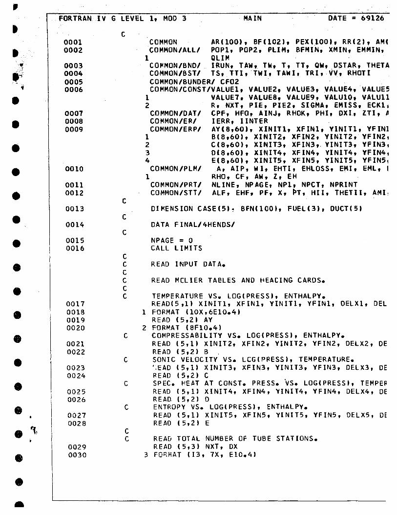
3. Computer Programme Flow Chart
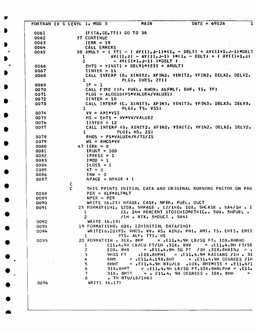
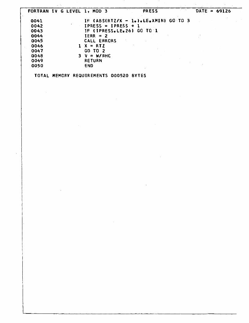
4. Computer Programme Listing (Enclosure)

1.
2.
• 3.
•
LIST OF TABLES
Ratio Table for Kerosene
Ratio Table for Shelldyne - extended for
pred ict ion •
Enthalpy Table for Kerosene Combustion

•
•
LIST OF FIGURES
1. McGi11 University High Entha1py Wind Tunnel
(simp1ified schematic)
2a. Details of Constant Cross-Section Combustion
Tube
2b. Theoretica1 Duct for Ana1ysis
3. Combustion Tube Mounted on Hot Tunnel
1

LIST OF GRAPHS
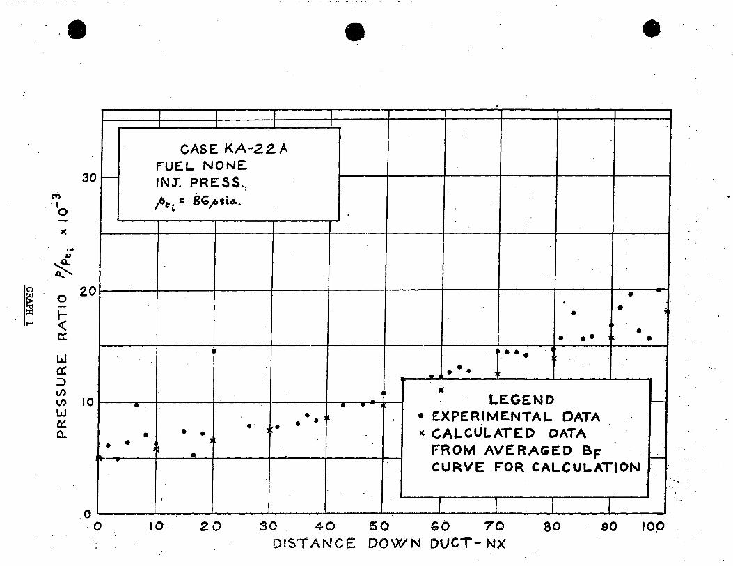
1. Results - Series KA-22A - run 0 - no fuel injection
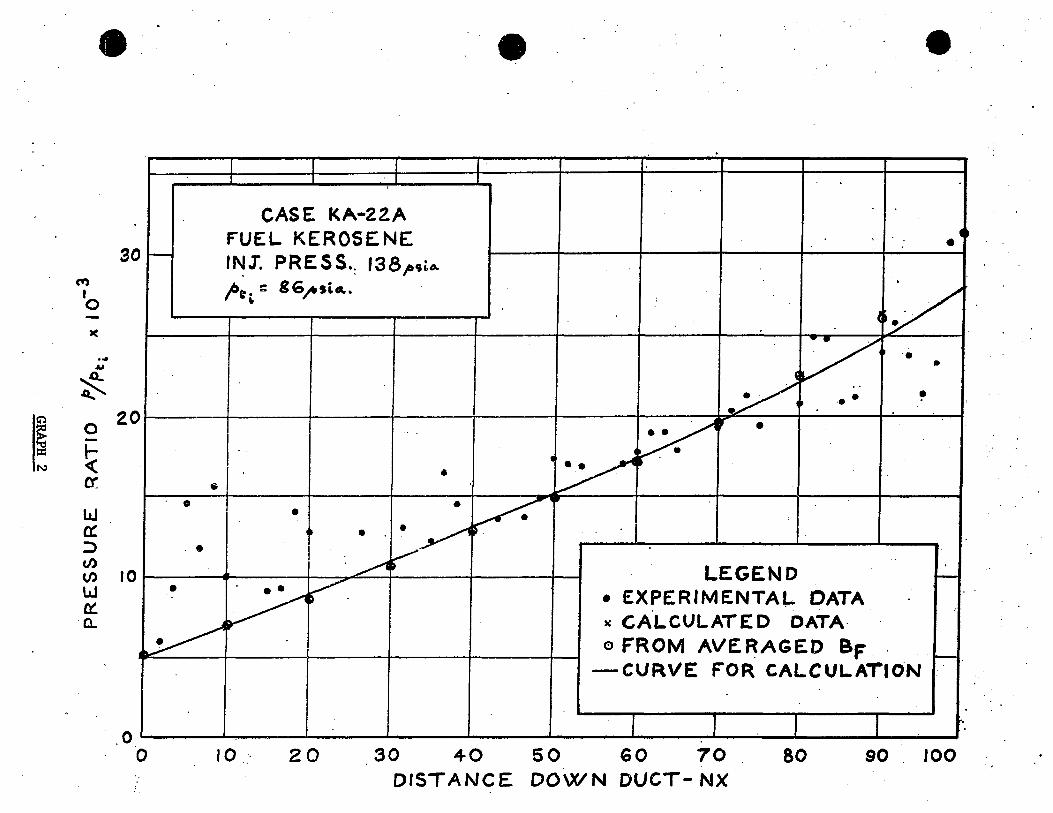
2. Results - Series KA-22A - run 1 - fuel Kerosene
3. Results - Series KA-22A - run 2 - fuel Kerosene
4. Burning factor - series KA-22A - Kerosene
• s. Results - Series SD/A-2 - run 0 - no fuel injection
6. Results - Series SD/A-2 - run 1 - fuel Shelldyne
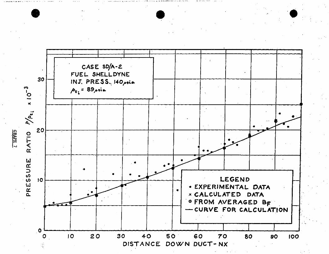
7. Results - Series SD/A-2 - run 2 - fuel Shelldyne
8. Burni~g factor - Series SD/A-2 - fuel Shelldyne
9. Prediction - Series SD/A-2 - run 3 - fuel Shelldyne
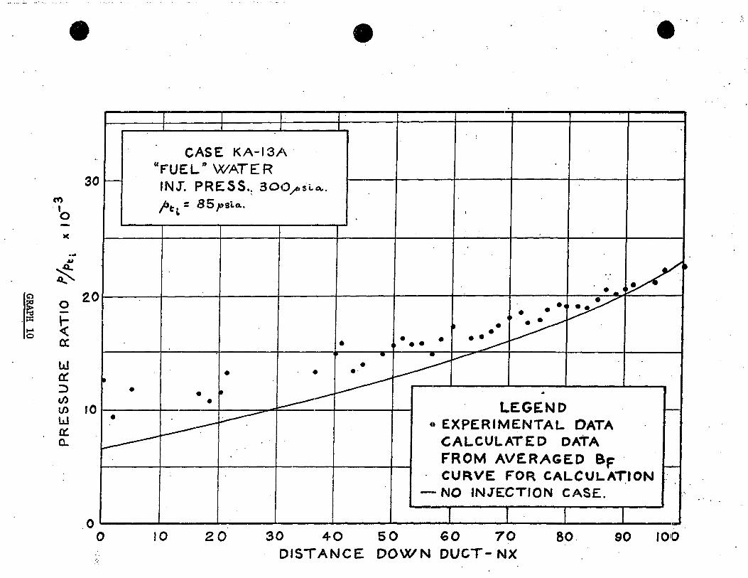
10. Test KA-13A - water injection
•

•
•
A
BF .....
F
H
NOMENCLATURE
Effective cross-sectional area for flow = Ao.tlQ. - S*
Injector nozz1e cross-sectional area
Actual duct cross-section area
Burning factor
Minimum value of burning factor - used to faci1itate convergence of iteration
Coefficient of skin friction
Specific heat at constant pressure
Non-dimensional ÏIIass entrainment rate
Environmental Grashof number
Enthalpy per mole
Compressible shape factor
H Shape factor associated with entrainment rate 'ûloi
~i Incompressible shape factor
HTR Transformed shape factor
AHI Reat released by combustion; = G.
A Hes Reat of combustion of fuel at 2SoC
K Entha1py constant
KT Iteration counter
KTT Maximum value for KT
L Reference dimension - duct 1ength
~ Mach number at out edge of boundary layer
M'NT Mass flow of fuel through in je ct or
Momentum 10ss
•
•
MODE Computer operation control variable
N" Nusselt number
NX Parameter controlling location in duct for calculation
NXT Maximum value of NX i.e. duct exit
PEX
PliM
PO
POP
POPI
Environmental prandtl number
Experimentally determined static pressure
Convergence criterion for pressure determining iteration
previous value of static pressure
Convergence criterion for iterations
Convergence criterion for iterations
POP!. Convergence criterion for iterations
Q
R
T
Reat released by combustion
Quantity of fuel burned at specified location per unit mass of air
A flow property
Gas constant for air
Effective duct radius
Static temperature
Temperature of adiabatic wall
Temperature of products of combustion
Eckert' s reference temper8ture
Wall temperature

•
•
~ Reference temperature used in combustion calculations
~T Temperature difference between duct wall and environment
V Fluid velocity
~ Velocity of fuel emerging from in je ct or
Vs Velocity of sound
~f Mass of fuel added at specified location
X A flow property, • RTiI or transformed longitudinal co-ordinate
4- Momentum parame ter
~ Gravitational acceleration
h Enthalpy of flO~l
h Film coefficient
k Thermal conductivity
L Distance down duct
1> Static pressure
A/1 Pressure drop across fuel in je ct or
crr Heat lost by radiation from duct wall
'l~ Heat flux from fluid to duct wall
(,W'" Mass flow per unit area of cross-section
tA/" " Mass flow through fuel in je ct or
:.: Dimensionless distance down duct
z Compressibility factor
. ,

•
•
oe Fuel-air ratio
/oS Bulk modulus
~ Ratio of specifie heats
b* Boundary layer compressible displacement thickness
e Emissivity of duct
e Boundary layer compressible momentum thickness
e. Equivalent incompressible momentum thickness ~
~ Fluid viscosity
~ Fluid density
~ Stefan-Boltzman constant
~v Wall shear stress
Angle of fuel injector - injection normal to duct axis is 00
Conditions at an intermediate reference temperature defined in combustion calculation
Referred to station ~
Reference conditions specified for Sutherland's la~.,
( ~ Loss of property referred to
C ),. Conditions at temperature after combustion
()~ Conditions at Eckert's reference temperature
( J, Tota 1 cond it ions t

() *
•
•
Conditions at throat of Mach 3.75 nozzle
Details of boundary layer properties are found in Reference
1

•
•
INTRODUCTION
The growing interest in propulsion at hypersonic speeds
has led to the investigation of three basic air breathing engines;
the conventional ramjet which operates with subsonic combustion,
the standing detonation wave ramjet and the supersonic combustion
ramjet (scramjet).
The standing wave engine in which combustion takes place
through a strong shockwave inside the engine appears promising, but
its oversensitive response to inlet flow conditions and internaI
pressure and temperature changes would make necessafY a complex
control system •
In a conventional ramjet, the air flow in the combustion
chamber is subsonic as a result of a normal shock standing in the
engine inlet. Excessive pressure loads and an extreme rise in the
temperature of the air are produced by this reduction in velocity.
At hypersonic velocities these effects result in severe structural
problems in the engine.
Lower temperatures may be maintained by permitting the
air velocity in th~ combustion chamber to remain at a high value,
particularly at a supersonic velocity. In the supersonic combustion
ramjet, the air flow r~mains supersonic throughout the engine.
Since the performance of an engine of this type depends on the amount
of energy which can be imparted to the airstream, energy which is in
the form of heat generated by combustion, this temperature reduction

•
•
- 2 -
leads to a more effective engine design as there is greater margin
for heat addition. Dugger (Ref. 5) and others show the theoretical
superiority of supersonic combustion in ramjet engines operating at
high external Mach numbers.
It is desirable to study the process of combustion in a
supersonic airstream under conditions as similar as possible to those
which would be found in supersonic combustion ramjet engines which could
propel a hypersonic vehicle. Briefly, such conditions are :-
i)
ii)
low static pressure (of the order of
l ~tm before combustion,) and
high total temperatures (approximately
3000~ before combustion)
The static temperature is high enough to cause spontaneous ignition
of the fuel. These are conditions at the entrance to the combustion
chamber, that is, after the velocity change produced by the engine
inlet.
The authors of many theoretical works have selected
hydrogen as fuel, Ferri (Ref. 6), Gross (Ref. 18) and Valenti
(Ref. 3) among others. Hydrogen has the highest heating value
of any fuel, a sufficiently high specifie heat to provide useful
engine cooling and relatively simple reaction kinetics. It is,
however ,awkward to store ln quantity and offers a serious E!xplosion
•
•
- 3 -
hazard.
The ease of handling, storage and avai1ability of liquid
petroleum fuels makes them very attractive as fuel for supersonic
combustion ramjets. It is, therefore, desirab1e to eva1uate the
performance of such fuels in supersonic combustion. Experimental
work has been carried out at HPL using Hydrogen (Ref. 3), as we11
as a variety of other fuels, notably TEA. Present efforts in this
field are however directed towards hydrocarbon fuels.
The purpose of this report is to devélop a numerical
calcu1ation procedure which will permit the prediction of phenomena
associated with supersonic combustion. Such a procedure wou1d then
be used in the design of the ~ombustion chambers needed for efficient
supersonic combustion.
The experimenta1 data used in this ana1ysis was obtained
during supersonic combustion tests in a cy~indrica1, constant area
duct using the HPL Hot Tunnel Facility (Ref. 15). A continuing
investigation into the field of supersonic combustion has been in
progress·at the Hypersonic Propulsion Laboratory (HPL) of McGi11
University for several yean;"

•
•
- 4 -
GENERAL CONSIDERATIONS
Investigationsin the field of supersonic combustion are
comp1icated by the simu1taneous occurrence of turbulent mixing and
chemica1 reaction. These processes do not readily 1end themse1ves
to complete ana1ysis and it is necessary to resort ta simp1ified
mode1s.
The f10w is to be assumed steady, shock free and
one-dimensiona1. Combustion is considered as a process of
simple heating with mass addition and friction. No a110wance is
made for changes in f1uid properties due to the presence of
combustion products.
In supersonic f10w through a duct of constant cross-sectiona1
area, wall friction causes a rise in the static pressure a10ng the
length of the duct. For a hot f1uid, heat 10ss to the wa11s produce
a drop in static pressure which to some extent counteracts the
effects of wall friction. However, if heat is added, as for examp1e
by combustion, a further rise in static pressure i8 produced. At
the same time, the Mach number is reduced and the f10w becomes choked
within a re1ative1y short 1ength of duct.
The amount of heat added must be as great as possible
in order to obtain effective propulsion from an engine. Two
factors 1imit the amount of fuel which can be burned : the free

•
•
- 5 -
oxygen in the flow May be entirely consumed or the duct May choke
because of excessive heat addition. In a constant area duct the
latter seems the Most likely limitation, especially considering
the high initial value of the static temperature. If earlier
combustion can be obtained as a result of better mixing (smaller fuel
droplets will be heated faster and thus cause earlier ignition) the
required length of du ct is reduced. This should le ad to a decrease
in the effect of wall friction and permit higher efficiency to be
attained since a greater amount of fuel is then required to choke
the duct.
Anotber approach would be to use a duct with diverging
walls to maintain the static pressure at a constant low value,
allowing greater heat addition before choking occurs. The limiting
factor here is unquestionably the amount of available oxygene An
additional benefit of this procedure is that the lower static pressure
could permit a lighter wall construction and so produce a saving in
overall combustion tube weight •
•
•
- 6 -
THEORETICAL CONSIDERATIONS FOR ANALYSIS
Addition of heat, in this experiment is produced
by burning a liquid hydrocarbon fuel. In order to simu1ate
conditions within the combustion chamber of the engine of a
hypersonic vehic1e the air flow is maintained at a high temperature.
The static temperature for the fluid is in fact above the ignition
temperature of the fuel so that combustion occurs spontaneously
as soon as adequate mixing takes place.
The high temperature encountered in the combustion
tube produce considerable departure of the f1uid properties from
those predicted by the ideal gas equations. The tabu1ated data
used (Ref. 10) is more accurate and quite convenient. An equation
of state incorporating the compressibi1ity factor is used in
conjunction With this. Maximum accuracy is obtained by the use
of an interpolation a1gorithm between the tabu1ated values. In
some cases, special routines are required to obtain solutions for
variables not explicitly tabulated (i.e. if the table is f = f (a,c)
to solve for c in terms of a and f.) Ca1cu1ation proceeds by means
of a series of nested iterations since it is impossible to solve the
series of equations analytically with the tabulated data.
The fuel is injected at the entrance to the duct
by a number of radial jets, as described on Page 12. This
cross-wise injection of the fuelproduces a greater pressure
rise than is the case with axial downstream injection, but
•
•
- Tl -
Szpiro et al. (Ref. 7) indicates that the method results in
faster mixing of the air and fuel. Because of this, combustion
occurs sooner and a shorter du ct can be used. The length of
duct which may be used ls limited to that which is required
to choke the flow as a result of wall friction and the heat
addition from combustion.
AlI fuel is injected at the beginning of the duct, Just
downstream of the Mach 3.75 nozzle (Fig. 2a). However, the presence
of unburnt liquid fuel in the air stream is neglected. The
properties of the products of combustion are calculated from the
tables used for pure air (Ref. 10). This assumption is discussed
further in the conclus1ôn •.
The variation in the various physical properties along
the duct is determined by the manner in which combustion is
distributed, in addition to the normal effects which occur in any
duct (friction, heat loss, etc~). A special parameter, given
the name burning factor, has been devised to describe the process
of combustion. This parameter is a derivative which indicates
the rate at which fuel is burned at each point in the tube. A
curve for the burning factor can thus be constructed showing how
the combustion is distributed over the length of the duct (Graphs 4, 8).
Mathematically it is convenient to have the burning
factor in non-dimensional, normalized forme This is achieved

•
•
- 8 -
by defining a non-dimensional duct length :-
'Je: ..t -L
where .J. is distance down the du ct and
L is total duct length.
If the amount of fuel burned up to any point in the duct
iâ F (the total amount of fuel is denoted by FI' ), then the rate
at which fuel is consumed is !~
The burning factor is now defined as
1 & --
F'f,
so that, integrating over the duct length it is evident that
1 1 1 .L F /' BF cl'" • / - cA,'X al. F'a 04. "'" . .
= 1 From such a burning factor curve, it is possible to
select an average value of burning factor for any element of duct
1ength. This forms the control over the calculation of the
combustion process.
Boundary layer growth within the duct is ca1culated
using a set of differentia1 equations deve10ped by Standen
(Ref. 4). The effect of the boundary layer is to produce
a 10ss of energy and momentum and a reduction in the effective
•
•
- 9 -
cross-sectional are a of the tube. Since the diameter of the
experimental test section is small this latter effect is significant.
In the calculation of heat loss from the duct, the thermal
capacity and conductivity of the tube wall are neglected. Since it
is assumed that an equilibrium condition has been reached, the thermal
capacity will have no effect. The tube wall is quite thin, and the
conductivity of the material far higher than the other parameters
this also has little effect on the calculations, and the wallis
assumed to be at constant temperature. The tempe rature is selected
to equalize heat flow through the boundary layer for the hot fluid
and heat loss outside the tube by radiation and free convection •
The effect of re-radiation from the surroundings is also neglected
as small (of the order of 0.1 per cent.)
The duct is divided into 100 equal subdivisions to
facilitate the calculations (Fig. 2b). The station for which
output properties are evaluated lies at the end of each subdivision,
although some of the properties u&ed in the calculation are mean
values for the duct elements considered.
The equations governing the flow are developed in
Appendix 1. They cannot be solved explicitly; however, by use
of an iterative procedure, it is possible to proceed with any
desired degree of accuracy from a known point to one farther down
the tube • Calculation therefore proceeds in steps from station
•
•
- 10 -
to station. At each station, iteration proceeds until a
satisfactory degree of convergence is obtained. The
calculated static pressure is matched to the experimental
values by mod:J;fying the burning factor. In some cases,
this proves to be impossible even when no fuel is burned.
The calculation then proceeds to the next station having
assumed no combustion. Combustion is represent~~ by both heat
and mass addition. Since both of these affect the boundary
layer and some of the flow parameters, considerable iteration
is involved to reach a solution •
When the flow in the entire duct has been computed,
the resulting curve is normalized and the specified fuel-air
ratio changed to obtain the correct fuel consumption. The
entire case is then recalculated as a prediction run showing
correct burning factor and stoichiometry •

•
•
- 11 -
EXPERIMENTAL INVESTIGATION
The experimenta1 equipment is mounted on the McGi11
University High Entha1py Wind Tunnel HT-1 (the Hot Tunnel).
This faci1ity supplies a high temperature airstream which can be
maintained at constant conditions for severa1 minutes. The air
stream is heated first by zirconia-oxide pebble bed and fina11y
by use of an oxygen-hydrogen afterburner. The air is supplied
by a group of compressors with a high pressure reservoir. The
10w pressure on the exhaust side of the system is maintained by
a vacuum system embodying two hytor-pumps, two stage steam ejectors
and a large dump tank. The nozz1e used for this experiment
provides a mass f10w of 0.04 lb/sec at a Mach number of 3.75 and
a total tempe rature of 54000R. (Ref. 16).
A diagram of the Hot Tunnel is included (Fig. 1) and
detailed information may be found in Reference 8.
The apparatus used (Figures 2a, 3) consists of a stainless
steel duct with a constant, circular cross-section. Static
pressure taps are spaced every half inchalong the duct which
is 30 inches long and 1,06 inches in internal diameter. The
downstream end of the duct vents into a larger diameter pipe which
leads to the vacuum system •
•
•
- 12 -
A pitot tube, mounted at the duct exit, is used to
obtain the exit Mach number and input conditions are known from
the test faci1ity instrumentation. The out let vents into a
vacuum system to maintain the required 10w pressure.
Fuel is introduced by means of an in je ct or block which
carries a number of suitab1e in je ct or tubes (in this experiment,
three in je ct ors of 0.008 inch diameter are used). This b10ck is
simp1y a short 1ength of duct fitted between the test section
and the air nozz1e mounted on the Hot Tunnel (see Fig. 2a).
The static pressure taps are connected through a
scan niva1ve, an automatic rotary switching device, to a pressure
transducer • The output from this drives one channel of a visicorder
oscillograph, producing a graphie record of the pressure
distribution. The other channe1s of the visicorder are used to
record temper-atu!"é:: liI~asurements from various thermocouples situated
on the outside of the test section wall and in the Hot Tunnel wa11s.
An experimenta1 series begins with the heating of the
pebb1e bed using a propane-air furnace from which heated air is
pumped down through the bed (Fig. 1). This procedure requires
severa1 hours. The dump tank is a1so evacuated during this time.
During a test run, air is b10wn up through a pebble bed, and
further heated by the afterburner. It then passes through the
nozzle into the test section and final.ly to the exhaust. The
vacuum pumps are kept operating during the test - the dump tank
•
•
- l2a -
serves to minimise pressure fluctuation. Fuel is injected at
the desired rate, which is determined by the number of in je ct ors,
their size and by the fuel pressure. The data obtained ia
recorded on the visicorder. Each series of tests includes a run
without fuel injection for comparison purposea.
Between each series, only brief heating is required
to return the pebble bed to its initial temperature •
•
•
•
- 13 -
DISCUSSION OF RESULTS
)
The data obtained is displayed in graphieal form so that
curves suitable for computer calculation may be easily produced. The
graphs show static pressure divided by input total pressure versus
the location in the duct. The curves drawn are assumed to start at
the nozzle exit pressure previously determined (a separate programme
is used to calculate flow through the nozzle) (Ref. 17). For each
series of tests a run with no injection is made to ensure that the
equipment is functioning normally. This also serves as a check on
the nozzle exit pressure •
Those runs in which fuel is injected exhibit an irregular
rapid pressure rise in the early part of the tube. Since this
feature is also present in a series of runs where the injectant is
water (KA - l3A) it appears to be associated with the process of
injection rather than with any combustion effects. The cause is
probably a departure from one-dimensional flow resulting from the
cross-wise injection, which results in the formation of a pattern of
oblique shock waves. Since it is evident from the water injection
runs, that the pressure distribution returns to the quasi one-dimensional
case after,a, short distance (Graph 10) the irregular pattern near
the inlet was disregarded and a smoothly rising curve inserted in
this region for purposes of calculation •

•
•
- 14 -
The computer ca1cu1ations produce a burning factor curve
which generates a static pressure distribution matching the input
distribution. In order to keep the number of iterations required
within reasonab1e 1imits, the burning factor is permitted a fair1y
wide degree of fluctuation from station to station.
It shou1d be noted that the burning factor, which is the
measure of the amount of fuel burned, tends to change the slope of
the~atic pressure curve as we11 as the value of the static pressure.
The short distance between stations renders the iteration process
re1ative1y insensitive, since there is 1itt1e time for an appreciab1e
change to appear in the static pressure. However, the change of
slope remains and consequent1y the effect of the energy added by
combustion is propogated downstream indicating a faster pressure rise
than wou1d otherwise occur. If the burning factor is excessive1y
high at a particu1ar station subsequent values will be depressed unti1
the effect of this on the ca1cu1ations is cance11ed out. An averaging
procedure can therefore be expected to remove these fluctuations from
the burning factor curve without affecting the resu1ting pressure
distribution significant1y. The resu1ts of the ana1ysis show that
this expectation is fu11y justified. There is 1itt1e variation
between the values for static pressure before and after averaging
(Graphs 2, 3, 6, 7) •
•
•
- 15 -
It can be seen that the burning factor values for a
given fuel fa11 in a reasonab1y narrow band so that a single
average curve can be drawn to represent each fuel. Changes in
the amount of fuel injected simp1y affect the overa11 fuel-air
ratio since the burning factor is in a11 cases norma1ized. The
static pressure curve from the combustion of any specified fuel-air
ratio can thus be predicted with reasonab1e accuracy.
The slope of the burning factor curve is simi1ar for
both kerosene and She11dyne, but there appears to be a greater
delay before the She11dyne starts to burn in appreciab1e quantities.
In both cases, an initia.1 high leve1 of combustion is followed by a
lower near uniform region and finally a gradual decrease to zero.
Combustion appears restricted to the first 4/5's of the tube, however,
this is probably a deficiency of the mode1 used to obtain the burning
factor.
A problem encountered in analysis of the results is that
the amount of fuel required to match theoretical and experimenta1
pressures does not agree with the amount of fuel injected ioto the
f10w. This fact is not altogether surprising since the computer
r~ogramme specifies only the amount of fuel whiêh is actually burned
50 that any unburned excess is not indicated. Also, if the fuel is
not burned comp1etely, (if appreciable carbon monoxide is formed for
examp1e) the value ca1culated will be too low. Genera lly , the
stoichiometric ratios calculated are in the range 20 to 40% (tables 1
and 2) Whereas the experimental values were much higher often over
•
•
- 16 -
100%. An actual value over 100% is not possible since there would
be insufficient oxygen for combustion. In fact, with the afterburner
used to provide heating there is consi~erable water vapour present
in the air, so that stoichiometric ratios over 85% are unlikely.
The extremely large amounts of fuel used in some of the
runs may also tend to disguise the effect of changes in the
stoichiometric ratio : if more fuel than can burn in injected,
the amount of the excess may not be very significant.
An explanation for the sometimes large spatial pressure
fluctuations observed along the duct is a departure from one-dimensionality.
Due to small duct diameter, the boundary layer thickness 1s appreciable
and the flow is not truly one-dimensional. In addition, the cross-wise
injection of fuel creates a region of non-uniform flow. Quite probably,
oblique shocks are formed in the region of injection am are reflected
down the tube for sorne distance. Such a shock pattern would be
repetitive between runs and the graphs indicate that this could weIl
be the case (for example series KA - 22A, Figures 2 and 3), especially
since fluctuations seem to be less for the no injection cases.
In the Shelldyne series, SD-2/A, values were available
for the fuel injection pressures used. This series shows how the
programme can be used to predict the results of combustion. Referring
to Table 2, runs 1 and 2 were analysed as previously described and an
•
•
- 17 -
average burning factor curve obtained. This curve was then used
in the predicition for run 3. The othe= factor required to predict
this run was the stoichiometric value (and hence the fuel-air ratio)
to be ca1cu1ated. The amount of fuel injected through a given
orifice configuration is proportiona1 to the square root of the
pressure differentia1. However, it has a1ready been noted that
very much 1ess fuel burns than that amount injected. It is reasonablc
to assume that the fraction of the fuel consumed is approximate1y
constant andfuerefore that the amount of fuel burned is still proportiona1
to the injection pressure. The resu1ts shown in Table 2 for runs 1 and
2 verify this assumption for the range of stoichiometry considered here •
There appears to be an upper 1imit above which further increases in
the amount of fuel injected will not cause a proportionate increase in
combustion as a resu1t of the 1imited oxygen supp1y avai1ab1e. Since
the third run for this series lies within the stoichiometric range
covered by 1 and 2 these are used as a basis for predicting the
combustion properties for this run (# 3). The stoichiometry for
run 3 is obtained from the ratio of fuel injection pressure thus
avoiding the necessity of exp1icit1y ca1culating the constant of
proportiona1ity for the amount of fuel burned. Owing to the 1imited
quantity of data avai1ab1e, such a figure wou1d have litt1e significance
in the genera1 case. The average burning factor previous1y obtained
for She11dyne (from runs 1 and 2) is used to control the calcu1ation .

•
•
- 18 -
The prediction resu1ting provides quite satisfactory agreement
with the experimenta1 resu1ts (Graph 9) obtained for this rune
To determine the range of stoichiometric ratios over
which this ru1e app1ies, and a1so to obtain accurate values of
the constant of proportiona1ity for various fuels additiona1
experimentation is necessary. However, the method shows considerable
promise as a means of predicting the resu1ts of combustion in
supersonic f10w through a duct. The concept of a burning factor
appears to be significant as a simple method of describing the
process of combustion in a supersonic duct •

•
•
- 19 -
CONCLUSION
A method has been given for calculating the fluid
properties in flow through a duct with supersonic combustion.
The method is based on the use of a computer to obtain an iterative
solution to the equations for one-dimensional flow with an empirical
burning factor to describe the process of combustion. This procedure
has been applied to a constant area duct of circular cross-section
for which experimental data was available, showing that a reasonable
degree of accuracy can be obtained. The calculation proceeds fairly
rapidly once the required input properties and stoichiometric ratio
are specified.
The burning factor curve is related to the distance down
the duct rather than to the percentage of total duct length,;;so
that similar curves could be devised to fit varying lengths of duct.
There is PQssibly little effect from changing the duct d iameter, but
further experiments are required to check this and also to deteTmine
the effect of changes in Mach number. More work is also indicated to
obtain a clearer understanding of the relationship between the actual
stoichiometric ratio and the amount of fuel injected.
The computer programme was written in as general a manner
as possible, so that several other modes of operation are possible •
The duct shape can be varied at will since it is stored as a series

•
•
- 20 -
of area ratios (inlet area is used for comparison)although a
circular cross-section is assumed. It is also possible to use
two hundred subdivisions of length instead of the one hundred used
throughout this analysis. This could lead to an increase in
accuracy, although its value is generally doubtful since the
programme is in any case restricted by the assumption of one
dimensional flow and relatively slack constraints on convergence
in iteration.
Similarly, in the interests of rapid calculation, the
presence of products of combustion is neglected. It is felt that
the accuracy gained by the use of tables giving such data would be
s~ight in the present case due to the simpl~fying assumptions already
made. Also the use of tables for products of combustion versus
stoichiometric ratio would lead to very complicated iteration
procedures.
The most promising area for further development is
probably the interaction between the fuel injected and the air
flow. It seems likely that the use of equations describing
the interchange of mome:ntum which occur where the relatively slow
moving fuel is accelerated to the free stream velocity would tead
to a closer approximation to the actual pressure curve in the early
part of the tube. The mixing of fuel and air streams is currently
b~ing studied at HPL. It would also be advisable to consider the
- 21 -
effect of the water vapour produced by the afterburner •
•
•
•
•
- 22 -
REFERENCES
1. Krieth, F., "Princip les of Heat Transfer," Scranton, 1958.
2. Shapiro, A., "The Dynamics and Thermodynamics of Compressible Fluid Flow," New York, 1954.
3. Valenti, A.M., "Spontaneous Combustion of Hydrogen in Hot Air at an Initial Mach Number of 3.86," Report 62-7, MERL; McGill University.
4. Standen, N.M., "Càculation of Integral Parameters
5 •
of a Compressible Turbulent Boundary Layer using a Concept of Mass Entràimnent," Report 64-14, MERL, McGill University.
Dugger, G.L., "Comparison of Hypersonic Ramjet Engines with Subsonic and Supersonic Combustions," Combustion and Propulsion, 4th AGARD Colloquium.
6. Ferri, A., "Supersonic Combustion Technology," AGARD Lecture Series on Turbomachinery.
7. Forde, J.M., Molder, S., and Szpiro, E.J., "Secondary Liquid Injection into a Supersonic Ai:",tream," Journal of Spacecraft and Rockets, Vol. 3, No. 8, August 1966.
8. Forde, J .M., Ahmed, A.M., and Szpiro, E.J., "The McGill University High Enthalpy Supersonic Wind Tunnel," T.N. 64-9 MERL, McGill University.
9. Lewis, C.H., and Neal, C.A., "Specifie Heat and Speed
10.
of Sound Data for Imperfect Air," USAF, Report AEDC-TDR-64-36.
Evered, R.D., Metcalf, H., and McIntyre, R.W., "Tables of the Equilibrium Composition and the Thermodynamic Properties of Air up to 6,000OK," Ramjet Department Report 3304, Bristol Siddeley Engines Limited.
•
•
- 23 -
11. Smith, M.L., and Stinson, K.W., "Fuels and Combustion," New York, 1952.
12. Keenan, J.H., and Kaye, J., "Gas Tables and Thermodynamics Properties of Air," New York, 1948.
13. Hodgman, C.P., weast, R.C., Shank1and, R.S., and Se1by, S.M., "Handbook of Chemistry and Physics," 44th Edition, Cleveland, 1963.
14. Ferri, A., "Review of Prob1ems in Application of Supersonic Combustion", Journal of Royal Aeronautica1 Society, Vol. 68, pp. 575-597, September 1964.
15. Forde, J.M., unpub1ished data and private communication.
16.
17.
Minassian, L., "High Temperature Pyrometry for Wind Tunnel Calibration," Masters Thesis, Mech. Eng. Dept., McGi11 University •
Va1enti, A.M., "A Digital Computer program for the Ca1cu1ation of Supersonic Wind Tunnel Nozz1e Co-ordinates," Memo 62-2, MERL, McGi11 University.
18. Gross, R.A. and Chintz, W., "A Study of Supersonic Combustion," JAS Vol. 27, 1F 7, Ju1y, 1960 •

- 24 -
APPENDIX 1
Derivation of equations
For the tube increment ~ - 1 to t (refer to Figure 2b)
the following equations apply :
Continuity :
toi. A~V, = .tOL •• A,_, V,_. (, ... Q,)
• where
Q; =
defining
(.A)"" = r V ;
w',_. At •• (1 + Qf)
Momentum :
where
Ws = ur· A. <il, Co-. ,- •
•

•
•
- 25 -
Energy
h·. ·~-I
Equation of State
Mollier data :
+ Op(AH,) - h,..c.,
T= ~ (}»,b)
z-g<,.,h)
To solve the momentum equations for l'. , we define
o.~ :: A 1._1 ("'_1 + Wi._1 VI._1) +Wç V, 'l" Ji - M..(.,
Thus, ,.. i :
Q.' • A.
'" . c -"
Ai.
Since l'i. =
& W' X· &. •
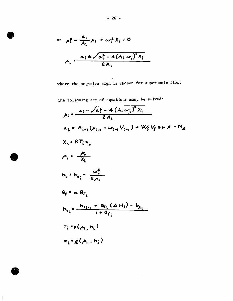
- 26 -
& 0.., &
or /Ji, - A-"'" ... "". X .. :II 0 ..
where the negative sign is chosen for supersonic flow.
The following set of equations must be solved:
~. Il' ~. - /Q.r - 4 (Ai. W:-i.)" Xi. , ~ 2 A,
x· • .. RT, %. ..
• jO. :1 l' •
• X· ,
b· • h,.-..,.,!-
" , 2. t-" ..
Q, = .. S, . ..
•

•
•
- 27 -
The boundary layer equations are (from Standen, Ref. 4)
) -2.'7J~ Hg ... G '-S 3 -S (H~ - -7 + 3' 3
.\-O·6~3 F = O· 0306 (I-I DM - a·o/
He • Tc,., H. -. T ..
e =(;t:~3 9.
H =(L)H +(2:..)-1 TR Tt C Tt
d.X T T 3 o·ut
J:;- = T~ ( Tt 1 (.:::)
cA."~_(T~~C, ei. "-M (2. La ) __ -- - -- --- + n,. .. aL", li: 2 M tA._

•
•
- 28 -
Viscosities are from Sutherland's rule
and Eckert's reference temperature is
Reat loss through the wall :.s obtained from
and q .. : Tc! 4' €
also C, _ -----
2. IOV&
Q"", =
the heat flux at a wall of temperature T~ in f10w with r~= 1 and zero pressure gradient (Shapiro II, p. 1046 -Ref. 2)
the heat 10ss by radiation

•
•
- 29 -
This was 1ater revised to inc1ude convective effects by inc1uding
the equations (Krieth, p. 306 - Ref. 1)
where
N'A = 0'02.. (Gor .. P .... )~,
N" = O.,'~ ( ...... P .. -.) V.
hL. Nu.::. -
k
} select greater
these properties are eva1uated at a mean tempe rature between T. and T .~... ( =53Û"R)

•
•
- 30 -
APPENDIX 2.
Certain Flow Properties
1. Air f10w through Mach 3.75 nozz1e
AIIt " 1)"' .463 x 10-3 ft where = = + Tt = 54000R
l'~ = 12.820 1b/ft2 = 6.06 atm
R = 1719 ft 2/sec2 - oR
Using the thermodynamics tables (Ref. 9) and the equations
z. )" +.
iteration 1eads to
Thus,
J:' 14 1: "i ·1' "~'". TIC c 2.67'·K
Y-'·2.4'3
;: ;: 81· ",04- LI./cec - ft J
eot'.., • 0·0'" l b/U.c:. .
Equations 1, 2 and 3 are from Shapiro (Ref. 2)
(1)
(2)
(3)

•
•
- 31 -
2. Stoichiometry of Kerosene
A typica1 mo1eëular formula for Kerosene is C"'e H 2.1.20
(Ref. 11).
The equation for complete combustion thus becomes
1'7·+ Oz. ... Cil" "'2.1" ---1' .,·'e02. ... "'G H,O
using the atomic weights
C - 12.0
R - 1.0
o - 16.0
it can be seen that 1 lb of fuel requires 3.429 lb of oxygen for
complete combustion. Since air is 0.23176 oxygen by weight (Ref. 10)
14.79 lb of air is required for complete combustion.
ratio is therefore 0.0676.
3. Reat Released by Combustion of Kerosene
The combustion reaction i5
Cu., Ht ,., +
" 2,·4
11,+ 0t~ , •• , C.0z. + II·' Ht,O
"~'8 1:),0'4- ZOI·t
The stoichiometric
(mo1ecu1ar weights)
•
•
- 32 -
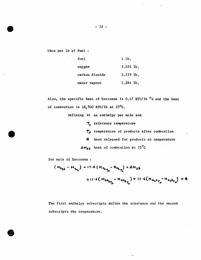
thus per lb of fuel
fuel
oxygen
carbon d ioxide
water vapour
1 lb.
3.424 lb.
3.139 lb.
1.284 lb.
A1so, the specifie heat of Kerosene is 0.47 BTU/1b oR and the heat
of combustion is 18,500 BTU/1b at 250 c.
Defining H as entha1py per mole and
To reference temperature
T)t temperature of products after combustion
Q heat re1eased for products at tempe rature
.!Hii.~ heat of combustion at 2Soc
Per mole of Kerosene :
The first entha1py subscripts define the substance and the second
subscripts the temperature •

•
•
- 33 -
Define -rc as an intermediate reference temperature sufficiently close
to ~ that a constant specifie heat can be assumed over the interval
between them.
Then, for substance ~:
(H~ - H:IIJ ):: (H" - H'k- ) + ( H x - H~ ) -T,. T. -r,. -, c T. T.
a (T,--T.)C,.." ... K~
where K",:: (H_ - H" ) -'. t •
Thus,
Go =( ti kU - HkT) • âHz.' ... 17,+ Kot, - "-, (Keot, + KW,D)
+(T,.-T.)( J?+C;"o -II·t= CC,.. 'i' C,-w o'J & w& & J
which i5 5lightly simplified by taking T.
and a term +C~1c. (T" - 2.' -Co) 15 added on the right to account
for variation of the fuel temperature from 250 C .

•
•
Assuming TA: 2000 ·R
1 T,. -Ta.I.
- 34 -
gives reasonably small values of
Relevant enthalpies are given in Table 3, (values from Ref. 12) and
substitution gives
4. Performance of fuel in je ct ors
Injection area was A ... , ~ ..!..-( ·0 ot)2-+ 1 a
Injection mass flow M, ... = A'N' /2.;0 A}:>
where r c ... 6 • , llt/ f ~1 for Kerosene
M,,,,, _4 _
::: 0·)92. 0\ 10 ./ AI'
where ~p is in lb/ft2
In most runs in this test series there were 3 in je ct ors to the above
specification •

•
•
- 35 -
5. Selected Properties for Shelldyne
Stoichiometric fuel air ratio
Mean specifie heat between 320 F and temperature 1i
Heat released on combustion
Cl al?, 2C",·4 - (T,. -2000)( 0·7 ~') +(-, 84· .. o~
+ .21' Tf - ·000 2,.0", \ T f"l.)
Density
~ = ''3·17 f. - O· 0 2.~7 Tf llf/ft)
where -rf i8 in degrees Rankine

•
•
APPENDIX 3
l DATA F'OR NE.XTtAS
SET Br(NX}= 0 NX=I,NXT
CALCULAT INITIAL
Hot z.
CALe.IN/TI
Vs, V. H 1 CAl"
NO
COUNTERS « Kï~O
Computer Programme Flow Chart
RITE IN ITIA~ DATA &
UKNING FCT
2.S
YES
WRITE
CONVERT FORCES TO POUNDALS
CALC·A,To._ Tr.RR,A_,
C «Sol.
SET /" STN.
VAUES .. POP, poPt

40
RECALe.
T .. W'
100
50
• NO YES
KT=KT+I
YES NO
PO =.;-6
KT=O
40 lS
•

NO YES
NO YES
NO YES
NO YES
NO
YES NO • BF= 0
40 Z5
zoo
•

NO
• NO
NO
POP=POPt.
•
NO
POP=POP2.
BF(N){)= 6FCNX-I)
YES

• NO
•
SUBROUTIN SETS DATA FOR FUEL
YES
READ FIRST CARO OF' INPVT DAiA
RESET INITIAL VALUES
CA!.!. EXIT
NO
NORMALIZ eVRNING
FACTOR
PUNCH B F' 8. FUEL-AIR RATIO
(j)
~ 1-'
' .•
C"t) , 0
)(
... ~
~ 0 -~ 0:
W cr. :> cl) (/)
W
" Cl.
30
20
10
o ·0
-
.. •
• • ..
• e
1 1 J 1 . 1 1
:
CASE KA-22,A FUEL NONE IN.T. PRESS .. Ptt = 8G}ttto..
, ' :
• .. . • • ~ ,
~ • • •• • , ... -.
••• • Je
• • LEGEND 1--
• • EXPERIMENTAL OATA • . •• • • • • . " CALCULATED DATA
'r- FROM AVERAGED BF Q • 1-
CURVE FOR CALCULATION ".
-_ ... - .. _--j--~ .. _ ..... ~ -~- . _. 1 1 1 .
10' 20 30 40 50 60 70 80 90 10P DISTANCE DOWN DUCT- NX
§ N
• • e
1 1 . 1 1
CAS E KA-22.A FUEL KEROSENE 4 • 30 f--
'~J". PRESS,: f38,o'iA C"t)
1 0
)(
~tt = 8 Grs''''' : l '/ ...
oU
~ 0
20 -~ ~
V • •
.;./ • • • . .
V· • . ' . •• •
• 'V ~
W Cl: ::> (/) Cf) 10 W ~ a..
• • .. ~ •
• • ~~ r
• • ~ ~ LEGEND 1--
• V ~ . • EXPERIMENTAl- OATA
~ " CALCULATED DATA· a FROM AVERAGED BF ..
1-. -CURVE F'OR CALCULATION
,
1 1 o o 10· 20 30 40 50 60 70 80 90 tOO
DISTANCE DOWN DUCT- NX
,

Ci)
~ w
• • •
t'I)
1 0
)(.
... .u
~ 0 -~ 0:
W
" ::> f.!) Cf)
W (( 0..
1 1 1 . 1
CASE KA-Z,ZA .
F"UEL f<EROSINE 30
. , r- I N.T. PR ES S.: '87 ,oli.o..
• V-~tt = 8G ..... ia.. \ •• • y.
20
l/'..) V· .. • •
• .. ~ t •
V /" ~ •
• .~ •
10
.. V •
~ • • • ~ ~ .
• LEGEND t--
~ • EXPERIMIENTAL DATA
V " CALCULATED DATA , Ci) FROM AVERAGED. BF . .
i--
-CURVE FOR CALCUI-ATION .-
1 .
. . ~. 1 1
~------_._---o o '0 20 30 40 50 GO 70 80 90 100
DISTANCE DOWN DUCT- NX

.... ~~_ ..... -_._ ..... __ ._--.--_._-_ .. - -_. --_.- -----._---_.-- --------,
~ ::c .p.
•
LA. cO
• OC 0 1-v ~ ~ z -Z 0:: ::> co
:-
. 6
5 .
. -
4
"
3 (1~
r z.
o ·.0
\ II
• r
~
• 1 - 1 1 1
BURNJNG FACTOR CASE KA 2.2.-A FUEL KEROSINE
1 1 1 1
LEGENO '.
. INJ'. PRESS. J 38,-, ... • , 87 l"': •
AVERAGED B,CURVE --
~ ........ ~ ~ac.. . .-. . .. " '"
" .... x ~
~ ~
~ ,," )(
~,," . ;JI Jr)( • •
. " " • • x • • . ... . ." . . •• • , ••
~ . : ... ". i
Je" -----~
'2. . ·3 ·4 ·5 ·6 ·7 ·8 '9 OISTANC E DOWN DUCT - . x
.-
!--
'--.
..
,'·0

CO)
.. ~ ::II VI
• • .' 1 1 1 1 .
1 1 ,
CASE sOjA-2.
('t)
1 0
)(
... 41
~ 0 -~ 0::
W cs:: :> en c.J)
W 0:: 0.
FUEL NONE 30 :- INJ". PRESS ..
Pt i. = 8.9 ,6~i.Q..
ZO 1
•
10 1
~ ~
~····_·1 o
o
• • , 1
1
'0 20
.-
' .
:
, '
• • l
• • 1 • • • •• • • .. .
• ~ • •
• 1( . LEGEND 1--• ft
• (xPERIMENTAL OATA • .. ~
11 CALCULATED DATA . ~.
• FROM AVERAGED BF .
1-
CURVE FOR CALCUL-ATION
l :3'0 40 50 60 70 80 90 100.
D.STANCE DOWN DUCT- NX

(j')
~ ::t:
'"
•
('t)
t 0
)(
... .III
~ 0 -~ CC
W cr: :> cf) Cf)
W C! c..
30
20
10
I
1
o '0
r--
• • .. •
• e·
1 1 1 . .1 1
CASE SD/A-2 FUEL SHELLDYNE INJ'. PRESS.: IOO}.~o...
1'1: ~ = 89,.s1.0...
C ,
.. A . • 1
Y • .' •
. . y ,
.. ~
• ..,...--P ~
V~ • r • • LEGEND l-
~ ~ • EXPERIMENTAL OATA
~ Je CALCULATED DATA·
~ • ~ e FROM AVERAGED BF
~
- CURVE F'OR CALCULATION
l 10· 20 30 40 50 60 70 80 90 100
'DISTANCE DOWN DUCT- NX
G'l ,.~
:::r:: -...J
• '
('1')
1 0
)(
... ~
~ 0
l-« a::
w a: ::> f.I)
'CI> W OC Q.
30
20
10
"
o o
'.- .. , ............ _ ........... _ . ..-.. , ........... -;
• ' • l l'
1 (
CASE SD/A-t-FUEL SHELLDYNE
- 'N.T. PRE S S.~ 140,..,,0-Pt:" = 89jÔc,,,
\
• , , v. • '~
v. V
'.~ " ,. p ~r-
•• • ., ~
LEGEND t--
V V • EXPERIMENTAL O,~TA • . V x CALCULATED DATA
• ::::""":"1 '<:) FROM AVERAGED BF' , t---
- CURVE FOR CALCULATION ,
l ' , ~-l--'0 20 30 40 50 60 70 80 90 100
DISTANCE DOWN DUCT- NX

-....!., .... _ .. ____ ._ .. _ ... , .. _.~ ... _._ ... __ .... _. _o.
~ ::Il 00
•
1.&. dl
• cr: 0 J-u
. ~
\!)
z -Z 0:: ::> Cl
.~:~
(,
5
4
3
z.
o o
• •
..
•
• 1
•
.,
-- ---_·_---~-------_·_--oo----~-
• • x
. 1 1 1 Î
BURNING FACTOR
" 1-CASE SD/A- 2-FUEL SHELLDYNE 1--
'" 1 1 1 1
1\ " LEGE.ND 1-
( J< INj. f'RESS. 100 p'ltL-. le
" 1 J 40 ~ 'It'~. • li.
Il . AVER~GED BF CURVE -)( " •
• • . ~ e •••••
.~ ,," " ,,_ x
" " " 1,. • •••• " . " • Il ,c
~ .- •• • ~ , .. _. 1 "- _'lot . '-~ • ~ • •• • wc • "
..
"". "" J( ~ Il,, - ~. L
'2 .3 ·4 ·5 -6 ·7 . -8 '9 .·0 DISTANC E DOWN DUCT - :Je

..:.. .. --... ............ , . ...-.---- ..... --------- ----
, " ~ ::tI
"\0
•
('1)
1 0
)(
... AI
~ 0 -~ CI
w·
" :l fi) en w
" 0..
"
:30 1--
20
10
~ . 1 o o
•
'"
• , . '." J , ' ., 1
1 , CAS E SO/A- 2.
FUEL SHELLDYNE . 1 N .T. PRE S S. 1 2 0 Jt 4j .. o. •
Pt. = 8 S J'st 00-. ,
)
. " • ~ • • -.
4 •• • • , ' .-lJ -• -4 , -.
• • • 4
• • c LEGEND ~
( . - EXPERIMENTAL OATA 4
• C • CALCULATED DATA • • • .4
e FROM' AVERAGED BF c 1-'
••• CURVE FOR CALCULATION • 'f , ..
1 1 -1- .- ·-1-- •..
. 10 20, 30 40 50,"60 70 80 90 '100, DISTANCE DOWN DUCT- NX
en
~ ,.::Z::
~ 0
• • .' J'
.L J. J :
CASE KA-13)\·
"FUEL" WATER 30 r-- INj. PRESS.: 30()/",si.",.
('f) , 0
l't: t = 85I'së.o.. \
)(
.4
U
~ 0
20 -~ 0::
., V • • • ~ • • 1
~ . ~ • • • • • • • • ~
W a: :> (/) lf) 10 W
.. ~~ • • . . ..
• ~ • • /t ~:::
• • LEGEND r-• ~ •• EXPERIMENTAL DATA
" a. ~ V-- CALCULATED DATA
o o JO 20
FROM AVERAGED BF -CURVE FOR CALCULATION . -- NO INJECTION CASE.
l--.--~. .-30 40 50 60 70 80. 90 1010
DISTANCE DOWN DUCT- NX

•
•
l -< bI .. ..
~ < lai 1-.,
Z 0
f- « U 1aJ lai f-fi)
~
~ Cll:Z
ê~
lit .,.
III a • 0 z ... III >
.: Q :t .. z .. z 0 Z lit u
~ ~ • tt. 0 lit lai C .. ... ., A t- Ilt Z ... :)z iai oC <c Q z ~ ...
)( 0 U
III
le --< .. t ~
1 ..1
Z Q ~ <
1
lLI ... m " .. ! l&l z
~ z< ~ 5 - ..J .... ID 0 u <.J ID a
~ laIu lù ~ x). D- o
\1 ... ., ...
• Cc ~o '" z~ ~
c biC lit aoC lit ZI. ~ 0 .. le " .. ..
~ 0 .,
FIGURE 1 - McGill University High Enthalpy Wind Tunnel

•
•
INJECTOR BLOCK
TEST SECTION
1 rPRESSURE TAPS- 0'5 IN.
SPACING
Z·O· ...... ~~----------30· () --------.,.
FUEL INJECTOR - NUMBER OPTIONAL
FIGURE lA - Details of Constant Cross-Section Combustion Tube
o l i,- J L N;I<.T-J
FIGURE 2B - Theoretical Duct for Analysis
T

•
FIG. 3 COMBUSTION TUBE • 1nstalled on a Mach 4 nozzle.

.FIG., 3 COMBUSTION rruBE

TABLE 1
RATIO 'EABll.ELEOR KEROSENE
.., Oc. RATIOS RUN INJECTION %
1F PRESSURE STOICHIOMETRIC (RUEL-AIR RATIO) ee." I;h-., CASE KA-22A
• 1 138 32 0.02457
2 187 38 0.02887 1.175 1.165
CASE KA-23A
1 138 34 0.02598
2 162 40 0.03058 1.180 1.081

• • •
TABLE 2
!
RATIO TABLE FOR SHELLDYNE - EXTENDED FOR PREDICTION
'-., RATIOS
RUN INJECTION - ~ FOR % ' >
4fo PRESSURE STOICHIOMETRIC (FUEL-AIR RATIO) .... ;:,; ~./-~ STOICHIOMETRIC -oe., ~ -" l
1 100 22 0.01671 1 1 - -2 140 26 0.01964 0.18 0.18? .01975 26
3 120 - - - 1.098 .01830 25

• • •
TABLE 3
ENTHALPY TABLE FOR KEROSENE COMBUSTION'
K = C,.a( .... t .. SUBSTANCE ' H5370
R H20000R H15000R H25000R H2000 - Hn ) .. J _ ... , •• K'O
OXYGEN 3,725.1 15,164.0 11,017.1 19,443.4 11,436.9 8.4262
CARBON 4,030.2 21,018.7 U.,576.0 27,801.2 16,988.5 13.2252 DIOXIDE
WA'rER VAPOUR 4,258.3 17 ,439.0 12,551.4 22,73504 10,184.0 13.1807
(values in BTU/1b-mo1e)
,
•
• • • • • • • • • • • • • • • 'il •
• •
. fORTRAN IV G LEV EL 1:' MOD 3 MAIN DATE = 69126
0001 0002
0003 0004 0005 0006
0001 OOOS 0009
0010
0011 0012
0013
0014
0015 0016
0011 001S 0019 0020
0021 0022
0023 0024
0025 0026
0021 002S
0029 0030
C
C
C
C
C
COMMON AR(100), BfCI0l), PEXliOO), RRCl), AMC COMMON/ALLI POP1, POPl, PlIM, BfMIN, XMIN, EMMIN,
1 QLIM CO~MON/BNOI IRUN, TAW~ TW, T, TT, QW, DSTAR, THETA COMMON/BSTI TS, TTI, TWI, TAWI, TRI, VV~ RHOTI COMMON/BUNDER/ CfOl COMMON/CONST/VAlUE1, VALUE2, VAlUE3, VAlUE4, VAlUE~
1 VAlUE7, VAlUEB, VAlUE9, VAlUI0, VAlUll 2 R, ~XT, PIE, PIEl, SIGMA, EMI~S, ECKl,
COMMON/DATI CPf, HfO, AINJ, RHOK, PHI, DXI, ZTt, A COMMON/ER/ IERR, liNTER COMMON/ERPI AY(S,60), XINITl, XflNl, YINIT1, YfINl
1 BCS,60), XINIT2, XFIN2, YINIT2, YFIN2, 2 C(S,60), XINIT3, XFIN3,. YINIT3, YfIN3, 3 D(S,60), XINIT4, XFIN4, YINIT4, YFIN4, 4 ECS,60), XINIT5, XFIN5, YINIT5, YFIN5,
COMMON/PLMI .At AIP, WI, EHTI, EHLOSS, EMI, EMl, 1 1 RHO, CF, AW, Z, EH
COMMON/PRT/ NLINE, NPAGE, NPl, NPCT, NPRINT COMMON/STTI ALF, EHF, PF, X, ~T, HII, THETII, AMII
DIMENSION CASE(5)~ BFN(100), FUELC3', DUCT(5)
DATA FINAL/4HENDS/
NP AGE = 0 CALL lIMITS
C READ INPUT DATA. C C READ M(LIER TABLES AND HEACING CARDS. C C TEMPERATURE VS~ lOG(PRESS), ENTHAlPY.
READ(5,1' XINIT1, XFIN1, YINIT1, YFINI, DELXI, DEL I FORMAT (lOX,6E10.4)
REAO (5,2. AY 2 FOR~AT (SFIO.4)
C COMPRESSABILITY VS. LOG(PRESS), ENTHALPY. REAO (5,1) XINIT2, XFIN2, YINIT2, YFIN2, DElX2, DE READ (5,2) B
C SONIC VELOCITY VS. lCG(PRESS), TEMPERATURE. ~EAD (5,1' XINIT3, XFIN3, YINIT3, YFIN3, DElX3, DE RE AD (5,2) C
C SPEC. ~EAT AT CONST. PRESS. ~S. LOG(PRESS), TEMPEP READ (5, U XINIT4, XFIN4, YINIT4, YFIN4, DELX4, DE RE AD. (5, 2) D
C ENTROPY VS. LOGlPRESS), ENTHALPY.
C
READ (5,1) XINIT5, XFIN5, YINIT5, YFIN5, DELX5, DE RE AD (5,2) E
C REAu TOTAL NUMBER OF TUBE STATIONS • READ (5,3) NXT, DX
3 FORMAT (13, 7X, EIO.4'

tATE = 69126 19/31/45
1., RRC2', AM(2) (MIN, EMMIN, SLIM, HIlIM~
OSTAR, THETA, CP iv~ RHOTI
~lUE4, VALUE5, VAlUE6, ~lUIO, VAlU1l, EMISS, ECKl, ECK2, ECK3
• OXI, ZTI, ALFMlT
VINIT1, YFINl, OElXl, DELYl, INIT2, YFIN2, OElX2, DElY2, INIT3, YfIN3, OELX3, DELY3, INIT4, YFIN4, OElX4, DElY4, INIT5, YFIN5, OElX5, OELY5 , EMI, EMl, EM, W, EHT, V,
NPRINT THETIl, AMI,' DX
OUCT(5'
L, DELXl, DELYl
_PY. ~2, DElX2, DELY2
~TURE.
~3, DElX3, DELY3
RESS', TEMPERATURE. N4, DELX4, DELY4
N5, DELX5, DELY5
PAGE 0001
------------------ Mc G 1 L L UNI VER SI T Y COMPUTING CENTRE ----'

FORTRAN IV G LEVEL 1, MOD 3 MAIN
C C READ AREA DISTRIBUTION.
0031 READ (S,43' DUCT 0032 43 FORMAT (SA4) 0033 READ (S,4) (ARCI), 1 = 1, NXTI 0034 4 FORMAT (lOF8.S,
C C READ BURNING FACTOR.
0035 RE,AO (5,4) (Bf(l), 1 = l, NXT)
0036 0037
C
C
READ (5,24) CASE, MOCE, NPRI~T, NP1 24 fORMAT (5X, 5A4, 6X, Il, 46X, 211'
DATE = 69126
C MODE = 0 REACS COMPLETE B f ANC ITERATES. C 1 READS 2 ENTRY B f AND ITERATES. fOR NX.GE.3: C Bf(NX-1) •
. C 2 READS COMPLETE B f AND PREDICTS WITHOUT ITER~ C TASLE MUST BE OMITTED FROM DATA. C 3 STARTS THE COMFUTATION WITH A BURNING FACTOR C ENTIRELY EQUAL TO ZERO. C 4 ACCEPTS BF = 0 AND OOES NOT ITERATE fOR IT. C C C READ EXPERIMENTAL STATIC PRESSURE.
0038 27 IF (MODE.EQ.2) GO TO 34 0039 READ (5,5) (PEX(I)~ 1 = 1, NXT) 0040 5 FORMAT (10f8.1'
C C READ INPUT VARIABLES.
0041 34 READ (5,6) FUEL, PF, TF, AlF 0042 6 FORMAT (2A4, A2, 3EI0G4) 0043 READ (5,7' HII, THETII, AS, AMl i PS, PTS, TTI 0044 7 FORMAT (lOX, 7EIO.4'
0045 0046
0047
0048 0049 0050 0051 0052
0053 0054 0055 0056 0057 0058 0059 0060
C C
C
C
C
CALl DATA STORAGE SUBROUTINES. CALL DATA CAll VALUES
KTT = 8
IF (MODE.NE.3) GO TO 48 0049 1 = 1, NX T
49 BF ( 1) = O. it8 READ (5, 100) TS
100 FORMAT (EI0.4'
PLGI = AlOG10(PTS*VAlUE4/VAlUEl) El = (PLGI - XINITl)/DELXl II = El El 1 = II DELT = El - EII II = II + 1 DO 37 J=I,60 TA = AY(II,J' + OELT*( AYlII+l,J. - AY(II,J) •

69126 19/31/45
=OR NX.GE.3: BFINX) = [THOUT ITERATION. PEX
14 ING FACTOR CUP. VE
TE FOR IT.
TI
1) •
PAGE 0002
...
--------------- Mo G 1 L L UNI VER SI T Y C""'UTING CENTRE ~
.,
• • ,fi
• 'il • • • • • • • • • • • • • • • .'
• • ...
'FORTRAN IV G LEVEL l, MOD 3 MAIN DATE = 69126 1
0061 0062 0063 0064 0065
0066 0061 0068
0069 0010 0011 0012 0013
0074 0075 0016 0077
0078 0079 0080 0081 0082 0083 0084 0085 0086 0087
C C
0088 0089 0090 0091
0092 0093 0094
0095
0096
IFeTA.GE.TTI. GO TO 38 31 CONTINUE
IERR = 19 CALl ERRCRS
38 AMULT. ~ ( TTI - e AYCII.J-l'*C1. - DELT. + AYCII+l,J-l'*OELl 1 AyeII,JI - AYClI,J-l) '*(1. - DELT' + ( AY\II+l,J) 2 - AY(II+l,J-l) )*OElT ,
EHTS = YINITl + DELY1*CEtI + AMULT' IINTER = Il CAll. INTERP (B, XINIT2! XFIN2, YINIT2, YFIN2, OELX2, DELY2,
1 PlGI, EHTS, lTI) IF = 1 CAll FIRE (IF, FUEL, RHOK, ALFMlT, EHF, TS, TF' PlGI = AlOGlO(PS*VALUE4/VALUEl' II NTER = 10 CAll INTERP (C, XINIT3, XFIN3, YINIT3, YFIN3, OElX3, OElY3,
1 PLGI, TS, VSS, VV = A.,I*VSS HS = E~TS - VV*VV/VAlUE2 Il NTER = 12 CALL INTERP (B, XINIT2, XFIN2, YINIT2, YFIN2, DELX2, DELY2,
1 PLGI, HS, lS' RHOS = PS*VALUE4/R/TS/lS WS = RHOS*VV
47 IERR :: 0 IRUNT ; 100 IPRESS = 1 IMOD = 1 IlOSS = 1 KT = 0 INW = 0 NPAGE = NPAGE + 1
THIS PRINTS INITIAL CATA ANO ORIGINAL BURNING FACTOR ON PAG PER = ALF*ALFMLT NPER = PER WRITE (6,23' NPAGE, CASE, NPER, FUEL, DUCT
23 FORMAT(lHl, 120X, 5HPAGE , I2/lHO, lOX, 5HCASE , 5A4/lH , 1 1 13, 24H PERCENT STOICHIOMETRIC., 50X, 5HFUEL , 2 /lH , 87X, 5HDUCT , 5A4'
WR 1 T E ( 6 , 19 ) 19 FORMAT(lHO, 60X, l2HINITIAl DATA/lHO'
WRITE(6,20'PS, RHOS, VV, AS, AINJ, PHI, AMI, TS, EHTS, EMIS 1 PTS, ALF, TTI, HS
20 FORMAT(lH , 31X, 8HP = ,E1l.4,9H LB/SQ FT, 10X,8HRHO 1 Ell.4,9H LB/CU FT/lH ,31X, 8HV = ,Ell.4,9H FT/SE 2 lOX, 8HA = ,Ell.4,8H SQ FT /IH ,3IX,8HAINJ =, 3 9HSQ FT ,lOX,8HPHI = ,Ell.4,9H RADIANS /lH , 31 4 8HM = ,Ell.4,19X,8HT = ,Ell.4,9H DEGREES /lH 5 8HHT = ,Ell.4,9H BTU/LB ,lOX, 8HEMISS = ,EI1.4/1 6 3IX,8HPT = ,Ell.4,9H LB/SQ FT,10X,8HALPHA = ,Eli. 7 3lX, 8HTT '=, Ell.4, 9H DEGREES, 10X, 8HH = 8 , 1H BTU/LB/lHO'
WRITE (6,11'

69126 19/31/45
v ( II + l, J-l , *DE L T ) , Il ( 'i. + ( A TC 1 1 + l , J )
, OELX2, DELYZ,
TF'
, OElX3, DELY3,
:, OELX2, DELY2,
4G FACTOR ON PAGE ONE.
~SE , 5A4/1H , lOX, , 50X, 5HFUEL , 2A4, A2
, TS, EHTS, EMISS,
FT, 10X,8HRHO =, ,Ell.4,9H FTISEC ,
,31X,8HAINJ = ,Ell.4, RADIANS /lH , 3lX, 4,9H DEGREES IlH ,3lX, EMISS = ,EIl.4/IH , ,8HALPHA = ,Ell.~/lH ,
lOX, 8HH = , EII.4
PAGE 0003
--------------- Mc G 1 L L UNI VER S 1 T Y COMPUTING CENTRE ---.....1

• • • • • • • • • • •
• • • •
fORTRAN IV G LEVEL 1, MOD 3 MAIN DATE = 69126
0097 0098 0099 0100
0101 0102 0103 0104 0105
0106
0107 0108 0109 0110 0111 0112 0113
0114 0115 0116 0117 0118 0119 0120 0121 0122 0123 0124 0125
0126 0127 0128 0129 0130 0131 0132 0133 0134 0135 0136 0137 0138 0139 0140 01 J.1 ... ~ ...
11 FORMATCIHO,51X,29HORIGINAL BURNING FACTOR TA8LE' IF (MODE.NE.l' GO TO 31 WRITEC6,30' BF(l), BF(2)
30 FORMAT CIHO, 64X,4HNONE/1H ,40X,8HBF(1' = , f7.5, 10H Bf 1 F7. 5'
GO TO 32 31 WR 1 T E C 6 , 18 H B F« 1), 1 = l, N X T ) 18 FORMAT (lH , 16X, 10flO.5'
IF t·MODE.EQ~~l WRITE (6,35' 35 FORMAT (lHO/1HO, 61X,10H---------/1H ,61X,10HPREDICTIC
1 61X, 10H----------, 32 NLINE = 59
C C INPUT CONVERSION POINT. C THE UNIT OF FORCE BEYOND THIS POINT IS THE POUNDAL.
C C C
PS = PS*VALUE4 PTS = PTS*VALUI:4 PF = PF*VALUE4 IF (MODE.EQ.2' GO TO 41 DO 16 I=l,NXT
16 PEX(I' = PEXCI.*VALUE4 41 CONTINUE
********************************************************
RHOTI = PTS/ZTI/TTI/R TAWI = VALUE5*(TTI - TS' + TS TWI = VALUE8*TTI TRI = ECK1*TWI + ECK2*TAWI + ECK3*TS RSQD = AS/PIE RRt2' = -(SQRT(RSQO" AORIG = AS*AR(l) RSQD == AORIG/PIE RRC1' = -SQRTtRSQO) EMURI = SOUTHITRI) EMUTI = SOUTH(TTI) CFI = .246*(VV*THETII*RHOTI/EMUTI)**l-.26B'*TS/TRI*tTRIJ
1 2'*«TTI + 198 •• /lTRI + 198.),**t.268)/EXPt1.56*Hl Hel = TWI/TS*HII + TAWI/TS - 1. THETAI = TTI*TTI*TTI/TS/TS/TS*THEïii DSTARI = HCI*THETAI A ~ PIE*(-RR(I' - DSTARI'*(-RR(I' - OSTARI' NX = 1 POP = paPI IRUN = 1 AIP = PIE*( -RR(2' - DSTARI ,*( -RR(2' - DSTARI , EMS = AIP*( PS + Ws*VV ) EHTI = EHTS WI = WS EMI = EMS PT = PTS X = TS*R*ZS T = TS Tw = TnI
'-----------------------~ .. _.

·26 19/31/45
;, 10H Bf' 2) = ,
HPREDICTION/1H t
DAl.
:******************
ITRI*(TRI/TTI)**(.40 XP(1.56*HII.
1 •
PAGE 0004,
•
-------------- McGlll UNIVERSITY COMPUTINGCENTRE ------'

• ;
• • • • • • • • • • • • • • • • •
" FORTRAN IV G LEVEL l, MOo 3 MAIN DATE = 69126
0142 0143 0144 0145 0146 0141 0148 0149 0150 0151 0152 0153 0154 0155 0156 0151 0158 0159 0160 0161 0162 0163 0164 0165 0166 0161 0168 0169 0110
0171 0172 0173 0174 0175 0116 0117 0178 0179 0180
0181 0182 0183 0184 0185 0186 0187 0188 0189 0190 0191 0192 0193
AW = -PIE*oX*RRll.*2. EML = .5.CFI*AW*RHOS*VV*VV EHLOSS = EMISS*SIGMA*AW*TWI**4/WI/A/VALUI1 CALL PRESS CP, PLOG, Tt BFCNX), NX)
8 CALl TEMPER (PLOG, T, TT, RHOT, GAMMA, CP, TAW = VALUE5*(TT - T' + T
40 CALL BCUND(NX, RHOT' CALL WALlS(NX, NWAL' IF (NWAL.EQ.O' GO TO 39 INW = INW + 1 IF (INk.LT.40' GO TO 40 IERR = 18 CALL ERRORS
39 INW = 0 IRUN = IRUN + 1 IF CIRUN.LT.IRUNT' GO TO 9 CALL ERRORS GO TO 12
9 IF (KT.GE.KTT' GO TO 10 KT = KT + 1
Il PO = P i3 CAlL LCSS (P, PLGG, T, BF(NX), NX'
GO TO 8 10 IF (ABS(P/PO - 1.'.GT.PLIM' GO TO 11
KT = 0 IF (MOOE.EQ.2' GO TO 12 IF (ABS(PEX(NX'/P - 1 ••• LE.POP) GO TO 12 IF «MODE.EQ.4).AND.(BFlNX).EQ.0.)' GO TO 12 IFeeMODE.EQ.3).AND.eBF(NX'.EQ.0.)) IF«PEXINX) -P'*100./PE
1 -POP*100.)12,12,45 IF «BF(NX'.LE.BFMIN'.AND.IP.GT.PEX(NX)', GO TO 46
45 BF (NX, = BFMIN 25 CALL ~CDIFY (P, PLOG, T, NX,
GO TO 8 46 BF(NX, = O.
CALl LGSS (P, PLOG, T, BF(NX), NX' GO TO 8
12 cap = P/VAlUE4 COPT = PT/VALUE4 CALl PRINTO (NX, COP, COPT, RHO, T, TT, TW, EH, V, AMel),
1 cP, DSTAR, CF, QW. NX = NX + 1 IF eNX.GT.NXT) GO Ta 42 IF «NX.GT.2'.AND.eMODE.EQ.l') BF(NX' = BF(NX-1' IF eeNX.EQ.6'.AND.eNXT.EQ.100)' POP = POP2 IF «(NX.EQ.11'.AND.(NXT.EQ.200.) POP = POP2 CALl FIRE (IF, FUEL, RHOK, ALFMlT, EHF, T, TF' AIP = A AM(2' =AM(l) EHTI = EHT WI = W EMI = EM IRUN = 1 AORIG = AS*AReNX)
69126 19/31/45 PAGE 0005
1
2 NX' -P'*100./PEXeNX'
o Ta 46
\,."
EH, V, AMel), GAMMA,
NX-l t
TF)
---------------- McGILL UNIVERSITY COMPUTINGCENTRE --_ .....

• FORTRAN IV G LEVEL l, MOD 3 MAIN DATE = 691.26
• 0194 RR(2' = RR( 1)
0195 RSQD = AORIG/PIE
• 0196 RR(1' = -SQRTCRSQO' 0197 A = PIE*(-RR(l' - OSTAR'*C-RR(l) - OSTAR'
• 0198 GO TO 13
• 0199 42 IF CMODE.EQ. 2. GO TO 33 C .. 0200 WRITE (7,36) CASE, MODE
• 0201 36 FORMAT (5HCASE , 5A4, 1X,5HMOOE , Il) 0202 CALL S MOT (ALF' 0203 MODE = 2
• 0204 PS = PS/VALUE4 0205 PTS = PTS/VALUE4 0206 PF = PF/VALUE4
• 0207 GO TO 47 0208 33 READ (5,29' FINISH, CASE, MODE, NPRINT , NP1 0209 29 FORMAT CA4, lX, 5A4, 6X, Il, 46X, 211.
• 0210 IF (FINISH.NE.FINAL) GO TO 27 0211 WRiTE (6,44' 0212 44 FORMAT (lH1'
• 0213 CALL EXiT 0214 END
• TOTAL MEMORY REQUIREMENTS 0OlD6C BYTES
• • • • • • • • • • • •

691.26 19/31/45 PAGE. 0006
--------------- Mc G 1 L L UNI VER S 1 T Y COMPUTING CENTRE •. ----1

~ •
~ 01
t
• • • • • • • • • • • • • • • --
fORTRAN IV G LEV EL 1, MaD 3 PRESS DATE = 69126
0001 C
'C C
0002
0003
0004 0005 0006
0001
0008 C
0009 0010 0011 0012 0013 0014 0015 0016 0011 0018 0019 0020 0021 0022 0023 0024 0025 0026 0021 002S 0029 0030 0031 0032 0033 0034 0035 0036 0031
0038 0039
0040
SUBROUTINE PRESS(P, PLOG. Tt BfP, NX'
THIS PROGRAMME CALCULATES THE STATIC PRESSURE AT A STATI
COMMON/ALLI paPI, POP2, PLIM, BFMIN, XMIN, EMMIN, SLIM, 1 QLIM'
COMMON/CONST/VALUE1, VALUE2, VALUE3, VALUE4, VALUE5, VAL 1 VALUE7, VALUES, VAlUE9, VALU10, VALUIl, 2 R, NXT, PIE, PIE2, SIGMA, EMISS. ECK1, ECK2
COMMON/DAT/ CPF, Hf 0, AINJ, RHOK, PHI, OXI, ZTI, ALFMLl COMMON/ERI IERR, lINTER COMMON/ERP/ A(S,60'j XINIT1. XFIN1, YINITl, VFINl, DEL
1 B(S,60), XINIT2, XFIN2, YINIT2, YFIN2, DEl~ 2 C(S,601, XINIT3, XFIN3, YINIT3, YFIN3, DEL) 3 0(S,60', XINIT4, XFIN4, YINIT4, YFIN4, DEL) 4 E(S,60), XINIT5, XflN5, YINIT5, YflN5, OEl~
COMMON/PLM/ AP, AIP, WI, EHTI, EHLOSS, EMI, EML, EM, WI 1 RHO, CF, AW, l, EH
COMMONiSTT/ ALF, EHF, PF, X, PT, HII, THETII, AMI, DX
IPRESS = 1 AR = API AI P Qf = ALF*BFP IF (NX.EQ.l' AS = AIP IF (NX.EQ.l) WW = WI WF = QF*WW*AS EHT = (EHTI + QF*EHF - EHLOSS'/(l. + QF' ~ = WI/AR + WF/AP IF (NX.NE.l' GO Ta 6 NS = 1 VP = O.
6 IF (NX.EC.NS' GO Ta 5 NS = NX VP = V
5 CONT 1 NUE UF = WF*VP EM = E~I + UF - EML
2 TOROOT = EM*EM - 4.*W*W*AP*AP*X IF (TOROOT.GE.O.) GO TO 4 IERR = 1 lINTER = NX CALL ERRCRS
4 ROOT = SCRT(TOROOT' p = (E~ - ROOT )/2./AP PLOG = ALOG10(P/VALUE1' RHO = P/X EH = ErT - W*W/RHO/RHO/VALUE2 liNTER = 1 CALL INTERP (A, XINIT1, XFIN1, YINlTl, YFINl, DEl
1 PLOG, EH, T) lINTER = 2 CALL INTERP (B, XINIT2, XFIN2, YINIT2, YFïN2, DEI
1 PlOG, EH, Z' RTl = R*T*l

ITE = 69126 19/31/45
:SSURE AT A STATION NX.
~IN, EMMIN, SLIM, HILIM,
.UE4, VAlUE5, VAlUÉ6,
.U10, VAlUtl, EMISS. ECK1, ECK2, ECK3 OXI, lTl, ALFMLT
INIT1, YFIN1, DElXl, CELYl, ~IT2, YFIN2, DElX2, DELY2, ~IT3, YFIN3, OElX3, DElY3, NIT4, YFIN4, DELX4,DElY4, NIT5, YFIN5, OEl~5, OELY5
EMI, EML, EM, W, EHT, V,
THETII, AMI, DX
lNlTl, YFlNl, DELXl, DELYl, T)
lNIT2, YFïN2, DELX2, DELY2, Z,
PAGE 0001
----------------- McGILL UNIVERSITY COMPUTINGCENTRE ----'
fORTRAN IV G LEVEL 1, MOD 3 PRESS
0041 0042 0043 0044 0045 0046 0041 0048 0049 0050
IF (ABS(RTZ/X - 1 ••• LE.XMIN. GO TO 3 IPRESS = IPRESS + 1 IF (IPRESS.LE.26) GO TO l IERR = 2 CALL ERRGRS
l X = RTl GO TO 2
3 V = W/RHC RETURN END
TOTAL MEMCRY REQUIREMENTS 000520 BYTES
DATE = 69126

= 69126 19/31/45· PAGE 0002
---------------- McGILL UNIVERSITY COMPUTlNGCENTRE ----'

FORTRAN IV G LEVEL l, MOO 3 LOSS DATE = 69126 191
0001
0002
0003 0004
0005 0006 0007 OOOS 0009 0010 0011 0012 0013 0014 0015
C C C
C
SUSROUTINE LOSS (P, PlOG, T, BFP, NX'
THIS PROGRAMME CALCULATES THE MOMENTUM LOSS AT STATION NX.
COMMON/ALLI 1
COMMON/ERI COMMON/PLMI
1
1 LOSS = 1
POPl, POP2, PLIM, BFMIN, XMIN, EMMIN, SLIM, HILI~ QLIM IERR, 1 INTER AP, AIP, \-II, EHTl, EHLOSS, EMI, EML, EM, w, EHT, RHO, CF, AW, Z, EH
2 CALL PRESS (P, PLOG. T, BFP, NX) EMLO =EML EML = .S*CF*AW*RHO*V*V ILOSS = ILOSS + 1 IF (ABSCEML/EMLO - 1.).LE.EMMINt RETURN IF (ILOSS.LE.41) GO TO 2
·IERR = 3 CALL ERRORS
1 RETURN END
TOTAL MEMORY REQUIREMENTS 00025A BYTES

L26 19/31/45 PAGE 0001
STATION NX.
IN, SllM, HllIM,
l, EM, W, EHT, V,
-------------- McGILL UNIVERSITY COMPUTINGCENTRE ----'
, t
t •
• .. • r;
• • • • • • • • • • • • ..
• • •
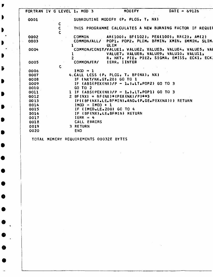
FORTRAN IV G LEVEL 1, MaO 3 MOOI FY DATE = 69126
0001
0002 0003
0004
0005
0006 0007 0008 0009 0010 0011 0012 0013 0014 0015 0016 0017 0018 0019 0020
C C C
C
SUBROUTINE MOOIFY (P, PLCG, T, NX'
THIS PROGRAMME CALCUlATES A NEW BURNING FACTOR IF REQUIF
COMMON AR(100), BF(102), PEX(lOO), RR(2), AH(2' COMMON/All/ POP1, POPZ, PLIH, BFMIN, XMIN, EMMIN, SLIM 1
1 QLIM COMMON/CONST/VAlUE1, VALUEZ, VAlUE3, VALUE4, VALUE5, VAl
1 VALUE7, VAlUE8, VALUE9, VALU10, VALUlI, 2 R, NXT, PIE, PIEZ, SIGMA, EMISS, ECK1, ECK;
COMMON/ER/ IERRt lINTER
IMOO = 1 4~CAlL LCSS (P, PlOG, T, Bf(NX), NX)
IF (NXT/NX.GT.20' GO Ta 1 IF (ABS(PEX(NX)/P - 1.t.lT.POPZ' GO TO 3 GO TO 2
1 IF (ABS(PEX(NXt/P - l.).lT.POPI' GO TO 3 Z BF(NX' = BFCNX'*(PEXCNX,/P'**3
if«8FtNX).LE.BFMIN'.AND.CP.GE.PEXCNX')) RETURN IMOO = IMOO + 1 IF (IMOO.LE.200' GO TO 4 IF (BFCNX).lE.BFMIN' RETURN IERR = 4 CAlL ERRORS
3\ RETURN END
TOTAL MEMCRY REQUIREMENTS 00032E BYTES

69126 19/31/45
JR IF REQUIREO.
2), AHe 2' EMHIN, SlIM. HIlIH,
VALUES. VAlUE6, VAlUll,
, ECKl, ECK2, ECK3
URN
PAGE 0001
--------------- McGILl UNIVERSITY COMPUTINGCENTRE ---~

..
• • ...
fORTRAN IV G LEVEl l, MOD 3 PRINTO DATE :; 69126
0001
0002
0003 0004 0005 0006 0007 0008 0009 0010 0011 0012 0013 0014 0015 0016 0011
0018 0019 0020 0021 0022 0023 0024 0025 0026 0027
0028 002g 0030 0031
SUBROUTINE PRINTO (NX.P,PT,RHO,T,TT,TW,H,V,AM,GM,CP,DSTAI C C PRINTO A SUBROU1INE TO PRINT OUT THE DATA CALCUlATED. C THE DATA IS PRINTEO IN SINGLE SPACED BLOCKS OF FIVE AND C PROVISION IS MADE TO PRINT .. EVERY S.TATION OR ANY DESIRED Ii C WITH OR WITHOUT.THE FIRST STATION. C
COMMON/PRT/ NlINE, NPAGE, NPl, NPCT, NPRINT C C THIS SELECTS THE STATIONS FOR WHICH RESULTS ARE PRINTED.
GO TO (103,104,105,106), NPRINT 104 If(NPCT.EQ.2) GO Ta 109 107 NPCT =~PCT + 1
If(NX.~E.I) GO Ta 108 IFCNP1.EQ.I) GO Ta 103 GO TO 108
109 NP CT = 1 GO TO 103
105 If(NPCT.EQ.IO. GO TO 109 GO TO 107
106 IF(NPCT.EQ.20i GO TO 109 GO TO 107
102 NPAGE = NPAGE + 1 WRITE(6,4' NPAGE
4 FORMAT (1H1, 120X, SHPAGE , 12/1H , 2X, 2HNX, SX, IHP, 6) 1 7X, 3HRHO, 8X, 2HTS i 6X, 2HTT, 6X, 2HTW, 7X, IHH 1
2 7X, IH~t 7X, 2HGM, 6X, 2HCP, 5X, 5HOSTAR, 7X, 2H( 3 2HQW/IH , IX, 3HSTN, 3X, SHPRESS, IX, 9HTOT PRES~
4 7HDENSITY, SX, 4HTEMP, 2X, 8HTOT TEMP, lX, 6HWALl 5 8HENTHALPY, lX, 1HF S VEL, IX, 7HMACH NO, 2X, 5H( 6 2X, 7HSPEC HT, 2X, 6HDELTA*, 4X, 8HFRN COEF, 4X, 7 IH , SX, 8HLB/SQ FT, IX, 8HLB/SQ FT, lX, 8HlB/CU 8 5HOEG R, 3X, 5HOEG R, 3X, 5HOEG Rf 3X, 6HBTU/LB, 9 6HFT/SEC, 49X, 6HLB/SEC/lH ,
NL INE = 8 NBLOCK = 5
103 IF (NLINE.GE.56) GO TO 102 IF(NBLOCK.lT.S} GO TO 101 WRITE (6,6'
6 FORMAT (lH » NLINE = NLINE + 1 NBLOCK = 0
101 WRITE(6,5'NX,P,PT,RHO,T,TT,TW,H,V,AM,GM,CP,OSTAR,CF,QW 5 FORMAT(lH ,I4,F8.1,F8.0,E12.4,3F8.0,F8.l,F8.0,2F8.3,F8.4 1)'
NBLOCK = NBLOCK + 1 NLINE = NLINE + 1
108 RETURN END
TOTAL MEMCRY REQUIREMENTS 00067C BYTES

:; 69126
CALCUlATED. OF FIVE AND
19/31/45
ANY DESIRED INCREMENT
IT
1 ARE PR INTED.
~X, 5X, IHP, bX, 2HPT, 2HTW, 7X, IHH, 1X, IHV,
rtOSTAR, 7X, 2HCf, 9X, lX, 9HTOT PRESS, lX, EMP, lX, 6HWALL T, lX, ~CH NO, 2X, 5HGAMMA, HFRN COEF, 4X, 6HTRANSPI T, lX, 8HlB/CU fT, 3X,
3X, 6HBTU/LB, 2X,
,OSTAR,CF,QW 8.0,2F8.3,F8.4,3(2X,E9.4
PAGE 0001
---------------- McGlll UNIVERSITY COMPUTlNGCENTRE -----'
• • • ;. • " • • • • • • • • • • • • • • • • • Allo.
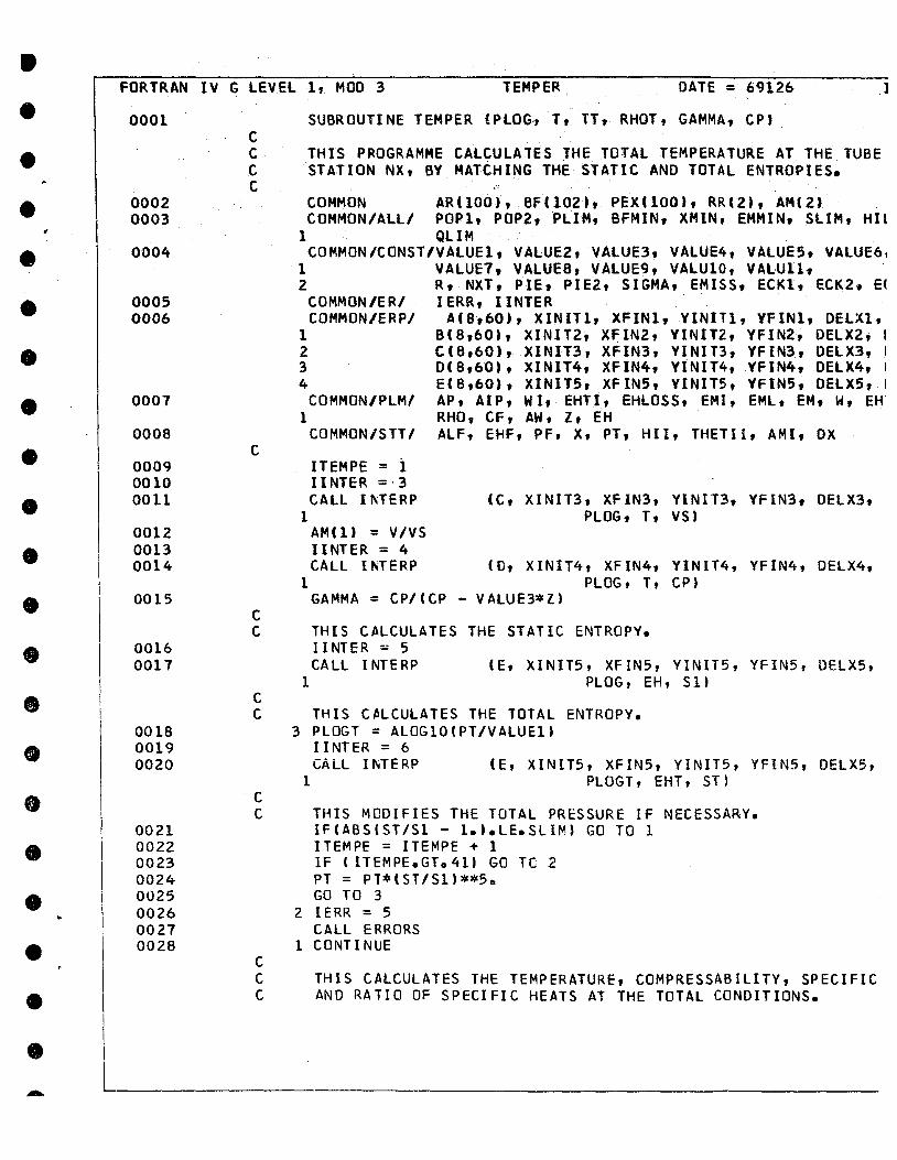
FORTRAN IV G LEVEl l, MOD 3 TEMPER DATE = 69126 .1
0001
0002 0003
0004
0005 0006
0007
0008
0009 0010 0011
0012 0013 0014
0015
0016 0017
C C C C
C
C C
C
SUBROUTINE TEMPER (PlOG, Tt TT, RHOT, GAMMA, CP,
THIS PROGRAMME CAlCULA1ES THE TOTAL TEMPERATURE AT TH~ TUBE STATION NX, BY MATtHING THE STATIC AND TOTAL ENTROPIES.
COMMON ARlIOO), BF(102 •• PEXlIOOt, RR(2t, AM(2. COMMON/AlLI POP1, POP2, PlIM, BFMIN, XMIN, EMMIN, SlIH,HIl
1 QLIM . COMMON/CONST/VAlUEl, VAlUE2, VAlUE3, VAlUE4, VALUES. VAlUE6,
1 VALUE1, VALUES, VAlUE9, VAlUIO, VALUll~ 2 R, NXT, PIE, PIE2, SIGMA, EMISS, ECKl, ECK2, EC
COMMON/ERI IERR, lINTER COMMON/ERP/ A'8,60), XINIT1, XFIN1,YINIT1, YFINl, DElXl,
1 S(S,60), XINIT2, XFIN2, YINIT2, YFIN2~ DElX2, 1 2 C(S,60), XINIT3, XFIN3, YINIT3, YFIN3, OElX3, 1
3 D(S,60), XINIT4, XfIN4, YINIT4, YfIN4,OElX4, 1
4 E(S,60), XINIT5, XFINS, YINIT5, YFIN5, OElX5, !
COMMON/PlMI AP, AIP, WI, EHTI, EHlOSS, EMI, EMl, EM, H, EH 1 RHO, Cf, AW, Z, EH
COMMON/STTI AlF, EHF, PF, X, PT, HII, THETII, AMI, OX
ITEMPE = i lINTER =·3 CAll 1 ~TERP (C, XINIT3, XFIN3, YINIT3, YFIN3, OELX3,
1 PlOG, T, VS) AM(I) = V/VS lINTER = 4 CALl 1 NTERP (0, XINIT4, XFIN4, YINIT4, YFIN4, DELX4,
1 PLOG, T, CP) GAMMA = CPI (CP - V ALUE3*Z)
THIS CALCULATES THE STATIC ENTROPY. Il NTER ::: 5 CALL 1 NTE RP 'E, XINIT5, XFIN5, YINIT5, YFIN5, OELX5,
1 PLOG, EH, SU
C THIS C~LCULATES THE TOTAL ENTROPY. 0018 3 PLOGT = ALOGIO'PT/VALUEl) 0019 liNTER = 6 0020 CÂLL INTERP (E, XINIT5, XFIN5, YINIT5, YFIN5, DELX5,
0021 0022 0023 0024 0025 0026 0027 0028
C C
C
1 PLOGT, EHT, ST)
THIS MODIFIES THE TOTAL PRESSURE IF NECESSARY. IF(ABS(ST/Sl - 1.).LE.SLIM) GO TO l ITEMPE = ITEMPE + 1 IF (ITEMPE.GT.41) GO TC 2 PT = PT*(ST/S1'**5o GO TO 3
2 IERR = 5 CALL ERRORS
1 CONTINUE
C THIS CAlCULATES THE TEMPERATURE, COMPRESSABILITY, SPECIFIC C AND RATIO OF SPECIFIC HEATS AT THE TOTAL CONDITIONS.

THE. TUBE IlES.
19/31/45
2. SlIH,HIlIM,
;, VAlUE6, l, , ECK2, ECK3
l, DElXl, DElYl, , DElX2, DElY2, , OElX3, DElY3, , .DElX4, DELY4, • DElX5, DElY5 :M, W, EHT, V,
, DX
, DElX3, OELY3,
, DELX4, OElY4,
, OELX5, DELY5,
l, DELX5, OEL Y5,
SPECIFIe HEAT, "Js.
PAGE 0001
------------ Mc G 1 L L UNI VER S 1 T Y COMPUTING CENTRE ___ .....J
• • • • • • • • • • • • ., • ., • • • • • • •
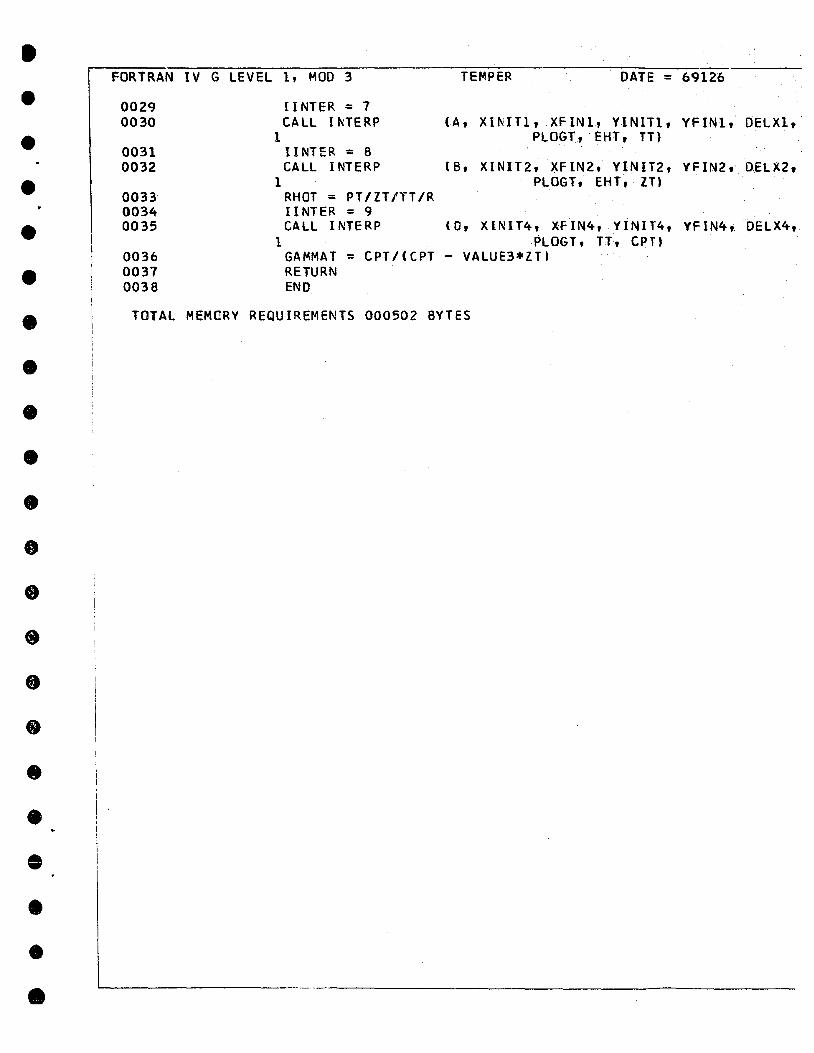
FORTRAN IV G LEVEL 1, MOD 3
002<) 0030
0031 0032
0033 0034 0035
II NTER :: 7 CALL 1 ~TERP
1
1
lINTER = 8 CALL 1 NTERP
RHOT :: PT/ZT/TT/R lINTER = 9 CALL INTERP
TEMPER DATE = 6<)126
( A, X 1 fil 1 Tl, X FIN l, Y l N Il l, Y FIN 1" 0 EL Xl t PLOGT, EHT. TT)
( B , X 1 NIT 2 , X FIN 2 , YI N lT 2 , V FIN 2, O.E L X 2 t PLOGT, EHT ,Zll
(D, XINIT4, XFIN4, YINIT4, YFIN4, DELX4, PLOGT, TT, CPTt
0036 0037 0038
1 GAMMAT RETURN
= CPT/(ePT - VALUE3*ZTt
END
TOTALMEMGRV REQUIREMENTS 000502 BYTES

19/31/45. PAGE 0002
l, DELX1, DELY1,
2, D.ELX2, DEL'f2,
4, DElX4, DELY4,
------------- McGILL UNIVERSITY COMPUT/NG CENTRE ~
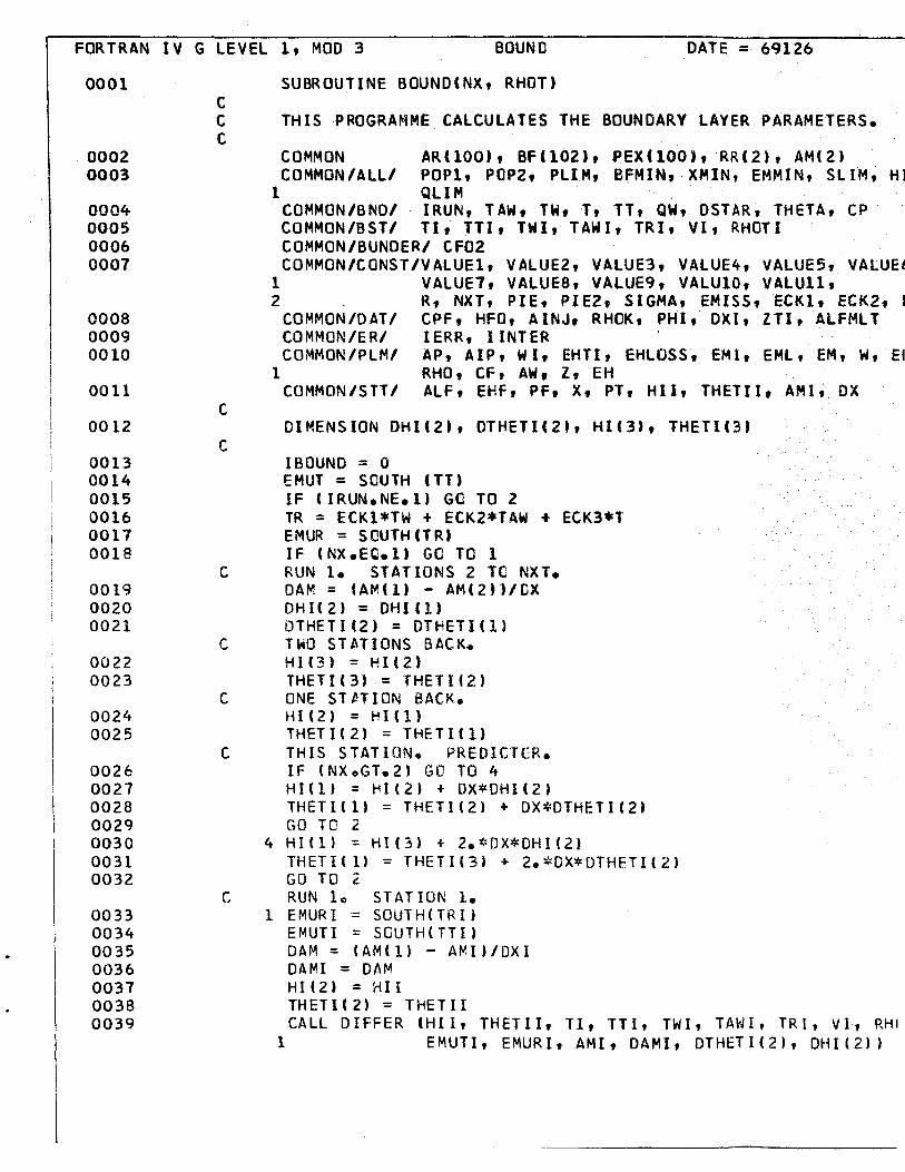
FORTRAN IV G lEVEl l, MOD 3 BOUND DATE = 69126
0001
0002 0003
0004 0005 0006 0007
0008 0009 0010
0011
001Z
0013 0014 0015 0016 0011 0018
0019 OOZO 0021
0022 0023
0024 0025
0026 0027 0028 0029 0030 0031 0032
0033 0034 0035 0036 0037 0038 0039
C C C
C
c
c
c
c
c
c
SUBROUTINE BOUNDCNX, RHOT'
THIS PROGRAMME CAlCUlA1ES THE BOUNOARY lAYER PARAMETERS.
COMMON ARCIOO), BF(I02), PEX(lOO),RRCl), AMe2' COMMON/All/ paPI, POP2, PlIM, BfMIN,.XMIN, EMMIN,SlIM., Hl
1 QllM . (OMMON/BND/ IRUN, TAW, TW, T~ TT, QW, DSTAR, THETA, CP COMMON/BST/ TI, TTI, TWI, TAWI, TRI, VI~ RHOTI COMMON/BUNDER/ CFOl COMMON/CONST/VAlUE1, VAlUEZ, VALUE3, VAlUE4, VAlUE5, VALUE~
1 VAlUE7, VAlUE8, VAlUE9, VAlUI0, VAlUll, 2 R, NXT, PIE, PIE2, SIGMA, EMISS, ECKl, ECKl, 1
COMMON/DAT/ CPF, HFO, AINJ. RHOK, PHI, DXI, lTI, AlFMlT COMMON/ERI IERR, lINTER COMMON/PlMI AP, AIP, WI, EHTI, EHLOSS, EMI, EMlt EH, W. El
1 RHO, CF, AW. l, EH COMMON/STT/ AlF, EHF, PF, X, PT, Hll, THETII, AMI, OX
DIMENSION DHI(Z), DTHETICZt, HIC3', THETIC3.
IBOUND = 0 EMUT = SOUTH (TT' IF (IRUN.NE.I) GO TO 2 TR = ECKl*TW + ECKZ*TAW + ECK3*T EMUR = SOUTH CT lU IF (NX.EC.la GO TO 1 RUN 1. STATIONS l Ta NXT. DAM = (AM(I' - AM(2'1/OX DHI(2) = DH!(!) DTHETI(Z) = DTHEll(l) TWO STATIONS BACK. Hl(3) = HUZl THETI(3) = THElI(2' ONE ST~TION BACK. HU2l = HI(!' THETI(Z) = THElICl} THIS STATION. PREDICTCR. IF (NX.GT.Z' GO TO 4 HI(l' = HI(2' + OX*OHI(2) THETIC1' = THETI(Z) + DX*OTHETI(Z) GO TO 2
4 H!(l) = HI(3) + Z.*OX*OHI(Z' THET!( l' = THETI(3} + 2.*OX*OTHETI(2' GO TO 2 RUN 10 STATION 1.
1 EMURI = SOUTH(TRI) EMUTI = SGUTH(TTI' DAM = (AM(l) - AMI)/OXI DAMI = DAM HUZ' = :.-ill THETI(2) = THETII CALL DIFFER CHIl, THETII, TI, TTI, nn, TAWI, TRI, VI. RH'
1 EMUTI, EMURI, AMI, DAMI, DTHET1(2), DHI(Z')

6 19/31/45
METERS.
Me2' ,SLIM" HIlIM,
TA, CP
lES, VALUE6, Ill, :1, ECK2, ECK.3
AlFMlT
, EM, W. EHT, V,
Ut OX
~It VI. RHOTI, , OH 1 ( 2) )
PAGE 0001 , 1
------------- Mc G 1 L L UNI VER S 1 T Y COMPUT/Ne; CENTRE ----'

! 1
1
1
1
1
1 i 1 l
!
FORTRAN IV G LEVEL l, MOO 3 BOUND
0040 0041
C PREOICiOR. FIRST STATION. HI(1) = HI(2) + OX*OHI(2) THETI(l) = THETI(2) + OX*OTHETI(2)
C ALL STATIONS. ALL RUNS.
DATE = 69126 19/31/45
0042 2 CALL OIFFER CHI(1), THETI(1),T, TT, TW, TAW, TR, V, RHOT, EMUT,
0043 0044
0045 0046 0047 0048 0049 0050 0051
0052 0053 0054 0055 0056 0051 0058
1 EMUR, AM(1), DAM, OTHETI(l), OHIC1') HIX = 11I( lt THETIX : THETlel'
C CORRECTOR. HIC1' = HI(2' + OX/2.*eOHIC1' + OHI(2» THETICl) = THETIC2' + OX/2.*COTHETIC1' + DTHETI(2») lFCABSC1.- HlCl'/HIX).lE.HILIM' GO Ta 3 lBüüNû = IBOUND + 1 IF (IBOUND.LT.IOO' GO TO 2 IERR = 6 CALL ERRORS
C CALCULATE OUTPUT QUANTITIES. 3 CF = C F02*2.
THETA = TT*TT*TT/T/T/T*THETI(l) HC = T~/T*HI(l) + TAW/T - 1. OSTAR = HC*THET A QW = CF02*RHO*V RETURN END
TOTAL MEMCRY REQUIREMENTS 000582 BYTES
69126 19/31/45
, TR, V, RHOT, EMUT, HU.
tET I( 2) )
PAGE 0002
---------------- McGILL UNIVERSITY COIrIPUTINGCENTRE --_ .......

,
•
• • • • • • • • • • • • •
FORTRAN IV G LEVEL l, MOO 3 01 FFER OATE = 69126
0001
0002 0003
C C C
C
SUBROUTI NE OIFFER (HI , THET 1 , T ,TT , TW 1 TR, V , RHOT ,EMUT ,EMUR 2 DAM , OTHETl, DHI.
THIS'SUBROUTINE CONTAINS THE BOUNOARY LAYER EQUATIONS.
COMMO~/BUNDERI CF02 COMMON/ER/ IERR, lINTER
IF (HI.GT •• 7' GO TO 1 IERR = 14 CALL ERRORS
1 HOM = 1.535*(HI - .1J**(-2.115. + 3.3 IF (HD~.GE.3.) GO TO 2 IERR = 15 CALL ERRCRS
2 F = .0306*(HOM - 3.0.**(-.653. 3 HC = (TW*HI + TAW'/T - 1. 4 HTR = T/TT*(HC + 1 •• - 1.
IF (V.lE.O.) GO TO 9 IF (THETI.LE.O.J GO TO 9 IF (RHOT.LE.O.) GO TO 9 IF (EMUT.GT.O.) GO TO 5
9 1 ERR = 16 CALl ERRORS
, ,
0004 0005 0006 0007 OOOS 0009 0010 0011 0012 0013 0014 0015 0016 0017 001S 0019 0020 5 CF02 = .123*(V*THETI*RHOT/EMUT)**(~.26S)*T/TR*(TR/TT)**~ 0021 0022 0023
0024 0025
1 *«TT + 19S.)/(TR + 19S."**C.26S'/EXP(1.56*HI' 6 OXOX = T/TR*T*T*T/TT/Ti/Ti*(EMUR/EMUT'**(.268J 1 OTHETI = CF02*T*T*T/TT/TT/TT - THETI/AM*OAM*(2. + HTR) 8 OHI = -(HI - .7'**3.715/417.*(F*DXOX/THETI - HOM/AM*OAM
1 - HOM/THETI*OTHETI) RETURN END
TOTAL MEMCRV REQUIREMENTS 0005EC BYTES

9126
, TW , EMUR
UATIONS.
19/31/45
,TAW , ,AM ,
~(TR/TT) ** (.402) ll.56*HI' 1 ~. + HTR) ~DM/AM*DAM
PAGE 0001
-------------- McGILL U.,.IVERSITY COMPUTINGCENTRE ___ --.J
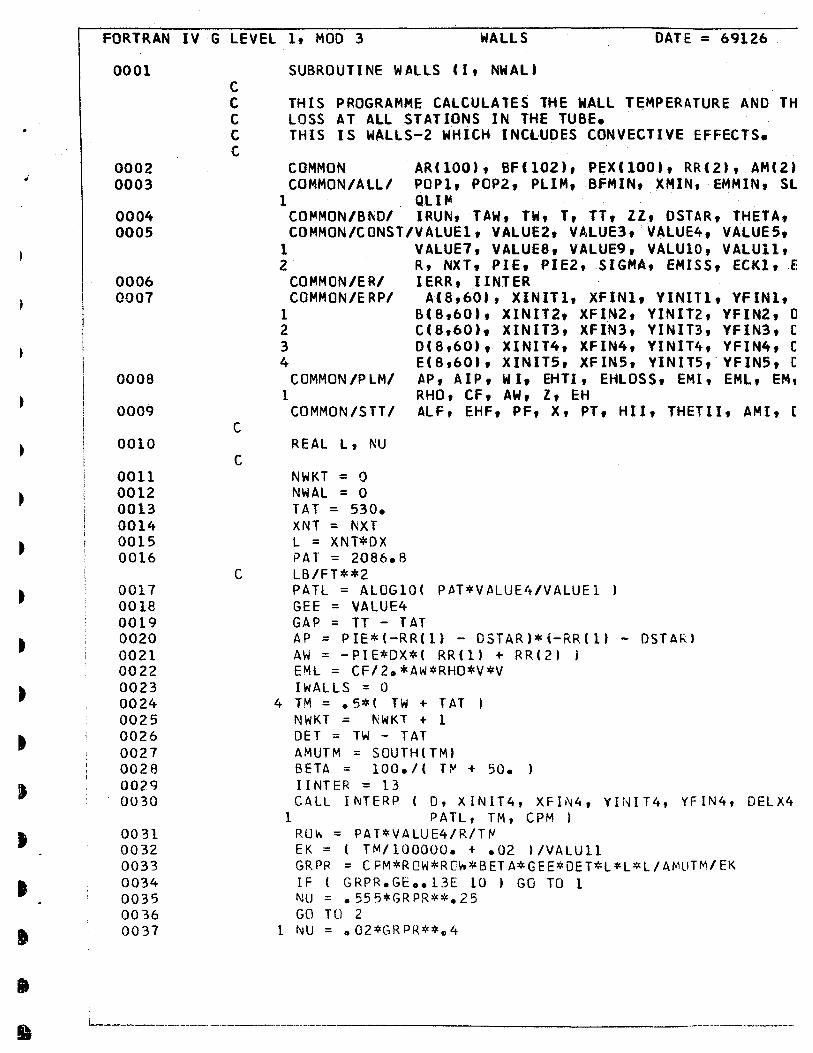
•
FORTRAN IV G LEVEL l, MOO 3 WAllS DATE = 69126
0001
0002 0003
0004 0005
0006 0007
OOOS
0009
0010
0011 0012 0013 0014 0015 0016
0017 0018 0019 0020 0021 0022 0023 0024 0025 0026 0027 0028 0029 0030
0031 0032 0033 0034 0035 0036 0037
C C C C C
C
C
C
SUBROUTINE WALlS CI, NWAl'
THIS PROGRAMME CALCUlATES THE WALL TEMPERATURE AND TH LOSS AT AlL STATIONS IN THE TUBE. ' THIS IS WALLS-2 WHICH INCLUOES CONVECTIVE EFFECTS.
COMMON ARCIOO), BFC10Z), PEXI100., RRI2', AMCZ. COMMON/ALL/ POP1, POP2, PlIM, BFMIN, XMIN, EMMIN, Sl
1 Qllf04 COf04MON/B~O/ IRUN, TAW, TW, T, TT, Zl, OSTAR, THETA, COMMON/CONST/VALUE1, VALUE2,VAlUE3, VALUE4, V~lUE5,
1 VALUE7, VALUES, VAlUE9, VAlU10, VALUl1, 2 R, NXT, PIE, PIE2, SIGMA, EMISS, ECK1,E
COMMON/ER/ IERR, liNTER COMMON/ERP/ AIS,60', XINIT1, XFIN1, YINIT1, YFIN1,
1 8(S,60), XINIT2, XFIN2, YINIT2, YFINZ, 0 2 C(S,60), XINIT3, XFIN3, YINIT3, YFIN3, ~ 3 0(S,60', XINIT4, XFIN4, YINIT4, YFIN4, C 4 E(S,60', XINIT5, XFIN5, YINIT5,'YFIN5, C
COMMON/PlM/ AP, AIP, WI, EHTI, EHLOSS, EMI, EML, EM. 1 RHO, CF, AW, l, EH
COMMON/STT/ AlF, EHF, PF, X, PT, HII, THETII, AMI, [
REAL L, NU
NWKT -= 0 NWAL = 0 TAT = 530. XNT = NXT L = XNT*DX PAT = 2086.8 LB/FT**2 PATL = ALOGIO( PAT*VALUE4/VALUE1 , GEE = VAlUE4 GAP = TT - TAT AP = PIE*(-RRll) - DSTAR1*(-RR(l' - DSTARI AW = -PIE*OX*( RR(l' + RR(21 j
EML = CF/2.*AW*RHO*V*V Ir~AL LS = 0
4 TM = .5*( TW + TAT NwKT = t\WKT +- l DET = TW - TAT AMUTM = SOUTH(TMI BETA = 100./( H' + 50. ) II NT ER = 13 CALL II\JTERP ( D, XINIT4, XFIN4, YINIT4, YFIN4, DELX4
1 PATL, TM, CPM ) RO~ = PAT*VALUE4/R/T~ EK = ( TM/IOOOOO. + .02 '/VALUll GRPR = CFM*ROW*RCh*BETA*GEE*DET*L*L*L/AMUTM/EK IF ( GRPR.GE •• 13E 10 1 GO TD l NU = .555*GRPR**.25 GO TO 2
l NU = o02*GRPR**o4
L ___ ._>, _______ ., __ ------------------ -----.. _._-_._.-

69126 19/31/45
RE AND THE ENTHALPY
FECTS.
2), AM(2. EMMIN, SLIM, HILIM,
:, T.HETA, CP VALUES, VALUE6, VALUll,
;, ECKl ,E:CK2, EC K3
., YFINl, DELXl, DELY1, YFIN2, DELX2, DELY2,
, YFIN3, DELX3, DELY3, , YFIN4, DELX4, DELY4, ,. YFIN5, DELX5, DELY5 ~ EML. EM, W, EHT, V,
[l, AMI, DX
N4, DELX4, DELY4,
tEK
PAGE 0001
-------------------- McGILL UNIVERSITY
1
C,,"PUTING CENTRE ~

FORTRAN IV G LEVEL 1, MOO 3 WAlLS DATE = 69126 19/3
0038 2 CONTINUE 0039 QC : EI<*NU/L*DET 0040 QR = E~ISS*SIGMA*( TW**4 - TAT**4 '/VALUll 0041 QSUM = QC + QR 0042 tAU = CF*RHO*V*V/2. 0043 EMUS = SOUTH 1 T) 0044 EKB = 1 T/100000. + .02 )/3600. 0045 PRTS ~ CP*EMUB/EKB 0046 QW = CP*TAU*( TT- TW )/PRTB/V 0047 IF ( ABSIQW/QSUM - 1.).LE.QlIM ) GO TO 3 0048 IF ( NkKT.GE.51 » GO TO 5 0049 TW = TW*( QW/QSUM '**.25 0050 GO TO 4 0051 5 IERR = 7 0052 CALL ERRORS 0053 3 EHLOSS = QSUM*AW/W/AP 0054 RETURN 0055 END
TOTAL MEMORY REQUIREMENTS 000506 BYTES
! ,-------_ .. _-.-...... __ ._ .. _-

l26 19/31/45 PAGE 0002
.-.... ---.----.----- --....... --.--.. - .. ------- Mc G 1 L L U /III VER S 1 T Y COMPUTING CENTRE _J

.\
• • • • • • • • • • • •
FORTRAN IV G LEVEL 1, MOO 3 INTERP DATE = 69126
0001
0002
0003
0004 0005 0006 0001 0008 0009 0010 0011 0012 0013 0014 0015 0016 0011 0018 0019 0020 0021 0022 0023 0024 0025 0026
0027 0028 0029
C C C
C
C
SUBROUTINE INTERP lA, XINIT , XFIN , YINIT , YFIN , DElX 1 X, y, l'
THIS SUBROUTINE INTERPOlATES IN THE DATA TABLES.
COMMON/ER/ 1 ERR, 1 INTER
DIMENSION AC8,60.
IERR = 0 IF lX.LT.XINIT' IERR ; 10 IF (X.GT.XFIN' IERR = Il IF (Y.LT.YINIT' IERR = 12 IF CY.GT.YFIN) IERR = 13 IF (IERR.NE.O) CAll ERRORS Il = lX - XINrT./DElX JI = (y - YINIT)/DElY
·1 = 11+ 1 J = JI + 1 IF(AlI ,J '.EQ.O.' IERR = 9 IF (AlI+l,J).EQ.O.) IERR = 9 IF(AlI ,J+l'.EQ.O.' IERR = 9 IFCA(I+l,J+l'.EQ.O.' IERR = 9 IF (IERR.NE.O' CAll ERRORS EII = Il EJI = JI DX = X - XINIT -EII*OElX DY = DELY - (y - YINIT - EJI*DELY) Cl = DX*DY/DElX/DELY C2 = DX/DELX C3 = DY/DELY Z = A ( l, J+ 1 ) * ( 1. - C 2 - C3 + Cl) + A ( 1 + l, J+ 1 , *(
1 + A ( l, J ) * ( C3 - Cl + A' 1 + l, J ) *c 1 Il NTER = 0 RETURN END
TOTAL MEMCPY REQUIREMENTS 0005C8 BYTES
... ",' .- ............. - ... -"'.~._-_._---------- ---

126 19/31/45 PAGE 0001
IN , DElX , DElY ,
•
, J+l ,*( C2 - CU
-------------- Mc G 1 L L UNI VER S 1 T Y COMPUTING CENTRE ----'

FORTRAN IV G LEVEL l, MOD 3 SOUTe; DATE = 69126 19
0001 FUNCTICN SOUTHeT) C C THIS FUNCTION EVALUATES THE VISCOSITY USING SUTHERlANO'S LAW. C
0002 COMMON/CONST/VALUE1, VALUE2, VALUE3, VALUE4, VALUES, VAlUE6, 1 VALUE1, VALUES, VAlUE9, VAlU10, VAlU1l, 2 R, NXT, PIE, PIE2, SIGMA, EMISS, ECKl, ECK2, ECK
C
• 0003 0004
SOUTH = T**1.5 *VALUE6/tT + 198.) RETURN
0005 END
• TOTAL MEMORY REQUIREMENTS 00015C BYTES
• • • • • • • • • • • • e
• • ..

= 69126 19/31/45 PAGE 0001
G SUTHERlANO'S LAW.
4, VALUES, VAlUE6, 0, VAlUl1, SS, ECKl, ECK2, ECK3
--- Mc G 1 L' L U toi 1 VER SI T Y COMPUTING CENTRE ___ --1

• • • • • <1
• • • • • • • • • • • • • • '. • • • • 1_-
fORTRAN IV G lEVEL l, MOD 3 ERRORS DATE = 69126
0001 0002 0003 0004 0005 0006 0,007 0008 0009 0010 0011 0012 0013 0014 0015 0016 0017 0018 0019 0020 0021 0022 0023 0024 0025 0026 0027 0028 0029 0030 0031 0032 0033 0034 0035 0036 0037 0038 0039 0040 0041 0042 0043 0044 0045 0046 0047 0048 0049 0050 0051 0052 0053 0054
SUBROUTINE ERRORS COMMCN/E~/IERR, lINTER WRITE (6. 100)
100 FÛKMÂï (iH , 2X, '**ERROR**') GO Ta (1,2,3,4,5,6,7,8,9,10.11.12,13,14,15,16,17,18,19',
1 WRITE (6,101' GO TO 200
2 WRITE (6,102' GO TO 200
3 WRITE (6,103, GO TO 200
4 WRITE (6,104' GO TO 200
5 WRITE (6,105' GO TO 200
6·WRITE (6,106' GO TO 200
7 WRITE (6,107' GO TO 200
8 WRITE (6,108' GO TO 200
9 WRITE (6,109' GO TO 201
1û ~RITE (6,110) GO TO 201
Il WR 1 T E (6,111' GO Ta 201
12 WR.n E ( 6 , 112 ) GO TO 201
13 WR 1 T E ( 6 , 113 ) GO TO 201
14 WRITE (6,114' GO TO 200
15 WRITE (6,108) GO TO 200
16 WRITE (6,116' GO TO 200
17 WR 1 TE (6, 117 , GO TO 200
18 WR Il E ( 6 , 118 , GO TO 200
19 WRITE (6,119' 200 RETURN 201 GO TO (302,302,303,303,303,303,303,303,303,301,301,301, 301 WRITE (6,351' 1 INTER
GO TO 200 302 WRITE (6,352' 1 INTER
GO TO 200 303 WRITE (6,353' 1 INTER
GO TO 200 304 WRITE (6,354' lINTER
GO TO 200 101 FORMAT (lH , 'I~AGINARY SQUARE ROOT OBTAINEO') 102 FORMAT (lH , 'EXCESSIVE ITERATION IN SUBROUTINE *PRESS'

1<1/31/45 PAGE 0001
L8,19', IERR
Ol,301,304"IINTER
*PRESS*' »
------------ Mc G 1 L L UNI VER S 1 T Y COMPUTING CENTRE ___ ...J

,
• • • • • • • • • • • •
FORTRAN IV G LEVEt l, MOD 3 ERRORS DATE =69126
0055 0056 00,57 0058 0059 0060
0061 0062 0063 0064 0065 0066 0067 0068 0069 0070 0071 0072 0073 0074 0075
TOTAL MEMORY
103 FORMAT (lH , 'EXCESSIVE ITERATION IN SUBROUTI~E *LOSS*" 104 FORMAT (lH • 'EXCESSIVE ITERATION IN SUBROUTINE *MOOIFV* 105 FÙRMAT (lH t'EXCESSIVE ITERATION IN SUBROUTINE *TEMPER* 106 FORMAT 1lH .·~XCESSIVE ITERATION IN SUBROUTINE *BOU~D*' 107 FORMAT (lH ,'EXCESSIVE ITERATION INSUBROUTINE *WALLS*t 108 FORMAT ClH t 'IN',SUBROUTI NE *ERRORS* INVALIOERROR MESSA
ID' ) . ., '" 109 FORMAT (lH , 'ZERO VALUE'FOUND IN TABLES') 110 FORMAT (lH , 'INTE~POLAllo~ ERR OR. *x*ioo LOW.') 111 FORMAT (lH , • INTERPOLAT'ION ERROR. ,*X* TOO HIGH." 112 FORMAT (lH t 'IN;ERPOLATION ERROR.*V* TOO LOW." 113 FORMAT (1H , 'INTERPOLATION ERROR. *V* TOO HIGH." 114 FORMAT (lH , 'ERROR IN *OIFFER* HI LES~ "THAN.7') 116 FORMAT (lH , 'ERROR IN *OIFFER* ILLEGAL NEGATIVE PARAMEl 117 FORMAT (lH , 'OVERRUN AT NEXT STATION') 118 FORMAT (lH , 'EXCESSIVE ITERATION FOR TW IN *MAIN*') 119 FORMAT (lH , 'UNABLE TO CALCULATE --HS--I) 351 FORMAT {1H , 'CALL NO.' 13, • LOCATED IN MAIN') 352 FO RMAT (lH , 'CAlL NO.I 13, ' LOCATED IN PRESS t ,
353 FORMAT (lH 'CAlL Ne.' 13, ' LOCAl ED IN TEMPER') 354 FORMAT (1H , 'CALl NO.' 13, ' LOCATED IN WALLS"
END
REQUIREMENTS 00090E BYTES
._---_ .... --_._-_._.
.6
:LOSS*' 1 :MOOIFV.' » :TEMPER*' ) iBOUNO*' ) =WALLS*')
19/31/45
IR MESSAGE SELECTE
1
1 •
1 1 ,
1 PARAMETER' ,
~*' )
PAGE 0002
------·-------McGILL UNIVERSITY COMPUT'NG CENTRE ~

• • • • • • • • • • • • • • .' • • •
FORTRAN IV G lEVEL l, MOO 3 VALUES DATE ='69126
0001
0002
0003
0004
0005
0006
0001 0008
0009 0010 0011
0012
0013
0014
0015
0016
0017
0018
0019
0020
0021
0022
C C C C
C
C C
C
C
C
C C C C C C C C C
C C
C
C
c
c
c
c
c
c
c
SUBROUTINE VALUES
THE NUMERICAl VALUES OF VARIOUS CONSTANTS REQUIREO IN 1
PYRO ARE CONTAINEO HERE.
COMMON/CONST/VALUE1, VAlUE2,' VAlUE3, VALUE4, VALUES, VI 1 VALUE7, VALUE8, VA,"-UE9,VAlUIO, VAlU11, 2 R, NXT, PIE, PIE2, SIGMA, EMISS. ECK1" ECI
COMMON/PRTI NlINE, NPAGE, NP1, NPCl, NPRINT
R -= 1719. CFT.**2'/CSEC.**2'*(OEG.R.l NXT IS REAO IN. TK = 533.2 DEG.R. EMUK = .00001226 LB./FT.-SEC. PIE = 3.1415«;21 PIE2 = 6.2831853 SIGMA AND EMISS ARE OBlAINEO FROM SUBROUTINE DATA. EC 1<1 = .5 ECK2 = .22 ECK3 = .28 FACTORS FOR ECKERT'S REFERENCE TEMPERATURE. NPRINT IS REAO IN. 1 PRINT EVERY ·STATION. 2 PRINT EVERY SECOND STATION. 3 PRINT EVERY TENTH STATION. 4 PRINT EVERY TWENTITH STATION. NPl IS READ IN. 1 TO PRINT FIRST STATION IN TUBE. o TO SUPPRESS PRINTING OF FIRST STATION. NPCT = 1 STARTING VALUE FOR PRINT COUNTER.
VAlUE1 = 68059.593 CONVERTS POUNDALS/SQ. FT. TO ATMOSPHERES. VAlUE2 = 50060.814 CONVERSION FROM FT.-POUNDAlS TO BTU'S*2. VALUE3 = .06868 GAS CGNSTANT R IN BTU/LB.-DEG.R. VAlUE4 ::: 32.114 CONVERTS LBS. Ta POUNDALS. VALUES = .8879 FACTOR FOR T AW. VALUE6 = (TI< + 198.'*EMUK/TK**1.5 CONSTANT FOR SUTHERLANO'S LAW. VALUE7 = 1.01 INITIAL l ASSUMED IN MAI~ PRoGRAMM~. VALUE8 = .5 INITIAL WALL TEMPERATURE IS ASSUMED Ta BE VALUE8*TOTAI VALUE9 = 459.76 CONVERTS OEGREES FARENHEIT Ta DEGREES RANKINE. VALU10 = 32.
26 19/31/45
ED IN PROGRAMME
UE5, VALUE6, .U11, ,Ki., ECK2, ECK3
8*TOTAl TEMPERATURE
PAGE 0001
----.--------- McGILL UNIVERSITY COMPUTINGCENTRE --_ ......

FORTRAN IV G lEVEL 1. MOD 3 VALUES DATE = 69126 l
C REFERENCE TEMPERATURE FOR ENTHALPIES. 0023 VAlUll = 3600.
C CONVER1S HOURS TO SECONDS. 0024 RETURN 0025 END
TOTAL MEMORY REQUIREMENTS 000232 BYTES

19/31/45 PAGE 0002
------------- Mc G 1 L L U HI VER SI T Y COMPUTING CENTRE ___ ....l

• • • • • • • • • • • 1
FORTRAN IV G LEVEL 1, MOD 3 FIRE DATE :: 69126
0001 0002 0003 0004 0005 0006 0007 0008 0009 0010 0011
0012
0013
0014 0015 0016 0017
0018 0019 0020 0021 0022 0023
0024 0025 0026 0027 0028
SUBROUTINE FIRE (IF, FUEL, RHOK, ALFMLT, EHF, T, TF' REAL Kf:RO, NUN DIMENSION FUEL(3' DATA KERO, NUN, SHEL/4HKERO, 4HNONE, 4HSHELI IF ( FUEL(l •• EQ.KERO , GO TO 1 IF ( FUEL(l'.EQ.NUN , GO TO 3
'IF (FUELt1 •• EQ.SHEL) GO TO 5 IERR = 30 CALL ERRORS
1 IF ( IF.EQ.2) GO TO 2 IF = 2
C FUEL KEROSINE RH OK :: 50.835
C FUEL DENSITY IN LBS.ICU. FT. ALFMLT = 1326.26
C CONVERTS FUEL-AIR RATIO TO PERCENT STOICHIGMETRIC. 2 EHF = 17784.5 - ( T - 2000. '*0.19833 + 0.47*( TF - 537.
RETURN 3 IF ( IF.EQ.2 , GO TO 4
IF = 2 C NO FUEL.
RHOK == O. ALFMlT = O.
4 EHF :: O. RETURN
5 IF (IF.EQ.2' GO TO 6 IF = 2
C FUEL S~ELLDYNE RHOK = 83.372 - .0287* TF ALFMLT = 1360.54
6 EHF :: 17085. - .755*(T - 2000.' + TF*.231 + TF*TF*.2093E RETURN END
TOTAL MEMCRY REQUIREMENTS 000354 BYTES
L ______ ~ ______ --

~126 19/31/45 PAGE 0001
r, TF'
rue. TF - 537.)
*TF*.2093E-03
-------------- McGlll UNIVERSITY COMPUTINGCENTRE ----'
• • • 1
• • • • • • • •
FORTRAN IV G LEVEL1, MOD 3 DATA DATE ::: 69126
0001
0002
0003
0004
0005
0006
0007 0008
0009 0010
C C C
C
C
C
C
C
SUBROUTINE DAT A
THE VALUES OF SOME INPUT DATA ARE CONTAINEO HERE.
COMMON/CONST/VALUEl, VALUE2, VALUE3, VALUE4, VALUES, VALt 1 VALUE7, VALUES, VALUE9, VALUlO, VALUll, 2 R, NXT, PIE, PIE2, SIGMA, EMISS, ECKl, ECK2
COMMON/DATI CPF, HfQ, AINJ, RHOK, PHI. OXI, lTI, ALFMLT·
AINJ = .lOSOE-OS INJECTCR AREA IN SQ. FT. PHI = O. INJECTION ANGLE IN RADIANS. SIGMA = .1714E-OS STEFAN-BOLTlMAN CONSTANT IN BTU/HR.-SQ. FT.-(OEG.R.'**4 EMISS = 0.2 DXI = cOS INITIAL SUBDIVISION. RETURN END
TOTAL MEMORY REQUIREMENTS 00013E BYTES

19/31/45
i, VALUE6, L, , ECK2, ECK3 ~LFML T·
• '**4
PAGE 0001
------------ Mc G 1 L L UNI VER S 1 T Y COMPUTING CENTRE ___ ....J

FORTRAN IV G LEVEL 1, MOD 3 SMOT DATE = 69126
0001 0002 0003
0004 0005 0006 0001 0008 0009 0010 0011 0012 0013 0014 0015 0016 0011 0018 0019 Q020 0021 0022 0023 0024 0025 0026
SUBROUTINE SMOT (ALF) COMMON ARCIOO), BFCI02), PEX(IOO), RR(2), AM(2' COMMON/CONST/VALUE1, VALUE2, VALUE3, VALUE4, VALUES, VALI
l 'VALUE1, VALUE8, VALU~9, VALUIO, VALUll, 2 R, NT, PIE, PIE2, SIGMA, EMISS, ECK1,.ECK2
SIGM = O. DIMENSION STG(3' STGC2' = BF(l. STG(3) = BF( 1) ôr(iOl) = BF(lOO) BF(102) = BF(lOO' 00 3N=I,NT STG(I) = STG(2) STG(2' = STG(3' STG(3) = BF(N) BF(N) = (SIG(l) + STG(2' + STG(3) + BFCN+l' + BFIN+2' '1 SIGM = SIGM + BF(N)
3 CONTINUE D04N=I,NT BFIN' = BFCN'/SIGM
4 CONTI NUE WRITE (7,2' BF
2 FORMAT (10F8.5) ALF = ALF*SIGM*.8S WRITE (7,1' ALF
1 FORMAT ('ALF = l, ElO.5' RETURN END
TOTAL MEMG~Y REQUIREMENTS 00021e BYTES

19/31/45
VALUE6,
CK2, ECK3
) /5.
PAGE 0001
----------- Mc G 1 L L U H 1 VER S 1 T Y COMPUTING CENTRE - __ ....1

FORTRAN IV G LEVEl 1. MOD 3 LIMITS DATE = 69126 19
0001 SUBROUTINE LIMITS 0002 COMMON/ALLI POP1, POP2, PLI M, BFMIN, XMIN, EMMIN, SLIM, HILl
1 QLIM C MAIN
0003 PLIM. = .03 C MAIN, MOOIFY
0004 POPI = .02 0005 POP2 = .01 0006 BFMIN = .001
C PRESS 0001 XMIN = .005
C LOSS 0008 EMMIN = .005
C TEMPER 0009 SLIM = .0005
C BOLIND 0010 HI LI M = .00001
C WALLS 0011 QLIM = .0005 0012 RE1URN 0013 END
TOTAL MEMORY REQUIREMENTS 000166 BYTES

19/31/45 PAGE 0001
lM, HILIM,
Mc G 1 L L UNI VER S 1 T Y COMPUTING CENTRE ---.......