abstract - fdot.gov reports... · abstract the report presents ... a launching gantry was used at...
TRANSCRIPT


ABSTRACT
The report presents the comprehensive instrumentation program for the Sunshine Skyway
Bridge, Florida, which has been carried out to monitor the bridge behavior during and after
construction. The program includes the physical measurements of concrete compressive
strength, modulus of elasticity, Poisson's ratio, coefficient of thermal expansion, shrinkage,
creep, concrete strains, vertical deflections, and temperature distributions at selected
locations of the Sunshine Skyway Bridge. A comparative study of the measured time
dependent strains of a typical pylon and segments of the bridge and the corresponding
analytical predicted values are presented in references 1 and 2.

BACKGROUND Cable stayed bridge technology has been used extensively only in the past two decades. Maximum clear span for cable stayed concrete bridges has expanded to over 1400 feet. Generally, the concrete end steel bridges compete with each other in long span crossings. For the application of a cable stayed concept to long span concrete bridges, instrumentation of actual structures provides a solid data base for verification of design assumptions and future developments of innovative concepts. The Sunshine Skyway Bridge is currently the longest clear span concrete bridge built in North America. A single plane of cable-stays makes this bridge to be unique for its size. Fig. and Muller Engineers, Inc. designed this bridge for the Florida Department of Transportation (FDOT) based on the European developed cable-stayed technology. The Sunshine Skyway portion of US 19 begins at Maximo Point at the Southern tip of the Pinellas County peninsula and extends southward crossing lower Tampa Bay and its 500 foot wide main shipping channel in Hillsborough County and connects with U.S 41 north of Palmetto in Manatee County, a length of about 15 miles. This bridge is a part of inter-state highway 275, connecting St. Petersburg and Bradenton as shown in Fig. 1 and is located 1000 feet east of the existing bridge structure with a total length of 21,878 feet (4.14 miles). The bridge consists of four different types of spans trestle approach spans, low level approach spans, high level approach spans and three cable-stayed spans. Standard prestressed I-girders are used for 128 spans accounting for 13,018 feet in the trestle approach spans. Twin box girders are used for the low level approach spans for a length of 4860 feet of the Skyway bridge. High level approach spans are made up of a large single cell box girder carrying both north and south bound traffic. The span lengths of the high level approach spans vary from 140 feet to 240 feet with a total length of 1720 feet. The cable-stayed spans consist of two 540 feet side spans and a 1200 feet main span. Fig, 2 shows an elevation of the high-level approach spans and the main cable-stayed spans. A single plane of cables distributed in a fan-type arrangement support the main cable-stayed span. Vertical clearance of the bridge super-structure at the main pier support is 175, feet above sea-level. A total of 21 cable stays for each half of the main span are supported on reinforced concrete pylons reaching 431 feet above sea-level. The pylons are supported by two main piers each consisting of twin-pier shafts.
2

3

4

The main cable-stayed span, consists of 96 single-cell precast box segments. An isometric view of a typical mid-span segment is shown in Fig. 3. Each box segment has approximate dimensions of 14'-8", 94’-5" and 12'-0" in depth, width and length respectively. Bridge segments were made in a single cast at a speed of one a day making the pre-cast unit one of the largest single-cast concrete segment weighing approximately 170 tons. Bridge segments with cable-stay anchorage vary slightly to accommodate stay forces and anchorages. The cables were anchored along the center line of the box section. The objective of this, paper is to present the development of a comprehensive instrumentation program for the physical measurements of concrete compressive strength, modulus of elasticity, Poisson's ratio, co-efficient of thermal expansion, shrinkage, creep, concrete strains, vertical deflections and temperature distributions at selected locations of the Sunshine Skyway Bridge. A comparison of the measured and analytical time dependent strains of a typical pylon and segments of the bridge are presented in references 1 and 2. CONSTRUCTION METHODS The construction methods used were different for the approach spans and the main span. The span-by-span construction method was used for the twin-box girders in the low-level approach spans. Precast box segments of one whole span were assembled at the precasting yard on a steel platform. A launching gantry was used at the bridge site to lift the whole pre-assembled box-girder span into place. At the high level approach spans the balanced cantilever method was used for the single cell box-girders. Balanced cantilever erection of the bridge segment was achieved using a launching girder. The pre-cast concrete segment was transported from the pre-casting plant at Port Manatee, Florida, to the bridge site by barges, and then hoisted in place hydraulically. The balanced cantilever method was also used for the main cable-stayed spans. The precast segments were transported to the bridge site by barge and then lifted by a jacking device at the end of the cantilever. TESTS ON CONCRETE USED IN TYPICAL BRIDGE SEGMENT Properties of concrete in the segments, P3N1N and P3N10N in the high level approach span and segments PIN1S and P1N5S, PlN25S and PIN48S in the main cable-stayed span, were determined using standard 6 X 12 inches concrete cylinders. All the concrete
6

6

cylinders were made alongside each selected bridge segment thereby representing actual material used in the bridge segments. LABORATORY TESTS The tests included measurements of short and long-term material properties on a total of 24, 6 x 12 inch concrete cylinders for each, bridge segment. All the cylinders were shipped to the Construction Technology Laboratories (CTL) after the age of approximately 1 to days and upon arrival at CTL, the cylinder molds were stripped and the cylinders stored at a constant temperature of 73° F and 50% relative humidity (RH). Short-term Property Tests These tests included measurements of concrete compressive strength, modulus of elasticity, Poisson's ratio and co-efficient of thermal expansion. The tests were performed, in conformance with ASTM designation: C 469-83 (Ref. 3), C 39-81 (Ref. 4) and Corps of Engineers, U.S Army CRD-C 39-81 Procedures: (Ref. 5). Tests were conducted at approximate concrete ages of 3, 7, 28, 90, 180 and 365 days. Tables 1-6 show the summary of the measured concrete properties for the six selected instrumented segments. The actual concrete ages of specimens at time of testing are given in the tables together with, the casting dates of the bridge segments. The design compressive strength of concrete for the bridge super-structure at 28 days was 5500 psi.
8

8

Long-term Property Tests Time dependent shrinkage measurements of concrete specimens were made starting from the age of three days whereas the creep tests were initiated at concrete ages of approximately 28 days. All the creep tests were conducted in conformance with ASTM designation C 512-83 (Ref. 6). External mechanical strain gages were used to measure long-term concrete movements between two target points. The target points were glued on to the surface of the concrete
10

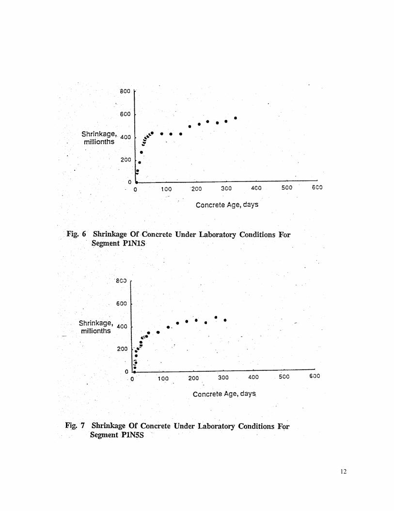
immediately after stripping of cylinder molds. The average longitudinal concrete movements are obtained as the average of the three readings from the mechanical strain gages across the target points. Corresponding to each set of the shrinkage measurements, a set of creep readings was taken and the creep strains are determined from subtracting the shrinkage measurements from those of the concrete cylinders at a given stress level. Figs. 4 - 8 show the measured shrinkage of concrete for the segments P3NIN, P3N10N, PIN1S, P1N5S and PlN25S versus concrete ages. Specific creep is defined as the amount of concrete creep per unit stress. The specific creep of concrete for segments P3N1N, P3N10N, P1N1S P1N5S and PlN25S versus concrete age is shown in Figs. 9 - 13 respectively. FIELD TESTS Creep and shrinkage properties of concrete have been shown to exhibit different behavior under indoor and outdoor conditions (Refs. 7, 8, 9). Therefore, shrinkage and creep tests conforming to ASTM designation C 512-83 (Ref. 6) were conducted on concrete from bridge segments P3N1N, P3N10N, PlN1S, PIN5S, PlN25S and PIN48S under outdoor conditions in St. Petersburg, Florida. Vibrating wire-gage and mechanical strain meter were used in strain measurements. The vibrating wire-gages were of type VCE 4200 and positioned at the center of the cylinders before casting. The two readings recorded from each vibrating wire-gage represented internal concrete temperatures and longitudinal concrete movements since the initial reading at the location of the sensor. The mechanical strain measuring device was used to obtain the longitudinal concrete surface movements between the two target points on the cylinder from the initial reading. Air temperature, relative humidity and concrete surface temperature of the cylinders were also recorded whenever the concrete strains were measured. In addition, shrinkage measurements were made whenever a set of creep readings were taken. Creep strains were obtained by subtracting the shrinkage measurements from the readings of the concrete cylinders at a given stress level. Typical concrete shrinkage measured by the external mechanical strain meters and internal vibrating wire-gages are shown in Figs. 14 and 15 for the segments P3N1N and P1N1S. The specific creep of concrete was also measured using both the external mechanical strain meters and internal vibrating wire-gages. Figs. 16 and 17 show the specific creep of concrete for typical segments P3N1N and P1N1S respectively. Different sets of points in the figures represent specific creep of concrete loaded at different concrete ages. It is
10

11
12

13

14

15

16

17

observed that specific creep of concrete becomes smaller when age of concrete at loading is larger. Figs. 18 and 19 show the specific creep of the concrete loaded under different concrete ages for segments P3NIN and PlN1S respectively. FIELD INSTRUMENTATION A total of 17 precast bridge segments, 3 pylon sections and 11, sections of two main piers were selected for instrumentation. Table 7 gives a summary of the instrumentation of the selected bridge components (Figs. 20, 21 and 22). The three pylon sections were located at 8 feet, 85 feet and 145 feet above the pylon base of pier PIN. Instrumented pier sections were located at 1’- 6" and 38' above the impact slab. Three sections were instrumented below the impact slab of piers PIN and PIS besides a pier section at 8 feet below roadway of pier PIN. Monitoring bridge behavior included measurements of longitudinal concrete strains, concrete temperatures and vertical bridge deflections. Concrete Strain Measurements Sensors must be capable of providing consistent and stable readings for a long period of time to enable long term concrete strain measurements. Carlson strain meters of type A-10 with 4-wire conductor cable was therefore used with a gage length of 10 inches. The two readings provided by each Carlson strain meter represent concrete strain and temperature at the location of the strain meter. A total of 232 Carlson strain meters were used with 159 strain meters for the 17 bridge segments, 17 strain meters for the three pylon sections and 56 strain meters for the 11 pier sections. Locations of Strain Meters The strain meters were installed horizontally to measure longitudinal movements along the main bridge axis. The detailed locations of the installed Carlson's strain meters in a typical bridge segment are shown in Fig. 23. Fig. 24 shows the general locations of the meters in the three pylon sections. All the strain meters were positioned vertically to measure variations of vertical concrete movements of the pylon with time. Carlson strain meters were embedded in concrete by placement inside the segment before concrete casting. Bridge segments were precast units manufactured at the precasting plant in Port Manatee, whereas the pylon sections, however were cast-in-place units. Carlson strain meters were installed at the bridge site in the three pylon sections and the pier section, 8 feet below
18

19

20

21

22

23

roadway. Carlson strain lead wires for the pylon sections were routed to the pylon base of pier FIN through a 3 inch diameter conduit. The conduit was installed in every section of the pylon up to 145 feet above the pylon base.
25

Temperature Measurements Selected bridge segments P3NIN, P3N19N, PIN1S, P1NSN, PIN25S and PIN48S were instrumented with 28 thermocouples for monitoring temperature effects on the bridge superstructure. Thermocouples were divided into seven groups, each with four thermocouples. The temperature distribution was measured through the depth of the concrete slab of the box section. Fig. 25 shows the distribution of the seven thermocouple groups around a bridge segment. Temperature distributions across the major and minor axes of the pylon sections were measured using 14 thermocouples (Type T). The distribution of the thermocouples at the pylon section 85 feet above the pylon base is shown in Fig. 26. Thermocouples were embedded in concrete before concrete casting, ensuring proper placement across the concrete slabs. Extension wires of the thermocouples attached to the underside of the reinforcement cage were bundled up and taken out of the bridge segment concrete at the same location as the Carlson strain lead wires. Data Acquisition System And Measured Data Readings from the installed sensors were measured either manually or electronically. A computer-controlled automatic data acquisition system (ADAS) developed at the Construction Technology Laboratories (CTL) was used to acquire the data. Readings taken manually before the installation of ADAS on site included all Carlson strain readings and temperature and outdoor concrete creep and shrinkage data. With the large .number of installed sensors, an automatic data acquisition system was used for data scanning and recording. Sensors were connected to dedicated signal processors for scanning. The scanned readings were transmitted to a master unit via standard data communication serial link. The master signal processor was controlled by an on-site micro-computer which can address each and every signal processor. Upon receiving the readings in the controlling micro-computer, data were stored on the magnetic cartridge. Fig. 27 presents a schematic illustration of how the ADAS functions. The measured strain data represent movements of concrete per unit length along the longitudinal axis of the strain meter. All strain readings were adjusted to a reference temperature of 73°°F for comparison purposes based on the assumption that thermal
26

26

27

28

movements were totally unrestrained. Compressive strains were measured at different concrete ages fo r bridge segments, pylon sections, piers and foundations sections. DISCUSSIONS AND CONCLUSIONS The instrumentation for the Sunshine Skyway Bridge has been carried out to monitor the bridge behavior during and after construction. The determination of properties o f concrete from typical bridge segments, modulus of elasticity, Poisson's ratio, coefficients of thermal expansion, shrinkage and creep was made based on tests conducted under both laboratory and outdoor conditions. Details of instrumentations for concrete strains, vertical deflections and temperature distributions at selected typical locations of the Sunshine Skyway Bridge together with an automatic data acquisition system (ADAS) are presented and the evaluation, analysis and comparison of the data with the predicted theoretical values would be discussed in a subsequent presentation following this publication.
29

REFERENCES: 1 . Shahawy, M.A., "Comparison Of The Analytical And Measured Time-Dependent Strains In The Pylon Of The Sunshine Skyway Bridge;" Research Report No. SRR 02-92, Florida Department of Transportation, January, 1992. 2. Shahawy, M.A., "Comparison Of The Analytical And Measured Time-Dependent Strains In The Segments Of The Sunshine Skyway Bridge;" Research Report No. SRR 03-92, Florida Department of Transportation, Currently Under Review And Expected To Be Published In March, 1992. 3. Standard Test Method for Static Modulus of Elasticity and Poisson's Ratio of Concrete in Compression; ASTM C 469-83, American Society for Testing and Materials, Philadelphia, Pennsylvania, 1983. 4. Standard Test Method fo r Compressive Strength of Cylindrical Concrete Specimens, ASTM C 39-81, American Society for Testing and Materials, Philadelphia, Pennsylvania, 1981. 5. Method of Test for Coefficient of Linear Thermal Expansion of Concrete, CRD-C 39-81, Corps of Engineers, U.S. Army, Handbook for Concrete and Cement, 1981. 6. Standard Method of Test for Creep of Concrete in Compression, ASTM C 512-83, American Society for Testing and Materials, Philadelphia, Pennsylvania, 1983. 7. Shin, K.N., Daniel, J.I., and Russell, H.G., “Time Dependent Behavior of Segmental Cantilever Concrete Bridges,” Report to the State of Illinois, Department of Transportation, submitted by Construction Technology Laboratories, Skokie, Illinois, March 1983, 101 pp. 8 . Sh i n , K.N. and Russell, H.G, Discussion of "Creep of Concrete in Variable Environments," by W .L. Gamble, Journal of the Structural Division, American Society of Civil Engineers, Vol. 109; No . 11, November 1983, pp. 2751-2753. 9. Gamble, W.L., "Creep of Concrete in Variable Environments," Journal of the Structural Division; American Society of Civil Engineers, October 1982, pp. 2211-2223. 10. Shin, K.N., Overman, TR. and Reichenbach, "Instrumentation and Analysis Services for the Sunshine Skyway Bridge, Phase I - Part B, and Phase II - Part A," Interim Report, Construction Technology Laboratories, Inc., January 1987.
31