abstract fcsi. or chromite, 1 charge c hrome furnaces u...
TRANSCRIPT
The Proceedings of INFACON 8
Development of an Operator Guidance System for Intermediate Carbon Charge Chromium Production
Louis M. Booysen*, Lloyd R. Nelson**, K. Narayana Swamy** and Marius Visser*
*Ferrometals , Samancor Ltd. Private Bag X7228 , Witbank, 1035 , South Africa
**Chromium R&D Department, Billiton Process Research Private Bag XlOO 14, Randburg , 2125, South Africa
ABSTRACT
Development of an Operator Guidance System (OGS) to control
a 30 t Creusot-Loire-Uddeholm (CLU) converter, located on the
Ferrometals Plant of Samancor, for production of Intermediate
Carbon Charge Chromium (IC3) is described. The process
involves bottom injection of oxygen and steam , to effect
decarburisation (De-C) of feed charge chromium (ChCr)
containing greater than 6% C to produce IC3 of between 1-4 '7c
C content.
The OGS is based upon a phenomenological heat and kinetic
mass transfer model, which takes into account the transitory gas
bubble/slag/metal and permanent contact top slag/metal
reactions. The capability of the model to predict key converter
performance parameters (C content , temperature and Cr
recovery to alloy) is demonstrated through comparison with
actual plant operating data. Application of the OGS to
dynamically recommend suitable gas injection rates and coolant
additions to effect control of the commercial converter operation
is presented.
INTRODUCTION
IC3 containing 1-4% Chas been produced commercially since
1986 and involves the staged batch oxygen refining or li4uid
ChCr analysing 5-8% C, <6 % Si and 50-55 'k Cr in a 30 t CLU
converter (Figure 1). Despite substantial improvements made to
the production of IC3 in the CLU converter at Ferromctals over
the past dccadc'-'J, the need was identified for even tighter
metallurgical process control to further:
• increase productivity and effective plant capacity
• lower cost of production through enhanced process efficiency
• improve product 4uality
• increase the range of marketabk product grades .
To effect such improvements , an OGS has bi:en developed to
control the CLU converter. The most critical stage. from a
control perspective , is the De-C stage which yields the final IC3
product. The OGS has primarily been focused on this De-C
stage . The OGS has the capability of predicting the likely
performance of the batch process through some future time.
based on prevailing process conditions. Once accepted in the
plant environment , the OGS will ultimately be upgraded to
deliver dynamic control over the CLU converter process.
1 FcSi. or chromite,
Liquid C h<ir ~ & basic fluxes
Charge C hrome Furnaces u Cr,~;.:ich···· ·· ·· Reduction/Refining Stage
: .......- -.............. T a pping ICJ ":l ~hsic ~ lhslagging discard
produd /~ !luxes ~ ~lag'
• ---- + ------ \d ~ Decarburisation Stage
o, J1,o mixture
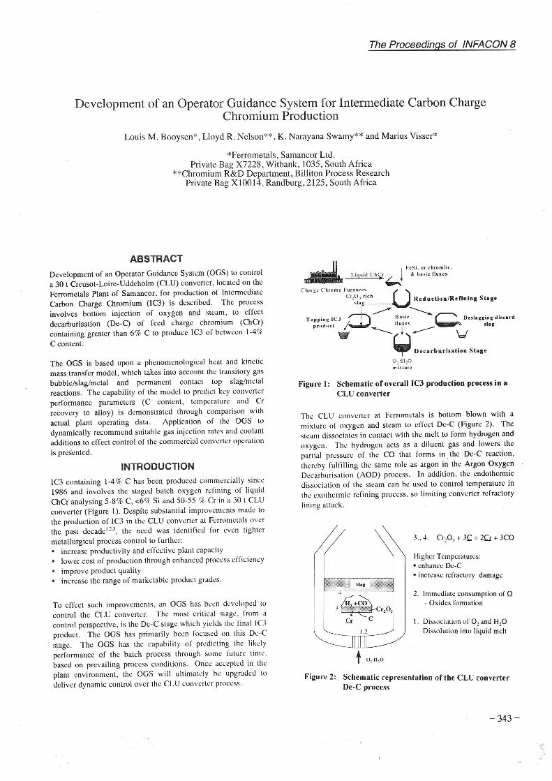
Figure I: Schematic of overall IC3 production process in a
CLU conve11er
The CLU converter at Ferromctals is bottom blown with a
mixture or oxygen and steam to effect De-C (Figure 2). The
steam dissociates in contact with the melt to form hydrogen and
oxygen. The hydrogen acts as a diluent gas and lowers the
partial pressure of the CO that forms in the De-C reaction,
thereby fulfilling the same role as argon in the Argon Oxygen
Decarbu~isation (AOD) process. In addition, the endothermic
dissociation of the steam can be used to control temperature in
the exothermic refining process. so limiting converter refractory
lining auack.
3 .. 4. Crz03 +JC= 2Q: + 3CO
Higher Tempcraturi:s: • enhance De-C • increase refractory damage
2. Immediate consumption of Q - Oxides fonnation
I. Dissociation of 0 2 and H20 Dissolution into li4uid melt
Figure 2: Schematic representation of the CLU converter De-C process
- 343.-

The Proceedings of INFACON 8
De-C Reactions of ChCr The two main sites at which refining reactions occur in the converter are:
1. Transitory reaction site
2. Permanent contact reaction site .
Transitory reaction site Transitory reactions refer to the reactions between the gas bubbles and the metal as the injected gases rise through the melt . As soon as the injected oxygen contacts the metal at the luyerc tip, it dissolves in the metal and reacts near instantaneously with elements dissolved in the metal bath . Due lo a high .local oxygen potential, the different elements that can be oxidised react in amounts roughly proportional to the atomic percentage of each element present in the melt. If only ·1hc dissolved Cand Cr arc considered, the following reactions occur al the luycre tip:
C+Q .CC+ xQ
=co (g) = CrOx (s,l)
where : x = 1 , 1 '/3 , 1 ~
(I)
For simplicity of illustration, x is chosen to be 1 '/,, so CrO, represents Cr,03 • As the slag-laden bubble rises through the metal, the Cr,03 contained reacts with the C in the metal according to:
Cr,03 (s) + 3C = 2Cr + 3CO(g)
In K
where : K T
Pea
= ln{ac,' Pco 3 I a,.,.,0 , a,.3}
= -84650/T + 54.63
=equilibrium constant = temperature . K = activity of Cr =partial pressure or co. atm
=activity of chromium oxide
= activity of C
(3)
(4)
From Equation (4) it can be seen that C oxidation according to Reaction (3) is favoured by a low ac, and a high a,. in the mctal. a high ac.p, activity, and a low Pea in the gas phase . From the
expression it is also clear that the extent of C oxidation is enhanced by a high tcmperatun: , but an upper limit is imposed on ii by the need lo ensure an acceptable extrnt or refractory wear.
For reasons of computational efficiency, the transitory slag is assumed to be Cr,0 3-saturated (i.e .. a,.,,0 , assumed to be unity)
in the OGS. Representation of the slag in this simplified manner has not been found lo introduce significant effect on OGS predictions.
Permanent contact reaction site Permanent contact reactions refer to the reactions occurring between the metal and the overlying top slag. The De-C reaction at this site is essentially due to Reaction (3). In the normal De-C stage of the converter. the slag is inore or less solid (referred to on the plant as a "dry .. slag). consisting of a molten slag phase saturated with chromium oxide and a solid chromium oxide-bearing phase.
-344-
REACTION KINETICS The specific rate controlling step in Dc-C is one of the following45
:
I . the !low of oxygen into the bath 2. the equilibrium given by Reaction (3) 3. mass-transfer of C from the bulk metal phase to the interface
A typical Dc-C profile reported on the plant for IC3 production' exhibits this classical kinetic behaviour (Figure 3) . The chemical reactions taking place -at the phase interfaces, at the high temperatures and relatively low pressures characteristic of pyrometallurgical processes, arc fast and so arc not normally rate-controlling.
() '----'--------'----~--~--~
4C 6D 80 100 12C Blowing time, min
Figure 3: A typical De-C profile with time
SI.AG IN
Ml :TA I. MIX
Figure 4: OGS representation in METSIM

DESCRIPTION OF MATHEMATICAL MODEL
The METSIM simulation software• has been used in the
construction of the multi-component, mass-transport based
kinetic model. A schematic of the METSIM 'CLU' model is
shown (Figure 4). Fundamentals behind this modelling
approach have been discussed elsewherc7.l! . Local chemical
equilibrium has been assumed to exist at each of the
metal/slag/gas interfaces.
The metal has been conceptually divided into three transitory
height steps. The Free Energy Minimiser (FEM) unit operations
1, 2 and 3 represent the transitory reaction of the metal with the
gas at the three height steps. The FEM is based on the
Solgasmix algorithm9 and computes the chemical equilibrium
state arising from the input elements under the prevailing
conditions of temperature and pressure (mid-height step
condition has been · assumed for the transitory reaction) . The
FEM unit -0peration 4 represents the permanent contact reaction
between the metal and the top liquid slag. The FEM unit
operation 5 represents the reaction between the top liquid and
solid slag.
Metal and slag phases have ' mass transfer' streams of bulk
composition and mass flowrates kAp leaving them and entering
the respective FEMs. Since the k of the gas is very high
compared to that of the metal, it is assumed that all the injected
gas substantially attains equilibrium with the mass transfer llow
of the metal al each height step. The input streams to the FEM
are brought into equilibrium and then arc split into phases ,
including any newly formed phases, such as solid or gas. The
slag and metal phases from the FEM arc returned to the bulk so
that the net rate of transfer for every species into the phase (W.
in units of kg/min) is given by the expression :
W = k'A 'p 'w, - kApwh (6)
where p, p'
w,
wb k, k' A,A'
= total mass concent ration (density) or the phase ,
kg/m 3
=mass fraction of a species at the surface , at
equilibrium =mass fraction of a species in the bulk
= mass transfer coefficient, m/min
= surface area between the phases . m'
= refers to the values in the stream coming out of
the FEM .
This expression therefore directly includes the effects of bulk
flow on the mass transfer rate and exactly describes the
condition of mass transfer control.
A user-friendly interface has been developed. The interface
allows the operator to change the compositions and temperature
of metal and slag, and the gas injection rates . The graphical
output screen shows the dynamic change in the C content.
temperature of metal , Carbon Removal Efficiency (CRE) ' . and
rate of C removal from the metal (dC/dt)'. The CRE and dC/dl
arc particularly important to distinguish lo permit the plant to
operate optimally under prevailing market conditions of reduced
and high IC3 alloy demand, respectively . Additionally, the
CRE is interpreted to be an effective instantaneous measure of
The Proceedings of JNFACON 8
Cr recovery to the alloy - important in view of the strong
influence of delivered ChCr on the overall cost of IC3
production. The operator can decide on corrective action to
maintain the CRE and/or the dC/dt a\ the highest l.evels possible
based on the predictions of the model , while still ensuring that
the desired alloy end poirit is achieved.
Thermodynamic Data and Solution Models Thermodynamic data from standard sources have been used for
all the components in the model. An Interaction Parameter
approach (involving Fc~, ivcnt-Cr-C-Si) has been used to
calculate the activity of species in the metal. A Regular
Solution model approach has been used to calculate the activity
of species in the liquid slag (involving Cr,03-Cr0-Fe0-Alp3-
Mg0-Ca0-Si0,).
Heat Loss Data
A heat balance trial was performed on the converter. Near the
end of a heat, when the temperature of the metal was around
1660°C, the metal was allowed to stand for a period of 40 minutes with injection of nitrogen through the bottom tuyeres at
a rate of 19 Nm3/min . The temperature of the outer shell of the
converter was measured using weld-patch thermocouples during
the trial period . Measurements of the temperature of the metal
were taken every 5 minutes using quick immersion
thermocouples. Metal samples were also taken during this time.
The temperature was used to calculate a constant heat loss term
of 0.36 °C/min for the converter for a given state of refractory
wear. This corresponds favourably with reported values of 1-3 °C/min on 45 to 100 t A0Ds51 o.11.1 o
Model Parameters
Permanent contact mass-transfer rates
The metal chemical analysis data of the heat balance trial were
used lo calculate the permanent contact mass-transfer rate of
metal. Since nitrogen was injected during the trial, all the C
removed from the metal during the trial must have been through
the pnmanent contact reaction between the metal and the top
slag. discounting any net reaction of the C with dissolved
oxygen in the metal. This gave a permanent contact metal
mass-transfer llow of 110 kg/min. On the assumption that the
mass transfer coefficient of slag is roughly half that of the metal
and that the density of slag is 3 .5 x 103 kg/m3, the top slag mass
transfer llow was estimated to be 29 kg/min.
Transitory reaction mass-transfer rates The precise value for the metal /gas interfacial area is not known
since it is highly dependent upon the size distribution and shapes
of the gas bubbles in the melt. Literature data" ·" ·13·1• on the
metal mass transfer coefficient also vary between 1-10 x 10·•
m/s. Because of these uncertainties, the transitory metal mass
transfer rate has been treated as an adjustable ' 'lumped"
parameter (kAp). A value of 2 .1x10 3 kg/min has been found
' CRL = the efficiency of utilization of oxygen in effecting De-C - a good
measure of process efficiency . 'dC.'dt = the instantaneous rate of change of C content in the alloy - a good
m c a~urc or productivity.
-345-
The Proceedings of INFACON 8
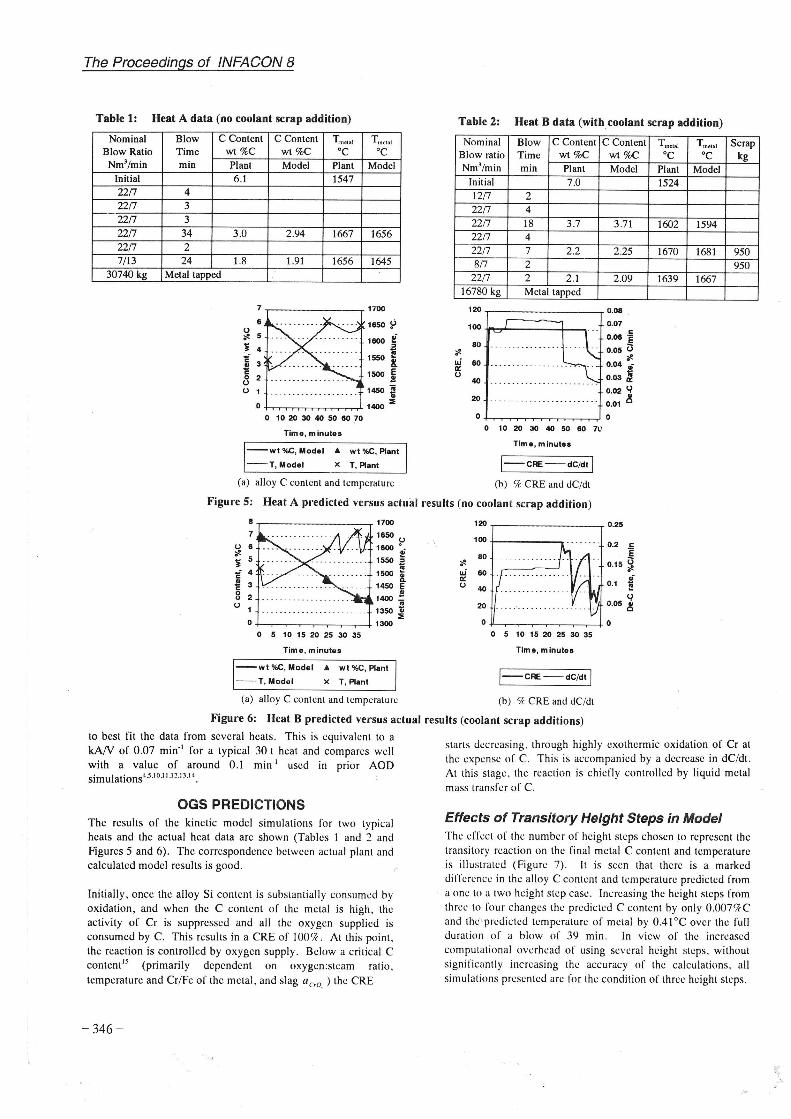
Table 1: Heat A data (no coolant scrap addition)
Nominal Blow Ratio
Nm3/min Initial 22!7 22{7
22!7 22{7 22{7
7/13 30740 kg
Blow C Content C Content Tmetal Trnw r.I
Time min
4 3 3
34 2
24 Metal tapped
wt %C Plant 6.1
3 .0
1.8
wt%C oc Model Plant
1547
2.94 1667
1.91 1656
O 10 20 30 40 50 ISO 70
Tim•, minutes
oc Model
1656
1645
--wt %C, Model & wt %C, Pl•nt
--T, Model X T, Plant
(a) alloy C content and temperature
Table 2: Heat B data (with coolant scrap addition)
Nominal Blow C Content C Content Blow ratio Time wt %C wt %C Nm3/min min Plant Model
Initial 7.0 12!7 2 22{7 4 22!7 18 3 .7 3.71 22!7 4 22{7 7 2.2 2 .25 8(7 2
22{7 2 2.1 2.09 16780 kg Metal tapped
120 ...--------~ O.OI
80
w ISO a: 0
40 . . . .. . . .. .... .. ...... .
20
0.07 c
o.oe e 0.05 0
"' 0.04 :-
0.03 ~ 0.02 ~ 0.01 ~
0+.....~~~~-----' 0 O 10 20 30 40 50 ISO 7L'
Time , minutes
1-cRE-dC/dt I (b) 'k CRE and dC/dt
Tmct11l Tmd111
oc oc Plant Model 1524
1602 1594
1670 1681
1639 1667
Scrap kg
950 950
Figure 5: Heat A predicted versus actual results (no coolant scrap addition)
0 5 10 15 20 25 30 35
Time, minutes
--wt %C, Model & wt %C, Plant
--T,Model x T, Plant
(a) alloy C content and temperature
80
w ISO a: 0 40
0.2 c . e
0.15 ~ .;
0.1 ~
~ 20 0 .05 ~
0-1'-~~-~~~~--+0 0 5 10 15 20 25 30 35
Time, minutes
1-cRE-dC/dt I (b) 'k CRE and dC/dt
Figure 6: Heat B predicted versus actual results (coolant scrap additions) to best fit the data from several heats . This is equivalent to a kAN of 0 .07 min·1 for a typical 30 t heat and compares well with a value of around 0 .1 min·1 used in prior AOD simulations•.s .1o.1 i .1".1 3 .1 •.
OGS PREDICTIONS The results of the kinetic model simulations for two typical heats and the actual heat data arc shown (Tables 1 · and 2 and Figures 5 and 6). The correspondence between actual plant and calculated model results is good.
Initially, once the alloy Si content is substantially consumed by oxidation, and when the C content of the metal is high , the activity of Cr is suppressed and all the oxygen supplied is consumed by C. This results in a CRE of 100%. At this point. the reaction is controlled by oxygen supply. Below a critical C content15 (primarily dependent on oxygen:steam ratio , temperature and Cr/Fe of the metal, and slag ac,o, ) the CRE
- 346 -
starts decreasing , through highly exothermic oxidation of Cr at the expense of C. This is accompanied by a decrease in dC/dt. At this stage , the reaction is chieOy controlled by liquid metal mass transfer of C.
Effects of Transitory Height Steps in Model The effect or the number of height steps chosen to represent the transitory reaction on the final metal C content and temperature is illustrated (Figure 7). It is seen that there is a marked difference in the alloy C content and temperature predicted from a one to a two height step case . Increasing the height steps from three to four changes the predicted C content by only 0 .007 'k C and the predicted temperature of metal by 0.41°C over the full duration of a blow of 39 min . In view of the increased computational overhead of using several height steps. without significantly increasing the accuracy of the calculations. all simulations presented arc for the condition of three height steps .

2.2 11170 0 0 ..... 1eea • ~ i 2.15 !! i 1866 ! --wt%C,end ~ 2.1 x. 0 111114 E --T.metal u .. 0 2.05
1M2 i ii c 1l ii: 2 1HO :I:
0 2 3 4
Transitory Height Steps
Figure 7:Variation of the predicted metal C content and temperature with number of transitory height steps
SENSITIVffY ANALYSIS
Sensitivity analyses were performed to determine the effects of key variables on the critical measured output variables, metal C content and temperature (Figures 8 and 9) . The sensitivities of input process and model variables arc shown . In the actual plant analysis , the process capability was additionally superimposed on the abscissa to permit the relative importance of the variables to be ranked. This allowed attention to be focused on the sequence of items to be tackled for de-bottlenecking the plant.
i g u 0 .E .. g' ..
.<= 0 .....
-30 -20 -10 0 10 20 30
%Change
-+-Initial wt %C -+-Metal mass --6-Scrapmasa --lf--02Aow --lf-- H20 flow
(a) Effect on final metal carbon content
The Proceedings of INFACON 8
Key Process Variables
Effects of gas flowrates A 1 % increase in the oxygen gas flowrate lowers the final C content by 0.5% (from 2.10 to 2.09 %C) and increases the final metal temperature by 0.15% (from 1592.7 to 1595.1 °C) . As would be expected from the fact that O, dissociates to 2Q, while H,O dissociates to Q (and H,), the effect of oxygen gas flowrate on the final metal C content is twice that of steam. The final metal temperature is raised by increasing the oxygen flowrate (exothermic refining reactions arc promoted) , while the effect of the steam flowrate is the inverse (the reaction of steam, including dissociation , is net endothermic).
Effects of initial C content A 1 %. error in the initial metal C content produces a predicted 2% error in the final C content and a predicted 0.28% error in the final temperature of metal. This emphasises the need for accurate measurement of initial ChCr C content on the plant.
s CJ ... ::i;: -c !! ·- " ~ I~ :; x. -" E 0 .. ';f!.. -
-30 -20 -10 0 10 20 30
%Change
--+-initial wt %C -+-Metal maaa --6-Scrapmaas --lf--02flow --lf--H20flow
(b) Effect on final metal temperature
Figure 8: Sensitivity analysis of process variables on process outputs
-30 -20 -10 0 10 20 30
%Change
--+-Heat loss ----Transitory Mass Transfer Rate ---+---Permanent Mass Transfer Rate
(a) Effect on final carbon content
.!: .. "' c
" .<= 0
';;'!. -30 -20 0 10 20
%Change
--+-Heat loss ------Transitory Maas Transfer Rate ___.,.._Permanent Mass Transfer Rate
(b) Effect on final metal temperature
Figure 9: Sensitivity analysis of some model variables on process outputs
30
-347 -

The Proceedings of INFACON 8
Effects of coolant scrap addition The effect of coolant scrap addition is dramatic if it causes the metal temperature to drop so low that it creates a condition where the metal C content falls below the critical C at which Cr oxidation over De-C becomes favourable . Notice how the CRE drops when excessive scrap additions arc made (Figure 6b). However, smaller scrap additions only have a marginal effect on the process (Figure 8).
Effects of Model Parameters The OGS model predictions on final metal C content and temperature arc shown to be relatively insensitive lo the three adjustable parameters of the model; namely , heal loss rate , permanent contact and transitory mass transfer parameters (Figure 9). Changes in the two former parameters in excess of 30% yield of the order of an 1 % change in the predicted final alloy stale in terms of C content and temperature . Changes in the transitory mass transfer parameter have slightly more marked effects - 30% change yields a maximum 4'k change in the final C content (from 1.94 to 1.86 %C).
PLANT IMPLICATIONS OF OGS Evaluation of the OGS predictions of just two actual plant De-C heats shows that there is considerable scope for improving the efficiency and consistency in the blowing cycle , particularly in terms of improved CRE and higher dC/dl. Specifically. an OGS should help to better, or al least emulate , the performance or the "best plant operator". This will accrue plant benefits due to shorter heats and less frequent overblowing of heats to achieve the desired C and temperature endpoints, directly leading lo operating cost savings in terms of:
• reduced losses of expensive Cr units to oxidation ;
• diminished converter refractory lining wear;
• decreased reactive gas consumption ;
• lowered rcductant (expensive ferrosilicon) and basic llux consumptions, and higher Cr recoveries in the subsequrnl reduction/refining stage .
Blowing Sequence and Control The CRE and dC/dt can be maintained at a high level throughout the blow by changing the total gas llowrate and the oxygcn:stcam ratio of the gas. The changes can be effected stepwise (i.e., blow at a set rate until a predetermined condition has been attained) or in a continuous fashion (to maintain the CRE and dC/dt at the optimum critical C set-point value permanently, as proposed by Szekely , et al.").
Recommendation of the optimum gas llowrates and scrap coolant additions in a stepwise approach is the goal of the initial on-line OGS. Later, it is hoped that a continuous blowing rate optimisation algorithm will be incorporated into a full control model, to optimise the CRE and dC/dt for the entire period of the blow based on the initial· conditions of the heal.
Top Lance The OGS predictions suggest that during the initial period of the blow dC/dt can be increased significantly. without compromising the CRE, by increasing the oxygen injection rate . This can be done to an extent by upgrading the existing bottom
-348 -
gas delivery system at the plant. Installation of a top injection lance is another option. The OGS can be readily modified to accommodate this latter condition, either by conceptually:
• "releasing" the injected gas at a predetermined bath depth as a function of top injection ratc16
• increasing the mass transfer rates as functions of top gas injection rate".
An additional benefit perceived for operation with a top lance in ChCr refining, is that a localised hot spot will dcvclopthcrmodynamically and kinetically favouring De-C relative to Cr oxidation.
Upgrade of Plant Instrumentation Sufficient and accurate instrumentation is a prcrcqutsttc for reliable OGS performance. A detailed evaluation of the capability of the process identified a significant deficiency regarding measurement of the Si content of the incoming ChCr. To address this shortcoming, a rapid solid-state Si sensor system was developed for on-line determination of the input ChCr Si content' ".
Other Less Tangible Benefits A number of other benefits can be auributcd to the joint OGS development program on the plant, but these arc difficult to quantify . Yet. distinct benefits have already been realised through the OGS development program due to the enhanced level of process understanding generated.
Specifically. a statistically significant improvement of 76 .6% in the mean converter refractory lining life was achieved, from a mean or 78 .7 heats in the period prior to the OGS project (but excluding the period of the first 28 campaigns when fettling was not practised'). to a mean of 139 heats since its inception in 1995 (Figure 10). This improvement can primarily be traced to selection of better rcfractorics for the converter lining and a proactive plant lluxing practice, but both developments were instigated following auditing or plant practice for the OGS.
CONCLUSIONS
An off-l ine OGS has been successfully developed to simulate production of IC3 on a 30 t CLU converter. The OGS has been shown to be capable of predicting plant Dc-C data very accurately. Sensitivity analysis of the process and model variables on the final alloy C content and temperature has helped in identifying important process and model variables. The OGS can also compute the CRE and dC/dt, so guiding the operator on selection of the optimum blowing schedules. Online implementation of the OGS to dynamically recommend (and ultimately control) the IC3 production process has commenced . with final delivery or the system scheduled for mid-I 998.
ACKNOWLEDGEMENT This paper is published by .permission of Samancor Limited .

The Proceedings of INFACON 8
200
"' ... o:I .. = ... 150 . c:> .. .. ,Q
e = = ~ 100
1)1)
= ] .. .. 50 . t: .. .. = c:> u
0 () 30 90 120 150 180
Campaign number
Mean before fell ling= 34.2 heats - ·Mean before OGS = 78 .7 heats
--Mean post OGS = 139.0 heats --Moving average - Campaign data
Figure 10: Chronological sequence of improvements in converter lining life
REFERENCES 1. Sasson, J, "The production of intermediate carbon
ferrochromium by bottom blowing in a CLU-converter", JNFACON 4, vol. 2, Rio de Janeiro, 1986 . pp. 147-162.
2 . Bouwer, P.H.F., "Operating and marketing results of the production of intermediate carbon ferrochromium in a CLU-converter", JNFACON 6, vol. 1, Cape Town, 1992, pp. 119-122.
3. Bouwer, P.H.F., "Refining of ferrochromium", !CDA Spring Meeting, Cape Town, March, 1996.
4. Engh , T.A., Principles of Metal Refining, Section on: "Stainless steelmaking in converters", Wijk, 0., , O~ford Univ. Press Inc., 1992, pp. 280-301.
5 . Sjoberg, P., and Wijk , 0., "Reaction model for decarburization of molten high-chromium steels in converters", Proc. of Scaninject VI , Lulca, June 1993 , pp. 5-25 . .
6. METSIM, Proware Inc ., Tucson, USA. 7. Robertson, D.G.C., "The computation of the kinetics of
reactions between multiple phases'', !~PD Congress 1995 , Las Vegas, Feb 12-16, 1995 , pp. 347-361.
8. Robertson, D.G.C., Deo, B., and Ohguchi. S .. "Multicomponent mixed-transport-control theory , for kinetics of coupled slag/metal and slag/metal/gas reactions: applications to desulfurization of molten iron", lronmaking and Steel making, vol. 11, no . 1, 1984, pp. 41-55 .
9. Eriksson, G., "Thermodynamic studies of high temperature equilibria XII. SOLGASMIX, a n)mputcr program for calculation of equilibrium compositions in multiphase systems", Chemica Scripta, vol. 8, 1975, pp . 100-103.
10. Pauw , 0., '" Jynamic simulati", of pyrometallurgical processes involving fast reactions at phase boundaries", Ph.D. Thesis, University of Pretoria , South Africa, 1989.
11. Deb Roy. T. , Robertson , D.G.C., and Leach, J.C.C., "Mathematical modelling for stainless steelmaking: Part 1 argon-oxygen and argon-oxygen-steam mixtures: Part 2 application Lo AOD heal". lronmaldng & Steelmaking, no . 5. 1978 , pp. 198-206 & 207-210.
12. Vercruyssen, C., cl al, "The mathematical modelling of refining of stainless steel in MRPA-converter", lronmaking & Steelmaldng, vol. 21 , no. 4, 1994, pp. 287-296.
13. Fruehan . R.J ., "Reaction model for the AOD process", lronmaking and ·Steelmaldng, no . 3, 1976, pp. 153-158.
14 . Fruehan. R.J., Lally, B., and Glaws, P.C. , "A model for nitrogen absorption in steelmaking processes'', !&SM, vol. 14, no.4 , 1987,pp.31-35.
15. Reichel, J ., and Szekely, J., "Mathematical models and experimental verification in the decarburi:r.ation of industrial scale stainless steel melts", !&SM. vol. 22 , no . 5, 1995 . pp. 41-48 .
16. Lundstriim. P-A .. Personal Communication , Uddeholm Technology , Sweden. 1995.
17. Suomi . M., et al., ''CONSIM-2 program for oxygen converter simulation ", Proc. of 2nJ Colloquium on Process Simulation . HUT. 'Espoo. Finland, 6-8 June . 1995.
18. Gomyo. K. , Nelson , L.R., Shin-a . Y., McLean. A .. and lwasc, M .. "A solid state sensor for the determination of si licon in high-carbon ferrochromium melts". Scand. .!. Metallurgy, 25, 1996, pp . 193-198.
- 349 -