absorption chiller product catalogue - clima net · pdf fileabsorption chiller product...
TRANSCRIPT
Absorption Chiller Product Catalogue
Flue Gas OperatedLiBr Absorption Chiller
Hot WaterLiBr Absorption Chiller
Steam Operated LiBr Absorption Chiller
Direct FiredLiBr Absorption Chiller/heater
JIANGSU SHUANGLIANG AIR-CONDITIONING EQUIPMENT CO., LTD.
China Well-known Trade MarkChina Famous Brand
2
ContentFeatures of Product ·············································································································· 2-10
Certifi cates ······························································································································ 11
Our Customers ························································································································ 12
1 Flue Gas Type Lithium Bromide Absorption Chiller/Heaters Trigeneration System ···················································································································· 13
Flue Gas Type Lithium Bromide Absorption Chiller/heaters······································································· 14
① Flue gas type absorption chiller/heaters ························································································· 17
Working Principle ················································································································ 17-18
Technical Parameters ··········································································································· 19-20
② Flue Gas with Direct-fi red After Burning Type Lithium Bromide Absorption Chiller/Heaters ···························· 21
③ Flue Gas/Steam Type Lithium Bromide Absorption Chillers ································································· 22
④ Flue Gas/Hot Water Type Lithium Bromide Absorption Chiller/Heaters ···················································· 23
⑤ Flue Gas/Hot Water with Direct-fi red After Burning Type Lithium Bromide Absorption Chiller/Heaters ··············· 24
2 H3 Type Direct Fired Lithium Bromide Absorption Chillers Working Principle ···················································································································· 26-27
Technical Parameters ··············································································································· 28-29
3 Steam-Operated Double Effect Lithium Bromide Absorption Chiller Working Principle ························································································································ 31
Technical Parameters ··············································································································· 32-36
4 Steam-Operated Single Effect Lithium Bromide Absorption Chiller Working Principle ························································································································ 38
Technical Parameters ··················································································································· 39
5 Hot Water Operated Two Stage Lithium Bromide Absorption Chiller Working Principle ························································································································ 41
Technical Parameters ··················································································································· 42
6 Hot Water Operated Single Stage Lithium Bromide Absorption Chiller Working Principle ························································································································ 44
Technical Parameters ··················································································································· 45
1
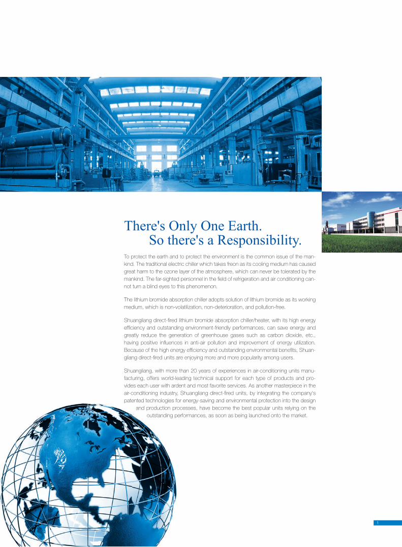
To protect the earth and to protect the environment is the common issue of the man-
kind. The traditional electric chiller which takes freon as its cooling medium has caused
great harm to the ozone layer of the atmosphere, which can never be tolerated by the
mankind. The far-sighted personnel in the fi eld of refrigeration and air conditioning can-
not turn a blind eyes to this phenomenon.
The lithium bromide absorption chiller adopts solution of lithium bromide as its working
medium, which is non-volatilization, non-deterioration, and pollution-free.
Shuangliang direct-fi red lithium bromide absorption chiller/heater, with its high en er gy
effi ciency and outstanding environment-friendly performances, can save en er gy and
greatly reduce the gen er a tion of greenhouse gases such as car bon dioxide, etc.,
having positive in fl u enc es in anti-air pollution and im prove ment of energy utilization.
Because of the high energy ef fi cien cy and out stand ing en vi ron men tal benefi ts, Shuan-
gliang direct-fi red units are en joy ing more and more pop u lar i ty among users.
Shuangliang, with more than 20 years of ex pe ri enc es in air-con di tion ing units manu-
facturing, offers world-lead ing tech ni cal sup port for each type of prod ucts and pro-
vides each user with ardent and most favorite services. As an oth er mas ter piece in the
air-con di tion ing industry, Shuangliang direct-fi red units, by in te grat ing the com pa ny's
pat ent ed tech nol o gies for en er gy-sav ing and en vi ron men tal pro tec tion into the design
and pro duc tion processes, have be come the best pop u lar units re ly ing on the
out stand ing performances, as soon as be ing launched onto the market.
There's Only One Earth. So there's a Responsibility.
2
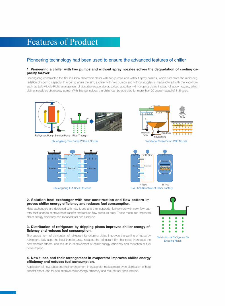
Pioneering technology had been used to ensure the advanced features of chiller
1. Pioneering a chiller with two pumps and without spray nozzles solves the degradation of cooling ca-pacity forever.Shuangliang constructed the fi rst in China absorption chiller with two pumps and without spray nozzles, which eliminates the rapid deg-
radation of cooling capacity. In order to attain the aim, a chiller with two pumps and without nozzles is manufactured with the knowhow,
such as Left-Middle-Right arrangement of absorber-evaporator-absorber, absorber with dripping plates instead of spray nozzles, which
did not needs solution spray pump. With this technology, the chiller can be operated for more than 20 years instead of 3~5 years.
Features of Product
2. Solution heat exchanger with new construction and flow pattern im-proves chiller energy efficiency and reduces fuel consumption.Heat exchangers are designed with new tubes and their supports, furthermore with new fl ow pat-
tern, that leads to improve heat transfer and reduce fl ow pressure drop. These measures improved
chiller energy effi ciency and reduced fuel consumption.
3. Distribution of refrigerant by dripping plates improves chiller energy ef-ficiency and reduces fuel consumption.The special form of distribution of refrigerant by dripping plates improves the wetting of tubes by
refrigerant, fully uses the heat transfer area, reduces the refrigerant fi lm thickness, increases the
heat transfer effects, and results in improvement of chiller energy effi ciency and reduction of fuel
consumption.
4. New tubes and their arrangement in evaporator improves chiller energy efficiency and reduces fuel consumption. Application of new tubes and their arrangement in evaporator makes more even distribution of heat
transfer effect, and thus to improve chiller energy effi ciency and reduce fuel consumption.
Distribution of Refrigerant By
Dripping Plates
Shuangliang E-A Shell Structure
Shuangliang Two Pump Without Nozzle Traditional Three Pump With Nozzle
E-A Shell Structure of Other Factory
A Type B Type
3
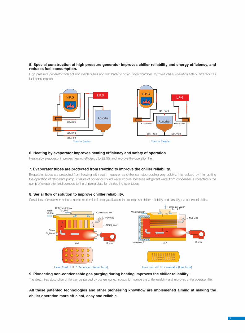
5. Special construction of high pressure generator improves chiller reliability and energy efficiency, and reduces fuel consumption. High pressure generator with solution inside tubes and wet back of combustion chamber improves chiller operation safety, and reduces
fuel consumption.
6. Heating by evaporator improves heating efficiency and safety of operationHeating by evaporator improves heating effi ciency to 92.5% and improve the operation life.
7. Evaporator tubes are protected from freezing to improve the chiller reliability.Evapotator tubes are protected from freezing with such measure, as chiller can stop cooling very quickly. It is realized by interruptting
the operation of refrigerant pump, if failure of power or chilled water occurs, because refrigerant water from condenser is collected in the
sump of evaporator, and pumped to the dripping plate for distributing over tubes.
8. Serial flow of solution to improve chilller reliability.Serial fl ow of solution in chiller makes solution fas fromcrystallization line to improve chilller reliability and simplify the control of chiller.
9. Pioneering non-condensable gas purging during heating improves the chiller reliability. The direct fi red absorption chiller can be purged by pioneering technology to improve the chiller reliability and improves chiller operation life.
All these patented technologies and other pioneering knowhow are implemened aiming at making the
chiller operation more efficient, easy and reliable.
Flow Chart of H.P. Generator (Water Tube) Flow Chart of H.P. Generator (Fire Tube)
Flow In Series Flow In Parallel
4
DFM technology
5
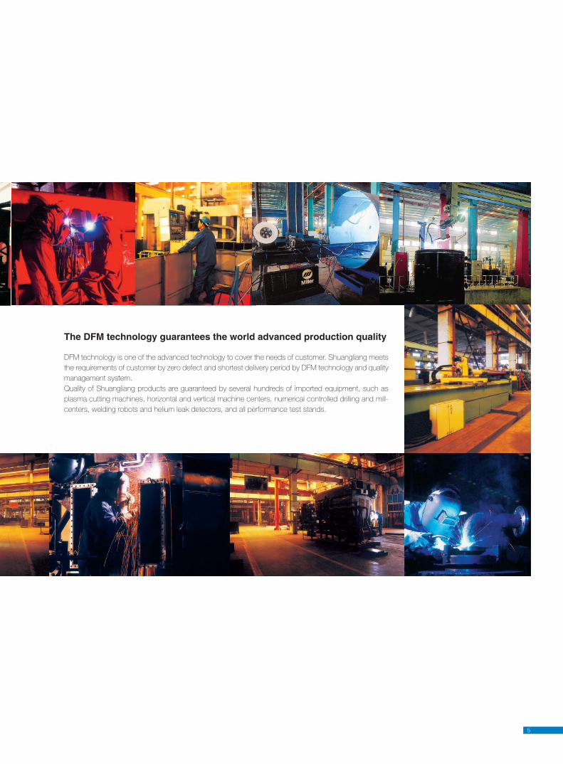
The DFM technology guarantees the world advanced production quality
DFM technology is one of the advanced technology to cover the needs of customer. Shuangliang meets
the requirements of customer by zero defect and shortest delivery period by DFM technology and quality
management system.
Quality of Shuangliang products are guaranteed by several hundreds of imported equipment, such as
plasma cutting machines, horizontal and vertical machine centers, numerical controlled drilling and mill-
centers, welding robots and helium leak detectors, and all performance test stands.
6
The Decisive Factor to Guarantee the Quality of Lithium Bromide Absorption ChillerLithium bromide absorption chiller is operating under high vacuum, which would be impaired by leaking of air into the chiller and non-
condensable gases produced in the chiller due to corrosion. Poor vacuum will reduce chiller cooling capacity and even increase the cor-
rosion of metal parts in a chiller. So high air-tightness is the decisive factor to guarantee the quality of lithium bromide absorption chiller,
and the key parameter for evaluation of chiller characteristics.
With High Air Tightness Will Bring High Pay BackH3 type DFAC is produced with high air-tightness, as several improving means had been adopted. The chiller is featured with leakage rate
of 1×10⁻¹⁰
Pa ·m3/s, which is 4 order lower than 2.03×10
-6Pa ·m
3/s specifi ed by Japanese Industrial Standard JISB8662-1994.
High air tightness will bring you pay backs in the following aspects:1 The degradaton of cooling capacity is solved in the possible way;
2 High reliable operation with less maintenance and repair cost is guaranteed;
3 Reliable operation of chiller more than 20 years is ensured.
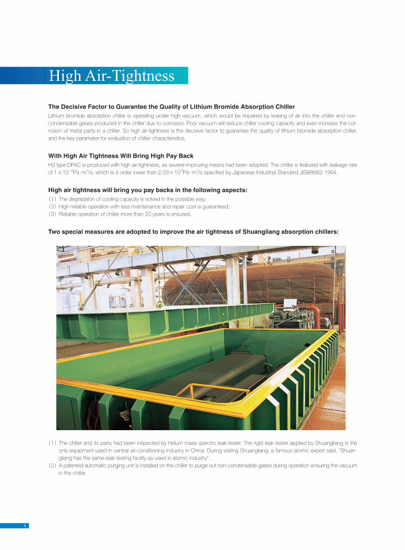
Two special measures are adopted to improve the air tightness of Shuangliang absorption chillers:
1 The chiller and its parts had been inspected by helium mass spectro leak tester. The rigid leak tester applied by Shuangliang is the
only equipment used in central air-conditioning industry in China. During visiting Shuangliang, a famous atomic expert said, "Shuan-
gliang has the same leak testing facility as used in atomic industry".
2 A patented automatic purging unit is installed on the chiller to purge out non-condensable gases during operation ensuring the vacuum
in the chiller.
High Air-Tightness
7
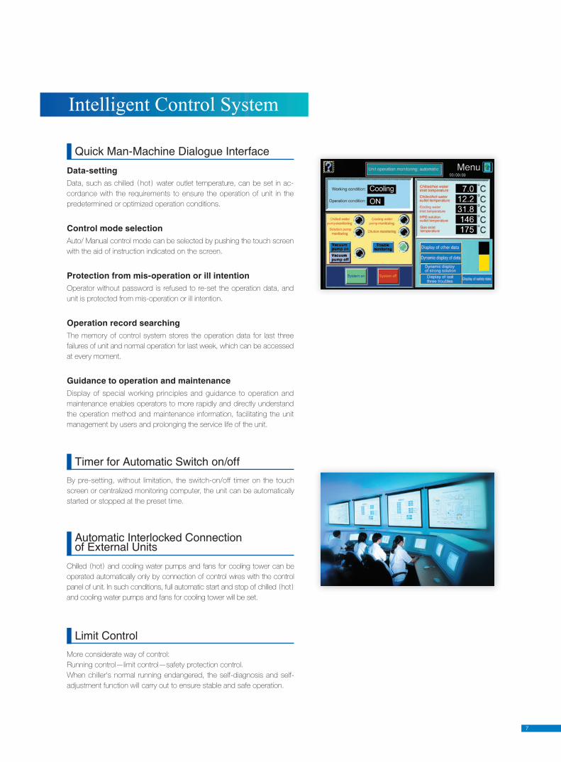
Data-settingData, such as chilled hot water out let temperature, can be set in ac-
cordance with the re quire ments to ensure the op er a tion of unit in the
predetermined or optimized operation conditions.
Control mode selectionAuto/ Manual control mode can be se lect ed by pushing the touch screen
with the aid of instruction indicated on the screen.
Protection from mis-operation or ill intentionOperator with out pass word is refused to re-set the op er a tion data, and
unit is protected from mis-op er a tion or ill intention.
Operation record searchingThe memory of control sys tem stores the op er a tion data for last three
failures of unit and normal op er a tion for last week, which can be ac cess ed
at every moment.
Guidance to operation and maintenanceDisplay of spe cial working prin ci ples and guidance to op er a tion and
main te nance enables op er a tors to more rapidly and di rect ly understand
the operation method and main te nance information, facilitating the unit
man age ment by us ers and pro long ing the service life of the unit.
Quick Man-Machine Dialogue Interface
Limit Control
More considerate way of control:
Running control—limit control—safety protection control.
When chiller's normal running endangered, the self-diagnosis and self-
adjustment function will carry out to ensure stable and safe operation.
Chilled hot and cooling water pumps and fans for cool ing tow er can be
operated automatically only by con nec tion of control wires with the con trol
panel of unit. In such conditions, full automatic start and stop of chilled hot
and cooling water pumps and fans for cooling tower will be set.
Automatic Interlocked Connectionof Ex ter nal Units
By pre-setting, without limitation, the switch-on/off timer on the touch
screen or centralized monitoring computer, the unit can be au to mat i cal ly
started or stopped at the preset time.
Timer for Automatic Switch on/off
Intelligent Control System
8
The cooling water fl ow can be adjusted in accordance with the opera-
tion mode of unit by means of the Inverter, which control the operation of
water pump. In such a way the consumption of en er gy by the pump can
be saved, and unit can be operated under lower temperature of cooling
water. Then the unit can be operated under full load even at lower tem-
perature of cooling water. The control func tions are optional for order.
Inverter Control of Cool ing Water Pump for Stable Operation and Saving of Energy
The start and shutdown of unit can be realized by press ing the Start/
Stop buttons in the control room remotely and the op er a tion status can
be displayed through indicator lights to operate and know the unit data
with out the need to be on the site. Under special requirement, the touch
screen can be installed in the control room to know the op er a tion status
of the unit and op er a tion data and in for ma tion of each part of the unit
anytime, thus to monitor the unit on a real time basis as well as to store
and print the operation data.
The company's monitoring and control center is able to carry out patrol
inspection on the units located in the us ers' machine room to know and
analyze the operation sta tus of the units anytime. Should there be any ab-
normity during the operation, the control system will au to mat i cal ly dial and
connect to the com pa ny's monitoring and control center and the ser vice
en gi neer responsible for this unit by sending out fail ure information.
The control functions are optional for order.
Remote Monitoring System for Real Time Su per vi sion of the Op er a tion System
The central control of a building is supported by the con trol system. The
unit control panel is provided with in ter fac es RS232, RS422 or RS485
and data communication protocol for ac qui si tion and displaying of the
operation data and con trol of the unit realized by the control system of a
building. The control func tions are optional for order.
Flexible Connection with Centralized Control of Buildings
Central control of units, such as automatic change-over, central control,
storage and print-out of operation data of parallel op er at ed units, and
etc. can be realized by means of a computer with the software MMI2 for
cen tral ized control developed by the company. In such a way, the com-
put er automatically displays the operation data and conditions, troubles
and alarm signal and starts or stops the units, when the load increases
or decreases, and the energy consumption can be saved. The control
func tions are optional for order.
Reliable and Easy Centralized Control System
9
Intelligent Control System
The solution con cen tra tion control, specifi c to the company, al-
lows the unit to operate under high con cen tra tion safely and
sta bly by mon i tor ing the spray concentration of the con cen trat ed
so lu tion and controlling the heating capacity, thus not only to pre-
vent crys tal li za tion but also to im prove the operation ef fi cien cy of
the unit.
Concentration Lim it ControlShuangliang Company uses the most advanced in the world color touch screen as the man-machine interface. The op-erator can start or stop the unit or learn the basic operation, maintenance and acquisition of op er a tion mode and data merely by touching the screen in accordance with the instruc-tion displayed. Man-ma chine dialogue by touch screen will make the operation of Shuangliang made units easier and more accessible.
When failure of the unit occurs, the location, reason and rem e dy of fail ure shall be displayed by means of interface, thus makes the opera-
tor to treat the failure conditions easier and quicker, and improve the op er a tion effi ciency of the unit. The control system also automatically
keeps in the memory op er a tion al data in a week and contents of last 5 failures and of last 3 failures as well as various parameters for check
at anytime.
Failure Management System
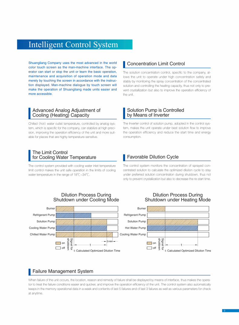
The control system monitors the con cen tra tion of sprayed con-
cen trat ed solution to cal cu late the optimized dilution cycle to stay
un der preferred solution concentration during shutdown, thus not
only to prevent crys tal li za tion but also to decrease the re-start time.
Favorable Dilution Cycle
The control system provided with cooling water inlet tem per a ture
limit control makes the unit safe operation in the limits of cooling
water tem per a ture in the range of 18℃~34℃.
The Limit Controlfor Cooling Water Tem per a ture
The Inverter control of solution pump, adopted in the con trol sys-
tem, makes the unit op er ate under best solution fl ow to improve
the operation efficiency and reduce the start time and energy
consumption.
Solution Pump is Controlledby Means of Inverter
Chilled hot wa ter out let temperature, con trolled by an a log sys-
tem, which is spe cifi c for the company, can sta bi lize at high preci-
sion, improving the operation ef fi cien cy of the unit and more suit-
able for plac es that are high ly tem per a ture-sensitive.
Advanced Analog Adjustment of Cool ing (Heating) Ca pac i ty
Dilution Process During Shutdown under Cooling Mode
Dilution Process During Shutdown under Heating Mode
10
The control system adopts the advanced PID con trol tech-
nol o gy and touch screen LCD to display the operation con-
ditions and data of the unit in a real-time manner with both
texts and pictures, fea tur ing direct ex pres sion of contents and
easiness for understanding, enabling the operator to know the
operation conditions anytime and to take time ly measures in
emergency.
Real-Time Display of Operation Direct and Easy to Understand
This function ensures that the operator can un der stand the unit easily
and rapidly thus to well manage the unit and greatly im prove the life of
the unit and guarantee the increase of ef fi cien cy for users as well.
Specifi c Working Principle and Operation and Main te nance In struc tions Displaying
Display of Parameters
Data
Dis
pla
y
Chilled (hot) water inlet temperature Evaporating temperature
Chilled (hot) water outlet temperature Flue gas temperature
Cooling water inlet temperature HPG pressure
Intermediate concentratedsolution temperature from HPG
Pressure of auto purging unit
Concentrated solution temperature from LPG
Chiller operation time
Concentrated solution spray temperature
Vacuum pump start/stop number
Condensation temperature Concentrated solution dynamic
De-crystallizing pipe temperature
Workingprinciple
Cooling flow chart Heating flow chart
Working principle of chiller Working principle of heater
Op
era
tion in
stru
ctio
ns
Operation of chiller Refrigerant by-pass
Operation of heater Leak test of unit
Operation of chilled (hot)and cooling water pumps
Solution charge
Burner operation Removal of solution from unit
Operation of vacuum pump Rotation direction test
for canned motor-pumps
Sampling of refrigerant Change of valve sealing rings
Main
tenance
instru
ctio
ns
Routing maintenance
CoolingUnit
System
HeatingUnit
System
Long term shutdown
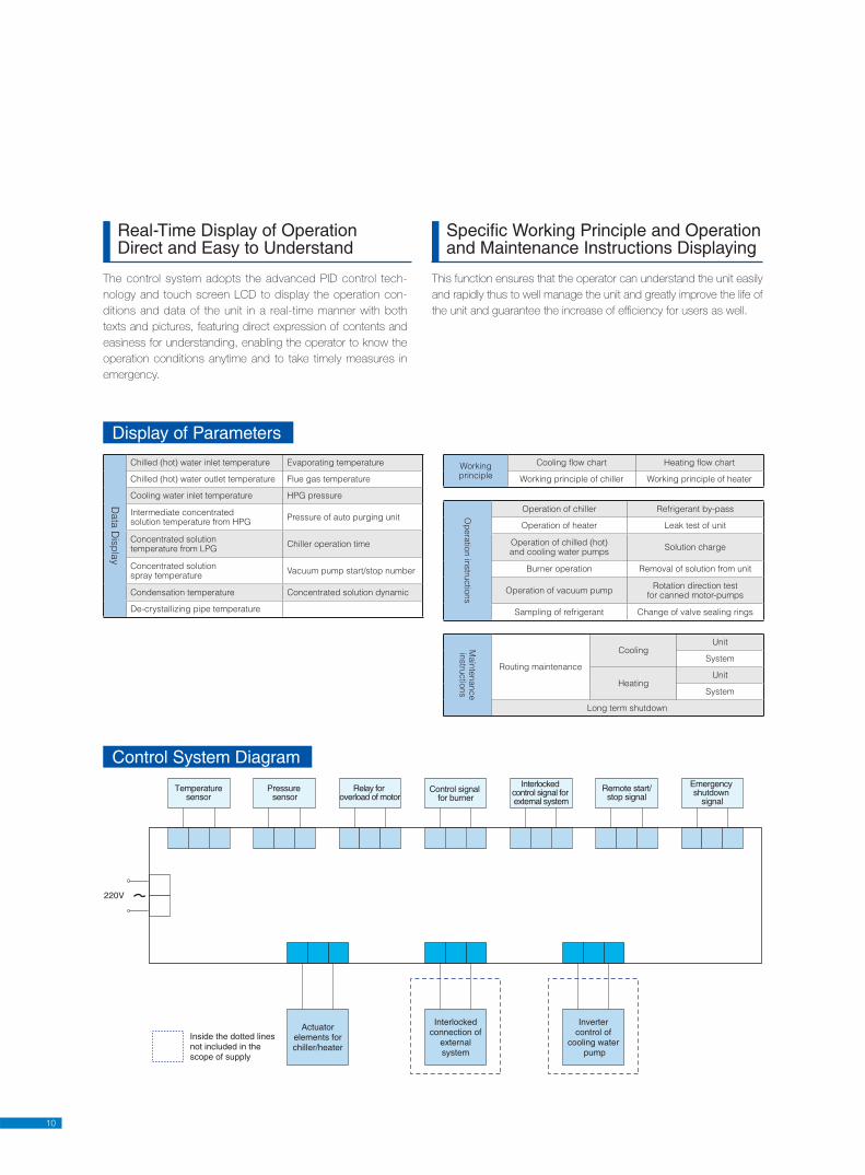
Control System Diagram
11
Certificates
12
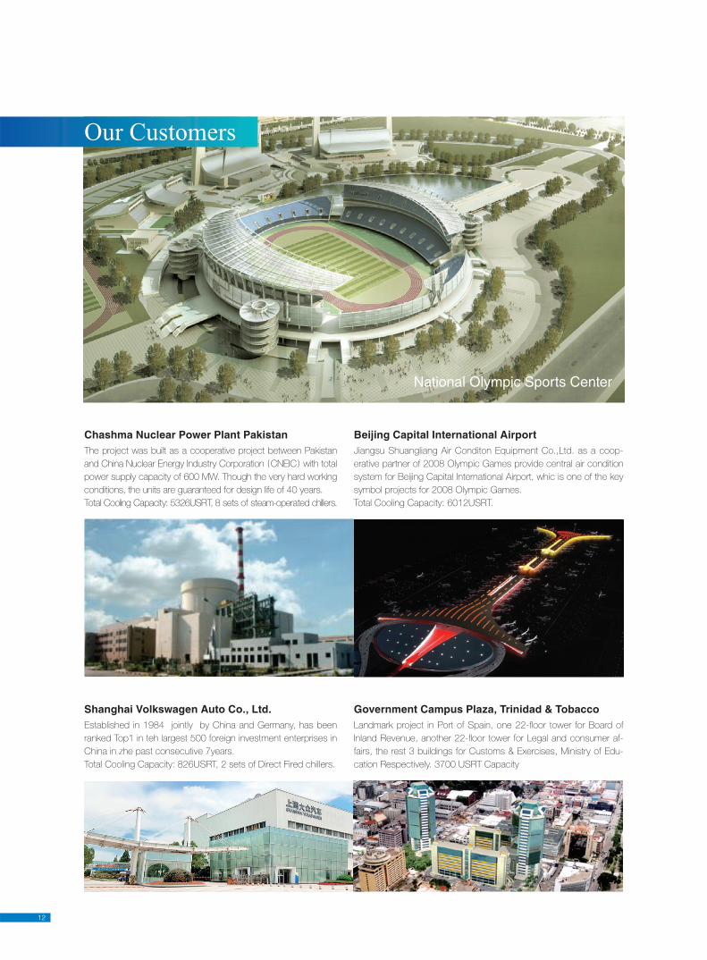
National Olympic Sports Center
Shanghai Volkswagen Auto Co., Ltd.Established in 1984 jointly by China and Germany, has been
ranked Top1 in teh largest 500 foreign investment enterprises in
China in zhe past consecutive 7years.
Total Cooling Capacity: 826USRT, 2 sets of Direct Fired chillers.
Government Campus Plaza, Trinidad & TobaccoLandmark project in Port of Spain, one 22-fl oor tower for Board of
Inland Revenue, another 22-fl oor tower for Legal and consumer af-
fairs, the rest 3 buildings for Customs & Exercises, Ministry of Edu-
cation Respectively. 3700 USRT Capacity
Chashma Nuclear Power Plant PakistanThe project was built as a cooperative project between Pakistan
and China Nuclear Energy Industry Corporation CNEIC with total
power supply capacity of 600 MW. Though the very hard working
conditions, the units are guaranteed for design life of 40 years.
Total Cooling Capacity: 5326USRT, 8 sets of steam-operated chillers.
Beijing Capital International AirportJiangsu Shuangliang Air Conditon Equipment Co.,Ltd. as a coop-
erative partner of 2008 Olympic Games provide central air condition
system for Beijing Capital International Airport, whic is one of the key
symbol projects for 2008 Olympic Games.
Total Cooling Capacity: 6012USRT.
Our Customers
13
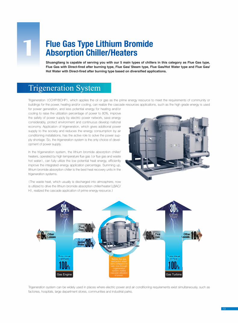
Trigeneration CCHP/BCHP , which applies the oil or gas as the prime energy resource to meet the requirements of community or
buildings for the power, heating and/or cooling, can realize the cascade resources applications, such as the high grade energy is used
for power generation, and less potential energy for heating and/or
cooling to raise the utilization percentage of power to 80%, improve
the safety of power supply by electric power network, save energy
considerably, protect environment and continuous develop national
economy. Application of trigeneration, which gives additional power
supply to the society and reduces the energy consumption by air
conditioning installations, has the active role to solve the power sup-
ply shortage. So, the trigeneration system is the only choice of devel-
opment of power supply.
In the trigeneration system, the lithium bromide absorption chiller/
heaters, operated by high temperature fl ue gas or fl ue gas and waste
hot water , can fully utilize the low potential heat energy, efficiently
improve the integrated energy application percentage. Summing up,
lithium bromide absorption chiller is the best heat recovery units in the
trigeneration systems.
The waste heat, which usually is discharged into atmosphere, now
is utilized to drive the lithium bromide absorption chiller/heater LBAC/
H , realized the cascade application of prime energy resource.
Trigeneration System
Trigeneration system can be widely used in places where electric power and air conditioning requirements exist simultaneously, such as
factories, hospitals, large department stores, communities and industrial parks.
Flue Gas Type Lithium Bromide Absorption Chiller/Heaters1Shuangliang is capable of serving you with our 5 main types of chillers in this category as Flue Gas type, Flue Gas with Direct-fired after burning type, Flue Gas/ Steam type, Flue Gas/Hot Water type and Flue Gas/Hot Water with Direct-fired after burning type based on diversified applications.
Gas Engine Gas Turbine
ElectricPowerElectricPower
ElectricPowerElectricPower
14
Flue gas type lithium bromide absorption chiller/heaters are oper-
ated by the fl ue gas from generators and other heat sources, fall
into two categories: flue gas type and flue gas/hot water type.
High temperature flue gas type absorption chiller/heaters are
mainly applicable to the trigeneration installations with turbo gen-
erators including micro turbine and other places where high
temperature fl ue gas is available and air conditioning is necessary
such as industrial kilns . For fl ue gas-hot water fi red types, main
heat sources can fi nd the fl ue gas and jacket water from internal
combustion engine. These types can also be used in other places
where high temperature fl ue gas is available and air conditioning is
necessary.
In order to meet the requirements to comfort and technological
needs of air conditioning system, lithium bromide absorption chill-
er/heaters with after-burning means can be installed, where heat
from generator fl ue gas or fl ue gas and hot water is not enough
to drive them.
For trigenerator installation with internal combustion engine as
drive, if fl ue gas is enough to meet the requirements of air condi-
tioning, and hot water will be used for other applications, then fl ue
gas type or such type with after-burning will be available.
Flue Gas Type Lithium Bromide Absorption Chiller/heaters
Typical Modes for Application of Trigeneration Systemwith Flue Gas type Lithium Bromide Absorotion Chiller/Heaters
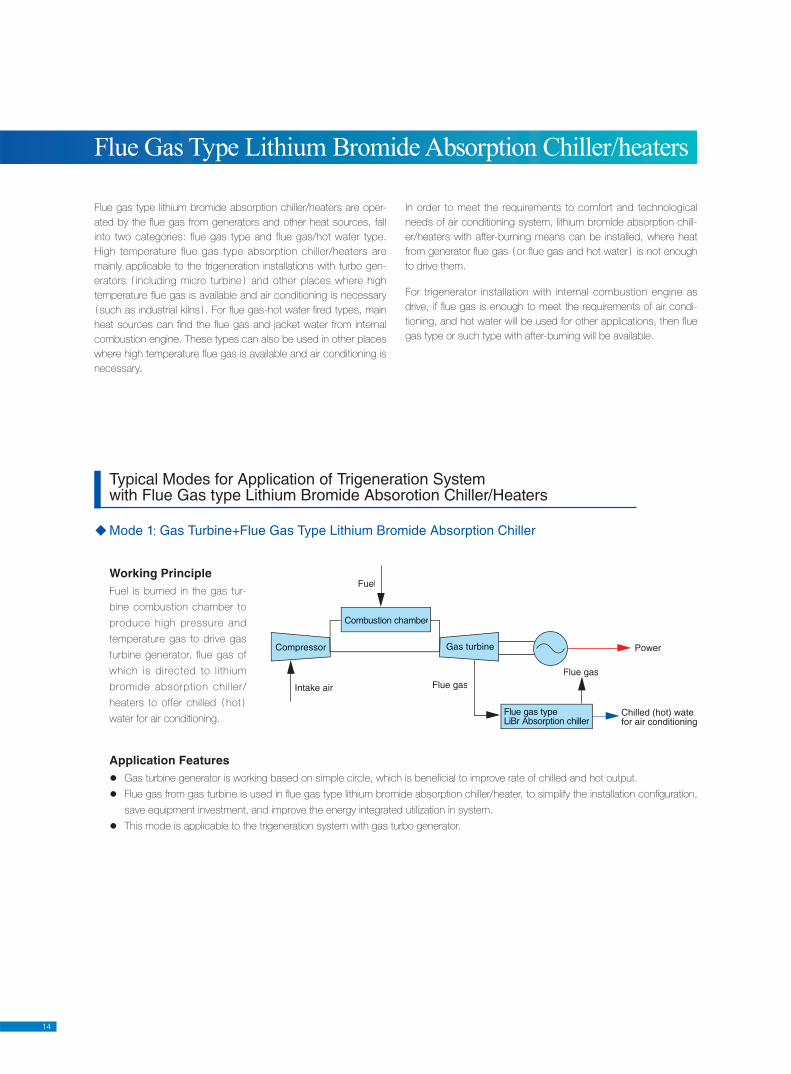
Mode 1: Gas Turbine+Flue Gas Type Lithium Bromide Absorption Chiller
Compressor
Intake air
Fuel
Combustion chamber
Gas turbine
Flue gasFlue gas
Flue gas typeLiBr Absorption chiller
Power
Chilled (hot) watefor air conditioning
Application FeaturesGas turbine generator is working based on simple circle, which is benefi cial to improve rate of chilled and hot output.
Flue gas from gas turbine is used in fl ue gas type lithium bromide absorption chiller/heater, to simplify the installation confi guration,
save equipment investment, and improve the energy integrated utilization in system.
This mode is applicable to the trigeneration system with gas turbo generator.
Working PrincipleFuel is burned in the gas tur-
bine combustion chamber to
produce high pressure and
temperature gas to drive gas
turbine generator, flue gas of
which is directed to lithium
bromide absorption chil ler/
heaters to offer chilled hot
water for air conditioning.
15
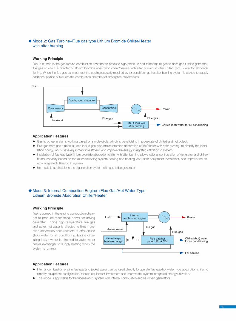
Mode 2: Gas Turbine+Flue gas type Lithium Bromide Chiller/Heater with after burning
Working PrincipleFuel is burned in the gas turbine combustion chamber to produce high pressure and temperature gas to drive gas turbine generator,
fl ue gas of which is directed to lithium bromide absorption chiller/heaters with after burning to offer chilled hot water for air condi-
tioning. When the fl ue gas can not meet the cooling capacity required by air-conditioning, the after burning system is started to supply
additional portion of fuel into the combustion chamber of absorption chiller/heater.
Application FeaturesGas turbo generator is working based on simple circle, which is benefi cial to improve rate of chilled and hot output.
Flue gas from gas turbine is used in fl ue gas type lithium bromide absorption chiller/heater with after burning, to simplify the instal-
lation confi guration, save equipment investment, and improve the energy integrated utilization in system.
Installation of fl ue gas type lithium bromide absorption chiller with after burning allows rational confi guration of generator and chiller/
heater capacity based on the air conditioning system cooling and heating load, safe equipment investment, and improve the en-
ergy integrated utilization in system.
his mode is applicable to the trigeneration system with gas turbo generator
Mode 3: Internal Combustion Engine +Flue Gas/Hot Water Type Lithium Bromide Absorption Chiller/Heater
Application FeaturesInternal combustion engine fl ue gas and jacket water can be used directly to operate fl ue gas/hot water type absorption chiller to
simplify equipment confi guration, reduce equipment investment and improve the system integrated energy utilization.
This mode is applicable to the trigeneration system with internal combustion engine driven generators
Flue
Combustion chamber
Compressor
Intake air
Gas turbine
Flue gas
LiBr A C/H withafter burning
Flue gas
Power
Chilled (hot) water for air conditioning
Fuel
Jacket water
Internalcombustion engine
Flue gas
Flue gas
Water-waterheat exchanger
Flue gas/hotwater LiBr A C/H
Power
Chilled (hot) waterfor air conditioning
For heating
Working PrincipleFuel is burned in the engine combustion cham-
ber to produce mechanical power for driving
generator. Engine high temperature flue gas
and jacket hot water is directed to lithium bro-
mide absorption chiller/heaters to offer chilled
hot water for air conditioning. Engine circu-
lating jacket water is directed to water-water
heater exchanger to supply heating when the
system is running.
16
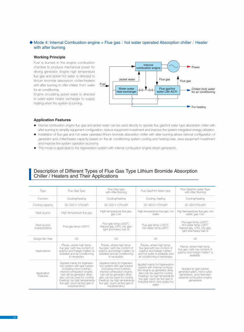
Mode 4: Internal Combustion engine + Flue gas/hot water operated Absorption chiller/Heater with after burning
Working PrincipleFuel is burned in the engine combustion
chamber to produce mechanical power for
driving generator. Engine high temperature
fl ue gas and jacket hot water is directed to
lithium bromide absorption chiller/heaters
with after burning to offer chilled hot water
for air conditioning.
Engine circulating jacket water is directed
to water-water heater exchanger to supply
heating when the system is running.
Application FeaturesInternal combustion engine fl ue gas and jacket water can be used directly to operate fl ue gas/hot water type absorption chiller with
after burning to simplify equipment confi guration, reduce equipment investment and improve the system integrated energy utilization.
Installation of fl ue gas and hot water operated lithium bromide absorption chiller with after burning allows rational confi guration of
generator and chiller/heater capacity based on the air conditioning system cooling and heating load, save equipment investment
and improve the system operation economy.
This mode is applicable to the trigeneration system with internal combustion engine driven generators.
Description of Different Types of Flue Gas Type Lithium Bromide Absorption Chiller / Heaters and Their Applications
Type Flue Gas TypeFlue Gas type
with After BurningFlue Gas/Hot Water type
Flue Gas/Hot water Typewith After Burning
Function Cooling/heating Cooling/heating Cooling, healing Cooling/heating
Cooling capacity 30~300×104kcal/h 30~300×10
4kcal/h 30~800×10
4kcal/h 30~80010
4kcal/h
Heat source High temperature fl ue gasHigh temperature fl ue gas,
gas oilHigh temperature fl ue gas, hot
waterHig htemperature fl ue gas, hot
water, gas oil
Heat sourcecharacteristics
Flue gas temp.≥250℃Flue gas temp.≥250℃
Natural gas, LPG, city gas, light and heavy fuel oil
Flue gas temp.≥250℃Hot water temp.≥90℃
Flue gas temp.≥250℃Hot water temp.≥90℃
Natural gas, LPG, city gas, light and heavy fuel oil
Design life, Year 20 20 20 20
Applications
Places, where high temp. fl ue gas with low content of sulphur and foreign matter is available and air conditioning
is necessary.
Places, where high temp. fl ue gas with low content of sulphur and foreign matter is available and air conditioning
is necessary.
Places, where high temp. fl ue gas with low content of sulphur and foreign matter
and hot water is available and air conditioning is necessary.
Places, where high temp. fl ue gas with low content of sulphur and foreign matter is
available.
ApplicationFeatures
Applied mainly for trigenera-tion system with gas turbine
including micro turbine , internaI combustion engine, fuel cell as generator drive,
also can be used for cooling heating by high temperature fl ue gas such as fl ue gas of
industrial kilns
Applied mainly for trigenera-tion system with gas turbine
including micro turbine , internal combustion engine, fuel cell as generator drive,
also can be used for cooling heating by high temperature fl ue gas such as fl ue gas of
industrial kilns
Applied mainly for trigeneration system with internal combus-tion engine as generator drive, also can be used for cooling heating by high temperature fl ue gas such as fl ue gas of industrial kilns and waste hot
water
Applied for gas turbine generator plant, micro-turbo generators, and internalan
external combustion engine generators
Fuel
Internalcombustion engine
Jacket water Flue gasFlue gas
Power
Water-waterheat exchanger
Flue gas/hotwater LiBr AC/H
Chilled (hot) waterfor air conditioning
For heating

17
Flue gas type lithium bromide absorption chiller/heater is a equipment, which uses high temperature fl ue gas discharged by gas turbine
installation, as fuel, water as refrigerant, lithium bromide as absorbent solution, produces chilled and/or hot water for the purpose of air-
conditioning and technology process. It consists of fl ue gas high pressure generator HP generator , low pressure generator LP gen-
erator , condenser, evaporator, absorber, high temperature heat exchanger HT heat exchanger , low temperature heat exchanger LT
heat exchanger ; and such auxiliary parts, as hermetically-sealed pumps and vacuum pump, and keeps itself under vacuum conditions
by vacuum pump and automatic purge unit
Working Principle
Refrigerating cycle and its Features
Flue gas type absorption chiller/heaters
Cooling waterinlet
Chilled waterinlet
Chilled wateroutlet
Cooling wateroutlet
Refrigerant pump
HT heatexchanger
Condenser
AbsorberEvaporator
Flu
e g
as e
xhaust
HP Generator
3Check valve
Samplingvalve
ExhaustVacuum pump
Oil tra
p
Auto
purg
ing
unit
Auto
de-c
rysta
-lliz
atio
n p
ipe
LP Generator
Flue gas inlet
Cooler
Cooler inlet valve
Bypassvalve
Absorber
Solution pump
LT heatexchanger
① Chilled water inlet temp. (I)
② Chilled water outlet temp. (C,I,A)
③ Cooling water inlet temp. (C,I,A)
④ Auto purging unit pressure (I)
⑤ LP generator Concentrated solution temp. (C,I)
⑥ Condensation temp. (C,I,A)
⑦ HP generator intermediate concentrated
solution temp. (I,A)
⑧ Evaporation temp. (I,A)
⑨ Chilled water flow (A)
⑩ De-crystallization pipe temp. (I,A)
⑪ HP generator pressure (C,I,A)
⑫ Concentrated solution spraying temp. (C,I)
⑬ HP solution level(C,I))
⑭ Flue gas inlet temp. (I)
⑮ Flue gas exhausted temp. (I)
Chilled water
Cooling water
Refrigerant water
HP refrigerant vapor
Diluted solution
Intermediate solution
Concentrated solution
Refrigerant vapor
(A)-Alarm
(I)-Indication
(C)-Control
Max. design capacity: 3300USRt. Inlet temp. of flue gas ≥250℃, flue gas is required to be clean and corrosion-free while having qualified back pressure for it’s clearance induct fan shall be introduced into the system if such back pressure is not sufficient . Our standardized series of chillers have 430~520℃ and 170℃ for flue gas inlet/outlet temp. respectively, chilled water inlet/outlet temp. 12/7℃, hot water inlet/outlet temp. 56/60℃, cooling water inlet/outlet temp. 32/38℃.Please consult with our technical dept. for details and other applications.
18
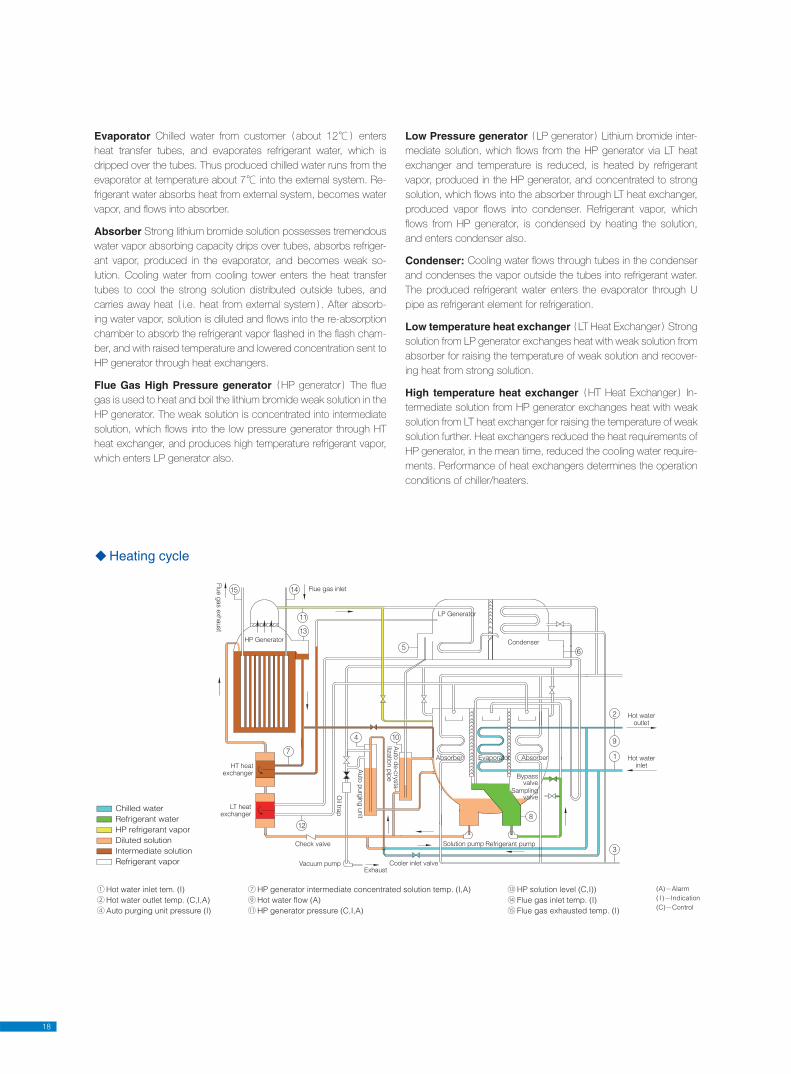
Evaporator Chilled water from customer about 12℃ enters
heat transfer tubes, and evaporates refrigerant water, which is
dripped over the tubes. Thus produced chilled water runs from the
evaporator at temperature about 7℃ into the external system. Re-
frigerant water absorbs heat from external system, becomes water
vapor, and fl ows into absorber.
Absorber Strong lithium bromide solution possesses tremendous
water vapor absorbing capacity drips over tubes, absorbs refriger-
ant vapor, produced in the evaporator, and becomes weak so-
lution. Cooling water from cooling tower enters the heat transfer
tubes to cool the strong solution distributed outside tubes, and
carries away heat i.e. heat from external system . After absorb-
ing water vapor, solution is diluted and fl ows into the re-absorption
chamber to absorb the refrigerant vapor fl ashed in the fl ash cham-
ber, and with raised temperature and lowered concentration sent to
HP generator through heat exchangers.
Flue Gas High Pressure generator HP generator The fl ue
gas is used to heat and boil the lithium bromide weak solution in the
HP generator. The weak solution is concentrated into intermediate
solution, which fl ows into the low pressure generator through HT
heat exchanger, and produces high temperature refrigerant vapor,
which enters LP generator also.
Low Pressure generator LP generator Lithium bromide inter-
mediate solution, which fl ows from the HP generator via LT heat
exchanger and temperature is reduced, is heated by refrigerant
vapor, produced in the HP generator, and concentrated to strong
solution, which fl ows into the absorber through LT heat exchanger,
produced vapor fl ows into condenser. Refrigerant vapor, which
fl ows from HP generator, is condensed by heating the solution,
and enters condenser also.
Condenser: Cooling water fl ows through tubes in the condenser
and condenses the vapor outside the tubes into refrigerant water.
The produced refrigerant water enters the evaporator through U
pipe as refrigerant element for refrigeration.
Low temperature heat exchanger LT Heat Exchanger Strong
solution from LP generator exchanges heat with weak solution from
absorber for raising the temperature of weak solution and recover-
ing heat from strong solution.
High temperature heat exchanger HT Heat Exchanger In-
termediate solution from HP generator exchanges heat with weak
solution from LT heat exchanger for raising the temperature of weak
solution further. Heat exchangers reduced the heat requirements of
HP generator, in the mean time, reduced the cooling water require-
ments. Performance of heat exchangers determines the operation
conditions of chiller/heaters.
Hot waterinlet
Hot wateroutlet
HP Generator Condenser
LP Generator
Flu
e g
as e
xhaust
Flue gas inlet
Check valve
ExhaustVacuum pump Cooler inlet valve
AbsorberEvaporator
Samplingvalve
Bypassvalve
Absorber
Refrigerant pumpSolution pump
HT heatexchanger
Oil tra
p
Auto
purg
ing
unit
Auto
de-c
rysta
-lliz
atio
n p
ipe
LT heatexchanger
Chilled water
Refrigerant water
HP refrigerant vapor
Diluted solution
Intermediate solution
Refrigerant vapor
(A)-Alarm
( I )-Indication
(C)-Control
① Hot water inlet tem. (I)
② Hot water outlet temp. (C,I,A)
④ Auto purging unit pressure (I)
⑦ HP generator intermediate concentrated solution temp. (I,A)
⑨ Hot water flow (A)
⑪ HP generator pressure (C,I,A)
⑬ HP solution level (C,I))
⑭ Flue gas inlet temp. (I)
⑮ Flue gas exhausted temp. (I)
Heating cycle
19
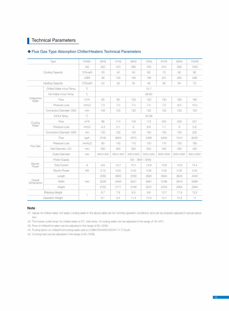
Technical Parameters
Flue Gas Type Absorption Chiller/Heaters Technical Parameters
Note1 Values for chilled water, hot water, cooling water in the above table are for nominal operation conditions, and can be properly adjusted in actual opera-
tion.
2 The lowest outlet temp. for chilled water is 5℃. Inlet temp. of cooling water can be adjusted in the range of 18~34℃.
3 Flow of chilled/hot water can be adjusted in the range of 60~120%.
4 Fouling factor on chilled/hot/cooling water side is 0.086m2K/kW 0.0001m
2·h ·℃/kcal .
5 Cooling load can be adjusted in the range of 20~100%.
Type YX480- 35H2 47H2 58H2 70H2 81H2 93H2 105H2
Cooling Capacity
kW 350 470 580 700 810 930 1050
104kcal/h 30 40 50 60 70 80 90
USRt 99 132 165 198 231 265 298
Heating Capacity 104kcal/h 24 32 40 48 56 64 72
Chilled/Hot Water
Chilled Water in/out Temp. ℃ 12-7
Hot Water in/out Temp. ℃ 56-60
Flow m3/h 60 80 100 120 140 160 180
Pressure Loss mH2O 7.0 7.0 7.0 7.5 7.5 8.0 10.0
Connection Diameter DN mm 100 100 125 125 150 150 150
Cooling Water
In/Out Temp. ℃ 32-38
Flow m3/h 86 114 143 172 200 229 257
Pressure Loss mH2O 4.3 5.1 6 6.8 7.1 9 5.6
Connection Diameter DN mm 100 125 150 150 150 150 200
Flue Gas
Flow kg/h 2745 3655 4570 5485 6400 7310 8225
Pressure Loss mmH2O 80 140 115 120 170 130 165
Inlet Diameter Φ mm 300 300 350 350 400 400 450
Outlet Diameter mm 400×400 450×450 500×500 550×550 600×600 600×600 650×650
Electric Power
Power Supply 3Φ - 380V - 50Hz
Total Current A 9.6 10.7 10.7 13.8 13.8 13.8 14.4
Electric Power kW 3.15 3.55 3.55 4.35 4.35 4.35 4.55
Overall Dimensions
Length
mm
3780 3800 3783 3820 3840 3840 4340
Width 2239 2349 2551 2661 2786 2816 2836
Height 2152 2171 2169 2231 2316 2364 2384
Shipping Weightt
6.7 7.8 9.3 9.8 10.7 11.9 13.2
Operation Weight 8.1 9.4 11.4 12.3 13.7 15.3 17
20
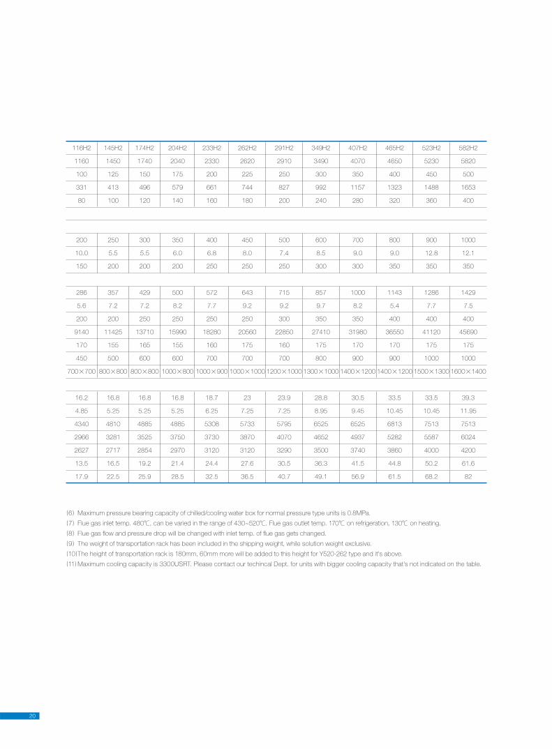
116H2 145H2 174H2 204H2 233H2 262H2 291H2 349H2 407H2 465H2 523H2 582H2
1160 1450 1740 2040 2330 2620 2910 3490 4070 4650 5230 5820
100 125 150 175 200 225 250 300 350 400 450 500
331 413 496 579 661 744 827 992 1157 1323 1488 1653
80 100 120 140 160 180 200 240 280 320 360 400
200 250 300 350 400 450 500 600 700 800 900 1000
10.0 5.5 5.5 6.0 6.8 8.0 7.4 8.5 9.0 9.0 12.8 12.1
150 200 200 200 250 250 250 300 300 350 350 350
286 357 429 500 572 643 715 857 1000 1143 1286 1429
5.6 7.2 7.2 8.2 7.7 9.2 9.2 9.7 8.2 5.4 7.7 7.5
200 200 250 250 250 250 300 350 350 400 400 400
9140 11425 13710 15990 18280 20560 22850 27410 31980 36550 41120 45690
170 155 165 155 160 175 160 175 170 170 175 175
450 500 600 600 700 700 700 800 900 900 1000 1000
700×700 800×800 800×800 1000×800 1000×900 1000×1000 1200×1000 1300×1000 1400×1200 1400×1200 1500×1300 1600×1400
16.2 16.8 16.8 16.8 18.7 23 23.9 28.8 30.5 33.5 33.5 39.3
4.85 5.25 5.25 5.25 6.25 7.25 7.25 8.95 9.45 10.45 10.45 11.95
4340 4810 4885 4885 5308 5733 5795 6525 6525 6813 7513 7513
2966 3281 3525 3750 3730 3870 4070 4652 4937 5282 5587 6024
2627 2717 2854 2970 3120 3120 3290 3500 3740 3860 4000 4200
13.5 16.5 19.2 21.4 24.4 27.6 30.5 36.3 41.5 44.8 50.2 61.6
17.9 22.5 25.9 28.5 32.5 36.5 40.7 49.1 56.9 61.5 68.2 82
6 Maximum pressure bearing capacity of chilled/cooling water box for normal pressure type units is 0.8MPa.
7 Flue gas inlet temp. 480℃, can be varied in the range of 430~520℃. Flue gas outlet temp. 170℃ on refrigeration, 130℃ on heating.
8 Flue gas fl ow and pressure drop will be changed with inlet temp. of fl ue gas gets changed.
9 The weight of transportation rack has been included in the shipping weight, while solution weight exclusive.
10 The height of transportation rack is 180mm, 60mm more will be added to this height for Y520-262 type and it's above.
11 Maximum cooling capacity is 3300USRT. Please contact our techincal Dept. for units with bigger cooling capacity that's not indicated on the table.
21
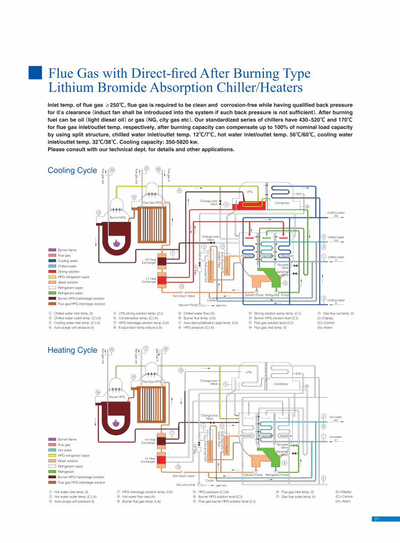
Inlet temp. of flue gas ≥250℃, flue gas is required to be clean and corrosion-free while having qualified back pressure for it’s clearance induct fan shall be introduced into the system if such back pressure is not sufficient . After burning fuel can be oil light diesel oil or gas NG, city gas etc . Our standardized series of chillers have 430~520℃ and 170℃ for flue gas inlet/outlet temp. respectively, after burning capacity can compensate up to 100% of nominal load capacity by using split structure, chilled water inlet/outlet temp. 12℃/7℃, hot water inlet/outlet temp. 56℃/60℃, cooling water inlet/outlet temp. 32℃/38℃. Cooling capacity: 350-5820 kw.Please consult with our technical dept. for details and other applications.
Flue Gas with Direct-fi red After Burning Type Lithium Bromide Absorption Chiller/Heaters
By-passValve
SamplingValve
Cooler
gas out
Non-return valve
Vacuum pump
Solution Pump Refrigerant Pump
LPG
Absorber
LT HeatExchanger
HT HeatExchanger
Auto
-purg
e U
nit
Oil Tra
p
Auto
-decry
sta
-lliz
atio
n P
ipe
Change-overValve
Change-overValve
flue g
as o
ut
gas flu
e in
flue g
as o
ut
AbsorberEvaporator
Condensor
hot waterin
hot waterout
Burner HPG
Flue Gas HPG
Burner flame
Flue gas
Hot water
HPG refrigerant vapor
Weak solution
Refrigerant vapor
Refrigerant
Burner HPG ineterstage solution
Flue gas HPG interstage solution
① Hot water inlet temp. (I)
② Hot water outlet temp. (C,I,A)
④ Auto-purge unit pressure (I)
⑦ HPG interstage solution temp. (I,A)
⑨ Hot water flow rate (A)
⑩ Burner flue gas temp. (I,A)
⑫ HPG pressure (C,I,A)
⑭ Burner HPG solution level (C,I)
⑮ Flue gas burner HPG solution level (C,I)
⑯ Flue gas inlet temp. (I)
⑰ Gas flue outlet temp. (I)
(I)−Display
(C)−Control
(A)−Alarm
Non-return Valve
Vacuum Pump gas out
Cooler
Solution Pump Refrigerant Pump
cooling waterin
HT HeatExchanger
LT HeatExchanger
Auto
-purg
e U
nit
Oil Tra
p
Auto
-decry
sta
-lliz
atio
n P
ipe
Flue Gas HPG
Change-overValve
Change-overValve
flue g
as in
flue g
as o
ut
flue g
as o
ut
EvaporatorAbsorber
By-passValve
SamplingValve
Absorber
Condensor
chilled waterin
cooling waterout
chilled waterout
LPG
Burner HPG
① Chilled water inlet temp. (I)
② Chilled water outlet temp. (C,I,A)
③ Cooling water inlet temp. (C,I,A)
④ Auto-purge unit pressure (I)
Burner flame
Flue gas
Cooling water
Chilled water
Strong solution
HPG refrigerant vapor
Weak solution
Refrigerant vapor
Refrigerant water
Burner HPG ineterstage solution
Flue gas HPG interstage solution
⑤ LPG strong solution temp. (C,I)
⑥ Condensation temp. (C,I,A)
⑦ HPG interstage solution temp. (I,A)
⑧ Evaporation temp.erature (I,A)
⑨ Chilled water flow (A)
⑩ Burner flue temp. (I,A)
⑪ Auto-decrystallization pipe temp. (I,A)
⑫ HPG pressure (C,I,A)
⑬ Strong solution spray temp. (C,I)
⑭ Burner HPG solution level (C,I)
⑮ Flue gas solution level (C,I)
⑯ Flue gas inlet temp. (I)
⑰ Gas flue out temp. (I)
(I)−Display
(C)−Control
(A)−Alarm
Cooling Cycle
Heating Cycle
22
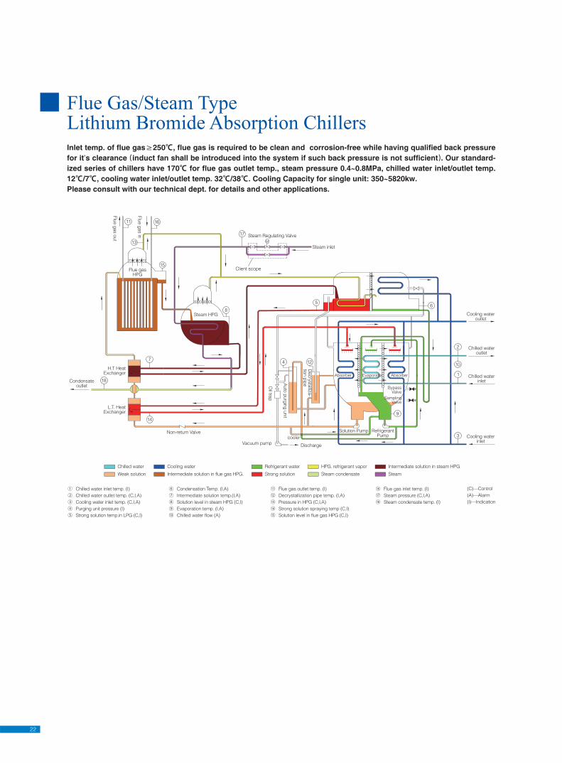
Inlet temp. of flue gas≥250℃, flue gas is required to be clean and corrosion-free while having qualified back pressure for it’s clearance induct fan shall be introduced into the system if such back pressure is not sufficient . Our standard-ized series of chillers have 170℃ for flue gas outlet temp., steam pressure 0.4~0.8MPa, chilled water inlet/outlet temp. 12℃/7℃, cooling water inlet/outlet temp. 32℃/38℃. Cooling Capacity for single unit: 350~5820kw.Please consult with our technical dept. for details and other applications.
Flue Gas/Steam TypeLithium Bromide Absorption Chillers
L.T. HeatExchanger
Non-return Valve
Vacuum pump
cooler
Discharge
Oil tra
p
Auto
purg
ing
unit
Decry
sta
lliza-
tion p
ipe
Solution Pump RefrigerantPump
BypassValve
SamplingValve
Cooling waterinlet
Condensateoutlet
Steam inlet
Client scope
H.T HeatExchanger
Steam HPG
Flue gasHPG
Flu
e g
as o
ut
AbsorberAbsorber Evaporator
Chilled wateroutlet
Chilled waterinlet
Cooling wateroutlet
Flu
e g
as in Steam Regulating Valve
Chilled water
Weak solution
Cooling water
Intermediate solution in flue gas HPG.
Refrigerant water
Strong solution
HPG. refrigerant vapor
Steam condensate
Intermediate solution in steam HPG
Steam
① Chilled water inlet temp. (I)
② Chilled water outlet temp. (C,I,A)
③ Cooling water inlet temp. (C,I,A)
④ Purging unit pressure (I)
⑤ Strong solution temp.in LPG (C,I)
⑥ Condensation Temp. (I,A)
⑦ Intermediate solution temp.(I,A)
⑧ Solution level in steam HPG (C,I)
⑨ Evaporation temp. (I,A)
⑩ Chilled water flow (A)
⑪ Flue gas outlet temp. (I)
⑫ Decrystallization pipe temp. (I,A)
⑬ Pressure in HPG (C,I,A)
⑭ Strong solution spraying temp (C,I)
⑮ Solution level in flue gas HPG (C,I)
⑯ Flue gas inlet temp. (I)
⑰ Steam pressure (C,I,A)
⑱ Steam condensate temp. (I)
(C)—Control
(A)—Alarm
(I)—Indication
23
Cooler
Samplingvalve
Bypassvalve
Solution pump
LPG
Absorber Evaporator Absorber
Flue-gas HPG
3-ways regulating valve
Heat sourceHot-water
Heat sourceHot-water
flue-gasout
flue-gasin
Condenser
Cooling waterout
Cooling waterin
Refrigerant pump
Decry
sta
-liz
atio
n p
ipin
g
Auto
purg
ing
unit
Non-return valve
Vacuum pump Discharge
Oil tra
p
L.T. heatexchanger
H.T. heatexchangerChilled water
Weak solution
Cooling water
Intermediate solution
Refrigerant water
Strong solution
HPG refrigerant vapor
Hot water
Refrigerant vapor
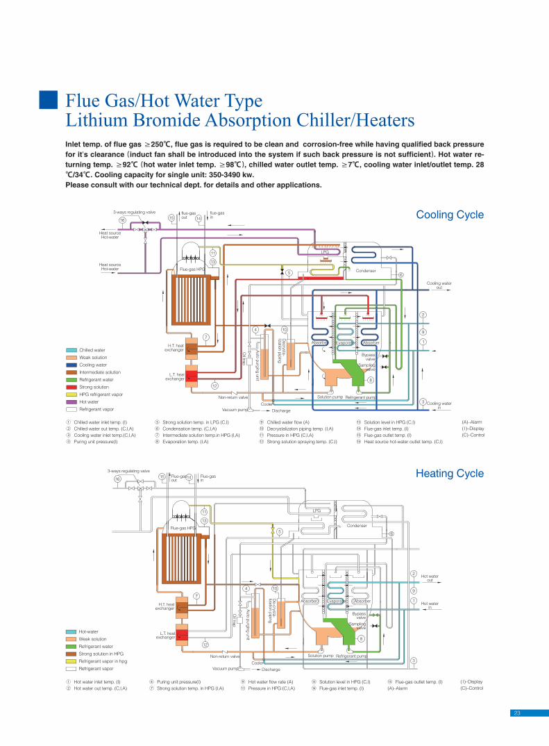
① Chilled water inlet temp. (I)
② Chilled water out temp. (C,I,A)
③ Cooling water inlet temp.(C,I,A)
④ Puring unit pressure(I)
⑤ Strong solution temp. in LPG (C,I)
⑥ Condensation temp. (C,I,A)
⑦ Intermediate solution temp.in HPG (I,A)
⑧ Evaporation temp. (I,A)
⑨ Chilled water flow (A)
⑩ Decrystalizaton piping temp. (I,A)
⑪ Pressure in HPG (C,I,A)
⑫ Strong solution spraying temp. (C,I)
⑬ Solution level in HPG (C,I)
⑭ Flue-gas inlet temp. (I)
⑮ Flue-gas outlet temp. (I)
⑯ Heat source hot-water outlet temp. (C,I)
(A)–Alarm
(I)–Display
(C)–Control
Samplingvalve
Bypassvalve
Hot waterout
Hot waterin
3-ways regulating valve
Flue-gas HPG
L.T. heatexchanger
H.T. heatexchanger
Flue-gasin
Flue-gasout
Condenser
LPG
Absorber AbsorberEvaporator
Oil tra
p
Auto
purg
ing
unit
De-c
rysta
-liz
atio
n p
ipin
g
DischargeVacuum pump
Non-return valve Refrigerant pumpSolution pump
Cooler
① Hot water inlet temp. (I)
② Hot water out temp. (C,I,A)
Hot-water
Weak solution
Refrigerant water
Strong solution in HPG
Refrigerant vapor in hpg
Refrigerant vapor
④ Puring unit pressure(I)
⑦ Strong solution temp. in HPG (I,A)
⑨ Hot water flow rate (A)
⑪ Pressure in HPG (C,I,A)
⑬ Solution level in HPG (C,I)
⑭ Flue-gas inlet temp. (I)
⑮ Flue-gas outlet temp. (I)
(A)–Alarm
(I)–Display
(C)–Control
Flue Gas/Hot Water TypeLithium Bromide Absorption Chiller/HeatersInlet temp. of flue gas ≥250℃, flue gas is required to be clean and corrosion-free while having qualified back pressure for it’s clearance induct fan shall be introduced into the system if such back pressure is not sufficient . Hot water re-turning temp. ≥92℃ hot water inlet temp. ≥98℃ , chilled water outlet temp. ≥7℃, cooling water inlet/outlet temp. 28℃/34℃. Cooling capacity for single unit: 350-3490 kw.Please consult with our technical dept. for details and other applications.
Cooling Cycle
Heating Cycle
24
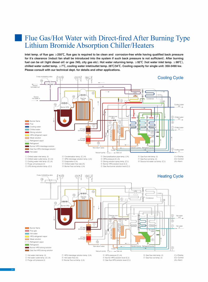
Flue Gas/Hot Water with Direct-fi red After Burning Type Lithium Bromide Absorption Chiller/HeatersInlet temp. of flue gas ≥250℃, flue gas is required to be clean and corrosion-free while having qualified back pressure for it’s clearance induct fan shall be introduced into the system if such back pressure is not sufficient . After burning fuel can be oil light diesel oil or gas NG, city gas etc . Hot water returning temp. ≥92℃ hot water inlet temp. ≥98℃ , chilled water outlet temp. ≥7℃, cooling water inlet/outlet temp. 28℃/34℃. Cooling capacity for single unit: 350-3490 kw.Please consult with our technical dept. for details and other applications.
Samplingvale
Non-return valve
Cooler
Gas outVacuum pump
Solution pump Refrigerant pump
Cooling waterin
Burner HPG
Flu
e o
ut
HT heatexchanger
Oil tra
p
Auto
purg
e u
nit
Auto
decry
sta
-lliz
atio
n p
ipe
change-overvalve
Gas flueHPG
Absorber Evaporator
By passvalve
Absorber Chilled waterin
Chilled waterout
Cooling waterout
Gas flu
e in
Sourcehot water in
Sourcehot water out
3 way modulating valve
Flu
e o
ut
Condensor
LPG
LT heatexchanger
Burner flame
Flue
Cooling water
Chilled water
Strong solution
HPG refrigerant vapor
Weak solution
Refrigerant vapor
Refrigerant
Burner HPG interstage solution
Gas flue HPG interstage solution
Hot water
① Chilled water inlet temp. (I)
② Chilled water outlet temp. (C,I,A)
③ Cooling water inlet temp. (C,I,A)
④ Purge unit pressure (I)
⑤ LPG strong solution temp. (C,I)
⑥ Condensation temp. (C,I,A)
⑦ HPG interstage solution temp. (I,A)
⑧ Evaporation (I,A)
⑨ Chilled water flow rate (A)
⑩ Burner flue out temp. (I,A)
⑪ Decrystallization pipe temp. (I,A)
⑫ HPG pressure (C,I,A)
⑬ Strong solution spray temp. (C,I)
⑭ Burner HPG solution level (C,I)
⑮ Gas flue burner solution level (C,I)
⑯ Gas flue inlet temp. (I)
⑰ Gas flue out temp. (I)
⑱ Source hot water out temp. (C,I)
( I )−Display
(C)−Control
(A)−Alarm
Auto
purg
e u
nit
Auto
decry
sta
-lliz
atio
n p
ipe
Burner HPG
Gas flueHPG
Solution pump Refrigerant pump
Absorber Evaporator
By passvalve
Absorber Hot waterin
Hot waterout
7
Oil tra
p
Change-overvalve
Flu
e o
ut
Gas flu
e in
3 way modulating valve
Flu
e o
ut
Condensor
LPG
Non-return valve
Cooler
Gas outVacuum pump
HT heatexchanger
LT heatexchanger
Burner flame
Flue gas
Hot water
HPG refrigerant vapor
Weak solution
Refrigerant vapor
Refrigerant
Burner HPG strong solution
Gas flue HPG strong solution
① Hot water inlet temp. (I)
② Hot water outlet temp. (C,I,A)
④ Purge unit pressure (I)
⑦ HPG interstage solution temp. (I,A)
⑨ Hot water flow (A)
⑩ Burner flue out temp. (I,A)
⑫ HPG pressure (C,I,A)
⑭ Burner HPG solution level (C,I)
⑮ Gas flue HPG solution level (C,I)
⑯ Gas flue inlet temp. (I)
⑰ Gas flue out temp. (I)
( I )−Display
(C)−Control
(A)−Alarm
Cooling Cycle
Heating Cycle
25
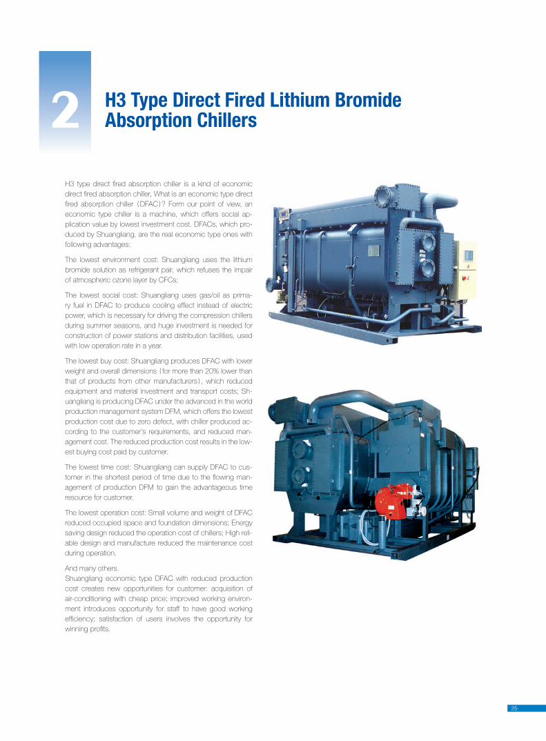
H3 Type Direct Fired Lithium Bromide Absorption Chillers2
H3 type direct fi red absorption chiller is a kind of economic
direct fi red absorption chiller, What is an economic type direct
fi red absorption chiller DFAC ? Form our point of view, an
economic type chiller is a machine, which offers social ap-
plication value by lowest investment cost. DFACs, which pro-
duced by Shuangliang, are the real economic type ones with
following advantages:
The lowest environment cost: Shuangliang uses the lithium
bromide solution as refrigerant pair, which refuses the impair
of atmospheric ozone layer by CFCs;
The lowest social cost: Shuangliang uses gas/oil as prima-
ry fuel in DFAC to produce cooling effect instead of electric
power, which is necessary for driving the compression chillers
during summer seasons, and huge investment is needed for
construction of power stations and distribution facilities, used
with low operation rate in a year.
The lowest buy cost: Shuangliang produces DFAC with lower
weight and overall dimensions for more than 20% lower than
that of products from other manufacturers , which reduced
equipment and material investment and transport costs; Sh-
uangliang is producing DFAC under the advanced in the world
production management system DFM, which offers the lowest
production cost due to zero defect, with chiller produced ac-
cording to the customer’s requirements, and reduced man-
agement cost. The reduced production cost results in the low-
est buying cost paid by customer.
The lowest time cost: Shuangliang can supply DFAC to cus-
tomer in the shortest period of time due to the fl owing man-
agement of production DFM to gain the advantageous time
resource for customer.
The lowest operation cost: Small volume and weight of DFAC
reduced occupied space and foundation dimensions; Energy
saving design reduced the operation cost of chillers; High reli-
able design and manufacture reduced the maintenance cost
during operation.
And many others.
Shuangliang economic type DFAC with reduced production
cost creates new opportunities for customer: acquisition of
air-conditioning with cheap price; improved working environ-
ment introduces opportunity for staff to have good working
effi ciency; satisfaction of users involves the opportunity for
winning profi ts.
26
Performance Parameters Working Principle
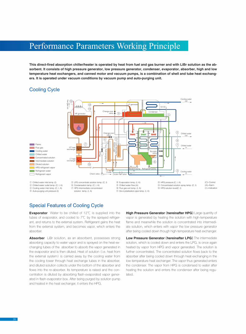
This direct-fired absorption chiller/heater is operated by heat from fuel and gas burner and with LiBr solution as the ab-sorbent. It consists of high pressure generator, low pressure generator, condenser, evaporator, absorber, high and low temperature heat exchangers, and canned motor and vacuum pumps, is a combination of shell and tube heat exchang-ers. It is operated under vacuum conditions by vacuum pump and auto-purging unit.
Special Features of Cooling Cycle
Cooling Cycle
Evaporator Water to be chilled of 12℃ is supplied into the
tubes of evaporator, and cooled to 7℃ by the sprayed refriger-
ant, and returns to the external system. Refrigerant gains the heat
from the external system, and becomes vapor, which enters the
absorber.
Absorber LiBr solution, as an absorbent, possesses strong
absorbing capacity to water vapor and is sprayed on the heat-ex-
changing tubes of the absorber to absorb the vapor generated in
the evaporator and is then diluted. Heat of solution i.e. heat from
the external system is carried away by the cooling water from
the cooling tower through heat exchange tubes in the absorber,
and diluted solution collects under the bottom of the absorber and
fl ows into the re-absorber. Its temperature is raised and the con-
centration is diluted by absorbing fl ash-evaporated vapor gener-
ated in fl ash-evaporator box. After being purged by solution pump
and heated in the heat exchanger, it enters the HPG.
High Pressure Generator hereinafter HPG Large quantity of
vapor is generated by heating the solution with high-temperature
fl ame and meanwhile the solution is concentrated into intermedi-
ate solution, which enters with vapor the low pressure generator
after being cooled down though high-temperature heat exchanger.
Low Pressure Generator hereinafter LPG The intermediate
solution, which is cooled down and enters the LPG, is once again
heated by vapor from HPG and vapor generated. The solution is
further concentrated. The concentrated solution fl ows back to the
absorber after being cooled down through heat-exchanging in the
low-temperature heat exchanger. The vapor thus generated enters
the condenser. The vapor from HPG is condensed to water after
heating the solution and enters the condenser after being regu-
lated.
① Chilled water inlet temp. (I)
② Chilled water outlet temp. (C, I, A)
③ Cooling water inlet temp. (C, I, A)
④ Auto-purging unit pressure (I)
⑤ LPG concentrate solution temp. (C, I)
⑥ Condensation temp. (C, I, A)
⑦ HPG intermediate concentrated
solution temp. (I, A)
⑧ Evaporation temp. (I, A)
⑨ Chilled water flow (A)
⑩ Flue gas exit temp. (I, A)
⑪ De-crystallization pipe temp. (I, A)
⑫ HPG pressure (C, I, A)
⑬ Concentrated solution spray temp. (C, I)
⑭ HPG solution level(C, I)
(C)−Control
(A)−Alarm
(I)−Indication
HT heatexchanger
LT heatexchanger
CoolerCooler inlet valve
Oil tra
p
Auto
purg
ing
unit
Auto
decry
sta
-lliz
atio
n p
ipe
Absorber AbsorberEvaporator
Solution pump Refrigerant pump
By-passvalve
Samplingvalve
Cooling waterin
Chilled waterin
Chilled waterout
Cooling waterout
flue g
as o
ut
HP generator
Change-overvalve
Change-overvalve
LP generator
Condenser
6
Check valve
Flame
Flue gas
Cooling water
Chilled water
Concentrated solution
Intermediate solution
Diluted solution
HPG refrigerant vapor
Refrigerant water
Refrigerant vapor
27
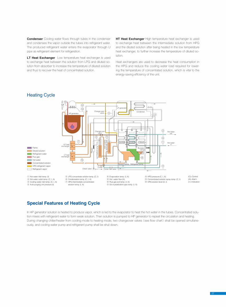
In HP generator solution is heated to produce vapor, which is led to the evaporator to heat the hot water in the tubes. Concentrated solu-
tion mixes with refrigerant water to form weak solution. Then solution is pumped to HP generator to repeat the circulation and heating.
During changing chiller/heater from cooling mode to heating mode, two changeover valves see fl ow chart shall be opened simultane-
ously, and cooling water pump and refrigerant pump shall be shut down.
Special Features of Heating Cycle
Heating Cycle
Condenser Cooling water fl ows through tubes in the condenser
and condenses the vapor outside the tubes into refrigerant water.
The produced refrigerant water enters the evaporator through U
pipe as refrigerant element for refrigeration.
LT Heat Exchanger Low temperature heat exchanger is used
to exchange heat between the solution from LPG and diluted so-
lution from absorber to increase the temperature of diluted solution
and thus to recover the heat of concentrated solution.
HT Heat Exchanger High temperature heat exchanger is used
to exchange heat between the intermediate solution from HPG
and the diluted solution after being heated in the low temperature
heat exchanger, to further increase the temperature of diluted so-
lution.
Heat exchangers are used to decrease the heat consumption in
the HPG and reduce the cooling water load required for lower-
ing the temperature of concentrated solution, which is vital to the
energy-saving effi ciency of the unit.
① Hot water inlet temp. (I)
② Hot water outlet temp. (C, I, A)
③ Cooling water inlet temp. (C, I, A)
④ Auto-purging unit pressure (I)
⑤ LPG concentrate solution temp. (C, I)
⑥ Condensation temp. (C, I, A)
⑦ HPG intermediate concentrated
solution temp. (I, A)
⑧ Evaporation temp. (I, A)
⑨ Hot water flow (A)
⑩ Flue gas exit temp. (I, A)
⑪ De-crystallization pipe temp. (I, A)
⑫ HPG pressure (C, I, A)
⑬ Concentrated solution spray temp. (C, I)
⑭ HPG solution level (C, I)
(C)−Control
(A)−Alarm
(I)−Indication
HT heatexchanger
LT heatexchanger
CoolerCooler inlet valve
Oil tra
p
Auto
purg
ing
unit
Auto
decry
sta
-lliz
atio
n p
ipe
Absorber AbsorberEvaporator
Solution pump Refrigerant pump
By-passvalve
Samplingvalve
Hot waterin
Hot waterout
flue g
as e
xit
HP generator
Change-overvalve
Change-overvalve
LP generator
Condenser
6
Check valve
Flame
Diluted solution
Refrigerant water
Flue gas
Hot water
Concentrated solution
HPG refrigerant vapor
Refrigerant vapor
28
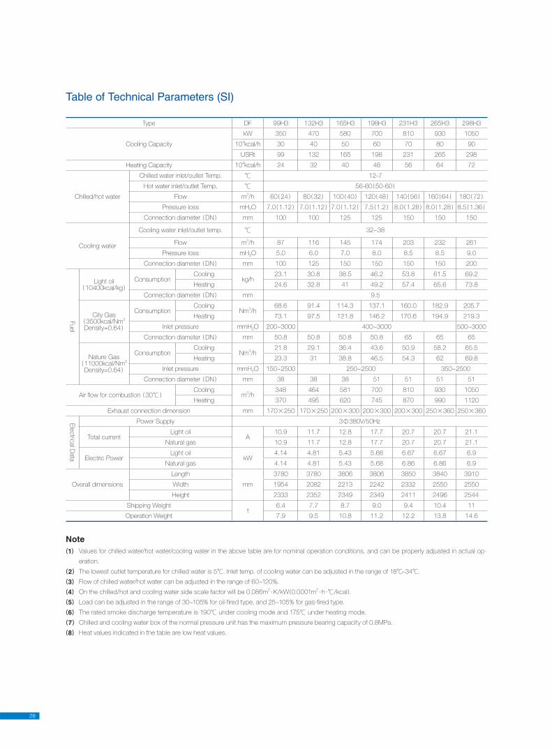
Table of Technical Parameters (SI)
Note1 Values for chilled water/hot water/cooling water in the above table are for nominal operation conditions, and can be properly adjusted in actual op-
eration.
2 The lowest outlet temperature for chilled water is 5℃. Inlet temp. of cooling water can be adjusted in the range of 18℃~34℃.
3 Flow of chilled water/hot water can be adjusted in the range of 60~120%.
4 On the chilled/hot and cooling wa ter side scale factor will be 0.086m2·K/kW 0.0001m
2·h ·℃/kcal .
5 Load can be adjusted in the range of 30~105% for oil-fired type, and 25~105% for gas-fired type.
6 The rated smoke discharge tem per a ture is 190℃ under cooling mode and 175℃ un der heating mode.
7 Chilled and cooling water box of the nor mal pressure unit has the max i mum pres sure bearing capacity of 0.8MPa.
8 Heat values indicated in the table are low heat values.
Type DF 99H3 132H3 165H3 198H3 231H3 265H3 298H3
Cooling Capacity
kW 350 470 580 700 810 930 1050
104kcal/h 30 40 50 60 70 80 90
USRt 99 132 165 198 231 265 298
Heating Capacity 104kcal/h 24 32 40 48 56 64 72
Chilled/hot water
Chilled water inlet/outlet Temp. ℃ 12-7
Hot water inlet/outlet Temp. ℃ 56-60 50-60
Flow m3/h 60 24 80 32 100 40 120 48 140 56 160 64 180 72
Pressure loss mH2O 7.0 1.12 7.0 1.12 7.0 1.12 7.5 1.2 8.0 1.28 8.0 1.28 8.5 1.36
Connection diameter DN mm 100 100 125 125 150 150 150
Cooling water
Cooling water inlet/outlet temp. ℃ 32~38
Flow m3/h 87 116 145 174 203 232 261
Pressure loss mH2O 5.0 6.0 7.0 8.0 8.5 8.5 9.0
Connection diameter DN mm 100 125 150 150 150 150 200
Fuel
Light oil10400kcal/kg
ConsumptionCooling
kg/h23.1 30.8 38.5 46.2 53.8 61.5 69.2
Heating 24.6 32.8 41 49.2 57.4 65.6 73.8
Connection diameter DN mm 9.5
City Gas3500kcal/Nm
3
Density=0.64
ConsumptionCooling
Nm3/h
68.6 91.4 114.3 137.1 160.0 182.9 205.7
Heating 73.1 97.5 121.8 146.2 170.6 194.9 219.3
Inlet pressure mmH2O 200~3000 400~3000 500~3000
Connection diameter DN mm 50.8 50.8 50.8 50.8 65 65 65
Nature Gas11000kcal/Nm
3
Density=0.64
ConsumptionCooling
Nm3/h
21.8 29.1 36.4 43.6 50.9 58.2 65.5
Heating 23.3 31 38.8 46.5 54.3 62 69.8
Inlet pressure mmH2O 150~2500 250~2500 350~2500
Connection diameter DN mm 38 38 38 51 51 51 51
Air fl ow for combustion 30℃Cooling
m3/h
348 464 581 700 810 930 1050
Heating 370 495 620 745 870 990 1120
Exhaust connection dimension mm 170×250 170×250 200×300 200×300 200×300 250×360 250×360
Ele
ctric
al D
ata
Power Supply 3Ф380V/50Hz
Total currentLight oil
A10.9 11.7 12.8 17.7 20.7 20.7 21.1
Natural gas 10.9 11.7 12.8 17.7 20.7 20.7 21.1
Electric PowerLight oil
kW4.14 4.81 5.43 5.68 6.67 6.67 6.9
Natural gas 4.14 4.81 5.43 5.68 6.86 6.86 6.9
Overall dimensions
Length
mm
3780 3780 3806 3806 3850 3840 3910
Width 1954 2082 2213 2242 2332 2550 2550
Height 2333 2352 2349 2349 2411 2496 2544
Shipping Weightt
6.4 7.7 8.7 9.0 9.4 10.4 11
Operation Weight 7.9 9.5 10.8 11.2 12.2 13.8 14.6
29
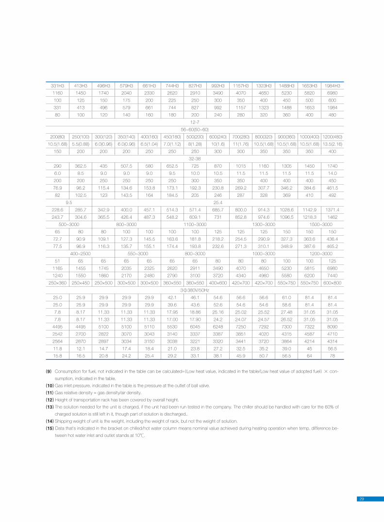
9 Consumption for fuel, not indicated in the table can be calculated= Low heat value, indicated in the table/Low heat value of adopted fuel × con-
sumption, indicated in the table.
10 Gas inlet pressure, indicated in the table is the pressure at the outlet of ball valve.
11 Gas relative density = gas density/air density.
12 Height of transportation rack has been covered by overall height.
13 The solution needed for the unit is charged, if the unit had been run tested in the company. The chiller should be handled with care for the 60% of
charged solution is still left in it, though part of solution is discharged..
14 Shipping weight of unit is the weight, including the weight of rack, but not the weight of solution.
15 Data that’s indicated in the bracket on chilled/hot water column means nominal value achieved during heating operation when temp. difference be-
tween hot water inlet and outlet stands at 10℃.
331H3 413H3 496H3 579H3 661H3 744H3 827H3 992H3 1157H3 1323H3 1488H3 1653H3 1984H3
1160 1450 1740 2040 2330 2620 2910 3490 4070 4650 5230 5820 6980
100 125 150 175 200 225 250 300 350 400 450 500 600
331 413 496 579 661 744 827 992 1157 1323 1488 1653 1984
80 100 120 140 160 180 200 240 280 320 360 400 480
12-7
56~60(50~60)
200(80) 250(100) 300(120) 350(140) 400(160) 450(180) 500(200) 600(240) 700(280) 800(320) 900(360) 1000(400) 1200(480)
10.5(1.68) 5.5(0.88) 6.0(0.96) 6.0(0.96) 6.5(1.04) 7.0(1.12) 8(1.28) 10(1.6) 11(1.76) 10.5(1.68) 10.5(1.68) 10.5(1.68) 13.5(2.16)
150 200 200 200 250 250 250 300 300 350 350 350 400
32-38
290 362.5 435 507.5 580 652.5 725 870 1015 1160 1305 1450 1740
6.0 8.5 9.0 9.0 9.0 9.5 10.0 10.5 11.5 11.5 11.5 11.5 14.0
200 200 250 250 250 250 300 350 350 400 400 400 450
76.9 96.2 115.4 134.6 153.8 173.1 192.3 230.8 269.2 307.7 346.2 384.6 461.5
82 102.5 123 143.5 164 184.5 205 246 287 328 369 410 492
9.5 25.4
228.6 285.7 342.9 400.0 457.1 514.3 571.4 685.7 800.0 914.3 1028.6 1142.9 1371.4
243.7 304.6 365.5 426.4 487.3 548.2 609.1 731 852.8 974.6 1096.5 1218.3 1462
500~3000 800~3000 1100~3000 1300~3000 1500~3000
65 80 80 100 100 100 100 125 125 125 150 150 150
72.7 90.9 109.1 127.3 145.5 163.6 181.8 218.2 254.5 290.9 327.3 363.6 436.4
77.5 96.9 116.3 135.7 155.1 174.4 193.8 232.6 271.3 310.1 348.9 387.6 465.2
400~2500 550~3000 800~3000 1000~3000 1200~3000
51 65 65 65 65 65 65 80 80 80 100 100 125
1165 1455 1745 2035 2325 2620 2911 3490 4070 4650 5230 5815 6980
1240 1550 1860 2170 2480 2790 3100 3720 4340 4960 5580 6200 7440
250×360 250×450 250×500 300×500 300×500 360×550 360×550 400×600 420×700 420×700 550×750 550×750 600×800
3Ф380V/50Hz
25.0 25.9 29.9 29.9 29.9 42.1 46.1 54.6 56.6 56.6 61.0 81.4 81.4
25.0 25.9 29.9 29.9 29.9 39.6 43.6 52.6 54.6 54.6 58.6 81.4 81.4
7.8 8.17 11.33 11.33 11.33 17.95 18.86 25.16 25.02 25.52 27.48 31.05 31.05
7.8 8.17 11.33 11.33 11.33 17.00 17.90 24.2 24.07 24.57 26.52 31.05 31.05
4495 4495 5100 5100 5110 5530 6045 6248 7250 7292 7300 7322 8090
2542 2700 2822 3070 3043 3140 3337 3387 3851 4020 4315 4587 4710
2564 2870 2897 3034 3150 3038 3221 3320 3441 3720 3864 4214 4314
11.8 12.1 14.7 17.4 18.4 21.0 23.8 27.2 32.5 35.2 39.0 45 56.5
15.8 16.5 20.8 24.2 25.4 29.2 33.1 38.1 45.9 50.7 56.5 64 78
30
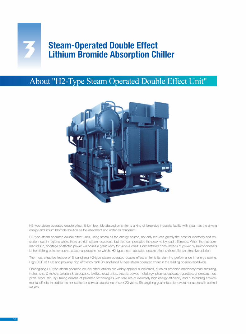
3 Steam-Operated Double EffectLithium Bromide Absorption Chiller
H2-type steam operated double effect lithium bromide absorption chiller is a kind of large-size industrial facility with steam as the driving
energy and lithium bromide solution as the absorbent and water as refrigerant.
H2-type steam operated double effect units, using steam as the energy source, not only reduces greatly the cost for electricity and op-
eration fees in regions where there are rich steam resources, but also compensates the peak-valley load difference. When the hot sum-
mer rolls in, shortage of electric power will poses a great worry for various cities. Concentrated consumption of power by air-conditioners
is the sticking point for such a seasonal problem, for which, H2-type steam operated double effect chillers offer an attractive solution.
The most attractive feature of Shuangliang H2-type steam operated double effect chiller is its stunning performance in energy saving.
High COP of 1.33 and provenly high effi ciency rank Shuangliang H2-type steam operated chiller in the leading position worldwide.
Shuangliang H2-type steam operated double effect chillers are widely applied in industries, such as precision machinery manufacturing,
instruments & meters, aviation & aerospace, textiles, electronics, electric power, metallurgy, pharmaceuticals, cigarettes, chemicals, hos-
pitals, food, etc. By utilizing dozens of patented technologies with features of extremely high energy effi ciency and outstanding environ-
mental effects, in addition to her customer service experience of over 20 years, Shuangliang guarantees to reward her users with optimal
returns.
About "H2-Type Steam Operated Double Effect Unit"
31
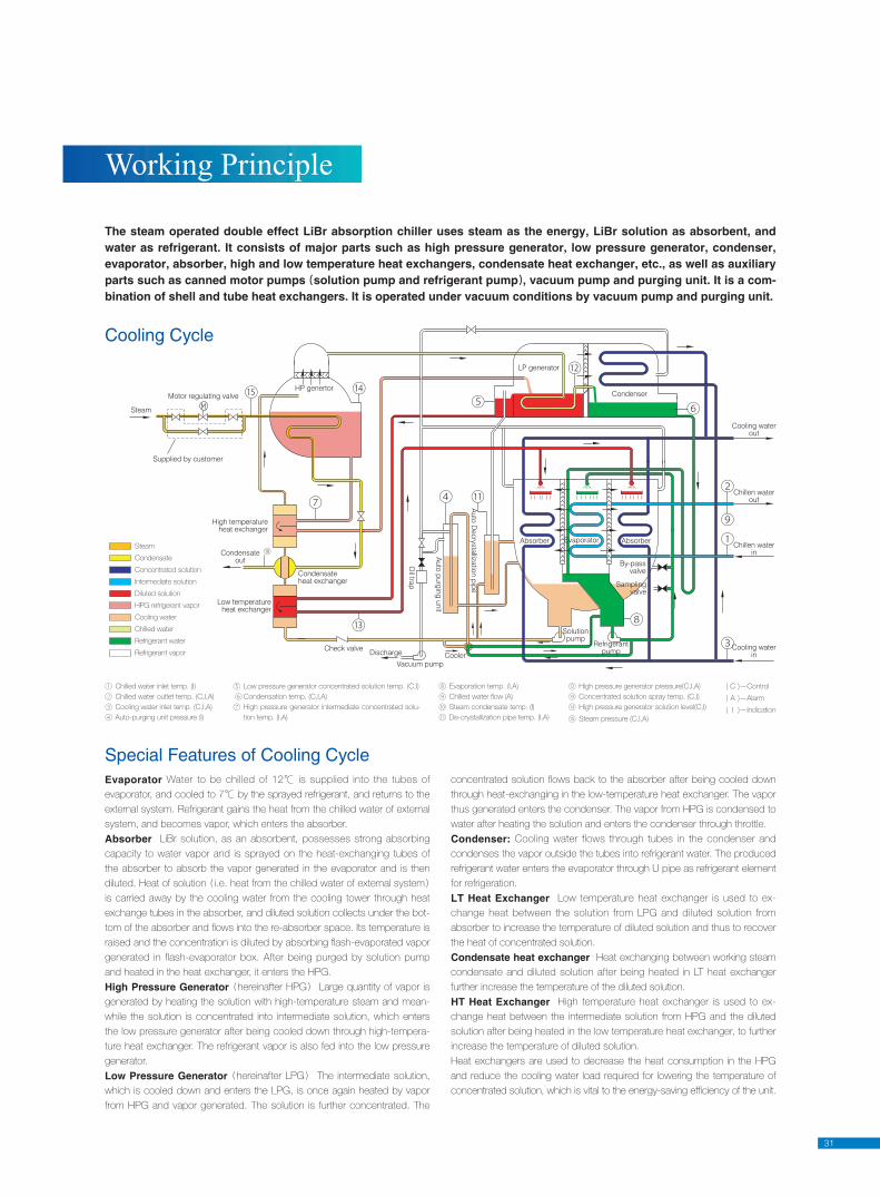
The steam operated double effect LiBr absorption chiller uses steam as the energy, LiBr solution as absorbent, and water as refrigerant. It consists of major parts such as high pressure generator, low pres sure generator, condenser, evaporator, absorber, high and low tem per a ture heat exchangers, condensate heat exchanger, etc., as well as auxiliary parts such as canned motor pumps solution pump and refrigerant pump , vacuum pump and purging unit. It is a com-bination of shell and tube heat exchangers. It is operated under vacuum conditions by vacuum pump and purg ing unit.
Evaporator Water to be chilled of 12℃ is supplied into the tubes of
evaporator, and cooled to 7℃ by the sprayed refrigerant, and returns to the
external system. Re frig er ant gains the heat from the chilled water of ex ter nal
system, and be comes vapor, which enters the absorber.
Absorber LiBr solution, as an absorbent, possesses strong absorbing
ca pac i ty to wa ter vapor and is sprayed on the heat-exchanging tubes of
the ab sorb er to absorb the vapor generated in the evaporator and is then
diluted. Heat of solution i.e. heat from the chilled water of external system
is car ried away by the cooling water from the cooling tower through heat
ex change tubes in the absorber, and diluted solution col lects under the bot-
tom of the absorber and fl ows into the re-absorber space. Its tem per a ture is
raised and the con cen tra tion is diluted by ab sorb ing fl ash-evaporated vapor
generated in flash-evaporator box. After being purged by solution pump
and heated in the heat exchanger, it enters the HPG.
High Pressure Generator hereinafter HPG Large quantity of va por is
gen er at ed by heating the solution with high-tem per a ture steam and mean-
while the solution is con cen trat ed into intermediate solution, which enters
the low pressure generator after be ing cooled down through high-tem per a-
ture heat exchanger. The refrigerant vapor is also fed into the low pressure
generator.
Low Pressure Generator hereinafter LPG The intermediate solution,
which is cooled down and enters the LPG, is once again heat ed by vapor
from HPG and vapor generated. The solution is further concentrated. The
con cen trat ed solution fl ows back to the ab sorb er af ter being cooled down
through heat-exchanging in the low-tem per a ture heat exchanger. The va por
thus gen er at ed enters the condenser. The vapor from HPG is con densed to
water after heating the solution and enters the condenser through throttle.
Condenser: Cooling water flows through tubes in the condenser and
condenses the vapor outside the tubes into refrigerant water. The produced
refrigerant water enters the evaporator through U pipe as refrigerant element
for refrigeration.
LT Heat Exchanger Low temperature heat exchanger is used to ex-
change heat be tween the solution from LPG and diluted solution from
absorber to increase the tem per a ture of diluted solution and thus to recover
the heat of concentrated solution.
Condensate heat exchanger Heat exchanging between working steam
con den sate and diluted solution after being heated in LT heat exchanger
fur ther increase the tem per a ture of the diluted solution.
HT Heat Exchanger High temperature heat exchanger is used to ex-
change heat be tween the intermediate solution from HPG and the di lut ed
solution after being heated in the low temperature heat exchanger, to further
in crease the tem per a ture of diluted solution.
Heat exchangers are used to decrease the heat consumption in the HPG
and reduce the cooling water load required for lowering the tem per a ture of
con cen trat ed solution, which is vital to the en er gy-saving effi ciency of the unit.
Special Features of Cooling Cycle
Work ing Prin ci ple
Cooling Cycle
Motor regulating valve
Steam
Supplied by customer
High temperatureheat exchanger
Low temperatureheat exchanger
Condensateheat exchanger
Condensateout
Check valve Discharge
Oil trap
Auto purging un it
Auto D
ecrystallization pipe
Vacuum pumpCooler
HP genertor
LP generator
Condenser
Solutionpump
Refrigerantpump
Samplingvalve
By-passvalve
AbsorberAbsorber Evaporator
Cooling waterin
Chillen waterin
Chillen waterout
Cooling waterout
⑩Steam
Condensate
Concentrated solution
Intermediate solution
Diluted solution
HPG refrigerant vapor
Cooling water
Chilled water
Refrigerant water
Refrigerant vapor
① Chilled water inlet temp. (I)
② Chilled water outlet temp. (C,I,A)
③ Cooling water inlet temp. (C,I,A)
④ Auto-purging unit pressure (I)
( C )—Control
( A )—Alarm
( I )—Indication
⑤ Low pressure generator concentrated solution temp. (C,I)
⑥ Condensation temp. (C,I,A)
⑦ High pressure generator intermediate concentrated solu-
tion temp. (I,A)
⑧ Evaporation temp. (I,A)
⑨ Chilled water fl ow (A)
⑩ Steam condensate temp. (I)
⑪ De-crystallization pipe temp. (I,A)
⑫ High pressure generator pressure(C,I,A)
⑬ Concentrated solution spray temp. (C,I)
⑭ High pressure generator solution level(C,I)
⑮ Steam pressure (C,I,A)
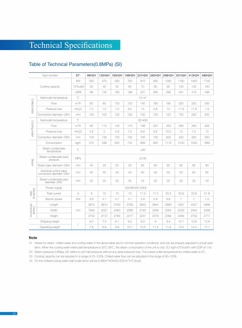
32
Table of Technical Parameters(0.8MPa) (SI)
Note1 Values for steam, chilled water and cooling water in the above table are for nominal operation conditions, and can be properly adjusted in actual oper-
ation. When the cooling water inlet/outlet temperature is 30℃/36℃, the steam consumption of the unit is only 12.2 kg/h· 104kcal/h with COP at 1.43.
2 Steam pressure 0.8Mpa G refers to unit inlet pressure without any valve pressure loss. The lowest outlet temperature for chilled water is 5℃.
3 Cooling capacity can be adjusted in a range of 20~100%. Chilled water fl ow can be adjusted in the range of 60~120%
4 On the chilled/cooling water side scale factor will be 0.086m2·K/kW 0.0001m
2·h·℃/kcal .
Type number ST- 99H2H 132H2H 165H2H 198H2H 231H2H 265H2H 298H2H 331H2H 413H2H 496H2H
Cooling capacity
KW 350 470 580 700 810 930 1050 1160 1450 1740
104kcal/h 30 40 50 60 70 80 90 100 125 150
USRt 99 132 165 198 231 265 298 331 413 496
Chille
d w
ate
r
Inlet/outlet temperature ℃ 12→7
Flow m3/h 60 80 100 120 140 160 180 200 250 300
Pressure loss mH2O 7.0 7.0 7.0 8.5 10 9.8 10 11.8 11.8 7.9
Connection diameter DN mm 100 100 125 125 150 150 150 150 200 200
Coolin
g w
ate
r
Inlet/outlet temperature ℃ 32→38
Flow m3/h 85 113 142 170 198 227 255 283 354 425
Pressure loss mH2O 4.2 5 5.8 7.5 8.9 9.2 10.5 12 7.5 10
Connection diameter DN mm 100 125 150 150 150 150 200 200 200 250
Ste
am
Consumption kg/h 372 496 620 744 868 992 1116 1240 1550 1860
Steam condensatetemperature ℃ ≤95
Steam condensate backpressure
MPa ≤0.05
Steam pipe diameter DN mm 40 50 50 50 65 65 65 65 80 80
Electrical control valveconnection diameter DN
mm 40 40 40 40 40 50 50 50 65 65
Steam condensate pipediameter DN
mm 25 25 25 25 25 32 32 32 32 40
Ele
ctric
al
data
Power supply 3Φ380VAC-50Hz
Total current A 8 10 10 10 17.3 17.3 20.3 20.8 20.8 21.8
Electric power KW 3.8 4.1 4.1 4.1 5.9 5.9 6.8 7 7 7.2
Ove
rall
dim
ensio
ns
Length
mm
3810 3810 3790 3790 3820 3840 2890 4357 4357 4895
Width 1942 2027 2060 2060 2183 2308 2355 2332 2450 2558
Height 2152 2170 2169 2217 2231 2316 2364 2384 2702 2717
Shipping weightt
6.5 7.3 8.1 8.2 8.3 9 9.4 10.1 10.8 12.8
Operating weight 7.8 8.9 9.9 10.1 10.3 11.4 11.9 13.4 14.4 17.1
Tech ni cal Spec i fi ca tions
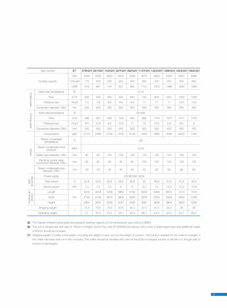
33
Type number ST- 579H2H 661H2H 744H2H 827H2H 992H2H 1157H2H 1323H2H 1488H2H 1653H2H 1984H2H
Cooling capacity
KW 2040 2330 2620 2910 3490 4070 4650 5230 5820 6980
104kcal/h 175 200 225 250 300 350 400 450 500 600
USRt 579 661 744 827 992 1157 1323 1488 1653 1984
Chille
d w
ate
r
Inlet/outlet temperature ℃ 12→7
Flow m3/h 350 400 450 500 600 700 800 900 1000 1200
Pressure loss mH2O 7.5 7.8 8.6 9.9 9.5 11 11 11 13.5 13.5
Connection diameter DN mm 200 250 250 250 300 300 350 350 350 400
Coolin
g w
ate
r
Inlet/outlet temperature ℃ 32→38
Flow m3/h 496 567 638 709 850 992 1134 1275 1417 1700
Pressure loss mH2O 9.5 10.5 9.5 10.5 11 12 10.5 6.6 8.5 9
Connection diameter DN mm 250 250 250 300 300 350 350 400 400 450
Ste
am
Consumption kg/h 2170 2480 2790 3100 3720 4340 4960 5580 6200 7440
Steam condensatetemperature ℃ ≤95
Steam condensate backpressure
MPa ≤0.05
Steam pipe diameter DN mm 80 80 100 100 100 125 125 150 150 150
Electrical control valveconnection diameter DN
mm 65 80 80 80 80 100 100 100 125 125
Steam condensate pipediameter DN
mm 40 40 40 40 50 50 50 65 65 65
Ele
ctric
al
data
Power supply 3Φ380VAC-50Hz
Total current A 22.8 22.8 22.8 28.6 28.6 33 36.6 37.6 37.6 49.4
Electric power KW 7.5 7.5 7.5 9 9 9.5 12 12.5 12.5 13.9
Ove
rall
dim
ensio
ns
Length
mm
4918 4918 5308 5805 5795 6493 6493 6813 7513 7570
Width 2740 2740 2815 2800 2930 3209 3334 3354 3354 3756
Height 2854 2970 3038 3041 3335 3381 3669 3804 3804 4254
Shipping weightt
15.5 16.6 18.5 20.5 24.2 27.5 31.5 35.5 39 46
Operating weight 21 22.3 24.5 28.7 33.4 38.1 44.2 50.5 54.7 64.2
5 The highest chilled/cooling water box pressure bearing capacity of normal pressure type units is 0.8MPa.
6 The unit is transported with rack of 180mm in height, and for the units ST-992H2H and above, with a rack of sub merged type and additional height
of 60mm should be included.
7 Shipping weight of chiller is the weight, including the weight of rack, but not the weight of solution. The solution needed for the chiller is charged, if
the chiller had been test run in the company. The chiller should be handled with care for the 60% of charged solution is still left in it, though part of
solution is discharged.
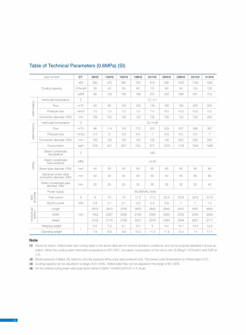
34
Table of Technical Parameters (0.6MPa) (SI)
Note1 Values for steam, chilled water and cooling water in the above table are for nominal operation conditions, and can be properly adjusted in actual op-
eration. When the cooling water inlet/outlet temperature is 30℃/36℃, the steam consumption of the unit is only 12.35kg/h · 104kcal/h with COP at
1.41.
2 Steam pressure 0.6Mpa G refers to unit inlet pressure without any valve pressure loss. The lowest outlet temperature for chilled water is 5℃.
3 Cooling capacity can be adjusted in a range of 20~100%. Chilled water fl ow can be adjusted in the range of 60~120%
4 On the chilled/cooling water side scale factor will be 0.086m2·K/kW 0.0001m
2·h ·℃/kcal .
Type number ST- 99H2 132H2 165H2 198H2 231H2 265H2 298H2 331H2 413H2
Cooling capacity
KW 350 470 580 700 810 930 1050 1160 1450
104kcal/h 30 40 50 60 70 80 90 100 125
USRt 99 132 165 198 231 265 298 331 413
Chille
d w
ate
r
Inlet/outlet temperature ℃ 12 → 7
Flow m3/h 60 80 100 120 140 160 180 200 250
Pressure loss mH2O 7.0 7.0 7.0 7.5 7.5 8.0 10.0 10.0 5.5
Connection diameter DN mm 100 100 125 125 150 150 150 150 200
Coolin
g w
ate
r
Inlet/outlet temperature ℃ 32 → 38
Flow m3/h 86 114 143 172 200 229 257 286 357
Pressure loss mH2O 4.2 5 5.8 6.6 7 8.8 5.5 5.5 7
Connection diameter DN mm 100 125 150 150 150 150 200 200 200
Ste
am
Consumption kg/h 376 501 627 752 877 1003 1128 1253 1566
Steam condensatetemperature ℃ ≤90
Steam condensateback pressure
MPa ≤0.05
Steam pipe diameter DN mm 40 50 50 65 65 65 65 80 80
Electrical control valveconnection diameter DN
mm 40 40 40 50 50 50 50 65 65
Steam condensate pipe diameter DN
mm 25 25 25 25 32 32 32 32 40
Ele
ctric
al
data
Power supply 3Φ380VAC-50Hz
Total current A 8 10 10 17.3 17.3 20.3 20.8 20.8 21.8
Electric power KW 3.8 4.1 4.1 5.9 5.9 6.8 7 7 7.2
Ove
rall
dim
ensio
ns
Length
mm
3810 3810 3790 3820 3840 3840 4357 4357 4855
Width 1942 2027 2060 2183 2308 2355 2332 2450 2558
Height 2152 2170 2169 2231 2316 2364 2384 2627 2717
Shipping weightt
6.5 7.3 8.1 8.3 9 9.4 10.1 10.5 12.8
Operating weight 7.8 8.9 9.9 10.3 11.4 11.9 13.4 14 17.1
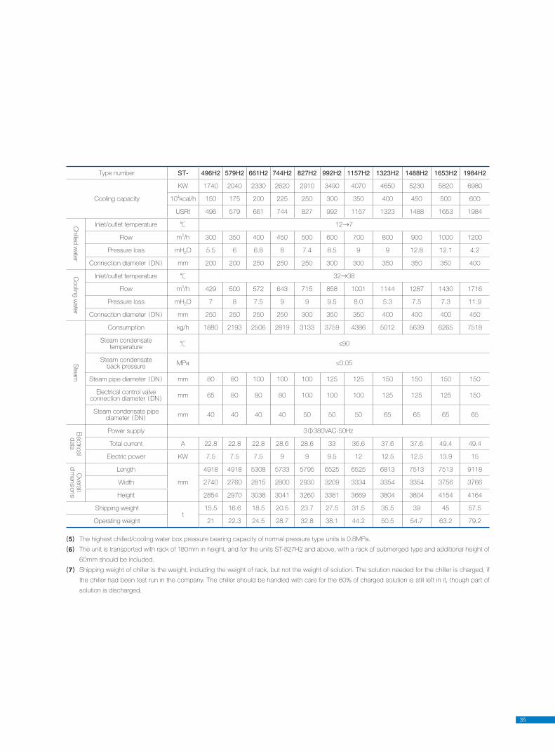
35
5 The highest chilled/cooling water box pressure bearing capacity of normal pressure type units is 0.8MPa.
6 The unit is transported with rack of 180mm in height, and for the units ST-827H2 and above, with a rack of sub merged type and additional height of
60mm should be included.
7 Shipping weight of chiller is the weight, including the weight of rack, but not the weight of solution. The solution needed for the chiller is charged, if
the chiller had been test run in the company. The chiller should be handled with care for the 60% of charged solution is still left in it, though part of
solution is discharged.
Type number ST- 496H2 579H2 661H2 744H2 827H2 992H2 1157H2 1323H2 1488H2 1653H2 1984H2
Cooling capacity
KW 1740 2040 2330 2620 2910 3490 4070 4650 5230 5820 6980
104kcal/h 150 175 200 225 250 300 350 400 450 500 600
USRt 496 579 661 744 827 992 1157 1323 1488 1653 1984
Chille
d w
ate
r
Inlet/outlet temperature ℃ 12→7
Flow m3/h 300 350 400 450 500 600 700 800 900 1000 1200
Pressure loss mH2O 5.5 6 6.8 8 7.4 8.5 9 9 12.8 12.1 4.2
Connection diameter DN mm 200 200 250 250 250 300 300 350 350 350 400
Coolin
g w
ate
r
Inlet/outlet temperature ℃ 32→38
Flow m3/h 429 500 572 643 715 858 1001 1144 1287 1430 1716
Pressure loss mH2O 7 8 7.5 9 9 9.5 8.0 5.3 7.5 7.3 11.9
Connection diameter DN mm 250 250 250 250 300 350 350 400 400 400 450
Ste
am
Consumption kg/h 1880 2193 2506 2819 3133 3759 4386 5012 5639 6265 7518
Steam condensatetemperature ℃ ≤90
Steam condensateback pressure
MPa ≤0.05
Steam pipe diameter DN mm 80 80 100 100 100 125 125 150 150 150 150
Electrical control valveconnection diameter DN
mm 65 80 80 80 100 100 100 125 125 125 150
Steam condensate pipe diameter DN
mm 40 40 40 40 50 50 50 65 65 65 65
Ele
ctric
al
data
Power supply 3Φ380VAC-50Hz
Total current A 22.8 22.8 22.8 28.6 28.6 33 36.6 37.6 37.6 49.4 49.4
Electric power KW 7.5 7.5 7.5 9 9 9.5 12 12.5 12.5 13.9 15
Ove
rall
dim
ensio
ns
Length
mm
4918 4918 5308 5733 5795 6525 6525 6813 7513 7513 9118
Width 2740 2760 2815 2800 2930 3209 3334 3354 3354 3756 3766
Height 2854 2970 3038 3041 3260 3381 3669 3804 3804 4154 4164
Shipping weightt
15.5 16.6 18.5 20.5 23.7 27.5 31.5 35.5 39 45 57.5
Operating weight 21 22.3 24.5 28.7 32.8 38.1 44.2 50.5 54.7 63.2 79.2
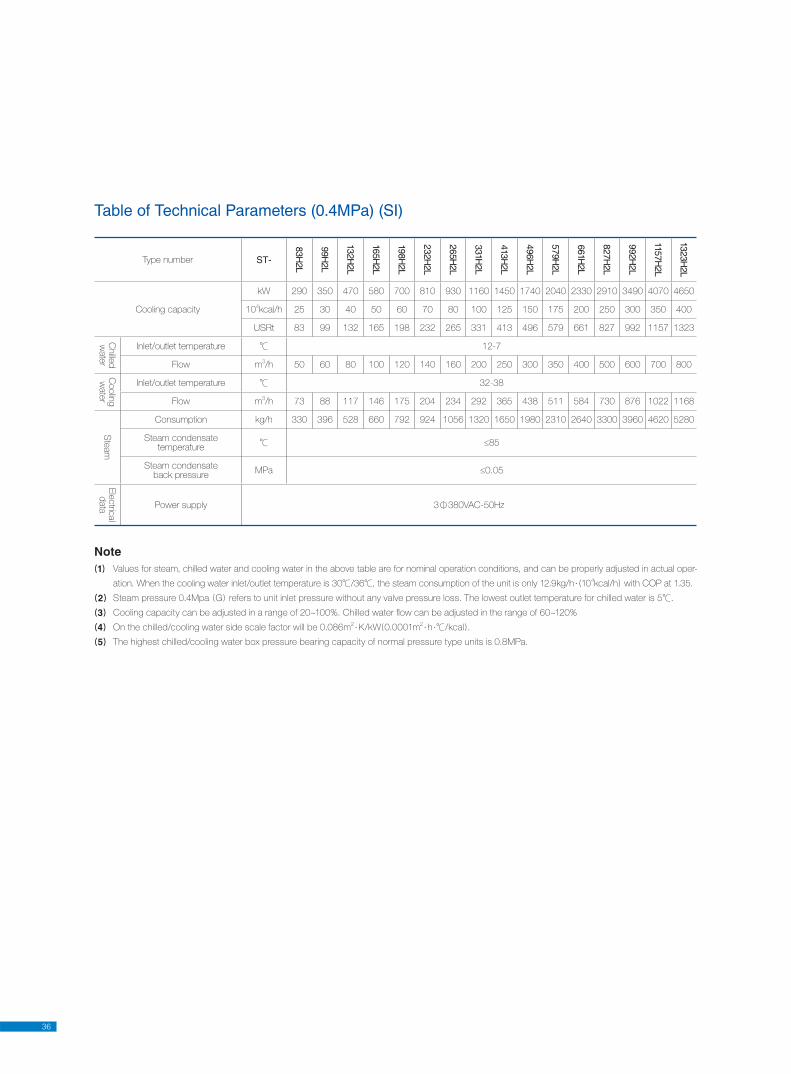
36
Table of Technical Parameters (0.4MPa) (SI)
Type number ST-
83H2L
99H2L
132H2L
165H2L
198H2L
232H2L
265H2L
331H2L
413H2L
496H2L
579H2L
661H2L
827H2L
992H2L
1157H2L
1323H2L
Cooling capacity
kW 290 350 470 580 700 810 930 1160 1450 1740 2040 2330 2910 3490 4070 4650
104kcal/h 25 30 40 50 60 70 80 100 125 150 175 200 250 300 350 400
USRt 83 99 132 165 198 232 265 331 413 496 579 661 827 992 1157 1323
Chille
d
wate
r
Inlet/outlet temperature ℃ 12-7
Flow m3/h 50 60 80 100 120 140 160 200 250 300 350 400 500 600 700 800
Coolin
g
wate
r
Inlet/outlet temperature ℃ 32-38
Flow m3/h 73 88 117 146 175 204 234 292 365 438 511 584 730 876 1022 1168
Ste
am
Consumption kg/h 330 396 528 660 792 924 1056 1320 1650 1980 2310 2640 3300 3960 4620 5280
Steam condensatetemperature ℃ ≤85
Steam condensateback pressure
MPa ≤0.05
Ele
ctric
al
data Power supply 3Φ380VAC-50Hz
Note1 Values for steam, chilled water and cooling water in the above table are for nominal operation conditions, and can be properly adjusted in actual oper-
ation. When the cooling water inlet/outlet temperature is 30℃/36℃, the steam consumption of the unit is only 12.9kg/h· 104kcal/h with COP at 1.35.
2 Steam pressure 0.4Mpa G refers to unit inlet pressure without any valve pressure loss. The lowest outlet temperature for chilled water is 5℃.
3 Cooling capacity can be adjusted in a range of 20~100%. Chilled water fl ow can be adjusted in the range of 60~120%
4 On the chilled/cooling water side scale factor will be 0.086m2·K/kW 0.0001m
2·h ·℃/kcal .
5 The highest chilled/cooling water box pressure bearing capacity of normal pressure type units is 0.8MPa.
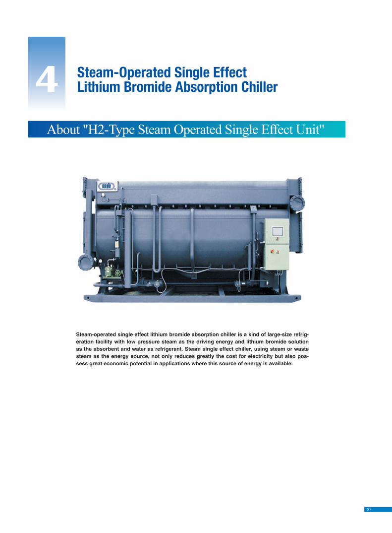
37
4 Steam-Operated Single EffectLithium Bromide Absorption Chiller
About "H2-Type Steam Operated Single Effect Unit"
Steam-operated single effect lithium bromide absorption chiller is a kind of large-size refrig-eration facility with low pressure steam as the driving energy and lithium bromide solution as the absorbent and water as refrigerant. Steam single effect chiller, using steam or waste steam as the energy source, not only reduces greatly the cost for electricity but also pos-sess great economic potential in applications where this source of energy is available.
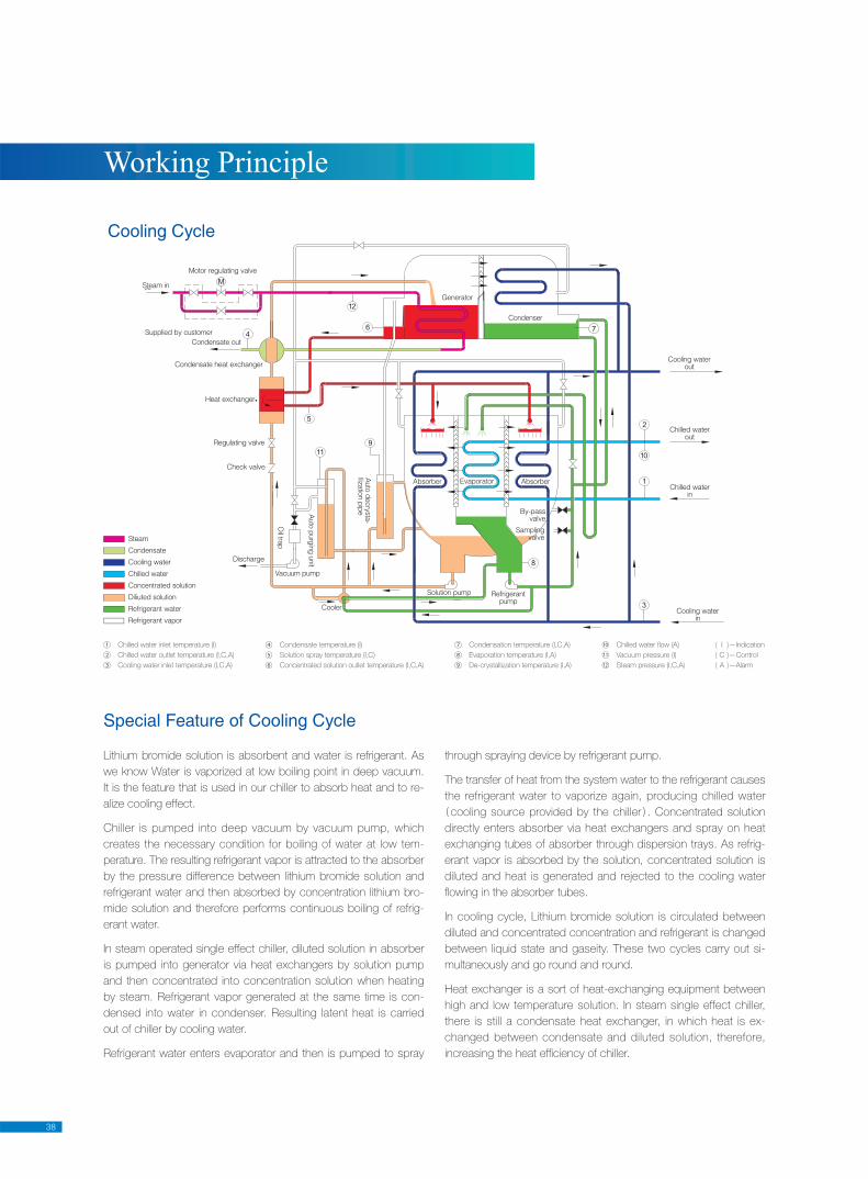
38
Working Principle
Steam
Condensate
Cooling water
Chilled water
Concentrated solution
Diliuted solution
Refrigerant water
Refrigerant vapor
Vacuum pump
Motor regulating valve
Steam in
Supplied by customer
Condensate out
Condensate heat exchanger
Heat exchanger
Regulating valve
Check valve
Discharge
Oil tra
p
Auto
purg
ing
unit
Auto
decry
sta
-lliz
atio
n p
ipe
Absorber
By-passvalve
Absorber
Condenser
Generator
Samplingvalve
Cooling waterout
Chilled waterout
Chilled waterin
Cooling waterin
Evaporator
Refrigerantpump
Solution pump
Cooler
Cooling Cycle
Lithium bromide solution is absorbent and water is refrigerant. As
we know Water is vaporized at low boiling point in deep vacuum.
It is the feature that is used in our chiller to absorb heat and to re-
alize cooling effect.
Chiller is pumped into deep vacuum by vacuum pump, which
creates the necessary condition for boiling of water at low tem-
perature. The resulting refrigerant vapor is attracted to the absorber
by the pressure difference between lithium bromide solution and
refrigerant water and then absorbed by concentration lithium bro-
mide solution and therefore performs continuous boiling of refrig-
erant water.
In steam operated single effect chiller, diluted solution in absorber
is pumped into generator via heat exchangers by solution pump
and then concentrated into concentration solution when heating
by steam. Refrigerant vapor generated at the same time is con-
densed into water in condenser. Resulting latent heat is carried
out of chiller by cooling water.
Refrigerant water enters evaporator and then is pumped to spray
through spraying device by refrigerant pump.
The transfer of heat from the system water to the refrigerant causes
the refrigerant water to vaporize again, producing chilled water
cooling source provided by the chiller . Concentrated solution
directly enters absorber via heat exchangers and spray on heat
exchanging tubes of absorber through dispersion trays. As refrig-
erant vapor is absorbed by the solution, concentrated solution is
diluted and heat is generated and rejected to the cooling water
fl owing in the absorber tubes.
In cooling cycle, Lithium bromide solution is circulated between
diluted and concentrated concentration and refrigerant is changed
between liquid state and gaseity. These two cycles carry out si-
multaneously and go round and round.
Heat exchanger is a sort of heat-exchanging equipment between
high and low temperature solution. In steam single effect chiller,
there is still a condensate heat exchanger, in which heat is ex-
changed between condensate and diluted solution, therefore,
increasing the heat effi ciency of chiller.
Special Feature of Cooling Cycle
① Chilled water inlet temperature (I)
② Chilled water outlet temperature (I,C,A)
③ Cooling water inlet temperature (I,C,A)
④ Condensate temperature (I)
⑤ Solution spray temperature (I,C)
⑥ Concentrated solution outlet temperature (I,C,A)
⑦ Condensation temperature (I,C,A)
⑧ Evaporation temperature (I,A)
⑨ De-crystallization temperature (I,A)
( I )—Indication
( C )—Control
( A )—Alarm
⑩ Chilled water fl ow (A)
⑪ Vacuum pressure (I)
⑫ Steam pressure (I,C,A)
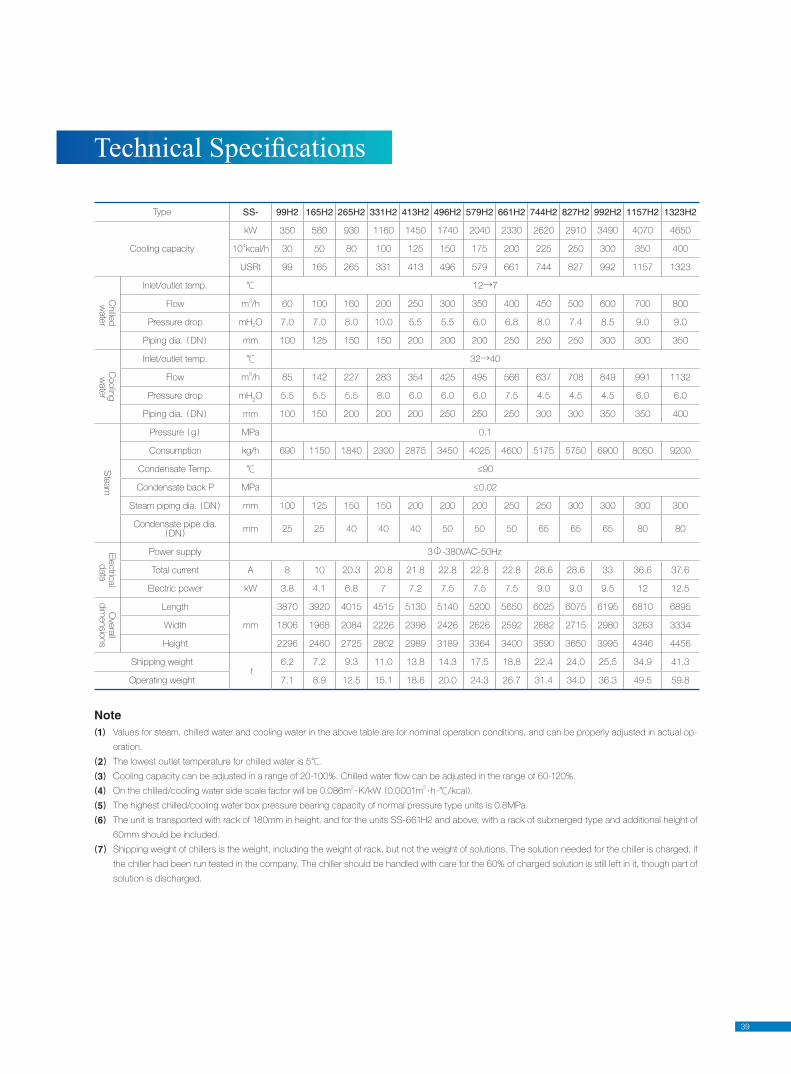
39
Note1 Values for steam, chilled water and cooling water in the above table are for nominal operation conditions, and can be properly adjusted in actual op-
eration.
2 The lowest outlet temperature for chilled water is 5℃.
3 Cooling capacity can be adjusted in a range of 20-100%. Chilled water fl ow can be adjusted in the range of 60-120%.
4 On the chilled/cooling water side scale factor will be 0.086m2·K/kW 0.0001m
2·h ·℃/kcal .
5 The highest chilled/cooling water box pressure bearing capacity of normal pressure type units is 0.8MPa.
6 The unit is transported with rack of 180mm in height, and for the units SS-661H2 and above, with a rack of submerged type and additional height of
60mm should be included.
7 Shipping weight of chillers is the weight, including the weight of rack, but not the weight of solutions. The solution needed for the chiller is charged, if
the chiller had been run tested in the company. The chiller should be handled with care for the 60% of charged solution is still left in it, though part of
solution is discharged.
Tech ni cal Spec i fi ca tions
Type SS- 99H2 165H2 265H2 331H2 413H2 496H2 579H2 661H2 744H2 827H2 992H2 1157H2 1323H2
Cooling capacity
kW 350 580 930 1160 1450 1740 2040 2330 2620 2910 3490 4070 4650
104kcal/h 30 50 80 100 125 150 175 200 225 250 300 350 400
USRt 99 165 265 331 413 496 579 661 744 827 992 1157 1323
Chille
d
wate
r
Inlet/outlet temp. ℃ 12→7
Flow m3/h 60 100 160 200 250 300 350 400 450 500 600 700 800
Pressure drop mH2O 7.0 7.0 8.0 10.0 5.5 5.5 6.0 6.8 8.0 7.4 8.5 9.0 9.0
Piping dia. DN mm 100 125 150 150 200 200 200 250 250 250 300 300 350
Coolin
g
wate
r
Inlet/outlet temp. ℃ 32→40
Flow m3/h 85 142 227 283 354 425 495 566 637 708 849 991 1132
Pressure drop mH2O 5.5 5.5 5.5 8.0 6.0 6.0 6.0 7.5 4.5 4.5 4.5 6.0 6.0
Piping dia. DN mm 100 150 200 200 200 250 250 250 300 300 350 350 400
Ste
am
Pressure g MPa 0.1
Consumption kg/h 690 1150 1840 2300 2875 3450 4025 4600 5175 5750 6900 8050 9200
Condensate Temp. ℃ ≤90
Condensate back P MPa ≤0.02
Steam piping dia. DN mm 100 125 150 150 200 200 200 250 250 300 300 300 300
Condensate pipe dia. DN
mm 25 25 40 40 40 50 50 50 65 65 65 80 80
Ele
ctric
al
data
Power supply 3Φ-380VAC-50Hz
Total current A 8 10 20.3 20.8 21.8 22.8 22.8 22.8 28.6 28.6 33 36.6 37.6
Electric power kW 3.8 4.1 6.8 7 7.2 7.5 7.5 7.5 9.0 9.0 9.5 12 12.5
Ove
rall
dim
ensio
ns
Length
mm
3870 3920 4015 4515 5130 5140 5200 5650 6025 6075 6195 6810 6895
Width 1806 1968 2084 2226 2398 2426 2626 2592 2682 2715 2980 3263 3334
Height 2296 2460 2725 2802 2989 3189 3364 3400 3590 3650 3995 4346 4456
Shipping weight t
6.2 7.2 9.3 11.0 13.8 14.3 17.5 18.8 22.4 24.0 25.5 34.9 41.3
Operating weight 7.1 8.9 12.5 15.1 18.6 20.0 24.3 26.7 31.4 34.0 36.3 49.5 59.8
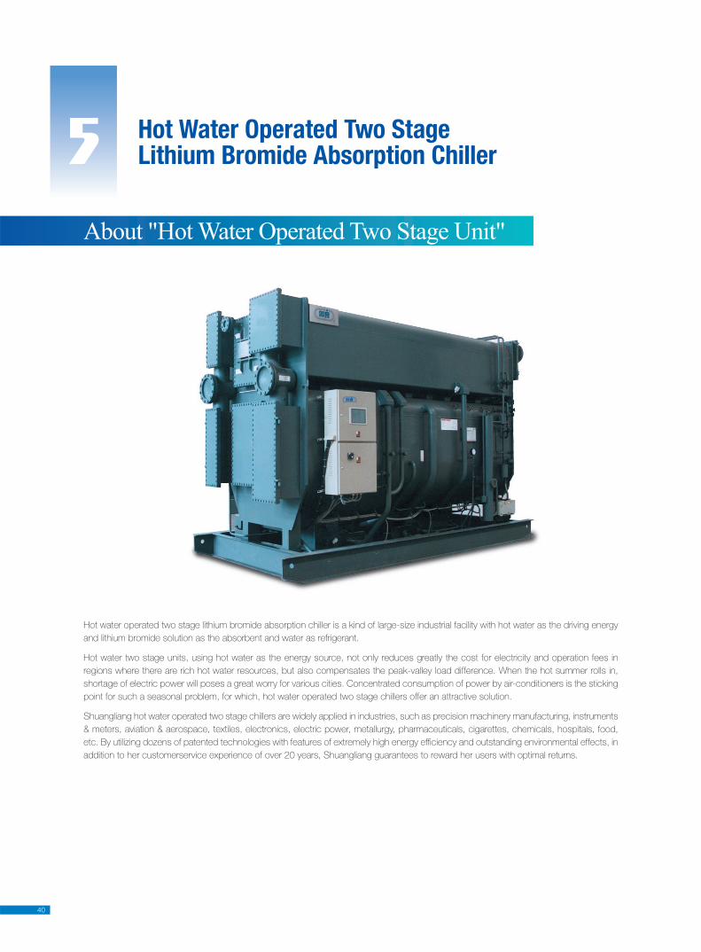
40
Hot water operated two stage lithium bromide absorption chiller is a kind of large-size industrial facility with hot water as the driving energy
and lithium bromide solution as the absorbent and water as refrigerant.
Hot water two stage units, using hot water as the energy source, not only reduces greatly the cost for electricity and operation fees in
regions where there are rich hot water resources, but also compensates the peak-valley load difference. When the hot summer rolls in,
shortage of electric power will poses a great worry for various cities. Concentrated consumption of power by air-conditioners is the sticking
point for such a seasonal problem, for which, hot water operated two stage chillers offer an attractive solution.
Shuangliang hot water operated two stage chillers are widely applied in industries, such as precision machinery manufacturing, instruments
& meters, aviation & aerospace, textiles, electronics, electric power, metallurgy, pharmaceuticals, cigarettes, chemicals, hospitals, food,
etc. By utilizing dozens of patented technologies with features of extremely high energy effi ciency and outstanding environmental effects, in
addition to her customerservice experience of over 20 years, Shuangliang guarantees to reward her users with optimal returns.
5 Hot Water Operated Two StageLithium Bromide Absorption Chiller
About "Hot Water Operated Two Stage Unit"
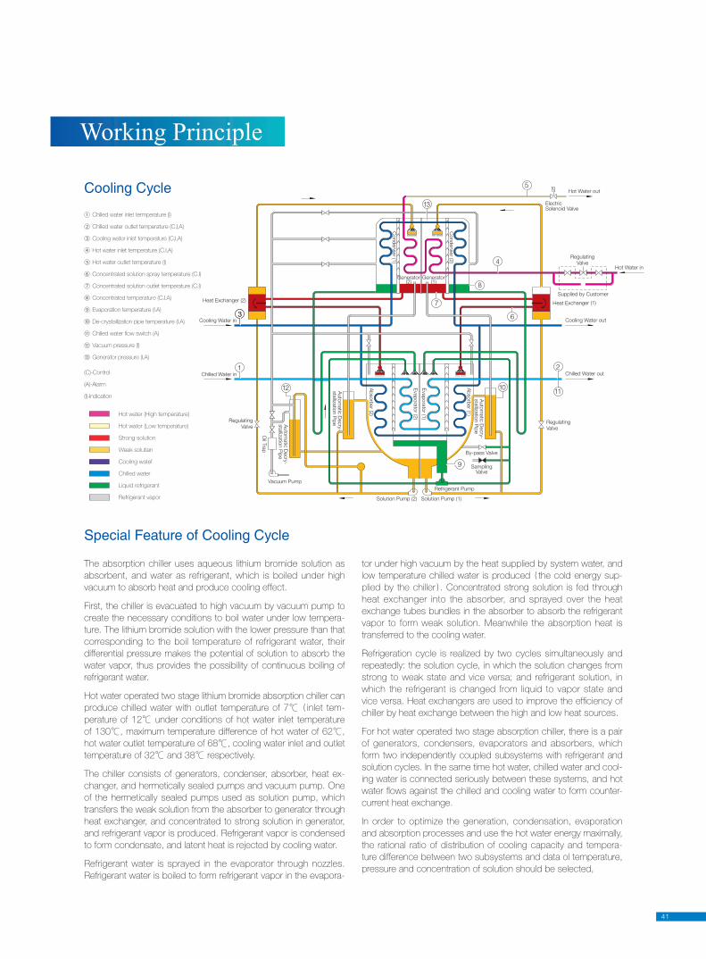
41
Working Principle
The absorption chiller uses aqueous lithium bromide solution as
absorbent, and water as refrigerant, which is boiled under high
vacuum to absorb heat and produce cooling effect.
First, the chiller is evacuated to high vacuum by vacuum pump to
create the necessary conditions to boil water under low tempera-
ture. The lithium bromide solution with the lower pressure than that
corresponding to the boil temperature of refrigerant water, their
differential pressure makes the potential of solution to absorb the
water vapor, thus provides the possibility of continuous boiling of
refrigerant water.
Hot water operated two stage lithium bromide absorption chiller can
produce chilled water with outlet temperature of 7℃ inlet tem-
perature of 12℃ under conditions of hot water inlet temperature
of 130℃, maximum temperature difference of hot water of 62℃,
hot water outlet temperature of 68℃, cooling water inlet and outlet
temperature of 32℃ and 38℃ respectively.
The chiller consists of generators, condenser, absorber, heat ex-
changer, and hermetically sealed pumps and vacuum pump. One
of the hermetically sealed pumps used as solution pump, which
transfers the weak solution from the absorber to generator through
heat exchanger, and concentrated to strong solution in generator,
and refrigerant vapor is produced. Refrigerant vapor is condensed
to form condensate, and latent heat is rejected by cooling water.
Refrigerant water is sprayed in the evaporator through nozzles.
Refrigerant water is boiled to form refrigerant vapor in the evapora-
tor under high vacuum by the heat supplied by system water, and
low temperature chilled water is produced the cold energy sup-
plied by the chiller . Concentrated strong solution is fed through
heat exchanger into the absorber, and sprayed over the heat
exchange tubes bundles in the absorber to absorb the refrigerant
vapor to form weak solution. Meanwhile the absorption heat is
transferred to the cooling water.
Refrigeration cycle is realized by two cycles simultaneously and
repeatedly: the solution cycle, in which the solution changes from
strong to weak state and vice versa; and refrigerant solution, in
which the refrigerant is changed from liquid to vapor state and
vice versa. Heat exchangers are used to improve the effi ciency of
chiller by heat exchange between the high and low heat sources.
For hot water operated two stage absorption chiller, there is a pair
of generators, condensers, evaporators and absorbers, which
form two independently coupled subsystems with refrigerant and
solution cycles. In the same time hot water, chilled water and cool-
ing water is connected seriously between these systems, and hot
water fl ows against the chilled and cooling water to form counter-
current heat exchange.
In order to optimize the generation, condensation, evaporation
and absorption processes and use the hot water energy maximally,
the rational ratio of distribution of cooling capacity and tempera-
ture difference between two subsystems and data ol temperature,
pressure and concentration of solution should be selected,
Special Feature of Cooling Cycle
1
33
12
5
4
8
6
7
9
10
2
11
13
Solution Pump (2) Solution Pump (1)
Refrigerant Pump
SamplingValve
By-pass Valve
Heat Exchanger (2)Heat Exchanger (1)
Cooling Water in
Chilled Water in
Regulating
Valve
Oil T
rap
Vacuum Pump
Auto
matic
Decry
-sta
llizatio
n P
ipe
Auto
matic
Decry
-sta
llizatio
n P
ipe
Auto
matic
Decry
-sta
llizatio
n P
ipe
Ab
sorb
er (2
)
Ab
sorb
er (1
)
Evap
ora
tor (2
)
Evap
ora
tor (1
)Generator
(2)Generator
(1)
Cond
enser (1
)
Cond
enser (2
)Regulating
Valve
Supplied by Customer
ElectricSolenoid Valve
Hot Water out
Hot Water in
Cooling Water out
Chilled Water out
Regulating
Valve
① Chilled water inlet termperature (I)
② Chilled water outlet temperature (C,I,A)
③ Cooling water inlet temperature (C,I,A)
④ Hot water inlet temperature (C.I,A)
⑤ Hot water outlet temperature (I)
⑥ Concentrated solution spray temperature (C.I)
⑦ Concentrated solution outlet temperature (C.I)
⑧ Concentrated temperature (C.I.A)
⑨ Evaporation temperature (I.A)
⑩ De-crystallization pipe temperature (I.A)
⑪ Chilled water fl ow switch (A)
⑫ Vacuum pressure (I)
⑬ Generator pressure (I,A)
(C)-Control
(A)-Alarm
(I)-Indication
Hot water (High temperature)
Hot water (Low temperature)
Strong solution
Weak solutian
Cooling watef
Chilled water
Liquid refrigerant
Refrigerant vapor
Cooling Cycle
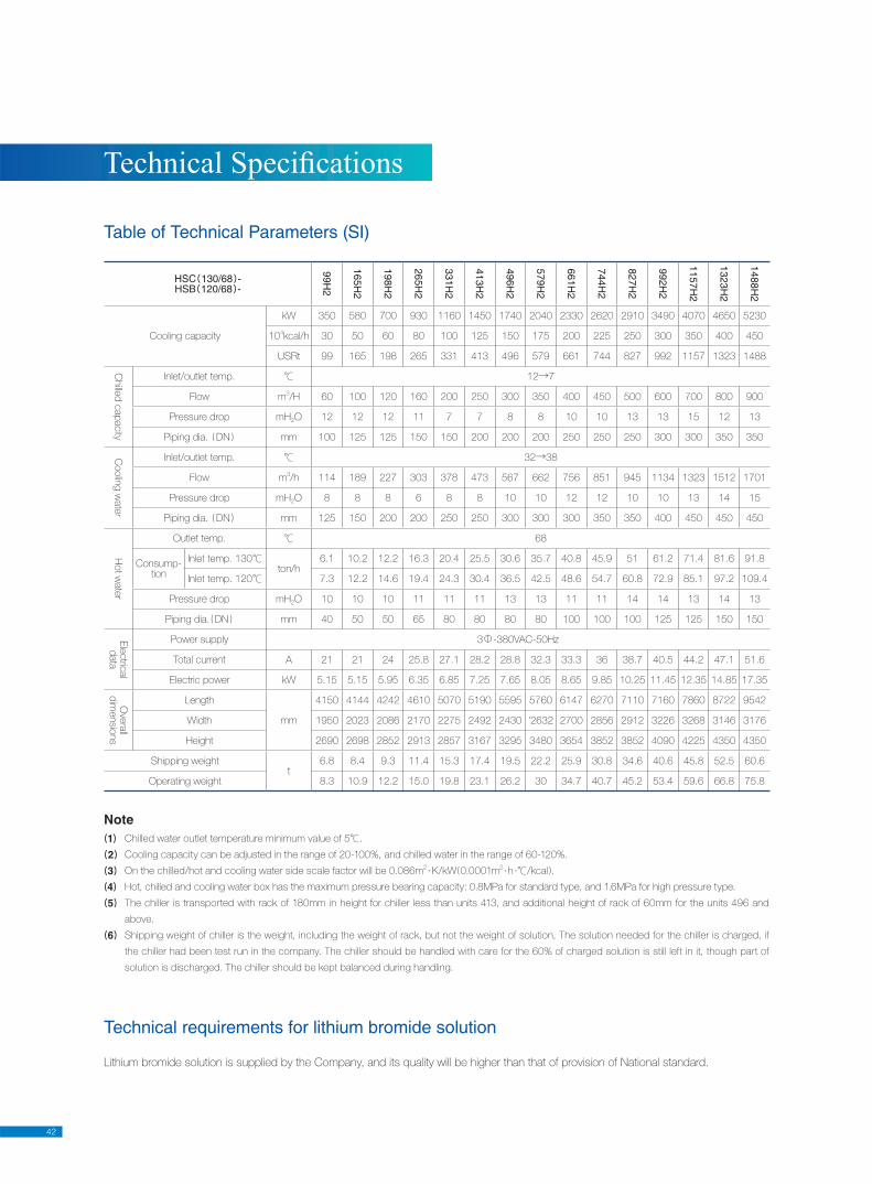
42
Tech ni cal Spec i fi ca tions
Note1 Chilled water outlet temperature minimum value of 5℃.
2 Cooling capacity can be adjusted in the range of 20-100%, and chilled water in the range of 60-120%.
3 On the chilled/hot and cooling water side scale factor will be 0.086m2·K/kW 0.0001m
2·h ·℃/kcal .
4 Hot, chilled and cooling water box has the maximum pressure bearing capacity: 0.8MPa for standard type, and 1.6MPa for high pressure type.
5 The chiller is transported with rack of 180mm in height for chiller less than units 413, and additional height of rack of 60mm for the units 496 and
above.
6 Shipping weight of chiller is the weight, including the weight of rack, but not the weight of solution, The solution needed for the chiller is charged, if
the chiller had been test run in the company. The chiller should be handled with care for the 60% of charged solution is still left in it, though part of
solution is discharged. The chiller should be kept balanced during handling.
Table of Technical Parameters (SI)
Technical requirements for lithium bromide solution
Lithium bromide solution is supplied by the Company, and its quality will be higher than that of provision of National standard.
HSC 130/68 -HSB 120/68 -
99H2
165H2
198H2
265H2
331H2
413H2
496H2
579H2
661H2
744H2
827H2
992H2
1157H2
1323H2
1488H2
Cooling capacity
kW 350 580 700 930 1160 1450 1740 2040 2330 2620 2910 3490 4070 4650 5230
104kcal/h 30 50 60 80 100 125 150 175 200 225 250 300 350 400 450
USRt 99 165 198 265 331 413 496 579 661 744 827 992 1157 1323 1488
Chille
d c
ap
acity
Inlet/outlet temp. ℃ 12→7
Flow m3/H 60 100 120 160 200 250 300 350 400 450 500 600 700 800 900
Pressure drop mH2O 12 12 12 11 7 7 8 8 10 10 13 13 15 12 13
Piping dia. DN mm 100 125 125 150 150 200 200 200 250 250 250 300 300 350 350
Coolin
g w
ate
r
Inlet/outlet temp. ℃ 32→38
Flow m3/h 114 189 227 303 378 473 567 662 756 851 945 1134 1323 1512 1701
Pressure drop mH2O 8 8 8 6 8 8 10 10 12 12 10 10 13 14 15
Piping dia. DN mm 125 150 200 200 250 250 300 300 300 350 350 400 450 450 450
Hot w
ate
r
Outlet temp. ℃ 68
Consump-tion
Inlet temp. 130℃ ton/h
6.1 10.2 12.2 16.3 20.4 25.5 30.6 35.7 40.8 45.9 51 61.2 71.4 81.6 91.8
Inlet temp. 120℃ 7.3 12.2 14.6 19.4 24.3 30.4 36.5 42.5 48.6 54.7 60.8 72.9 85.1 97.2 109.4
Pressure drop mH2O 10 10 10 11 11 11 13 13 11 11 14 14 13 14 13
Piping dia. DN mm 40 50 50 65 80 80 80 80 100 100 100 125 125 150 150
Ele
ctric
al
data
Power supply 3Φ-380VAC-50Hz
Total current A 21 21 24 25.8 27.1 28.2 28.8 32.3 33.3 36 38.7 40.5 44.2 47.1 51.6
Electric power kW 5.15 5.15 5.95 6.35 6.85 7.25 7.65 8.05 8.65 9.85 10.25 11.45 12.35 14.85 17.35
Ove
rall
dim
ensio
ns
Length
mm
4150 4144 4242 4610 5070 5190 5595 5760 6147 6270 7110 7160 7860 8722 9542
Width 1950 2023 2086 2170 2275 2492 2430 '2632 2700 2856 2912 3226 3268 3146 3176
Height 2690 2698 2852 2913 2857 3167 3295 3480 3654 3852 3852 4090 4225 4350 4350
Shipping weight t
6.8 8.4 9.3 11.4 15.3 17.4 19.5 22.2 25.9 30.8 34.6 40.6 45.8 52.5 60.6
Operating weight 8.3 10.9 12.2 15.0 19.8 23.1 26.2 30 34.7 40.7 45.2 53.4 59.6 66.8 75.8
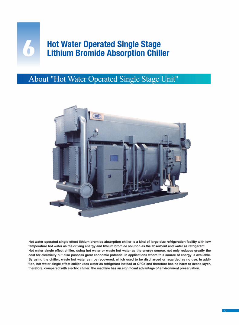
43
6 Hot Water Operated Single StageLithium Bromide Absorption Chiller
About "Hot Water Operated Single Stage Unit"
Hot water operated single effect lithium bromide absorption chiller is a kind of large-size refrigeration facility with low temperature hot water as the driving energy and lithium bromide solution as the absorbent and water as refrigerant.Hot water single effect chiller, using hot water or waste hot water as the energy source, not only reduces greatly the cost for electricity but also possess great economic potential in applications where this source of energy is available. By using the chiller, waste hot water can be recovered, which used to be discharged or regarded as no use. In addi-tion, hot water single effect chiller uses water as refrigerant instead of CFCs and therefore has no harm to ozone layer, therefore, compared with electric chiller, the machine has an significant advantage of environment preservation.
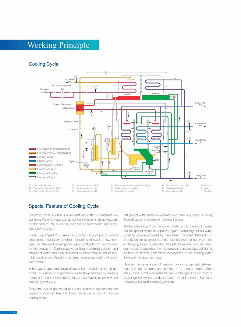
44
Working Principle
SolutionPump
Cooler
RefrigerantPump
SamplingValve
By-passValve
Heat Exchanger
Supplied By Customer
Motor Regulating Valve
Hot WaterOut
Hot WaterIn
Regulation Valve
Check Valve
Discharge
Oil T
rap
VacuumPump
Absorber AbsorberEvaporator
GeneratorCondenser
Cooling WaterOut
Cooling WaterIn
Chilled WaterOut
Chilled WaterIn
Auto
Purg
ing U
nit
Auto
matic
Decry
sta
llizatio
nP
ipe
Hot water (High temperature)
Hot water (Low temperature)
Cooling water
Chilled water
Concentrated solution
Diluted solution
Refrigerant water
Refrigerant vapor
Lithium bromide solution is absorbent and water is refrigerant. As
we know Water is vaporized at low boiling point in deep vacuum.
It is the feature that is used in our chiller to absorb heat and to re-
alize cooling effect.
Chiller is pumped into deep vacuum by vacuum pump, which
creates the necessary condition for boiling of water at low tem-
perature. The resulting refrigerant vapor is attracted to the absorber
by the pressure difference between lithium bromide solution and
refrigerant water and then absorbed by concentration lithium bro-
mide solution and therefore performs continuous boiling of refrig-
erant water.
In hot water operated single effect chiller, diluted solution in ab-
sorber is pumped into generator via heat exchangers by solution
pump and then concentrated into concentration solution when
heating by hot water.
Refrigerant vapor generated at the same time is condensed into
water in condenser. Resulting latent heat is carried out of chiller by
cooling water.
Refrigerant water enters evaporator and then is pumped to spray
through spraying device by refrigerant pump.
The transfer of heat from the system water to the refrigerant causes
the refrigerant water to vaporize again, producing chilled water
cooling source provided by the chiller . Concentrated solution
directly enters absorber via heat exchangers and spray on heat
exchanging tubes of absorber through dispersion trays. As refrig-
erant vapor is absorbed by the solution, concentrated solution is
diluted and heat is generated and rejected to the cooling water
fl owing in the absorber tubes.
Heat exchanger is a sort of heat-exchanging equipment between
high and low temperature solution. In hot water single effect
chiller, there is still a condensate heat exchanger, in which heat is
exchanged between condensate and diluted solution, therefore,
increasing the heat effi ciency of chiller.
Special Feature of Cooling Cycle
Cooling Cycle
① Chilled water inlet temp. (I)
② Chilled water outlet temp. (I,C,A)
③ Cooling water inlet temp. (I,C,A)
④ Hot water inlet temp. (I,C,A)
⑤ Hot water outlet temp. (I)
⑥ Solution spray temp. (I,C)
⑦ Concentrated solution outlet temp. (I,C,A)
⑧ Condensation temp. (I,C,A)
⑨ Evaporation temp. (I,A)
(C)—Control
(A)—Alarm
(I)—Indication
⑩ De-crystallization temp. (I,A)
⑪ Chilled water fl ow (A)
⑫ Vacuum pressure (I)
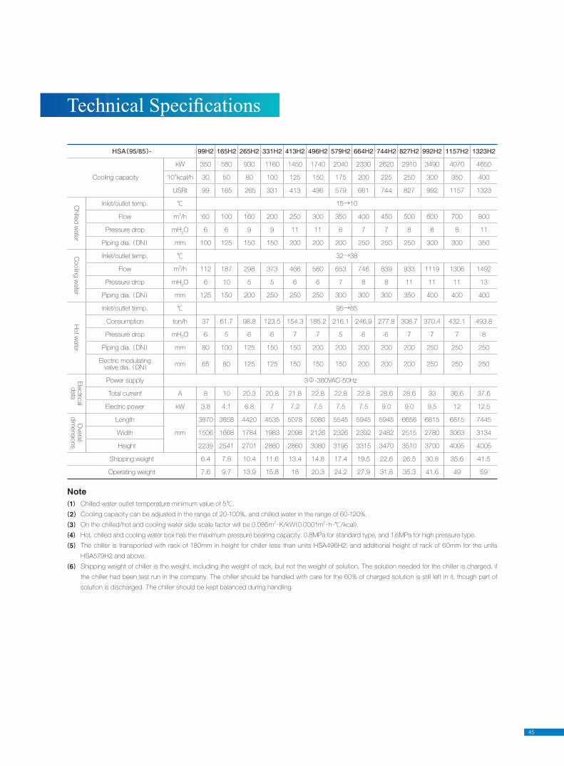
45
Tech ni cal Spec i fi ca tions
Note1 Chilled water outlet temperature minimum value of 5℃.
2 Cooling capacity can be adjusted in the range of 20-100%, and chilled water in the range of 60-120%.
3 On the chilled/hot and cooling water side scale factor will be 0.086m2·K/kW 0.0001m
2·h ·℃/kcal .
4 Hot, chilled and cooling water box has the maximum pressure bearing capacity: 0.8MPa for standard type, and 1.6MPa for high pressure type.
5 The chiller is transported with rack of 180mm in height for chiller less than units HSA496H2, and additional height of rack of 60mm for the units
HSA579H2 and above.
6 Shipping weight of chiller is the weight, including the weight of rack, but not the weight of solution, The solution needed for the chiller is charged, if
the chiller had been test run in the company. The chiller should be handled with care for the 60% of charged solution is still left in it, though part of
solution is discharged. The chiller should be kept balanced during handling.
HSA 95/85 - 99H2 165H2 265H2 331H2 413H2 496H2 579H2 664H2 744H2 827H2 992H2 1157H2 1323H2
Cooling capacity
kW 350 580 930 1160 1450 1740 2040 2330 2620 2910 3490 4070 4650
104kcal/h 30 50 80 100 125 150 175 200 225 250 300 350 400
USRt 99 165 265 331 413 496 579 661 744 827 992 1157 1323
Chille
d w
ate
r
Inlet/outlet temp. ℃ 15→10
Flow m3/h 60 100 160 200 250 300 350 400 450 500 600 700 800
Pressure drop mH2O 6 6 9 9 11 11 6 7 7 8 8 8 11
Piping dia. DN mm 100 125 150 150 200 200 200 250 250 250 300 300 350
Coolin
g w
ate
r
Inlet/outlet temp. ℃ 32→38
Flow m3/h 112 187 298 373 466 560 653 746 839 933 1119 1306 1492
Pressure drop mH2O 6 10 5 5 6 6 7 8 8 11 11 11 13
Piping dia. DN mm 125 150 200 250 250 250 300 300 300 350 400 400 400
Hot w
ate
r
Inlet/outlet temp. ℃ 95→85
Consumption ton/h 37 61.7 98.8 123.5 154.3 185.2 216.1 246.9 277.8 308.7 370.4 432.1 493.8
Pressure drop mH2O 6 5 6 6 7 7 5 6 6 7 7 7 8
Piping dia. DN mm 80 100 125 150 150 200 200 200 200 200 250 250 250
Electric modulating valve dia. DN
mm 65 80 125 125 150 150 150 200 200 200 250 250 250
Ele
ctric
al
data
Power supply 3Φ-380VAC-50Hz
Total current A 8 10 20.3 20.8 21.8 22.8 22.8 22.8 28.6 28.6 33 36.6 37.6
Electric power kW 3.8 4.1 6.8 7 7.2 7.5 7.5 7.5 9.0 9.0 9.5 12 12.5
Ove
rall
dim
ensio
ns
Length
mm
3870 3858 4420 4535 5078 5080 5545 5945 5945 6656 6815 6815 7445
Width 1506 1668 1784 1983 2098 2126 2326 2392 2482 2515 2780 3063 3134
Height 2239 2541 2701 2860 2860 3080 3195 3315 3470 3510 3700 4005 4005
Shipping weight 6.4 7.8 10.4 11.6 13.4 14.8 17.4 19.5 22.6 26.5 30.8 35.6 41.5
Operating weight 7.6 9.7 13.9 15.8 18 20.3 24.2 27.9 31.8 35.3 41.6 49 59
Specifi cations Subject to change without prior notice
JIANGSU SHUANGLIANG AIR-CONDITIONINGEQUIPMENT CO., LTD.
Add: Shuangliang Industrial Park, Ligang, Jiangyin, Jiangsu, P.R.China Tel: +86-510-86638824 / 86632095 Fax: +86-510-86634678 / 86631154Post Code: 214444http://www.shuangliang.come-mail: [email protected]
NO. SL-IT-C200906(E)
Distributed by