absolute track geometry, what is it and how does it help...
TRANSCRIPT

www.fugro.com/raildata1
Absolute Track Geometry, what is it and how does it help me?Fugro, Jack Vogelaar Global Business Development Manager Rail
Fugro RailData: alignment computations based upon RILA Track survey

www.fugro.com/raildata2
ATG is a very accurate description of the track center line.
Absolute because we can tell you within (H) 3/8” (10 mm) and (V) 19/32” (15 mm) where your track is in space.
We process the data and use a CORS network for positioning.
Track geometry, a description of a 3D polyline in predefined horizontal or vertical elements of track center line checked upon compliance to local standards.
Continuously Operating Reference Stations USA
Surveyed tracks HAR-PHL-NYC
Absolute Track Geometry (ATG)
www.fugro.com/raildata3
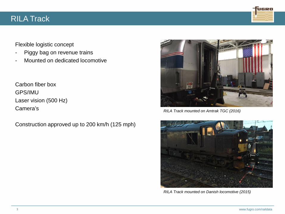
Flexible logistic concept- Piggy bag on revenue trains- Mounted on dedicated locomotive
Carbon fiber boxGPS/IMULaser vision (500 Hz)Camera’s
Construction approved up to 200 km/h (125 mph)
RILA Track mounted on Amtrak TGC (2016)
RILA Track mounted on Danish locomotive (2015)
RILA Track

www.fugro.com/raildata4
RILA Track, data of rail and track center line

www.fugro.com/raildata5
RILA captures during the survey high resolution video images , which can be used for object identification and asset management.Add sticky notes to objects in the video when you see something you would normally write down in the field.This allows you to extract a list of notes e.g. for a reconstruction behind your desk instead of going into the track.
RILA – georeferenced video mapping

www.fugro.com/raildata6
Flexible logistic concept- Mounted on dedicated locomotive
GPS/IMULaser scanning (200 HZ, 1 million pps)Camera’s
Construction approved up to 160 km/h (100 mph) RILA Track and RILA 360 mounted on Class 66
RILA Track and RILA 360 on G&W Rail Feeding loco
RILA 360
RILA Track and RILA 360 on WC Railway loco

www.fugro.com/raildata7
Typical point cloud of RILA 360, here part of the shunt yard just before entering Eindhoven Central Station.
RILA 360 point cloud

www.fugro.com/raildata8
RILA Track and RILA 360 for detailed information of railway corridor.Detailed engineering scheme.
RILA Track and RILA 360 mounted and ready to go for a survey in the UK.
USA RILA 3.0 with integrated scanner for scanning surroundings
Developments RILA Track + RILA 360 = RILA 3.0
Fugro RailData: alignment computations based upon RILA Track survey

www.fugro.com/raildata9
Map your network during normal service without any surveyors in the tracks. Improve efficiency & safety in 1 run.
RILA Technology: from survey to tamping
Bringing the Railway to your computer
RILA Technology:• No staff on or near the track => increased safety performance;• No possessions required => increased railway capacity;• Rich data set: Survey once => use many times;• High accuracy => highest levels of approvals;• Affordable => cost reductions to 90%.

www.fugro.com/raildata10
essential information for rail professionals
Bringing the Railway to your computer
RILA ATG RILA RTG RILA S&C
RILA
RILA (360) RILA (360) RILA (360)
RILA (360) Absolute tamping

www.fugro.com/raildata11
Check on the input file from the RILA Track survey:
• Completeness• Units (metric, foot/inches)• Format• Sigma's (σxy, σz), typically 3/8” H, 19/32” V• Super elevation (cant or cross level)• Curvature• Direction: ascending chainage (mileage)
Graph showing σxy and σz
Graph showing super elevation
ATG data (inch)

www.fugro.com/raildata12
An alignment is a 3D geometric definition of the track consisting of tangents (straights), curves, spirals (transition curve) and super elevation (cant).
The horizontal alignment (plane view) describes the geometry of the track center line, the vertical alignment (vertical plane) describes the geometry of the lower rail.
An alignment based upon survey data and without any further improvements is a “best fit” or “as built”.
Based upon these H+V alignments quality and safety checks can be done using local standards or regulations.
The alignments can be used to optimize track wear, maintenance operations or as input for a re-design.
Shot of RILA video somewhere between PHL - HAR
Track definitions
Alignment (inches)
Top of Rail
Super elevationTrack center
Track center line
Horizontal alignment
Track symmetrical center line

www.fugro.com/raildata13
KRDZ-file of track center line(s)
Constraints• S&C• Platforms• Level crossings• Slab track• OLE• Bridges/Viaducts
Standards/regulations• International Standards • Regional Standards (Europe: TSI INF 1299/2014,
US: PGRE Section 6 Railway Track Design)• Local Standards (OVS)
Complex track situation Rotterdam CS (Netherlands)
European standard for alignment
Input

www.fugro.com/raildata14
First step is to determine where curvature, tangent track (straights) and spirals (transition curves) are situated.
For this we use the graph of curvature and super elevation.
The straights and curves are determined using the least square method.
In between straights and curves spirals are computed.
This gives a first draft alignment not taking any constraints into account.
The above steps are integrated into software like Bentley Rail-track or Leica A-track
In the meanwhile check for location of platforms, crossings, slab track.
Determine straight using least square method
Slab track in a tunnel in Berlin
Horizontal First Draft

www.fugro.com/raildata15
In this stage check for:
Maximum slews (especially near platforms, S&C, level crossings, Structures and objects)
In case of crossings, adjacent tracks parallel
Distance between adjacent tracks (UK: SCX)
Does location of spiral equals location of transition of super elevation (runoff)
Track gauge should be sufficient for trains to pass
Adjacent track should be parallel
Horizontal final
Min. ValuesMax. ValuesStandard Values Except. Values
Horizontal Curves Rh [m]

www.fugro.com/raildata16
Now we’re adding maximal permitted speed and measured averaged super elevation.
This to check some safety parameters.
Super elevation (Cant) is defined by:
Due to mixed traffic, not all trains run at the same speed.Therefore an average speed (equilibrium) is used to determine the super elevation.
Super elevation deficiency shortfall of super elevationExcess of super elevation
Check on length and location of spiral and transition of super elevation and gradient of runoff
Worn inner curve rail due tot deficiency of super elevation
Curve with superelevation of tracks on the Keystone Corridor near Rosemont, PA
Horizontal add and check speed and super elevation (foot)
Eth = Dc * 0,0007 * Vmax2

www.fugro.com/raildata17
Minimum length of element
Minimum Radius/Curvature
Comfort parameters like • sudden changes in lateral acceleration• tilting speed• warp
Minimum length depends on speed
Very comfortable wooden benches
Horizontal check on regulations (OVS/CFR)
Standard. Values Except. ValuesMin. Values
Spiral [m] acceptable centrifugal forces
Max. Values
Runoff [m] range of change of super elevation
Warp (dD/ds)
Determine spiral length and runoff

www.fugro.com/raildata18
Like the horizontal alignment the first step is to determine where curvature (sags and valleys) and gradients are situated.For this we use the graph of curvature and super elevation.
Again the gradients and curves are determined using the least square method.
This gives a first draft alignment not taking any constraints into account.
The above steps are integrated into software like Bentley Rail-track or Leica A-track
Bridges interact the vertical layout
Track through mountains -> vertical layout is a challenge
Vertical first draft
www.fugro.com/raildata19
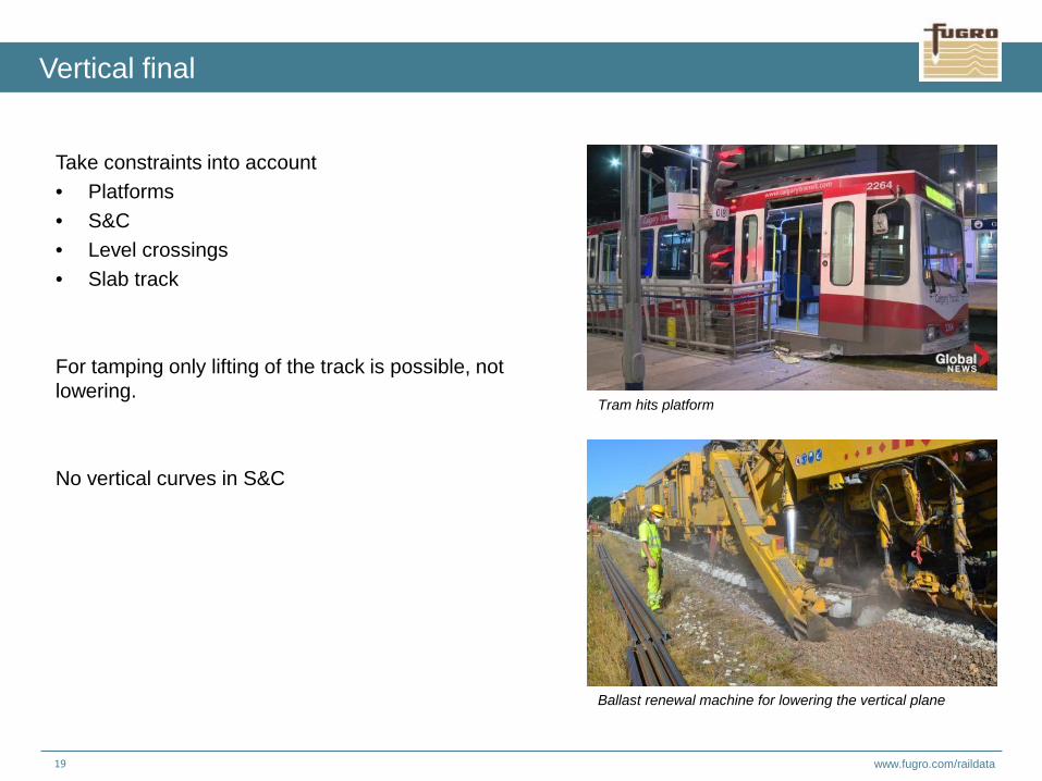
Take constraints into account• Platforms• S&C• Level crossings• Slab track
For tamping only lifting of the track is possible, not lowering.
No vertical curves in S&C
Tram hits platform
Ballast renewal machine for lowering the vertical plane
Vertical final

www.fugro.com/raildata20
Abrupt changes in vertical accelerations:
When formula is not met a gradient should be applied between summit and valley
Check for maximum track gradient but also gradients near platforms and shunting yards
Vertical accelerations are thrilling in a roller coasters
Very steep slope during construction of Railroad in Africa
Vertical check on regulations (OVS/CFR)
Sag Valley
Max. ValuesStandard. Values Except. Values
Thresholds for gradients

www.fugro.com/raildata21
Although both horizontal and vertical plane are within all thresholds the combination of the two could cause consequential accelerations which exceed comfort parameters.
The combination of a horizontal curve and a gradient will increase resistance which in some cases could lead to more horse power
Combination Horizontal and Vertical alignment
Standard. Values
Combination of horizontal and vertical curves
Except. Values

www.fugro.com/raildata22
Alignment of track center line; Horizontal plane: radius -4825 meter ; vertical plane: gradient 0.46 %
RILA Portal

www.fugro.com/raildata23
Slew and lift for each individual point
RILA Portal

www.fugro.com/raildata24
For a safe train journey the distance to adjacent track and objects should be large enough to let trains pass.
Depending on speed.
• SC0, distance to objects• SCP, distance to platform and awnings• SCX, distance to adjacent track(s)
SC0: Typical object gauging picture Network Rail
SCP: Platform gauging UK
Additional information: Clearance profile

www.fugro.com/raildata25
Input for a new OLE design.
Safety and Asset management:Height and stagger
Just finished building an OLE design in the Netherlands
Stagger out of thresholds will lead to severe damage to contact wire and droppers
Additional Information: Overhead Line Equipment

www.fugro.com/raildata26 Essential Infrastructure Information for Rail Professionals
Automated tamping input into WIN-ALC Plasser & Theurer
• Green is preferred alignment;• Red: RILA-measurement (current
alignment)• Measuring data coupled to XYZ• Comparison measurement runs via XYZ
ΔZ (lift)
Direct into WIN-ALC

www.fugro.com/raildata27
Summary
Essential Infrastructure Information for Rail Professionals
RILA SURVEY Technology:• No staff on or near the track => increased safety performance;• No possessions required => increased railway capacity;• Rich data set: Survey once => use many times;• High accuracy => highest levels of approvals;• Affordable => cost reductions to 90%.
RILA absolute position tamping:• No surveyors on or near the track for setting out;• Track alignments maintained as (origionally) approved designs;• Extended life of track and track components;• Toal cost of ownership significantly reduced.

www.fugro.com/raildata28 Fugro RailData: alignment computations based upon RILA Track survey
Thank you for your attention
Website:www.fugro.com/raildata
Jack VogelaarM: +31 655 855 524E: [email protected]
USA: Morgan ReedM: +1 337 962 0885E: [email protected]