abs3500-ce english ver.1.6 - braxton bragg · “ce” dec la ra t ion of con fo r mit y the com...
TRANSCRIPT

.
ABS3500-CE
AU TO MATIC BRIDGE SAW
OWNER’S MAN UAL
ENG LISH

MAN U FAC TURER
For any as sis tance or re quest for spare parts, please con tact your lo cal dealer or the man u fac -turer di rectly by tele phon ing or writ ing to:
ACHILLI S.R.L.
Via Montescudo 148
P.O. Box Ag.10 Gros
47900 RIMINI (It aly)
Tel +39 0541 387066 r.a.
Fax +39 0541 389058

INTRODUCTION
This in struc tion man ual is ad dressed to the user of the ma chine and con tains all the in for ma tionre gard ing in stal la tion, use and main te nance and pro vides all the nec es sary in for ma tionconcerning safety.
The in struc tion man ual must be kept near the ma chine, away from dirt and hu mid ity and al ways at hand for ref er ence.
This ma chine is in tended ex clu sively for the spe cific use for which it is de signed. Any other use iscon sid ered im proper and there fore dan ger ous. The man u fac turer can not be held re spon si ble forpos si ble dam age de riv ing from im proper use due to non-com pli ance with the safety and op er at -ing reg u la tions in di cated in this instruction manual.
Through out this in struc tion man ual an ex cla ma tion mark in an equi lat eral tri an gle is used to pointout an im por tant warn ing to which par tic u lar at ten tion must be paid.
This sym bol, lo cated on the blade guard, sig nals the ob li ga tion to use hear ing and eye pro tec tion.
This sym bol, lo cated on the elec tric box, sig nals dan ger ous volt age which may be of suf fi cient in -ten sity to con sti tute a risk of elec tric shock.
This sym bol, lo cated on the blade guard, sig nals the ob li ga tion to read the in struc tion man ual be -fore in stal la tion of the machine.

INDEX
“CE” DECLARATION OF CONFORMITY . . . . . . . . . . . . . . . . . . . . . . . . . . . . . . . . . . . . . . . . . . . Page 1
CHAPTER # 1 MACHINE INFORMATION AND SAFETY . . . . . . . . . . . . . . . . . . . . . . . . . . Page 21.0 INTENDED USE OF THE MACHINE . . . . . . . . . . . . . . . . . . . . . . . . . . . . . . . . . . . . Page 21.1 CONTRAINDICATIONS . . . . . . . . . . . . . . . . . . . . . . . . . . . . . . . . . . . . . . . . . . . . . . Page 21.2 MAIN MACHINE PARTS. . . . . . . . . . . . . . . . . . . . . . . . . . . . . . . . . . . . . . . . . . . . . . Page 41.3 SAFETY HINTS . . . . . . . . . . . . . . . . . . . . . . . . . . . . . . . . . . . . . . . . . . . . . . . . . . . . Page 41.4 IDENTIFICATION PLATE . . . . . . . . . . . . . . . . . . . . . . . . . . . . . . . . . . . . . . . . . . . . . Page 61.5 TECHNICAL DATA . . . . . . . . . . . . . . . . . . . . . . . . . . . . . . . . . . . . . . . . . . . . . . . . . . Page 61.6 NOISE LEVEL. . . . . . . . . . . . . . . . . . . . . . . . . . . . . . . . . . . . . . . . . . . . . . . . . . . . . . Page 9
CHAPTER # 2 INSTALLATION . . . . . . . . . . . . . . . . . . . . . . . . . . . . . . . . . . . . . . . . . . . . . . Page 102.0 UNLOADING THE MACHINE. . . . . . . . . . . . . . . . . . . . . . . . . . . . . . . . . . . . . . . . . Page 102.1 LOCATION AND LEVELLING. . . . . . . . . . . . . . . . . . . . . . . . . . . . . . . . . . . . . . . . . Page 112.2 INSTALLING THE SLIDING GUIDE EXTENSIONS. . . . . . . . . . . . . . . . . . . . . . . . Page 122.3 ELECTRICAL CONNECTION AND GROUNDING . . . . . . . . . . . . . . . . . . . . . . . . Page 122.3 ACCESSORIES . . . . . . . . . . . . . . . . . . . . . . . . . . . . . . . . . . . . . . . . . . . . . . . . . . . Page 14
CHAPTER # 3 MACHINE FUNCTIONING . . . . . . . . . . . . . . . . . . . . . . . . . . . . . . . . . . . . . Page 153.0 GENERAL CONCEPTS OF PROGRAM FUNCTIONING . . . . . . . . . . . . . . . . . . . Page 153.1 GENERAL CONCEPTS OF ELECTRICAL FUNCTIONING . . . . . . . . . . . . . . . . . Page 153.2 MACHINE SAFETY SYSTEMS . . . . . . . . . . . . . . . . . . . . . . . . . . . . . . . . . . . . . . . Page 153.3 MOTOR PROTECTIONS . . . . . . . . . . . . . . . . . . . . . . . . . . . . . . . . . . . . . . . . . . . . Page 163.4 ROLLER TABLE . . . . . . . . . . . . . . . . . . . . . . . . . . . . . . . . . . . . . . . . . . . . . . . . . . . Page 17
CHAPTER # 4 MACHINING . . . . . . . . . . . . . . . . . . . . . . . . . . . . . . . . . . . . . . . . . . . . . . . . Page 184.0 BLADE MOUNTING AND REPLACEMENT. . . . . . . . . . . . . . . . . . . . . . . . . . . . . . Page 184.1 BLADE SELECTION AND USE . . . . . . . . . . . . . . . . . . . . . . . . . . . . . . . . . . . . . . . Page 194.2 START-UP. . . . . . . . . . . . . . . . . . . . . . . . . . . . . . . . . . . . . . . . . . . . . . . . . . . . . . . . Page 20
CHAPTER # 5 MAINTENANCE AND CLEANING. . . . . . . . . . . . . . . . . . . . . . . . . . . . . . . . Page 235.0 MAINTENANCE AND CLEANING . . . . . . . . . . . . . . . . . . . . . . . . . . . . . . . . . . . . . Page 23
CHAPTER # 6 ADJUSTMENT AND REPLACEMENT . . . . . . . . . . . . . . . . . . . . . . . . . . . . Page 256.0 ADJUSTMENT OF HEAD BEARINGS. . . . . . . . . . . . . . . . . . . . . . . . . . . . . . . . . . Page 256.1 TRAVERSE-GUIDE WHEEL ADJUSTMENT. . . . . . . . . . . . . . . . . . . . . . . . . . . . . Page 266.2 ADJUSTING THE BRAKING SYSTEM . . . . . . . . . . . . . . . . . . . . . . . . . . . . . . . . . Page 266.3 “W” AXIS REDUCTION UNIT CLUTCH ADJUSTMENT . . . . . . . . . . . . . . . . . . . . Page 276.4 SENSOR ADJUSTMENT . . . . . . . . . . . . . . . . . . . . . . . . . . . . . . . . . . . . . . . . . . . . Page 286.5 MAIN MOTOR ALIGNMENT . . . . . . . . . . . . . . . . . . . . . . . . . . . . . . . . . . . . . . . . . Page 296.6 REPLACEMENT OF ROLLER TABLE ROLLER (OPTIONAL) . . . . . . . . . . . . . . . Page 296.7 DISMANTLING THE ROLLER TABLE HYDRAULIC JACK (OPTIONAL) . . . . . . . Page 30
CHAPTER # 7 DIAGNOSIS . . . . . . . . . . . . . . . . . . . . . . . . . . . . . . . . . . . . . . . . . . . . . . . . . Page 317.0 TROUBLE-SHOOTING . . . . . . . . . . . . . . . . . . . . . . . . . . . . . . . . . . . . . . . . . . . . . Page 317.1 PROGRAM MESSAGE DIAGNOSTICS. . . . . . . . . . . . . . . . . . . . . . . . . . . . . . . . . Page 357.2 “CNC” AXIS CONTROL MESSAGE DIAGNOSTICS . . . . . . . . . . . . . . . . . . . . . . Page 387.3 INVERTER DIAGNOSTIC . . . . . . . . . . . . . . . . . . . . . . . . . . . . . . . . . . . . . . . . . . . Page 397.4 ASSISTANCE . . . . . . . . . . . . . . . . . . . . . . . . . . . . . . . . . . . . . . . . . . . . . . . . . . . . . Page 43
CHAPTER # 8 WIRING DIAGRAMS . . . . . . . . . . . . . . . . . . . . . . . . . . . . . . . . . . . . . . . . . . Page 458.0 ELECTRICAL PANEL LAYOUT . . . . . . . . . . . . . . . . . . . . . . . . . . . . . . . . . . . . . . . Page 45

8.1 WIRING DIAGRAMS 400 Volt 50/60 Hz. . . . . . . . . . . . . . . . . . . . . . . . . . . . . . . . . Page 488.2 OPTIONAL ACCESSORY . . . . . . . . . . . . . . . . . . . . . . . . . . . . . . . . . . . . . . . . . . . Page 538.3 HYDRAULIC DIAGRAM . . . . . . . . . . . . . . . . . . . . . . . . . . . . . . . . . . . . . . . . . . . . . Page 54
LIMITED WARRANTY CERTIFICATE . . . . . . . . . . . . . . . . . . . . . . . . . . . . . . . . . . . . . . . . . . . . Page 73
Rev. 08.2005 1.6

“CE” DEC LA RA TION OF CON FOR MITY
The com pany:
ACHILLI S.R.L.
Via Montescudo 148
I 47900 RIMINI
in the per son of its le gal rep re sen ta tive and as man u fac turer of the:
AU TO MATIC BRIDGE SAW FOR MAR BLE AND GRAN ITE
MODEL
SERIAL NO.
YEAR OF MANUFACTURE
de clares on its sole re spon si bil ity that the ma chine is con structed in com pli ance with all the es -sen tial safety and health re quire ments pro vided for by the Directives:
89/392/CEE - 91/368/CEE - 93/44/CEE - 93/68/CEE
89/336/CEE- 92/31/CEE
73/23/CEE
and in con for mity with the fol low ing reg u la tions and reg u la tory doc u ments:
EN 292/1 - EN 292/2 - EN 60204/1 - EN 349
DLG 04/12/92 N° 476 (for Italy)
DPR 24/07/96 N° 459 (for Italy)
ACHILLI S.R.L.
Le gal Rep re sen ta tive

CHAPTER # 1 MACHINE INFORMATION AND SAFETY
1.0 INTENDED USE OF THE MACHINE
The bridge saw ABS/CE is ex tremely ro bust, easy to use and with suit -able cut ting pre ci sion.
The head “9” (Fig.2) of the ma chine is mo tor-driven on three axis (lon -gi tu di nal “X”, transversal “Y”, ver ti cal “Z”). The lon gi tu di nal andtransversal move ments oc cur at a speed ad just able be tween 0 and 7m/min., while for the ver ti cal axis from 0 to 0.3 m/min.
The main mo tor “2” (Fig.2) can be turned man u ally and fixed in 4right-an gle po si tions (0° - 90° - 180° - 270°) to al low ex e cut ing per pen -dic u lar cuts with out mov ing the slab (see Fig.1/a). The disc po si tion isin di cated on the “W” axis; ro ta tion oc curs at a speed of about 6 rpm.
Fur ther more, in clined cuts from 90° to 45° may be ex e cuted, by man u -ally in clin ing the head (see Fig.1/b). A 45°-cut can be made with thedisc in 90°-po si tion on the “W” axis.
The bridge saw is de signed for cut ting mar ble, gran ite and nat u ralstone slabs with a max i mum thick ness of 140 mm. Nev er the less,slabs with a thick ness of greater than 20 mm. must be cut in stages.
The cut ting tool must be a di a mond blade with an ex ter nal di am e ter of500 mm. and spe cif i cally for the ma te rial to be cut.
This ma chine is con structed in con for mity with the fol low ing reg u la tions:
EN 292/1 - EN 292/2 - EN 349 - EN 60204/1
and, there fore, meet the es sen tial re quire ments for safety and health pro tec tion.
1.1 CONTROINDICATIONS
– The Achilli bridge saw may not be used to cut wood, plas tics, met als or sim i lar ma te ri als.
– The ma chine can not be used in any other way than that for which it was de signed.
– Do not carry out ma chin ing of ma te ri als of which the weight and di men sions are not pro por tion -ate to the struc ture of the machine.
– Any mod i fi ca tion which al ters the char ac ter is tics of the ma chine must be made by the man u -fac turer only, who will at test to the con for mity. There fore, any mod i fi ca tion or main te nance op -er a tion not in cluded in this man ual is to be considered unauthorized.
2 OWNER'S MANUAL - BRIDGE SAW MOD. ABS/CE
Fig.1a
Fig.1b

OWNER'S MANUAL - BRIDGE SAW MOD. ABS/CE 3
Fig.2

1.2 MAIN MACHINE PARTS
The ma chine con sists of the fol low ing main parts (Fig.2):
1) Elec tric panel
2) Main mo tor
3) Lon gi tu di nal feed mo tor “X”
4) Cross feed mo tor “Y”
5) Lift ing/low er ing mo tor “Z”
6) Work ta ble
7) Lon gi tu di nal head slid ing beam “X”
8) Tra verse head slid ing guide “Y”
9) Head
10) Blade guard
11) Iden ti fi ca tion plate
12) Wa ter col lec tor tank (op tional)
13) So le noid valve for wa ter
14) Wa ter re cy cling pump (op tional)
15) Roller ta ble
16) Hy drau lic con trol unit
17) Mo bile con trol panel
18) Wa ter flow sen sor
19) “W” axis elec tric mo tor
1.3 SAFETY HINTS
– Care fully read this man ual be fore in stal la tion of the ma chine and keep it for fu ture ref er ence.
– Clear the work ing area from any ob jects which could be a source of dan ger.
– En sure that the sur face on which the ma chine will be in stalled is strong enough too carry theweight and that the nec es sary sta bil ity is guar an teed.
– Keep the work ing area clean and en sure ad e quate light ing.
– Wear suit able cloth ing: al ways wear ear phones, glasses, pro tec tion gloves, ro bust shoes andhair cover. Re move rings, watches and any other jew elry; but ton cuffs tightly around the wrist.
– In stall the power sup ply ca ble in such a way that ac ci den tal con tact with hot, cut ting or cor ro -sive ob jects, or per sons is avoided; it is also rec om mended to un wind it completely.
– Do not use the ma chine when the power sup ply ca ble is dam aged or not in per fect con di tion.
– En sure that the ground ing con nected to the elec tric line is ef fi cient.
4 OWNER'S MANUAL - BRIDGE SAW MOD. ABS/CE

– En sure that the di a mond blade used is per fectly bal anced, cen tered, straight and well tight -ened.
– Avoid cut ting too big or too small pieces or pieces too dif fi cult to po si tion for cut ting.
– Keep hands ab so lutely clear of the tool cut ting line.
– Be fore car ry ing out any main te nance, re pair or re place ment work, switch off the ma chine byturn ing the switch “QS1” (Fig.8) to the po si tion “0” and lock it by means of a pad lock; fur ther -more, en sure that no body is near the ma chine to pre vent any pos si ble accidents.
– Check that no mov ing part of the ma chine is blocked or dam aged. Check that all the parts aremounted cor rectly in or der to guar an tee proper func tion ing of the ma chine.
– Be fore start ing the ma chine, en sure that the blade guard is well tight ened.
– Do not leave the ma chine un at tended and do not al low it to be used by un au tho rized or un -trained per son nel.
– Dur ing cut ting op er a tions, the ma chine may pro duce a high level of noise; there fore, the use ofear phones is oblig a tory to pro tect hearing.
– In case of ma chine break downs or bad func tion ing, switch off the ma chine and call in as sis -tance from the dealer or the man u fac turer.
– Do not ex pose the ma chine to at mo spheric agents (rain, sun, hu mid ity, etc.).
– When it is de cided to no lon ger use the ma chine be cause it is ob so lete or ir rep a ra bly dam aged, shut it down com pletely to pre vent accidents.
Dis con nect the ma chine from the mains and dis man tle the tool.
Pro ceed with dis posal in con for mity with the reg u la tions in force, con sult ing lo cal or ga ni za tions set up for such operations.
The machine is constructed with the following materials:
Steel Ac
Aluminium Al
Polyamide Pa
Copper Cu
Wood
Hydraulic oil (optional)
OWNER'S MANUAL - BRIDGE SAW MOD. ABS/CE 5

1.4 IDENTIFICATION PLATE
The iden ti fi ca tion plate of the ma chine is lo cated on theright shoul der “11” (Fig.2) and car ries the fol low ing in -for ma tion (Fig.3):
A) Ma chine model
B) Se rial num ber
C) Power
D) Volt age and fre quency
E) Cur rent ab sorp tion
F) De gree of IP pro tec tion
G) Max. di am e ter of tool
H) Weight
I) Year of man u fac ture
L) CE mark ing
NOTE: Each time the man u fac turer is con sulted, the se rial num ber and ma chine model spec i fiedon the iden ti fi ca tion plate must be indicated.
1.5 TECHNICAL DATA
AU TO MATIC BRIDGE SAW modelABS3500CE
ELEC TRI CAL DATA
Main mo tor. . . . . . . . . . . . . . . . . . . . . . . . . . . . . . . . . . . . . . . . . . . . . . . . . . . Three-pha se
Po wer . . . . . . . . . . . . . . . . . . . . . . . . . . . . . . . . . . . . . . . . . . . . . . . . . . . . . . . . . . . 11 KW
Vol ta ge . . . . . . . . . . . . . . . . . . . . . . . . . . . . . . . . . . . . . . . . . . . . . . . . . . . . . . . . . . 400 V~
Fre quency . . . . . . . . . . . . . . . . . . . . . . . . . . . . . . . . . . . . . . . . . . . . . . . . . . . . . . . . 50 Hz
Ro ta tion spe ed ad ju sta ble by me ans of in ver ter . . . . . . . . . . . . . . . . . . . . 800-3000 rpm
Lon gi tu di nal or cross head feed mo tor. . . . . . . . . . . . . . . . . . . . . . . . . . . . . Three-pha se
Po wer . . . . . . . . . . . . . . . . . . . . . . . . . . . . . . . . . . . . . . . . . . . . . . . . . . . . . . . . . 0.75 KW
Vol ta ge . . . . . . . . . . . . . . . . . . . . . . . . . . . . . . . . . . . . . . . . . . . . . . . . . . . . . . . . . . 400 V~
Fre quency . . . . . . . . . . . . . . . . . . . . . . . . . . . . . . . . . . . . . . . . . . . . . . . . . . . . . . . . 50 Hz
Adju sta ble spe ed by me ans of in ver ter in both run ning di rec tions . . . from 0 to 7 m/min.
Lif ting/lo we ring mo tor . . . . . . . . . . . . . . . . . . . . . . . . . . . . . . . . . . . . . . . . . . Three-pha se
Po wer . . . . . . . . . . . . . . . . . . . . . . . . . . . . . . . . . . . . . . . . . . . . . . . . . . . . . . . . . . 0.37 KW
Vol ta ge . . . . . . . . . . . . . . . . . . . . . . . . . . . . . . . . . . . . . . . . . . . . . . . . . . . . . . . . . . 400 V~
Fre quency . . . . . . . . . . . . . . . . . . . . . . . . . . . . . . . . . . . . . . . . . . . . . . . . . . . . . . . . 50 Hz
Adju sta ble spe ed by me ans of in ver ter in both run ning di rec tions . . from 0 to 0.3 m/min.
W-axis ro ta tion mo tor . . . . . . . . . . . . . . . . . . . . . . . . . . . . . . . . . . . . . . . . . . Three-pha se
Po wer . . . . . . . . . . . . . . . . . . . . . . . . . . . . . . . . . . . . . . . . . . . . . . . . . . . . . . . . . 0.18 KW
Vol ta ge . . . . . . . . . . . . . . . . . . . . . . . . . . . . . . . . . . . . . . . . . . . . . . . . . . . . . . . . . . 230 V~
6 OWNER'S MANUAL - BRIDGE SAW MOD. ABS/CE
Fig.3

Fre quency . . . . . . . . . . . . . . . . . . . . . . . . . . . . . . . . . . . . . . . . . . . . . . . . . . . . . . . . 50 Hz
Ro ta tion spe ed . . . . . . . . . . . . . . . . . . . . . . . . . . . . . . . . . . . . . . . . . . . . . . . . . 1400 RPM
Wa ter recycling pump (op tio nal) . . . . . . . . . . . . . . . . . . . . . . . . . . . . . . . . . Sin gle-pha se
Po wer . . . . . . . . . . . . . . . . . . . . . . . . . . . . . . . . . . . . . . . . . . . . . . . . . . . . . . . . . . 0.5 KW
Vol ta ge . . . . . . . . . . . . . . . . . . . . . . . . . . . . . . . . . . . . . . . . . . . . . . . . . . . . . . . . . . 400 V~
Fre quency . . . . . . . . . . . . . . . . . . . . . . . . . . . . . . . . . . . . . . . . . . . . . . . . . . . . . . . . 50 Hz
Max. head . . . . . . . . . . . . . . . . . . . . . . . . . . . . . . . . . . . . . . . . . . . . . . . . . . . . . . . . 2/10 m
Ca pa city. . . . . . . . . . . . . . . . . . . . . . . . . . . . . . . . . . . . . . . . . . . . . . . . . . . . . 160/30 l/min.
Hydra u lic con trol unit mo tor. . . . . . . . . . . . . . . . . . . . . . . . . . . . . . . . . . . . . . Three-pha se
Po wer . . . . . . . . . . . . . . . . . . . . . . . . . . . . . . . . . . . . . . . . . . . . . . . . . . . . . . . . . 0.18 KW
Vol ta ge . . . . . . . . . . . . . . . . . . . . . . . . . . . . . . . . . . . . . . . . . . . . . . . . . . . . . . . . . . 400 V~
Fre quency . . . . . . . . . . . . . . . . . . . . . . . . . . . . . . . . . . . . . . . . . . . . . . . . . . . . . . . . 50 Hz
Ro ta tion spe ed . . . . . . . . . . . . . . . . . . . . . . . . . . . . . . . . . . . . . . . . . . . . . . . . . 2800 RPM
ME CHAN I CAL DATA
– Diamond blade . . . . . . . . . . . . . . . . . . . . . . . . . . . . . . . . . . . . . . . . . . . . . . . . . E500 mm.
– Blade peripheral speed (min./max.) . . . . . . . . . . . . . . . . . . . . . . . . . . . 20.9/ 78.5 m./sec.
– Max. longitudinal motion . . . . . . . . . . . . . . . . . . . . . . . . . . . . . . . . . . . . . . . . . . 3700 mm.
– Max. cross motion . . . . . . . . . . . . . . . . . . . . . . . . . . . . . . . . . . . . . . . . . . . . . . . 2080 mm.
– Max. vertical motion . . . . . . . . . . . . . . . . . . . . . . . . . . . . . . . . . . . . . . . . . . . . . . . 205 mm.
– Cutting height with E500 mm blade. . . . . . . . . . . . . . . . . . . . . . . . . . . . . . . . . . 100 mm.
– Hydraulic pump oil type. . . . . . . . . . . . . . . . . . . . . . . . . . . . . . . . . . . . . . . . . . . . . . ISO 15
– Oil lubricating for W-axis rotation system . . . . . . . . . . . . . . . . “ROLOIL” ARM100PE type
– Head inclination . . . . . . . . . . . . . . . . . . . . . . . . . . . . . . . . . . . . . . . . . . . . . from 90° to 45°
– Main motor rotation . . . . . . . . . . . . . . . . . . . . . . . . . . . . . . . . . . . . . . . . . . from 0° to 270°
– Net weight machine. . . . . . . . . . . . . . . . . . . . . . . . . . . . . . . . . . . . . . . . . . . . . . . . 2730 kg
– Water collector tank capacity (optional) . . . . . . . . . . . . . . . . . . . . . . . . . . . . approx. 470 l
– Shipping dimensions with packaging (WxLxH) . . . . . . . . . . . . . . . 2250x5380x2340 mm.
– Shipping dimension with packaging and transport wheel . . . . . . . 2250x5380x2540 mm.
– Machine frame galvanized and some parts with epoxy powder finish.
OWNER'S MANUAL - BRIDGE SAW MOD. ABS/CE 7

OVER ALL DI MEN SIONS AND AD JUST MENT
NOTE: Mea sure ments taken in mm.
8 OWNER'S MANUAL - BRIDGE SAW MOD. ABS/CE

1.6 NOISE LEVEL
Noise level mea sure ment in con for mity with EN 24871 (CEN 23744) reg u la tions:
Acoustic pressure level at operator positionempty 75.3 dB (A)
Acoustic pressure level at operator positionloaded 83.4 dB (A)
The val ues in di cated above were mea sured us ing a di a mond blade of 500 mm. on a slab of mar -ble 20 mm. thick. Fac tors which af fect the noise level are:
– Time of ex po sure.
– Char ac ter is tics of fac tory.
– Ad ja cent ma chines, etc.
The noise level may be con tained by:
– Cor rect choice of tool.
– Ef fi cient cut ting ca pac ity of the tool.
– Low-speed cut ting.
It is rec om mended to use si lenced di a mond blades, in or der to con sid er ably limit theacous tic pres sure level emit ted by the ma chine dur ing operation.
The em ployer is obliged to make the fol low ing pro vi sions:
– Limit the ex po sure time by in tro duc ing shift work.
– Sup ply in di vid ual means of pro tec tion and in struct the op er a tor on its use.
– Sub mit the ma chine op er a tor to pe ri odic health check ups.
OWNER'S MANUAL - BRIDGE SAW MOD. ABS/CE 9

CHAPTER # 2 INSTALLATION
2.0 UNLOADING THE MACHINE
A fork lift truck must be used for un load ing of the ma chine (Fig.4).
WARN ING: Take the fol low ing pre cau tions for lift ing the ma chine:
– Use a lift truck of ad e quate ca pac ity for the weight and di men sions of the ma chine.
– The forks “A” (Fig.4) of the lift truck must be at least as long as the width of the ma chine.
– The grip ping points for lift ing are marked with two wooden pan els po si tioned un der the ma -chine frame.
– Take all the nec es sary steps to en sure max i mum sta bil ity of un load ing equip ment and loads.
– An nounce and sig nal the ma noeuvre in ad vance.
– Avoid pass ing the sus pended load over per sons or places where drop ping of the load could bedan ger ous.
Take ex treme care to safe guard the in teg rity of all the ma chine parts, par tic u larly the lon gi tu di nalhead slid ing beam “7” (Fig.2) and the race way for the cableholder chain lo cated at the top of thema chine.
The ma chine is as sem bled and care fully tested at our fac tory in or der to guar an tee ef fi cient op er -a tion and is packed in such a way as to en sure pro tec tion dur ing freight. The con di tion of the pack -ing must be checked be fore open ing to be sure that the ma chine has not been dam aged or tam -pered with dur ing trans port. If any signs of this are found, a com plaint must be filled with the freight com pany, if pos si ble ac com pa nied by pho to graphs.
10 OWNER'S MANUAL - BRIDGE SAW MOD. ABS/CE
Fig.4

2.1 LOCATION AND LEVELLING
Place the ma chine in an area with a well-lev elled floorin non-de form able ma te rial and far away from wallsand pil lars.
Check that there is suf fi cient space around the ma -chine to al low free move ment of the piece to be ma -chined.
It is very im por tant that the ma chine be placed levelus ing a very long and ac cu rate spirit level, plac ing thelat ter along the tra verse slide guides “8” (Fig.2) of thema chine (see Fig.6). Or use a short pre ci sion levelpo si tion ing it in the zone in di cated by an ar row en -graved in the tra verse sliding guide.
If nec es sary, act on the spe cial ad just ing screws lo cated on the ma chine leg.
– Fix the ma chine to the floor with fourthreaded bars or four ex pan sion plugs ofad e quate di men sions. For drill ing re fer toFig.5.
– In stall the slid ing guide ex ten sions fol low -ing the in struc tions in Chap ter 2.2.
– Prop erly po si tion the me chan i cal stop ofthe mo bile panel arm:
• Re move the me chan i cal stop.
• Turn the stop up side down and lock itwith the spe cial screw “B” Fig.6/a.
OWNER'S MANUAL - BRIDGE SAW MOD. ABS/CE 11
Fig.6
Fig.5
Fig.6a

2.2 INSTALLING THE SLIDING GUIDE EXTENSIONS
Re move the lock ing brack ets “T”(Fig.6/b), one for each shoul der. Fixthe two ex ten sion guards “R” to thetwo shoul ders with the three spe cialscrews.
In stall the ex ten sion “Q”, one for eachshoul der. Join the ex ten sion to the fix -ing plate by means of the 4 screws “P”. The fix ing plate “S” must be po si tionedbe hind the slid ing guide.
The top end of the guide must be per -fectly aligned with the top end of theex ten sion. In sert the two elas tic pins“U”, tighten the 4 screws “P”.
Move the limit switch “SQ3” (“Y-” axis) on the shoul der “DX” and fix it in the out er most po si tion ofthe ex ten sion guard.
In stall the lock ing brack ets “T” on the ex ten sion guards be hind the slid ing guides us ing the fix ingnuts.
2.3 ELECTRICAL CONNECTION AND GROUNDING
WARN ING: Any in ter ven tion on the elec tri cal sys tem of the ma chine must be car riedout by a qual i fied tech ni cian in con for mity with EN 60204 regulations.
Check that the char ac ter is tics of the mains to which the ma chine willbe con nected are in con for mity with cur rent reg u la tions for elec tri calin stal la tions and meet the tech ni cal spec i fi ca tions in di cated on theiden ti fi ca tion plate of the ma chine (see Par.1.4 and 1.5).
The power sup ply line must be pre ceded by the fol low ing pro tec tionde vices:
• Dif fer en tial switch which trips in case of leak age to earth. Theelec tric mo tors are driven by a fre quency in verter, there fore use a de layed dif fer en tial switch of 300 mA with “S” re sponse curve.
• Magnetothermal switch or fuses which blow in case of short-cir -cuit.
– The power sup ply line must be earthed. Have the ef fi ciency checked by a qual i fied tech ni cian.A bad earthing con nec tion may cause mal func tion ing of the elec tronic equipment.
– For the 400V three-phase ver sion, the power ca ble of the ma chine must not be less than 6 mm² cross-sec tion.
– For the 230V three-phase ver sion, the ma chine uses an ex ter nal autotransformer. The powerca ble must not be less than 10 mm².
12 OWNER'S MANUAL - BRIDGE SAW MOD. ABS/CE
Fig.7
Fig.6b

WARN ING: The ma chine’s power sup ply ca ble must al ways be com pletely ex tended.Never leave it rolled. It must be pro tected by a me tal lic panel over its en tire length.
Elec tri cal con nec tion for 400V three-phase ver sion:
– Make sure that the main switch “QS1” (Fig.8) is at zero.
– Open the elec tric panel “1” (Fig.2) with the spe cial key pro vided with this man ual and con nectthe power ca bles to the main switch “QS1” as fol lows:
• Con nect the three phase wires to ter mi nals L1, L2, L3 of the ter mi nal board as il lus trated inFig.7.
• Con nect the yel low-green ground wire to the yel low-green ter mi nal (PE).
WARN ING: The power sup ply ca ble in put at the bot tom of the elec tri cal panel “1”(Fig.2) is made for a ca ble with pro tec tive sheath.
– Check that there is 400V three-phase volt age be tween the phases L1 L2 L3. Po si tion theswitch “QS1” on “1” and press the but ton “SB2”. If the LED of the “SSC” de vice is off, the threephases of the line are in cor rectly con nected.
– Turn the main switch “QS1” to po si tion “0”, re open the elec tric panel and in vert two of the threephase wires of the power ca ble on the main switch “QS1”. Warn ing! Volt age in the elec tri calcon nec tion be tween the switch and the mains.
– Close the elec tric panel and re peat the power-onpro ce dure of the ma chine de scribed pre vi ously.
Elec tri cal con nec tion for 230V three-phase ver sion:
– Make sure that the main switch “QS1” (Fig.8) is atzero. The ma chine re quires a volt age of 400Vthree-phase; if the power sup ply line has a dif fer entvolt age use a power sup ply.
– The power sup ply (Fig.7b) has the task of cou plingthe volt age of the power sup ply line with the volt ageof the ma chine. Mea sure the volt age be tween thethree phases of the power sup ply line, use the in putof the autotransformer clos est to the value mea -sured in such a way as to ob tain an out put volt age of400 V +-5%.
– In sert the plug “A” (Fig.7a) of the elec tric panelpower ca ble in the socket “D” of the autotransformer.
– Con nect the autotransformer power ca ble “C” to thepower sup ply line.
– Lift the le vers “B” of the magnetothermal switch. Check that there is a volt age of 400 Vthree-phase be tween the phases “L1 L2 L3” of the switch “QS1". Turn the switch ”QS1" (Fig.8)to “1” and press the but ton “SB2”. If the LED of the “SSC” de vice is off, the three phases of theline are in cor rectly con nected.
OWNER'S MANUAL - BRIDGE SAW MOD. ABS/CE 13
Fig.7a
Fig.7b

– Lower the le vers “B” (Fig.7a) of the magnetothermal switch and turn the switch “QS1” (Fig.8) to“0”. Open the elec tric panel and in vert two of the 3 phase wires of the power ca ble on the switch “QS1”.
– Close the elec tric panel and re peat the power-on pro ce dure of the ma chine de scribed pre vi -ously.
2.3 ACCESSORIES
Check that all the ac ces so ries are in cluded with the ma chine:
A) In struc tion man ual.
B) Set of wrenches:
• No. 24 sin gle open-ended wrench
• No. 46 sin gle open-ended wrench
• No. 19 com bi na tion wrench
• No. 10-13 dou ble open-ended wrench
• No. 17-19 dou ble open-ended wrench
• No. 19 T-han dle swivel-joint box wrench
• No. 5 Allen wrench
• No. 6 Allen key
• No. 10 Allen key
C) “Y” axis slid ing guide ex ten sions with the shoul der ex ten sion guards and fix ing brack ets.
14 OWNER'S MANUAL - BRIDGE SAW MOD. ABS/CE

CHAPTER # 3 MACHINE FUNCTIONING
3.0 GENERAL CONCEPTS OF PROGRAM FUNCTIONING.
SEE THE AT TACHED "VI SION PLUS SOFT WARE" MAN UAL
3.1 GENERAL CONCEPTS OF ELECTRICAL FUNCTIONING
The mush room-head but tons “SB1” and “SB5” (Fig.8)“SB12” (Fig.19) stop all elec tri cal func tions of the ma chine.To re set these func tions, pro ceed as fol lows:
– Pull out the but tons “SB1” and “SB5” (Fig.8) and “SB12”(Fig.19) un til they re turn to the orig i nal po si tion.
– Press the but ton “SB2” (Fig.8) to re store power to thepower cir cuit of the ma chine.
The main mo tor “3” (Fig.1), the so le noid valve “13” for thewa ter and the re cy cling pump (op tional) op er ate to gether.
The switch “QS2” (Fig.8) po si tioned on “1” pow ers the la serdi ode. It is rec om mended to switch off the la ser di ode whenit is not used, po si tion ing “QS2” on “0”. This en sures lon gerlife of the laser.
WARN ING: Never di rect the la ser beam di rectly into the eyes.
The but tons “SB3” and “SB4” (Fig.8) ac ti vate the as cent/de scent move ment of the roller ta ble.
N.B. When power is re stored af ter a power fail ure, the ma chine re mains off.
3.2 MACHINE SAFETY SYSTEMS
The ma chine is fit ted with the fol low ing elec tri cal and me chan i cal pro tec tion devices:
ME CHAN I CAL PRO TEC TION
For cor rect use of the ma chine, the blade guard “10” (Fig.2) must be in stalled.
This pro tec tion pre vents any ac ci den tal con tact be tween the op er a tor and the mov ing tool; it al -lows ex e cut ing all the ma chin ing op er a tions with out com pro mis ing good func tion ing of themachine.
The ma chine also has protections for the pin ions (Chap 8 Tab.5 Pos.2-20, Tab.2 Pos.4) and for allthe ro tat ing parts.
OWNER'S MANUAL - BRIDGE SAW MOD. ABS/CE 15
Fig.19

WARN ING: Be fore any ma chin ing, these guards must be cor rectly in stalled to guar -an tee their per fect func tion ing.
ELEC TRI CAL PRO TEC TION
The elec tri cal equip ment of the ma chine is in con for mity with EN 60204. Thus, the op er a tor is pro -tected against pos si ble elec tric shock caused by di rect or in di rect con tact. Fur ther more, the con -trol cir cuit is sup plied with 24 V low-voltage.
PRO TEC TION AGAINST DI RECT CON TACT
The elec tric wires are in su lated. The mo tors and the elec tric panel have an IP55 de gree of pro tec -tion. Each elec tric com po nent on the elec tric panel has at least an IP20 de gree of protection.
PRO TEC TION AGAINST IN DI RECT CON TACT
All the me tal lic parts which con tain elec tric wires are con nected to the unipotential pro tec tion cir -cuit in or der to pre vent pos si ble iso la tion faults.
The elec tri cal equip ment is fit ted with pro tec tion de vices against pos si ble overcurrents or over -loads.
In case of volt age drop or power fail ure dur ing ma chine op er a tion, au to matic re start ing is pre -vented by the in ter ven tion of a min i mum-volt age device.
3.3 MOTOR PROTECTIONS
WARN ING: Any in ter ven tion on the elec tri cal sys tem of the ma chine must be car riedout by a qual i fied tech ni cian.
Dur ing ma chine op er a tion it may hap pen that more power than the mo tor can sup ply is re questedand it will tend to stop.
Each mo tor has a pro tec tion against pos si ble over loads and overcurrents.
On the elec tric panel the fol low ing protections have been in stalled, con nected to each mo tor (seePar.8.0):
“QF1”.....Wa ter pump pro tec tion (op tional).
“QF2”...... Hy drau lic con trol unit pro tec tion “16” (Fig.2).
“QF3”..... “W” axis elec tric mo tor pro tec tion.
“QF4”......Main mo tor in verter pro tec tion (“2” Fig.2)
“QF5”.....“CNC” axis con trol power sup ply pro tec tion (Fig.8).
“QF6”..... “X-Y-Z” axis in verter pro tec tion.
“QF7”.....Autotransformer pro tec tion (op tional).
In case the protections trip, switch off the ma chine by set ting the switch “QS1” (Fig.8) to “0” andre quest as sis tance from a qual i fied tech ni cian. To re set the protections, first re move the cause ofthe fault, then open the door of the elec tric panel, re-en able them and fi nally close the door (SeePar.8.0).
16 OWNER'S MANUAL - BRIDGE SAW MOD. ABS/CE

The mo tors for lon gi tu di nal feed “3” (Fig.2), cross feed “4”, as cent/de scent of the head “5”, and the main mo tor “2” are pow ered by a vari able fre quency in verter (“INV” - “INVX” - “INVY” - “INVZ”). Inthe event of overcurrent, overvoltage or undervoltage of the power line, the in verter “locks”. Thiscon di tion is a pro tec tion of its in ter nal cir cuits. To exit from the lock con di tion, po si tion the mainswitch “QS1” (Fig.8) of the ma chine on “0”, wait about 60 sec onds, then re po si tion it on “1”. Pressthe but ton “SB2” (Fig.8) and check if the in verter func tions prop erly. If the locked con di tion per -sists, avoid suc ces sive start ing at tempts as the inverter might get damaged.
The elec tric panel can only be ac cessed when the main switch “QS1” (Fig.8) is set to “0”. In thispo si tion the power sup ply is in ter rupted and there is no volt age in the elec tric panel, ex cept for theelec tri cal con nec tion be tween the switch “QS1” and the power supply line.
3.4 ROLLER TABLE
To fa cil i tate move ment and po si tion ing of the slabs to be ma chined, the ma chine is equipped witha hy drau li cally liftable roller ta ble “15” (Fig.2) com posed of 108 omnidirectional roll ers which as -cend through as many slots cut in the wooden ta bles mak ing up the work bench “6” (Fig.2). Thehy drau lic con trol unit “16” (Fig.2) is housed in a con tainer on the right-hand shoul der of themachine.
To lift the roller ta ble:
– Press the but ton “SB3” (Fig.8) un til lift ing the slab by a few milli metres.
To lower the roller ta ble:
– Press the but ton “SB4” (Fig.8).
WARN ING: When the roller ta ble is lifted, a sen sor pre vents cut ting the slab in semi -au to matic mode. The po si tion of the raised roller ta ble is shown by a flash ingmessage.
The roller ta ble can not be moved dur ing “W” axis ro ta tion.
OWNER'S MANUAL - BRIDGE SAW MOD. ABS/CE 17

CHAPTER # 4 MACHINING
4.0 BLADE MOUNTING AND REPLACEMENT
WARN ING: Be fore mount ing the blade, switch off the ma chine with the switch “QS1”(Fig.8) and lock it with a pad lock.
– With the No. 13 wrench sup plied, un -screw the 3 screws “A” (Fig.20) whichfas ten the blade guard “10” (Fig.2).
– Re move the front part from the backsec tion of the guard as il lus trated inFig.20.
– Lock the mo tor shaft “B” (Fig.20) us -ing the No.24 wrench and un screwthe tight en ing nut “C” turn ing it clock -wise with the No. 46 wrench sup plied.
– Ex tract the ex ter nal f lange “D”(Fig.20), clean the sur faces in con tactwith the blade and, in case of re place -ment, re move the old blade from thein ter nal flange of the mo tor “E”.
– Mount the new blade re spect ing thedi rec tion of ro ta tion; in par tic u lar, thear row en graved in the tool must be inthe same di rec tion as the ad he sive ar -row on the blade guard.
– Mount the ex ter nal flange “D” and the tight en ing nut “C”.
– Fas ten the blade by turn ing the tight en ing nut “C” anti-clock wise, main tain ing the mo tor shaft“B” locked with the No. 24 wrench sup plied.
– Re mount the front part of the guard fas ten ing it with the 3 screws “A” (Fig.20).
– Check the proper func tion ing of the guard pro tec tion mech a nism.
18 OWNER'S MANUAL - BRIDGE SAW MOD. ABS/CE
Fig.20

4.1 BLADE SELECTION AND USE
The use of di a mond blades is in dis pens able to ob tain max i mum per for mance and the op ti mal ef fi -ciency.
Re place the blade as soon as nec es sary. A de formed blade is a source of dan ger.
The blade is cooled by means of a con tin u ous jet of wa ter whichcan be ob tained in two ways:
– con nect ing di rectly to the main wa ter sup ply;
– us ing the wa ter re cy cling pump (op tional).
DI RECT CON NEC TION TO THE MAIN WA TER SUP PLY:
– Us ing the spe cial fit tings, con nect the ma chine’s wa ter tube tothe wa ter sup ply.
– The ma chine has a so le noid valve for the wa ter “L” (Fig.21)which con nected to the wa ter sup ply in ter rupts the wa ter flowby stop ping the main mo tor “2” (Fig.2).
– Make cer tain that the wa ter sup ply is able to give wa ter in suf fi cient quan tity. The jet of wa tercan be ad justed us ing the tap on the head.
US ING THE WA TER RE CY CLING PUMP (OP TIONAL)(see Fig.22):
– The pump is driven si mul ta neously with the main mo tor.
– The pump must op er ate com pletely im mersed in the wa ter.
– Daily drain the dirty wa ter and clean the pump and the tank.
USE OF THE WA TER FLOW SEN SOR (see Fig.23):
The ma chine has a sen sor that de tects the flow of wa ter used to cool thedisc dur ing cut ting.
The sen sor is ad justed to 10 litres/min ute; lower val ues are con sid ered dan ger ous for cut ting be -cause the disc is not prop erly cooled.
If the wa ter flow is in suf fi cient, the pro gram in ter rupts the cut ting op er a tion sig nal ling an er rormes sage. As long as the wa ter flow is be low the safety thresh old, it is not pos si ble to execute cuts.
OWNER'S MANUAL - BRIDGE SAW MOD. ABS/CE 19
Fig.21
Fig.22
Fig.23

4.2 START-UP
WARN ING: Be fore start ing the ma chine, en sure that the blade guard is well fas tened.
To ex e cute length wise or cross wise cuts, the main mo tor “2” (Fig.2) can be turned to the four or -thogo nal po si tions 0° - 90° - 180° - 270°. Press the keys “A, C, E, F” of the axis con trol key board tose lect the de sired position.
A me chan i cal cou pling for each of the four po si tions guar an tees ex act per pen dic u lar ity.
WARN ING: It is not pos si ble to fix the main mo tor on in ter me di ate po si tions to theright-an gle po si tions given on the machine.
N.B. Al ways en sure, be fore car ry ing out any turn ing op er a tion of the main mo tor, that it is free tomove and that there are no sheaths or tubes ob struct ing movement.
On the work ta ble “6” (Fig.2) or in the area around it there must not be any ob jects which could bea source of dan ger or could in some way ob struct op er a tion.
90° CUT
WARN ING: For cut ting op er a tions, ex clu sively use 500 mm. di am e ter di a mondblades for mar ble or granite.
Se lect the disc ro ta tion speed ac cord ing to the ma te rial to be cut. To mod ify thevalue, ac cess the “OP ER AT ING PA -RAM E TER” window.
Be fore car ry ing out any move ment, re -mem ber that the head is fixed with 4screws which lock the head tilt ing move -ment (“A” Fig.24).
– Be fore car ry ing out any head ro ta tion op er a tion, al ways en sure that it canmove freely and that no sheaths ob -struct move ment.
– To place the main mo tor in the hor i -zon tal po si tion, loosen and/or re -move the 4 screws “A” (Fig.24) andmove the head by hand to the 90° po -si tion on the goniometer “C”.
– Retighten the 4 screws “A” (Fig.24) in the far ends of the slots.
– For mount ing of the blade, re fer to Par.4.0.
– Check that the blade is well tight ened and that the blade guard is mounted cor rectly.
20 OWNER'S MANUAL - BRIDGE SAW MOD. ABS/CE
Fig.24

– Open the tap lo cated on the wa ter tube im me di ately be fore the disc guard.
– Be fore start ing the main mo tor, set the switch “QS1” (Fig.8) to “1” and turn the mush room-headbut tons “SB1”, “SB5” (Fig.8) and “SB12” (Fig.19) clock wise to check that a prior emer gencylock con di tion is not still on.
– Press the but ton “SB2” (Fig.8) and open the menu for cut ting in man ual mode fol low ing the in -struc tions in Par.3.0.
– Start the main mo tor by press ing the “F4” key (Fig.12) and lower the blade to 2-3 mm. be low the work ta ble (this is the op ti mal po si tion for cut ting).
– Move the blade to wards the piece to be cut with the “JOG” keys (Fig.14).
– For the length wise cut in man ual mode, set the cut ting speed to min i mum and then move theblade with the “TAB” keys of “JOG” (Fig.14). Ad just the cut ting speed with the “F1” and “F2”keys (Fig.13) of the “OVER FEED”, so that the blade gently en ters the ma te rial to be cut. Re -spect the same se quence for the cross wise cut, this time us ing the “PG UP” and “PG DW” keysof “JOG”.
– Ad just the cut ting speed, al ways bear ing in mind that the ab sorbed cur rent of the main mo tor,read able on the am me ter “A= ” (Fig.8), must never ex ceed the max i mum value of 23 ampere.
– When cut ting has been com pleted, in the case of a length wise cut, ad just the re turn speed withthe “F1” and “F2” keys (Fig.13) of the “OVER FEED” and then move the blade with the “TAB”keys of “JOG” (Fig.14), while for the cross wise cut, carry out the same pro ce dure this time us -ing the “PG UP” and “PG DW” keys of “JOG”. Press the “L” key to tem po rarily mod ify the“OVER FEED” speed with a set value.
N.B. It is ad vis able not to switch of the main mo tor for the re turn.
– To turn off the main mo tor, press the “F5” key (Fig.12).
WARN ING: Be fore cut ting, it is im por tant to check that the 3 screws “A” (Fig.24)which fix the head ro ta tion are well tight ened, oth er wise not per fectly straight cutsmight be obtained.
45° CUT
To make out a 45 cut, pro ceed as fol lows:
– Turn the disc to the 90° po si tion: press “F4” to ac cess the man ual menu and then press the “C”key.
– Lift the main mo tor by means of the “HOME” key (Fig.14) so that the blade does not knock theta ble dur ing head ro ta tion.
– Loosen or re move the 3 screws “A” (Fig.24) and turn the head un til the ar row of the goniometer“C” (Fig.24) in di cates 45°.
– Relock the head by tight en ing the screws pre vi ously loos ened in the far ends of the slot.
– En ter the new “Z” axis or i gin value fol low ing the in struc tions in Par.3.0. This pa ram e ter mustal ways be up dated each time the head in cli na tion is changed.
OWNER'S MANUAL - BRIDGE SAW MOD. ABS/CE 21

– Pro ceed as for the 90° cut.
WARN ING: The 45° cut can only be ex e cuted length wise (“X”-axis), thus with theblade po si tioned in the front part of the ma chine.
WARN ING: Dur ing blade po si tion ing for the 45° cut, it is very im por tant to hand-guide the move ment of the 2 guard protections with the knob “A” (Fig.25).
22 OWNER'S MANUAL - BRIDGE SAW MOD. ABS/CE
Fig.25

CHAPTER # 5 MAINTENANCE AND CLEANING
5.0 MAINTENANCE AND CLEANING
WARN ING: Be fore be gin ning any ma chine main te nance or clean ing op er a tion, setthe main switch “QS1” (Fig.8) to zero lock ing it with a padlock.
The ma chine is de signed and con structed in such a way as to re duce any type of main te nance toa min i mum. How ever, it is very im por tant to clean the ma chine af ter each work ing day, thus ob -tain ing better per for mance and a lon ger life of the machine.
Al ways re mem ber that gen eral clean ing of the ma chine (es pe cially the work sur face) and the sur -round ing floor area are im por tant safety factors.
– Do not use toxic or in flam ma ble sub stances for clean ing the ma chine.
– Daily clean the sur faces of the lon gi tu di nal slid ing beam “7” (Fig.2) and the tra verse slid ingguide “8” with a wet cloth to re move slurry marks. Clean the two mag netic strips (X and Y axis),re move any slurry de pos its tak ing care not to dam age them. These sen sors have a steel filmwhich pro tects them from any knocks or abra sions. Avoid ex pos ing these sen sors to ex ter nalmag netic fields: al ter ing the mag netic prop er ties of the sen sors re sults in axis movementdetection errors.
Never grease the lon gi tu di nal slid ing beam “7” (Fig.2) and the tra verse head slid ingguides “8” with oils or grease, since these prod ucts re tain the im pu ri ties which arethen com pacted by the pas sage of the head bear ings cre at ing slid ing problems.
– Weekly clean and lu bri cate the racks with a film of oil or very fluid grease.
– Al ways keep the slideways and the threaded bar for lift ing/low er ing of the main mo tor lu bri cated with afilm of oil.
– Pe ri od i cally you lift the le ver of the oil tank (you seeFig.26). If the tank ex hausts the oil lu bri cant, you in -sert new oil “ROLOIL” “ARM100PE” type, or to useoil with equiv a lent char ac ter is tics.
– Pe ri od i cally dis man tle the blade guard “10” (Fig.2),clean all its in ter nal parts and check the properfunc tion ing of its pro tec tion mechanism.
– It is very im por tant to daily clean the roller ta ble “15”(Fig.2) (op tional) with a jet of wa ter to re move anymor tar de pos its or frag ments of ma te rial which, iftrapped be tween the roll ers (Chap.8 Ta ble 4Pos.12), could lock them.
WARN ING: Do not spray jets of wa ter on the mo tors or elec tric pan els.
OWNER'S MANUAL - BRIDGE SAW MOD. ABS/CE 23
Fig.26

– Empty daily the wa ter tank, if in stalled. Elim i nate any slurry which has formed on the bot tom ofthe tank and on the pump fil ter us ing a pow er ful jet of water.
– Dry the ma chine.
– Pe ri od i cally have the elec tri cal sys tem of the ma chine checked by a qual i fied tech ni cian.
24 OWNER'S MANUAL - BRIDGE SAW MOD. ABS/CE

CHAPTER # 6 ADJUSTMENT AND REPLACEMENT
6.0 ADJUSTMENT OF HEAD BEARINGS
WARN ING: op er a tion to be car ried out af ter au tho ri za tion from man u fac turer ordealer.
The ad just ment of head bear ings has to becar ried out by qual i fied tech ni cians only.
Af ter many hours of ma chin ing, the ma chinehead “9” (Fig.2) could have a cer tain amountof play, as the bear ings form their own pathson the lon gi tu di nal head slid ing beam. Thisplay could cause prob lems dur ing ma chin -ing. To avoid this, it is nec es sary to re set thepres sure of the bear ings on the beam in thefollowing manner:
– Turn the switch “QS1” (Fig.8) to “0” andlock it with a pad lock.
– Clean the beam with a damp cloth of de -ter gent.
– To spread the weight of the head equally over allthe bear ings, re move the 3 “A” screws (Fig.24)which lock head ro ta tion un til the head tends tore main in a bal anced po si tion.
– Open the head tak ing off the two cas ings “P”(Fig.27) af ter hav ing un screwed the 4 “V” screws on each of them.
The head runs on 8 dou ble roller bear ings, of whichthe up per 4 are con cen tric and lower 4 ec cen tric.Ad just ment is car ried out by trial and er ror on eachof the 4 pairs of lower ec cen tric bear ings in the fol -low ing manner:
– Us ing a No. 22 wrench, loosen the bolt which locks a pair of lower bear ings in its hous ing un til itcan be ro tated on its axis, le ver ing with a pin in the hole the cen tre of the bear ings (see Fig.28).
– Find the cor rect pres sure of the bear ing on the head beam by hold ing the bear ing be tween thein dex fin ger and the thumb and mov ing the head back and forth by hand.
– If by do ing this, the bear ing can be al most stopped, this means that it has been well ad justed,since it has the cor rect amount of pres sure on the beam.
– Fully tighten the bolt which blocks the pair of bear ings af ter this ad just ment.
– Do the same with all the other bear ings un til all four lower pairs of ec cen tric bear ings pressequally on the head travel beam.
OWNER'S MANUAL - BRIDGE SAW MOD. ABS/CE 25
Fig.28
Fig.27

6.1 TRAVERSE-GUIDE WHEEL ADJUSTMENT
The lon gi tu di nal head slid ing beam “7” (Fig.2) runs on two tra verse head slid ing guides “8” on 8wheels of which the up per 4 have con cen tric axis and the lower 4 ec cen tric axis.
The ad just ment is made by trial and er ror on the lower wheels of each tra verse head slid ing guidein the fol low ing way (see Fig.29):
– With the No. 27 wrench loosen the bolt whichlocks the lower wheel, so that it is pos si ble to ro -tate it on its own axis, le ver ing with a pin on thehole lo cated at the cen tre.
– Find the cor rect pres sure of the wheel on the tra -verse head slid ing guide, hold ing it be tween thethumb and in dex fin ger and mov ing the head for -ward and back ward along the “Y” axis.
– If by do ing this the wheel can be held firm, itmeans that it is prop erly ad justed since itpresses on the guide in the right mea sure.
– Once the ad just ment has been com pleted, se -curely tighten the bolt which locks the wheel.
– Carry out the same op er a tion on the other wheels un til both the lower pairs press on the tra -verse head slid ing guide in the same mea sure.
6.2 ADJUSTING THE BRAKING SYSTEM
The “X” and “Y” axis have a brak ing sys tem which sta bi lizes move ment. Af ter many hours of ma -chin ing, the brak ing sys tem may need to be ad justed.
WARN ING: op er a tion to be car ried out af ter au tho ri za tion from man u fac turer ordealer.
The “X” axis brak ing sys tem is po si tioned in side the right cas ing.
– Re move the right cas ing by un do ing the 4 fix ing screws; the two blocks hold ing the brak ing sys -tem are po si tioned to the sides of the beam “F” (Fig.30).
– Turn the Allen screw to ad just the pres sure ex er cised by the brake on the beam. In creas ing thebrak ing sys tem pres sure re sults in a move ment with out me chan i cal play, but the elec tric mo tormight be forced due to the in creased friction.
– Ad just the pres sure of the brak ing sys tem in such a way as to find the right com pro mise. Per -form a few move ments of the “X” axis to check the ad just ment made.
– Re mount the right cas ing and lock it with the 4 fix ing screws.
26 OWNER'S MANUAL - BRIDGE SAW MOD. ABS/CE
Fig.29

The brak ing sys tem of the “Y” axis is po si tioned un derthe left plate. Re move the bot tom panel guard by un -screw ing the 4 fix ing screws. The brak ing sys tem isfixed on two ec cen tric pins “G” (Fig.30), there fore makethe same ad just ment on both of them.
– Loosen the two fix ing bolts with a No.27 wrench. Turn the ec cen tric pin, pris ing with a pin in serted in thehole. Iden tify the right pres sure for the brak ing sys -tem, hold the pin firm and tighten the bolt with theNo.27 wrench.
– Fit the bot tom panel guard and lock it with the 3 fix ingscrews.
N.B: Op ti mal ad just ment is ob tained when the move -ment is smooth with out re coil when start ing and stop -ping. The elec tric mo tor must not be forced, i.e. it mustnot ex ceed the rated cur rent value in di cated on theplate.
WARN ING: Any in ter ven tion on the elec tri cal sys tem of the ma chine must be car riedout by a qual i fied tech ni cian in con for mity with EN 60204 regulations.
Con sult the “D02” in verter pa ram e ter for ex am ine the elec tri cal cur rent ab sorbed by the mo tor.Switch off the ma chine, open the elec tric panel and de tect the in verter dis play. Switch on the ma -chine, through the “up ar row” key se lect code “D02”. The “D02” pa ram e ter in di cat ing the elec tri cal current value.
6.3 “W” AXIS REDUCTION UNIT CLUTCH ADJUSTMENT
The “W” axis re duc tion unit used to turn the disk to the four or thogo nal po si tions (0° - 90° - 180° -270°) is fit ted with a clutch (torque lim iter)whose func tion is to slip if a fault pre ventsthe gearmotor from stop ping.
It may oc cur that af ter a cer tain num ber ofen gage ments, the clutch loos ens com pro -mis ing good func tion ing. In these cases,recalibrate the clutch us ing a spe cialwrench.
– Turn the wrench clock wise oranticlockwise de pend ing on whether youwant to tighten or loosen the ad just ment.Dur ing “W” axis ro ta tion, the torque lim iter must in ter vene when a stall torque ofabout 1 kg/metre is ex ceeded (you seeFig.31).
– Run a few tests and check that the ad just ment is cor rect.
OWNER'S MANUAL - BRIDGE SAW MOD. ABS/CE 27
Fig.30
Fig.31

6.4 SENSOR ADJUSTMENT
The “CNC” axis con trol uses dif fer ent types of sen sors to dis play the move ments of the “X - Y - Z -W” axis.
MAG NETIC STRIP + MAG NETIC HEAD
The “X - Y - W” axis move ment is con trolled by means of a mag netic sen sor. The sen sor iscom posed of a mag netic strip with rel e vant mag netic read ing head.
It is im por tant to keep the head align ment in tol er ance with the mag netic strip. If not, the “CNC”axis con trol could dis play the move ment in cor rectly. This type of prob lem is de tect able whenthe read er ror is not pro por tional to the dis tance cov ered by the sensor.
If there are any prob lems, check all the elec tri cal con nec tions be tween the mag netic head andthe “CNC” axis con trol. The sen sor has 6 wires; if one of them is bro ken or has an un sta bleelec tri cal con nec tion, it may re sult in in cor rect read ing. The mag netic head might not bealigned or too far away from the mag netic strip. Ad just the mag netic head re spect ing the tol er -ances indicated in Figure 32.
EN CODER
The “Z” axis move ment is con trolled by a sen sor called en coder (see Fig.33). It is im por tant thatthe en coder is well fixed with the threaded bar for the “Z” axis move ment, oth er wise in the event ofslip page the “CNC” axis con trol might dis play in cor rect movement.
28 OWNER'S MANUAL - BRIDGE SAW MOD. ABS/CE
Fig.33Fig.32

6.5 MAIN MOTOR ALIGNMENT
WARN ING: op er a tion to be car ried out af ter au tho ri za tion from man u fac turer ordealer.
To align the main mo tor, a dial in di ca tor is re quired.
The four screws which fix the main mo tor must beonly par tially tight ened.
– Mount a blade with a core which is in good con -di tion.
Check length wise align ment of the main mo tor “2”(Fig.2) fol low ing the in struc tions be low:
– Se curely fix a me tal lic plate on the work bench“6” (Fig.2) of the ma chine.
– Po si tion the mag netic base of the com para tor“A” on the me tal lic plate in such a way that thein stru ment tester op er ates in con tact with thecore of the blade (see Fig.34).
– Ro tate the blade man u ally and check that the nee dle of the in stru ment does not move anymore than a few hun dredths of a milli metre.
– Fol low ing the in struc tions in Par.3.0, ac cess the menu for man ual cut ting mode. With the “TAB” keys of “JOG” (Fig.14) for disc for ward and back ward move ment, move the po si tion of the main mo tor at very low speed so that the in stru ment nee dle does not move be yond a few hun dredths of a milli metre, then tighten the four screws which fix the motor.
NOTE: When po si tion ing the dial in di ca tor, it is ad vis able to make the probe op er ate as close aspos si ble to the flange of the blade in or der to have a lon ger test run.
6.6 REPLACEMENT OF ROLLER TABLE ROLLER (OPTIONAL)
In case of break age or jam ming of a roller pro ceed as fol lows to re place it:
– Re move the slot ted ta ble of the bench cor re spond ing to the roller to be changed, un screw ingthe spe cial screw un der neath it.
– Re move the elas tic ring which locks the move ment of the roller hold ing pin. Re move the cen tral roller pin, re place the roller and re mount the as sem bly.
OWNER'S MANUAL - BRIDGE SAW MOD. ABS/CE 29
Fig.34

6.7 DISMANTLING THE ROLLER TABLE HYDRAULIC JACK (OPTIONAL)
In case of re place ment of one or more hy drau lic jacks (Chap.8 Ta ble 4 Pos.7) pro ceed as fol lows:
En sure that the roller ta ble is com pletely low -ered so that the hy drau lic cir cuit is not un derpres sure.
WARN ING: Be fore car ry ing out the in struc -tions be low, be ex tremely care ful with theprox im ity sen sor po si tioned on the rollertable.
– Un screw the screws “V” (Fig.35) which fas ten the sup port bracket “M” of the roller ta ble.
– Re move the bracket to wards the bot tom. Thejack will re main sus pended on the hy drau licpipes.
– Dis con nect the jack by un screw ing the pipe or the “T” con nec tor (de pend ing on the po si tion ofthe jack).
– Re mount the jack and carry out the pro ce dure in re verse or der.
CAU TION: Al ways re move only one bracket at a time to pre vent the whole ta ble formfall ing to the ground.
30 OWNER'S MANUAL - BRIDGE SAW MOD. ABS/CE
Fig.35

CHAPTER # 7 DIAGNOSIS
7.0 TROUBLE-SHOOTING
PROB LEMS CAUSES REM E DIES
The ma chine does notswitch on (the “CNC”dis play (Fig.8) is off).
No power on one or more phase(s). Have elec tri cal con nec tions and line volt age checked by a qual i fied tech -ni cian.
Main switch “QS1” (Fig.8) at “0”. Set the main switch “QS1” (Fig.8) at“1” and then push but ton “SB2”.
The pro tec tion “QF5” has trip ped(Par.8.0).
Re fer to Par.3.3 (mo tor pro tec tion).
The power sup ply “G1” (Par.8.0)does not func tion.
Have the power sup ply checked bya qual i fied tech ni cian.
The ma chine does notswitch on (the “CNC”dis play (Fig.8) is on).
No power sup ply as the “SB1"and/or ”SB5" but ton (Fig.8) or the“SB12" but ton (Fig.19) have beenpushed.
Pull the but ton ”SB1" and/or “SB5"(Fig.8) or ”SB12" (Fig.19) un til it re -turns to the orig i nal po si tion, fi nallypress the but ton “SB2" (Fig.8).
The cy clic di rec tion mod ule of the“SSC” phases has in ter vened(Par.8.0).
Have two of the three phases in -verted by a qual i fied tech ni cian asde scribed in Par.2.2.
The fuses “F1" and/or ”F2" and/or“F3" (Par.8.0) have blown.
Have them re placed by a qual i fiedtech ni cian.
The ma chine is on, butthe lon gi tu di nal headfeed does n’t work.
The menu for man ual or semi au to -matic cut ting has been ex ited.
Ac cess one of the two menus fol low -ing the in struc tions in Par.3.0.
The feed speed is at the min i mumvalue.
In crease the speed fol low ing the in -struc tions in Par.3.0.
The pro tec tion “QF6” has trip ped(Par.8.0).
Re fer to Par.3.3 (mo tor pro tec tion).
In verter pro tec tion “INVX” or “INVY”(Par.8.0) has trip ped.
Re fer to Par.3.3 (mo tor pro tec tion).
The limit switches are elec tri callydis con nected.
Have the elec tri cal con nec tionschecked by a qual i fied tech ni cian.
The in verter “INVX” or “INVY” doesnot re ceive the elec tri cal com mand.
Have the elec tri cal con nec tions ofthe in verter checked by a qual i fiedtech ni cian.
OWNER'S MANUAL - BRIDGE SAW MOD. ABS/CE 31

Lon gi tu di nal headfeed block age dur ingma chin ing.
The pro tec tion “QF5” has trip ped(Par.8.0).
Re fer to Par.3.3 (mo tor pro tec tion).
In verter pro tec tion “INVX” or “INVY”(Par.8.0) has trip ped.
Re fer to Par.3.3 (mo tor pro tec tion).
One of the limit switches has ac ci -den tally trip ped.
Press the “ESC” key and re-en ablewith the “JOG” keys (Fig.14).
There is a for eign body be tween therack and the pin ion.
Move the head back with the “JOG”keys (Fig.14). Should the gearmotor be locked, po si tion the switch “QS1”(Fig.8) on “0” and lock it with a pad -lock. Re move the feed mo tor fancover and turn the fan by hand un tilre mov ing the ob sta cle from the pin -ion.
The lon gi tu di nal headfeed moves in jerkswith vi bra tions.
The longitudianal head slid ing beam “7” (Fig.8) is dirty.
Care fully and deeply clean the slid -ing beam.
The head bear ings are dirty, lockedor dented.
Check the state of the bear ings,clean them care fully and pos si blyhave them re placed by a qual i fiedtech ni cian as ex plained in Par.6.0.
The head bumps at the end of the stroke, doesnot start again and thefeed mo tor strains.
The limit switch le ver is not ad justedcor rectly.
Set the switch “QS1” (Fig.8) to “0”and lock it with a pad lock. Re movethe fan cover of the feed mo tor and,turn ing the fan, free the head.Recalibrate the limit switch le ver sothat the head stops at 10-15 mm.from the ma chine sup port.
The lon gi tu di nal orcross feed of the headis locked dur ing ma -chin ing.
The pro tec tion “QF1” has trip ped(Par.8.0).
Re fer to Par.3.3 (mo tor pro tec tion).
The “Z” axis in verter (Par.8.0) hastrip ped
Re fer to Par.3.3 (mo tor pro tec tion).
The ver ti cal slideways and/or thethreaded bar which com mands thelift ing and low er ing move ment arenot prop erly clean.
Clean the ver ti cal slideways and baras ex plained in Par.5.0.
The menu for man ual or semi au to -matic cut ting has been ex ited.
Ac cess one of the two menus fol low -ing the in struc tions in Par.3.0.
One of the limit switches has ac ci -den tally trip ped.
Press the “ESC” key and re-en ablewith the “JOG” keys (Fig.14).
32 OWNER'S MANUAL - BRIDGE SAW MOD. ABS/CE

The feed speed is at the min i mumvalue.
In crease the speed fol low ing the in -struc tions in Par.3.0.
The head low ers withjerks.
Too much play be tween the two ax -ial bear ings on the screw whichdrives the lift ing/low er ing move -ment.
Re move the ex cess play with com -pen sa tion thrust bear ings, or withthe 4 screws which fix the lift ing/low -er ing frame cover.
The main mo tor doesnot start.
The pro tec tion “QF4” has trip ped(Par.8.0).
Re fer to Par.3.3 (mo tor pro tec tion).
Some elec tri cal safety switches pre -vent the mo tor from start ing.
Con sult Par.7.1 (pro gram mes -sages).
The disc (“W” axis)does not ro tate.
The pro tec tion or “QF3" has trip ped(Par.8.0).
Re fer to Par.3.3 (mo tor pro tec tion).
Some elec tri cal safety switches pre -vent the mo tor from start ing.
Con sult Par. 3.0 (gen eral no tions onpro gram func tion ing).
Disc ro ta tion mo tor clutch (“W” axis)loos ened.
Have it checked by a qual i fied tech -ni cian (see Par.6.6).
Elec tri cal sys tem fault of the hy drau -lic con trol unit “16" (Fig.2).
Have it checked by a qual i fied tech -ni cian.
The hy drau lic con trol unit “16"(Fig.2) has too lit tle oil.
Add ISO15 hy drau lic oil to the hy -drau lic con trol unit.
There is a leak in the hy drau lic sys -tem.
If the leak is at a con nec tor, tighten itus ing a suit able wrench. If it is on atube, re place the tube.
The max i mum pres sure sen sor isuncalibrated.
Have the sen sor checked by a qual i -fied tech ni cian. The sen sor mustsig nal hy drau lic pres sure of about55 bar.
The bot tom part of the me chan i callock ing sys tem for “W” axis ro ta tiondoes not go down.
Have it checked by a qual i fied tech -ni cian.
The wa ter re cy clingpump ( i f in stal led)works but the wa terdoes n’t work.
The pro tec tion “QF1” has trip ped(Par.8.0).
Re fer to Par.3.3 (mo tor pro tec tion).
The wa ter re cy clingpump ( i f in stal led)works but the wa terdoes not rise.
An air bub ble has formed in thepump im pel ler.
Pour one or two glasses of wa ter into the pump de liv ery tube at the firstcon nec tor.
OWNER'S MANUAL - BRIDGE SAW MOD. ABS/CE 33

The pump fil ter is clogged. Care fully clean the pump fil ter andthe wa ter col lec tor tank.
The pump im pel ler is blocked by dirt. Set the switch “QS1” (Fig.8) to “0”and lock it with a pad lock. Re movethe pump from the tank, dis man tlethe lower part of the pump by meansof the spe cial screws to free the im -pel ler. Care fully clean all the pumpparts and re as sem ble.
The so le noid valve orthe wa ter re cy clingpump ( i f in stal led)works but the wa terdoes not rise.
The wa ter tap on the head is closed. Open the wa ter tap lo cated on thehead.
The ma chine does notcut straight.
The ma chine is not level. Re peat the ma chine lev el ling op er a -tion de scribed in Par.2.1.
The blade is too hard or the di a mond is glazed (di a mond closed).
If the blade is too hard, re place it with a softer one. If the blade is glazed,the di a mond must be dressed bycut ting abra sive ma te rial such assand stone or a ce ment block. Onvery hard gran ite step cut ting maybe re quired.
Feed rate is too high. Re duce the feed rate.
The blade is bent or the bladeflanges are dirty or dented.
Check the state of the blade’s coreand the flanges us ing a dial in di ca -tor. Then re pair or re place the dam -aged parts. Clean the sur faces ex -tremely care fully when as sem blingin ner flange-tool-outer flange.
Lift ing/low er ing and ro ta tion move -ments have not been se cured.
Us ing the screws and le vers, lock allhead move ments (Par.4.2)
The main mo tor’s axis is not per -fectly per pen dic u lar to the beam.
Re-align the main mo tor (seePar.6.5).
The beam is buck led. Con tact the man u fac turer.
The cut is chipped. Feed rate is too high. Re duce feed rate.
The blade is bent or the bladeflanges are dirty or dented.
Check the state of the blade’s coreand the flanges us ing a dial in di ca -tor. Then re pair or re place the dam -aged parts. Clean the sur faces ex -tremely care fully when as sem blingin ner flange-tool-outer flange.
34 OWNER'S MANUAL - BRIDGE SAW MOD. ABS/CE

The blade is too hard or the di a mond is glazed (di a mond closed).
If the blade is too hard, re place it with a softer one. If the blade is glazed,the di a mond must be dressed bycut ting abra sive ma te rial such assand stone or a ce ment block. Onvery hard gran ite step cut ting maybe re quired.
The main mo tor’s axis is not per -fectly per pen dic u lar to the beam.
Re-align the main mo tor (seePar.6.5).
The roll ers do not riseor lower.
Elec tric prob lem in the hy drau lic lift -ing unit “16” (Fig.2).
Have it checked by a qual i fied tech -ni cian.
The hy drau lic lift ing unit “16” (Fig.2)has too lit tle oil.
Add ISO15 hy drau lic oil to the lift ingunit.
There is a leak in the hy drau lic sys -tem.
If the leak is at a con nec tor, tighten itus ing a suit able wrench. If it is on atube, re place the tube.
One or more hy drau lic cyl in ders areblocked.
Re move the cyl in der as de scribed in Par.6.7, open it and free it care fullyfrom rust and dirt us ing liq uid rust re -mover.
The roll ers are not free to rise orlower.
Check that no for eign bod ies are tobe found be tween the roll ers and the work ta ble.
7.1 PROGRAM MESSAGE DIAGNOSTICS
ERROR NO. DESCRIPTION REMEDIES
205=MACHINE STOPPED!!! Ge ne ral alarm. A num ber isdi spla yed at the top right ofthe di splay. This num beriden ti fies the type of er ror.
Con sult the mes sa ge dia gno -stics of the “CNC” axis con trol (see pa ra graph 7.2). Iden tifythe type of pro blem from thenum ber of the er ror mes sa geshown at the top right.
oc cur red STOP num ber
(990=MACHINE EMERGENCY)
KEY ESC TO RESTART
207=MACHINE STOPPED!!! The “STOP” and then the“ESC” key has been pres sed. The pro gram is in pa u se.
Con sult pa ra graph 3.0.
oc cur red STOP num ber
991=ESC ke yed af ter STOP
KEY ESC TO EXIT PROGRAM
KEY START FOR MAIN MENU
OWNER'S MANUAL - BRIDGE SAW MOD. ABS/CE 35

208=MACHINE STOPPED!!! The “CNC” axis con trol startsthe main mo tor. The “INV” in -ver ter is ena bled to turn thedisc but the com mand is notcar ried out.
The “INV” in ver ter has a pro -blem, check the elec tri calcon nec tions.oc cur red STOP num ber
992=BLADE INVERTER TRIP
KEY ESC TO EXIT PROGRAM
209=MACHINE STOPPED!!! The “CNC” axis con trol exe -cu tes a cut, but the sen sor“SQ9" si gnals that the rol lerta ble is ra i sed.
Check the elec tri cal con nec -tion of the sen sor ”SQ9" andits fun ctio na lity.oc cur red STOP num ber
993=Rol ler Up
KEY ESC TO EXIT PROGRAM
210=MACHINE STOPPED!!! When cut ting starts and thewa ter flow to cool the disk isin suf fi cient.
Check fun ctio ning of the sen -sor “SQ11" and that the re iswa ter in the hydra u lic cir cu it.oc cur red STOP num ber
994=No wa ter flow
KEY ESC TO EXIT PROGRAM
212=MACHINE STOPPED!!! The “CNC” axis con trol runs a pro ce du re, but the oil pres su -re is in cor rect.
Check fun ctio ning of thehydra u lic cir cu it. Check theoil pres su re sen sor “SQ10".oc cur red STOP num ber
996=Oil Pres su re
KEY ESC TO EXIT PROGRAM
213=MACHINE STOPPED!!! The “CNC” axis con trol swit -ches on the hydra u lic con trolunit but it does not work.
Check the elec tri cal com po -nents “QF2" and ”KM2".Check fun ctio ning of thehydra u lic con trol unit.
oc cur red STOP num ber
997=Hydra u lic unit
KEY ESC TO EXIT PROGRAM
214=BEWARE!!! “W” axis ro ta tion ac ti va tedwith the disc near the ma chi -ne sho ul ders.
Move the disk away from thema chi ne sho ul ders. Move the “X” axis un til pas sing the sa -fety di stan ce.
998=Bla de near sho ul der
KEY ESC TO EXIT PROGRAM
218=MACHINE STOPPED!!! When the disc has a “Z” axispo si tion of less than 10 mm,“W” axis ro ta tion is not per mit -ted.
Lift the disc to pass the “Z”axis sa fety po si tion.
oc cur red STOP num ber
984=Z axis to 0 & 10 mm
KEY ESC TO EXIT PROGRAM
36 OWNER'S MANUAL - BRIDGE SAW MOD. ABS/CE

219=MACHINE STOPPED!!! The “CNC” axis con trol ac ti -va tes me cha ni cal re le a se ofthe “W” axis ro ta tion system,but it does not oc cur.
Check fun ctio ning of the sen -sor “SQ7". Check the me cha -ni cal loc king system for ”W"axis ro ta tion.
oc cur red STOP num ber
988=Head en ga ged
KEY ESC TO EXIT PROGRAM
220=MACHINE STOPPED!!! The me cha ni cal loc kingsystem for “W” axis ro ta tionhas un co u pled. This con di -tion im pe des the pro ce du refrom con ti nu ing.
Check fun ctio ning of the sen -sor “SQ7". Check the me cha -ni cal loc king system for ”W"axis ro ta tion.
oc cur red STOP num ber
987=Head not en ga ged
KEY ESC TO EXIT PROGRAM
221=MACHINE STOPPED!!! The “CNC” axis con trol ac ti -va tes the “Z” axis mo ve ment,but the mo ve ment does notoc cur.
Check fun ctio ning of the me -cha ni cal and elec tri cal partsof the “Z” axis mo ve ment.oc cur red STOP num ber
986=Z axis ti me o ut
KEY ESC TO EXIT PROGRAM
222=MACHINE STOPPED!!! One of the four or tho go nal“W” axis po si tions has beense lec ted, but the fi nal po si tion has not been re a ched.
Check fun ctio ning of the elec -tri cal parts which dri ve the“W” axis mo ve ment (KM3 -KM4 - QF3).
oc cur red STOP num ber
985= W axis mo tor stop ped
KEY ESC TO EXIT PROGRAM
223=MACHINE STOPPED!!! The LINE DRIVER MODULEis trip, be ca u se one sen soraxis is fa ult (the “X”or “Y” or“Z” or “W” axis sen sor).
Check the elec tri cal con nec -t ions of the “BANX” or“BANDY" or “ENCZ” or“BANDW” sen sor. The LINEDRIVER MODULE do esn’tre ce i ve the di gi tal si gnal,may be one sen sor is fa ulty.
oc cur red STOP num ber
983=axis sen sor pro blem
KEY ESC TO EXIT PROGRAM
224=MACHINE STOPPED!!! “X” axis mo tions ac ti va ted,but the in ver ter (INVX) notrun.
Check the “INVX” in ver ter,this in ver ter is trip. Read theer ror mes sa ge on the in ver ter di splay.
oc cur red STOP num ber
982=X-axis in ver ter trip
KEY ESC TO EXIT PROGRAM
225=MACHINE STOPPED!!! “Y” axis mo tions ac ti va ted,but the in ver ter (INVY) notrun.
Check the “INVY” in ver ter,this in ver ter is trip. Read theer ror mes sa ge on the in ver ter di splay.
oc cur red STOP num ber
981=Y-axis in ver ter trip
KEY ESC TO EXIT PROGRAM
OWNER'S MANUAL - BRIDGE SAW MOD. ABS/CE 37

226=MACHINE STOPPED!!! “Z” axis mo tions ac ti va ted,but the in ver ter (INVZ) notrun.
Check the “INVZ” in ver ter,this in ver ter is trip. Read theer ror mes sa ge on the in ver ter di splay.
oc cur red STOP num ber
980=Z-axis in ver ter trip
KEY ESC TO EXIT PROGRAM
7.2 “CNC” AXIS CONTROL MESSAGE DIAGNOSTICS
ERROR NO. DESCRIPTION REMEDIES
100 “X” axis mo ve ment er ror Check the axis mo ve ment sen sor; the sen -sor tran smits in com ple te elec tri cal pul sesto the “CNC” axis con trol. The sen sors are:“BANDX - BANDY - BANDW - ENCZ”.Check the axis mo ve ment in ver ter, the“INVX-INVY-INVZ” in ver ter has trip -ped.See the in ver ter di splay.
101 “Y” axis mo ve ment er ror
102 “Z” axis mo ve ment er ror
103 “W” axis mo ve ment er ror
104 “X” axis ex ce eds ne ga ti ve li mit Ne ga ti ve li mit (X-,Y-,Z-,W-) of the work ta -ble ex ce e ded, cor rect the cut ting data. A li -mit switch has trip ped ac ci den tally, checkfun ctio ning. The li mit swit ches used are:“SQ1 - SQ2 - SQ3 - SQ4 - SQ5 - SQ6".
105 “Y” axis ex ce eds ne ga ti ve li mit
106 “Z” axis ex ce eds ne ga ti ve li mit
107 “W” axis ex ce eds ne ga ti ve li mit
108 “X” axis ex ce eds po si ti ve li mit Po si ti ve li mit (X+,Y+,Z+,W+) of the workta ble ex ce e ded, cor rect the cut ting data. Ali mit switch has trip ped ac ci den tally, checkfun ctio ning. The li mit swit ches used are:“SQ1 - SQ2 - SQ3 - SQ4 - SQ5 - SQ6".
109 “Y” axis ex ce eds po si ti ve li mit
110 “Z” axis ex ce eds po si ti ve li mit
111 “W” axis ex ce eds po si ti ve li mit
38 OWNER'S MANUAL - BRIDGE SAW MOD. ABS/CE

ER ROR 990 EX AM PLE:
When you cut in semi au to matic mode and the axis move ment trip, then the “CNC” in -ter rupt the cut pro gram. In this case yousee a er ror mes sage on the “CNC”screen.
For ex am ple: If you have “ER ROR 990”er ror mes sage, you look the num ber lo -cated on the up per-right side of the pop up mes sage. In this ex am ple you see the“101" num ber, there fore you have the “Y”axis mouvement prob lem (see the table).
Check the elec tri cal con nec tion of the “Y” axis sen sor or the “INVY” in verter has trip ped. If the in -verter has trip ped, you see the er ror mes sage vi su al ized on the key pad dis play (the key pad dis -play is inside).
Open the elec tric panel door to read the in verter er ror mes sage, but if you switch off the ma chine,the in verter er ror mes sage is eraset. You read the in verter er ror mes sage if the in verter is switchon, if you switch off the in verter, then you lose the in verter er ror message.
7.3 INVERTER DIAGNOSTIC
The key board is connectedto the in verter with an hex a -dec i mal ca ble (max 2m) whose shield is ground con -nected on the inverterside.
1) EN TER KEY: It goes to the se lected paramete. Con -fir ma tion of the set value.
2) MENU SE LEC TION KEY: It al lows to scroll throughthe pa ram e ters. Con fir ma tion of the set value.
3) GREEN LED: For ward run.
4) GREEN LED: Back ward run.
5) YEL LOW LED: If flash ing, the change has not beenstored per ma nently
6) DE CREASE KEY: It se lects the pa ram e ter in side amenù, it de creases the pa ram e ter value, speed de -creas ing
7)IN CREASE KEY: It se lects the pa ram e ter in side amenù, it in creases the pa ram e ter value, Speed in creas -ing
OWNER'S MANUAL - BRIDGE SAW MOD. ABS/CE 39
ERROR 990
X - Y - Z axis inverter display
Main motor inverter display

IN VERTER AXIS "X - Y - Z" ER ROR CODE TA BLE
CODE ONDIS PLAY
FUNC -TION
DE SCRIP TION CODE
C. ERRCon fig u ra tion mem ory er ror. It is en abled at in verter startup if
the con fig u ra tion mem ory is not work ing prop erly . To avoid this
try to turn the in verter off and re start it af ter some min utes.
P. ERR Full Lock
Full lock Pa ram e ter mem ory er ror. It is en abled if the mem ory
con tains in con sis tent pa ram e ters. Causes: ac ci den tal loss of
pa ram e ters (turn ing off dur ing stor age phase), mem ory fail ure.
In case of ac ci den tal loss: turn the in verter off and re start it af ter
some min utes. The fac tory-pre set pa ram e ters will be stored.
FU Fuse break age pro tec tion: en abled in case of in ner fuse break -
age. Autoreset is not al lowed.11
S - OH Tem per a ture Heatsink sen sor bro ken. Autoreset alarm not al -
lowed.13
EF Ex ter nal pro tec tion: en abled by the EXTFLT in put on ter mi nal
board. Autoreset can be en abled only if pa ram e ter b-11=1.1
OCOvercurrent pro tec tion: en abled when the out put cur rent ex -
ceeds, even the mo men tary, the max. Al lowed thresh old to
pro tect the in verter. It sig nals short cir cuit be tween phases and
to ground too
2
OULock thatcan be re -set
Overvoltage pro tec tion: en abled when the volt age at the fil ter
ca pac i tor ends ex ceeds the max pro grammed thresh old to pro -
tect the in verter.3
UU
(alarm con -tact en -abling andstor age ofalarm type,the dis playis flash ing).
Undervoltage pro tec tion: en abled when the volt age at the fil ter
ca pac i tor ends falls be low the min. thresh old pro grammed to
avoid trou bles due to torque re duc tion. Autoreset is al lowed. If
b-37=0, the alarm stor age is dis abled.4
OHOvertemperature pro tec tion: en abled when the heat sink tem -
per a ture ex ceeds the max. thresh old pro grammed to pro tect
the in verter. Autoreset is not al lowed.
5
OL 1In verter over load pro tec tion: en abled when the di rect cur rent
ex ceeds the max. thresh old for the max. al lowed time (IxT) to
pro tect the in verter. Autoreset is not al lowed (FOXPM).
6
40 OWNER'S MANUAL - BRIDGE SAW MOD. ABS/CE

OL NMo tor over load pro tec tion: en abled when the di rect cur rent ex -
ceeds the max. thresh old for the max. al lowed time (I2xT), to
pro tect the mo tor. The lev els and times de pend on set ting of the
mo tor char ac ter is tic data. Autoreset is not al lowed (FOXPM) .
7
OL RBrak ing re sis tor over load pro tec tion: en abled when the power
dis si pated by the brak ing re sis torex ceeds the max. thresh old
for the max. al lowed time. The lev els and times de pend on set -
ting of the re sis tor char ac ter is tic. Autoreset is not al lowed.
8
OTPro tec tion for mo men tary mo tor over load: it is ac tive, af ter en -
abling (b-17=1), when the torque de liv ered by the mo tor ex -
ceeds the pro grammed level for the pre set time, to pro tect the
con nected me chan i cal parts or the worked ma te rial (FOXPM).
9
PHPro tec tion for lack phase sup ply (it’s valid for 3-phase sup ply):
It’s ac tive af ter 30s from the dis con nect ing of one be tween the
phase sup ply. Autoreset is n’t pos si ble.
10
O C H Pro tec tion overcurrent: it's ac tive (in op tion to OC) 12
O H R Overtemperature of reg u la tion card (switch-of the de vice andwait ing the cool ing)
14
When the in verter trip, the er ror mes sage ap pear on the dis play. Open the elec tric panel and readthe mes sage er ror, this pro ce dure is ef fect by a qual i fied tech ni cian.
If the in verter is switch off, you lose the er ror mes sage. Only for "X - Y - Z" in verter, read the “D12”pa ram e ter value to find the last er ror mes sage. In the "MAIN MO TOR"'s in verter, read the "D-800"pa ram e ter value.
“D12” or "D-800" read ing pro ce dure: Press the “M” key to se lect the “D00” pa ram e ter, thenscroll up the “D” pa ram e ter with “AR ROW UP” key. Press “E” key and read the mes sage er ror. To when the torque de liv ered by the mo tor ex ceeds the pro grammed level for the pre set time, to pro -tect the con nected me chan i cal parts or the worked materialrestore the in verter de fault con fig u ra -tion, se lect the “D00” pa ram e ter (the mo tor speed value).
OWNER'S MANUAL - BRIDGE SAW MOD. ABS/CE 41

IN VERTER "MAIN MO TOR" ER ROR CODE TA BLE
A L A R MCODE
DE SCRIP TION AUTO- R E -SET
EF When a dig i tal in put pro grammed as "ex ter nal fault NO" or "Ex ter nal fault NC" be -come ac tive
YES
OC Overcurrent pro tec tion: en abled when the out put cur rent, re lieved by a cur rent sen -sor ex ceeds. Ver ify the type of load ap plied and the ramp of ris ing.
YES
OU Overvoltage pro tec tion: en abled when the volt age in the dc bus ex ceed. it's in func -
tion of the line ten sionYES
UU Undervoltage pro tec tion: en abled when the volt age ends falls be low the min.
thresh old pro grammed, in func tion of the line volt age.YES
OH Overtemperature pro tec tion: en abled when the heat sink tem per a ture, re lieved by
the ther mal drop, ex ceeds the max. thresh old pro grammed to pro tect the in verter. NO
OHSOvertemperature pro tec tion: en abled when the heat sink tem per a ture, re lieved by
the an a log i cal sen sor, ex ceeds the max. thresh old pro grammed to pro tect the in -
verter.
NO
OL 1 In verter over load pro tec tion: en abled when the di rect cur rent ex ceeds the max.
thresh old for the max. al lowed time (IxT) to pro tect the in verter. NO
OL NMo tor over load pro tec tion: en abled when the di rect cur rent ex ceeds the max.
thresh old for the max. al lowed time, to pro tect the mo tor. The lev els and times de -pend on set ting of the mo tor char ac ter is tic data, and the ex e cu tion cy cle
NO
OT It is ac tive when the torque de liv ered by the mo tor ex ceeds the pro grammed levelfor the pre set time, (pa ram e ter P.241)
NO
ST It's ac tive when the Time-out of the se rial line ex ceed the setup thresh old valuewith, (Pa ram e ter I.604)
YES
BF Oc cur when the com mu ni ca tion be tween the reg u la tion card and the field bus isfailured
NO
LF It's ac tive when the drive is work ing in a bor der con di tion, caused by the out put cur -rent, by the "DC Bus", by the setup of "PI", or by the over load of the mo tor.
NO
SHC in verter ex e cute a con trol of the load when come the march com mand: the alarmoc cur in case of an out put short cir cuit.
NO
42 OWNER'S MANUAL - BRIDGE SAW MOD. ABS/CE

7.4 ASSISTANCE
For any re quest, ne ces sity or in for ma tion, the user must com mu ni cate the fol low ing data to the lo -cal dealer or the man u fac turer:
– Ma chine model
– Se rial num ber
– Year of man u fac ture
– Date of pur chase
– Ap prox i mate num ber of op er at ing hours
– De tailed de scrip tion of fault.
OWNER'S MANUAL - BRIDGE SAW MOD. ABS/CE 43

CHAPTER # 8 WIRING DIAGRAMS
8.0 ELECTRICAL PANEL LAYOUT
OWNER'S MANUAL - BRIDGE SAW MOD. ABS/CE 45
DOORELEC TRIC PANEL
POWER SUPPLY (ONLY VERSION 230 VOLT)
PEN DANT CON TROL (OP TIONAL)
VER SION 400 VOLT 50/60 Hz

NAME CODE DESCRIPTIONAT TRA280DEE01 Auto-Transformer for power supply machine
version 230V (optional)
CNC CON280CEE02 Axis numerical control VISION PLUS
BANDX-BANDY TES280CNE01 Head magnetic strip “X/Y” axis
ENCZ ENC280CEE01 “Z”-axis encoder
F1/F3 POR031CEE01 Fuse socket
G1 ALI280CEE01 Power supply
INV INV280CEE01 Main motor frequency inverter
INVX-INVY INV280CEE02 “X-Y” axis feed frequency inverter
INVZ INV280CEE03 “Z” axis feed frequency inverter
KA1/KA8 REL270VEE01 Control relay
L1 IND280CEE01 Inductance for the “INV” inverter
LINE DRIVERMODULE MOD280CEE05 Line driver module for X-Y-Z-W axis sensor
KE1 ELE250CED01 Electrovalve for water
KE2 - Oil release electrovalve for hydraulic unit
KE3 - Hydraulic electrovalve for roller table
KE4 - Hydraulic electrovalve for “W” axis rotation
KEM TEL240VEE01 Emergency magnetic switch
KM1 TEL240CEE03 Pump magnetic switch
KM2 TEL240CEE03 Hydraulic control unit magnetic switch
KM3+KM4 TEL240CEE03 “W”-axis motor magnetic switch
LASER LAS280CEE03 Laser diode
LM1 LED250CEE01 Reset lamp
M1 MOT280CME02 “X”-axis feed motor
M2 MOT280CME02 “Y”-axis feed motor
M3 MOT240CME02 “Z”-axis lifting/lowering motor
M4 MOT280CME01 Motor for main motor
M5 MOT240CME04 Motor for hydraulic control unit
M6 MOT280CME03 Motor for “W” axis
P1 POM280CED01 Water recycling pump (optional)
P18 MOD280CEE04 Terminal connector module with 64 pin
P19 MOD280CEE04 Terminal connector module with 64 pin
QF1 INT241VEE01 Magnetic switch for water recycling pump
QF2 SAL240VEE01 Adjustable magnetic switch for hydraulic controlunit
QF3 SAL240VEE01 Magnetic switch for “W” axis motor
QF4 INT280CIE04 Magnetic switch for main motor inverter
QF5 INT280CIE02 Magnetic switch for axis numerical control
46 OWNER'S MANUAL - BRIDGE SAW MOD. ABS/CE

NAME CODE DESCRIPTIONQF6 INT280CIE03 Magnetic switch for “INVX-INVY-INVZ” inverter
QF7 INT280CIE01 Magnetic switch for power supply machine version 230V (optional)
QS1 INT240VIE01 Main switch
QS2 SEL250CEE01 Diode laser switch
QS3 SEL251CEE02 Switch for the pendant control (optional)
SB1-SB12 PUL250VEE04 Locked mushroom button
SB5 PUL200CEE01 Box locked mushroom button
SB2 PUL250VEE05 Reset button
SB3-SB4 PUL250VEE07 Roller table lifting/lowering button
SQ1-SQ2 FIN250CIE01 “X”-axis limit switch
SQ3-SQ4 FIN250CIE01 “Y”-axis limit switch
SQ5-SQ6 FIN250CIE01 “Z”-axis limit switch
SQ7 PRO270CEE01 Head proximity sensor
SQ8 PRO270CEE01 Zero “W” axis proximity sensor
SQ9 PRO270CEE02 Roller table proximity sensor
SSC SCH100CEE01 Cyclic direction module of phases
TR TRA240CEE01 Transformer
Z1 FIL280CEE02 “INVX-INVY-INVZ” inverter filter for radiointerference
OWNER'S MANUAL - BRIDGE SAW MOD. ABS/CE 47

8.1 WIRING DIAGRAMS 400 Volt 50/60 Hz
48 OWNER'S MANUAL - BRIDGE SAW MOD. ABS/CE

OWNER'S MANUAL - BRIDGE SAW MOD. ABS/CE 49

50 OWNER'S MANUAL - BRIDGE SAW MOD. ABS/CE

OWNER'S MANUAL - BRIDGE SAW MOD. ABS/CE 51

52 OWNER'S MANUAL - BRIDGE SAW MOD. ABS/CE

8.2 OPTIONAL ACCESSORY
OWNER'S MANUAL - BRIDGE SAW MOD. ABS/CE 53

8.3 HYDRAULIC DIAGRAM
54 OWNER'S MANUAL - BRIDGE SAW MOD. ABS/CE
Kw
0,1
8E
LE
CT
RIC
MO
TO
R
VA
LV
EO
ILR
OL
LE
RT
AB
LE
VA
LV
EO
ILW
-AX
IS
VA
LV
EO
ILP
RE
SS
UR
ER
ELE
AS
E
W-A
XIS
PIS
TO
N
RO
LLE
RT
AB
LE
PIS
TO
NS
OIL
PR
ES
SU
RE
AC
CU
MU
LA
TO
R
OIL
FLO
WA
DJU
ST
ME
NT
PU
MP
TA
NK


.S
OP
ECI
DO
CE
NOI
ZIR
CS
ED
.Q
ÀT
13
0P
FD
08
2M
AG
gel t
norf t
hgi
R1
24
0P
FD
08
2M
AG
gel r
aer t
hgi
R1
31
0P
FD
08
2N
OL
llis
edi
S2
41
0P
FD
08
2RI
T
dor
eit la
no
gai
D2
52
0P
FD
08
2N
OL
le
na
p llis r
en
nI2
62
0P
FD
08
2A
PS
re
dlu
oh
s th
giR
17
20
PF
D0
82
MA
G
gel r
aer t
hgi
R1
87
0P
FD
08
2P
US
le
na
p cirt
cel
e ni
am r
of tro
pp
uS
19
10
PF
D0
52
SID
le
na
p llis r
en
ni rof r
ec
ap
s ”U“
10
11
0P
FD
05
2A
TS
te
kc
arb
gni
net
saf
dor
eit la
no
gai
D2
11
10
ZF
D0
82
AT
Se
diu
g six
a ”Y“ r
of te
kc
arb
pot
S2
21
20
ZF
D0
82I
UG
tfe
Le
diu
g g
nidil
s1
31
10
PF
D0
82
AP
Sr
edl
uo
hs tf
eL
14
17
0Z
FD
08
2E
RC
kc
ar e
diu
g g
nidil
s tfe
L1
51
20
PF
D0
82
OR
Pe
diu
g g
nidil
s n
oitc
etor
P2
61
30
ZF
D0
82
AIP
fo
etal
Pe
gaxif
noi
sn
etxe
edi
ug
27
11
0Z
FD
08
2O
RP
noi
sn
etxe
edi
ug
gni
dils tf
eL
18
11
0X
FD
08
2M
AG
gel r
aer tf
eL
19
11
1E
NC
08
2N
AB
”Y“
sixa
pirts
cite
ng
aM
10
21
0EI
C0
52
NIF
hcti
ws ti
mil six
a-”Y“
21
26
0Z
FD
08
2E
RC
kc
ar e
diu
g g
nidil
s th
giR
12
21
0Z
FD
08
2IU
G
edi
ug
gni
dils t
hgi
R1
32
10
XN
D0
82
VA
Tel
bat
ne
do
oW
44
22
0X
ND
05
2V
AT
elb
at n
ed
oo
w d
ettol
S3
15
21
0P
FD
08
2O
RP
te
kc
arb
noit
cet
orp
elb
aC
1


.S
OP
ECI
DO
CE
NOI
ZIR
CS
ED
.Q
TÀ
12
0E
MC
08
2T
OM
rot
om
de
ef la
nid
utig
nol
X1
21
0E
NC
08
2S
ET
ro
sn
es
da
eh
cite
ng
am
sixa-
X1
38
0P
FD
08
2P
US
ro
sn
es
da
eh
cite
ng
am r
of te
kc
arb
sixa-
X1
42
0X
NC
08
2DI
Rr
oto
mra
eG
de
ef la
nid
utig
nol r
of 1
54
0P
FD
08
2O
RP
six
a-X
no
ngi
pn
oitc
etor
p 1
61
0X
AD
08
2A
PS
.m
m 0
11
=L
hs
urB
47
10
EE
C0
02
LU
Pr
evo
c hti
w n
ottu
b-h
su
p yc
ne
gre
me
mo
orh
su
M1
82
0P
FD
08
2P
US
nott
ub
hs
up y
cn
egr
em
e m
oor
hs
um r
of tro
pp
uS
19
10
PF
D0
82
PU
S
sixa-
X rof tr
op
pu
Sr
oto
mra
eg
10
13
0X
FD
08
2AI
P
de
ef la
nid
utig
no
Lr
oto
mra
eg
etal
p tn
em
ec
na
hn
e 1
11
20
XN
C0
52
PU
S
sixa-x r
of tro
pp
uS
nira
eb
noi
nip
htiw tf
ah
s e
ht fo
12
13
0Z
LD
08
2B
LA
noi
nip
htiw tf
ah
s six
a-X
13
12
0P
FD
08
2F
UC
da
eh
do
oh tf
eL
14
11
0U
LD
08
2A
LF
re
dnily
c g
nidil
s d
ae
h rof
eg
nal
F2
51
50
ZF
D0
82
PU
Sd
ae
h d
oo
h tfel r
of tro
pp
us
gnixi
F6
11
0U
LD
08
2LI
Cr
ed
nilyc
gni
dils
da
eH
17
11
0U
HD
08
2LI
Cr
ed
nilyc
noit
ator
da
eH
18
12
0Z
FD
08
2E
RF
tro
pp
us
ek
arb
sixa-
X2
91
10
XP
D0
82
TA
Pe
kar
b six
a-X
10
27
0Z
FD
08
2A
TS
tro
pp
us t
ne
mts
ujd
a g
nira
eb r
of te
kc
arb
gnixi
F4
12
10
XL
C0
82
SU
CS
R2
50
32
6IN
U g
nira
eb
da
eH
61
22
20
ZF
D0
82
PU
Sg
nira
eb
da
eh r
of tro
pp
us r
ew
oL
43
28
0Z
FD
08
2A
TS
tro
pp
us t
ne
mts
ujd
a g
nira
eb r
of te
kc
arb t
ne
mts
ujd
A
42
10
ZF
D0
82
PU
Sg
nira
eb
da
eh r
of tro
pp
us r
ep
pU
45
21
0P
FD
08
2F
UC
da
eh
do
oh t
hgi
R1
62
10
PF
D0
82
SO
Sp
ord
elb
ac
da
eh r
of tro
pp
uS
72
10
EP
C0
82
CA
Rht
ae
hs
elb
ac r
of rot
ce
nn
oc t
hgi
artS
18
21
0E
PC
08
2A
UG
noit
cet
orp
elb
ac
hta
eh
S1
92
10
EF
C0
82
DA
D6
3G
P tu
N1
03
11
ZF
D0
82
ER
Ck
car t
hgi
R1
32
1E
NC
08
2N
AB
epirt
s cit
en
ga
m six
a-X
12
31
0C
FD
08
2A
RT
ma
eb
gni
dils
da
eh
sixa-
X1
33
21
ZF
D0
82
ER
Ck
car l
artn
eC
14
30
1Z
FD
08
2E
RC
kc
ar tfe
L1
53
10
XA
D0
52
AP
S0
3=
L h
sur
B2


.S
OP
ECI
DO
CE
NOI
ZIR
CS
ED
.Q
TÀ
11
0E
PC
06
2A
CS
ro
sn
es
sixa-
W rof x
ob
cirtc
elE
12
30
DG
C0
82
BU
Tcil
uar
dI=
L e
but
13
10
DF
C0
82
DIR
elp
piN
14
10
DL
C0
82
LIC
kc
aj six
a-”W“
15
10
DN
C0
82
MO
Pn
oita
cifirb
uL
n
oitat
or d
ae
h rof
pm
up li
o 1
61
0E
EC
08
2O
RP
elp
piN
17
40
PF
D0
82
AIP
re
divid r
oto
m ni
am r
of et
alp r
ew
oL
18
10
ZF
D0
82
SID
re
ca
pS
3 10
13
0E
MC
08
2T
OM
rot
om
sixa-”
W“1
11
10
XN
C0
82
DIR
six
a-”W“
rot
omr
ae
g1
21
10
ZL
D0
82
BL
Atf
ah
S1
31
10
ZL
C0
82
GIP
noi
niP
14
11
0Z
LD
08
2R
AB
ra
b d
ed
aer
hT
15
12
0X
LC
08
2S
UC
60
21
5 IN
U g
nira
eB
16
11
0Z
FD
08
2C
OB
gnir
ps r
of g
nih
su
B1
71
10
XL
D0
51
LO
Mg
nirp
S1
81
30
PF
D0
82
PU
S.tr
op
pu
s re
do
cn
e six
a-"Z"
19
11
0E
EC
08
2C
NE
re
do
cn
e six
a-”Z“
10
21
0Z
LD
08
2R
EP
tfa
hs r
ed
oc
ne
sixa-”
Z“1
12
40
XN
C0
82
DIR
six
a-”Z“
rot
omr
ae
g1
22
40
EN
C0
82
TO
Mr
oto
m six
a-”Z“
1
42
30
PF
D0
82
AT
St
ek
car
b h
ctiw
s-timil
sixa-"
Z“1
52
20
PF
D0
82
AIP
etal
P1
62
10
EE
C0
02
NIF
hcti
ws-ti
mil six
a-”Z“
27
25
0P
FD
08
2P
US
tro
pp
us
hcti
ws-ti
mil six
a-”Z“
18
21
0U
OD
08
2IM
Ct
un
da
el hti
w te
kc
arB
19
21
0X
LC
04
2S
UC
gnir
ae
B1
13
10
UL
D0
82
RA
B/t
ne
dn
ec
sa r
oto
m ni
am r
of ra
b d
ed
aer
hT
tn
ed
ne
csi
d
Np
T0
5 1
43
10
XL
D0
82
LO
Cn
mul
oC
45
31
0P
FD
04
2L
ET
llaf\
esir
sis
sa
hC
16
31
0X
NC
08
2C
OB
gni
hs
uB
87
31
0U
HD
08
2LI
Ck
caj
noit
ator
da
eH
1


.S
OP
ECI
DO
CE
NOI
ZIR
CS
ED
.Q
TÀ
11
0Z
FC
04
2D
AD
tu
N1
22
0Z
LC
08
2A
LF
eg
nalf l
anr
etxE
13
10
ZL
C0
82
AL
Fe
gn
alf la
nret
nI1
41
0E
MC
08
2T
OM
rot
om
nia
M1
54
0P
FD
03
2R
AC
ra
er retr
ac
eht f
o n
oitc
etor
p d
exiF
16
30
PF
D0
32
RA
Ct
norf r
etra
c e
ht fo
noit
cet
orp
dexi
F1
71
0P
FD
03
2O
RP
retr
ac tf
el n
oitc
etor
P1
81
0S
PC
04
2M
OP
b
on
k lla
BØ
6M .
mm
03
19
20
PF
D0
32
OR
Pt
hgir r
etra
c n
oitc
etor
P1
01
10
EF
C0
82
UL
Fr
os
ne
s w
olf ret
aW
11
11
0D
FC
04
2B
UR
”8/
3 F-
F b
at w
olf ret
aW
12
11
0D
PC
04
2B
UT
ret
aw r
of e
so
h d
eriW
13
12
0X
AD
00
2P
US
te
kc
arb t
ne
mts
ujd
a re
sa
L1
41
30
EE
C0
82
SA
Lr
es
aL
15
15
0P
FD
05
2A
TS
te
kc
arb
gni
net
saf r
es
aL
16
14
0Z
FD
05
2R
EP
gnixif r
es
al rof
niP
17
14
0P
FD
08
2P
US
rot
om r
of tro
pp
uS
ta
eh
sn
oitc
nuj
18
11
0E
FC
08
2D
AD
tu
N1
91
10
EP
C0
82
CA
Re
bu
T1
02
10
PF
D0
82
AIP
etal
p rot
om
nia
M1
12
30
PF
D0
82
OR
Pp
uor
g n
oitat
or rot
om r
of n
oitc
etor
P1
22
10
XA
D0
02
PU
Sn
oital
ug
er re
sal r
of tro
pp
uS
1
42
10
UL
D0
82
AIP
ro
sivid r
oto
m ni
am r
of et
alp r
ew
oL
15
21
0U
HD
08
2AI
P r
oto
m ni
am r
of et
alp r
ep
pU
roi
sivid
16
21
0U
FD
05
2N
UF
nip
gni
pp
otS
27
21
0E
EC
08
2O
RP
ytimx
orP
nigir
o six
a e
ht fo r
os
ne
s 1
82
10
EN
C0
82
SE
Td
ae
h cit
en
ga
m six
a-”W“
19
21
0D
NC
06
2IF
Sr
etlif riA
10
33
0X
LC
04
2S
UC
gnir
ae
B1
13
10
XL
C0
42
LA
Rg
nira
eb l
aixa r
of re
ca
pS
22
31
0D
NC
08
2S
OD
ro
sn
es yti
mixor
p et
alp r
osivi
d e
ga
gn
e1
33
31
EN
C0
82
NA
Be
pirts
cite
ng
am
sixa-”
W“1
43
10
ZL
D0
82
RO
C
nw
orc
de
bra
b n
oitat
or d
ae
h1
53
ZF
D0
82
EN
An
oitat
or d
ae
h fo
epirt
s cit
en
ga
m rof
gnir
1


.S
OP
ECI
DO
CE
NOI
ZIR
CS
ED
.Q
TÀ
13
0P
FD
05
2R
AC
tfel r
etra
c er
au
qs r
ep
pU
12
10
XA
D0
52
AP
S0
3=
L h
sur
B0
13
10
SP
D0
82
ER
Fe
kar
b six
a-"y"4
20
XL
C0
10
SU
C)
SR
2 5
02
6( g
nira
eb l
aid
aR
61
51
0Z
FD
05
2O
UR
le
eh
w g
nidil
S8
61
0Z
FD
05
2R
EP
le
eh
w rof t
ovip
cirtn
ec
no
C4
71
0X
LC
05
2L
AC
gnil
pu
oC
28
10
ZF
D0
52
GIP
noi
nip tf
ah
s th
gir six
a-”Y“
19
20
ZF
D0
52
RE
Pl
ee
hw r
of ni
p cirt
ne
cc
E4
01
60
PF
D0
82
OR
P
elb
ac
da
eh r
of n
oitc
etor
P1
11
40
ZF
D0
82
PU
St
ek
car
b d
ae
h cit
en
ga
m six
a-”Y“
12
11
0E
NC
08
2S
ET
da
eh
cite
ng
am
sixa-”
Y“1
31
10
ZF
D0
82
AIP
ma
eb r
of tfel
etal
p re
dlo
h le
eh
W1
41
10
XN
C0
52
PU
Sr
edl
oh
gnir
ae
b lar
etal
sixa-”
Y“2
51
30
XN
C0
82
DIR
six
a-”Y“
rot
omr
ae
g1
61
20
EM
C0
82
TO
Mr
oto
m d
eef
esr
evs
nar
T1
71
10
CF
D0
82
BL
Atf
ah
s d
eef
sixa-”
Y“1
81
10
PF
D0
82
BU
Te
but
noi
srot-it
na
sixa-”
Y“ tfe
L1
91
10
XL
C0
82
LA
Ce
but
noi
srot-it
na
gnil
pu
oc
40
22
0X
NC
05
2P
US
tfa
hs
sixa-”
Y“ lart
ne
c rof tr
op
pu
s g
nira
eB
11
22
0P
FD
08
2B
UT
eb
ut n
oisr
ot-itn
a six
a-”Y“ t
hgi
R1
22
40
PF
D0
52
RA
Cr
etra
c re
pp
u er
au
qs t
hgi
R1
32
20
ZF
D0
82
AIP
ma
eb r
of th
gir et
alp r
edl
oh l
ee
hW
14
22
0P
FD
05
2R
AC
retr
ac r
ew
ol er
au
qs tf
eL
15
21
0U
PD
05
2C
OB
p
ots
nur-
dn
e six
a-”Y"
26
21
0P
FD
05
2R
AC
rev
oc
noit
cet
orp t
hgir r
ew
oL
1 1


.S
OP
ECI
DO
CE
NOI
ZIR
CS
ED
.Q
TÀ
11
0P
FD
08
2IU
G
nia
hc
elb
ac
sixa-”
X“ rof
edi
uG
12
10
EIC
05
2NI
Fh
ctiw
s timil
sixa-”
X“2
31
0E
PD
08
2T
AC
nia
hc
elb
ac
sixa-”
X“1
41
0E
PC
12
OA
CS
sixa-"
X" e
diu
g rof x
oB
25
10
PF
D0
82
AR
Bni
ah
c rof t
ek
car
b tro
pp
uS
16
20
UP
D0
52
CO
Bp
ots
nur-
dn
e six
a-”X“
92
0P
FD
08
2A
TS
te
kc
arb
noit
alu
ger tr
op
pu
s lart
ne
c six
a-"Y"
10
12
0P
FD
08
2N
EM
edi
ug
elb
ac r
of te
kc
arb t
hgi
R1
11
10
PF
D0
82
NE
Me
diu
g el
ba
c rof t
ek
car
b tfe
L1
21
20
EP
D0
82
TA
Cni
ah
c el
ba
c six
a-”Y“
13
12
0P
FD
08
2IU
Ge
diu
g ni
ah
c el
ba
c six
a-”Y“
14
13
0P
FD
08
2N
EM
edi
ug
nia
hc
elb
ac
sixa-”
Y“rof t
ek
car
B2


.S
OP
ECI
DO
CE
NOI
ZIR
CS
ED
.Q
TÀ
15
0P
FD
08
2O
RP
le
na
p cirt
cel
e eli
bo
m fo tr
op
pu
s rof
noit
cet
orP
12
60
PF
D0
82
PU
Sn
oitc
etor
PP
elb
ac
da
eh
sixa-"
Y" rof
13
10
EP
C0
82
CA
Re
bu
T1
41
0E
FC
08
2D
AD
tu
N1
51
0E
MC
08
2S
AC
xo
b le
na
p la
cirtc
ele
nia
M1
62
0P
FD
08
2A
RB
mra
det
nioj l
en
ap l
ortn
oC
17
10
DE
C0
52
EL
Eevl
avort
cel
E1
81
0D
OC
05
2LI
Fr
etlif ret
aW
19
60
EE
C0
82
VA
C”
81
P“ rot
ce
nn
oc
2 hti
w el
ba
c d
edl
eih
S1
01
70
EE
C0
82
VA
C”
91
P“ rot
ce
nn
oc
3 hti
w el
ba
c d
edl
eih
S1
11
20
PF
D0
82
GIP
xo
b le
na
p lort
no
C1
21
10
SP
C0
10
NA
Mel
dn
aH
23
11
0E
EC
08
2D
OM
el
ud
om
ec
afret
nI s
elo
p 6
21
41
20
ZF
D0
82
CO
Bn
oitat
or le
na
p eli
bo
m rof
gni
hs
uB
15
11
0U
PD
08
2E
NA
gni
hs
ub l
en
ap
elib
om r
of g
nir n
olyn
26
11
0U
FD
08
2IH
Gt
un
gnir
de
da
erh
T1
71
10
EP
C0
82
AU
G
elbix
elF
ta
eh
s1
81
20
EE
C0
82
NO
C l
ortn
oc
sixa
CN
C”
SU
LP
NOI
SIV“
19
14
0E
DV
08
2N
AP
le
na
p cirt
cel
e eli
bo
M1
02
30
ED
V0
82
NA
Pl
en
ap
cirtc
ele
nia
M1
12
10
EE
V0
82
LU
Pel
ba
c hti
w lort
no
c tn
ad
ne
p la
nretx
E1
22
10
PF
D0
52
LL
A l
ortn
oc t
na
dn
ep l
anr
etxe r
of e
gd
oL
13
2-
lort
no
c tn
ad
ne
p la
nretx
e el
ba
ne r
of n
ottu
B6
42
-kr
oC
15
2-
lort
no
c tn
ad
ep l
anr
etxe r
of h
ctiw
S1

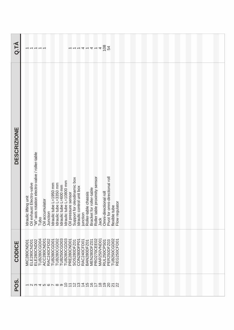
.S
OP
ECI
DO
CE
NOI
ZIR
CS
ED
.Q
TÀ
11
0D
NC
08
2CI
Mcil
uar
dIti
nu
gnitfil
12
10
DN
C0
82
EL
E
evlav-
ortc
elE t
su
ahx
e liO
13
20
DN
C0
82
EL
Eel
bat-r
ellor /
evlav-
ortc
ele
noit
ator
sixa-”
W“1
44
0D
GC
08
2B
UT
ob
uT
15
10
DN
C0
82
CC
Ar
otal
um
uc
ca li
O1
62
0D
FC
04
2C
AR
noit
cn
uJ
71
0D
GC
08
2B
UT
cilu
ardI
mm
05
91
=L
eb
ut 8
20
DG
C0
82
BU
Tcil
uar
dIm
m 0
53
3=
L e
but
93
0D
GC
05
2B
UT
cilu
ardI
mm
00
6=
L e
but
01
30
DG
C0
82
BU
Tcil
uar
dIm
m 0
08
01
=L
eb
ut 1
11
0D
NC
08
2E
RP
ro
sn
es
eru
ss
erp li
O1
21
10
ZF
D0
82
SO
S r
of tro
pp
uS
cim
ani
do
elo
xo
b 1
31
10
PF
D0
82
NO
Ccil
uar
dIx
ob ti
nu l
ortn
oc
14
11
0D
FC
04
2C
AR
noit
cn
uj4
51
10
ZF
D0
82
NA
Bsi
ss
ah
c el
bat-r
ello
R1
61
10
ZF
D0
82
NE
Mel
bat-r
ellor r
of te
kc
arB
47
12
0E
EC
07
2O
RP
ro
sn
es yti
mixor
p el
bat r
ello
R1
81
10
DN
V0
52
RA
Mk
ca
J4
91
10
SP
C0
52
LU
Rll
or la
noit
ceri
d-in
mO
80
10
23
0Z
FD
05
2R
EP
llor l
an
oitc
erid-i
nm
o rof t
oviP
45
12
20
DG
C0
52
BU
Te
but
elbix
elf2
21
0D
FC
05
2G
ER
rot
alu
ger
wol
F


LIMITED WARRANTY CERTIFICATE
BRIDGE SAW mod. ABS/CE
Achilli s.r.l. war ran ties the ex cel lent qual ity and per fect op er a tion of the ABS/CE ma -chine un der the fol low ing conditions:
1. The war ranty is valid for a pe riod of 12 months from the date of sale to the end user.
2. Achilli un der takes to re pair or re place free of charge any me chan i cal part proven tohave a man u fac tur ing de fect af ter be ing in spected by its tech ni cians, while elec tri caland elec tronic com po nents are cov ered by war ranty only if the de fects are ac knowl -edged as such by the respective manufacturers.
3. The war ranty is no lon ger valid if the ma chine or parts of it are mod i fied or al teredby un au tho rized per son nel.
4. The war ranty is not valid for any break age or mal func tion caused by poor main te -nance or in cor rect ma chine op er a tion.
5. Freight or pack ing ex penses for re turn ing parts to the fac tory for re pair or re place -ment and for their re place ment are pay able by the client.
ACHILLI S.R.L.
DEALER’S STAMP AND SIGNATURE
SERIAL No.
DATE OF SALE