abrasive waterjet turning
DESCRIPTION
abrasive water jet machiningTRANSCRIPT

120 Int. J. Machining and Machinability of Materials, Vol. 3, Nos. 1/2, 2008
Copyright © 2008 Inderscience Enterprises Ltd.
Influence of jet impact angle on part geometry in abrasive waterjet turning of aluminium alloys
R. Manu and N. Ramesh Babu* Department of Mechanical Engineering, Indian Institute of Technology Madras, Chennai 600 036, India Fax: +91-44-2257-5705 E-mail: [email protected] E-mail: [email protected] *Corresponding author
Abstract: This paper covers the investigations conducted to study the influence of jet impact angle on the geometry of part produced by Abrasive Waterjet (AWJ) turning process. Preliminary investigations were conducted on a specially designed cylindrical test specimen to examine the influence of jet impact angle and other process parameters on the depth of penetration of AWJs into the material. Based on the results of these investigations, the set of conditions suitable for efficient material removal were determined. The same conditions were chosen for turning of cylindrical parts with AWJs with a view to analyse the influence of these conditions on the material removal and the geometry of part produced. The material removal was characterised by the reduction in the diameter of part, and the geometry of part was assessed by means of roundness error and finish on the surface of part turned with AWJs.
Keywords: Abrasive Waterjets; part geometry; turning; jet penetration depth.
Reference to this paper should be made as follows: Manu, R. and Babu, N.R. (2008) ‘Influence of jet impact angle on part geometry in abrasive waterjet turning of aluminium alloys’, Int. J. Machining and Machinability of Materials, Vol. 3, Nos. 1/2, pp.120–132.
Biographical notes: R. Manu is a Doctoral student in the Manufacturing Engineering Section, Department of Mechanical Engineering at Indian Institute of Technology, Chennai. He graduated in Mechanical Engineering from the University of Kerala and obtained his Post-Graduate degree in Manufacturing Engineering from the Anna University, Chennai. He is presently a Senior Lecturer in the Department of Mechanical Engineering at National Institute of Technology, Calicut, Kerala, India. His areas of interest include non-traditional machining, materials science and computer-aided design and manufacturing.
N. Ramesh Babu is a Professor in the Department of Mechanical Engineering at Indian Institute of Technology, Chennai. He received his Bachelor of Technology (BTech) degree with distinction in 1978 from the Jawaharlal Nehru Technological University, Hyderabad; his Master of Engineering (ME) degree in Mechanical Engineering in 1980 from Indian Institute of Science, Bangalore and his PhD in 1989 from the Indian Institute of Technology, Chennai. His current research interests include manufacturing processes, modelling and simulation of manufacturing processes and systems, computer-aided manufacturing and applications of artificial intelligence techniques in manufacturing. He has published more than 100 papers in refereed journals and conference proceedings.

Influence of jet impact angle on part geometry 121
1 Introduction
Abrasive Waterjet Machining (AWJM) is a versatile process capable of machining almost any material without causing much thermal damage to the materials and producing a reasonable finish on the surface machined (Hashish, 1987). Recent efforts include the application of Abrasive Waterjets (AWJ) for turning of cylindrical parts by traversing the jet along the radial and axial directions of rotating workpiece. Attempts made on AWJ turning include the turning of long and small diameter parts and the production of threads on difficult-to-machine materials like ceramics, composites, glass, etc. (Kovacevic et al., 1997). Most of these efforts are experimental in nature and are parametric studies. Hashish (1987) employed high velocity AWJs for turning of various materials like aluminium, glass and magnesium boron carbide in order to study the influence of AWJ process parameters on the waviness and roughness produced on the turned part. Ansari et al. (1992) conducted a visualisation study to understand the macromechanics of AWJ turning process. It was reported that the removal of material takes place from the face of workpiece instead of from the circumference of workpiece. Ansari and Hashish (1995) investigated the influence of various parameters on volume removal trends in AWJ turning. It was reported that the volume of material removed in turning is almost similar to that noticed in cutting. Further, the material removal rates in turning are limited by either volume sweep rate limit or AWJ limit. Attempts made by Hashish and Stewart (2000) and Hashish (2001) on precision turning showed that the accuracy of part turned by AWJs is affected by jet trail back and jet deflection. Recently, Zhong and Han (2002) studied the influence of process parameters on the quality of glass part turned with AWJs. This study clearly showed that low traverse rate of jet and high rotational speed of workpiece resulted in lower values of roughness and waviness on the surface of turned part.
On the contrary, the attempts made on modelling of AWJ turning process are very much limited. These attempts are mostly empirical in nature and are based on a large amount of experimental data (Henning, 1999). Zeng et al. (1994) developed a regression based semi-empirical approach for predicting the depth of cut when process parameters like water pressure, traverse rate, abrasive mass flow rate, workpiece diameter, orifice diameter and focusing tube diameter are known. Ansari and Hashish (1992) suggested an analytical model that relates the actual volume swept by the jet to the volume of material removed. Using this model, the final diameter of turned part was predicted when a part with certain initial diameter was turned with a given set of AWJ process parameters. This model is an adaptation of the model proposed by Hashish (1989) for linear cutting of materials with AWJs. It made use of Finnie’s theory of erosion for estimating the cutting wear depth achieved with shallow angles of impact of jet and Bitter’s theory of erosion for estimating the deformation wear depth obtained with abrasive particles impacting the work material at large angles. The total depth of cut thus computed is used to predict the final diameter of turned part.
It is well-known that the angle of impact of jet on the work surface influences the results of erosion process (Bitter, 1963a,b; Finnie, 1960; Hashish, 1993; Venugopal Reddy and Sundararajan, 1986). While turning of parts with AWJs, the angle of impact of jet changes continuously due to a continuous change in the diameter of workpiece. This particular change in the angle of impact of jet on the part surface influences the magnitude of material removal. Apart from this, the manner of manipulation of jet against the work surface influences the results achieved with this process. Hashish and
122 R. Manu and N.R. Babu
Stewart (2000) and Hashish (2001) suggested two different strategies for face turning of parts with AWJs. In the first one, the jet is placed either at the top dead centre or at any other radial location with respect to the workpiece for slotting or facing of parts. In the second method, the jet is moved in the direction perpendicular to the axis of workpiece for facing of part. Though these studies have provided some insight into AWJ turning process, there was no attempt to systematically analyse the influence of jet impact location on the volume of material removed and the topography generated on the parts turned with AWJs. Thus, the present work attempts to study the influence of jet impact angle on a cylindrical workpiece in order to assess the volume removal trends and finish obtained on the parts turned with AWJs.
2 Experimental work
In order to analyse the influence of jet impact location on material removal trends and the nature of surface generated in AWJ tuning, the following methodology was adopted.
• the influence of jet impact angle and other parameters such as water pressure and jet traverse rate on the depth of penetration of jet on a cylindrical surface was studied by using a specially designed cylindrical specimen
• the nature of geometry produced in turning by AWJ impacting the cylindrical part with different impact angles was analysed.
To examine the influence of jet impact angle on the depth of penetration of AWJ on cylindrical part, it is necessary to conduct the turning test on a cylindrical specimen of certain initial diameter with each impact angle of jet. To realise different impact angles of jet, either specimens of different diameters have to be chosen or the jet is to be positioned at different radial locations on the cylindrical part. This requires a large number of samples to be prepared for experimentation. It is usual to conduct experiments on a trapezoidal shaped test specimen for determining the maximum penetration of jet into the material in AWJ cutting (Chakravarthy and Babu, 2000). In order to conduct the experiments similar to AWJ cutting for assessing the penetration ability of AWJs in turning of parts, a specimen, shown in Figure 1, was specially designed and fabricated. This will avoid the need for multiple cylindrical work pieces for experimentation.
In contrast to AWJ slab cutting where the jet generally strikes the material at normal impact angles, the jet strikes the cylindrical surface at different impact angles in AWJ turning. The exact angle of impact of jet on the surface depends on the diameter of workpiece and the radial position of jet with reference to the workpiece centre-line. When the jet is positioned above the location ‘E’ on the work surface, it is equivalent to the normal impact of jet. When the jet is located above the point ‘D’ on the work surface, it strikes the surface at an angle α with respect to the tangent to the cylindrical surface at that point. For any given radial location of jet with reference to the specimen centre-line, the jet impact angle will be constant along the length of the specimen. When the jet moves along the length of the specimen, the jet penetrates into the wedge shaped specimen up to a particular depth depending on its energy. Beyond this depth, the jet rebounds due to its inability, that is, due to insufficient energy, to penetrate further into the material. With any given set of AWJ parameters, the maximum depth of penetration of jet into the specimen is known by observing the bouncing of the jet. The maximum

Influence of jet impact angle on part geometry 123
penetration of jet (d) into the material with any particular jet impact angle is determined from the measured length of cut along the slant surface, AC using the relation.
sin(20)d AC= (1)
The experiments were conducted on 6063-T6 aluminium alloy specimens with an injection type AWJ cutting machine capable of generating water pressure in the range of 60–360 MPa with a rated discharge of 2.2 l/min. Waterjet orifice of 0.25 mm diameter and focusing tube of 0.76 mm diameter were employed in the cutting head. Garnet with a mesh size of 80 was used as the abrasive material.
Figure 1 Specially designed test specimen for jet penetration studies
Preliminary experimentation made use of L9 Orthogonal Array (L9 OA) based on Taguchi’s Design of Experiments (DOE). The DOE approach ensures that sufficient data is acquired using the minimum number of experiments to build statistical models for predicting the performance of any process. The experiments were conducted on the test specimen by varying the water pressure, impact angle and jet traverse rate in three levels. Table 1 shows the values chosen for different levels of each of the parameters along with the values chosen for other parameters. The allocation of parameters for conducting the experiments according to L9 OA is given in Table 2. With each set of parameters, the experiment was conducted on the specimen and the maximum depth of penetration was determined using the relation given in the Equation (1). This study was essentially conducted to analyse the variation in the depth of penetration with different parameters and then to identify the optimal set of parameters that can maximise the material removal by way of maximising the penetration of jet into the material.
Once the conditions for maximum material removal are known, these conditions were chosen for conducting the turning experiments on cylindrical specimen. To conduct the turning experiments with AWJs, a special attachment, shown in Figure 2, was developed. It consists of a four jaw chuck to hold the workpiece. The chuck is rotated by a shaft driven by a stepper motor. The drive shaft is supported on two ball bearings. The
124 R. Manu and N.R. Babu
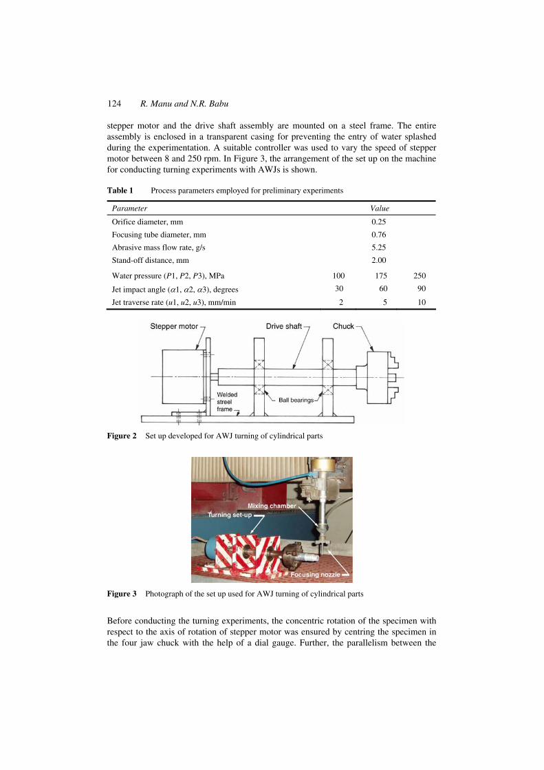
stepper motor and the drive shaft assembly are mounted on a steel frame. The entire assembly is enclosed in a transparent casing for preventing the entry of water splashed during the experimentation. A suitable controller was used to vary the speed of stepper motor between 8 and 250 rpm. In Figure 3, the arrangement of the set up on the machine for conducting turning experiments with AWJs is shown.
Table 1 Process parameters employed for preliminary experiments
Parameter Value
Orifice diameter, mm 0.25
Focusing tube diameter, mm 0.76
Abrasive mass flow rate, g/s 5.25
Stand-off distance, mm 2.00
Water pressure (P1, P2, P3), MPa 100 175 250
Jet impact angle (α1, α2, α3), degrees 30 60 90
Jet traverse rate (u1, u2, u3), mm/min 2 5 10
Figure 2 Set up developed for AWJ turning of cylindrical parts
Figure 3 Photograph of the set up used for AWJ turning of cylindrical parts
Before conducting the turning experiments, the concentric rotation of the specimen with respect to the axis of rotation of stepper motor was ensured by centring the specimen in the four jaw chuck with the help of a dial gauge. Further, the parallelism between the
Influence of jet impact angle on part geometry 125
axis of rotation of the specimen and the traverse direction of jet was ensured by touching the periphery of the rotating specimen with low pressure waterjet and then moving it along the axial direction of the rotating specimen. This is done to minimise form errors that can arise due to misalignment between the jet and rotating workpiece.
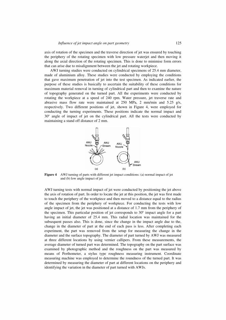
AWJ turning studies were conducted on cylindrical specimens of 25.4 mm diameter, made of aluminium alloy. These studies were conducted by employing the conditions that gave maximum penetration of jet into the test specimen. As indicated earlier, the purpose of these studies is basically to ascertain the suitability of these conditions for maximum material removal in turning of cylindrical part and then to examine the nature of topography generated on the turned part. All the experiments were conducted by rotating the workpiece at a speed of 240 rpm. Water pressure, jet traverse rate and abrasive mass flow rate were maintained at 250 MPa, 2 mm/min and 5.25 g/s, respectively. Two different positions of jet, shown in Figure 4, were employed for conducting the turning experiments. These positions indicate the normal impact and 30° angle of impact of jet on the cylindrical part. All the tests were conducted by maintaining a stand off distance of 2 mm.
Figure 4 AWJ turning of parts with different jet impact conditions: (a) normal impact of jet and (b) low angle impact of jet
AWJ turning tests with normal impact of jet were conducted by positioning the jet above the axis of rotation of part. In order to locate the jet at this position, the jet was first made to touch the periphery of the workpiece and then moved to a distance equal to the radius of the specimen from the periphery of workpiece. For conducting the tests with low angle impact of jet, the jet was positioned at a distance of 1.7 mm from the periphery of the specimen. This particular position of jet corresponds to 30° impact angle for a part having an initial diameter of 25.4 mm. This radial location was maintained for the subsequent passes also. This is done, since the change in the impact angle due to the, change in the diameter of part at the end of each pass is less. After completing each experiment, the part was removed from the setup for measuring the change in the diameter and the surface topography. The diameter of part turned by AWJ was measured at three different locations by using vernier callipers. From these measurements, the average diameter of turned part was determined. The topography on the part surface was examined by photographic method and the roughness on the part was measured by means of Perthometer, a stylus type roughness measuring instrument. Coordinate measuring machine was employed to determine the roundness of the turned part. It was determined by measuring the diameter of part at different locations on the periphery and identifying the variation in the diameter of part turned with AWJs.

126 R. Manu and N.R. Babu
3 Results and discussion
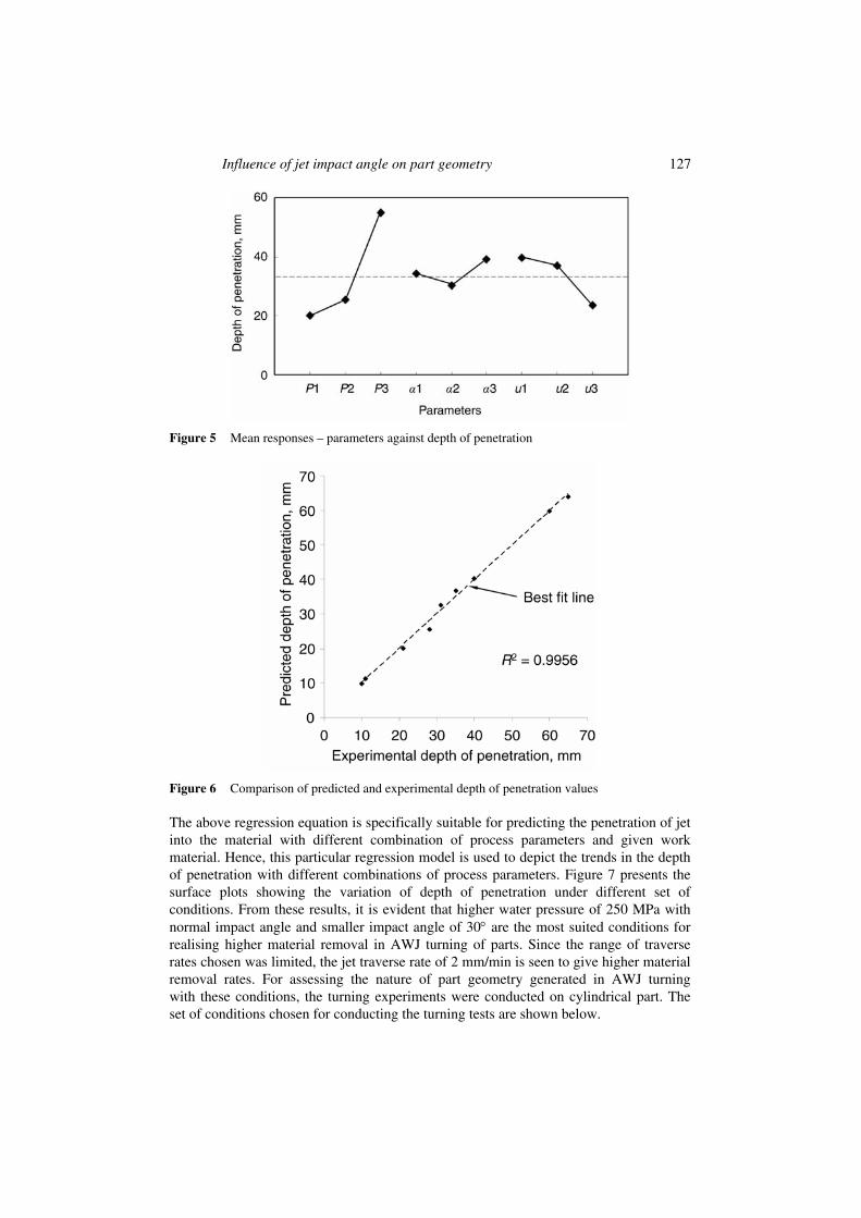
Table 2 presents the depth of penetration of jet into the specimen with different conditions chosen for experimentation. From these results, it can be observed that the water pressure and jet impact angles are found to influence the jet penetration into the material. AWJ with higher pressures penetrated into the specimen to a larger extent irrespective of the impact angle of the jet. With the highest pressure of 250 MPa and normal impact angle, the AWJ penetrated into the specimen to the maximum extent. Interestingly, lower pressures with smaller impact angle of 30° also yielded a reasonably higher penetration of jet into the material. The data generated from the experiments is further subjected to mean response analysis to study the influence of each parameter separately. Figure 5 shows the mean response of different parameters such as water pressure, jet impact angle and jet traverse rate on the depth of penetration. From the results presented in the figure, it is evident that higher water pressure of 250 MPa, impact angles of 30° and 90°, lowest traverse rate of 2 mm/min. are seen to be favourable for achieving higher material removal rates with AWJs.
Table 2 Depth of penetration obtained for different set of conditions according to L9 OA experimentation
S. No. Water pressure, (P) MPa
Jet impact angle, (α) degrees
Jet traverse rate, (u) mm/min
Depth of penetration (d) mm
1 100 30 2 28
2 100 60 5 11
3 100 90 10 21
4 175 30 5 35
5 175 60 10 10
6 175 90 2 31
7 250 30 10 40
8 250 60 2 60
9 250 90 5 65
The data generated from the experiments was used to develop a regression model that relates the depth of penetration to water pressure, jet impact angle and jet traverse rate. This model was developed using the statistical software SPSS version 9.05 and is given by
3.76 3.26 0.7822.844 0.0401 0.0013 0.067 0.0586d P u P u Pu uα α α− −= + + − − (2)
with a coefficient of correlation, R2 value of 0.9959 and adjusted R2 statistic of 0.9672, where d is the depth of penetration in mm, P is the water pressure in MPa, u is the jet traverse rate in mm/min and α is jet impact angle in degrees. The results predicted with this model show excellent correlation with experimentally obtained values (Figure 6).
Influence of jet impact angle on part geometry 127
Figure 5 Mean responses – parameters against depth of penetration
Figure 6 Comparison of predicted and experimental depth of penetration values
The above regression equation is specifically suitable for predicting the penetration of jet into the material with different combination of process parameters and given work material. Hence, this particular regression model is used to depict the trends in the depth of penetration with different combinations of process parameters. Figure 7 presents the surface plots showing the variation of depth of penetration under different set of conditions. From these results, it is evident that higher water pressure of 250 MPa with normal impact angle and smaller impact angle of 30° are the most suited conditions for realising higher material removal in AWJ turning of parts. Since the range of traverse rates chosen was limited, the jet traverse rate of 2 mm/min is seen to give higher material removal rates. For assessing the nature of part geometry generated in AWJ turning with these conditions, the turning experiments were conducted on cylindrical part. The set of conditions chosen for conducting the turning tests are shown below.

128 R. Manu and N.R. Babu
First set of conditions: Water pressure (P): 250 MPa
Jet traverse rate (u): 2 mm/min
Jet impact angle (α): 90o
Second set of conditions: Water pressure (P): 250 MPa
Jet traverse rate (u): 2 mm/min Jet impact angle (α): 30°
Figure 7 Variation in depth of penetration predicted using regression model under various conditions of pressure, traverse rate and impact angle
Figure 8 shows the photograph of the regions on the parts turned with the jet incident at normal and low impact angles. From this, it can be observed that the topography on the part turned with normal impact of AWJ was quite rough. In contrast to this, the smaller angles of impact of jet produced a reasonably good surface on the part. In order to assess the exact nature of geometry generated on the part with different angles of impact of jet, the various parameters such as the radial depth of cut, volumetric material removal rate, surface finish and roundness were used. Table 3 presents the variation of these parameters observed on the parts turned using different impact angles of jet. The Volume Removal Rate (VRR) is determined from the kerf area and jet traverse rate (u). The kerf area for each pass is calculated from the initial diameter (Di) and final diameter (Df) of part. VRR for any particular pass can be determined by the relation
( )2 2i fVRR 4 D D uπ= − (3)
With the normal impact of jet, the diameter of cylindrical specimen is reduced from 25.4 to 23.5 mm in a single pass. With a jet impact angle of 30°, a similar reduction in the diameter of part took place after three passes. This clearly suggests the choice of normal impact of jet for efficient removal of material from the workpiece. However, this particular impact angle of jet produced a rough and wavy surface on the part. Further, the

Influence of jet impact angle on part geometry 129
roundness observed on the part turned with normal impact of AWJ is also high. On the contrary, lower angles of impact of jet resulted in a better surface with reasonable finish and roundness. But, the efficiency of material removal is quite low. All the above clearly indicate the possibility of employing normal impact angles for rough turning of parts and lower impact angles for finish turning of parts with AWJs.
Figure 8 Photograph showing the topography generated on AWJ turned aluminium specimens with different angles of impact (a) normal impact (b) low angle impact
A closer look at the results obtained with an impact angle of 30° discloses that the reduction in the diameter of part is relatively less due to lesser rate of material removal in each pass. However, the finish achieved on the turned surface is found to improve with subsequent passes. This can be seen clearly from photograph shown in Figure 9 and the surface roughness values presented in Table 3. A similar trend can also be observed on the roundness of the part. This particular nature of results can be attributed to the variation in the initial diameter of part, spreading of AWJ due to variation in the stand off distance with reduced diameter of part and the impact angle of jet on the part. However, the exact analysis of this behaviour requires a detailed study maintaining the above parameters constant during the experimentation with multipass AWJ turning.
Figure 9 Photograph of part turned with low angle impact (a) single pass, (b) two passes and (c) three passes
From the preliminary studies conducted on the specially designed test specimen and the turning experiments conducted on cylindrical specimen, one can clearly observe that the trends of variation in the depth of penetration with water pressure and jet impact angle are the same. In both cases, higher water pressures and low as well as normal impact angles gave a larger depth of penetration of jet into the material. However, the exact magnitude of material removed in both the situations is considerably different. This can be attributed to the higher relative speed of the jet with respect to the workpiece, in the turning tests. For the cylindrical part of diameter 25.4 mm rotating at 240 rpm, the surface speed is 19151 mm/min. This condition can result in a dwell time of 3 ms for the jet to penetrate into the material. In contrast to this, the cutting experiments on the special test specimen were conducted with 2 mm/min traverse rate which can allow the jet to stay on the material for the duration of 30 sec. Hence, this particular aspect is very important and needs to be investigated further to ascertain the influence of jet traverse rate on the part geometry.

130 R. Manu and N.R. Babu

Influence of jet impact angle on part geometry 131
4 Conclusions
The present work attempted to study the influence of jet impact angle on the depth of penetration and surface topography on cylindrical parts turned by AWJs. The preliminary investigations conducted on the specially designed test specimen revealed that higher water pressure combined with low as well as normal impact angle of jet resulted in large penetration of the jet into the material. The exact influence of these parameters on material removal in actual turning was found to be in agreement with the above observations. However, the normal impact of jet with higher water pressure yielded higher material removal with a poor surface geometry in terms of roundness and surface roughness on the turned part. But, an impact angle of 30° with higher water pressure produced better finish on the turned part with lesser material removal. These preliminary observations clearly suggest the possibility of employing normal impact of jet for rough turning and smaller impact angles for finish turning of cylindrical parts. With a suitable combination of jet impact angle and other parameters of AWJ turning, it is possible to realise efficient material removal in generating the desired part geometry with AWJ tuning. However, this requires detailed investigations to examine the material removal rates and surface quality with different combinations of jet impact angles and other parameters for AWJ turning of parts.
References
Ansari, A.I. and Hashish, M. (1992) ‘On the modeling of abrasive waterjet turning’, Proceedings of 11th International Conference on Jet Cutting Technology, St. Andrews, Scotland, 8–10 September, pp.555–576.
Ansari, A.I. and Hashish, M. (1995) ‘Effect of abrasive waterjet parameters on volume removal trends in turning’, ASME Journal of Engineering for Industry, Vol. 117, No. 4, pp.475–484.
Ansari, A.I., Hashish, M. and Ohadi, M.M. (1992) ‘Flow visualization study of the macromechanics of abrasive waterjet turning’, Experimental Mechanics, Vol. 32, No. 4, pp.358–364.
Bitter, J.G.A. (1963a) ‘A study of erosion phenomena – part I’, Wear, Vol. 6, No. 1, pp.5–21.
Bitter, J.G.A. (1963b) ‘A study of erosion phenomena – part II’, Wear, Vol. 6, No. 3, pp.169–190.
Chakravarthy, P.S. and Babu, R.N. (2000) ‘A hybrid approach for selection of optimal process parameters in abrasive waterjet cutting’, Proceedings of Institution of Mechanical Engineers, Part B: Journal of Engineering Manufacture, Vol. 214, No. 9, pp.781–791.
Finnie, I. (1960) ‘Erosion of surfaces by solid particles’, Wear, Vol. 3, No. 2, pp.87–103.
Hashish, M. (1987) ‘Turning with abrasive waterjets – a first investigation’, ASME Journal of Engineering for Industry, Vol. 109, No. 4, pp.281–290.
Hashish, M. (1989) ‘A model for AWJ machining’, ASME Journal of Engineering Materials and Technology, Vol. 111, No. 2, pp.154–162.
Hashish, M. (1993) ‘The effect of beam angle in abrasive waterjet machining’, ASME Journal of Engineering for Industry, Vol. 115, No. 1, pp.51–56.
Hashish, M. (2001), ‘Macro characteristics of AWJ turned surfaces’, Proceedings of 2001 WJTA American Waterjet Conference, Minneapolis, Minnesota, 18–21 August, Paper No. 4, pp.1–14.
Hashish, M. and Stewart, J. (2000) ‘Observations on precision turning with AWJ’, Proceedings of 15th International Conference on Jet Cutting Technology, Ronneby, Sweden, 6–8 September, pp.367–380.

132 R. Manu and N.R. Babu
Henning, A. (1999) ‘Modelling of turning operation for abrasive waterjets’, Proceedings of 10th American Waterjet Conference, Houston, Texas, 14–17 August, pp.795–810.
Kovacevic, R., Hashish, M., Mohan, R., Ramulu, M., Kim, T.J. and Geskin, E.S. (1997) ‘State of the art of research and development in abrasive waterjet machining’, ASME Journal of Manufacturing Science and Engineering, Vol. 119, pp.776–785.
Venugopal Reddy, A. and Sundararajan, G. (1986) ‘Erosion behaviour of ductile materials with a spherical non-friable erodent’, Wear, Vol. 111, No. 3, pp.313–323.
Zeng, J., Wu, S. and Kim, T.J. (1994) ‘Development of a parameter prediction model for abrasive waterjet turning’, Proceedings of 12th International Conference on Jet Cutting Technology, Rouen, France, 25–27 October, pp.601–617.
Zhong, Z.W. and Han, Z.Z. (2002) ‘Turning of glass with abrasive waterjet’, Materials and Manufacturing Processes, Vol. 17, No. 3, pp.330–349.