above the ground plane arduino program...
TRANSCRIPT
62CO
LUM
NS
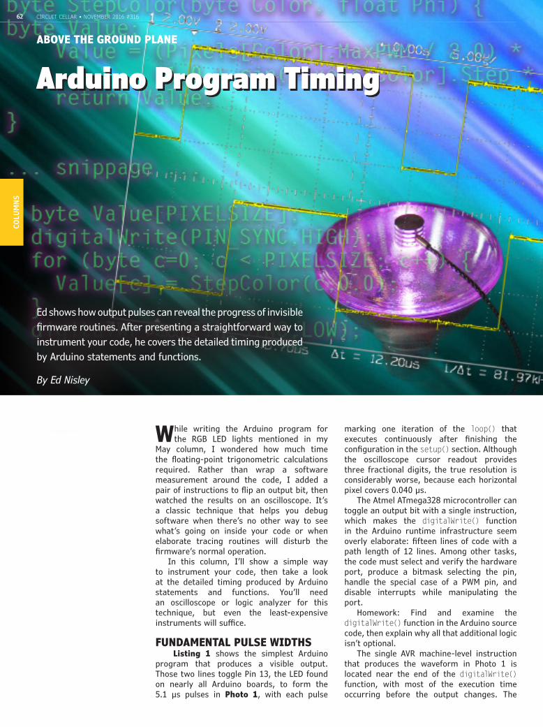
Ed shows how output pulses can reveal the progress of invisible firmware routines. After presenting a straightforward way to instrument your code, he covers the detailed timing produced by Arduino statements and functions.
By Ed Nisley
Arduino Program Timing
CIRCUIT CELLAR • NOVEMBER 2016 #316
While writing the Arduino program for the RGB LED lights mentioned in my
May column, I wondered how much time the floating-point trigonometric calculations required. Rather than wrap a software measurement around the code, I added a pair of instructions to flip an output bit, then watched the results on an oscilloscope. It’s a classic technique that helps you debug software when there’s no other way to see what’s going on inside your code or when elaborate tracing routines will disturb the firmware’s normal operation.
In this column, I’ll show a simple way to instrument your code, then take a look at the detailed timing produced by Arduino statements and functions. You’ll need an oscilloscope or logic analyzer for this technique, but even the least-expensive instruments will suffice.
FUNDAMENTAL PULSE WIDTHS Listing 1 shows the simplest Arduino
program that produces a visible output. Those two lines toggle Pin 13, the LED found on nearly all Arduino boards, to form the 5.1 µs pulses in Photo 1, with each pulse
marking one iteration of the loop() that executes continuously after finishing the configuration in the setup() section. Although the oscilloscope cursor readout provides three fractional digits, the true resolution is considerably worse, because each horizontal pixel covers 0.040 µs.
The Atmel ATmega328 microcontroller can toggle an output bit with a single instruction, which makes the digitalWrite() function in the Arduino runtime infrastructure seem overly elaborate: fifteen lines of code with a path length of 12 lines. Among other tasks, the code must select and verify the hardware port, produce a bitmask selecting the pin, handle the special case of a PWM pin, and disable interrupts while manipulating the port.
Homework: Find and examine the digitalWrite() function in the Arduino source code, then explain why all that additional logic isn’t optional.
The single AVR machine-level instruction that produces the waveform in Photo 1 is located near the end of the digitalWrite() function, with most of the execution time occurring before the output changes. The
ABOVE THE GROUND PLANE
circuitcellar.com 63CO
LUM
NS
high part of the pulse therefore includes the short tail end of the first digitalWrite() and the longer beginning of the second, but the output pulse width shows the execution time through the complete function.
The 16 MHz crystal oscillator on the Arduino UNO clone board I used for these measurements produces a 62.5 ns instruction cycle, so each 5 µs pulse contains about 80 cycles. Most AVR arithmetic instructions require one or two cycles, branches require two or three, and subroutine CALL/RETURN pairs soak up eight, so assuming 1.6 cycles/instruction for short subroutines seems reasonable and allows you to figure the results in your head: 10 instructions per microsecond. That means the compiler translates the dozen high-level lines of code in the digitalWrite() function into 50 machine-level instructions.
Homework: Examine the compiler’s machine-level output to determine the actual number of instructions.
The low part of the pulse occurs as execution continues through the Arduino infrastructure as the loop() returns control to the first digitalWrite() line, adding 400 ns behind the scenes. That’s only six machine cycles, perhaps three or four machine instructions, and not much overhead at all.
TRACING A MISSING PULSETriggering your oscilloscope on the signal
produced by Listing 1 should produce a steady display, but you’ll see “ghost” traces that seem to show missing pulses. Setting the trigger to produce single sweeps will eventually produce a display similar to Photo 2, with an obviously missing pulse.
Because the program’s logic (if you can call it that) lacks branches that could omit a pulse, the problem must lie elsewhere. Carefully examining the pulse timings shows that there’s not quite enough time for another pulse in that gap, which means the extended time came from a delay, rather than an omission.
The Arduino infrastructure includes a millis() function that reports the elapsed time in milliseconds since the microcontroller emerged from its most recent reset. A timer interrupt occurs every millisecond, with the interrupt handler updating a counter that the millis() function returns to the caller in a four byte unsigned long integer.
Because the loop() in Listing 1 iterates every 10.4 µs, the timer interrupt will occur once in every 96 pulses, stretching either the high or low part of the pulse. The advantage of an oscilloscope should be obvious: a problem that occurs 1% of the time might not appear amid all the “correct” values shown by a simple software measurement.
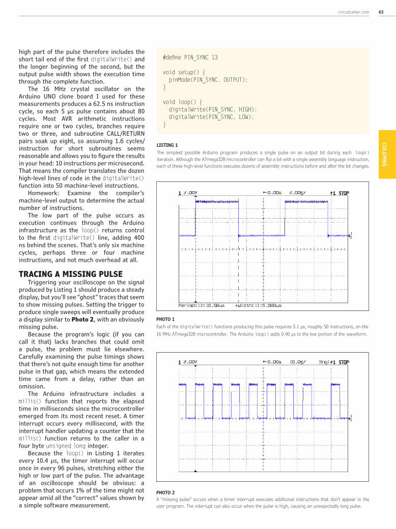
LISTING 1The simplest possible Arduino program produces a single pulse on an output bit during each loop() iteration. Although the ATmega328 microcontroller can flip a bit with a single assembly language instruction, each of these high-level functions executes dozens of assembly instructions before and after the bit changes.
#define PIN_SYNC 13
void setup() { pinMode(PIN_SYNC, OUTPUT);}
void loop() { digitalWrite(PIN_SYNC, HIGH); digitalWrite(PIN_SYNC, LOW);}
PHOTO 1 Each of the digitalWrite() functions producing this pulse requires 5.1 µs, roughly 50 instructions, on the 16 MHz ATmega328 microcontroller. The Arduino loop() adds 0.40 µs to the low portion of the waveform.
PHOTO 2 A “missing pulse” occurs when a timer interrupt executes additional instructions that don’t appear in the user program. The interrupt can also occur when the pulse is high, causing an unexpectedly long pulse.
CIRCUIT CELLAR • NOVEMBER 2016 #31664CO
LUM
NS
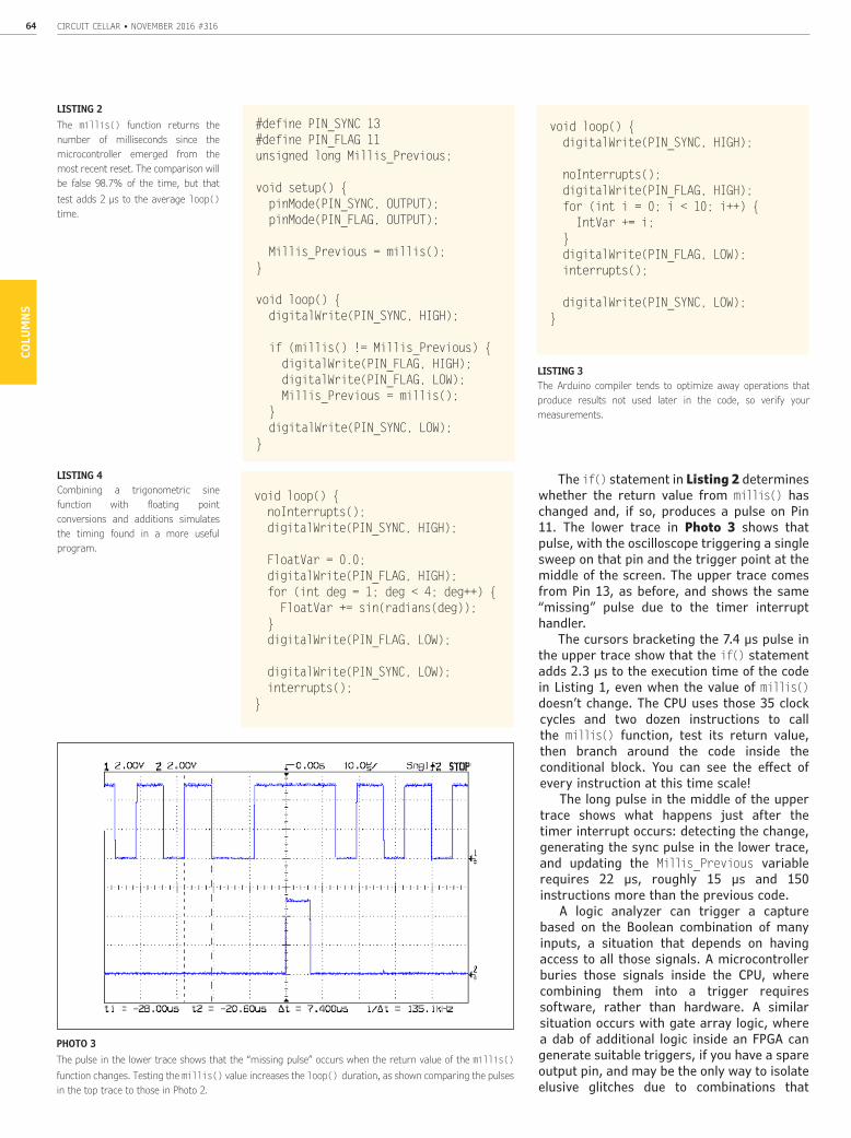
The if() statement in Listing 2 determines whether the return value from millis() has changed and, if so, produces a pulse on Pin 11. The lower trace in Photo 3 shows that pulse, with the oscilloscope triggering a single sweep on that pin and the trigger point at the middle of the screen. The upper trace comes from Pin 13, as before, and shows the same “missing” pulse due to the timer interrupt handler.
The cursors bracketing the 7.4 µs pulse in the upper trace show that the if() statement adds 2.3 µs to the execution time of the code in Listing 1, even when the value of millis() doesn’t change. The CPU uses those 35 clock cycles and two dozen instructions to call the millis() function, test its return value, then branch around the code inside the conditional block. You can see the effect of every instruction at this time scale!
The long pulse in the middle of the upper trace shows what happens just after the timer interrupt occurs: detecting the change, generating the sync pulse in the lower trace, and updating the Millis_Previous variable requires 22 µs, roughly 15 µs and 150 instructions more than the previous code.
A logic analyzer can trigger a capture based on the Boolean combination of many inputs, a situation that depends on having access to all those signals. A microcontroller buries those signals inside the CPU, where combining them into a trigger requires software, rather than hardware. A similar situation occurs with gate array logic, where a dab of additional logic inside an FPGA can generate suitable triggers, if you have a spare output pin, and may be the only way to isolate elusive glitches due to combinations that
LISTING 2The millis() function returns the number of milliseconds since the microcontroller emerged from the most recent reset. The comparison will be false 98.7% of the time, but that test adds 2 µs to the average loop() time.
#define PIN_SYNC 13#define PIN_FLAG 11unsigned long Millis_Previous;
void setup() { pinMode(PIN_SYNC, OUTPUT); pinMode(PIN_FLAG, OUTPUT);
Millis_Previous = millis();}
void loop() { digitalWrite(PIN_SYNC, HIGH);
if (millis() != Millis_Previous) { digitalWrite(PIN_FLAG, HIGH); digitalWrite(PIN_FLAG, LOW); Millis_Previous = millis(); } digitalWrite(PIN_SYNC, LOW);}
void loop() { digitalWrite(PIN_SYNC, HIGH);
noInterrupts(); digitalWrite(PIN_FLAG, HIGH); for (int i = 0; i < 10; i++) { IntVar += i; } digitalWrite(PIN_FLAG, LOW); interrupts();
digitalWrite(PIN_SYNC, LOW);}
LISTING 3 The Arduino compiler tends to optimize away operations that produce results not used later in the code, so verify your measurements.
LISTING 4Combining a trigonometric sine function with floating point conversions and additions simulates the timing found in a more useful program.
void loop() { noInterrupts(); digitalWrite(PIN_SYNC, HIGH);
FloatVar = 0.0; digitalWrite(PIN_FLAG, HIGH); for (int deg = 1; deg < 4; deg++) { FloatVar += sin(radians(deg)); } digitalWrite(PIN_FLAG, LOW);
digitalWrite(PIN_SYNC, LOW); interrupts();}
PHOTO 3 The pulse in the lower trace shows that the “missing pulse” occurs when the return value of the millis() function changes. Testing the millis() value increases the loop() duration, as shown comparing the pulses in the top trace to those in Photo 2.

circuitcellar.com 65CO
LUM
NS
occur so rarely as to be invisible.Homework: Move the statement that
updates Millis_Previous between the two digitalWrite() functions, then measure the change in pulse width to determine the time required to update that variable.
As the number of statements inside the loop() increases, the likelihood that the timer interrupt will occur during the program also increases. This won’t make any difference to most programs, but when you’re watching a pulse on the oscilloscope, you don’t want a timer interrupt disturbing your measurements. The code in the next few examples will disable all interrupts just before raising the timing pulse and enable them after lowering it, forcing the timer interrupt to occur outside the critical section.
INSTRUCTION TIMINGThe code in Listing 3 displays the time
required to execute a for() loop that accumulates the value of the index variable. The 6.7 µs pulse in the lower trace of Photo 4 shows that a single iteration adds 1.6 µs to the 5.1 µs pulse generation time you saw earlier.
Photo 5 shows 10 loop iterations produce a 12.2 µs pulse, 7.1 µs more than the minimum pulse width, for an average iteration time of 0.71 µs. The additional time required by the single iteration in Photo 4 probably comes from setting up the index variable, so a better measurement of the iteration time would come from the difference of the two pulses: 12.2 – 6.7 = 5.5 µs. Dividing that by 9 gives 0.61 µs per iteration.
Homework: Verify that value by plotting elapsed time against iteration count over a useful range.
My first version of this program used a simple assignment inside the loop, but the pulse width remained constant regardless of the number of iterations. It seems the Arduino’s default compiler settings invoke fairly aggressive optimizations, with the result that the code producing a variable you don’t subsequently use will simply vanish. Of course, if your code doesn’t use the variable, you might not notice it was missing, unless you were depending on that code to produce a side effect such as delaying for a specific time. Such optimizations can lead to truly baffling problems that occur only when you don’t add debugging code to examine the missing variables!
Programs running on embedded CPUs that directly control hardware, which is what Arduinos usually do for a living, have different requirements than programs that perform classic data processing. The latter have no particular timing requirements, other
PHOTO 4 The 6.7 µs pulse in the lower trace surrounds one iteration of a for() loop. Because generating the pulse requires 5.1 µs, the loop iteration takes only 1.6 µs.
PHOTO 5Ten iterations of the for() loop require 12.2 µs.
byte StepColor(byte Color, float Phi) {byte Value; Value = (Pixels[Color].MaxPWM / 2.0) * (1.0 + sin(Pixels[Color].Step * Pixels[Color].StepSize + Phi)); return Value;}
... snippage ...
byte Value[PIXELSIZE]; digitalWrite(PIN_SYNC,HIGH); for (byte c=0; c < PIXELSIZE; c++) { Value[c] = StepColor(c,0.0); } digitalWrite(PIN_SYNC,LOW);
LISTING 5Computing the next PWM value for each of three LED colors requires array index operations, floating point arithmetic, and trigonometry. Despite all that, this code executes in half a millisecond on an 8-bit microcontroller.
CIRCUIT CELLAR • NOVEMBER 2016 #31666CO
LUM
NS
than being “fast enough” in their human interactions, so most program optimization techniques assume that the exact timing relation between parts of the program don’t matter. In fact, some optimizations can rearrange sections of the program to reduce the program space or improve the execution time, resulting in a machine-level program that bears little resemblance to the source code’s layout.
Because adding high-level instructions can produce unexpected changes in the low-level execution path, you may find that watching a pulse on an output pin gives you better visibility into the program’s behavior than pondering the variables and registers displayed in a debugger written for an entirely different programming paradigm.
FLOATING POINTSThe Arduino language descends from
C++ and its runtime library supports single-precision floating point variables and operations. Even though the ATmega328 microcontroller ALU remains only eight bits wide and definitely lacks the floating point acceleration hardware found in desktop PCs, your algorithms can still use “real” numbers. Of course, your program remains subject to the usual tradeoffs of a microcontroller: very limited memory and relatively slow computation.
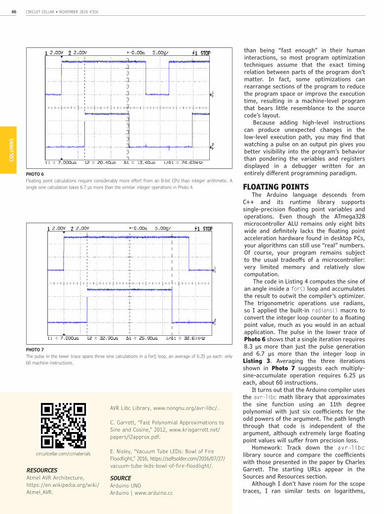
The code in Listing 4 computes the sine of an angle inside a for() loop and accumulates the result to outwit the compiler’s optimizer. The trigonometric operations use radians, so I applied the built-in radians() macro to convert the integer loop counter to a floating point value, much as you would in an actual application. The pulse in the lower trace of Photo 6 shows that a single iteration requires 8.3 µs more than just the pulse generation and 6.7 µs more than the integer loop in Listing 3. Averaging the three iterations shown in Photo 7 suggests each multiply-sine-accumulate operation requires 6.25 µs each, about 60 instructions.
It turns out that the Arduino compiler uses the avr-libc math library that approximates the sine function using an 11th degree polynomial with just six coefficients for the odd powers of the argument. The path length through that code is independent of the argument, although extremely large floating point values will suffer from precision loss.
Homework: Track down the avr-libc library source and compare the coefficients with those presented in the paper by Charles Garrett. The starting URLs appear in the Sources and Resources section.
Although I don’t have room for the scope traces, I ran similar tests on logarithms,
circuitcellar.com/ccmaterials
RESOURCESAtmel AVR Architecture, https://en.wikipedia.org/wiki/Atmel_AVR.
AVR Libc Library, www.nongnu.org/avr-libc/.
C. Garrett, “Fast Polynomial Approximations to Sine and Cosine,” 2012, www.krisgarrett.net/papers/l2approx.pdf.
E. Nisley, “Vacuum Tube LEDs: Bowl of Fire Floodlight,” 2016, https://softsolder.com/2016/07/27/vacuum-tube-leds-bowl-of-fire-floodlight/.
SOURCEArduino UNOArduino | www.arduino.cc
PHOTO 7The pulse in the lower trace spans three sine calculations in a for() loop, an average of 6.25 µs each: only 60 machine instructions.
PHOTO 6 Floating point calculations require considerably more effort from an 8-bit CPU than integer arithmetic. A single sine calculation takes 6.7 µs more than the similar integer operations in Photo 4.

circuitcellar.com 67CO
LUM
NS
exponentials, and other floating point operations, with similar results: they all run much more rapidly than I expected!
TRIGONOMETRIC COLORSListing 5 provides a somewhat more
“real world” measurement than the isolated computations you’ve seen so far. The StepColor() function computes the PWM value for a single LED in an RGB package with a W2812B controller, given the LED identifier Color and a phase angle Phi. The sin() function argument increments from 0.0 through 2π radians, with coefficients taken from an LED state array and using an integer index Step to avoid accumulated floating point errors. The computed Value contains the integer PWM setting equivalent to the raised sine wave’s floating point value, scaled to a desired maximum PWM level that limits the overall brightness. The for() loop calculates the three RGB PWM values for a single RGB LED, so it requires three calls to StepColor().
The lower trace in Photo 8 shows the floating point computations require nearly half a millisecond, with the 5 µs pulse-generation time adding only 1% to the total time. The upper trace goes high just before the computations begin and goes low after sending the new PWM values to the LEDs. The W2812B controller accepts data at 800 kbps, so sending all 24 data bits occupies 30 µs of the additional time.
One of my Hollow State Electronics decorations using this code appeared in my May 2016 column and Photo 9 shows another: an incandescent floodlight topped with a single RGB LED that fills the reflector bowl with slowly changing colors. The finned aluminum cylinder epoxied to the lens resembles a heatsink, but, with the LED dissipating barely 200 mW, it’s really a decorative anchor for the braided sleeve containing the LED power and data wires.
The sine waves driving the three LEDs have mutually prime periods that repeat the same sequence of colors every twelve hours. While it’s not the most stylish nightlight you’ll ever see, it has a certain geeky appeal.
CONTACT RELEASEPrograms running on large systems can
take advantage of software timing and profiling that depend on expansive memory and storage. When your code runs on a microcontroller with an eight bit datapath, a few kilobytes of memory, and not much else, watching it execute on an oscilloscope can reveal problems in real time. Add a few pulses to your code and see how it really works!
PHOTO 8 The floating point calculations that produce the three PWM values for one RGB LED require slightly more than half a millisecond.
PHOTO 9A single knockoff Neopixel illuminates an old incandescent floodlight with slowly changing RGB values computed by floating point sine functions.