abis cdma2000
TRANSCRIPT
8/2/2019 Abis CDMA2000
http://slidepdf.com/reader/full/abis-cdma2000 1/89
3GPP2 A.S0003
Version 1.0.0
Date: March 16, 2000
Abis interface Technical Specification for cdma2000 Spread Spectrum Systems
(A.S0003 : BSC to BTS Interoperability specification (Abis))
COPYRIGHT3GPP2 and its Organizational Partners claim copyright in this document and individualOrganizational Partners may copyright and issue documents or standards publications inindividual Organizational Partner's name based on this document. Requests for reproductionof this document should be directed to the 3GPP2 Secretariat at [email protected] to reproduce individual Organizational Partner's documents should be directed tothat Organizational Partner. See www.3gpp2.org for more information.

8/2/2019 Abis CDMA2000
http://slidepdf.com/reader/full/abis-cdma2000 2/89
R e v is i o n H is t o r y
R e v i s i o n D e s c r i p t i o n D a t e
R e v. 1 . 0 . 0 I n i t ia l P u b l ic a t i on M a r c h 2 0 0 0

8/2/2019 Abis CDMA2000
http://slidepdf.com/reader/full/abis-cdma2000 3/89
1
1
8/2/2019 Abis CDMA2000
http://slidepdf.com/reader/full/abis-cdma2000 4/89
1
1. INTRODUCTION .................................................................................................................................................... 41
2. OBJECTIVES ...........................................................................................................................................................42
2.1 S COPE OF THE DOCUMENT ..................................................................................................................................43
3. GLOSSARY ............................................................................................................................................................... 44
3.1 GLOSSARY ............................................................................................................................................................45
4. NETWORK REFERENCE MODEL AND INTERFACES .......................................................................... 76
4.1 S UPPORT OF USER TRAFFIC CONNECTIONS TO A FRAME SELECTOR FUNCTION .........................................1074.2 S UPPORT OF PAGING CHANNEL MESSAGING ...................................................................................................1084.3 S UPPORT OF ACCESS CHANNEL MESSAGING ..................................................................................................1194.4 S UPPORT OF RADIO FUNCTIONS .......................................................................................................................11104.5 S UPPORT OF BROADCAST SYSTEM INFORMATION FUNCTIONS .....................................................................11114.6 LAYERS 1 & 2 ....................................................................................................................................................1212
4.6.1 Physical Layer Specification (Layer 1)..............................................................................................12134.6.2 Use of ATM (Layer 2) ............................................................................................................................12144.6.3 Field of Application ...............................................................................................................................12154.6.4 ATM Layer...............................................................................................................................................12164.6.5 ATM Adaptation Layer..........................................................................................................................12174.6.6 Network and Transport Protocols .......................................................................................................1418
4.6.6.1 Signaling Connection Transport Protocol Options...........................................................................14194.6.6.2 User Traffic Connection Transport Protocol Options.......................................................................15204.6.6.3 TCP Transport Protocol Usage..........................................................................................................15214.6.6.4 General Use of TCP..........................................................................................................................15224.6.6.5 Use of TCP for the Abis Interface.....................................................................................................1723
4.6.7 IP Network Protocol Usage..................................................................................................................17 24
5. CALL PROCESSING............................................................................................................................................1825
5.1 M OBILE ORIGINATING CALL ...........................................................................................................................19265.2 M OBILE TERMINATED CALL ............................................................................................................................22275.3 C ALL CLEARING ................................................................................................................................................2728
5.3.1 Call Clearing initiated by MS ..............................................................................................................27 295.3.2 Call Clearing initiated by BS/MSC.....................................................................................................29305.3.3 Call Clearing initiated by BTS...............................................................................................................3031
5.4 H ANDOFF ............................................................................................................................................................3232
5.4.1 Soft/Softer Handoff (Intra -BTS)...........................................................................................................32335.4.2 Soft/Softer Handoff (Inter-BTS) ...........................................................................................................3334
5.5 SMS D ELIVERY .................................................................................................................................................35355.5.1 SMS Delivery on the Paging channel .................................................................................................35365.5.2 SMS Delivery on the Access channel..................................................................................................36 375.5.3 SMS Delivery on the Traffic channel to MS.......................................................................................37 385.5.4 SMS Delivery on the Traffic channel from MS..................................................................................3839
8/2/2019 Abis CDMA2000
http://slidepdf.com/reader/full/abis-cdma2000 5/89
2
5.6 T RAFFIC BURST OPERATION ............................................................................................................................3915.6.1 Initial Traffic Burst Example – Abis Connection Not Yet Established..........................................3925.6.2 Subsequent Traffic Burst Example ......................................................................................................423
6. ABIS INTERFACE MESSAGE FORMATS ......................................................................................................444
6.1 A BIS INTERFACE MESSAGE ......................................................................................................................................4456.1.1 Abis-ACH Msg Transfer ..........................................................................................................................4466.1.2 Abis-ACH Msg Transfer Ack ..................................................................................................................47 76.1.3 Abis-PCH Msg Transfer ..........................................................................................................................4886.1.4 Abis-PCH Msg Transfer Ack ..................................................................................................................5096.1.5 Abis-BTS Setup .........................................................................................................................................52106.1.6 Abis-BTS Setup Ack..................................................................................................................................58116.1.7 Abis-BTS Release .....................................................................................................................................61126.1.8 Abis-BTS Release Ack..............................................................................................................................62136.1.9 Abis-Burst Request ...................................................................................................................................63146.1.10 Abis-Burst Response ................................................................................................................................72156.1.11 Abis-Burst Commit ...................................................................................................................................77 166.1.12 Abis-Connect.............................................................................................................................................82176.1.13 Abis-Connect Ack .....................................................................................................................................82186.1.14 Abis-Remove..............................................................................................................................................82196.1.15 Abis-Remove Ack ......................................................................................................................................82206.1.16 Abis-IS-2000 FCH Fwd...........................................................................................................................83216.1.17 Abis-IS-2000 FCH Rvs ............................................................................................................................83226.1.18 Abis-Traffic Channel Status....................................................................................................................83236.1.19 Abis-BTS Release Request ......................................................................................................................8324
6.1.20 Abis-IS-2000 SCH Fwd.........................................................................................................................8425 6.1.21 Abis-IS-2000 SCH Rvs ..........................................................................................................................84266.1.22 Abis-IS-2000 DCCH Fwd .....................................................................................................................84276.1.23 Abis-IS-2000 DCCH Rvs .......................................................................................................................8428
7. INFORMATION ELEMENT DEFINITIONS ...............................................................................................8529
7.1 I NFORMATION ELEMENT IDENTIFIERS ............................................................................................................85307.2 M ESSAGE TYPE..................................................................................................................................................86317.3 C ORRELATION ID..............................................................................................................................................87327.4 M OBILE IDENTITY .............................................................................................................................................87337.5 C ELL IDENTIFIER ...............................................................................................................................................88347.6 A IR INTERFACE M ESSAGE ................................................................................................................................88357.7 M ANUFACTURER ’S SPECIFIC RECORDS .........................................................................................................88367.8 LAYER 2 A CK REQUEST /RESULTS ...................................................................................................................88377.9 C AUSE .................................................................................................................................................................88387.10 C ALL CONNECTION REFERENCE .....................................................................................................................89397.11 B AND CLASS ......................................................................................................................................................89407.12 P RIVACY INFO ....................................................................................................................................................8941
8/2/2019 Abis CDMA2000
http://slidepdf.com/reader/full/abis-cdma2000 6/89
3
7.13 C ELL IDENTIFIER LIST ......................................................................................................................................8917.14 SDU-ID ..............................................................................................................................................................8927.15 P HYSICAL CHANNEL INFO................................................................................................................................893
7.16 A BIS CELL INFO.................................................................................................................................................894 7.17 S ERVICE OPTION ................................................................................................................................................8957.18 PACA T IMESTAMP ............................................................................................................................................8967.19 Q UALITY OF SERVICE PARAMETERS ...............................................................................................................9077.20 A BIS CONNECT INFORMATION ........................................................................................................................9087.21 A BIS FROM ID ...................................................................................................................................................9097.22 A BIS TO ID.........................................................................................................................................................90107.23 D OWNLINK RADIO ENVIROMENT ...................................................................................................................91117.24 CDMA S ERVING ONE WAY DELAY ................................................................................................................91127.25 F ORWARD BURST RADIO INFO .........................................................................................................................91137.26 R EVERSE BURST RADIO INFO..........................................................................................................................9114
7.27 IS-2000 F ORWARD POWER CONTROL M ODE ................................................................................................91157.28 IS-2000 FPC G AIN RATIO INFO ......................................................................................................................92167.29 C ELL IDENTIFIER LIST ......................................................................................................................................9217
18
8/2/2019 Abis CDMA2000
http://slidepdf.com/reader/full/abis-cdma2000 7/89
4
1
1. Introduction2
This document specifies the Abis (between the BSC and the BTS) interface for cdma20003system. Abis interface is the reference point between the BSC and the BTS. The signaling4flows and these signals are described.5
6
2. Objectives7
The Abis interface specification achieves providing an open and interoperable system.8
And Abis interface does not dis turb the coexistence with other A sub -interfaces specified in93GPP2 A.S000110
2.1 Scope of the document11
This specification defines the interface between BTS and BSC within the BS. The12interface between BSs is specified in the 3GPP2 A.S0001 “3GPP2 Access Network 13Interfaces Interoperability Specification (January 18 th , 2000)”.14
The OAM&P related information can be transferred on this interface and the transport15layer for these information are desirable to match with Abis interface. They are for further16study and this specification does not contain them..17
18
3. Glossary19
20
3.1 Glossary21
The following is a list of acronyms that are used in this specification.223G-IOS Third Generation InterOperability Specification23AWIM Alert With Information Message24BS Base Station25BSC Base Station Controller26BTS Base Tranceiver System27ECAM Enhanced Channel Assignment Message28GPM General Page Message29ITU International Telecommunications Union30MAC Medium Access Control31MS Mobile Station32MSC Mobile Switching Center33ORM Origination Message34

8/2/2019 Abis CDMA2000
http://slidepdf.com/reader/full/abis-cdma2000 8/89
5
PRM Page Response Message1QoS Quality of Service2RAN Radio Access Network 3
RN Radio Network 4 RRC Radio Resource Control Function5SCCM Service Connect Completion Message6SCM Service Connect Message7SDU Selection/Distribution Unit function8
9
10
11
12
13
1415

8/2/2019 Abis CDMA2000
http://slidepdf.com/reader/full/abis-cdma2000 9/89
6
1
8/2/2019 Abis CDMA2000
http://slidepdf.com/reader/full/abis-cdma2000 10/89
7
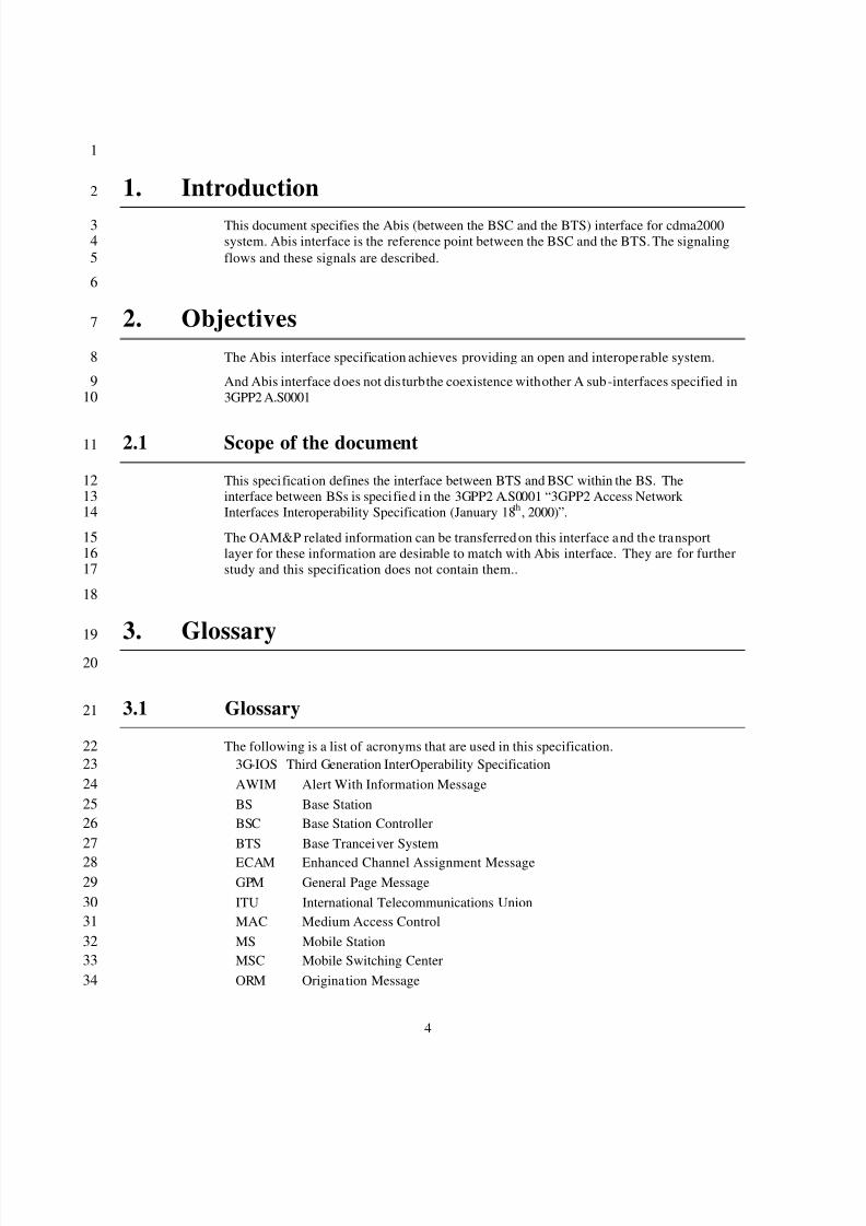
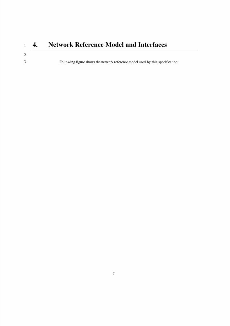
4. Network Reference Model and Interfaces1
2
Following figure shows the network reference model used by this specification.3
8/2/2019 Abis CDMA2000
http://slidepdf.com/reader/full/abis-cdma2000 11/89
8
123
456789
10111213
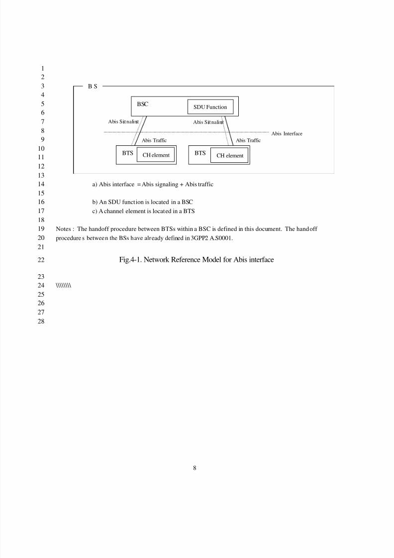
a) Abis interface = Abis signaling + Abis traffic14
15b) An SDU function is located in a BSC16c) A channel element is located in a BTS17
18Notes : The handoff procedure between BTSs within a BSC is defined in this document. The handoff 19procedure s between the BSs have already defined in 3GPP2 A.S0001.20
21
Fig.4-1. Network Reference Model for Abis interface22
23 \\\\\\\\ 24
25262728
Abis Si nalin
Abis Traffic
Abis Si nalin
Abis Traffic
BTS BTS
B S
Abis Interface
BSC SDU Function
CH element CH element
8/2/2019 Abis CDMA2000
http://slidepdf.com/reader/full/abis-cdma2000 12/89
9
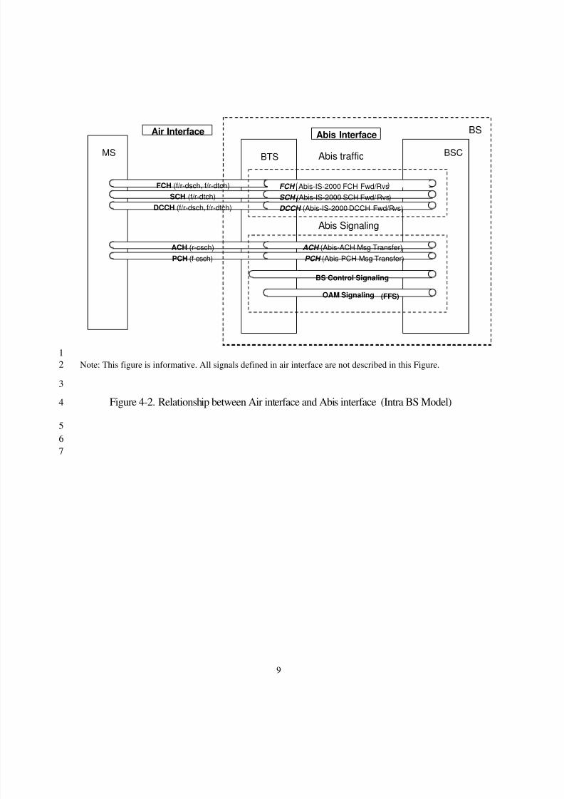
1Note: This figure is informative. All signals defined in air interface are not described in this Figure.2
3
Figure 4-2. Relationship between Air interface and Abis interface (Intra BS Model)4
567
BSCBTS
BS Control Signaling
OAM Signaling
MS
FCH (f/r-dsch, f/r-dtch)SCH (f/r-dtch)
DCCH (f/r-dsch, f/r-dtch)
ACH (r-csch)PCH (f-csch)
Abis Interface
DCCH (Abis-IS-2000 DCCH Fwd/Rvs)
FCH Abis-IS-2000 FCH Fwd/RvsSCH (Abis-IS-2000 SCH Fwd/Rvs)
PCH (Abis-PCH Msg Transfer)ACH (Abis-ACH Msg Transfer)
Air Interface
(FFS)
BS
Abis Signaling
Abis traffic

8/2/2019 Abis CDMA2000
http://slidepdf.com/reader/full/abis-cdma2000 13/89
10
Table 4-1 Abis interface description1Abis function Transaction Abis Message (A7/A3 message related
to Abis )Abis connectionestablish(BSC invoke)
- call setup- Handoff
- Abis -BTS Setup- Abis-BTS Setup Ack - Abis -Connect- Abis -Connect Ack
(A7-HO Req)(A7-HO Req Ack)(A3-Connect)(A3-Connect Ack)
Abis connectionrelease(BSC invoke)
- call release- Handoff
- Abis -BTS Release- Abis-BTS Release Ack - Abis-Remove- Abis-Remove Ack
(A7-Drop)(A7-Drop Ack)(A3-Remove)(A3-Remove Ack)
Abis connectionrelease(BTS invoke)
- Abis -BTS Release Request- Abis -BTS Release- Abis-BTS Release Ack - Abis-Remove- Abis-Remove Ack
(A7-Tgt rm. req.)(A7-Drop)(A7-Drop Ack)(A3-Remove)(A3-Remove Ack)
PCH transfer - Abis-PCH Msg Transfer- Abis -PCH Msg Transfer Ack
(A7-PCH ...)(A7-PCH ... Ack)
ACH transfer - Abis -ACH Msg Transfer- Abis -ACH Msg Transfer Ack
(A7-ACH ...)(A7-ACH ... Ack)
SCH transferand establish
- SCH setup - Abis-Burst Request - Abis-Burst Response-Abis-Burst Commit
(A7-Burst Req.)(A7-Burst Rsp.)(A7-Burst Commit)
23
4.1 Support of user traffic connections to a frame selector function4
In a CDMA system, the user traffic (voice, data, etc.) of a Mobile Station may be connected5
to the network using one or more connections from MS to BTS(s). If multiple connections6are used for a single flow of user information, the user traffic connection is s aid to be in soft7handoff. The first step within the network is to carry these multiple connections back to a8single point from which a selection is made of the “b es t” frame received over the radio9connections. This implies a connection from each involved BTS back to a central point10where frame selection occurs. This central point is referred to as the “SDU function.”11
1213
4.2 Support of paging channel messaging14
When a BS sends a message on a paging channel, the BSC typically formats the majority of 15the message and then forwards it to the BTS along with various parameters including the16destined cell identifier The ability to forward such a paging message from the BSC to t he17BTS is part of the functionality of the Abis interface.18
An additional requirement of a CDMA system is that such messages may also need to be19forwarded between BSCs to be transmitted to a BTS belonging to a BSC other than the20BSC that originally created the message. This requirement comes through support for21access handoff and other such cdmaOne and cdma2000 features. The BSC to BSC22
8/2/2019 Abis CDMA2000
http://slidepdf.com/reader/full/abis-cdma2000 14/89
11
signaling on the A7 interface to suppor t such forwarding has been defined in the 3G-IOS1specification.2
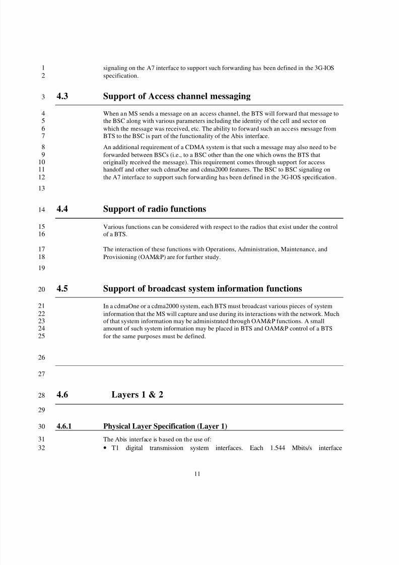
4.3 Support of Access channel messaging3
When an MS sends a message on an access channel, the BTS will forward that message to4the BSC along with various parameters including the identity of the cell and sector on5which the message was received, etc. The ability to forward such an access message from6BTS to the BSC is part of the functionality of the Abis interface.7
An additional requirement of a CDMA system is that such a message may also need to be8forwarded between BSCs (i.e., to a BSC other than the one which owns the BTS that9originally received the message). This requirement comes through support for access10handoff and other such cdmaOne and cdma2000 features. The BSC to BSC signaling on11the A7 interface to support such forwarding has been defined in the 3G-IOS specification .12
13
4.4 Support of radio functions14
Various functions can be considered with respect to the radios that exist under the control15of a BTS.16
The interaction of these functions with Operations, Administration, Maintenance, and17Provisioning (OAM&P) are for further study.18
19
4.5 Support of broadcast system information functions20
In a cdmaOne or a cdma2000 system, each BTS must broadcast various pieces of system21information that the MS will capture and use during its in teractions with the network. Much22of that system information may be administrated through OAM&P functions. A small23amount of such system information may be placed in BTS and OAM&P control of a BTS24for the same purposes must be defined.25
26
27
4.6 Layers 1 & 228
29
4.6.1 Physical Layer Specification (Layer 1)30
The Abis interface is based on the use of:31• T1 digital transmission system interfaces. Each 1.544 Mbits/s interface32
8/2/2019 Abis CDMA2000
http://slidepdf.com/reader/full/abis-cdma2000 15/89
12
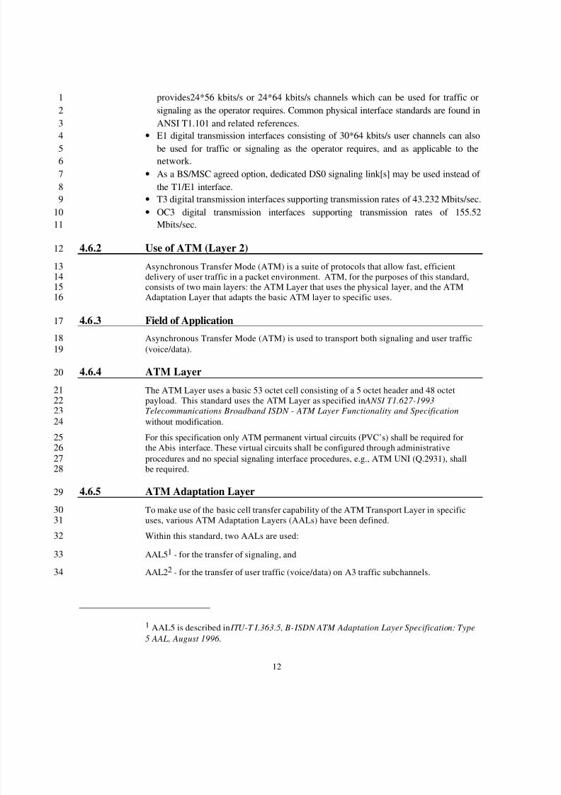
provides24*56 kbits/s or 24*64 kbits/s channels which can be used for traffic or1signaling as the operator requires. Common physical interface standards are found in2ANSI T1.101 and related references.3
•
E1 digital transmission interfaces consisting of 30*64 kbits/s user channels can also4be used for traffic or signaling as the operator requires, and as applicable to the5network. 6
• As a BS/MSC agreed option, dedicated DS0 signaling link[s] may be used instead of 7the T1/E1 interface.8
• T3 digital transmission interfaces supporting transmission rates of 43.232 Mbits/sec.9• OC3 digital transmission interfaces supporting transmission rates of 155.5210
Mbits/sec.11
4.6.2 Use of ATM (Layer 2)12
Asynchronous Transfer Mode (ATM) is a suite of protocols that allow fast, efficient13
delivery of user traffic in a packet environment. ATM, for the purposes of this standard,14 consists of two main layers: the ATM Layer that uses the physical layer, and the ATM15Adaptation Layer that adapts the basic ATM layer to specific uses.16
4.6.3 Field of Application17
Asynchronous Transfer Mode (ATM) is used to transport both signaling and user traffic18(voice/data).19
4.6.4 ATM Layer20
The ATM Layer uses a basic 53 octet cell consisting of a 5 octet header and 48 octet21payload. This standard uses the ATM Layer as specified in ANSI T1.627-199322Telecommunications Broadband ISDN - ATM Layer Functionality and Specification 23without modification.24
For this specification only ATM permanent virtual circuits (PVC’s) shall be required for25the Abis interface. These virtual circuits shall be configured through administrative26procedures and no special signaling interface procedures, e.g., ATM UNI (Q.2931), shall27be required.28
4.6.5 ATM Adaptation Layer29
To make use of the basic cell transfer capability of the ATM Transport Layer in specific30uses, various ATM Adaptation Layers (AALs) have been defined.31
Within this standard, two AALs are used:32
AAL51
- for the transfer of signaling, and33AAL2 2 - for the transfer of user traffic (voice/data) on A3 traffic subchannels.34
1 AAL5 is described in ITU-T I.363.5, B- ISDN ATM Adaptation Layer Specification: Type5 AAL, August 1996 .
8/2/2019 Abis CDMA2000
http://slidepdf.com/reader/full/abis-cdma2000 16/89
13
Both AAL5 and AAL2 will be used without modification in this standard. The Service1Specific Segmentation and Reassembly (SSSAR) sublayer for AAL2, as specified in ITU-T 2
I.366.1 , is used for segmentation and reassembly of AAL2 SDUs.3
In this version of this standard, the functionality of other sublayers of AAL2 is not4supported. Specifically, Service Specific Transmission Error Detection (SSTED) and5Service Specific Assured Data Transfer (SSADT) are not included.6
7
2 AAL2 is described in ITU-T Recommendation I.363.2, B-ISDN ATM Adaptation Layer Type 2 Specification , September 1997.
8/2/2019 Abis CDMA2000
http://slidepdf.com/reader/full/abis-cdma2000 17/89
14
4.6.6 Network and Transport Protocols1
2
4.6.6.1 Signaling Connection Transport Protocol Options3
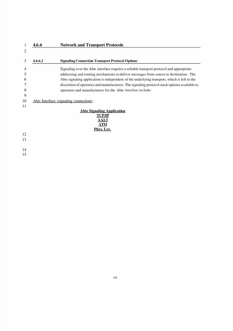
Signaling over the Abis interface requires a reliable transport protocol and appropriate4addressing and routing mechanisms to deliver messages from source to destination. The5Abis signaling application is independent of the underlying transport, which is left to the6discretion of operators and manufacturers. The signaling protocol stack options available to7operators and manufacturers for the Abis interface include:8
9Abis Interface (signaling connection):10
11Abis Signaling Application
TCP/IPAAL5ATM
Phys. Lyr.1213
1415
8/2/2019 Abis CDMA2000
http://slidepdf.com/reader/full/abis-cdma2000 18/89
15
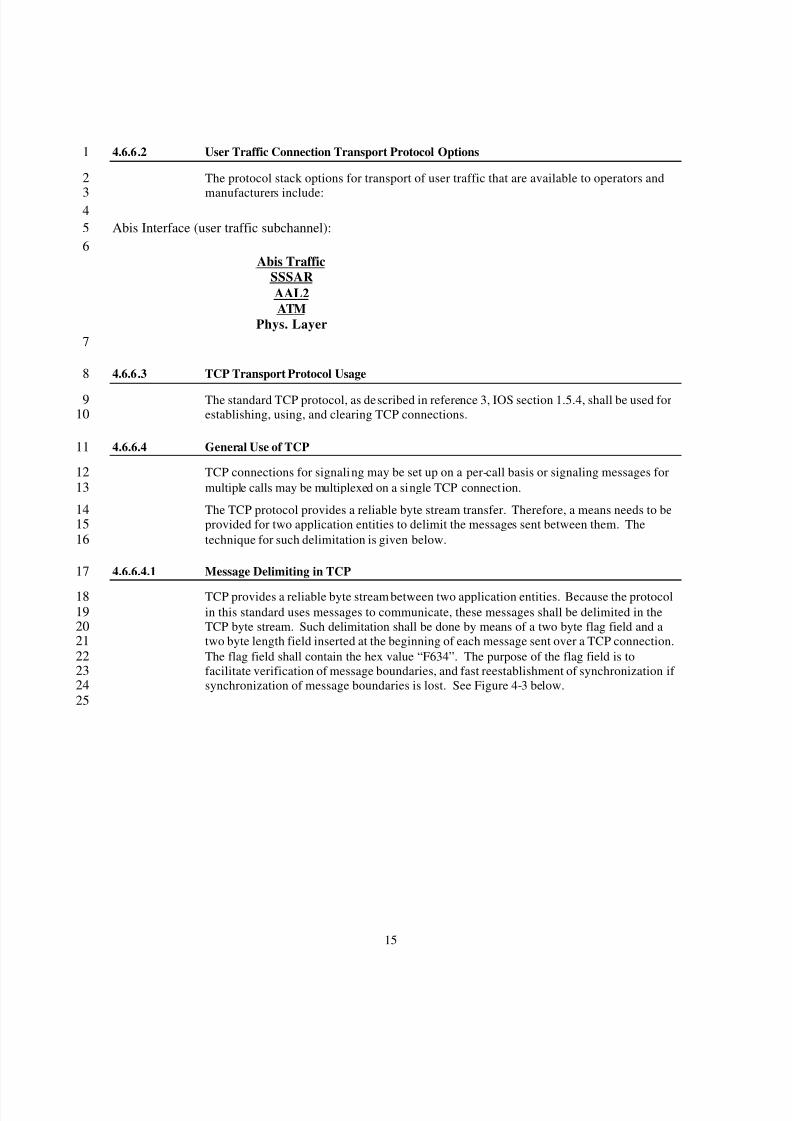
4.6.6.2 User Traffic Connection Transport Protocol Options1
The protocol stack options for transport of user traffic that are available to operators and2
manufacturers include:34
Abis Interface (user traffic subchannel):56
Abis TrafficSSSARAAL2ATM
Phys. Layer7
4.6.6.3 TCP Transport Protocol Usage8
The standard TCP protocol, as described in reference 3, IOS section 1.5.4, shall be used for9establishing, using, and clearing TCP connections.10
4.6.6.4 General Use of TCP11
TCP connections for signaling may be set up on a per-call basis or signaling messages for12multiple calls may be multiplexed on a single TCP connection.13
The TCP protocol provides a reliable byte stream transfer. Therefore, a means needs to be14provided for two application entities to delimit the messages sent between them. The15technique for such delimitation is given below.16
4.6.6.4.1 Message Delimiting in TCP17
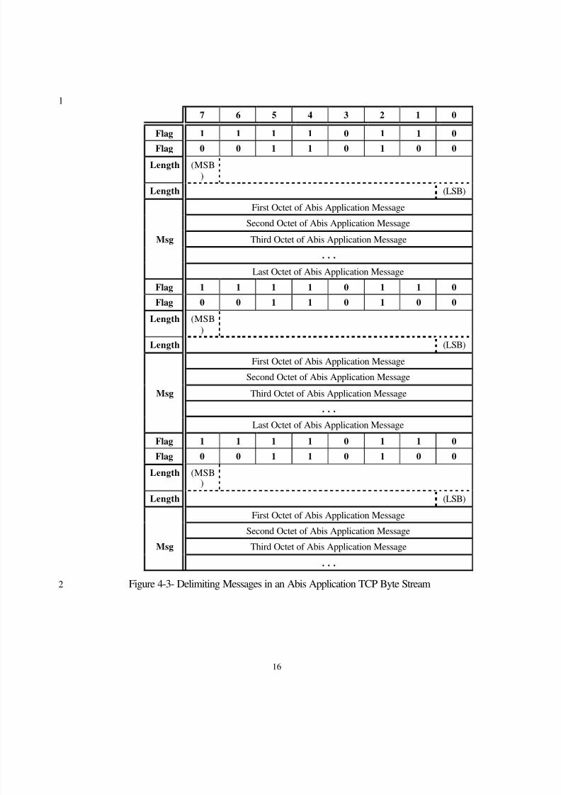
TCP provides a reliable byte stream between two application entities. Because the protocol18in this standard uses messages to communicate, these messages shall be delimited in the19TCP byte stream. Such delimitation shall be done by means of a two byte flag field and a20two byte length field inserted at the beginning of each message sent over a TCP connection.21The flag field shall contain the hex value “F634”. The purpose of the flag field is to22facilitate verification of message boundaries, and fast reestablishment of synchronization if 23synchronization of message boundaries is lost. See Figure 4-3 below.24
25
8/2/2019 Abis CDMA2000
http://slidepdf.com/reader/full/abis-cdma2000 19/89
16
1
7 6 5 4 3 2 1 0
Flag 1 1 1 1 0 1 1 0
Flag 0 0 1 1 0 1 0 0
Length (MSB)
Length (LSB)
First Octet of Abis Application Message
Second Octet of Abis Application Message
Msg Third Octet of Abis Application Message
. . .
Last Octet of Abis Application Message
Flag 1 1 1 1 0 1 1 0
Flag 0 0 1 1 0 1 0 0
Length (MSB)
Length (LSB)
First Octet of Abis Application Message
Second Octet of Abis Application Message
Msg Third Octet of Abis Application Message
. . .
Last Octet of Abis Application Message
Flag 1 1 1 1 0 1 1 0
Flag 0 0 1 1 0 1 0 0
Length (MSB)
Length (LSB)
First Octet of Abis Application Message
Second Octet of Abis Application Message
Msg Third Octet of Abis Application Message
. . .
Figure 4-3- Delimiting Messages in an Abis Application TCP Byte Stream2
8/2/2019 Abis CDMA2000
http://slidepdf.com/reader/full/abis-cdma2000 20/89
17
4.6.6.4.2 TCP Connection Establishment1
A new TCP connection is established when a signaling message re lated to a call has to be2exchanged over an interface, and no such connection exists over the particular interface.3
Normal TCP connection establishment procedures are used.4
4.6.6.4.3 TCP Connection Release5
An existing TCP connection over an interface is released when there are no more signaling6messages to be exchanged over the interface. Normal TCP connection release procedures7are used.8
4.6.6.4.4 TCP Port Usage9
The following TCP port values are reserved for signaling across A bis interfaces:10
Abis: 5604 -- This is the well-known TCP port at a BS used for Abis signaling11interconnection between BTSs and a BSC .12
13
Editor’s Note : These port number is requested now. The value may be changed. And the14value will be defined in A.S0001 later version.15
16
A7: (BS-to-BS) 5602 -- This is the well-known TCP port at a BS used for signaling17interconnection to another BS.18
A9: (BS-to-PCF) 5603 -- This is the well-known TCP/UDP port at a BS used for signaling19interconnection to a PCF.20
4.6.6.5 Use of TCP for the Abis Interface21
The standard " Transport Control Protocol (TCP)", as described in RFC793 and shown in22IOS section 5.4.1 shall be used on the A3 (signaling subchannel) and A7 interfaces.23
4.6.7 IP Network Protocol Usage24
The standard IP protocol, as defined in RFC 791 (see IOS section 1.5.4), shall be used for25routing Internet Protocol packets.26
27

8/2/2019 Abis CDMA2000
http://slidepdf.com/reader/full/abis-cdma2000 21/89
18
1
5. Call Processing2
34
5
67
8
8/2/2019 Abis CDMA2000
http://slidepdf.com/reader/full/abis-cdma2000 22/89
19
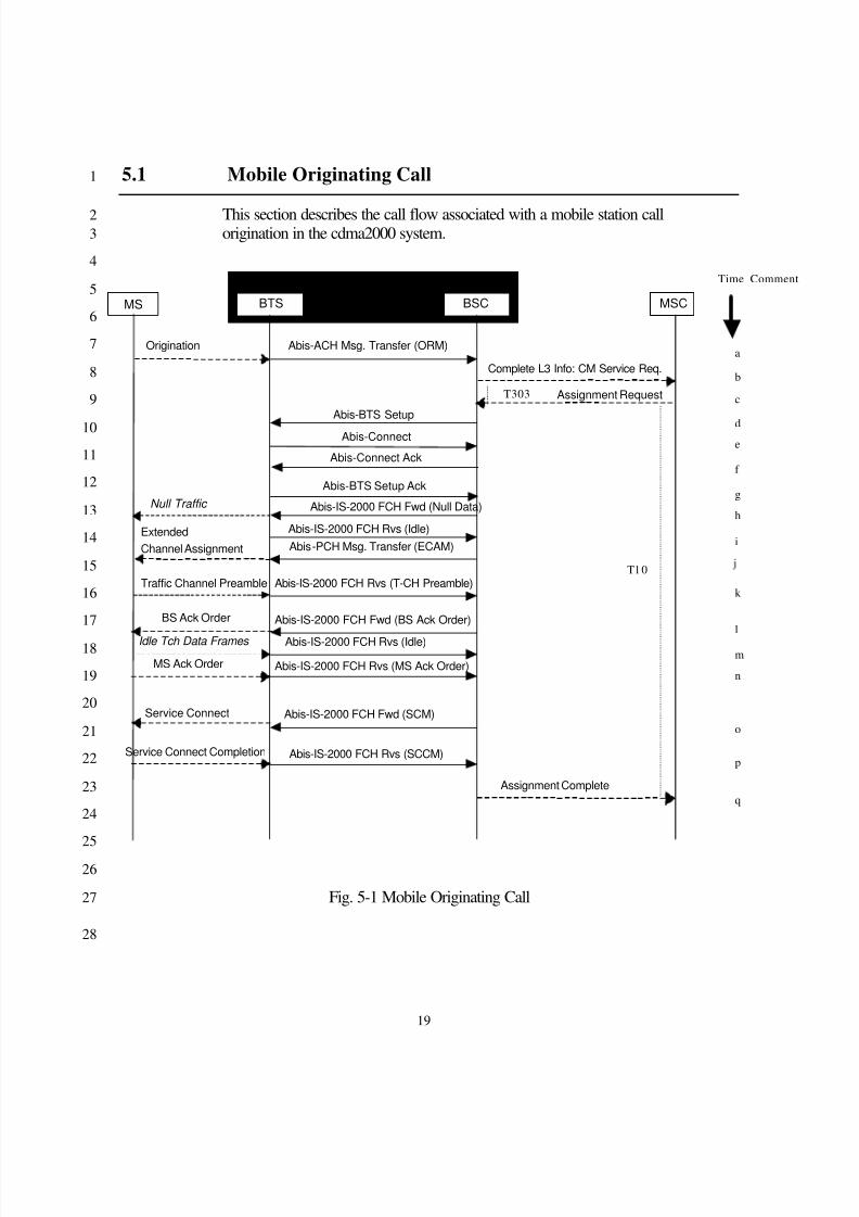
5.1 Mobile Originating Call1
This section describes the call flow associated with a mobile station call2origination in the cdma2000 system.3
4
5
6
7
8
9
10
11
12
13
14
15
16
17
18
19
20
21
22
23
24
25
26
Fig. 5-1 Mobile Originating Call27
28
MS BTS MSC
Origination
Complete L3 Info: CM Service Req.
Assignment Request
ExtendedChannel Assignment
Service Connect
Service Connect Completion
Assignment Complete
BSC BS
Abis-Connect Abis-Connect Ack
Null Traffic Abis-IS-2000 FCH Fwd (Null Data)
Abis-IS-2000 FCH Rvs (Idle)
Traffic Channel Preamble Abis-IS-2000 FCH Rvs (T-CH Preamble)
Abis-IS-2000 FCH Fwd (BS Ack Order) BS Ack Order
Idle Tch Data Frames Abis-IS-2000 FCH Rvs (Idle) MS Ack Order Abis-IS-2000 FCH Rvs (MS Ack Order)
Abis-IS-2000 FCH Fwd (SCM)
Abis-IS-2000 FCH Rvs (SCCM)
Abis-BTS Setup
Abis-ACH Msg. Transfer (ORM)
Abis-PCH Msg. Transfer (ECAM)
a
b
c
de
f
g
i
k
l
m
n
o
p
q
T303
T10
Time Comment
Abis-BTS Setup Ack
h
8/2/2019 Abis CDMA2000
http://slidepdf.com/reader/full/abis-cdma2000 23/89
20
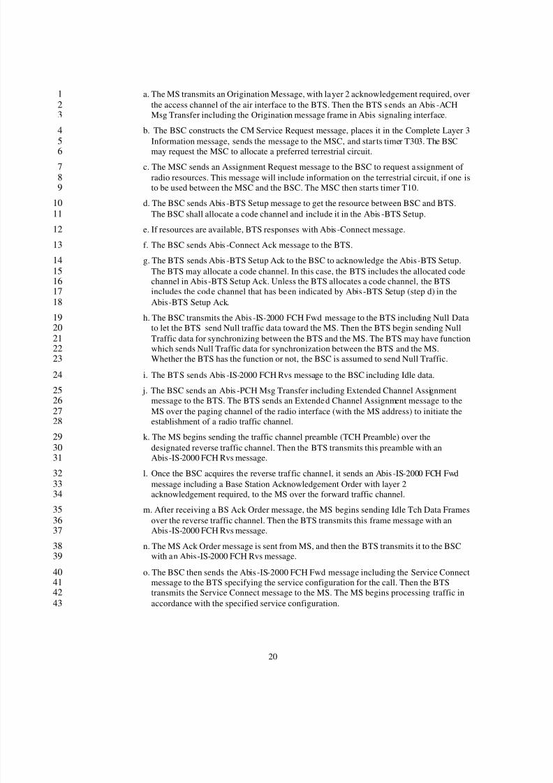
a. The MS transmits an Origination Message, with layer 2 acknowledgement required, over1the access channel of the air interface to the BTS. Then the BTS sends an Abis -ACH2Msg Transfer including the Origination message frame in Abis signaling interface.3
b. The BSC constructs the CM Service Request message, places it in the Complete Layer 34Information message, sends the message to the MSC, and star ts timer T303. The BSC5may request the MSC to allocate a preferred terrestrial circuit.6
c. The MSC sends an Assignment Request message to the BSC to request assignment of 7radio resources. This message will include information on the terrestrial circuit, if one is8to be used between the MSC and the BSC. The MSC then starts timer T10.9
d. The BSC sends Abis -BTS Setup message to get the resource between BSC and BTS.10The BSC shall allocate a code channel and include it in the Abis -BTS Setup.11
e. If resources are available, BTS responses with Abis -Connect message.12
f. The BSC sends Abis -Connect Ack message to the BTS.13
g. The BTS sends Abis -BTS Setup Ack to the BSC to acknowledge the Abis-BTS Setup.14
The BTS may allocate a code channel. In this case, the BTS includes the allocated code15 channel in Abis-BTS Setup Ack. Unless the BTS allocates a code channel, the BTS16includes the code channel that has been indicated by Abis -BTS Setup (step d) in the17Abis-BTS Setup Ack.18
h. The BSC transmits the Abis -IS-2000 FCH Fwd message to the BTS including Null Data19to let the BTS send Null traffic data toward the MS. Then the BTS begin sending Null20Traffic data for synchronizing between the BTS and the MS. The BTS may have function21which sends Null Traffic data for synchronization between the BTS and the MS.22Whether the BTS has the function or not, the BSC is assumed to send Null Traffic.23
i. The BTS sends Abis -IS-2000 FCH Rvs message to the BSC including Idle data.24
j. The BSC sends an Abis -PCH Msg Transfer including Extended Channel Assignment25message to the BTS. The BTS sends an Extended Channel Assignment message to the26
MS over the paging channel of the radio interface (with the MS address) to initiate the27establishment of a radio traffic channel.28
k. The MS begins sending the traffic channel preamble (TCH Preamble) over the29designated reverse traffic channel. Then the BTS transmits this preamble with an30Abis-IS-2000 FCH Rvs message.31
l. Once the BSC acquires the reverse traffic channel, it sends an Abis -IS-2000 FCH Fwd32message including a Base Station Acknowledgement Order with layer 233acknowledgement required, to the MS over the forward traffic channel.34
m. After receiving a BS Ack Order message, the MS begins sending Idle Tch Data Frames35over the reverse traffic channel. Then the BTS transmits this frame message with an36Abis-IS-2000 FCH Rvs message.37
n. The MS Ack Order message is sent from MS, and then the BTS transmits it to the BSC38 with an Abis-IS-2000 FCH Rvs message.39
o. The BSC then sends the Abis -IS-2000 FCH Fwd message including the Service Connect40message to the BTS specifying the service configuration for the call. Then the BTS41transmits the Service Connect message to the MS. The MS begins processing traffic in42accordance with the specified service configuration.43
8/2/2019 Abis CDMA2000
http://slidepdf.com/reader/full/abis-cdma2000 24/89
21
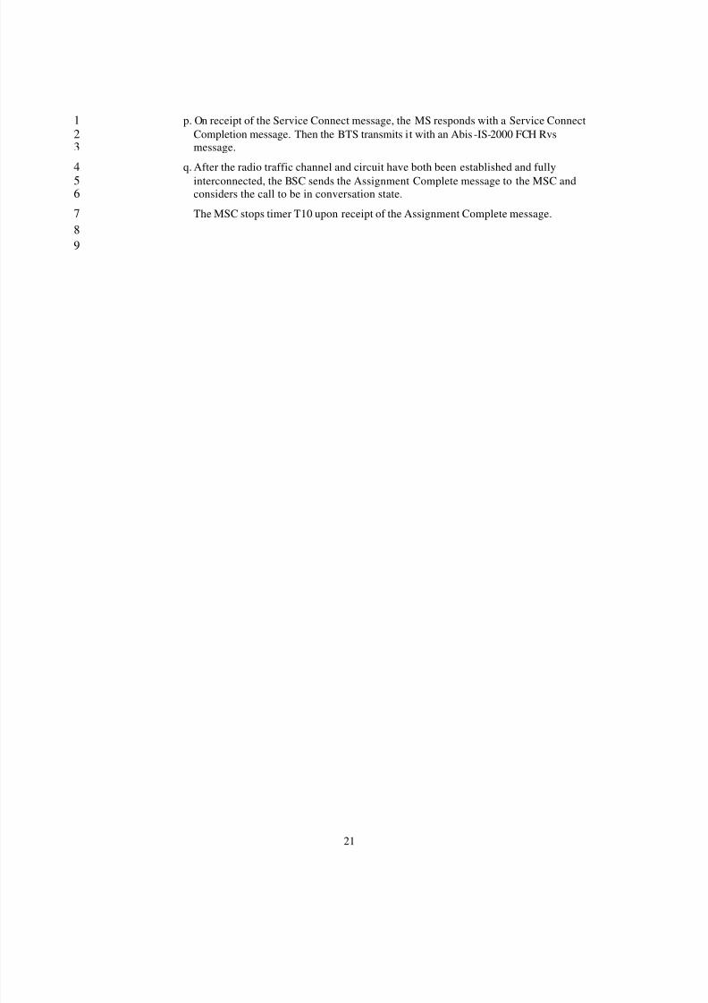
p. On receipt of the Service Connect message, the MS responds with a Service Connect1Completion message. Then the BTS transmits i t with an Abis -IS-2000 FCH Rvs2message.3
q. After the radio traffic channel and circuit have both been established and fully4interconnected, the BSC sends the Assignment Complete message to the MSC and5considers the call to be in conversation state.6
The MSC stops timer T10 upon receipt of the Assignment Complete message.789
8/2/2019 Abis CDMA2000
http://slidepdf.com/reader/full/abis-cdma2000 25/89
22
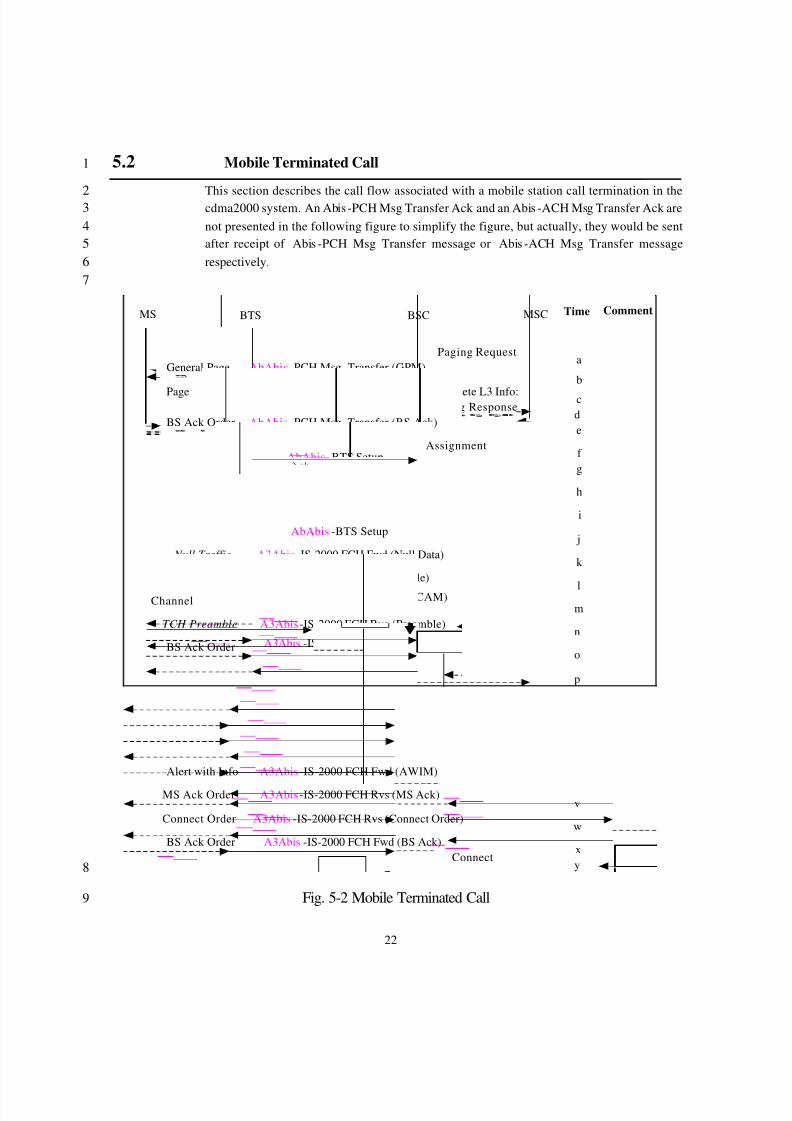
5.2 Mobile Terminated Call 1
This section describes the call flow associated with a mobile station call termination in the2 cdma2000 system. An Abis -PCH Msg Transfer Ack and an Abis -ACH Msg Transfer Ack are3not presented in the following figure to simplify the figure, but actually, they would be sent4after receipt of Abis -PCH Msg Transfer message or Abis -ACH Msg Transfer message5respectively.6
7
MS BTS MSC Time Comment
a
b
cde
f g
Paging Request
BSC
h
k
i
lm
n
o
AbAbis -PCH Msg. Transfer (GPM)General Page
Complete L3 Info:Paging Response
p
q
r
stu
Page AbAbis -ACH Msg. Transfer
AbAbis -PCH Msg. Transfer (BS Ack)BS Ack Order
AssignmentAbAbis -BTS Setup
A3Abis -Connect
A3Abis -Connect Ack
A3Abis -IS-2000 FCH Fwd (Null Data) Null Traffic
A3Abis -IS-2000 FCH Rvs (Idle)
AbAbis -PCH Msg. Transfer (ECAM)ExtendedChannel
TCH Preamble A3Abis -IS-2000 FCH Rvs (Preamble)
A3Abis -IS-2000 FCH Fwd (BS Ack)BS Ack Order
Idle Tch Data A3Abis -IS-2000 FCH Rvs (Idle)
MS Ack A3Abis -IS-2000 FCH Rvs (MS Ack)
A3Abis -IS-2000 FCH Fwd (SCM)Service Connect
Serv. Con. Completion A3Abis -IS-2000 FCH Rvs (SCCM)Assignment
A3Abis -IS-2000 FCH Fwd (AWIM)Alert with Info
MS Ack Order A3Abis -IS-2000 FCH Rvs (MS Ack)
Connect Order A3Abis -IS-2000 FCH Rvs (Connect Order)
A3Abis -IS-2000 FCH Fwd (BS Ack)BS Ack OrderConnect
v
w
xy
jAbAbis -BTS Setup
8
Fig. 5-2 Mobile Terminated Call9

8/2/2019 Abis CDMA2000
http://slidepdf.com/reader/full/abis-cdma2000 26/89
23
1
8/2/2019 Abis CDMA2000
http://slidepdf.com/reader/full/abis-cdma2000 27/89
24
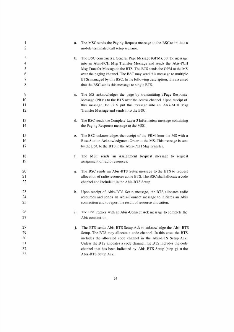
a. The MSC sends the Paging Request message to the BSC to initiate a1mobile terminated call setup scenario.2
b. The BSC constructs a General Page Message (GPM), put the message3into an Abis-PCH Msg Transfer Message and sends the Abis-PCH4Msg Transfer Message to the BTS. The BTS sends the GPM to the MS5over the paging channel. The BSC may send this message to multiple6BTSs managed by this BSC. In the following description, it is assumed7that the BSC sends this message to single BTS.8
c. The MS acknowledges the page by transmitting a Page Response9Message (PRM) to the BTS over the access channel. Upon receipt of 10this message, the BTS put this message into an Abis-ACH Msg11Transfer Message and sends it to the BSC.12
d. The BSC sends the Complete Layer 3 Information message containing13the Paging Response message to the MSC.14
e. The BSC acknowledges the receipt of the PRM from the MS with a15Base Station Acknowledgment Order to the MS. This message is sent16by the BSC to the BTS in the Abis-PCH Msg Transfer.17
f. The MSC sends an Assignment Request message to request18assignment of radio resources.19
g. The BSC sends an Abis-BTS Setup message to the BTS to request20allocation of radio resources at the BTS. The BSC shall allocate a code21channel and include it in the Abis-BTS Setup.22
h. Upon receipt of Abis-BTS Setup message, the BTS allocates radio23resources and sends an Abis -Connect message to initiates an Abis24connection and to report the result of resource allocation.25
i. The BSC replies with an Abis-Connect Ack message to complete the26Abis connect ion.27
j. The BTS sends Abis -BTS Setup Ack to acknowledge the Abis -BTS28
Setup. The BTS may allocate a code channel. In this case, the BTS29includes the allocated code channel in the Abis-BTS Setup Ack.30Unless the BTS allocates a code channel, the BTS includes the code31channel that has been indicated by Abis -BTS Setup (step g) in the32Abis-BTS Setup Ack.33

8/2/2019 Abis CDMA2000
http://slidepdf.com/reader/full/abis-cdma2000 28/89
25
k. The BSC sends an Abis -IS-2000 FCH Fwd (Null Traffic Data)1message to the BTS. The BTS starts sending Null Traffic Data to the2MS. This allows the MS to acquire the FCH (Fundamental channel).3
The BTS may have function which sends Null Traffic data for4 synchronization between the BTS and the MS. Whether the BTS has5the function or not, the BSC is assumed to send Null Traffic. 6
l. Upon receiving the first Abis -IS-2000 FCH Fwd (Null Traffic Data)7message, the BTS starts to send Abis-IS-2000 FCH Rvs (Idle frame)8message to the BSC.9
m. The BSC sends an Extended Channel Assignment message to assign10the FCH.11
n. The MS starts to send the Traffic Channel Preamble. Upon receiving12the Traffic Channel Preamble, the BTS stops sending the idle frames13and starts sending the traffic frames containing the Traffic Channel14Preamble.15
o. The BSC sends the BS Ack Order to the MS via the BTS in the16Abis -IS-2000 FCH Fwd message.17
p. The MS stops transmitting the Traffic Channel Preamble and starts to18transmit idle traffic channel data frames upon receipt of the BS Ack 19order.20
q. The MS sends the MS Ack Order to acknowledge the BS Ack order.21This is sent by the BTS to the BSC in the Abis -IS-2000 FCH Rvs22message.23
r. The BSC sends the Service Connect Message (SCM) to the MS24specifying the service configuration for the call. This message is sent25by the BSC to the BTS in the Abis-IS-2000 FCH Fwd message. The26MS begins processing traffic in accordance with the specified service27configuration.28
s. On receipt of the Service Connect Message (SCM), the MS responds29
with a Service Connect Completion Message (SCCM). Upon receipt30 of this message at the BTS, it sends Abis -IS-2000 FCH Rvs message31containing this message to the BSC.32
t. After the radio traffic channel and circuit have both been established,33the BSC sends the Assignment Complete message to the MSC.34
8/2/2019 Abis CDMA2000
http://slidepdf.com/reader/full/abis-cdma2000 29/89
26
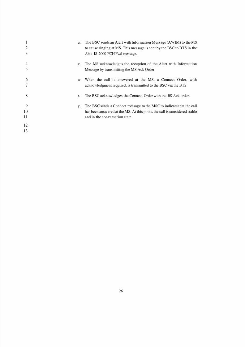
u. The BSC sends an Alert with Information Message (AWIM) to the MS1to cause ringing at MS. This message is sent by the BSC to BTS in the2Abis -IS-2000 FCH Fwd message.3
v. The MS acknowledges the reception of the Alert with Information4Message by transmitting the MS Ack Order.5
w. When the call is answered at the MS, a Connect Order, with6acknowledgment required, is transmitted to the BSC via the BTS.7
x. The BSC acknowledges the Connect Order with the BS Ack order.8
y. The BSC sends a Connect message to the MSC to indicate that the call9has been answered at the MS. At this point, the call is considered stable10and in the conversation state.11
1213
8/2/2019 Abis CDMA2000
http://slidepdf.com/reader/full/abis-cdma2000 30/89
27
5.3 Call Clearing1
2
5.3.1 Call Clearing initiated by MS3
4
56789
10
11121314151617181920
21
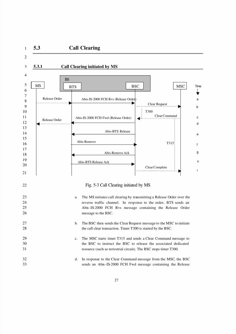
Fig. 5-3 Call Clearing initiated by MS22
a. The MS initiates call clearing by transmitting a Release Order over the23reverse traffic channel. In response to the order, BTS sends an24Abis -IS-2000 FCH Rvs message containing the Release Order25message to the BSC.26
b. The BSC then sends the Clear Request message to the MSC to initiate27the call clear transaction. Timer T300 is started by the BSC.28
c. The MSC starts timer T315 and sends a Clear Command message to29the BSC to instruct the BSC to release the associated dedicated30resource (such as terrestrial circuit). The BSC stops timer T300.31
d. In response to the Clear Command message from the MSC, the BSC32sends an Abis -IS-2000 FCH Fwd message containing the Release33
MS BTS MSC
Clear Request
Clear Command
Clear Complete
BSC
BS
Release Order Abis-IS-2000 FCH Rvs (Release Order)
Abis-IS-2000 FCH Fwd (Release Order)Release Order
Abis-Remove
Abis-Remove Ack
T300
T315
a
b
c
d
e
f
g
Time
Abis-BTS Release
Abis-BTS Release Ack
i
h
8/2/2019 Abis CDMA2000
http://slidepdf.com/reader/full/abis-cdma2000 31/89
28
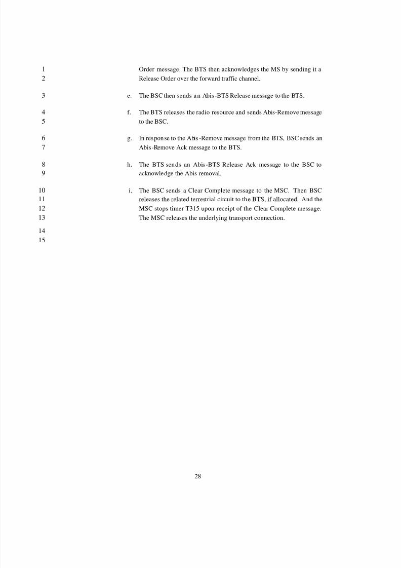
Order message. The BTS then acknowledges the MS by sending it a1Release Order over the forward traffic channel.2
e. The BSC then sends an Abis-BTS Release message to the BTS.3
f. The BTS releases the radio resource and sends Abis-Remove message4to the BSC.5
g. In response to the Abis -Remove message from the BTS, BSC sends an6Abis-Remove Ack message to the BTS.7
h. The BTS sends an Abis -BTS Release Ack message to the BSC to8acknowledge the Abis removal.9
i. The BSC sends a Clear Complete message to the MSC. Then BSC10
releases the related terrestrial circuit to the BTS, if allocated. And the11MSC stops timer T315 upon receipt of the Clear Complete message.12The MSC releases the underlying transport connection.13
1415

8/2/2019 Abis CDMA2000
http://slidepdf.com/reader/full/abis-cdma2000 32/89
29
5.3.2 Call Clearing initiated by BS/MSC1
2
3
4
5
67
8
9
10
11
Fig. 5-4 Call Clearing initiated by BS/MSC12
a. In the case where the BSC detects some failures related the call, the13BSC sends a Clear Request message to the MSC. The BSC starts timer14T300 and waits for the Clear Command from the MSC (step b). A Call15Clearing flow initiated by BSC starts from this step.16
b. The MSC starts timer T315 and sends a Clear Command message to17instruct the BSC to release the associated dedicated resource (such as18terrestrial circuit). In the case of a Call Clearing initiated BS, the BSC19stops timer T300. A Call Clearing flow initiated by MSC starts from20this step.21
c. In response to the Clear Command message from the MSC, the BSC22sends Abis-IS-2000 FCH Fwd containing the Release Order message.23The BTS sends the Release Order message to the MS over the forward24traffic channel.25
d. The MS replies with a Release Order over the reverse traffic channel.26In response to the order, BTS sends an Abis -IS-2000 FCH Reverse27containing the Release Order message to the BSC.28
MS BTS MSC
Clear Request
Clear Command
BSC
BS
Release Order Abis-IS-2000 FCH Fwd (Release Order)
Abis-IS-2000 FCH Rvs (Release Order)Release Order
Abis-Remove
Abis-Remove Ack
T300
T315
a
b
c
d
e
f
g
Time
Abis-BTS Release
i
Abis-BTS Release Ack
MS BTS MSC
Clear Request
Clear Command
Clear Complete
BSC
BS
Release Order
Release Order
T300
T315
a
b
c
d
e
f
g
Time
h
8/2/2019 Abis CDMA2000
http://slidepdf.com/reader/full/abis-cdma2000 33/89
30
e. The BSC then sends an Abis-BTS Release message to the BTS.1
f. The BTS releases the radio resource and sends Abis Remove message2to the BSC.3
g. In response to the Abis Remove message from the BTS and BSC sends4an Abis Remove Ack message to the BTS. Then BSC releases the5related terrestrial circuit to the BTS, if allocated.6
h. The BS sends an Abis -BTS Release Ack message to the BSC to7acknowledge the Abis removal8
i. Upon receipt of the Abis BTS Release Ack message, the BSC sends9the Clear Complete message to the MSC. The MSC stops timer T31510upon receipt of the Clear Complete message. The MSC releases the11underlying transport connection.12
5.3.3 Call Clearing initiated by BTS13
14
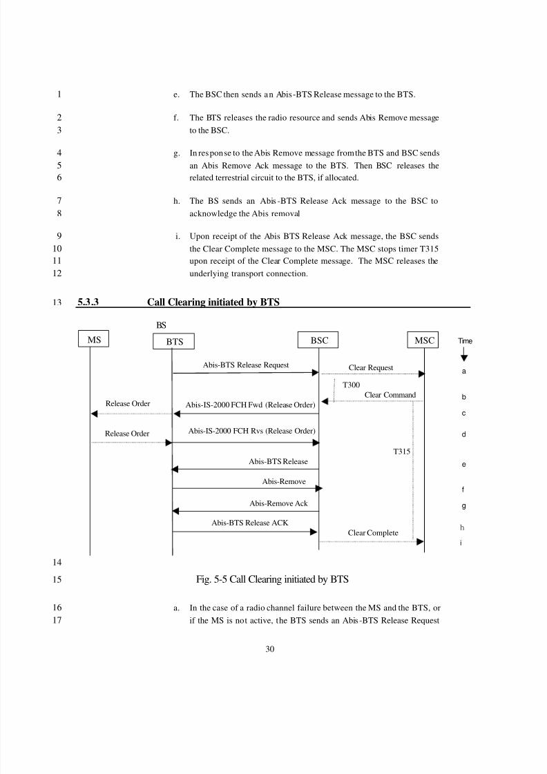
Fig. 5-5 Call Clearing initiated by BTS15
a. In the case of a radio channel failure between the MS and the BTS, or16if the MS is not active, the BTS sends an Abis -BTS Release Request17
MS BTS MSC
Clear Request
Clear Command
Clear Complete
BSC
BS
Release Order Abis-IS-2000 FCH Fwd (Release Order)
Abis-IS-2000 FCH Rvs (Release Order)Release Order
Abis-Remove
Abis-Remove Ack
T300
T315
a
b
c
d
e
f
g
Time
Abis-BTS Release
i
Abis-BTS Release Request
Abis-BTS Release ACK h
8/2/2019 Abis CDMA2000
http://slidepdf.com/reader/full/abis-cdma2000 34/89
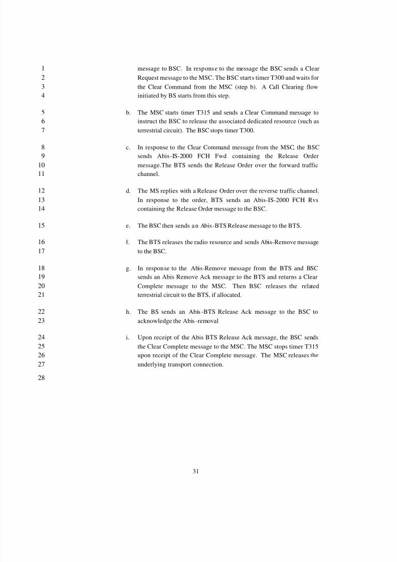
31
message to BSC. In response to the message the BSC sends a Clear1Request message to the MSC. The BSC starts timer T300 and waits for2the Clear Command from the MSC (step b). A Call Clearing flow3
initiated by BS starts from this step.4
b. The MSC starts timer T315 and sends a Clear Command message to5instruct the BSC to release the associated dedicated resource (such as6terrestrial circuit). The BSC stops timer T300.7
c. In response to the Clear Command message from the MSC, the BSC8sends Abis -IS-2000 FCH Fwd containing the Release Order9message.The BTS sends the Release Order over the forward traffic10channel.11
d. The MS replies with a Release Order over the reverse traffic channel.12In response to the order, BTS sends an Abis-IS-2000 FCH Rvs13containing the Release Order message to the BSC.14
e. The BSC then sends an Abis-BTS Release message to the BTS.15
f. The BTS releases the radio resource and sends Abis-Remove message16to the BSC.17
g. In response to the Abis-Remove message from the BTS and BSC18sends an Abis Remove Ack message to the BTS and returns a Clear19Complete message to the MSC. Then BSC releases the related20
terrestrial circuit to the BTS, if allocated.21
h. The BS sends an Abis -BTS Release Ack message to the BSC to22acknowledge the Abis -removal23
i. Upon receipt of the Abis BTS Release Ack message, the BSC sends24the Clear Complete message to the MSC. The MSC stops timer T31525upon receipt of the Clear Complete message. The MSC releases the26underlying transport connection.27
28
8/2/2019 Abis CDMA2000
http://slidepdf.com/reader/full/abis-cdma2000 35/89
32
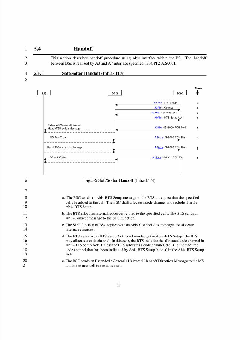
5.4 Handoff 1
This section describes handoff procedure using Abis interface within the BS. The handoff 2 between BSs is realized by A3 and A7 interface specified in 3GPP2 A.S0001.3
5.4.1 Soft/Softer Handoff (Intra-BTS)45
Fig.5-6 Soft/Softer Handoff (Intra-BTS)6
7
a. The BSC sends an Abis-BTS Setup message to the BTS to request that the specified8cells be added to the call. The BSC shall allocate a code channel and include it in the9Abis -BTS Setup.10
b. The BTS allocates internal resources related to the specified cells. The BTS sends an11Abis -Connect message to the SDU function.12
c. The SDU function of BSC replies with an Abis-Connect Ack message and allocate13internal resources .14
d. The BTS sends Abis -BTS Setup Ack to acknowledge the Abis -BTS Setup. The BTS15 may allocate a code channel. In this case, the BTS includes the allocated code channel in16
Abis -BTS Setup Ack. Unless the BTS allocates a code channel, the BTS includes the17code channel that has been indicated by Abis-BTS Setup (step a) in the Abis -BTS Setup18Ack.19
e. The BSC sends an Extended / General / Universal Handoff Direction Message to the MS20to add the new cell to the active set .21
Ab Abis -BTS Setup
MS BSC
Extended/General/UniversalHandoff Direction Message
MS Ack Order
Handoff Completion Message
BS Ack Order
aA3Abis -Connect
A3Abis -Connect Ack
AbAbis -BTS Setup Ack
Time
b
c
d
e
f
g
h
A3Abis -IS-2000 FCH Fwd
A3Abis -IS-2000 FCH Rvs
A3Abis -IS-2000 FCH Rvs
A3Abis -IS-2000 FCH Fwd
BT S
8/2/2019 Abis CDMA2000
http://slidepdf.com/reader/full/abis-cdma2000 36/89
33
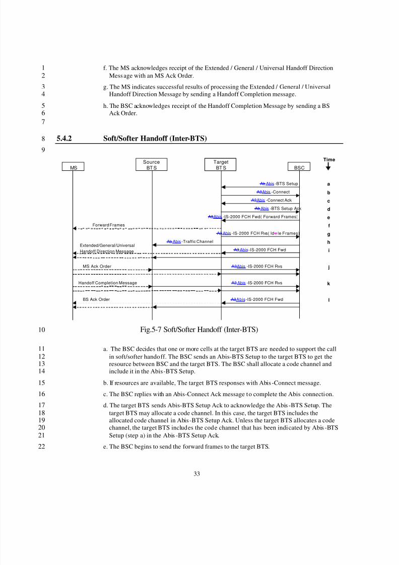
f. The MS acknowledges receipt of the Extended / General / Universal Handoff Direction1Message with an MS Ack Order.2
g. The MS indicates successful results of processing the Extended / General / Universal3Handoff Direction Message by sending a Handoff Completion message.4
h. The BSC acknowledges receipt of the Handoff Completion Message by sending a BS5Ack Order.6
7
5.4.2 Soft/Softer Handoff (Inter-BTS)8
9
Fig.5-7 Soft/Softer Handoff (Inter-BTS)10
a. The BSC decides that one or more cells at the target BTS are needed to support the call11in soft/softer handoff. The BSC sends an Abis-BTS Setup to the target BTS to get the12resource between BSC and the target BTS. The BSC shall allocate a code channel and13include it in the Abis-BTS Setup.14
b. If resources are available, The target BTS responses with Abis -Connect message.15
c. The BSC replies with an Abis-Connect Ack message to complete the Abis connection.16d. The target BTS sends Abis-BTS Setup Ack to acknowledge the Abis -BTS Setup. The17
target BTS may allocate a code channel. In this case, the target BTS includes the18allocated code channel in Abis -BTS Setup Ack. Unless the target BTS allocates a code19channel, the target BTS includes the code channel that has been indicated by Abis -BTS20Setup (step a) in the Abis -BTS Setup Ack.21
e. The BSC begins to send the forward frames to the target BTS.22
Ab Abis -BTS Setup
MS BSCSource
BT S
Extended/General/UniversalHandoff Direction Message
MS Ack Order
Handoff Completion Message
Ab Abis -Traffic Channel
BS Ack Order
a
A3Abis -Connect
A3Abis -Connect Ack
A3Abis -IS-2000 FCH Fwd( Forward Frames)
A3 Abis -IS-2000 FCH Rvs( Id e le Frames)
Forward Frames
Ab Abis -BTS Setup Ack
TargetBT S
Time
b
c
d
e
f
g
h
j
i
k
l
A3 Abis -IS-2000 FCH Fwd
A3Abis -IS-2000 FCH Rvs
A3 Abis -IS-2000 FCH Rvs
A3Abis -IS-2000 FCH Fwd
8/2/2019 Abis CDMA2000
http://slidepdf.com/reader/full/abis-cdma2000 37/89
34
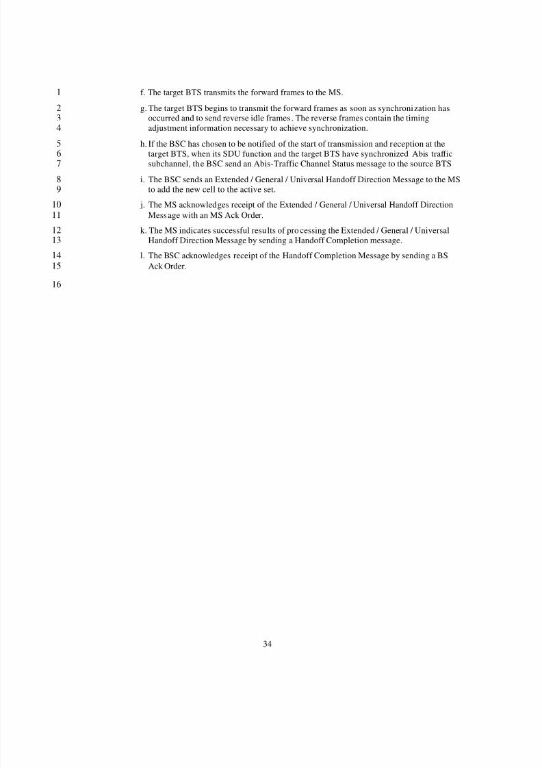
f. The target BTS transmits the forward frames to the MS.1
g. The target BTS begins to transmit the forward frames as soon as synchronization has2occurred and to send reverse idle frames . The reverse frames contain the timing3adjustment information necessary to achieve synchronization.4
h. If the BSC has chosen to be notified of the start of transmission and reception at the5target BTS, when its SDU function and the target BTS have synchronized Abis traffic6subchannel, the BSC send an Abis-Traffic Channel Status message to the source BTS7
i. The BSC sends an Extended / General / Universal Handoff Direction Message to the MS8to add the new cell to the active set.9
j. The MS acknowledges receipt of the Extended / General / Universal Handoff Direction10Message with an MS Ack Order.11
k. The MS indicates successful results of pro cessing the Extended / General / Universal12Handoff Direction Message by sending a Handoff Completion message.13
l. The BSC acknowledges receipt of the Handoff Completion Message by sending a BS14
Ack Order.1516
8/2/2019 Abis CDMA2000
http://slidepdf.com/reader/full/abis-cdma2000 38/89
35
5.5 SMS Delivery1
2
5.5.1 SMS Delivery on the Paging channel3
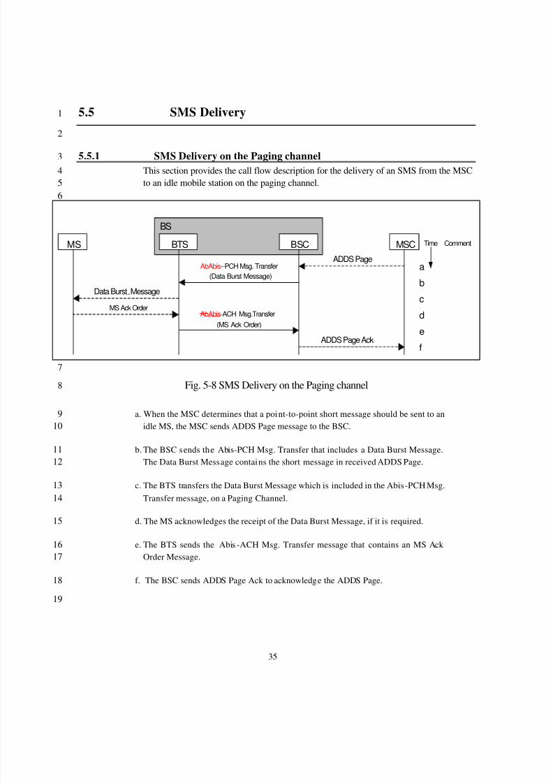
This section provides the call flow description for the delivery of an SMS from the MSC4to an idle mobile station on the paging channel.5
6
7
Fig. 5-8 SMS Delivery on the Paging channel8
a. When the MSC determines that a point-to-point short message should be sent to an9idle MS, the MSC sends ADDS Page message to the BSC.10
b. The BSC sends the Abis-PCH Msg. Transfer that includes a Data Burst Message.11The Data Burst Message contains the short message in received ADDS Page.12
c. The BTS transfers the Data Burst Message which is included in the Abis -PCH Msg.13Transfer message, on a Paging Channel.14
d. The MS acknowledges the receipt of the Data Burst Message, if it is required.15
e. The BTS sends the Abis -ACH Msg. Transfer message that contains an MS Ack 16 Order Message.17
f. The BSC sends ADDS Page Ack to acknowledge the ADDS Page.18
19
MS BTS MSCADDS Page
ADDS Page Ack
BSC
BS
MS Ack Order
Data Burst Message
AbAbis --PCH Msg. Transfer
(Data Burst Message)
AbAbis -ACH Msg.Transfer(MS Ack Order)
a
b
c
d
e
f
Time Comment
8/2/2019 Abis CDMA2000
http://slidepdf.com/reader/full/abis-cdma2000 39/89
36
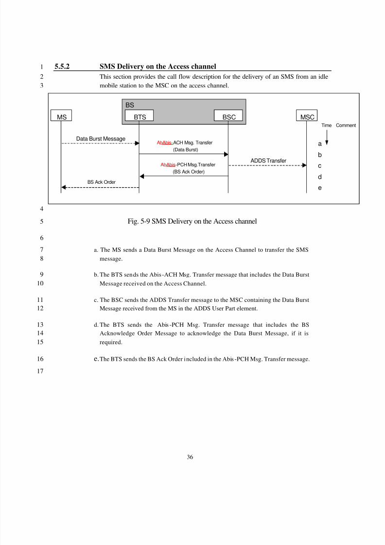
5.5.2 SMS Delivery on the Access channel1
This section provides the call flow description for the delivery of an SMS from an idle2mobile station to the MSC on the access channel.3
4
Fig. 5-9 SMS Delivery on the Access channel5
6
a. The MS sends a Data Burst Message on the Access Channel to transfer the SMS7message.8
b. The BTS sends the Abis -ACH Msg. Transfer message that includes the Data Burst9
Message received on the Access Channel.10
c. The BSC sends the ADDS Transfer message to the MSC containing the Data Burst11Message received from the MS in the ADDS User Part element.12
d. The BTS sends the Abis -PCH Msg. Transfer message that includes the BS13Acknowledge Order Message to acknowledge the Data Burst Message, if it is14required.15
e. The BTS sends the BS Ack Order included in the Abis -PCH Msg. Transfer message. 16
17
MS BTS MSC
ADDS Transfer
BSC
BS
BS Ack Order
Data Burst MessageAbAbis -ACH Msg. Transfer
(Data Burst)
AbAbis -PCH Msg.Transfer(BS Ack Order)
a
b
c
d
e
Time Comment
8/2/2019 Abis CDMA2000
http://slidepdf.com/reader/full/abis-cdma2000 40/89
37
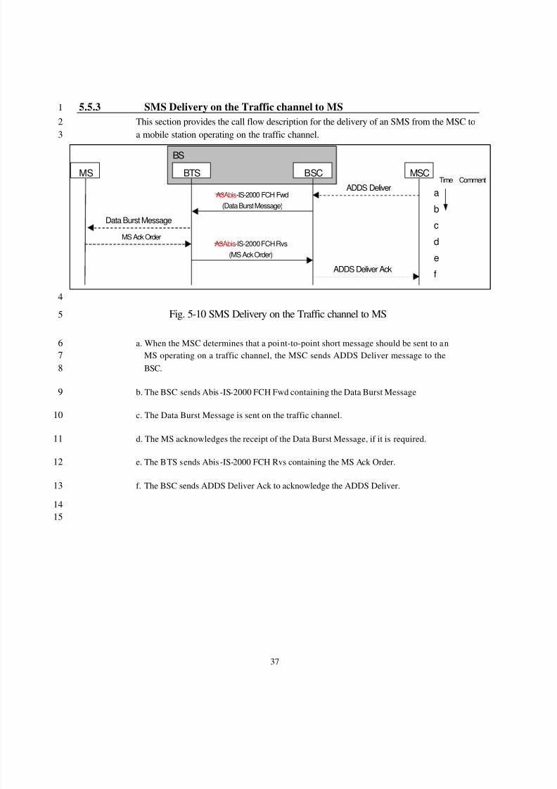
5.5.3 SMS Delivery on the Traffic channel to MS1
This section provides the call flow description for the delivery of an SMS from the MSC to2
a mobile station operating on the traffic channel.3
4
Fig. 5-10 SMS Delivery on the Traffic channel to MS5
a. When the MSC determines that a point-to-point short message should be sent to an6MS operating on a traffic channel, the MSC sends ADDS Deliver message to the7BSC.8
b. The BSC sends Abis -IS-2000 FCH Fwd containing the Data Burst Message9
c. The Data Burst Message is sent on the traffic channel.10
d. The MS acknowledges the receipt of the Data Burst Message, if it is required.11
e. The BTS sends Abis -IS-2000 FCH Rvs containing the MS Ack Order.12
f. The BSC sends ADDS Deliver Ack to acknowledge the ADDS Deliver.13
1415
MS BTS MSCADDS Deliver
ADDS Deliver Ack
BSC
BS
MS Ack Order
Data Burst Message
A3Abis -IS-2000 FCH Fwd(Data Burst Message)
A3Abis-IS-2000 FCH Rvs(MS Ack Order)
a
b
c
d
e
f
Time Comment
8/2/2019 Abis CDMA2000
http://slidepdf.com/reader/full/abis-cdma2000 41/89
38
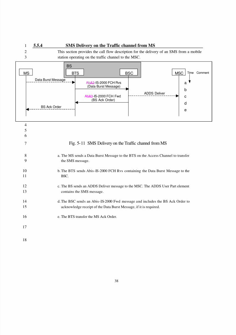
5.5.4 SMS Delivery on the Traffic channel from MS1
This section provides the call flow description for the delivery of an SMS from a mobile2
station operating on the traffic channel to the MSC.3
456
Fig. 5-11 SMS Delivery on the Traffic channel from MS7
a. The MS sends a Data Burst Message to the BTS on the Access Channel to transfer8the SMS message.9
b. The BTS sends Abis -IS-2000 FCH Rvs containing the Data Burst Message to the10
BSC.11
c. The BS sends an ADDS Deliver message to the MSC. The ADDS User Part element12contains the SMS message.13
d. The BSC sends an Abis -IS-2000 Fwd message and includes the BS Ack Order to14acknowledge receipt of the Data Burst Message, if it is required.15
e. The BTS transfer the MS Ack Order.16
17
18
MS BTS MSC
ADDS Deliver
BSC
BS
BS Ack Order
Data Burst MessageAbA3-IS-2000 FCH Rvs (Data Burst Message)
AbA3 -IS-2000 FCH Fwd (BS Ack Order)
a
b
c
d
e
Time Comment
8/2/2019 Abis CDMA2000
http://slidepdf.com/reader/full/abis-cdma2000 42/89
39
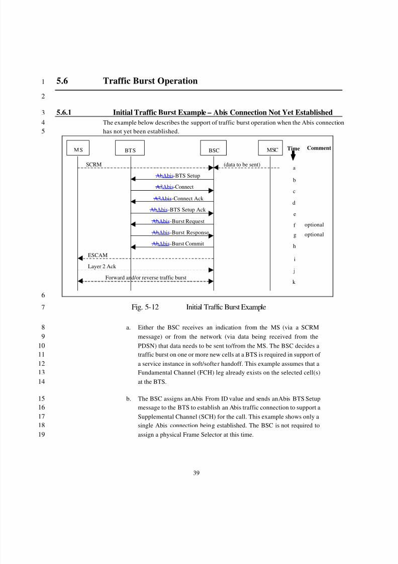
5.6 Traffic Burst Operation1
2
5.6.1 Initial Traffic Burst Example – Abis Connection Not Yet Established3The example below describes the support of traffic burst operation when the Abis connection4has not yet been established.5
M S BTS MSC Time Comment
a
b
c
d
e
f
g
BSC
h
j
i
k
AbAbis -BTS Setup
A3Abis -Connect
A3Abis -Connect Ack
ESCAM
SCRM (data to be sent)
AbAbis -BTS Setup Ack
AbAbis -Burst Request
AbAbis -Burst Response
AbAbis -Burst Commit
Layer 2 Ack
Forward and/or reverse traffic burst
optional
optional
6Fig. 5-12 Initial Traffic Burst Example7
a. Either the BSC receives an indication from the MS (via a SCRM8message) or from the network (via data being received from the9PDSN) that data needs to be sent to/from the MS. The BSC decides a10traffic burst on one or more new cells at a BTS is required in support of 11a service instance in soft/softer handoff. This example assumes that a12Fundamental Channel (FCH) leg already exists on the selected cell(s)13at the BTS.14
b. The BSC assigns an Abis From ID value and sends an Abis BTS Setup15message to the BTS to establish an Abis traffic connection to support a16Supplemental Channel (SCH) for the call. This example shows only a17single Abis connection being established. The BSC is not required to18assign a physical Frame Selector at this time.19
8/2/2019 Abis CDMA2000
http://slidepdf.com/reader/full/abis-cdma2000 43/89
40
c. The BTS assigns a traffic circuit and optionally a Channel Element ID1(CE ID) for each Abis traffic connection and sends an Abis -Connect2message to the BSC indicating the Traffic Circuit ID, optional Abis3
From ID and CE ID to be associated with the specified Abis From ID.4 The BSC and BTS save the association of CE ID, Traffic Circuit ID,5with Cell ID(s). The BSC also saves the Abis From ID value, to be6included in subsequent Abis messages to the BTS. This is only done at7the initial burst.8
d. The BSC responds with an Abis Connect Ack message to complete the9Abis connection. This includes an Abis From ID value assigned by the10BSC, which will be included by the BTS in subsequent Abis messages11to the BSC.12
e. The BTS sends Abis -BTS Setup Ack messages to the BSC to complete13the Abis traffic circuit connection setup procedure for the specified set14of cells. This includes an Abis From ID value assigned by the BTS,15which will be included by the BSC in subsequent Abis messages to the16BTS for this call association.17
When the BSC has knowledge of resources for SCH in the BTS, the18procedure at step f and at step g is not necessary.19
f. The BSC sends an Abis -Burst Request including the Abis to ID to the20BTS to request the reservation of the needed radio resources for the21supplemental channel. Note that the BSC may send an Abis -Burst22Request to the BTS at any time after receiving the Abis -BTS Setup23message in step c, and that the set of cells may be subset of the cells24assigned in step a-e.25
g. The BTS determines that it can reserve part or all of the requested26resources and sends Abis-Burst Response message(s) including Abis27From ID to the BSC indicating the resources that have been reserved28and committed to the traffic burst, and the cause value for any29uncommitted cells. Each reservation includes a physical Channel30Element. Note that the physical Channel Element may be allocated any31time after step b.32
h. The BSC makes a final decision on the resources to be used for the33traffic burst and sends an Abis -Burst Commit message to each BTS34indicating the set of committed resources that will actually be used for35the traffic burst. Note that the BSC may allocate the frame selector any36time after step b. Any resources (cells) not included in the Abis -Burst37Commit message may be released by the BTS.38
8/2/2019 Abis CDMA2000
http://slidepdf.com/reader/full/abis-cdma2000 44/89
41
i. The BSC commands the MS to prepare for the traffic burst via an1ESCAM message.2
j. The MS acknowledges the command from the source BS with a Layer32 Ack.4
k. The network and MS exchange forward and/or reverse traffic burst5information for the specified duration, or until the BSC terminates or6extends the traffic burst.7
8
9
8/2/2019 Abis CDMA2000
http://slidepdf.com/reader/full/abis-cdma2000 45/89
42
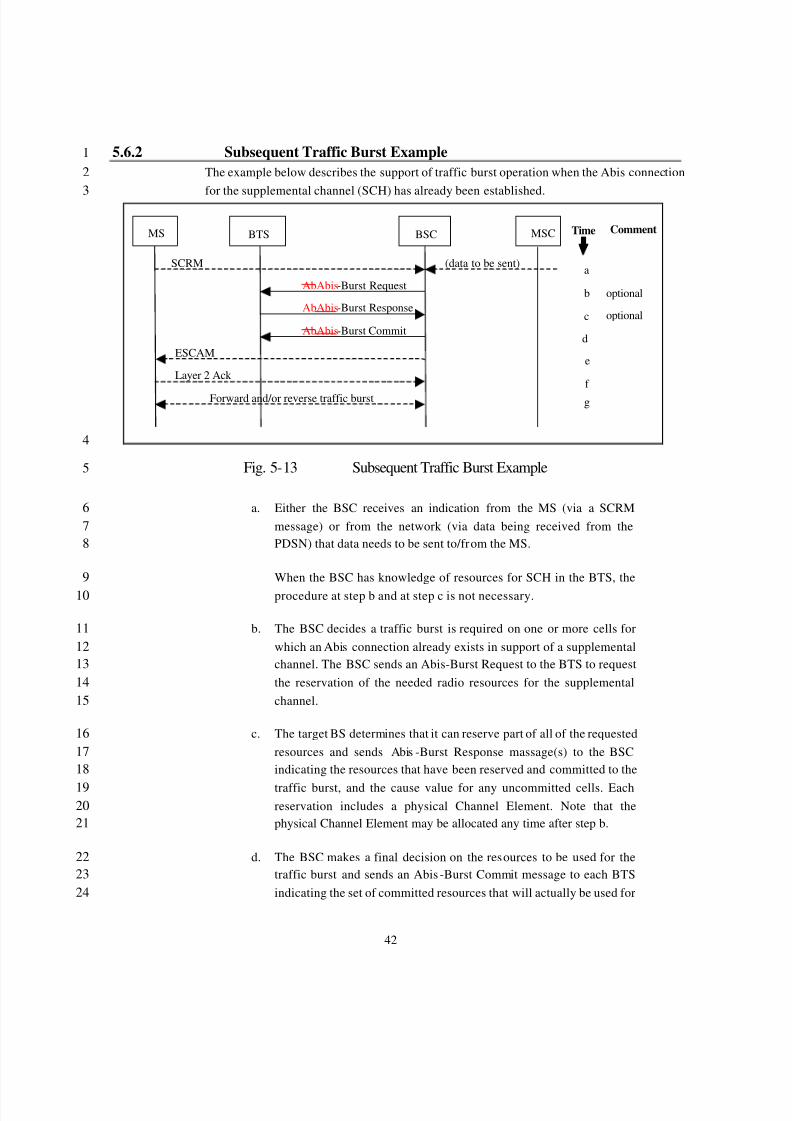
5.6.2 Subsequent Traffic Burst Example1The example below describes the support of traffic burst operation when the Abis connection2
for the supplemental channel (SCH) has already been established.3
MS BTS MSC Time Comment
a
b
c
d
e
f
g
BSC
ESCAM
SCRM (data to be sent)
AbAbis -Burst Request
AbAbis -Burst Response
AbAbis -Burst Commit
Layer 2 Ack
Forward and/or reverse traffic burst
optional
optional
4
Fig. 5-13 Subsequent Traffic Burst Example5
a. Either the BSC receives an indication from the MS (via a SCRM6message) or from the network (via data being received from the7PDSN) that data needs to be sent to/from the MS.8
When the BSC has knowledge of resources for SCH in the BTS, the9procedure at step b and at step c is not necessary.10
b. The BSC decides a traffic burst is required on one or more cells for11which an Abis connection already exists in support of a supplemental12channel. The BSC sends an Abis-Burst Request to the BTS to request13the reservation of the needed radio resources for the supplemental14channel.15
c. The target BS determines that it can reserve part of all of the requested16resources and sends Abis -Burst Response massage(s) to the BSC17indicating the resources that have been reserved and committed to the18
traffic burst, and the cause value for any uncommitted cells. Each19reservation includes a physical Channel Element. Note that the20physical Channel Element may be allocated any time after step b.21
d. The BSC makes a final decision on the resources to be used for the22traffic burst and sends an Abis -Burst Commit message to each BTS23indicating the set of committed resources that will actually be used for24
8/2/2019 Abis CDMA2000
http://slidepdf.com/reader/full/abis-cdma2000 46/89
43
the traffic burst. Note that the BSC may allocate the frame selector any1time after step b. Any resources (cells) not included in the Abis -Burst2Commit message may be released by the BTS.3
e. The BSC commands the MS to prepare for the traffic burst via an4ESCAM message.5
f. The MS acknowledges the command from the source BS with a Layer62 Ack.7
g. The network and MS exchange forward and/or reverse traffic burst8information for the specified duration, or until the BSC terminates or9extends the traffic burst.10
11
12
Abis Interface Message Formats13
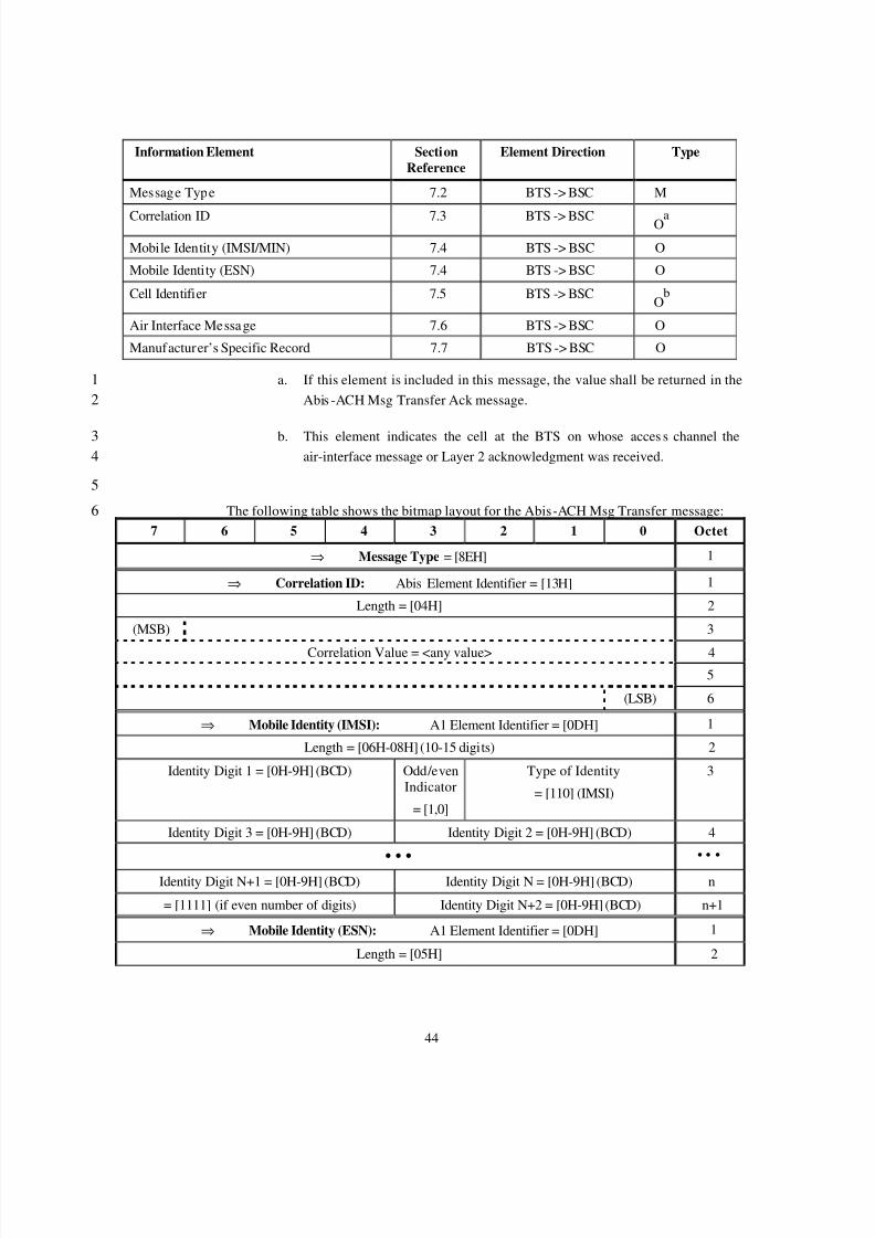
For Abis Interface message there are a number of information elements that are14individually defined in section 6.1. Each information element in a given message is tagged15with a reference in section 6.1, a direction indication (i.e., some elements within a message16are bi-directional and others are not), and a mandatory/optional type (M/O) indicator.17
The inclusion of information elements in each message is specified as follows:18
? M - information elements which are mandatory for the message.19
? O - information elements which are optional for the message.20
6.1 Abis interface message21
22
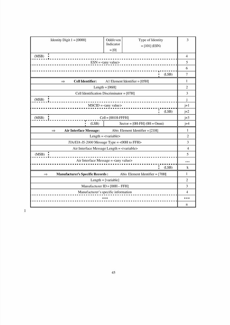
6.1.1 Abis-ACH Msg Transfer23
This Abis interface message is sent from the BTS to the BSC to notify the BSC of the24reception of the contained message or Layer 2 acknowledgment on the specified access25channel.26
8/2/2019 Abis CDMA2000
http://slidepdf.com/reader/full/abis-cdma2000 47/89
44
Information Element SectionReference
Element Direction Type
Message Type 7.2 BTS -> BSC M
Correlation ID 7.3 BTS -> BSC Oa
Mobile Identity (IMSI/MIN) 7.4 BTS -> BSC O
Mobile Identity (ESN) 7.4 BTS -> BSC O
Cell Identifier 7.5 BTS -> BSCO
b
Air Interface Message 7.6 BTS -> BSC O
Manufacturer’s Specific Record 7.7 BTS -> BSC O
a. If this element is included in this message, the value shall be returned in the1Abis -ACH Msg Transfer Ack message.2
b. This element indicates the cell at the BTS on whose acces s channel the3air-interface message or Layer 2 acknowledgment was received.4
5
The following table shows the bitmap layout for the Abis-ACH Msg Transfer message:67 6 5 4 3 2 1 0 Octet
⇒ Message Type = [8EH] 1
⇒ Correlation ID: Abis Element Identifier = [13H] 1
Length = [04H] 2
(MSB) 3
Correlation Value = <any value> 4 5
(LSB) 6
⇒ Mobile Identity (IMSI): A1 Element Identifier = [0DH] 1
Length = [06H-08H] (10-15 digits) 2
Identity Digit 1 = [0H-9H] (BCD) Odd/evenIndicator
= [1,0]
Type of Identity
= [110] (IMSI)
3
Identity Digit 3 = [0H-9H] (BCD) Identity Digit 2 = [0H-9H] (BCD) 4
• • • • • •
Identity Digit N+1 = [0H-9H] (BCD) Identity Digit N = [0H-9H] (BCD) n
= [1111] (if even number of digits) Identity Digit N+2 = [0H-9H] (BCD) n+1
⇒ Mobile Identity (ESN): A1 Element Identifier = [0DH] 1
Length = [05H] 2
8/2/2019 Abis CDMA2000
http://slidepdf.com/reader/full/abis-cdma2000 48/89
45
Identity Digit 1 = [0000] Odd/evenIndicator
= [0]
Type of Identity
= [101] (ESN)
3
(MSB) 4ESN = <any value> 5
6
(LSB) 7
⇒ Cell Identifier: A1 Element Identifier = [05H] 1
Length = [06H] 2
Cell Identification Discriminator = [07H] 3
(MSB) j
MSCID = <any value> j+1
(LSB) j+2
(MSB) Cell = [001H-FFFH] j+3
(LSB) Sector = [0H-FH] (0H = Omni) j+4
⇒ Air Interface Message: Abis Element Identifier = [21H] 1
Length = <variable> 2
TIA/EIA-IS-2000 Message Type = <00H to FFH> 3
Air Interface Message Length = <variable> 4
(MSB) 5
Air Interface Message = <any value> …(LSB) k
⇒ Manufacturer’s Specific Records : Abis Element Identifier = [70H] 1
Length = [variable] 2
Manufacturer ID = [00H – FFH] 3
Manufacturer’s specific information 4
• • • • • •
n
1
8/2/2019 Abis CDMA2000
http://slidepdf.com/reader/full/abis-cdma2000 49/89
46
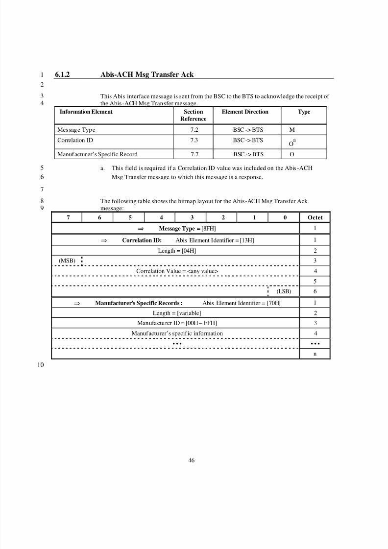
6.1.2 Abis-ACH Msg Transfer Ack1
2
This Abis interface message is sent from the BSC to the BTS to acknowledge the receipt of 3the Abis -ACH Msg Transfer message.4
Information Element SectionReference
Element Direction Type
Message Type 7.2 BSC -> BTS M
Correlation ID 7.3 BSC -> BTSO
a
Manufacturer’s Specific Record 7.7 BSC -> BTS O
a. This field is required if a Correlation ID value was included on the Abis -ACH5Msg Transfer message to which this message is a response.6
7The following table shows the bitmap layout for the Abis-ACH Msg Transfer Ack 8message:9
7 6 5 4 3 2 1 0 Octet
⇒ Message Type = [8FH] 1
⇒ Correlation ID: Abis Element Identifier = [13H] 1
Length = [04H] 2
(MSB) 3
Correlation Value = <any value> 4
5
(LSB) 6
⇒ Manufacturer’s Specific Records : Abis Element Identifier = [70H] 1
Length = [variable] 2
Manufacturer ID = [00H – FFH] 3
Manufacturer’s specific information 4
• • • • • •
n
10
8/2/2019 Abis CDMA2000
http://slidepdf.com/reader/full/abis-cdma2000 50/89
47
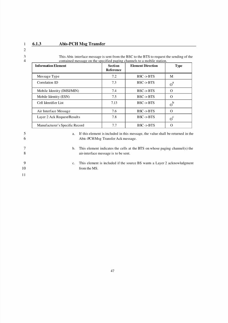
6.1.3 Abis-PCH Msg Transfer1
2
This Abis interface message is sent from the BSC to the BTS to request the sending of the3contained message on the specified paging channels to a mobile station.4
Information Element SectionReference
Element Direction Type
Message Type 7.2 BSC -> BTS M
Correlation ID 7.3 BSC -> BTSO
a
Mobile Identity (IMSI/MIN) 7.4 BSC -> BTS O
Mobile Identity (ESN) 7.5 BSC -> BTS O
Cell Identifier List 7.13 BSC -> BTSO
b
Air Interface Message 7.6 BSC -> BTS O
Layer 2 Ack Request/Results 7.8 BSC -> BTSO
c
Manufacturer’s Specific Record 7.7 BSC -> BTS O
a. If this element is included in this message, the value shall be returned in the5Abis -PCH Msg Transfer Ack message.6
b. This element indicates the cells at the BTS on whose paging channel(s) the7air-interface message is to be sent.8
c. This element is included if the source BS wants a Layer 2 acknowledgment9
from the MS.1011
8/2/2019 Abis CDMA2000
http://slidepdf.com/reader/full/abis-cdma2000 51/89
48
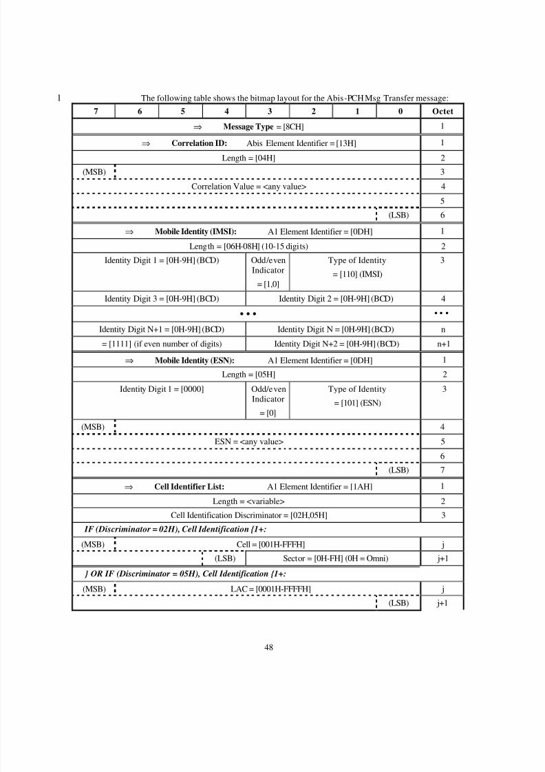
The following table shows the bitmap layout for the Abis-PCH Msg Transfer message:17 6 5 4 3 2 1 0 Octet
⇒ Message Type = [8CH] 1
⇒ Correlation ID: Abis Element Identifier = [13H] 1
Length = [04H] 2
(MSB) 3
Correlation Value = <any value> 4
5
(LSB) 6
⇒ Mobile Identity (IMSI): A1 Element Identifier = [0DH] 1
Length = [06H-08H] (10-15 digits) 2
Identity Digit 1 = [0H-9H] (BCD) Odd/even
Indicator= [1,0]
Type of Identity
= [110] (IMSI)
3
Identity Digit 3 = [0H-9H] (BCD) Identity Digit 2 = [0H-9H] (BCD) 4
• • • • • •
Identity Digit N+1 = [0H-9H] (BCD) Identity Digit N = [0H-9H] (BCD) n
= [1111] (if even number of digits) Identity Digit N+2 = [0H-9H] (BCD) n+1
⇒ Mobile Identity (ESN): A1 Element Identifier = [0DH] 1
Length = [05H] 2
Identity Digit 1 = [0000] Odd/evenIndicator
= [0]
Type of Identity
= [101] (ESN)
3
(MSB) 4
ESN = <any value> 5
6
(LSB) 7
⇒ Cell Identifier List: A1 Element Identifier = [1AH] 1
Length = <variable> 2
Cell Identification Discriminator = [02H,05H] 3
IF (Discriminator = 02H), Cell Identification {1+:
(MSB) Cell = [001H-FFFH] j
(LSB) Sector = [0H-FH] (0H = Omni) j+1
} OR IF (Discriminator = 05H), Cell Identification {1+:
(MSB) LAC = [0001H-FFFFH] j
(LSB) j+1
8/2/2019 Abis CDMA2000
http://slidepdf.com/reader/full/abis-cdma2000 52/89
49
} Cell Identification
⇒ Air Interface Message: Abis Element Identifier = [21H] 1
Length = <variable> 2
TIA/EIA-IS-2000 Message Type = <00H to FFH> 3
Air Interface Message Length = <variable> 4
(MSB) 5
Air Interface Message = <any value> …(LSB) k
⇒ Layer 2 Ack Request/Results: Abis Element Identifier = [23H] 1
Length = [01H] 2
Reserved = [0000 000] Layer 2Ack
= [0/1]
3
⇒ Manufacturer’s Specific Records : Abis Element Identifier = [70H] 1
Length = [variable] 2
Manufacturer ID = [00H – FFH] 3
Manufacturer’s specific information 4
• • • • • •
n
1
2
3
45
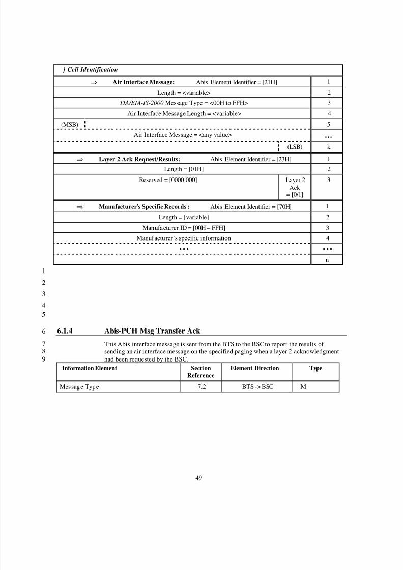
6.1.4 Abis-PCH Msg Transfer Ack6
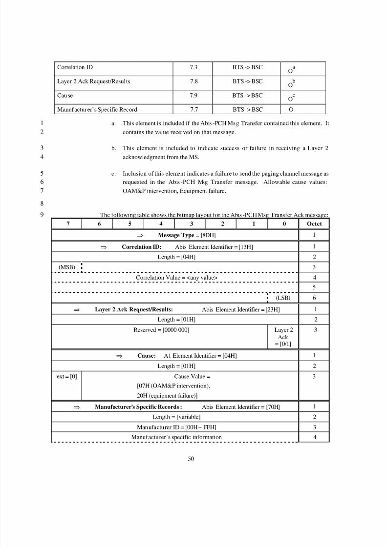
This Abis interface message is sent from the BTS to the BSC to report the results of 7sending an air interface message on the specified paging when a layer 2 acknowledgment8had been requested by the BSC.9
Information Element SectionReference
Element Direction Type
Message Type 7.2 BTS -> BSC M
8/2/2019 Abis CDMA2000
http://slidepdf.com/reader/full/abis-cdma2000 53/89
8/2/2019 Abis CDMA2000
http://slidepdf.com/reader/full/abis-cdma2000 54/89
51
• • • • • •
n
123
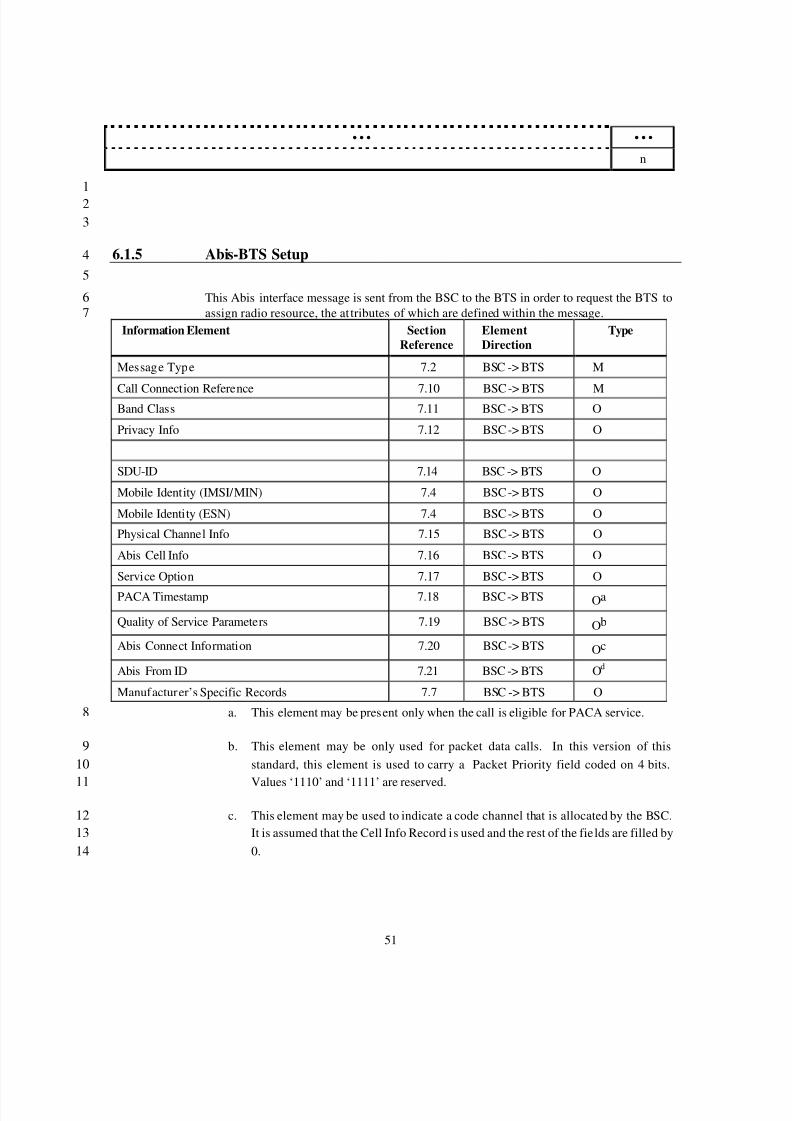
6.1.5 Abis-BTS Setup4
5
This Abis interface message is sent from the BSC to the BTS in order to request the BTS to6assign radio resource, the at tributes of which are defined within the message.7
Information Element SectionReference
ElementDirection
Type
Message Type 7.2 BSC -> BTS M
Call Connection Reference 7.10 BSC -> BTS MBand Class 7.11 BSC -> BTS O
Privacy Info 7.12 BSC -> BTS O
SDU-ID 7.14 BSC -> BTS O
Mobile Identity (IMSI/MIN) 7.4 BSC -> BTS O
Mobile Identity (ESN) 7.4 BSC -> BTS O
Physical Channel Info 7.15 BSC -> BTS O
Abis Cell Info 7.16 BSC -> BTS O
Service Option 7.17 BSC -> BTS O
PACA Timestamp 7.18 BSC -> BTS Oa
Quality of Service Parameters 7.19 BSC -> BTS Ob
Abis Connect Information 7.20 BSC -> BTS Oc
Abis From ID 7.21 BSC -> BTS O d
Manufacturer’s Specific Records 7.7 BSC -> BTS O
a. This element may be present only when the call is eligible for PACA service.8
b. This element may be only used for packet data calls. In this version of this9standard, this element is used to carry a Packet Priority field coded on 4 bits.10
Values ‘1110’ and ‘1111’ are reserved.11
c. This element may be used to indicate a code channel that is allocated by the BSC.12It is assumed that the Cell Info Record i s used and the rest of the fie lds are filled by130.14

8/2/2019 Abis CDMA2000
http://slidepdf.com/reader/full/abis-cdma2000 55/89
52
d. This element is optionally included by the BTS. If included, the value shall be1saved and used by the BSC in subsequent Abis message for this call association.2
3
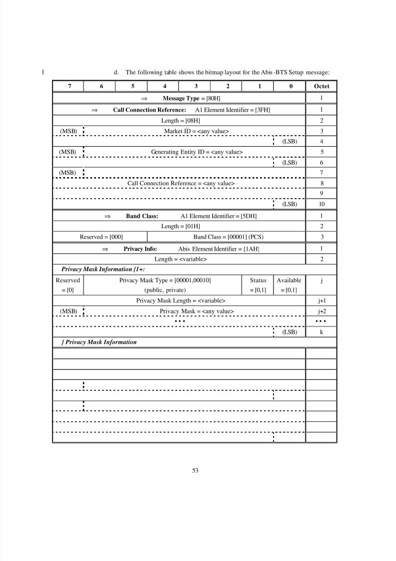
8/2/2019 Abis CDMA2000
http://slidepdf.com/reader/full/abis-cdma2000 56/89
53
d. The following table shows the bitmap layout for the Abis -BTS Setup message:1
7 6 5 4 3 2 1 0 Octet
⇒ Message Type = [80H] 1⇒ Call Connection Reference: A1 Element Identifier = [3FH] 1
Length = [08H] 2
(MSB) Market ID = <any value> 3
(LSB) 4
(MSB) Generating Entity ID = <any value> 5
(LSB) 6
(MSB) 7
Call Connection Reference = <any value> 8
9(LSB) 10
⇒ Band Class: A1 Element Identifier = [5DH] 1
Length = [01H] 2
Reserved = [000] Band Class = [00001] (PCS) 3
⇒ Privacy Info: Abis Element Identifier = [1AH] 1
Length = <variable> 2
Privacy Mask Information {1+:
Reserved
= [0]
Privacy Mask Type = [00001,00010]
(public, private)
Status
= [0,1]
Available
= [0,1]
j
Privacy Mask Length = <variable> j+1
(MSB) Privacy Mask = <any value> j+2
• • • • • •
(LSB) k
} Privacy Mask Information
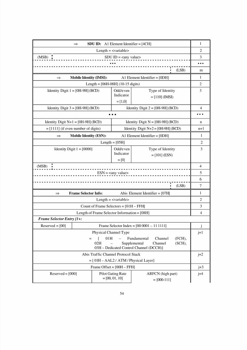
8/2/2019 Abis CDMA2000
http://slidepdf.com/reader/full/abis-cdma2000 57/89
54
⇒ SDU ID: A1 Element Identifier = [4CH] 1
Length = <variable> 2
(MSB) SDU ID = <any value> 3
• • • • • •
(LSB) m
⇒ Mobile Identity (IMSI): A1 Element Identifier = [0DH] 1
Length = [06H-08H] (10-15 digits) 2
Identity Digit 1 = [0H-9H] (BCD) Odd/evenIndicator
= [1,0]
Type of Identity
= [110] (IMSI)
3
Identity Digit 3 = [0H-9H] (BCD) Identity Digit 2 = [0H-9H] (BCD) 4
• • • • • •
Identity Digit N+1 = [0H-9H] (BCD) Identity Digit N = [0H-9H] (BCD) n= [1111] (if even number of digits) Identity Digit N+2 = [0H-9H] (BCD) n+1
⇒ Mobile Identity (ESN): A1 Element Identifier = [0DH] 1
Length = [05H] 2
Identity Digit 1 = [0000] Odd/evenIndicator
= [0]
Type of Identity
= [101] (ESN)
3
(MSB) 4
ESN = <any value> 5
6
(LSB) 7
⇒ Frame Selector Info: Abis Element Identifier = [07H] 1
Length = <variable> 2
Count of Frame Selectors = [01H – FFH] 3
Length of Frame Selector Information = [08H] 4
Frame Selector Entry {1+:
Reserved = [00] Frame Selector Index = [00 0001 – 11 1111] j
Physical Channel Type
= [ 01H – Fundamental Channel (FCH),02H – Supplemental Channel (SCH),03H – Dedicated Control Channel (DCCH)]
j+1
Abis Traffic Channel Protocol Stack
= [ 01H – AAL2 / ATM / Physical Layer]
j+2
Frame Offset = [00H – FFH] j+3
Reserved = [000] Pilot Gating Rate= [00, 01, 10]
ARFCN (high part)
= [000-111]
j+4
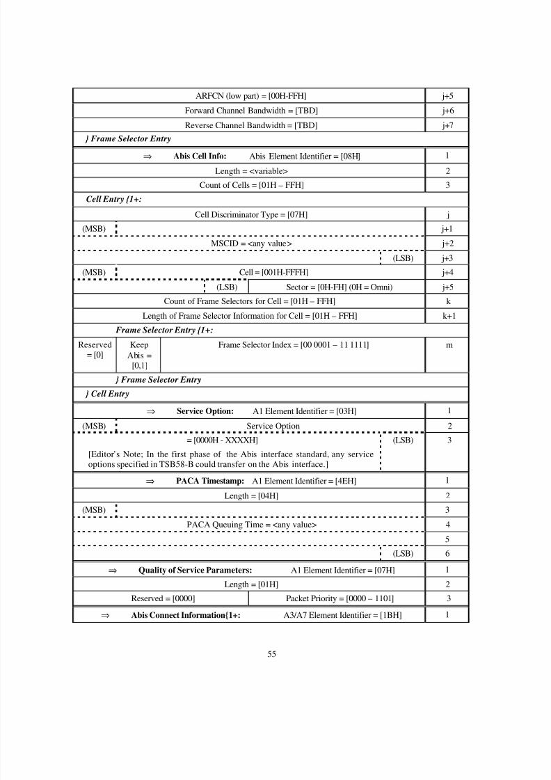
8/2/2019 Abis CDMA2000
http://slidepdf.com/reader/full/abis-cdma2000 58/89
55
ARFCN (low part) = [00H-FFH] j+5
Forward Channel Bandwidth = [TBD] j+6
Reverse Channel Bandwidth = [TBD] j+7
} Frame Selector Entry
⇒ Abis Cell Info: Abis Element Identifier = [08H] 1
Length = <variable> 2
Count of Cells = [01H – FFH] 3
Cell Entry {1+:
Cell Discriminator Type = [07H] j
(MSB) j+1
MSCID = <any value> j+2
(LSB) j+3
(MSB) Cell = [001H-FFFH] j+4(LSB) Sector = [0H-FH] (0H = Omni) j+5
Count of Frame Selectors for Cell = [01H – FFH] k
Length of Frame Selector Information for Cell = [01H – FFH] k+1
Frame Selector Entry {1+:
Reserved= [0]
KeepAbis =
[0,1]
Frame Selector Index = [00 0001 – 11 1111] m
} Frame Selector Entry
} Cell Entry
⇒ Service Option: A1 Element Identifier = [03H] 1(MSB) Service Option 2
= [0000H - XXXXH]
[Editor’s Note; In the first phase of the Abis interface standard, any serviceoptions specified in TSB58-B could transfer on the Abis interface.]
(LSB) 3
⇒ PACA Timestamp: A1 Element Identifier = [4EH] 1
Length = [04H] 2
(MSB) 3
PACA Queuing Time = <any value> 4
5
(LSB) 6
⇒ Quality of Service Parameters: A1 Element Identifier = [07H] 1
Length = [01H] 2
Reserved = [0000] Packet Priority = [0000 – 1101] 3
⇒ Abis Connect Information{1+: A3/A7 Element Identifier = [1BH] 1
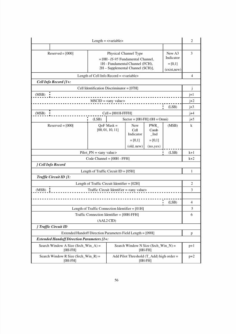
8/2/2019 Abis CDMA2000
http://slidepdf.com/reader/full/abis-cdma2000 59/89
56
Length = <variable> 2
Reserved = [000] Physical Channel Type
= [0H - IS-95 Fundamental Channel,1H – Fundamental Channel (FCH),2H – Supplemental Channel (SCH)],
New A3
Indicator= [0,1]
(exist,new)
3
Length of Cell Info Record = <variable> 4
Cell Info Record {1+:
Cell Identification Discriminator = [07H] j
(MSB) j+1
MSCID = <any value> j+2
(LSB) j+3
(MSB) Cell = [001H-FFFH] j+4
(LSB) Sector = [0H-FH] (0H = Omni) j+5
Reserved = [000] QoF Mask =[00, 01, 10, 11]
NewCell
Indicator
= [0,1]
(old, new)
PWR_Comb_Ind
= [0,1]
(no,yes)
(MSB) k
Pilot_PN = <any value> (LSB) k+1
Code Channel = [00H - FFH] k+2
} Cell Info Record
Length of Traffic Circuit ID = [05H] 1
Traffic Circuit ID {1:
Length of Traffic Circuit Identifier = [02H] 2
(MSB) Traffic Circuit Identifier = <any value> 3
(LSB) 4
Length of Traffic Connection Identifier = [01H] 5
Traffic Connection Identifier = [00H-FFH]
(AAL2 CID)
6
} Traffic Circuit ID
Extended Handoff Direction Parameters Field Length = [09H] p Extended Handoff Direction Parameters {1+:
Search Window A Size (Srch_Win_A) =[0H-FH]
Search Window N Size (Srch_Win_N) =[0H-FH]
p+1
Search Window R Size (Srch_Win_R) =[0H-FH]
Add Pilot Threshold (T_Add) high order =[0H-FH]
p+2
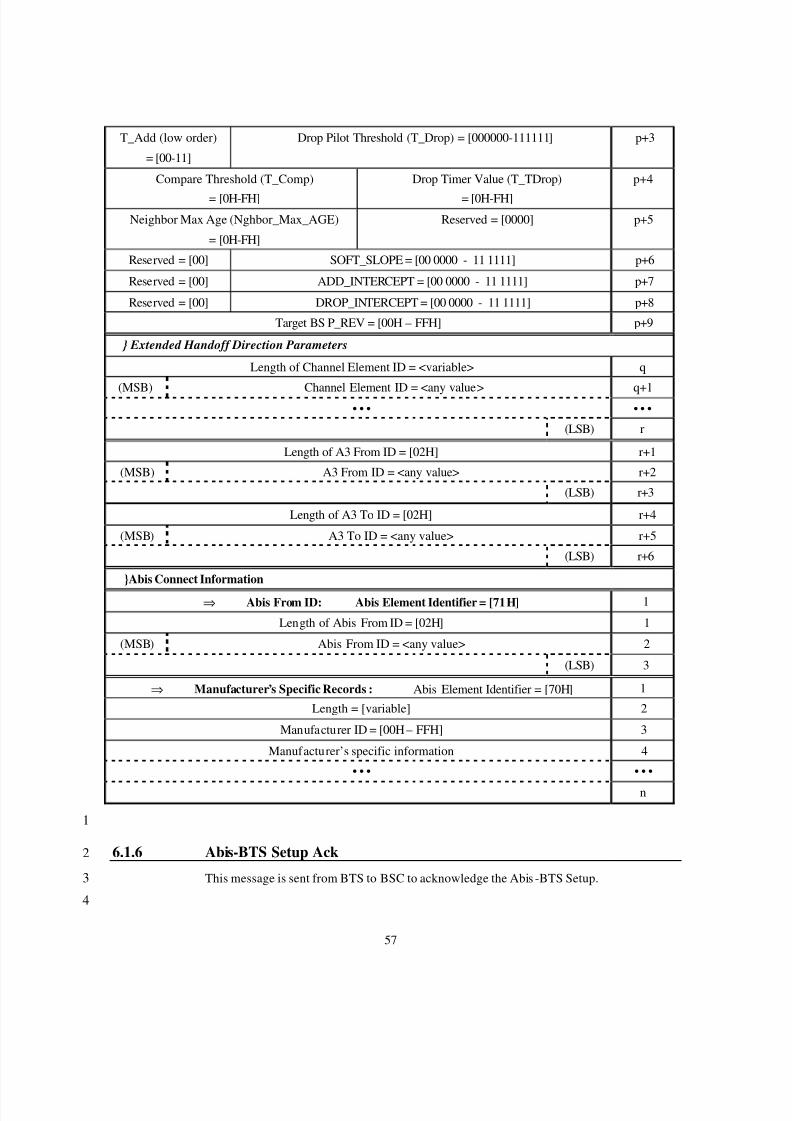
8/2/2019 Abis CDMA2000
http://slidepdf.com/reader/full/abis-cdma2000 60/89
57
T_Add (low order)
= [00-11]
Drop Pilot Threshold (T_Drop) = [000000-111111] p+3
Compare Threshold (T_Comp)
= [0H-FH]
Drop Timer Value (T_TDrop)
= [0H-FH]
p+4
Neighbor Max Age (Nghbor_Max_AGE)
= [0H-FH]
Reserved = [0000] p+5
Reserved = [00] SOFT_SLOPE = [00 0000 - 11 1111] p+6
Reserved = [00] ADD_INTERCEPT = [00 0000 - 11 1111] p+7
Reserved = [00] DROP_INTERCEPT = [00 0000 - 11 1111] p+8
Target BS P_REV = [00H – FFH] p+9
} Extended Handoff Direction Parameters
Length of Channel Element ID = <variable> q
(MSB) Channel Element ID = <any value> q+1• • • • • •
(LSB) r
Length of A3 From ID = [02H] r+1
(MSB) A3 From ID = <any value> r+2
(LSB) r+3
Length of A3 To ID = [02H] r+4
(MSB) A3 To ID = <any value> r+5
(LSB) r+6
}Abis Connect Information
⇒ Abis From ID: Abis Element Identifier = [71H] 1
Length of Abis From ID = [02H] 1
(MSB) Abis From ID = <any value> 2
(LSB) 3
⇒ Manufacturer’s Specific Records : Abis Element Identifier = [70H] 1
Length = [variable] 2
Manufacturer ID = [00H – FFH] 3
Manufacturer’s specific information 4
• • • • • •
n
1
6.1.6 Abis-BTS Setup Ack2
This message is sent from BTS to BSC to acknowledge the Abis -BTS Setup.3
4
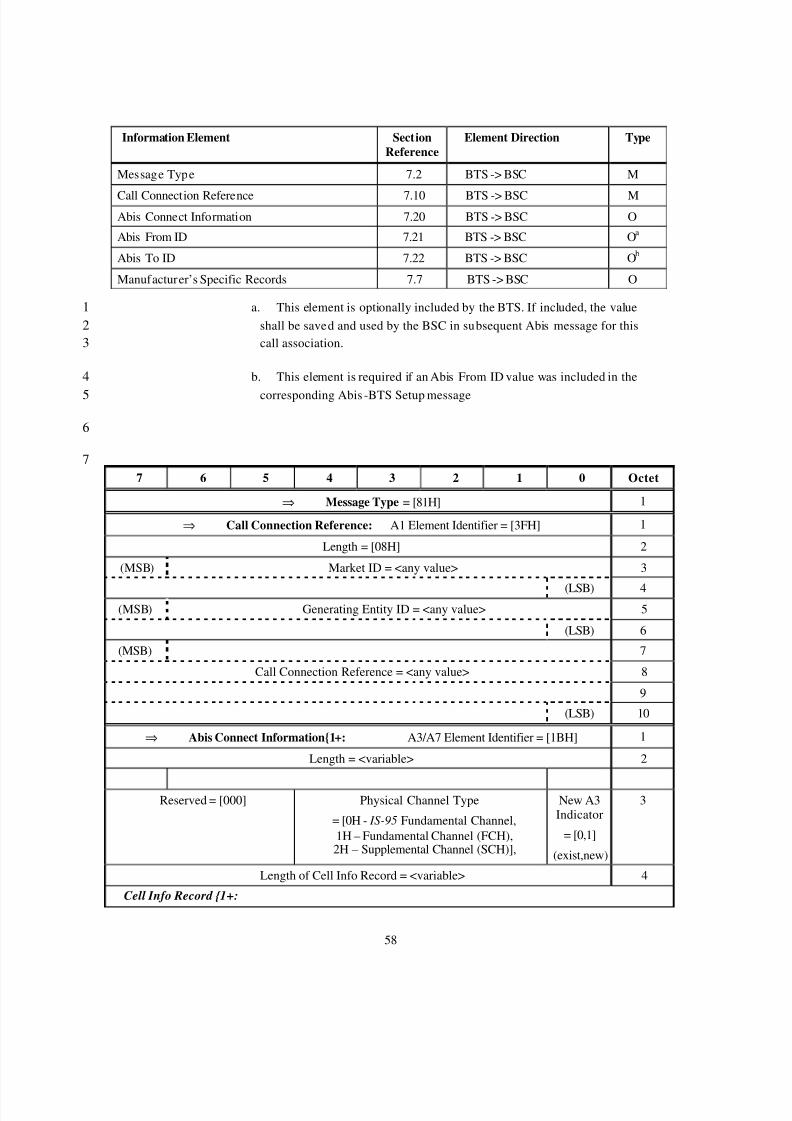
8/2/2019 Abis CDMA2000
http://slidepdf.com/reader/full/abis-cdma2000 61/89
58
Information Element SectionReference
Element Direction Type
Message Type 7.2 BTS -> BSC M
Call Connection Reference 7.10 BTS -> BSC MAbis Connect Information 7.20 BTS -> BSC O
Abis From ID 7.21 BTS -> BSC O a
Abis To ID 7.22 BTS -> BSC O b
Manufacturer’s Specific Records 7.7 BTS -> BSC O
a. This element is optionally included by the BTS. If included, the value1shall be saved and used by the BSC in subsequent Abis message for this2call association.3
b. This element is required if an Abis From ID value was included in the4
corresponding Abis -BTS Setup message5
6
77 6 5 4 3 2 1 0 Octet
⇒ Message Type = [81H] 1
⇒ Call Connection Reference: A1 Element Identifier = [3FH] 1
Length = [08H] 2
(MSB) Market ID = <any value> 3
(LSB) 4(MSB) Generating Entity ID = <any value> 5
(LSB) 6
(MSB) 7
Call Connection Reference = <any value> 8
9
(LSB) 10
⇒ Abis Connect Information{1+: A3/A7 Element Identifier = [1BH] 1
Length = <variable> 2
Reserved = [000] Physical Channel Type
= [0H - IS-95 Fundamental Channel,1H – Fundamental Channel (FCH),2H – Supplemental Channel (SCH)],
New A3Indicator
= [0,1]
(exist,new)
3
Length of Cell Info Record = <variable> 4
Cell Info Record {1+:
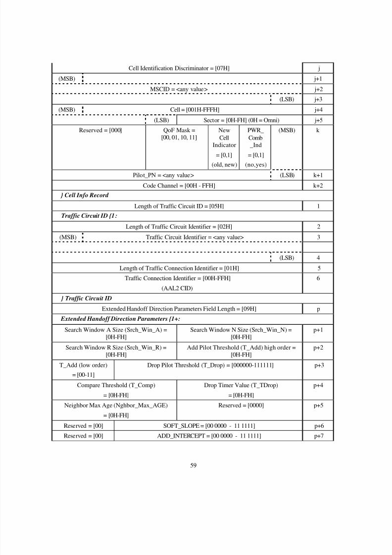
8/2/2019 Abis CDMA2000
http://slidepdf.com/reader/full/abis-cdma2000 62/89
59
Cell Identification Discriminator = [07H] j
(MSB) j+1
MSCID = <any value> j+2
(LSB) j+3
(MSB) Cell = [001H-FFFH] j+4
(LSB) Sector = [0H-FH] (0H = Omni) j+5
Reserved = [000] QoF Mask =[00, 01, 10, 11]
NewCell
Indicator
= [0,1]
(old, new)
PWR_Comb_Ind
= [0,1]
(no,yes)
(MSB) k
Pilot_PN = <any value> (LSB) k+1
Code Channel = [00H - FFH] k+2
} Cell Info Record
Length of Traffic Circuit ID = [05H] 1
Traffic Circuit ID {1:
Length of Traffic Circuit Identifier = [02H] 2
(MSB) Traffic Circuit Identifier = <any value> 3
(LSB) 4
Length of Traffic Connection Identifier = [01H] 5
Traffic Connection Identifier = [00H-FFH]
(AAL2 CID)
6
} Traffic Circuit ID
Extended Handoff Direction Parameters Field Length = [09H] p
Extended Handoff Direction Parameters {1+:
Search Window A Size (Srch_Win_A) =[0H-FH]
Search Window N Size (Srch_Win_N) =[0H-FH]
p+1
Search Window R Size (Srch_Win_R) =[0H-FH]
Add Pilot Threshold (T_Add) high order =[0H-FH]
p+2
T_Add (low order)
= [00-11]
Drop Pilot Threshold (T_Drop) = [000000-111111] p+3
Compare Threshold (T_Comp)
= [0H-FH]
Drop Timer Value (T_TDrop)
= [0H-FH]
p+4
Neighbor Max Age (Nghbor_Max_AGE)
= [0H-FH]
Reserved = [0000] p+5
Reserved = [00] SOFT_SLOPE = [00 0000 - 11 1111] p+6
Reserved = [00] ADD_INTERCEPT = [00 0000 - 11 1111] p+7
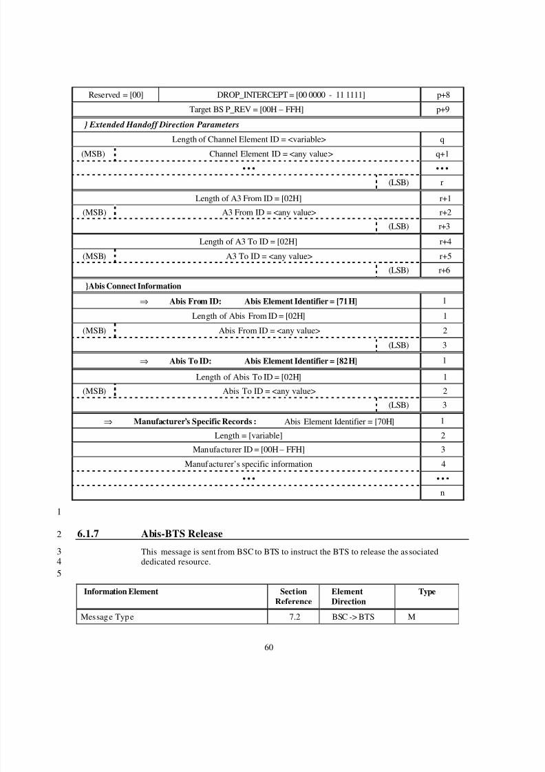
8/2/2019 Abis CDMA2000
http://slidepdf.com/reader/full/abis-cdma2000 63/89
60
Reserved = [00] DROP_INTERCEPT = [00 0000 - 11 1111] p+8
Target BS P_REV = [00H – FFH] p+9
} Extended Handoff Direction Parameters
Length of Channel Element ID = <variable> q
(MSB) Channel Element ID = <any value> q+1
• • • • • •
(LSB) r
Length of A3 From ID = [02H] r+1
(MSB) A3 From ID = <any value> r+2
(LSB) r+3
Length of A3 To ID = [02H] r+4
(MSB) A3 To ID = <any value> r+5
(LSB) r+6}Abis Connect Information
⇒ Abis From ID: Abis Element Identifier = [71H] 1
Length of Abis From ID = [02H] 1
(MSB) Abis From ID = <any value> 2
(LSB) 3
⇒ Abis To ID: Abis Element Identifier = [82H] 1
Length of Abis To ID = [02H] 1
(MSB) Abis To ID = <any value> 2
(LSB) 3⇒ Manufacturer’s Specific Records : Abis Element Identifier = [70H] 1
Length = [variable] 2
Manufacturer ID = [00H – FFH] 3
Manufacturer’s specific information 4
• • • • • •
n
1
6.1.7 Abis-BTS Release2
This message is sent from BSC to BTS to instruct the BTS to release the associated3dedicated resource.4
5
Information Element SectionReference
ElementDirection
Type
Message Type 7.2 BSC -> BTS M
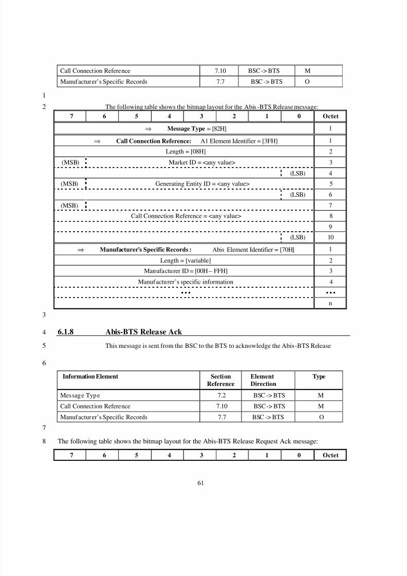
8/2/2019 Abis CDMA2000
http://slidepdf.com/reader/full/abis-cdma2000 64/89
61
Call Connection Reference 7.10 BSC -> BTS M
Manufacturer’s Specific Records 7.7 BSC -> BTS O
1
The following table shows the bitmap layout for the Abis -BTS Release message:27 6 5 4 3 2 1 0 Octet
⇒ Message Type = [82H] 1
⇒ Call Connection Reference: A1 Element Identifier = [3FH] 1
Length = [08H] 2
(MSB) Market ID = <any value> 3
(LSB) 4
(MSB) Generating Entity ID = <any value> 5
(LSB) 6
(MSB) 7
Call Connection Reference = <any value> 8
9
(LSB) 10
⇒ Manufacturer’s Specific Records : Abis Element Identifier = [70H] 1
Length = [variable] 2
Manufacturer ID = [00H – FFH] 3
Manufacturer’s specific information 4
• • • • • •
n
3
6.1.8 Abis-BTS Release Ack4
This message is sent from the BSC to the BTS to acknowledge the Abis-BTS Release5
6
Information Element SectionReference
ElementDirection
Type
Message Type 7.2 BSC -> BTS M
Call Connection Reference 7.10 BSC -> BTS M
Manufacturer’s Specific Records 7.7 BSC -> BTS O
7
The following table shows the bitmap layout for the Abis-BTS Release Request Ack message:8
7 6 5 4 3 2 1 0 Octet
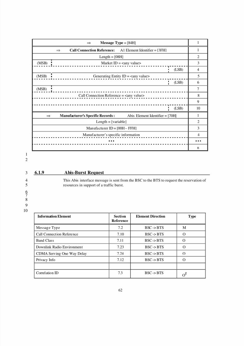
8/2/2019 Abis CDMA2000
http://slidepdf.com/reader/full/abis-cdma2000 65/89
62
⇒ Message Type = [84H] 1
⇒ Call Connection Reference: A1 Element Identifier = [3FH] 1
Length = [08H] 2
(MSB) Market ID = <any value> 3
(LSB) 4
(MSB) Generating Entity ID = <any value> 5
(LSB) 6
(MSB) 7
Call Connection Reference = <any value> 8
9
(LSB) 10
⇒ Manufacturer’s Specific Records : Abis Element Identifier = [70H] 1
Length = [variable] 2Manufacturer ID = [00H – FFH] 3
Manufacturer’s specific information 4
• • • • • •
n
12
6.1.9 Abis-Burst Request3
This Abis interface message is sent from the BSC to the BTS to request the reservation of 4 resources in support of a traffic burst.5
6789
10Information Element Section
ReferenceElement Direction Type
Message Type 7.2 BSC -> BTS M
Call Connection Reference 7.10 BSC -> BTS O
Band Class 7.11 BSC -> BTS O
Downlink Radio Environment 7.23 BSC -> BTS O
CDMA Serving One Way Delay 7.24 BSC -> BTS O
Privacy Info 7.12 BSC -> BTS O
Correlation ID 7.3 BSC -> BTSO
g
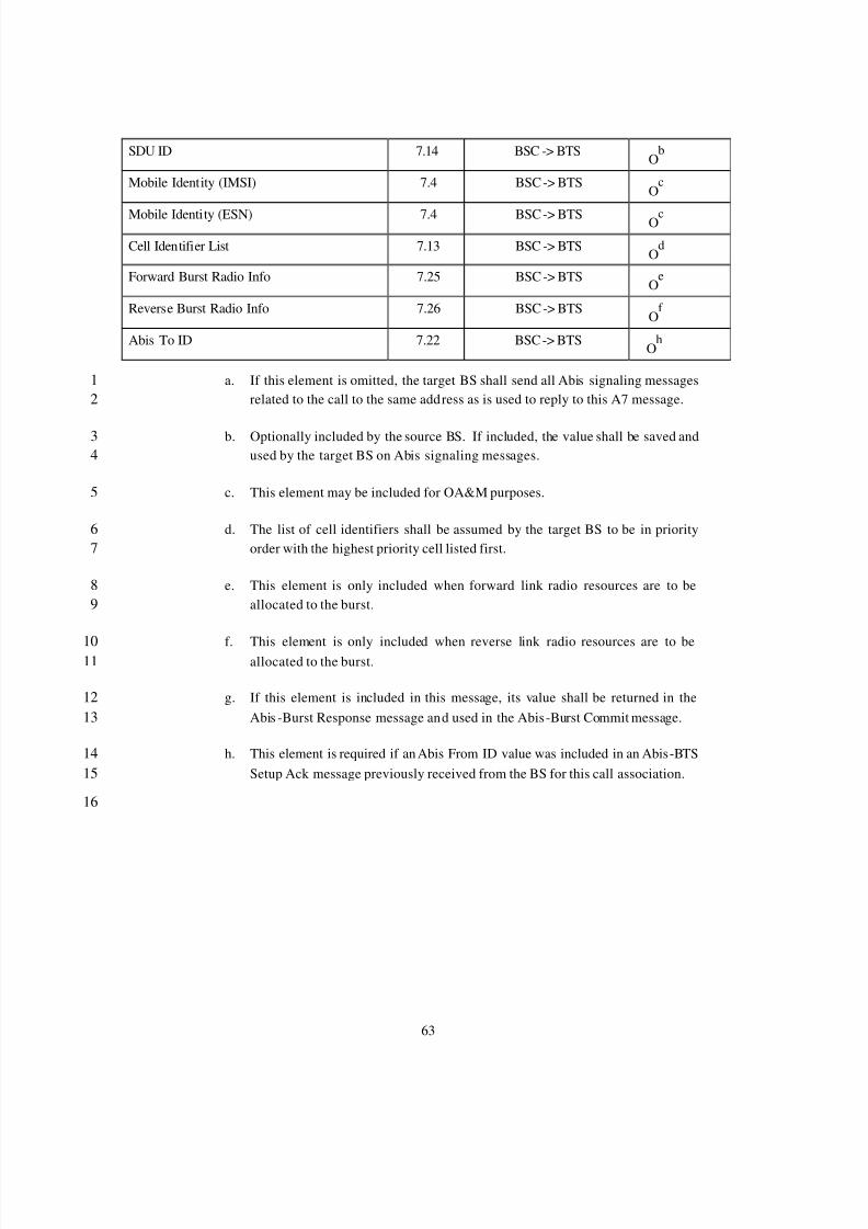
8/2/2019 Abis CDMA2000
http://slidepdf.com/reader/full/abis-cdma2000 66/89
63
SDU ID 7.14 BSC -> BTSO
b
Mobile Identity (IMSI) 7.4 BSC -> BTSO
c
Mobile Identity (ESN) 7.4 BSC -> BTS Oc
Cell Identifier List 7.13 BSC -> BTSO
d
Forward Burst Radio Info 7.25 BSC -> BTSO
e
Reverse Burst Radio Info 7.26 BSC -> BTSO
f
Abis To ID 7.22 BSC -> BTSO
h
a. If this element is omitted, the target BS shall send all Abis signaling messages1related to the call to the same address as is used to reply to this A7 message.2
b. Optionally included by the source BS. If included, the value shall be saved and3used by the target BS on Abis signaling messages.4
c. This element may be included for OA&M purposes.5
d. The list of cell identifiers shall be assumed by the target BS to be in priority6order with the highest priority cell listed first.7
e. This element is only included when forward link radio resources are to be8allocated to the burst.9
f. This element is only included when reverse link radio resources are to be10allocated to the burst.11
g. If this element is included in this message, its value shall be returned in the12Abis -Burst Response message and used in the Abis-Burst Commit message.13
h. This element is required if an Abis From ID value was included in an Abis-BTS14Setup Ack message previously received from the BS for this call association.15
16
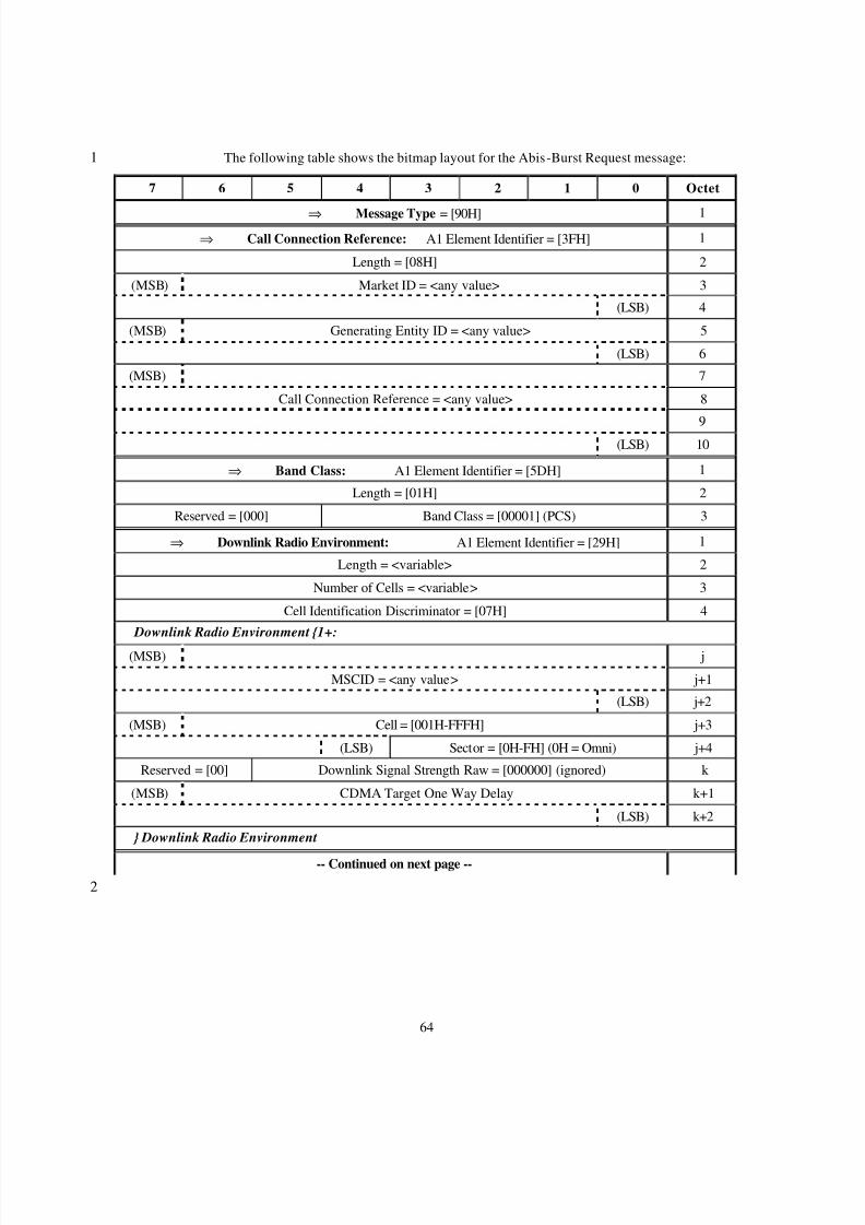
8/2/2019 Abis CDMA2000
http://slidepdf.com/reader/full/abis-cdma2000 67/89
64
The following table shows the bitmap layout for the Abis-Burst Request message:1
7 6 5 4 3 2 1 0 Octet
⇒ Message Type = [90H] 1⇒ Call Connection Reference: A1 Element Identifier = [3FH] 1
Length = [08H] 2
(MSB) Market ID = <any value> 3
(LSB) 4
(MSB) Generating Entity ID = <any value> 5
(LSB) 6
(MSB) 7
Call Connection Reference = <any value> 8
9
(LSB) 10
⇒ Band Class: A1 Element Identifier = [5DH] 1
Length = [01H] 2
Reserved = [000] Band Class = [00001] (PCS) 3
⇒ Downlink Radio Environment: A1 Element Identifier = [29H] 1
Length = <variable> 2
Number of Cells = <variable> 3
Cell Identification Discriminator = [07H] 4
Downlink Radio Environment {1+:
(MSB) j
MSCID = <any value> j+1
(LSB) j+2
(MSB) Cell = [001H-FFFH] j+3
(LSB) Sector = [0H-FH] (0H = Omni) j+4
Reserved = [00] Downlink Signal Strength Raw = [000000] (ignored) k
(MSB) CDMA Target One Way Delay k+1
(LSB) k+2
} Downlink Radio Environment
-- Continued on next page --
2
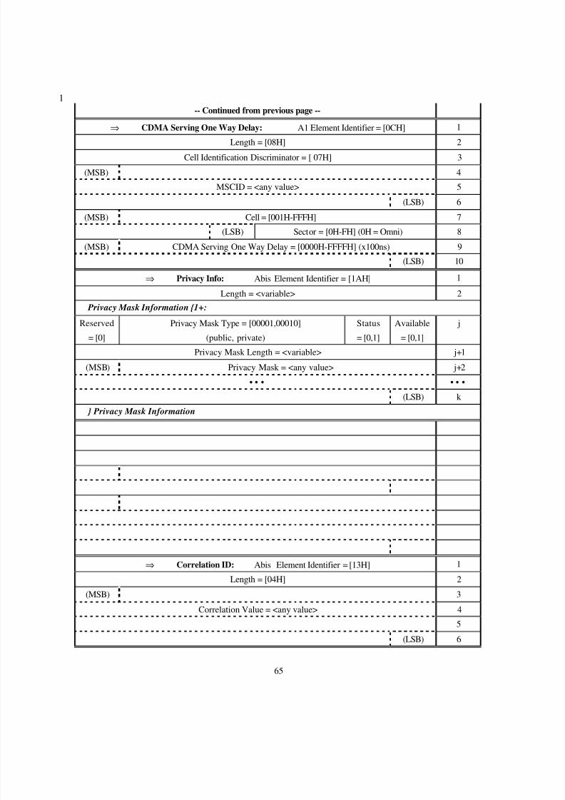
8/2/2019 Abis CDMA2000
http://slidepdf.com/reader/full/abis-cdma2000 68/89
65
1-- Continued from previous page --
⇒ CDMA Serving One Way Delay: A1 Element Identifier = [0CH] 1
Length = [08H] 2
Cell Identification Discriminator = [ 07H] 3
(MSB) 4
MSCID = <any value> 5
(LSB) 6
(MSB) Cell = [001H-FFFH] 7
(LSB) Sector = [0H-FH] (0H = Omni) 8
(MSB) CDMA Serving One Way Delay = [0000H-FFFFH] (x100ns) 9
(LSB) 10
⇒ Privacy Info: Abis Element Identifier = [1AH] 1Length = <variable> 2
Privacy Mask Information {1+:
Reserved
= [0]
Privacy Mask Type = [00001,00010]
(public, private)
Status
= [0,1]
Available
= [0,1]
j
Privacy Mask Length = <variable> j+1
(MSB) Privacy Mask = <any value> j+2
• • • • • •
(LSB) k
} Privacy Mask Information
⇒ Correlation ID: Abis Element Identifier = [13H] 1
Length = [04H] 2
(MSB) 3
Correlation Value = <any value> 4
5
(LSB) 6
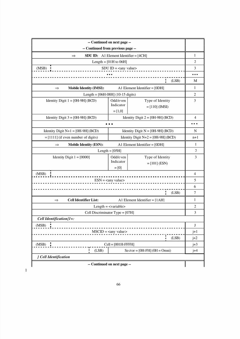
8/2/2019 Abis CDMA2000
http://slidepdf.com/reader/full/abis-cdma2000 69/89
66
-- Continued on next page --
-- Continued from previous page --
⇒ SDU ID: A1 Element Identifier = [4CH] 1
Length = [01H to 06H] 2
(MSB) SDU ID = <any value> 3
• • • • • •
(LSB) M
⇒ Mobile Identity (IMSI): A1 Element Identifier = [0DH] 1
Length = [06H-08H] (10-15 digits) 2
Identity Digit 1 = [0H-9H] (BCD) Odd/evenIndicator
= [1,0]
Type of Identity
= [110] (IMSI)
3
Identity Digit 3 = [0H-9H] (BCD) Identity Digit 2 = [0H-9H] (BCD) 4• • • • • •
Identity Digit N+1 = [0H-9H] (BCD) Identity Digit N = [0H-9H] (BCD) N
= [1111] (if even number of digits) Identity Digit N+2 = [0H-9H] (BCD) n+1
⇒ Mobile Identity (ESN): A1 Element Identifier = [0DH] 1
Length = [05H] 2
Identity Digit 1 = [0000] Odd/evenIndicator
= [0]
Type of Identity
= [101] (ESN)
3
(MSB) 4
ESN = <any value> 5
6
(LSB) 7
⇒ Cell Identifier List: A1 Element Identifier = [1AH] 1
Length = <variable> 2
Cell Discriminator Type = [07H] 3
Cell Identification{1+:
(MSB) J
MSCID = <any value> j+1
(LSB) j+2(MSB) Cell = [001H-FFFH] j+3
(LSB) Sector = [0H-FH] (0H = Omni) j+4
} Cell Identification
-- Continued on next page --
1
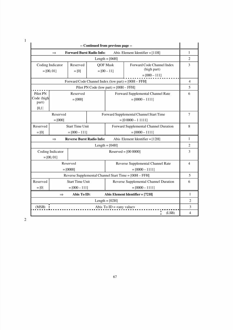
8/2/2019 Abis CDMA2000
http://slidepdf.com/reader/full/abis-cdma2000 70/89
67
1-- Continued from previous page --
⇒ Forward Burst Radio Info: Abis Element Identifier = [11H] 1
Length = [06H] 2
Coding Indicator
= [00, 01]
Reserved
= [0]
QOF Mask
= [00 – 11]
Forward Code Channel Index(high part)
= [000 – 111]
3
Forward Code Channel Index (low part) = [00H – FFH] 4
Pilot PN Code (low part) = [00H – FFH] 5
Pilot PNCode (high
part)
[0,1]
Reserved
= [000]
Forward Supplemental Channel Rate
= [0000 – 1111]
6
Reserved= [000]
Forward Supplemental Channel Start Time= [0 0000 – 1 1111]
7
Reserved
= [0]
Start Time Unit
= [000 – 111]
Forward Supplemental Channel Duration
= [0000 – 1111]
8
⇒ Reverse Burst Radio Info: Abis Element Identifier = [12H] 1
Length = [04H] 2
Coding Indicator
= [00, 01]
Reserved = [00 0000] 3
Reserved
= [0000]
Reverse Supplemental Channel Rate
= [0000 – 1111]
4
Reverse Supplemental Channel Start Time = [00H – FFH] 5
Reserved
= [0]
Start Time Unit
= [000 – 111]
Reverse Supplemental Channel Duration
= [0000 – 1111]
6
⇒ Abis To ID: Abis Element Identifier = [72H] 1
Length = [02H] 2
(MSB) Abis To ID = <any value> 3
(LSB) 4
2
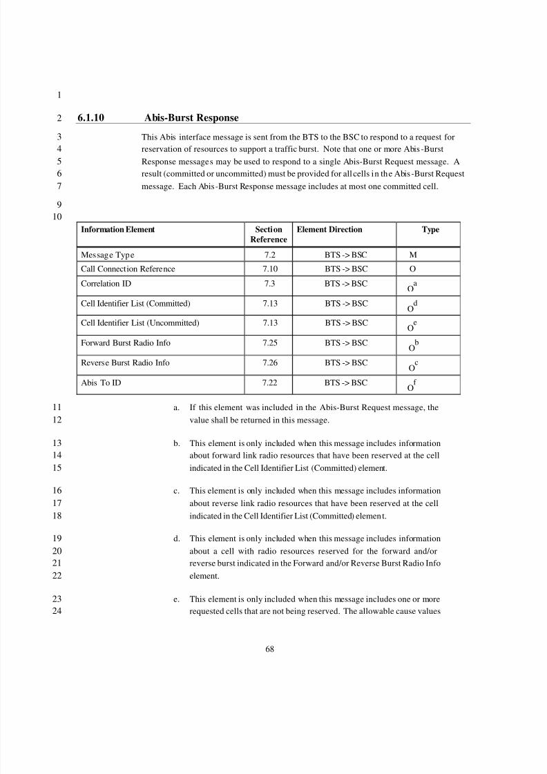
8/2/2019 Abis CDMA2000
http://slidepdf.com/reader/full/abis-cdma2000 71/89
68
1
6.1.10 Abis-Burst Response2
This Abis interface message is sent from the BTS to the BSC to respond to a request for3reservation of resources to support a traffic burst. Note that one or more Abis -Burst4Response messages may be used to respond to a single Abis-Burst Request message. A5result (committed or uncommitted) must be provided for all cells in the Abis -Burst Request6message. Each Abis-Burst Response message includes at most one committed cell.7
910
Information Element SectionReference
Element Direction Type
Message Type 7.2 BTS -> BSC M
Call Connection Reference 7.10 BTS -> BSC OCorrelation ID 7.3 BTS -> BSC
Oa
Cell Identifier List (Committed) 7.13 BTS -> BSCO
d
Cell Identifier List (Uncommitted) 7.13 BTS -> BSCO
e
Forward Burst Radio Info 7.25 BTS -> BSCO
b
Reverse Burst Radio Info 7.26 BTS -> BSCO
c
Abis To ID 7.22 BTS -> BSCO
f
a. If this element was included in the Abis-Burst Request message, the11value shall be returned in this message.12
b. This element is only included when this message includes information13about forward link radio resources that have been reserved at the cell14indicated in the Cell Identifier List (Committed) element.15
c. This element is only included when this message includes information16about reverse link radio resources that have been reserved at the cell17indicated in the Cell Identifier List (Committed) elemen t.18
d. This element is only included when this message includes information19 about a cell with radio resources reserved for the forward and/or20reverse burst indicated in the Forward and/or Reverse Burst Radio Info21element.22
e. This element is only included when this message includes one or more23requested cells that are not being reserved. The allowable cause values24
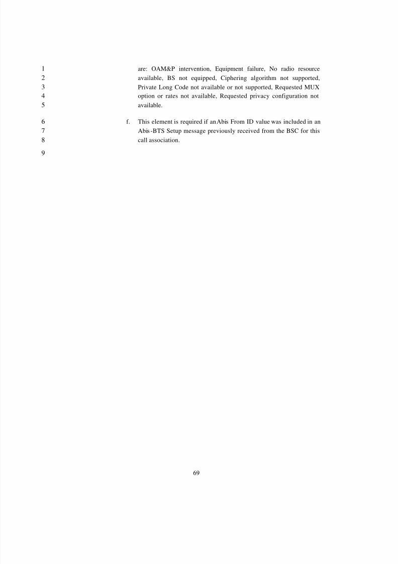
8/2/2019 Abis CDMA2000
http://slidepdf.com/reader/full/abis-cdma2000 72/89
69
are: OAM&P intervention, Equipment failure, No radio resource1available, BS not equipped, Ciphering algorithm not supported,2Private Long Code not available or not supported, Requested MUX3
option or rates not available, Requested privacy configuration not4 available.5
f. This element is required if an Abis From ID value was included in an6Abis -BTS Setup message previously received from the BSC for this7call association.8
9
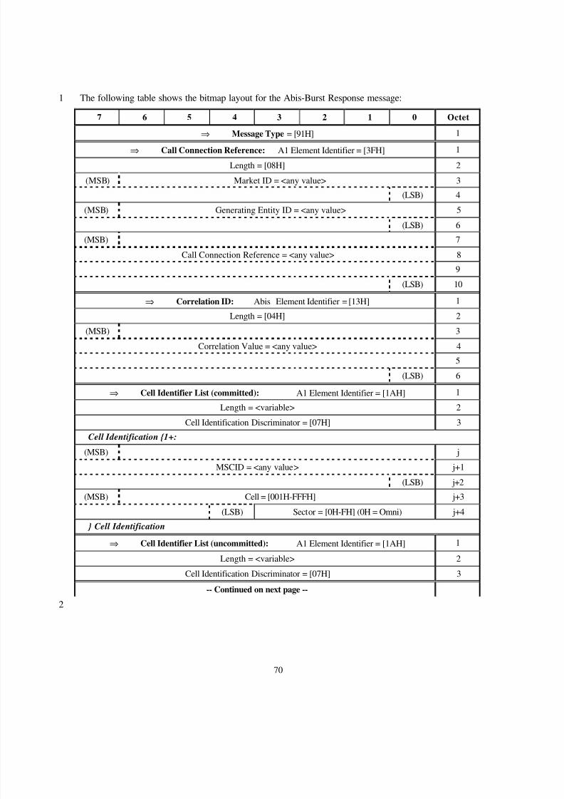
8/2/2019 Abis CDMA2000
http://slidepdf.com/reader/full/abis-cdma2000 73/89
70
The following table shows the bitmap layout for the Abis-Burst Response message:1
7 6 5 4 3 2 1 0 Octet
⇒ Message Type = [91H] 1
⇒ Call Connection Reference: A1 Element Identifier = [3FH] 1
Length = [08H] 2
(MSB) Market ID = <any value> 3
(LSB) 4
(MSB) Generating Entity ID = <any value> 5
(LSB) 6
(MSB) 7
Call Connection Reference = <any value> 8
9
(LSB) 10
⇒ Correlation ID: Abis Element Identifier = [13H] 1
Length = [04H] 2
(MSB) 3
Correlation Value = <any value> 4
5
(LSB) 6
⇒ Cell Identifier List (committed): A1 Element Identifier = [1AH] 1
Length = <variable> 2
Cell Identification Discriminator = [07H] 3
Cell Identification {1+:
(MSB) j
MSCID = <any value> j+1
(LSB) j+2
(MSB) Cell = [001H-FFFH] j+3
(LSB) Sector = [0H-FH] (0H = Omni) j+4
} Cell Identification
⇒ Cell Identifier List (uncommitted): A1 Element Identifier = [1AH] 1
Length = <variable> 2Cell Identification Discriminator = [07H] 3
-- Continued on next page --
2
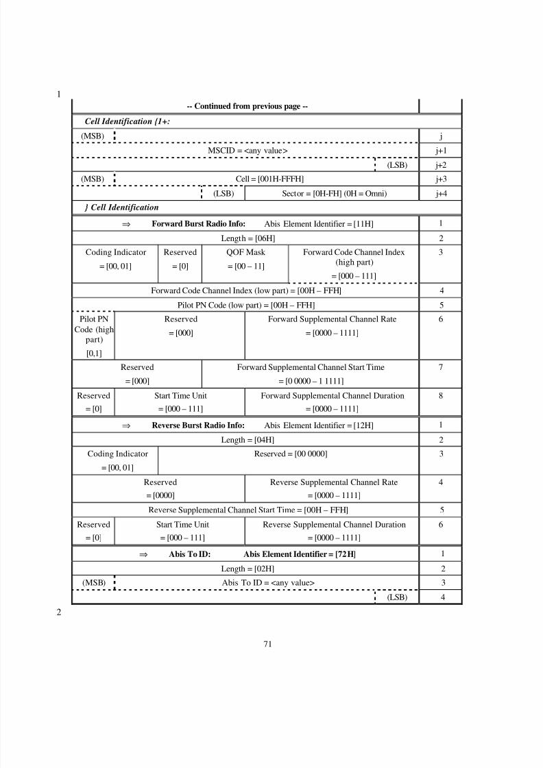
8/2/2019 Abis CDMA2000
http://slidepdf.com/reader/full/abis-cdma2000 74/89
71
1-- Continued from previous page --
Cell Identification {1+:
(MSB) j
MSCID = <any value> j+1
(LSB) j+2
(MSB) Cell = [001H-FFFH] j+3
(LSB) Sector = [0H-FH] (0H = Omni) j+4
} Cell Identification
⇒ Forward Burst Radio Info: Abis Element Identifier = [11H] 1
Length = [06H] 2
Coding Indicator
= [00, 01]
Reserved
= [0]
QOF Mask
= [00 – 11]
Forward Code Channel Index(high part)
= [000 – 111]
3
Forward Code Channel Index (low part) = [00H – FFH] 4
Pilot PN Code (low part) = [00H – FFH] 5
Pilot PNCode (high
part)
[0,1]
Reserved
= [000]
Forward Supplemental Channel Rate
= [0000 – 1111]
6
Reserved
= [000]
Forward Supplemental Channel Start Time
= [0 0000 – 1 1111]
7
Reserved
= [0]
Start Time Unit
= [000 – 111]
Forward Supplemental Channel Duration
= [0000 – 1111]
8
⇒ Reverse Burst Radio Info: Abis Element Identifier = [12H] 1
Length = [04H] 2
Coding Indicator
= [00, 01]
Reserved = [00 0000] 3
Reserved
= [0000]
Reverse Supplemental Channel Rate
= [0000 – 1111]
4
Reverse Supplemental Channel Start Time = [00H – FFH] 5
Reserved
= [0]
Start Time Unit
= [000 – 111]
Reverse Supplemental Channel Duration
= [0000 – 1111]
6
⇒ Abis To ID: Abis Element Identifier = [72H] 1
Length = [02H] 2
(MSB) Abis To ID = <any value> 3
(LSB) 4
2
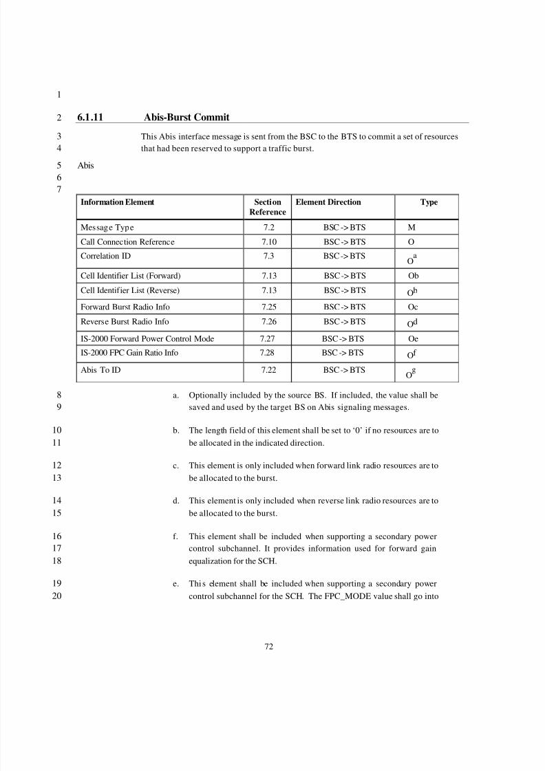
8/2/2019 Abis CDMA2000
http://slidepdf.com/reader/full/abis-cdma2000 75/89
72
1
6.1.11 Abis-Burst Commit2
This Abis interface message is sent from the BSC to the BTS to commit a set of resources3that had been reserved to support a traffic burst.4
Abis567
Information Element SectionReference
Element Direction Type
Message Type 7.2 BSC -> BTS M
Call Connection Reference 7.10 BSC -> BTS O
Correlation ID 7.3 BSC -> BTSO
a
Cell Identifier List (Forward) 7.13 BSC -> BTS Ob
Cell Identifier List (Reverse) 7.13 BSC -> BTS Ob
Forward Burst Radio Info 7.25 BSC -> BTS Oc
Reverse Burst Radio Info 7.26 BSC -> BTS Od
IS-2000 Forward Power Control Mode 7.27 BSC -> BTS Oe
IS-2000 FPC Gain Ratio Info 7.28 BSC -> BTS Of
Abis To ID 7.22 BSC -> BTSO
g
a. Optionally included by the source BS. If included, the value shall be8saved and used by the target BS on Abis signaling messages.9
b. The length field of this element shall be set to ‘0’ if no resources are to10be allocated in the indicated direction.11
c. This element is only included when forward link radio resources are to12be allocated to the burst.13
d. This element is only included when reverse link radio resources are to14be allocated to the burst.15
f. This element shall be included when supporting a secondary power16 control subchannel. It provides information used for forward gain17equalization for the SCH.18
e. Thi s element shall be included when supporting a secondary power19control subchannel for the SCH. The FPC_MODE value shall go into20
8/2/2019 Abis CDMA2000
http://slidepdf.com/reader/full/abis-cdma2000 76/89
73
effect at the earlier of the burst start times indicated in the Forward1Burst Radio Info and/or Reverse Burst Radio Info element.2
g. This element is required if an Abis From ID value was included in an3Abis BTS Setup Ack message previously received from the BS for this4call association.5
6
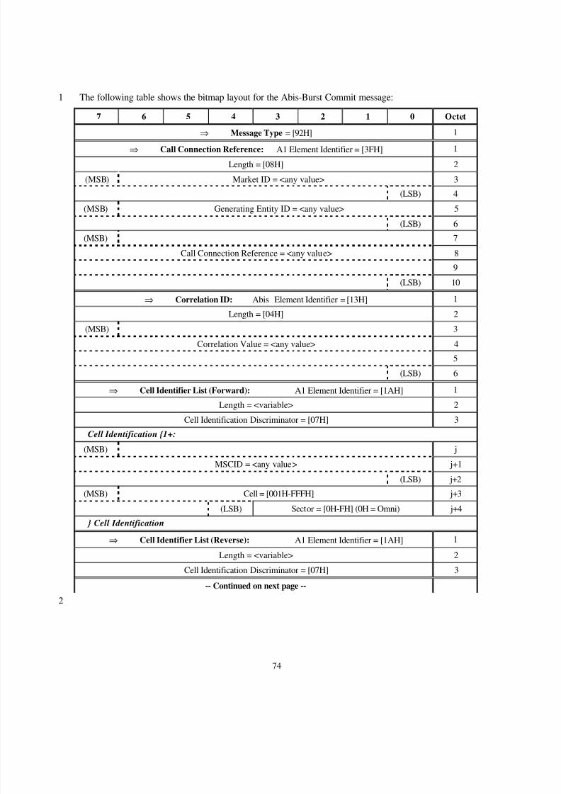
8/2/2019 Abis CDMA2000
http://slidepdf.com/reader/full/abis-cdma2000 77/89
74
The following table shows the bitmap layout for the Abis-Burst Commit message:1
7 6 5 4 3 2 1 0 Octet
⇒ Message Type = [92H] 1
⇒ Call Connection Reference: A1 Element Identifier = [3FH] 1
Length = [08H] 2
(MSB) Market ID = <any value> 3
(LSB) 4
(MSB) Generating Entity ID = <any value> 5
(LSB) 6
(MSB) 7
Call Connection Reference = <any value> 8
9
(LSB) 10
⇒ Correlation ID: Abis Element Identifier = [13H] 1
Length = [04H] 2
(MSB) 3
Correlation Value = <any value> 4
5
(LSB) 6
⇒ Cell Identifier List (Forward): A1 Element Identifier = [1AH] 1
Length = <variable> 2
Cell Identification Discriminator = [07H] 3
Cell Identification {1+:
(MSB) j
MSCID = <any value> j+1
(LSB) j+2
(MSB) Cell = [001H-FFFH] j+3
(LSB) Sector = [0H-FH] (0H = Omni) j+4
} Cell Identification
⇒ Cell Identifier List (Reverse): A1 Element Identifier = [1AH] 1
Length = <variable> 2Cell Identification Discriminator = [07H] 3
-- Continued on next page --
2
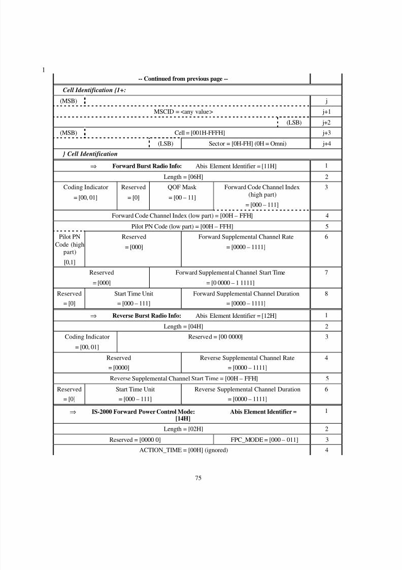
8/2/2019 Abis CDMA2000
http://slidepdf.com/reader/full/abis-cdma2000 78/89
75
1-- Continued from previous page --
Cell Identification {1+:
(MSB) j
MSCID = <any value> j+1
(LSB) j+2
(MSB) Cell = [001H-FFFH] j+3
(LSB) Sector = [0H-FH] (0H = Omni) j+4
} Cell Identification
⇒ Forward Burst Radio Info: Abis Element Identifier = [11H] 1
Length = [06H] 2
Coding Indicator
= [00, 01]
Reserved
= [0]
QOF Mask
= [00 – 11]
Forward Code Channel Index(high part)
= [000 – 111]
3
Forward Code Channel Index (low part) = [00H – FFH] 4
Pilot PN Code (low part) = [00H – FFH] 5
Pilot PNCode (high
part)
[0,1]
Reserved
= [000]
Forward Supplemental Channel Rate
= [0000 – 1111]
6
Reserved
= [000]
Forward Supplemental Channel Start Time
= [0 0000 – 1 1111]
7
Reserved
= [0]
Start Time Unit
= [000 – 111]
Forward Supplemental Channel Duration
= [0000 – 1111]
8
⇒ Reverse Burst Radio Info: Abis Element Identifier = [12H] 1
Length = [04H] 2
Coding Indicator
= [00, 01]
Reserved = [00 0000] 3
Reserved
= [0000]
Reverse Supplemental Channel Rate
= [0000 – 1111]
4
Reverse Supplemental Channel Start Time = [00H – FFH] 5
Reserved
= [0]
Start Time Unit
= [000 – 111]
Reverse Supplemental Channel Duration
= [0000 – 1111]
6
⇒ IS-2000 Forward Power Control Mode: Abis Element Identifier =[14H]
1
Length = [02H] 2
Reserved = [0000 0] FPC_MODE = [000 – 011] 3
ACTION_TIME = [00H] (ignored) 4
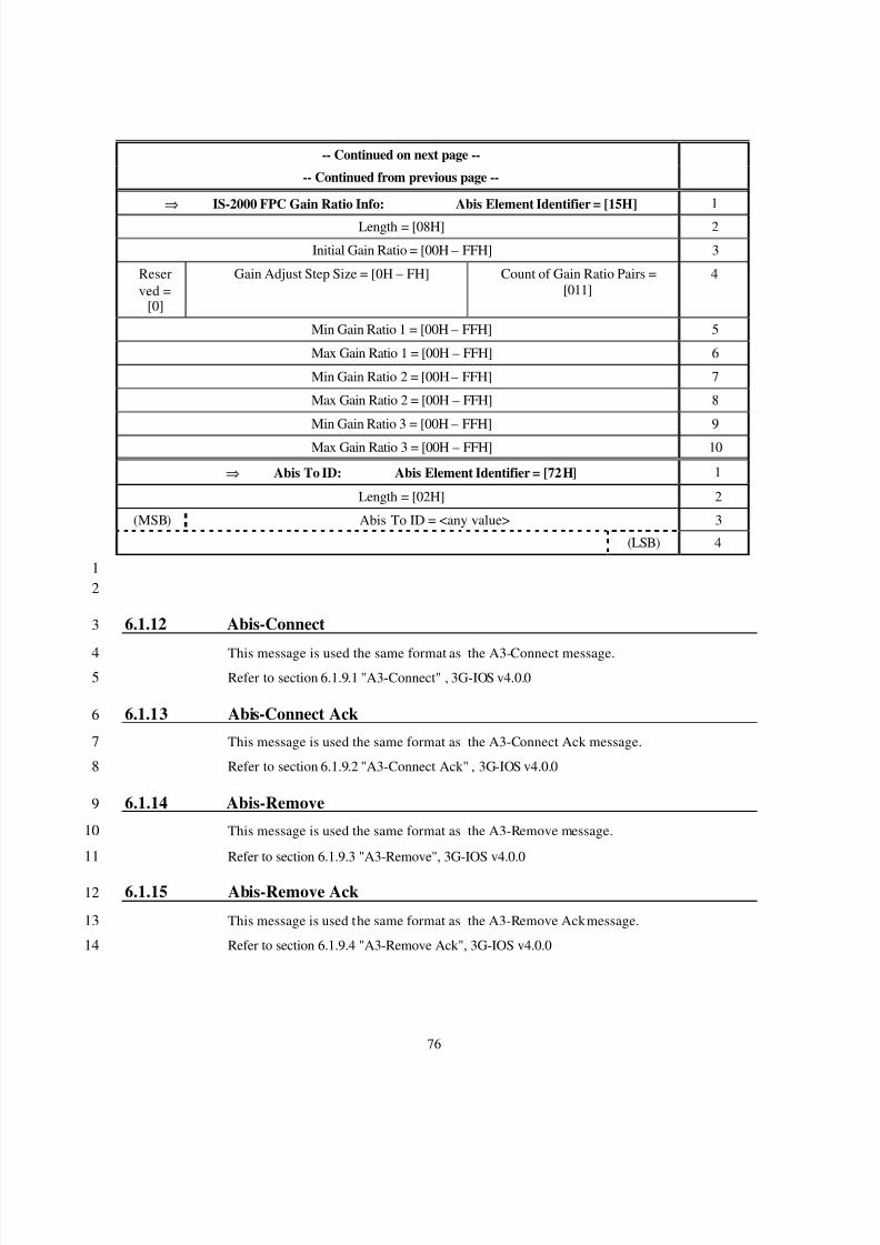
8/2/2019 Abis CDMA2000
http://slidepdf.com/reader/full/abis-cdma2000 79/89
76
-- Continued on next page --
-- Continued from previous page --
⇒ IS-2000 FPC Gain Ratio Info: Abis Element Identifier = [15H] 1
Length = [08H] 2
Initial Gain Ratio = [00H – FFH] 3
Reserved =
[0]
Gain Adjust Step Size = [0H – FH] Count of Gain Ratio Pairs =[011]
4
Min Gain Ratio 1 = [00H – FFH] 5
Max Gain Ratio 1 = [00H – FFH] 6
Min Gain Ratio 2 = [00H – FFH] 7
Max Gain Ratio 2 = [00H – FFH] 8
Min Gain Ratio 3 = [00H – FFH] 9
Max Gain Ratio 3 = [00H – FFH] 10
⇒ Abis To ID: Abis Element Identifier = [72H] 1
Length = [02H] 2
(MSB) Abis To ID = <any value> 3
(LSB) 4
12
6.1.12 Abis-Connect3
This message is used the same format as the A3-Connect message.4Refer to section 6.1.9.1 "A3-Connect" , 3G-IOS v4.0.05
6.1.13 Abis-Connect Ack6
This message is used the same format as the A3-Connect Ack message.7
Refer to section 6.1.9.2 "A3-Connect Ack" , 3G-IOS v4.0.08
6.1.14 Abis-Remove9
This message is used the same format as the A3-Remove message.10
Refer to section 6.1.9.3 "A3-Remove", 3G-IOS v4.0.011
6.1.15 Abis-Remove Ack12
This message is used the same format as the A3-Remove Ack message.13
Refer to section 6.1.9.4 "A3-Remove Ack", 3G-IOS v4.0.014
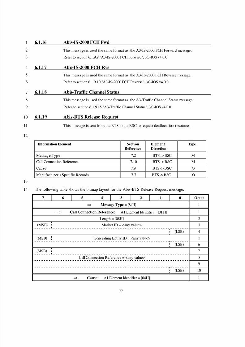
8/2/2019 Abis CDMA2000
http://slidepdf.com/reader/full/abis-cdma2000 80/89
77
6.1.16 Abis-IS-2000 FCH Fwd1
This message is used the same format as the A3-IS-2000 FCH Forward message.2
Refer to section 6.1.9.9 "A3-IS-2000 FCH Forward", 3G-IOS v4.0.03
6.1.17 Abis-IS-2000 FCH Rvs4
This message is used the same format as the A3-IS-2000 FCH Reverse message.5
Refer to section 6.1.9.10 "A3-IS-2000 FCH Reverse", 3G-IOS v4.0.06
6.1.18 Abis-Traffic Channel Status7
This message is used the same format as the A3-Traffic Channel Status message.8
Refer to section 6.1.9.15 "A3-Traffic Channel Status", 3G-IOS v4.0.09
6.1.19 Abis-BTS Release Request10
This message is sent from the BTS to the BSC to request deallocation resources..11
12
Information Element SectionReference
ElementDirection
Type
Message Type 7.2 BTS -> BSC M
Call Connection Reference 7.10 BTS -> BSC M
Cause 7.9 BTS -> BSC O
Manufacturer’s Specific Records 7.7 BTS -> BSC O
13The following table shows the bitmap layout for the Abis-BTS Release Request message:14
7 6 5 4 3 2 1 0 Octet
⇒ Message Type = [84H] 1
⇒ Call Connection Reference: A1 Element Identifier = [3FH] 1
Length = [08H] 2
(MSB) Market ID = <any value> 3
(LSB) 4
(MSB) Generating Entity ID = <any value> 5
(LSB) 6
(MSB) 7
Call Connection Reference = <any value> 8
9
(LSB) 10
⇒ Cause: A1 Element Identifier = [04H] 1
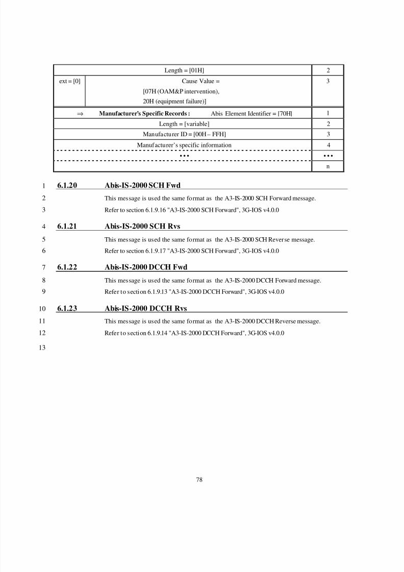
8/2/2019 Abis CDMA2000
http://slidepdf.com/reader/full/abis-cdma2000 81/89
78
Length = [01H] 2
ext = [0] Cause Value =
[07H (OAM&P intervention),
20H (equipment failure)]
3
⇒ Manufacturer’s Specific Records : Abis Element Identifier = [70H] 1
Length = [variable] 2
Manufacturer ID = [00H – FFH] 3
Manufacturer’s specific information 4
• • • • • •
n
6.1.20 Abis-IS-2000 SCH Fwd1
This message is used the same format as the A3-IS-2000 SCH Forward message.2Refer to section 6.1.9.16 "A3-IS-2000 SCH Forward", 3G-IOS v4.0.03
6.1.21 Abis-IS-2000 SCH Rvs4
This message is used the same format as the A3-IS-2000 SCH Reverse message.5
Refer to section 6.1.9.17 "A3-IS-2000 SCH Forward", 3G-IOS v4.0.06
6.1.22 Abis-IS-2000 DCCH Fwd7
This message is used the same format as the A3-IS-2000 DCCH Forward message.8
Refer to section 6.1.9.13 "A3-IS-2000 DCCH Forward", 3G-IOS v4.0.09
6.1.23 Abis-IS-2000 DCCH Rvs10
This message is used the same format as the A3-IS-2000 DCCH Reverse message.11
Refer to section 6.1.9.14 "A3-IS-2000 DCCH Forward", 3G-IOS v4.0.012
13
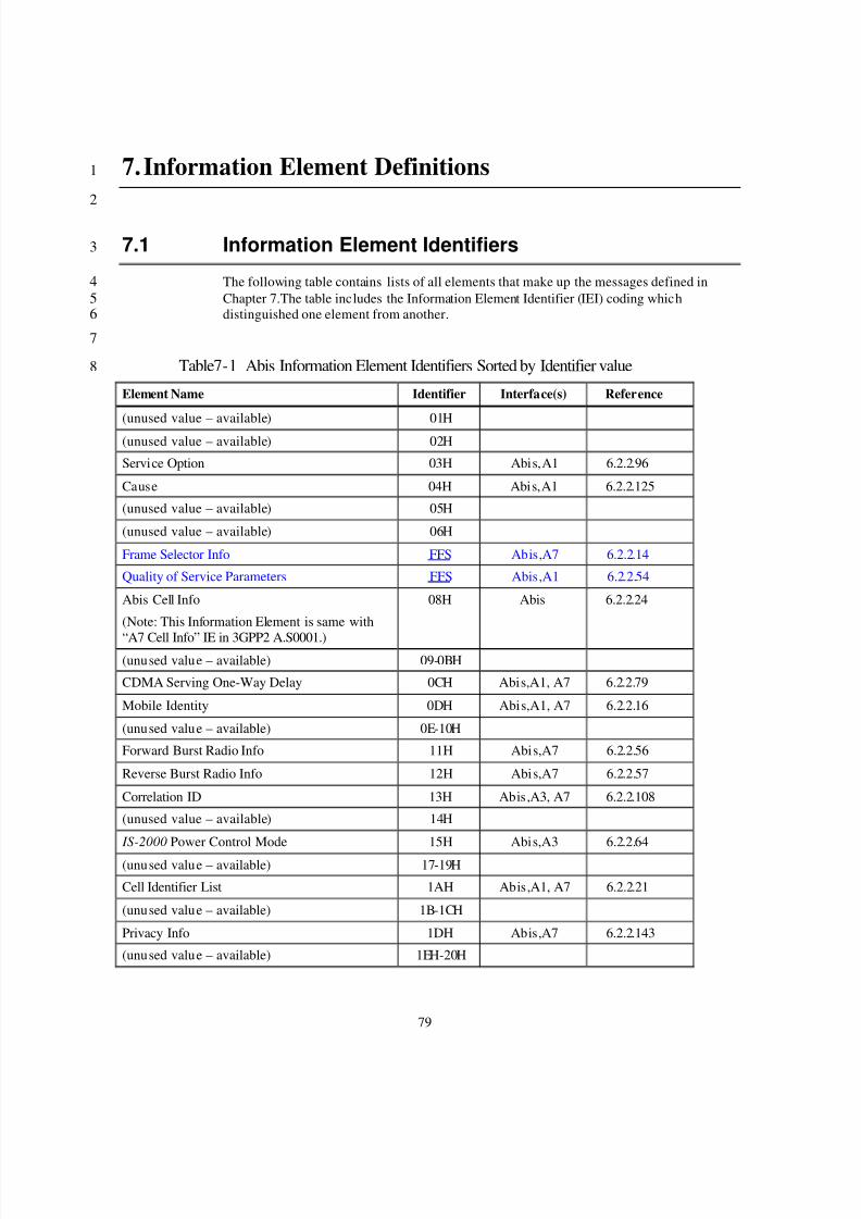
8/2/2019 Abis CDMA2000
http://slidepdf.com/reader/full/abis-cdma2000 82/89
79
7. Information Element Definitions1
2
7.1 Information Element Identifiers3
The following table contains lists of all elements that make up the messages defined in4Chapter 7.The table includes the Information Element Identifier (IEI) coding which5distinguished one element from another.6
7
Table7-1 Abis Information Element Identifiers Sorted by Identifier value8
Element Name Identifier Interface(s) Reference
(unused value – available) 01H
(unused value – available) 02H
Service Option 03H Abis,A1 6.2.2.96
Cause 04H Abis,A1 6.2.2.125
(unused value – available) 05H
(unused value – available) 06H
Frame Selector Info FFS Abis,A7 6.2.2.14
Quality of Service Parameters FFS Abis,A1 6.2.2.54
Abis Cell Info
(Note: This Information Element is same with
“A7 Cell Info” IE in 3GPP2 A.S0001.)
08H Abis 6.2.2.24
(unused value – available) 09-0BH
CDMA Serving One-Way Delay 0CH Abis,A1, A7 6.2.2.79
Mobile Identity 0DH Abis,A1, A7 6.2.2.16
(unused value – available) 0E-10H
Forward Burst Radio Info 11H Abis,A7 6.2.2.56
Reverse Burst Radio Info 12H Abis,A7 6.2.2.57
Correlation ID 13H Abis,A3, A7 6.2.2.108
(unused value – available) 14H
IS-2000 Power Control Mode 15H Abis,A3 6.2.2.64
(unused value – available) 17-19H
Cell Identifier List 1AH Abis,A1, A7 6.2.2.21
(unused value – available) 1B-1CH
Privacy Info 1DH Abis,A7 6.2.2.143
(unused value – available) 1EH-20H
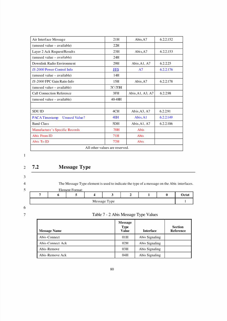
8/2/2019 Abis CDMA2000
http://slidepdf.com/reader/full/abis-cdma2000 83/89
80
Air Interface Message 21H Abis,A7 6.2.2.152
(unused value – available) 22H
Layer 2 Ack Request/Results 23H Abis,A7 6.2.2.153
(unused value – available) 24H
Downlink Radio Environment 29H Abis,A1, A7 6.2.2.25
IS-2000 Power Control Info FFS A7 6.2.2.176
(unused value – available) 14H
IS-2000 FPC Gain Ratio Info 15H Abis,A7 6.2.2.178
(unused value – available) 2C-2DH
Call Connection Reference 3FH Abis,A1, A3, A7 6.2.2.98
(unused value – available) 40-48H
SDU ID 4CH Abis,A3, A7 6.2.2.91PACA Timestamp Unused Value? 4EH Abis,A1 6.2.2.149
Band Class 5DH Abis,A1, A7 6.2.2.106
Manufacture’s Specific Records 70H Abis
Abis From ID 71H Abis
Abis To ID 72H Abis
All other values are reserved.
1
7.2 Message Type2
3
The Message Type element is used to indicate the type of a message on the Abis interfaces.4
Element Format:57 6 5 4 3 2 1 0 Octet
Message Type 1
6
Table 7 - 2 Abis Message Type Values7
Message Name
MessageTypeValue Interface
SectionReference
Abis-Connect 01H Abis Signaling
Abis-Connect Ack 02H Abis Signaling
Abis-Remove 03H Abis Signaling
Abis-Remove Ack 04H Abis Signaling
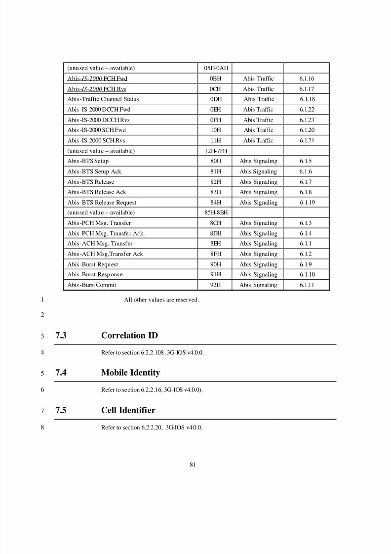
8/2/2019 Abis CDMA2000
http://slidepdf.com/reader/full/abis-cdma2000 84/89
81
(unused value – available) 05H-0AH
Abis- IS-2000 FCH Fwd 0BH Abis Traffic 6.1.16
Abis- IS-2000 FCH Rvs 0CH Abis Traffic 6.1.17
Abis-Traffic Channel Status 0DH Abis Traffic 6.1.18
Abis -IS-2000 DCCH Fwd 0EH Abis Traffic 6.1.22
Abis -IS-2000 DCCH Rvs 0FH Abis Traffic 6.1.23
Abis -IS-2000 SCH Fwd 10H Abis Traffic 6.1.20
Abis -IS-2000 SCH Rvs 11H Abis Traffic 6.1.21
(unused value – available) 12H-7FH
Abis-BTS Setup 80H Abis Signaling 6.1.5
Abis-BTS Setup Ack 81H Abis Signaling 6.1.6
Abis-BTS Release 82H Abis Signaling 6.1.7
Abis-BTS Release Ack 83H Abis Signaling 6.1.8Abis-BTS Release Request 84H Abis Signaling 6.1.19
(unused value – available) 85H-8BH
Abis-PCH Msg. Transfer 8CH Abis Signaling 6.1.3
Abis-PCH Msg. Transfer Ack 8DH Abis Signaling 6.1.4
Abis-ACH Msg. Transfer 8EH Abis Signaling 6.1.1
Abis-ACH Msg.Transfer Ack 8FH Abis Signaling 6.1.2
Abis-Burst Request 90H Abis Signaling 6.1.9
Abis-Burst Response 91H Abis Signaling 6.1.10
Abis -Burst Commit 92H Abis Signaling 6.1.11
All other values are reserved.1
2
7.3 Correlation ID3
Refer to section 6.2.2.108, 3G-IOS v4.0.0.4
7.4 Mobile Identity5
Refer to section 6.2.2.16, 3G-IOS v4.0.0).6
7.5 Cell Identifier7
Refer to section 6.2.2.20, 3G-IOS v4.0.0.8
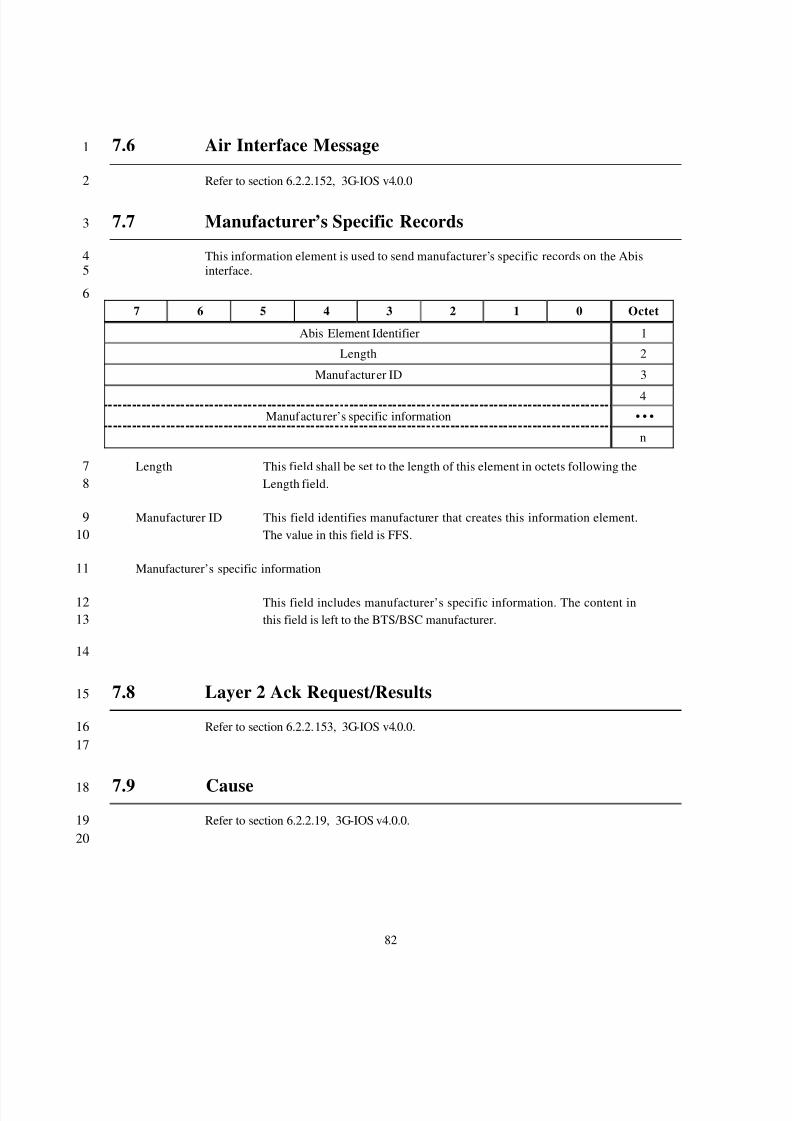
8/2/2019 Abis CDMA2000
http://slidepdf.com/reader/full/abis-cdma2000 85/89
82
7.6 Air Interface Message1
Refer to section 6.2.2.152, 3G-IOS v4.0.02
7.7 Manufacturer’s Specific Records3
This information element is used to send manufacturer’s specific records on the Abis4interface.5
67 6 5 4 3 2 1 0 Octet
Abis Element Identifier 1
Length 2
Manufacturer ID 3
4
Manufacturer’s specific information • • •
n
Length This field shall be set to the length of this element in octets following the7Length field.8
Manufacturer ID This field identifies manufacturer that creates this information element.9The value in this field is FFS.10
Manufacturer’s specific information11
This field includes manufacturer’s specific information. The content in12this field is left to the BTS/BSC manufacturer.13
14
7.8 Layer 2 Ack Request/Results15
Refer to section 6.2.2.153, 3G-IOS v4.0.0.1617
7.9 Cause18
Refer to section 6.2.2.19, 3G-IOS v4.0.0.1920
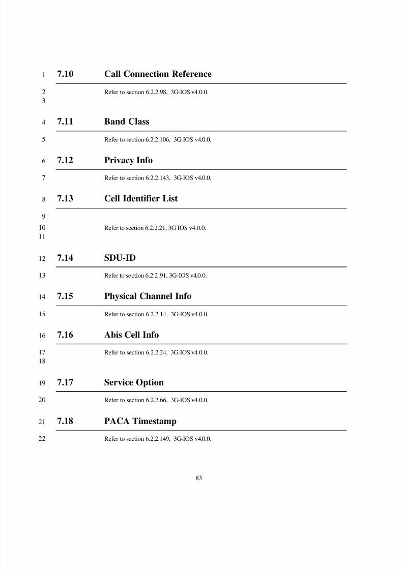
8/2/2019 Abis CDMA2000
http://slidepdf.com/reader/full/abis-cdma2000 86/89
83
7.10 Call Connection Reference1
Refer to section 6.2.2.98, 3G-IOS v4.0.0.2
3
7.11 Band Class4
Refer to section 6.2.2.106, 3G-IOS v4.0.0.5
7.12 Privacy Info6
Refer to section 6.2.2.143, 3G-IOS v4.0.0.7
7.13 Cell Identifier List8
9
Refer to section 6.2.2.21, 3G IOS v4.0.0.1011
7.14 SDU-ID12
Refer to section 6.2.2.91, 3G-IOS v4.0.0.13
7.15 Physical Channel Info14
Refer to section 6.2.2.14, 3G-IOS v4.0.0.15
7.16 Abis Cell Info16
Refer to section 6.2.2.24, 3G-IOS v4.0.0.1718
7.17 Service Option19
Refer to section 6.2.2.66, 3G-IOS v4.0.0.20
7.18 PACA Timestamp21
Refer to section 6.2.2.149, 3G-IOS v4.0.0.22
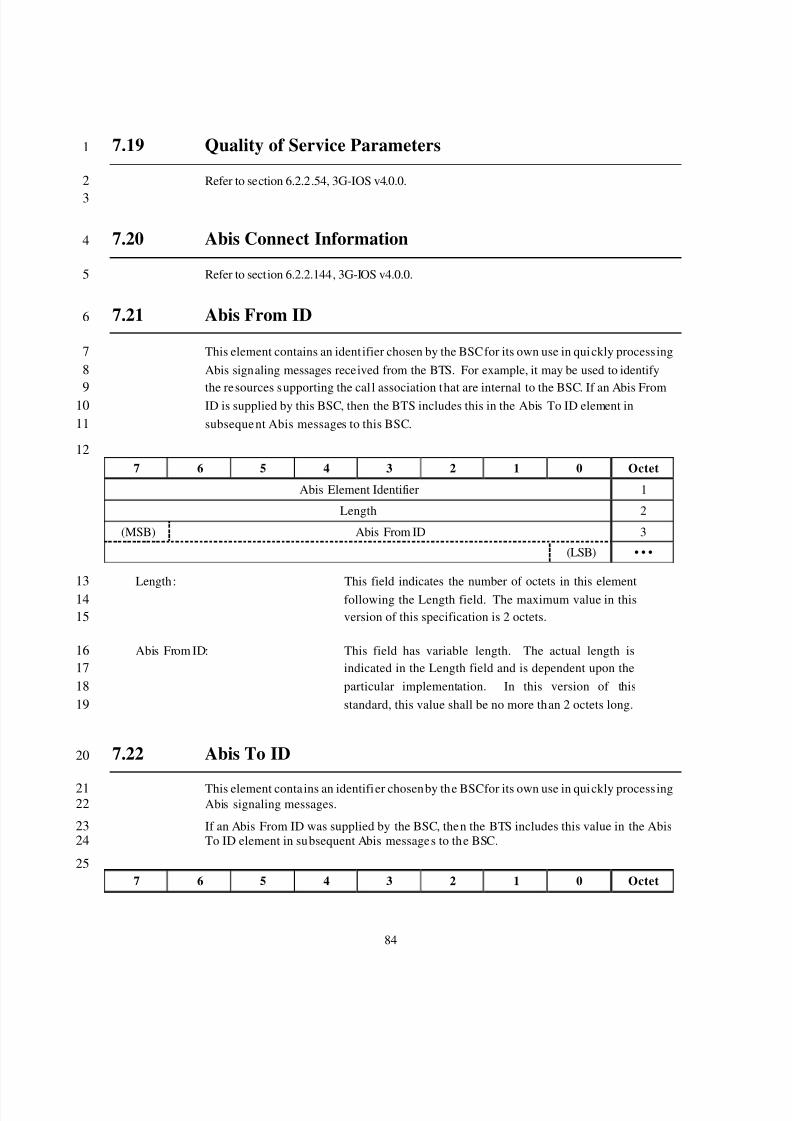
8/2/2019 Abis CDMA2000
http://slidepdf.com/reader/full/abis-cdma2000 87/89
84
7.19 Quality of Service Parameters1
Refer to section 6.2.2.54, 3G-IOS v4.0.0.2
3
7.20 Abis Connect Information4
Refer to section 6.2.2.144, 3G-IOS v4.0.0.5
7.21 Abis From ID6
This element contains an ident ifier chosen by the BSC for its own use in quickly process ing7Abis signaling messages received from the BTS. For example, it may be used to identify8
the resources supporting the cal l association that are internal to the BSC. If an Abis From9ID is supplied by this BSC, then the BTS includes this in the Abis To ID element in10subsequent Abis messages to this BSC.11
127 6 5 4 3 2 1 0 Octet
Abis Element Identifier 1
Length 2
(MSB) Abis From ID 3
(LSB) • • •
Length: This field indicates the number of octets in this element13following the Length field. The maximum value in this14version of this specification is 2 octets.15
Abis From ID: This field has variable length. The actual length is16indicated in the Length field and is dependent upon the17particular implementation. In this version of this18standard, this value shall be no more than 2 octets long.19
7.22 Abis To ID20
This element conta ins an identifier chosen by the BSC for its own use in quickly process ing21Abis signaling messages.22
If an Abis From ID was supplied by the BSC, then the BTS includes this value in the Abis23To ID element in subsequent Abis messages to the BSC.24
257 6 5 4 3 2 1 0 Octet
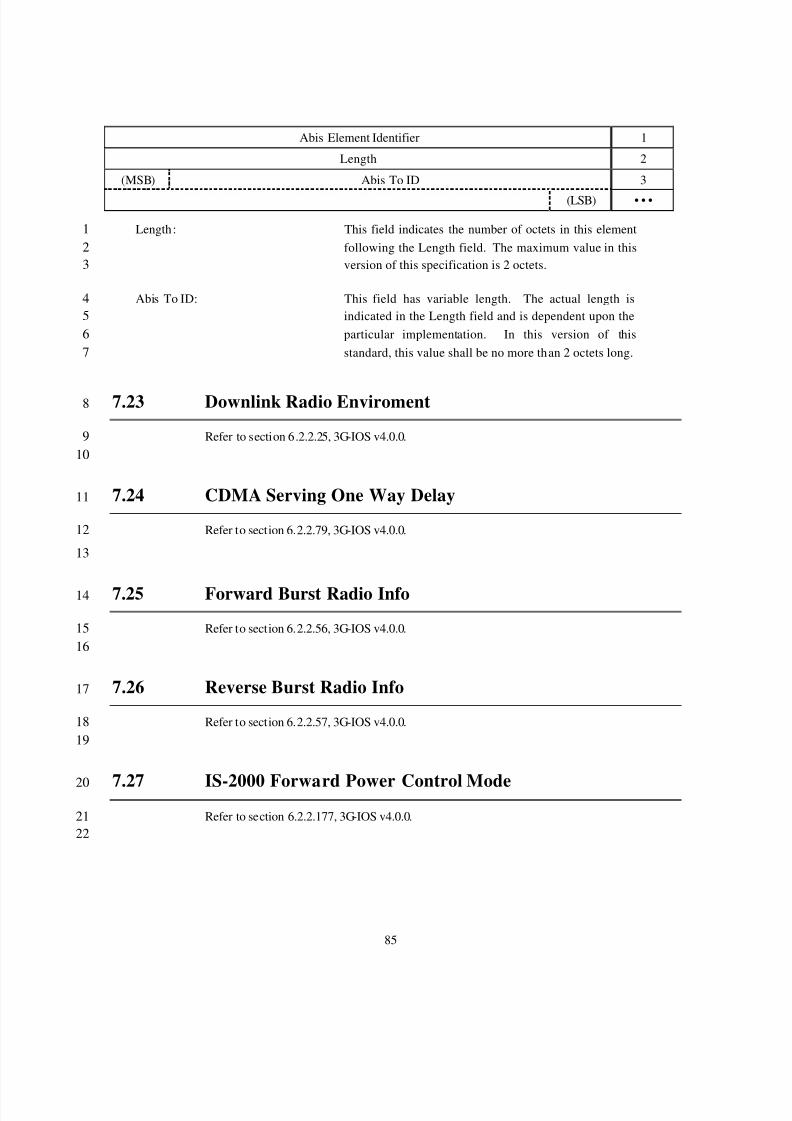
8/2/2019 Abis CDMA2000
http://slidepdf.com/reader/full/abis-cdma2000 88/89
85
Abis Element Identifier 1
Length 2
(MSB) Abis To ID 3
(LSB) • • •
Length: This field indicates the number of octets in this element1following the Length field. The maximum value in this2version of this specification is 2 octets.3
Abis To ID: This field has variable length. The actual length is4indicated in the Length field and is dependent upon the5particular implementation. In this version of this6standard, this value shall be no more than 2 octets long.7
7.23 Downlink Radio Enviroment8
Refer to section 6.2.2.25, 3G-IOS v4.0.0.910
7.24 CDMA Serving One Way Delay11
Refer to section 6.2.2.79, 3G-IOS v4.0.0.12
13
7.25 Forward Burst Radio Info14
Refer to section 6.2.2.56, 3G-IOS v4.0.0.1516
7.26 Reverse Burst Radio Info17
Refer to section 6.2.2.57, 3G-IOS v4.0.0.1819
7.27 IS-2000 Forward Power Control Mode20
Refer to section 6.2.2.177, 3G-IOS v4.0.0.2122

8/2/2019 Abis CDMA2000
http://slidepdf.com/reader/full/abis-cdma2000 89/89
7.28 IS-2000 FPC Gain Ratio Info1
Refer to section 6.2.2.178, 3G-IOS v4.0.0.2
3
7.29 Cell Identifier List4
Refer to section 6.2.2.21, 3G-IOS v4.0.0.5
6