abb machinery drives - acs850, 0.37 to 560 kw/0.5 to 700 ... · pdf file4 abb machinery drives...
TRANSCRIPT
ABB machinery drivesACS850 0.37 to 560 kW/0.5 to 700 hpCatalog
Low voltage AC drives
2 ABB machinery drives ACS850 | Catalog
Type designation:
Product series
Types and
construction
Ratings
Voltages
Options
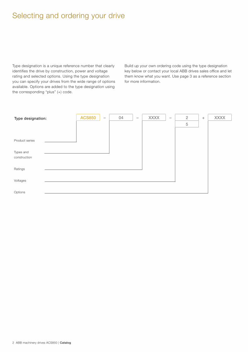
ACS850 – 04 – XXXX – 2 + XXXX
5
Selecting and ordering your drive
Type designation is a unique reference number that clearly identifies the drive by construction, power and voltage rating and selected options. Using the type designation you can specify your drives from the wide range of options available. Options are added to the type designation using the corresponding “plus” (+) code.
Build up your own ordering code using the type designation key below or contact your local ABB drives sales office and let them know what you want. Use page 3 as a reference section for more information.
Catalog | ABB machinery drives ACS850 3
ContentsABB machinery drives, ACS850
Introduction to ACS850 4
Main features 5
Technical data 6
Ratings, types and dimensions 7
Standard control program 9
Standard software features 10
Standard I/O 11
Options 12
Control and communication modules 12
Control panel 13
G frame drive modules 14
EMC filters 15
Mains circuit 16
PC tools 19
Crane control program 20
Synchronous reluctance motor and drive package 21
Remote monitoring and diagnostic tools 22
Expertise at every stage of the value chain 23
Secure uptime throughout the drive life cycle 23
4 ABB machinery drives ACS850 | Catalog
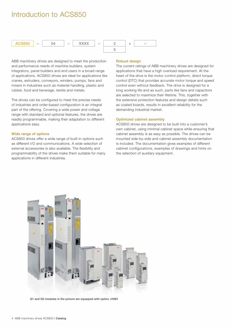
ABB machinery drives are designed to meet the production and performance needs of machine builders, system integrators, panel builders and end users in a broad range of applications. ACS850 drives are ideal for applications like cranes, extruders, conveyors, winders, pumps, fans and mixers in industries such as material handling, plastic and rubber, food and beverage, textile and metals.
The drives can be configured to meet the precise needs of industries and order-based configuration is an integral part of the offering. Covering a wide power and voltage range with standard and optional features, the drives are readily programmable, making their adaptation to different applications easy.
Wide range of optionsACS850 drives offer a wide range of built-in options such as different I/O and communications. A wide selection of external accessories is also available. The flexibility and programmability of the drives make them suitable for many applications in different industries.
Introduction to ACS850
Robust designThe current ratings of ABB machinery drives are designed for applications that have a high overload requirement. At the heart of the drive is the motor control platform, direct torque control (DTC) that provides accurate motor torque and speed control even without feedback. The drive is designed for a long working life and as such, parts like fans and capacitors are selected to maximize their lifetime. This, together with the extensive protection features and design details such as coated boards, results in excellent reliability for the demanding industrial market.
Optimized cabinet assemblyACS850 drives are designed to be built into a customer’s own cabinet, using minimal cabinet space while ensuring that cabinet assembly is as easy as possible. The drives can be mounted side-by-side and cabinet assembly documentation is included. The documentation gives examples of different cabinet configurations, examples of drawings and hints on the selection of auxiliary equipment.
ACS850 – 04 – XXXX – 2 + –
5
G1 and G2 modules in the picture are equipped with option +H381
Catalog | ABB machinery drives ACS850 5
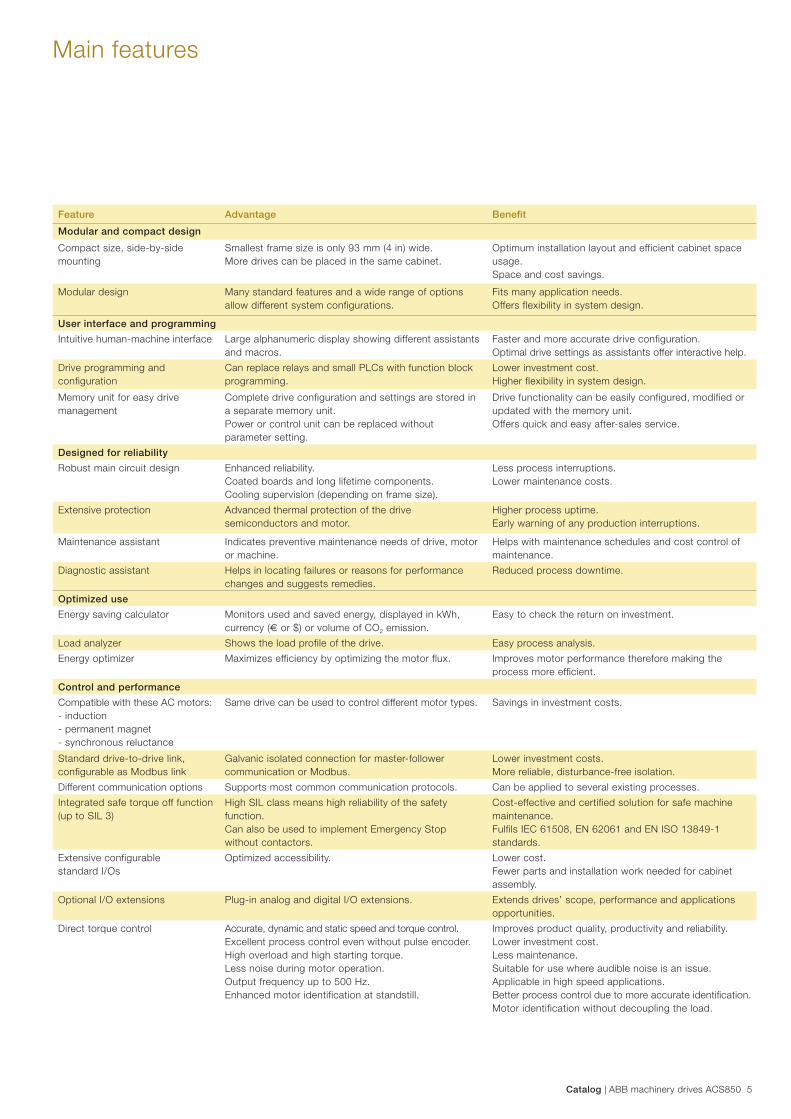
Feature Advantage Benefi t
Modular and compact design
Compact size, side-by-side mounting
Smallest frame size is only 93 mm (4 in) wide.More drives can be placed in the same cabinet.
Optimum installation layout and efficient cabinet space usage.Space and cost savings.
Modular design Many standard features and a wide range of options allow different system configurations.
Fits many application needs.Offers flexibility in system design.
User interface and programming
Intuitive human-machine interface Large alphanumeric display showing different assistants and macros.
Faster and more accurate drive configuration.Optimal drive settings as assistants offer interactive help.
Drive programming and configuration
Can replace relays and small PLCs with function block programming.
Lower investment cost.Higher flexibility in system design.
Memory unit for easy drive management
Complete drive configuration and settings are stored in a separate memory unit.Power or control unit can be replaced without parameter setting.
Drive functionality can be easily configured, modified or updated with the memory unit. Offers quick and easy after-sales service.
Designed for reliability
Robust main circuit design Enhanced reliability.Coated boards and long lifetime components.Cooling supervision (depending on frame size).
Less process interruptions.Lower maintenance costs.
Extensive protection Advanced thermal protection of the drive semiconductors and motor.
Higher process uptime.Early warning of any production interruptions.
Maintenance assistant Indicates preventive maintenance needs of drive, motor or machine.
Helps with maintenance schedules and cost control of maintenance.
Diagnostic assistant Helps in locating failures or reasons for performance changes and suggests remedies.
Reduced process downtime.
Optimized use
Energy saving calculator Monitors used and saved energy, displayed in kWh, currency (€ or $) or volume of CO2 emission.
Easy to check the return on investment.
Load analyzer Shows the load profile of the drive. Easy process analysis.
Energy optimizer Maximizes efficiency by optimizing the motor flux. Improves motor performance therefore making the process more efficient.
Control and performance
Compatible with these AC motors:- induction- permanent magnet- synchronous reluctance
Same drive can be used to control different motor types. Savings in investment costs.
Standard drive-to-drive link, configurable as Modbus link
Galvanic isolated connection for master-follower communication or Modbus.
Lower investment costs.More reliable, disturbance-free isolation.
Different communication options Supports most common communication protocols. Can be applied to several existing processes.
Integrated safe torque off function (up to SIL 3)
High SIL class means high reliability of the safety function.Can also be used to implement Emergency Stop without contactors.
Cost-effective and certified solution for safe machine maintenance.Fulfils IEC 61508, EN 62061 and EN ISO 13849-1 standards.
Extensive configurable standard I/Os
Optimized accessibility. Lower cost.Fewer parts and installation work needed for cabinet assembly.
Optional I/O extensions Plug-in analog and digital I/O extensions. Extends drives’ scope, performance and applications opportunities.
Direct torque control Accurate, dynamic and static speed and torque control. Excellent process control even without pulse encoder.High overload and high starting torque.Less noise during motor operation.Output frequency up to 500 Hz.Enhanced motor identification at standstill.
Improves product quality, productivity and reliability. Lower investment cost.Less maintenance.Suitable for use where audible noise is an issue.Applicable in high speed applications.Better process control due to more accurate identifi cation.Motor identification without decoupling the load.
Main features
6 ABB machinery drives ACS850 | Catalog
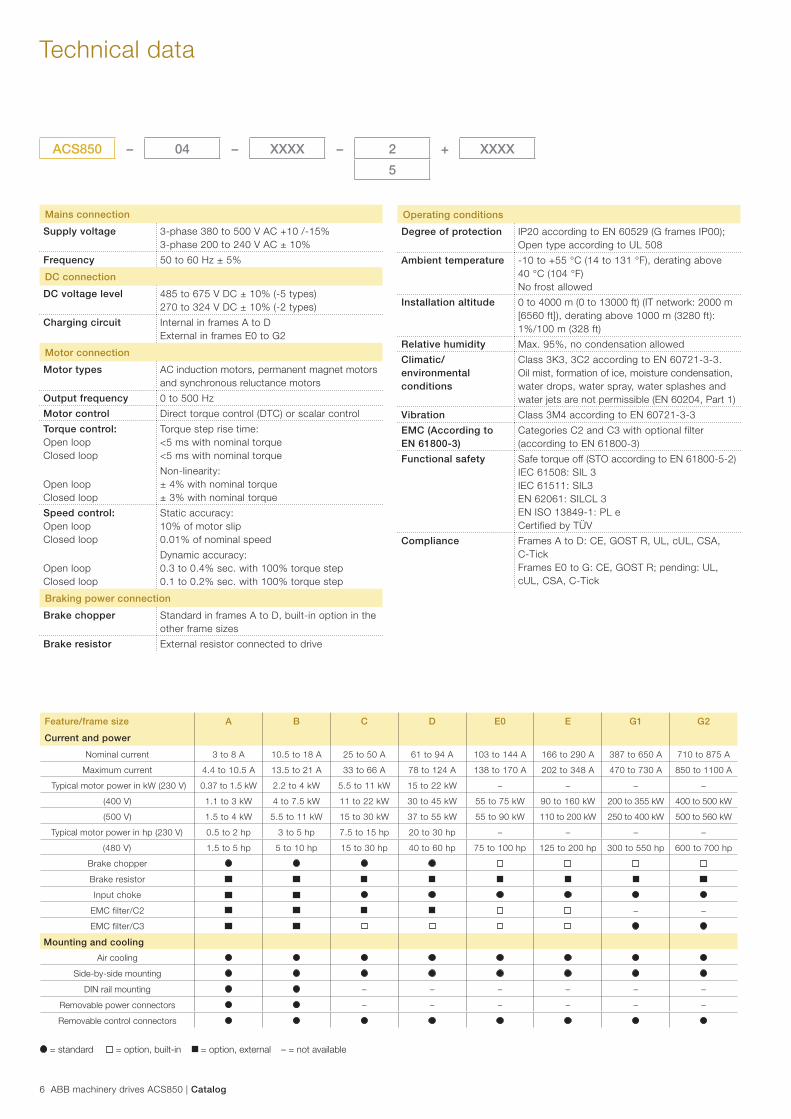
Technical data
Mains connection
Supply voltage 3-phase 380 to 500 V AC +10 /-15%3-phase 200 to 240 V AC ± 10%
Frequency 50 to 60 Hz ± 5%
DC connection
DC voltage level 485 to 675 V DC ± 10% (-5 types)270 to 324 V DC ± 10% (-2 types)
Charging circuit Internal in frames A to DExternal in frames E0 to G2
Motor connection
Motor types AC induction motors, permanent magnet motors and synchronous reluctance motors
Output frequency 0 to 500 Hz
Motor control Direct torque control (DTC) or scalar control
Torque control:Open loopClosed loop
Torque step rise time:<5 ms with nominal torque<5 ms with nominal torque
Open loopClosed loop
Non-linearity:± 4% with nominal torque± 3% with nominal torque
Speed control:Open loopClosed loop
Static accuracy:10% of motor slip0.01% of nominal speed
Open loopClosed loop
Dynamic accuracy:0.3 to 0.4% sec. with 100% torque step0.1 to 0.2% sec. with 100% torque step
Braking power connection
Brake chopper Standard in frames A to D, built-in option in the other frame sizes
Brake resistor External resistor connected to drive
Operating conditions
Degree of protection IP20 according to EN 60529 (G frames IP00);Open type according to UL 508
Ambient temperature -10 to +55 °C (14 to 131 °F), derating above 40 °C (104 °F)No frost allowed
Installation altitude 0 to 4000 m (0 to 13000 ft) (IT network: 2000 m [6560 ft]), derating above 1000 m (3280 ft): 1%/100 m (328 ft)
Relative humidity Max. 95%, no condensation allowed
Climatic/environmental conditions
Class 3K3, 3C2 according to EN 60721-3-3.Oil mist, formation of ice, moisture condensation, water drops, water spray, water splashes and water jets are not permissible (EN 60204, Part 1)
Vibration Class 3M4 according to EN 60721-3-3
EMC (According to EN 61800-3)
Categories C2 and C3 with optional filter (according to EN 61800-3)
Functional safety Safe torque off (STO according to EN 61800-5-2)IEC 61508: SIL 3IEC 61511: SIL3EN 62061: SILCL 3EN ISO 13849-1: PL eCertified by TÜV
Compliance Frames A to D: CE, GOST R, UL, cUL, CSA, C-TickFrames E0 to G: CE, GOST R; pending: UL, cUL, CSA, C-Tick
ACS850 – 04 – XXXX – 2 + XXXX
5
Feature/frame size A B C D E0 E G1 G2
Current and power
Nominal current 3 to 8 A 10.5 to 18 A 25 to 50 A 61 to 94 A 103 to 144 A 166 to 290 A 387 to 650 A 710 to 875 A
Maximum current 4.4 to 10.5 A 13.5 to 21 A 33 to 66 A 78 to 124 A 138 to 170 A 202 to 348 A 470 to 730 A 850 to 1100 A
Typical motor power in kW (230 V) 0.37 to 1.5 kW 2.2 to 4 kW 5.5 to 11 kW 15 to 22 kW – – – –
(400 V) 1.1 to 3 kW 4 to 7.5 kW 11 to 22 kW 30 to 45 kW 55 to 75 kW 90 to 160 kW 200 to 355 kW 400 to 500 kW
(500 V) 1.5 to 4 kW 5.5 to 11 kW 15 to 30 kW 37 to 55 kW 55 to 90 kW 110 to 200 kW 250 to 400 kW 500 to 560 kW
Typical motor power in hp (230 V) 0.5 to 2 hp 3 to 5 hp 7.5 to 15 hp 20 to 30 hp – – – –
(480 V) 1.5 to 5 hp 5 to 10 hp 15 to 30 hp 40 to 60 hp 75 to 100 hp 125 to 200 hp 300 to 550 hp 600 to 700 hp
Brake chopper
Brake resistor
Input choke
EMC filter/C2 – –
EMC filter/C3
Mounting and cooling
Air cooling
Side-by-side mounting
DIN rail mounting – – – – – –
Removable power connectors – – – – – –
Removable control connectors
= standard = option, built-in = option, external – = not available
Catalog | ABB machinery drives ACS850 7
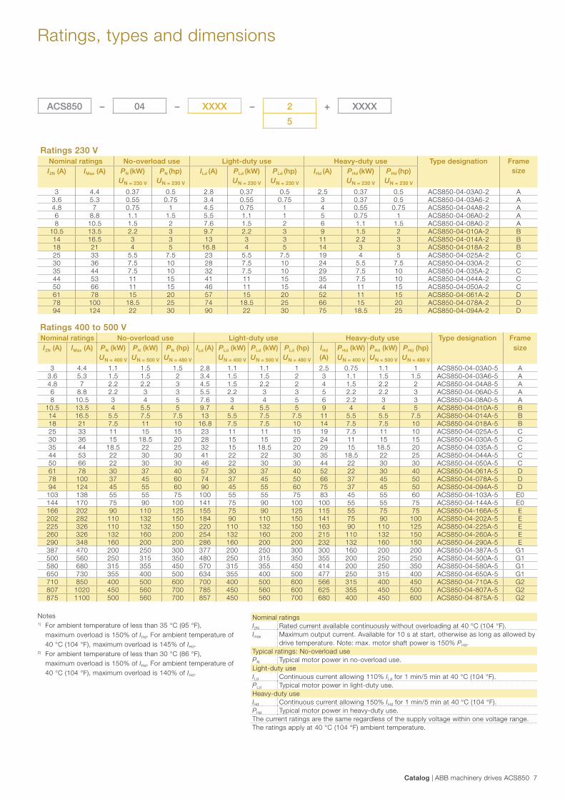
Ratings, types and dimensions
Notes1) For ambient temperature of less than 35 °C (95 °F), maximum overload is 150% of IHd. For ambient temperature of 40 °C (104 °F), maximum overload is 145% of IHd.2) For ambient temperature of less than 30 °C (86 °F), maximum overload is 150% of IHd. For ambient temperature of 40 °C (104 °F), maximum overload is 140% of IHd.
Nominal ratingsI2N Rated current available continuously without overloading at 40 °C (104 °F).Imax Maximum output current. Available for 10 s at start, otherwise as long as allowed by
drive temperature. Note: max. motor shaft power is 150% PHd.Typical ratings: No-overload usePN Typical motor power in no-overload use.Light-duty useILd Continuous current allowing 110% ILd for 1 min/5 min at 40 °C (104 °F).PLd Typical motor power in light-duty use.Heavy-duty useIHd Continuous current allowing 150% IHd for 1 min/5 min at 40 °C (104 °F).PHd Typical motor power in heavy-duty use.The current ratings are the same regardless of the supply voltage within one voltage range.The ratings apply at 40 °C (104 °F) ambient temperature.
Ratings 400 to 500 VNominal ratings No-overload use Light-duty use Heavy-duty use Type designation FrameI2N (A) IMax (A) PN (kW)
UN = 400 V
PN (kW)UN = 500 V
PN (hp)UN = 480 V
ILd (A) PLd (kW)UN = 400 V
PLd (kW)UN = 500 V
PLd (hp)UN = 480 V
IHd
(A)PHd (kW)UN = 400 V
PHd (kW)UN = 500 V
PHd (hp)UN = 480 V
size
3 4.4 1.1 1.5 1.5 2.8 1.1 1.1 1 2.5 0.75 1.1 1 ACS850-04-03A0-5 A3.6 5.3 1.5 1.5 2 3.4 1.5 1.5 2 3 1.1 1.5 1.5 ACS850-04-03A6-5 A4.8 7 2.2 2.2 3 4.5 1.5 2.2 2 4 1.5 2.2 2 ACS850-04-04A8-5 A6 8.8 2.2 3 3 5.5 2.2 3 3 5 2.2 2.2 3 ACS850-04-06A0-5 A8 10.5 3 4 5 7.6 3 4 5 6 2.2 3 3 ACS850-04-08A0-5 A
10.5 13.5 4 5.5 5 9.7 4 5.5 5 9 4 4 5 ACS850-04-010A-5 B14 16.5 5.5 7.5 7.5 13 5.5 7.5 7.5 11 5.5 5.5 7.5 ACS850-04-014A-5 B18 21 7.5 11 10 16.8 7.5 7.5 10 14 7.5 7.5 10 ACS850-04-018A-5 B25 33 11 15 15 23 11 11 15 19 7.5 11 10 ACS850-04-025A-5 C30 36 15 18.5 20 28 15 15 20 24 11 15 15 ACS850-04-030A-5 C35 44 18.5 22 25 32 15 18.5 20 29 15 18.5 20 ACS850-04-035A-5 C44 53 22 30 30 41 22 22 30 35 18.5 22 25 ACS850-04-044A-5 C50 66 22 30 30 46 22 30 30 44 22 30 30 ACS850-04-050A-5 C61 78 30 37 40 57 30 37 40 52 22 30 40 ACS850-04-061A-5 D78 100 37 45 60 74 37 45 50 66 37 45 50 ACS850-04-078A-5 D94 124 45 55 60 90 45 55 60 75 37 45 50 ACS850-04-094A-5 D
103 138 55 55 75 100 55 55 75 83 45 55 60 ACS850-04-103A-5 E0144 170 75 90 100 141 75 90 100 100 55 55 75 ACS850-04-144A-5 E0166 202 90 110 125 155 75 90 125 115 55 75 75 ACS850-04-166A-5 E202 282 110 132 150 184 90 110 150 141 75 90 100 ACS850-04-202A-5 E225 326 110 132 150 220 110 132 150 163 90 110 125 ACS850-04-225A-5 E260 326 132 160 200 254 132 160 200 215 110 132 150 ACS850-04-260A-5 E290 348 160 200 200 286 160 200 200 232 132 160 150 ACS850-04-290A-5 E387 470 200 250 300 377 200 250 300 300 160 200 200 ACS850-04-387A-5 G1500 560 250 315 350 480 250 315 350 355 200 250 250 ACS850-04-500A-5 G1580 680 315 355 450 570 315 355 450 414 200 250 350 ACS850-04-580A-5 G1650 730 355 400 500 634 355 400 500 477 250 315 400 ACS850-04-650A-5 G1710 850 400 500 600 700 400 500 600 566 315 400 450 ACS850-04-710A-5 G2807 1020 450 560 700 785 450 560 600 625 355 450 500 ACS850-04-807A-5 G2875 1100 500 560 700 857 450 560 700 680 400 450 600 ACS850-04-875A-5 G2
Ratings 230 VNominal ratings No-overload use Light-duty use Heavy-duty use Type designation Frame
sizeI2N (A) IMax (A) PN (kW)UN = 230 V
PN (hp) UN = 230 V
ILd (A) PLd (kW)UN = 230 V
PLd (hp)UN = 230 V
IHd (A) PHd (kW)UN = 230 V
PHd (hp)UN = 230 V
3 4.4 0.37 0.5 2.8 0.37 0.5 2.5 0.37 0.5 ACS850-04-03A0-2 A3.6 5.3 0.55 0.75 3.4 0.55 0.75 3 0.37 0.5 ACS850-04-03A6-2 A4.8 7 0.75 1 4.5 0.75 1 4 0.55 0.75 ACS850-04-04A8-2 A6 8.8 1.1 1.5 5.5 1.1 1 5 0.75 1 ACS850-04-06A0-2 A8 10.5 1.5 2 7.6 1.5 2 6 1.1 1.5 ACS850-04-08A0-2 A
10.5 13.5 2.2 3 9.7 2.2 3 9 1.5 2 ACS850-04-010A-2 B14 16.5 3 3 13 3 3 11 2.2 3 ACS850-04-014A-2 B18 21 4 5 16.8 4 5 14 3 3 ACS850-04-018A-2 B25 33 5.5 7.5 23 5.5 7.5 19 4 5 ACS850-04-025A-2 C30 36 7.5 10 28 7.5 10 24 5.5 7.5 ACS850-04-030A-2 C35 44 7.5 10 32 7.5 10 29 7.5 10 ACS850-04-035A-2 C44 53 11 15 41 11 15 35 7.5 10 ACS850-04-044A-2 C50 66 11 15 46 11 15 44 11 15 ACS850-04-050A-2 C61 78 15 20 57 15 20 52 11 15 ACS850-04-061A-2 D78 100 18.5 25 74 18.5 25 66 15 20 ACS850-04-078A-2 D94 124 22 30 90 22 30 75 18.5 25 ACS850-04-094A-2 D
ACS850 – 04 – XXXX – 2 + XXXX
5
8 ABB machinery drives ACS850 | Catalog
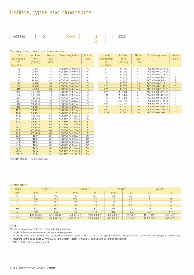
Ratings, types and dimensions
ACS850 – 04 – XXXX – 2 + XXXX
5
Heat
dissipation
W
Air fl ow
m3/h
(ft3/min)
Noise
level
dBA
Type designation Frame
size
UN = 230 V91 24 (14) 47 ACS850-04-03A0-2 A97 24 (14) 47 ACS850-04-03A6-2 A
114 24 (14) 47 ACS850-04-04A8-2 A134 24 (14) 47 ACS850-04-06A0-2 A154 24 (14) 47 ACS850-04-08A0-2 A183 48 (28) 39 ACS850-04-010A-2 B215 48 (28) 39 ACS850-04-014A-2 B274 48 (28) 39 ACS850-04-018A-2 B325 142 (84) 71 ACS850-04-025A-2 C421 142 (84) 71 ACS850-04-030A-2 C442 142 (84) 71 ACS850-04-035A-2 C462 200 (118) 71 ACS850-04-044A-2 C555 200 (118) 71 ACS850-04-050A-2 C730 290 (171) 70 ACS850-04-061A-2 D889 290 (171) 70 ACS850-04-078A-2 D
1054 290 (171) 70 ACS850-04-094A-2 D
NotesAll dimensions and weights are without additional options.1) Height is the maximum measure without clamping plates.2) An additional 50 mm (2 in) should be reserved for feedback cabling if FEN-01, -11 or -21 options are used (except for frame G1 and G2 with integrated control unit).3) Assistant control panel adds 23 mm (0.9 in) to the depth (except for frame G1 and G2 with integrated control unit).4) With +H381 optional cabling panel.
DimensionsFrame Height 1) Depth 2) 3) Width Weight
size mm in mm in mm in kg lbA 364 14.3 197 7.8 93 3.7 3 7 B 380 15.0 274 10.8 101 4.0 5 11 C 567 22.3 276 10.9 166 6.5 16 35 D 567 22.3 276 10.9 221 8.7 23 51 E0 602 23.7 354 13.9 276 10.9 35 77 E 700 27.6 443 17.4 312 12.3 67 147
G1 1462 (1560) 4) 57.6 (61.4) 4) 505 (515) 4) 19.9 (20.3) 4) 305 (329) 4) 12 (13) 4) 161 (191) 4) 355 (421) 4)
G2 1662 (1710) 4) 65.4 (67.3) 4) 505 (515) 4) 19.9 (20.3) 4) 305 (329) 4) 12 (13) 4) 199 (229) 4) 439 (505) 4)
* 65 dBA standby - 72 dBA running.
Cooling characteristics and noise levelsHeat
dissipation
W
Air fl ow
m3/h
(ft3/min)
Noise
level
dBA
Type designation Frame
size
UN = 400 V100 24 (14) 47 ACS850-04-03A0-5 A 106 24 (14) 47 ACS850-04-03A6-5 A 126 24 (14) 47 ACS850-04-04A8-5 A 148 24 (14) 47 ACS850-04-06A0-5 A 172 24 (14) 47 ACS850-04-08A0-5 A 212 48 (28) 39 ACS850-04-010A-5 B 250 48 (28) 39 ACS850-04-014A-5 B 318 48 (28 39 ACS850-04-018A-5 B 375 142 (84) 71 ACS850-04-025A-5 C 485 142 (84) 71 ACS850-04-030A-5 C
513 142 (84) 71 ACS850-04-035A-5 C 541 200 (118) 71 ACS850-04-044A-5 C 646 200 (118) 71 ACS850-04-050A-5 C 840 290 (171) 70 ACS850-04-061A-5 D
1020 290 (171) 70 ACS850-04-078A-5 D 1200 290 (171) 70 ACS850-04-094A-5 D 1190 168 (99) 65 ACS850-04-103A-5 E01440 405 (238) 65 ACS850-04-144A-5 E01940 405 (238) 65 ACS850-04-166A-5 E 2310 405 (238) 65 ACS850-04-202A-5 E 2819 405 (238) 65 ACS850-04-225A-5 E 3260 405 (238) 65 ACS850-04-260A-5 E 4200 405 (238) 65 ACS850-04-290A-5 E 4403 1200 72* ACS850-04-387A-5 G15602 1200 72* ACS850-04-500A-5 G16409 1200 72* ACS850-04-580A-5 G18122 1200 72* ACS850-04-650A-5 G18764 1200 72* ACS850-04-710A-5 G29862 1200 72* ACS850-04-807A-5 G2
10578 1420 72* ACS850-04-875A-5 G2
Catalog | ABB machinery drives ACS850 9
Standard control program
Based on direct torque control technology, the ACS850 offers highly advanced features. The ACS850 standard control program provides solutions to virtually all AC drives applications such as mixers, separators, extruders and conveyors.
Fast and easy commissioningThe ACS850 standard control program offers flexibility and extensive parameter settings. It consists of a simple, ready-made program that can easily be modified to meet specific application needs. Commissioning is also simplified by several standard software features.
Pre-programmed protection functionsA wide range of features provide protection for the drive, motor and the process:
− Ambient temperature − DC overvoltage − DC undervoltage − Drive temperature − Input phase loss − Overcurrent − Power limits − Short circuit
Programmable protection functions: − Adjustable power limits − Control signal supervision − Critical frequencies lock-out − Current and torque limits − Earth fault protection − External fault − Motor phase loss − Motor stall protection − Motor thermal protection − Motor underload protection − Panel loss
Program customizationIn addition to standard control program functionalities the ACS850 offers function block programming which makes it possible to replace relays or even a PLC.
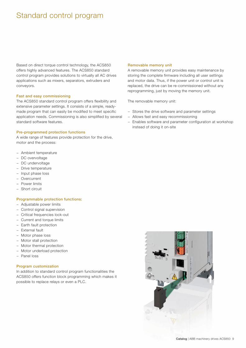
Removable memory unitA removable memory unit provides easy maintenance by storing the complete firmware including all user settings and motor data. Thus, if the power unit or control unit is replaced, the drive can be re-commissioned without any reprogramming, just by moving the memory unit.
The removable memory unit:
− Stores the drive software and parameter settings − Allows fast and easy recommissioning − Enables software and parameter configuration at workshop
instead of doing it on-site
10 ABB machinery drives ACS850 | Catalog
Standard software features
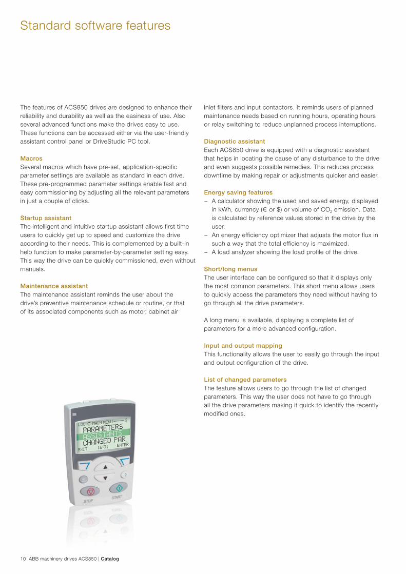
The features of ACS850 drives are designed to enhance their reliability and durability as well as the easiness of use. Also several advanced functions make the drives easy to use. These functions can be accessed either via the user-friendly assistant control panel or DriveStudio PC tool.
Macros Several macros which have pre-set, application-specific parameter settings are available as standard in each drive. These pre-programmed parameter settings enable fast and easy commissioning by adjusting all the relevant parameters in just a couple of clicks.
Startup assistantThe intelligent and intuitive startup assistant allows first time users to quickly get up to speed and customize the drive according to their needs. This is complemented by a built-in help function to make parameter-by-parameter setting easy. This way the drive can be quickly commissioned, even without manuals.
Maintenance assistantThe maintenance assistant reminds the user about the drive’s preventive maintenance schedule or routine, or that of its associated components such as motor, cabinet air
inlet filters and input contactors. It reminds users of planned maintenance needs based on running hours, operating hours or relay switching to reduce unplanned process interruptions.
Diagnostic assistantEach ACS850 drive is equipped with a diagnostic assistant that helps in locating the cause of any disturbance to the drive and even suggests possible remedies. This reduces process downtime by making repair or adjustments quicker and easier.
Energy saving features − A calculator showing the used and saved energy, displayed
in kWh, currency (€ or $) or volume of CO2 emission. Data is calculated by reference values stored in the drive by the user.
− An energy efficiency optimizer that adjusts the motor flux in such a way that the total efficiency is maximized.
− A load analyzer showing the load profile of the drive.
Short/long menusThe user interface can be configured so that it displays only the most common parameters. This short menu allows users to quickly access the parameters they need without having to go through all the drive parameters.
A long menu is available, displaying a complete list of parameters for a more advanced configuration.
Input and output mappingThis functionality allows the user to easily go through the input and output configuration of the drive.
List of changed parametersThe feature allows users to go through the list of changed parameters. This way the user does not have to go through all the drive parameters making it quick to identify the recently modified ones.
Catalog | ABB machinery drives ACS850 11
Standard I/O
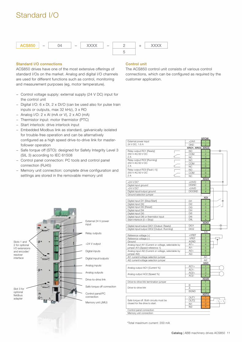
Standard I/O connectionsACS850 drives have one of the most extensive offerings of standard I/Os on the market. Analog and digital I/O channels are used for different functions such as control, monitoring and measurement purposes (eg, motor temperature).
− Control voltage supply: external supply (24 V DC) input for the control unit
− Digital I/O: 6 x DI, 2 x DI/O (can be used also for pulse train inputs or outputs, max 32 kHz), 3 x RO
− Analog I/O: 2 x AI (mA or V), 2 x AO (mA) − Thermistor input: motor thermistor (PTC) − Start interlock: drive interlock input − Embedded Modbus link as standard, galvanically isolated
for trouble-free operation and can be alternatively configured as a high speed drive-to-drive link for master-follower operation
− Safe torque off (STO): designed for Safety Integrity Level 3 (SIL 3) according to IEC 61508
− Control panel connection: PC tools and control panel connection (RJ45)
− Memory unit connection: complete drive configuration and settings are stored in the removable memory unit
*Total maximum current: 200 mA
External power input24 V DC, 1.6 A
Relay output RO1 [Ready]250 V AC/30 V DC2 ARelay output RO2 [Running]250 V AC/30 V DC2 A
Relay output RO3 [Fault (-1)]250 V AC/30 V DC2 A
+24 V DC*Digital input ground+24 V DC*Digital input/output groundGround selection jumper
Digital input DI1 [Stop/Start]Digital input DI2Digital input DI3 [Reset]Digital input DI4Digital input DI5Digital input DI6 or thermistor inputStart interlock (0 = Stop)
Digital input/output DIO1 [Output: Ready]Digital input/output DIO2 [Output: Running]
Reference voltage (+)Reference voltage (–)GroundAnalog input AI1 (Current or voltage, selectable by jumper AI1) [Speed reference 1]
AI1 current/voltage selection jumper
Analog input AI2 (Current or voltage, selectable by jumper AI2)
AI2 current/voltage selection jumper
Analog output AO1 [Current %]
Analog output AO2 [Speed %]
Drive-to-drive link termination jumper
Drive-to-drive link
Safe torque off. Both circuits must be closed for the drive to start.
Control panel connectionMemory unit connection
XPOW+24VIGND
NOXRO1, XRO2, XRO3
XD24
XDI
XDIO
XAI
XAO
XD2D
XSTO
COMNCNOCOMNCNOCOMNC
+24VDDIGND
DIOGND+24VD
DI1DI2DI3DI4DI5DI6DIIL
DIO1DIO2
+VREF-VREFAGNDAI1+AI1-AI2+AI2-
AO1+AO1-AO2+AO2-
BABGND
OUT1OUT2IN1IN2
12
123456
789
1234
123456A
12
1234567
AI1AI2
1234
123
T
1234
Control unitThe ACS850 control unit consists of various control connections, which can be configured as required by the customer application.
ACS850 – 04 – XXXX – 2 + XXXX
5
External 24 V power input
Relay outputs
+24 V output
Digital inputs
Analog inputs
Analog outputs
Drive-to-drive link
Safe torque off connection
Control panel/PC connection
Memory unit (JMU)
Slot 3 for optional fi eldbus adapter
Slots 1 and 2 for optional I/O extensions and encoder/resolver interface Digital input/outputs
12 ABB machinery drives ACS850 | Catalog
OptionsControl and communication modules
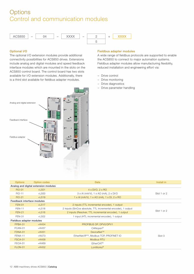
Optional I/OThe optional I/O extension modules provide additional connectivity possibilities for ACS850 drives. Extensions include analog and digital modules and speed feedback interface modules which are mounted in the slots on the ACS850 control board. The control board has two slots available for I/O extension modules. Additionally, there is a third slot available for fieldbus adapter modules.
Fieldbus adapter modulesA wide range of fieldbus protocols are supported to enable the ACS850 to connect to major automation systems. Fieldbus adapter modules allow manufacturing flexibility, reduced installation and engineering effort via:
− Drive control − Drive monitoring − Drive diagnostics − Drive parameter handling
Analog and digital extension
Feedback interface
Fieldbus adapter
Options Option codes Data Install in
Analog and digital extension modules
FIO-01 +L501 4 x DI/O, 2 x RO
Slot 1 or 2FIO-11 +L500 3 x AI (mA/V), 1 x AO (mA), 2 x DI/O
FIO-21 +L519 1 x AI (mA/V), 1 x AO (mA), 1 x DI, 2 x RO
Feedback interface modules
FEN-01 +L517 2 inputs (TTL incremental encoder), 1 output
Slot 1 or 2FEN-11 +L518 2 inputs (SinCos absolute, TTL incremental encoder), 1 output
FEN-21 +L516 2 inputs (Resolver, TTL incremental encoder), 1 output
FEN-31 +L502 1 input (HTL incremental encoder), 1 output
Fieldbus adapter modules
FPBA-01 +K454 PROFIBUS DP, DPV0/DPV1
Slot 3
FCAN-01 +K457 CANopen®
FDNA-01 +K451 DeviceNetTM
FENA-11 +K473 EtherNet/IPTM, Modbus TCP, PROFINET IO
FSCA-01 +K458 Modbus RTU
FECA-01 +K469 EtherCAT®
FLON-01 +K452 LonWorks®
ACS850 – 04 – XXXX – 2 + XXXX
5
Catalog | ABB machinery drives ACS850 13
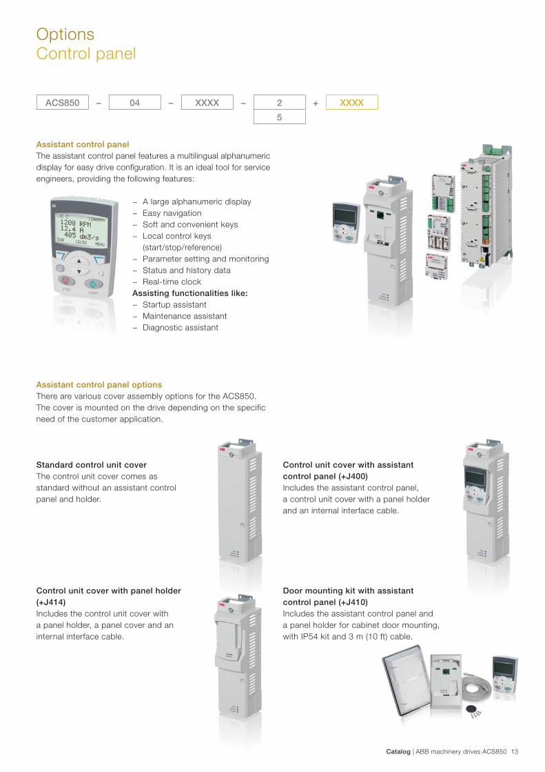
OptionsControl panel
Assistant control panelThe assistant control panel features a multilingual alphanumeric display for easy drive confi guration. It is an ideal tool for service engineers, providing the following features:
− A large alphanumeric display − Easy navigation − Soft and convenient keys − Local control keys
(start/stop/reference) − Parameter setting and monitoring − Status and history data − Real-time clock
Assisting functionalities like: − Startup assistant − Maintenance assistant − Diagnostic assistant
Assistant control panel optionsThere are various cover assembly options for the ACS850. The cover is mounted on the drive depending on the specific need of the customer application.
Standard control unit coverThe control unit cover comes as standard without an assistant control panel and holder.
Control unit cover with assistant control panel (+J400)Includes the assistant control panel, a control unit cover with a panel holder and an internal interface cable.
Control unit cover with panel holder (+J414)Includes the control unit cover with a panel holder, a panel cover and an internal interface cable.
Door mounting kit with assistant control panel (+J410)Includes the assistant control panel and a panel holder for cabinet door mounting, with IP54 kit and 3 m (10 ft) cable.
ACS850 – 04 – XXXX – 2 + XXXX
5
14 ABB machinery drives ACS850 | Catalog
OptionsG frame drive modules
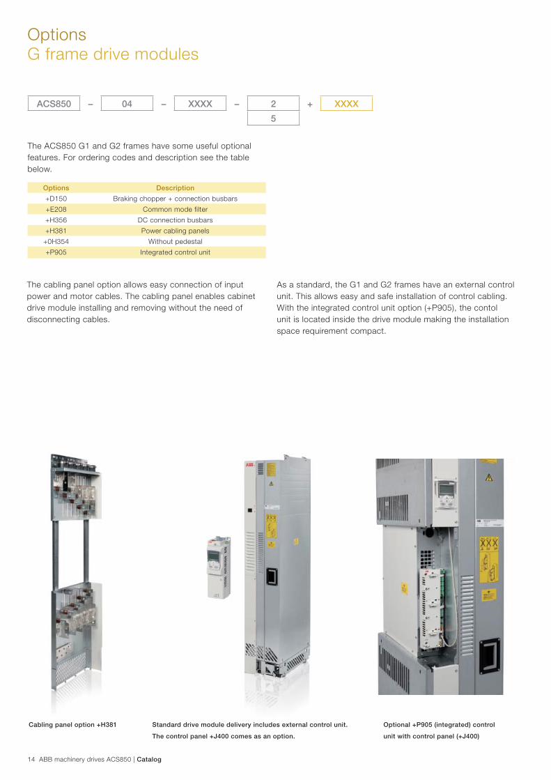
The ACS850 G1 and G2 frames have some useful optional features. For ordering codes and description see the table below.
Cabling panel option +H381 Standard drive module delivery includes external control unit.
The control panel +J400 comes as an option.
Optional +P905 (integrated) control
unit with control panel (+J400)
The cabling panel option allows easy connection of input power and motor cables. The cabling panel enables cabinet drive module installing and removing without the need of disconnecting cables.
As a standard, the G1 and G2 frames have an external control unit. This allows easy and safe installation of control cabling. With the integrated control unit option (+P905), the contol unit is located inside the drive module making the installation space requirement compact.
Options Description
+D150 Braking chopper + connection busbars
+E208 Common mode filter
+H356 DC connection busbars
+H381 Power cabling panels
+0H354 Without pedestal
+P905 Integrated control unit
ACS850 – 04 – XXXX – 2 + XXXX
5
Catalog | ABB machinery drives ACS850 15
OptionsEMC filters
Electromagnetic Compatibility (EMC) and modulesThe electrical/electronic equipment must be able to operate without problems within an electromagnetic environment. This is called immunity. The ACS850 is designed to have adequate immunity against interference from other equipment. Likewise, the equipment must not disturb or interfere with any other product or system within its locality. This is called emission. Each ACS850 model can be equipped with a built-in filter to reduce high frequency emission.
EMC standards The EMC product standard EN 61800-3 (2004) covers the specific EMC requirements stated for drives (tested with motor and cable) within the EU.
EMC standards such as EN 55011, or EN 61000-6-3/4, are applicable to industrial and domestic equipment and systems including drive components inside. Drive units complying with requirements of EN 61800-3 are compliant with comparable categories in EN 55011 and EN 61000-6-3/4, but not necessarily vice versa. EN 55011 and EN 61000-6-3/4 do not specify cable length nor require a motor to be connected as a load. The emission limits are comparable according to the following EMC standards table.
1st environment vs 2nd environment
1st environment (category C1 to C2)1st environment includes domestic premises. It also includes establishments directly connected without intermediate transformer to a low-voltage power supply network which supplies buildings used for domestic purposes.
2nd environment (category C3 to C4)2nd environment includes all establishments other than those directly connected to a low-voltage power supply network which supplies buildings used for domestic purposes.
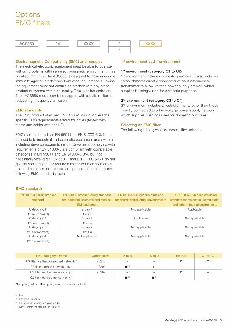
Selecting an EMC filterThe following table gives the correct filter selection.
EMC standards
EN61800-3 (2004) product
standard
EN 55011, product family standard
for industrial, scientifi c and medical
(ISM) equipment
EN 61000-6-4, generic emission
standard for industrial environments
EN 61000-6-3, generic emission
standard for residential, commercial
and light-industrial environment
Category C1
(1st environment)
Group 1
Class B
Not applicable Applicable
Category C2
(1st environment)
Group 1
Class A
Applicable Not applicable
Category C3
(2nd environment)
Group 2
Class A
Not applicable Not applicable
Category C4
(2nd environment)
Not applicable Not applicable Not applicable
Notes 1) External, plug-in 2) External accesory, no plus code* Max. cable length 100 m (328 ft)
EMC category / frame Option code A to B C to D E0 to E G1 to G2
C3 filter, earthed/unearthed network * +E210 – –
C3 filter earthed network only * +E200 1) – –
C2 filter, earthed network only * +E202 – – –
C2 filter, earthed network only * 2) 2) – –
= option, built-in = option, external – = not available
ACS850 – 04 – XXXX – 2 + XXXX
5
16 ABB machinery drives ACS850 | Catalog
OptionsMains circuit
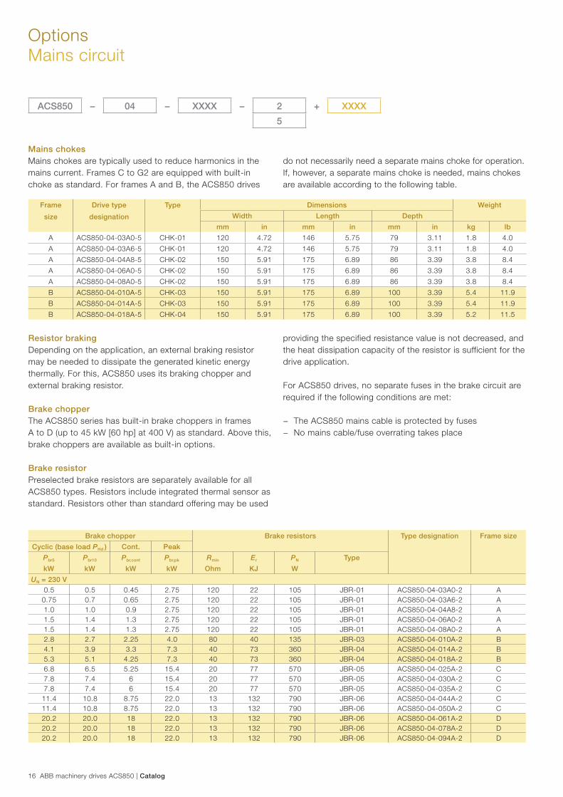
Mains chokesMains chokes are typically used to reduce harmonics in the mains current. Frames C to G2 are equipped with built-in choke as standard. For frames A and B, the ACS850 drives
Frame
size
Drive type
designation
Type Dimensions Weight
Width Length Depth
mm in mm in mm in kg lb
A ACS850-04-03A0-5 CHK-01 120 4.72 146 5.75 79 3.11 1.8 4.0
A ACS850-04-03A6-5 CHK-01 120 4.72 146 5.75 79 3.11 1.8 4.0
A ACS850-04-04A8-5 CHK-02 150 5.91 175 6.89 86 3.39 3.8 8.4
A ACS850-04-06A0-5 CHK-02 150 5.91 175 6.89 86 3.39 3.8 8.4
A ACS850-04-08A0-5 CHK-02 150 5.91 175 6.89 86 3.39 3.8 8.4
B ACS850-04-010A-5 CHK-03 150 5.91 175 6.89 100 3.39 5.4 11.9
B ACS850-04-014A-5 CHK-03 150 5.91 175 6.89 100 3.39 5.4 11.9
B ACS850-04-018A-5 CHK-04 150 5.91 175 6.89 100 3.39 5.2 11.5
ACS850 – 04 – XXXX – 2 + XXXX
5
do not necessarily need a separate mains choke for operation. If, however, a separate mains choke is needed, mains chokes are available according to the following table.
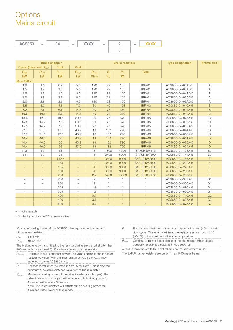
Resistor brakingDepending on the application, an external braking resistor may be needed to dissipate the generated kinetic energy thermally. For this, ACS850 uses its braking chopper and external braking resistor.
Brake chopperThe ACS850 series has built-in brake choppers in frames A to D (up to 45 kW [60 hp] at 400 V) as standard. Above this, brake choppers are available as built-in options.
Brake resistorPreselected brake resistors are separately available for all ACS850 types. Resistors include integrated thermal sensor as standard. Resistors other than standard offering may be used
providing the specified resistance value is not decreased, and the heat dissipation capacity of the resistor is sufficient for the drive application.
For ACS850 drives, no separate fuses in the brake circuit are required if the following conditions are met:
− The ACS850 mains cable is protected by fuses − No mains cable/fuse overrating takes place
Brake chopper Brake resistors Type designation Frame size
Cyclic (base load PHd ) Cont. Peak
Pbr5 Pbr10 Pbr,cont Pbr,pk Rmin Er PN Type
kW kW kW kW Ohm KJ W
UN = 230 V
0.5 0.5 0.45 2.75 120 22 105 JBR-01 ACS850-04-03A0-2 A0.75 0.7 0.65 2.75 120 22 105 JBR-01 ACS850-04-03A6-2 A1.0 1.0 0.9 2.75 120 22 105 JBR-01 ACS850-04-04A8-2 A1.5 1.4 1.3 2.75 120 22 105 JBR-01 ACS850-04-06A0-2 A1.5 1.4 1.3 2.75 120 22 105 JBR-01 ACS850-04-08A0-2 A2.8 2.7 2.25 4.0 80 40 135 JBR-03 ACS850-04-010A-2 B4.1 3.9 3.3 7.3 40 73 360 JBR-04 ACS850-04-014A-2 B5.3 5.1 4.25 7.3 40 73 360 JBR-04 ACS850-04-018A-2 B6.8 6.5 5.25 15.4 20 77 570 JBR-05 ACS850-04-025A-2 C7.8 7.4 6 15.4 20 77 570 JBR-05 ACS850-04-030A-2 C7.8 7.4 6 15.4 20 77 570 JBR-05 ACS850-04-035A-2 C
11.4 10.8 8.75 22.0 13 132 790 JBR-06 ACS850-04-044A-2 C11.4 10.8 8.75 22.0 13 132 790 JBR-06 ACS850-04-050A-2 C20.2 20.0 18 22.0 13 132 790 JBR-06 ACS850-04-061A-2 D20.2 20.0 18 22.0 13 132 790 JBR-06 ACS850-04-078A-2 D20.2 20.0 18 22.0 13 132 790 JBR-06 ACS850-04-094A-2 D
Catalog | ABB machinery drives ACS850 17
OptionsMains circuit
ACS850 – 04 – XXXX – 2 + XXXX
5
Brake chopper Brake resistors Type designation Frame size
Cyclic (base load PHd) Cont. Peak
Pbr5 Pbr10 Pbr,cont Pbr,pk Rmin Er PN Type
kW kW kW kW Ohm KJ W
UN = 400 V
1.0 1.0 0.9 5.5 120 22 105 JBR-01 ACS850-04-03A0-5 A1.5 1.4 1.3 5.5 120 22 105 JBR-01 ACS850-04-03A6-5 A2.0 1.9 1.8 5.5 120 22 105 JBR-01 ACS850-04-04A8-5 A3.0 2.8 2.6 5.5 120 22 105 JBR-01 ACS850-04-06A0-5 A3.0 2.8 2.6 5.5 120 22 105 JBR-01 ACS850-04-08A0-5 A5.5 5.3 4.5 7.9 80 40 135 JBR-03 ACS850-04-010A-5 B8.2 7.8 6.6 14.6 40 73 360 JBR-04 ACS850-04-014A-5 B
10.5 10.1 8.5 14.6 40 73 360 JBR-04 ACS850-04-018A-5 B13.6 12.9 10.5 30.7 20 77 570 JBR-05 ACS850-04-025A-5 C15.5 14.7 12 30.7 20 77 570 JBR-05 ACS850-04-030A-5 C15.5 14.7 12 30.7 20 77 570 JBR-05 ACS850-04-035A-5 C22.7 21.5 17.5 43.9 13 132 790 JBR-06 ACS850-04-044A-5 C22.7 21.5 17.5 43.9 13 132 790 JBR-06 ACS850-04-050A-5 C40.4 40.0 36 43.9 13 132 790 JBR-06 ACS850-04-061A-5 D40.4 40.0 36 43.9 13 132 790 JBR-06 ACS850-04-078A-5 D40.4 40.0 36 43.9 13 132 790 JBR-06 ACS850-04-094A-5 D67.5 66 61 – 8 1800 4500 SAFUR90F575 ACS850-04-103A-5 E085 83 75 – 6 2400 6000 SAFUR80F500 ACS850-04-144A-5 E0– – 112.5 – 4 3600 9000 SAFUR125F500 ACS850-04-166A-5 E – – 135 – 4 3600 9000 SAFUR125F500 ACS850-04-202A-5 E – – 135 – 4 3600 9000 SAFUR125F500 ACS850-04-225A-5 E – – 160 – 4 3600 9000 SAFUR125F500 ACS850-04-260A-5 E – – 200 – 2.7 5400 13500 SAFUR200F500 ACS850-04-290A-5 E – – 250 – 2 * * * ACS850-04-387A-5 G1– – 250 – 2 * * * ACS850-04-500A-5 G1– – 355 – 1.3 * * * ACS850-04-580A-5 G1– – 355 – 1.3 * * * ACS850-04-650A-5 G1– – 400 – 0.7 * * * ACS850-04-710A-5 G2– – 400 – 0.7 * * * ACS850-04-807A-5 G2– – 400 – 0.7 * * * ACS850-04-875A-5 G2
Maximum braking power of the ACS850 drive equipped with standard chopper and resistor
Pbr5 5 s/1 min
Pbr10 10 s/1 min
The braking energy transmitted to the resistor during any period shorter than 400 seconds may exceed Er. (Er varies depending on the resistor).
Pbr,cont Continuous brake chopper power. The value applies to the minimum resitstance value. With a higher resistance value the Pbr,cont may increase in some ACS850 drives.
R Resistance value for the listed resistor type. Note: This is also the minimum allowable resistance value for the brake resistor.
Pbr,pk Maximum braking power of the drive (inverter and chopper). The drive (inverter and chopper) will withstand this braking power for1 second within every 10 seconds.Note: The listed resistors will withstand this braking power for1 second within every 120 seconds.
– = not available
* Contact your local ABB representative
Er Energy pulse that the resistor assembly will withstand (400 seconds duty cycle). This energy will heat the resistor element from 40 °C (104 °F) to the maximum allowable temperature.
Prcont Continuous power (heat) dissipation of the resistor when placed correctly. Energy Er dissipates in 400 seconds.
All brake resistors are to be installed outside the converter module.
The SAFUR brake resistors are built-in in an IP00 metal frame.
18 ABB machinery drives ACS850 | Catalog
OptionsMains circuit
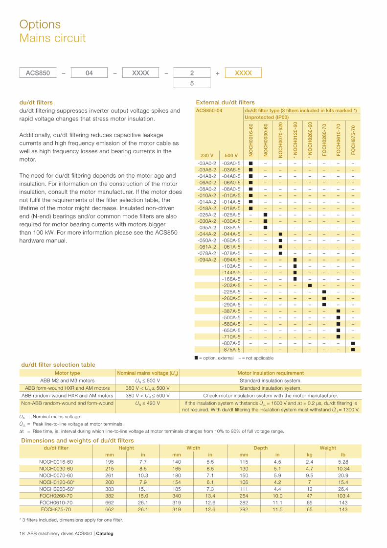
du/dt filters du/dt filtering suppresses inverter output voltage spikes and rapid voltage changes that stress motor insulation.
Additionally, du/dt filtering reduces capacitive leakage currents and high frequency emission of the motor cable as well as high frequency losses and bearing currents in the motor.
The need for du/dt filtering depends on the motor age and insulation. For information on the construction of the motor insulation, consult the motor manufacturer. If the motor does not fulfil the requirements of the filter selection table, the lifetime of the motor might decrease. Insulated non-driven end (N-end) bearings and/or common mode filters are also required for motor bearing currents with motors bigger than 100 kW. For more information please see the ACS850 hardware manual.
External du/dt filtersACS850-04 du/dt fi lter type (3 fi lters included in kits marked *)
Unprotected (IP00)
NO
CH
0016
-60
NO
CH
0030
-60
NO
CH
0070
-620
* N
OC
H01
20-6
0
* N
OC
H02
60-6
0
FO
CH
0260
-70
FO
CH
0610
-70
FO
CH
875-
70
230 V 500 V
-03A0-2 -03A0-5 – – – – – – –-03A6-2 -03A6-5 – – – – – – –-04A8-2 -04A8-5 – – – – – – –-06A0-2 -06A0-5 – – – – – – –-08A0-2 -08A0-5 – – – – – – –-010A-2 -010A-5 – – – – – – –-014A-2 -014A-5 – – – – – – –-018A-2 -018A-5 – – – – – – –-025A-2 -025A-5 – – – – – – –-030A-2 -030A-5 – – – – – – –-035A-2 -035A-5 – – – – – – –-044A-2 -044A-5 – – – – – – –-050A-2 -050A-5 – – – – – – –-061A-2 -061A-5 – – – – – – –-078A-2 -078A-5 – – – – – – –-094A-2 -094A-5 – – – – – – –
-103A-5 – – – – – – –-144A-5 – – – – – – –-166A-5 – – – – – – –-202A-5 – – – – – – –-225A-5 – – – – – – –-260A-5 – – – – – – –-290A-5 – – – – – – –-387A-5 – – – – – – –-500A-5 – – – – – – –-580A-5 – – – – – – –-650A-5 – – – – – – –-710A-5 – – – – – – –-807A-5 – – – – – – –-875A-5 – – – – – – –
ACS850 – 04 – XXXX – 2 + XXXX
5
du/dt filter selection tableMotor type Nominal mains voltage (UN) Motor insulation requirement
ABB M2 and M3 motors UN 500 V Standard insulation system.
ABB form-wound HXR and AM motors 380 V < UN 500 V Standard insulation system.
ABB random-wound HXR and AM motors 380 V < UN 500 V Check motor insulation system with the motor manufacturer.
Non-ABB random-wound and form-wound UN 420 V If the insulation system withstands ÛLL = 1600 V and t = 0.2 µs, du/dt fi ltering is not required. With du/dt fi ltering the insulation system must withstand ÛLL= 1300 V.
UN = Nominal mains voltage.
ÛLL = Peak line-to-line voltage at motor terminals.
t = Rise time, ie, interval during which line-to-line voltage at motor terminals changes from 10% to 90% of full voltage range.
Dimensions and weights of du/dt filtersdu/dt fi lter Height Width Depth Weight
mm in mm in mm in kg lb
NOCH0016-60 195 7.7 140 5.5 115 4.5 2.4 5.28NOCH0030-60 215 8.5 165 6.5 130 5.1 4.7 10.34NOCH0070-60 261 10.3 180 7.1 150 5.9 9.5 20.9NOCH0120-60* 200 7.9 154 6.1 106 4.2 7 15.4NOCH0260-60* 383 15.1 185 7.3 111 4.4 12 26.4FOCH0260-70 382 15.0 340 13.4 254 10.0 47 103.4FOCH0610-70 662 26.1 319 12.6 282 11.1 65 143FOCH875-70 662 26.1 319 12.6 292 11.5 65 143
* 3 filters included, dimensions apply for one filter.
= option, external – = not applicable
Catalog | ABB machinery drives ACS850 19
OptionsPC tools
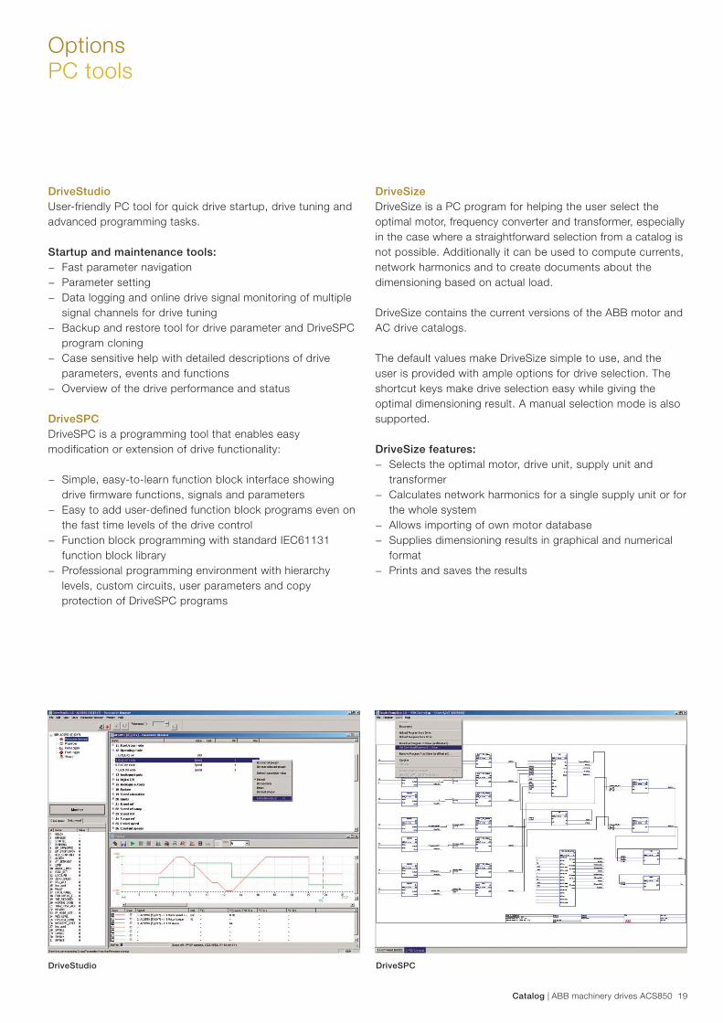
DriveStudioUser-friendly PC tool for quick drive startup, drive tuning and advanced programming tasks.
Startup and maintenance tools: − Fast parameter navigation − Parameter setting − Data logging and online drive signal monitoring of multiple
signal channels for drive tuning − Backup and restore tool for drive parameter and DriveSPC
program cloning − Case sensitive help with detailed descriptions of drive
parameters, events and functions − Overview of the drive performance and status
DriveSPCDriveSPC is a programming tool that enables easy modification or extension of drive functionality:
− Simple, easy-to-learn function block interface showing drive firmware functions, signals and parameters
− Easy to add user-defined function block programs even on the fast time levels of the drive control
− Function block programming with standard IEC61131 function block library
− Professional programming environment with hierarchy levels, custom circuits, user parameters and copy protection of DriveSPC programs
DriveSizeDriveSize is a PC program for helping the user select the optimal motor, frequency converter and transformer, especially in the case where a straightforward selection from a catalog is not possible. Additionally it can be used to compute currents, network harmonics and to create documents about the dimensioning based on actual load.
DriveSize contains the current versions of the ABB motor and AC drive catalogs.
The default values make DriveSize simple to use, and the user is provided with ample options for drive selection. The shortcut keys make drive selection easy while giving the optimal dimensioning result. A manual selection mode is also supported.
DriveSize features: − Selects the optimal motor, drive unit, supply unit and
transformer − Calculates network harmonics for a single supply unit or for
the whole system − Allows importing of own motor database − Supplies dimensioning results in graphical and numerical
format − Prints and saves the results
DriveStudio DriveSPC
20 ABB machinery drives ACS850 | Catalog
OptionsCrane control program (+N5050 +N3050)
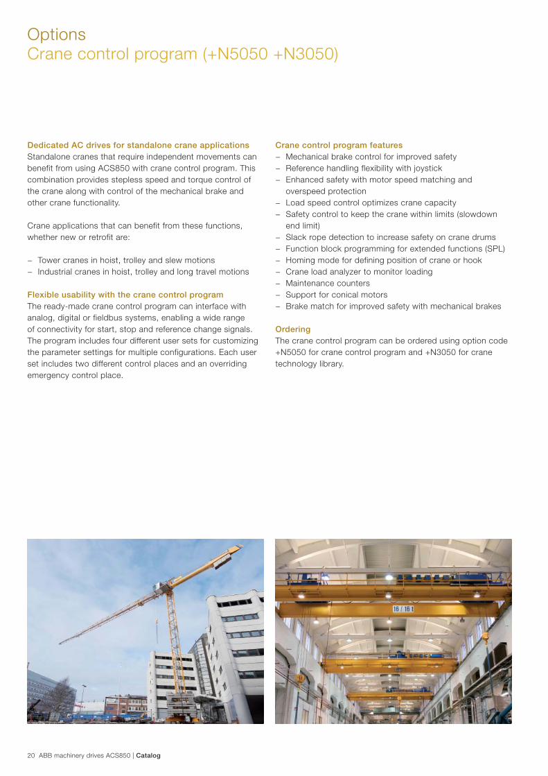
Dedicated AC drives for standalone crane applicationsStandalone cranes that require independent movements can benefit from using ACS850 with crane control program. This combination provides stepless speed and torque control of the crane along with control of the mechanical brake and other crane functionality.
Crane applications that can benefit from these functions, whether new or retrofit are:
− Tower cranes in hoist, trolley and slew motions − Industrial cranes in hoist, trolley and long travel motions
Flexible usability with the crane control programThe ready-made crane control program can interface with analog, digital or fieldbus systems, enabling a wide range of connectivity for start, stop and reference change signals. The program includes four different user sets for customizing the parameter settings for multiple configurations. Each user set includes two different control places and an overriding emergency control place.
Crane control program features − Mechanical brake control for improved safety − Reference handling flexibility with joystick − Enhanced safety with motor speed matching and
overspeed protection − Load speed control optimizes crane capacity − Safety control to keep the crane within limits (slowdown
end limit) − Slack rope detection to increase safety on crane drums − Function block programming for extended functions (SPL) − Homing mode for defining position of crane or hook − Crane load analyzer to monitor loading − Maintenance counters − Support for conical motors − Brake match for improved safety with mechanical brakes
OrderingThe crane control program can be ordered using option code +N5050 for crane control program and +N3050 for crane technology library.
Catalog | ABB machinery drives ACS850 21
OptionsSynchronous reluctance motor and drive package (+N7502)
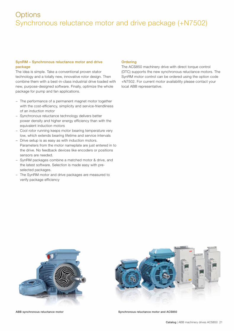
SynRM – Synchronous reluctance motor and drive packageThe idea is simple. Take a conventional proven stator technology and a totally new, innovative rotor design. Then combine them with a best-in-class industrial drive loaded with new, purpose-designed software. Finally, optimize the whole package for pump and fan applications.
− The performance of a permanent magnet motor together with the cost-efficiency, simplicity and service-friendliness of an induction motor
− Synchronous reluctance technology delivers better power density and higher energy efficiency than with the equivalent induction motors
− Cool rotor running keeps motor bearing temperature very low, which extends bearing lifetime and service intervals
− Drive setup is as easy as with induction motors. Parameters from the motor nameplate are just entered in to the drive. No feedback devices like encoders or positions sensors are needed.
− SynRM packages combine a matched motor & drive, and the latest software. Selection is made easy with pre-selected packages.
− The SynRM motor and drive packages are measured to verify package efficiency
ABB synchronous reluctance motor Synchronous reluctance motor and ACS850
OrderingThe ACS850 machinery drive with direct torque control (DTC) supports the new synchronous reluctance motors. The SynRM motor control can be ordered using the option code +N7502. For current motor availability please contact your local ABB representative.
22 ABB machinery drives ACS850 | Catalog
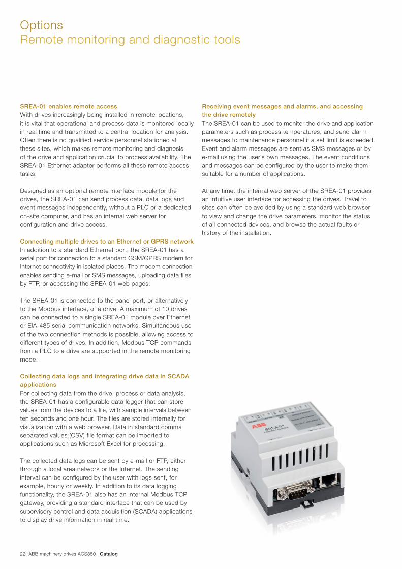
SREA-01 enables remote accessWith drives increasingly being installed in remote locations, it is vital that operational and process data is monitored locally in real time and transmitted to a central location for analysis. Often there is no qualified service personnel stationed at these sites, which makes remote monitoring and diagnosis of the drive and application crucial to process availability. The SREA-01 Ethernet adapter performs all these remote access tasks.
Designed as an optional remote interface module for the drives, the SREA-01 can send process data, data logs and event messages independently, without a PLC or a dedicated on-site computer, and has an internal web server for configuration and drive access.
Connecting multiple drives to an Ethernet or GPRS networkIn addition to a standard Ethernet port, the SREA-01 has a serial port for connection to a standard GSM/GPRS modem for Internet connectivity in isolated places. The modem connection enables sending e-mail or SMS messages, uploading data fi les by FTP, or accessing the SREA-01 web pages.
The SREA-01 is connected to the panel port, or alternatively to the Modbus interface, of a drive. A maximum of 10 drives can be connected to a single SREA-01 module over Ethernet or EIA-485 serial communication networks. Simultaneous use of the two connection methods is possible, allowing access to different types of drives. In addition, Modbus TCP commands from a PLC to a drive are supported in the remote monitoring mode.
Collecting data logs and integrating drive data in SCADA applicationsFor collecting data from the drive, process or data analysis, the SREA-01 has a configurable data logger that can store values from the devices to a fi le, with sample intervals between ten seconds and one hour. The files are stored internally for visualization with a web browser. Data in standard comma separated values (CSV) file format can be imported to applications such as Microsoft Excel for processing.
The collected data logs can be sent by e-mail or FTP, either through a local area network or the Internet. The sending interval can be configured by the user with logs sent, for example, hourly or weekly. In addition to its data logging functionality, the SREA-01 also has an internal Modbus TCP gateway, providing a standard interface that can be used by supervisory control and data acquisition (SCADA) applications to display drive information in real time.
OptionsRemote monitoring and diagnostic tools
Receiving event messages and alarms, and accessing the drive remotelyThe SREA-01 can be used to monitor the drive and application parameters such as process temperatures, and send alarm messages to maintenance personnel if a set limit is exceeded. Event and alarm messages are sent as SMS messages or by e-mail using the user´s own messages. The event conditions and messages can be configured by the user to make them suitable for a number of applications.
At any time, the internal web server of the SREA-01 provides an intuitive user interface for accessing the drives. Travel to sites can often be avoided by using a standard web browser to view and change the drive parameters, monitor the status of all connected devices, and browse the actual faults or history of the installation.
Catalog | ABB machinery drives ACS850 23
Expertise at every stage of the value chain
Secure uptime throughout the drive life cycle
Whether you operate in industry, commerce or a utility your aims remain the same: to keep your motor-driven applications running consistently and efficiently. The life cycle services for ABB drives can help you achieve these aims by maximizing the uptime of your process while ensuring the optimum lifetime of ABB drives in a predictable, safe and low-cost manner.
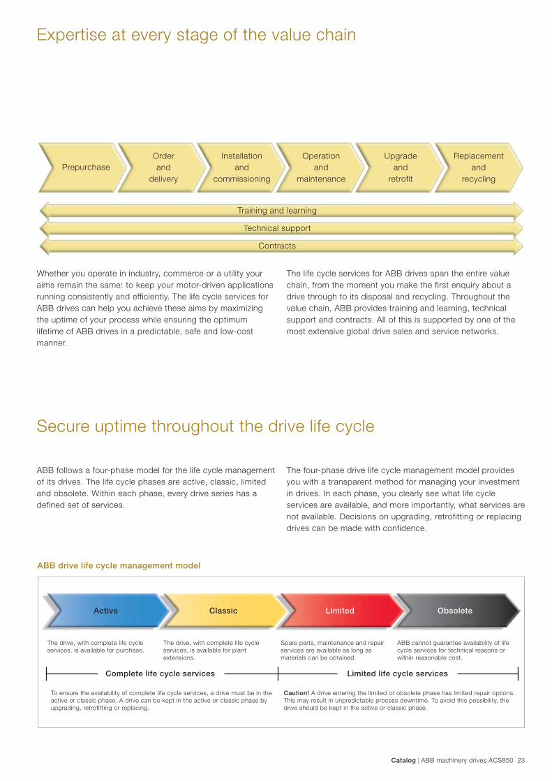
ABB follows a four-phase model for the life cycle management of its drives. The life cycle phases are active, classic, limited and obsolete. Within each phase, every drive series has a defined set of services.
ABB drive life cycle management model
PrepurchaseOrder and
delivery
Installation and
commissioning
Operation and
maintenance
Upgrade and
retrofit
Replacementand
recycling
Training and learning
Technical support
Contracts
The life cycle services for ABB drives span the entire value chain, from the moment you make the first enquiry about a drive through to its disposal and recycling. Throughout the value chain, ABB provides training and learning, technical support and contracts. All of this is supported by one of the most extensive global drive sales and service networks.
The four-phase drive life cycle management model provides you with a transparent method for managing your investment in drives. In each phase, you clearly see what life cycle services are available, and more importantly, what services are not available. Decisions on upgrading, retrofitting or replacing drives can be made with confidence.
The drive, with complete life cycle services, is available for purchase.
The drive, with complete life cycle services, is available for plant extensions.
Spare parts, maintenance and repair services are available as long as materials can be obtained.
ABB cannot guarantee availability of life cycle services for technical reasons or within reasonable cost.
Complete life cycle services Limited life cycle services
To ensure the availability of complete life cycle services, a drive must be in the active or classic phase. A drive can be kept in the active or classic phase by upgrading, retrofitting or replacing.
Caution! A drive entering the limited or obsolete phase has limited repair options. This may result in unpredictable process downtime. To avoid this possibility, the drive should be kept in the active or classic phase.
Active Classic Limited Obsolete

Contact us
3AU
A00
0004
1481
RE
V H
EN
5.9
.201
3 #1
6884© Copyright 2013 ABB. All rights reserved.
Specifi cations subject to change without notice.For more information please contact your local ABB representative or visit:
www.abb.com/driveswww.abb.com/drivespartners