ab22 class b amplifier (push-pull emitter follower ...cgibp.com/data/lab_manual/ab22 class b...
TRANSCRIPT

AB22 Class B Amplifier (Push-Pull Emitter Follower)
Operating Manual Ver.1.1
An ISO 9001 : 2000 company
94-101, Electronic Complex Pardesipura, Indore- 452010, India Tel : 91-731- 2570301/02, 4211100 Fax: 91- 731- 2555643 e mail : [email protected] Website : www.scientech.bz Toll free : 1800-103-5050

AB22
Scientech Technologies Pvt. Ltd. 2

AB22
Scientech Technologies Pvt. Ltd. 3
RoHS Compliance
Scientech Products are RoHS Complied. RoHS Directive concerns with the restrictive use of Hazardous substances (Pb, Cd, Cr, Hg, Br compounds) in electric and electronic equipments. Scientech products are “Lead Free” and “Environment Friendly”. It is mandatory that service engineers use lead free solder wire and use the soldering irons upto (25 W) that reach a temperature of 450°C at the tip as the melting temperature of the unleaded solder is higher than the leaded solder.
AB22 Class B Amplifier
(Push-Pull Emitter Follower) Table of Contents
1. Introduction 4
2. Theory 6 3. Experiments 11
Study of the operation of Class B Amplifier (Push-Pull Emitter Follower)
4. Data Sheet 13
5. Warranty 15 6. List of Accessories 15

AB22
Scientech Technologies Pvt. Ltd. 4
Introduction AB22 is a compact, ready to use Class B Amplifier (Push-Pull Emitter Follower) experiment board. This is useful for students to understand the working and operation of various power amplifier categories. It can be used as stand alone unit with external DC power supply or can be used with Scientech Analog Lab ST2612 which has built in DC power supply, AC power supply, function generator, modulation generator, continuity tester, toggle switches, and potentiometer. List of Boards :
Model Name AB01 Diode characteristics (Si, Zener, LED) AB02 Transistor characteristics (CB NPN) AB03 Transistor characteristics (CB PNP) AB04 Transistor characteristics (CE NPN) AB05 Transistor characteristics (CE PNP) AB06 Transistor characteristics (CC NPN) AB07 Transistor characteristics (CC PNP) AB08 FET characteristics AB09 Rectifier Circuits AB10 Wheatstone bridge AB11 Maxwell’s Bridge AB12 De Sauty’s Bridge AB13 Schering Bridge AB14 Darlington Pair AB15 Common Emitter Amplifier AB16 Common Collector Amplifier AB17 Common Base Amplifier AB18 RC-Coupled Amplifier AB19 Cascode Amplifier AB20 Direct Coupled Amplifier AB21 Class A Amplifier AB23 Class C Tuned Amplifier AB24 Transformer Coupled Amplifier AB25 Phase Locked Loop (FM Demodulator & Frequency Divider /
Multiplier) AB26 FET Amplifier AB27 Voltage Controlled Oscillator AB28 Multivibrator (Monostable / Astable) AB29 F-V and V-F Converter AB30 V-I and I-V Converter AB31 Zener Voltage Regulator AB32 Transistor Series Voltage Regulator AB33 Transistor Shunt Voltage Regulator AB35 DC Ammeter AB37 DC Ammeter (0-2mA) AB39 Instrumentation Amplifier

AB22
Scientech Technologies Pvt. Ltd. 5
AB41 Differential Amplifier (Transistorized) AB42 Operational Amplifier (Inverting / Non-inverting / Differentiator) AB43 Operational Amplifier (Adder/Scalar) AB44 Operational Amplifier (Integrator/ Differentiator) AB45 Schmitt Trigger and Comparator AB49 K Derived Filter AB51 Active filters (Low Pass and High Pass) AB52 Active Band Pass Filter AB54 Tschebyscheff Filter AB56 Fiber Optic Analog Link AB57 Owen’s Bridge AB58 Anderson’s Bridge AB59 Maxwell’s Inductance Bridge AB64 RC – Coupled Amplifier with Feedback AB66 Wien Bridge Oscillators AB67 Colpitt Oscillator AB68 Hartley Oscillator AB80 RLC Series and RLC Parallel Resonance AB82 Thevenin’s and Maximum Power Transfer Theorem AB83 Reciprocity and Superposition Theorem AB84 Tellegen’s Theorem AB85 Norton’s theorem AB88 Diode Clipper AB89 Diode Clampers AB90 Two port network parameter AB91 Optical Transducer (Photovoltaic cell) AB92 Optical Transducer (Photoconductive cell/LDR) AB93 Optical Transducer (Phototransistor) AB96 Temperature Transducer (RTD & IC335) AB97 Temperature Transducer (Thermocouple) AB101 DSB Modulator and Demodulator AB102 SSB Modulator and Demodulator AB106 FM Modulator and Demodulator
and many more…………
AB22
Scientech Technologies Pvt. Ltd. 6
Theory The power amplifiers are the amplifiers which deliver maximum undistorted symmetrical output voltage swing to the low impedance load. Generally any system (like a stereo, radio or television) consists of several stages of amplification. When the signal passes through these stages, the power level of signal rises so much that the later stages require high power handling circuit elements such as power transistors. Also as the load impedance of these later stages is very small (of the order of 8 ohm for stereo amplifier speakers), heavy collector current flows. To handle this, transistors Raving power rating of 1W or more are used in power amplifiers.
Power amplifiers are broadly classified as : 1. Class A (Voltage Amplifier) 2. Class B (Push-Pull Emitter Follower)
3. Class C
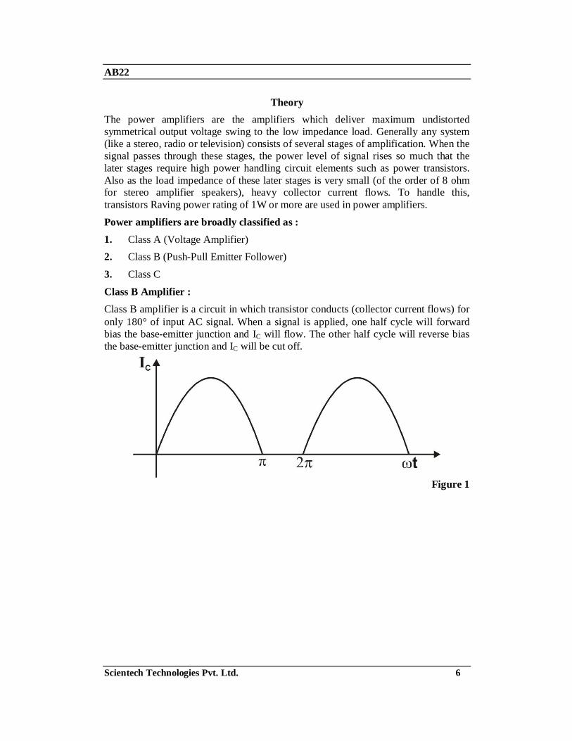
Class B Amplifier : Class B amplifier is a circuit in which transistor conducts (collector current flows) for only 180° of input AC signal. When a signal is applied, one half cycle will forward bias the base-emitter junction and IC will flow. The other half cycle will reverse bias the base-emitter junction and IC will be cut off.
Figure 1

AB22
Scientech Technologies Pvt. Ltd. 7
For class B amplifiers the Q point is located near the cutoff point of the AC load line. Thus, to amplify entire input AC signal a combination of two Class - B amplifiers are used. One of which amplifies positive half cycle of input AC signal and the other amplifies negative half cycle of input AC signal. This amplifier configuration is known as push-pull or complementary symmetry. In the push-pull configuration it is important to match the two transistors carefully for the proper amplification of both the halves. While the input signal being amplified through class B amplifier the input signal has to rise to about 0.7V to overcome the barrier potential of amplifying transistor. During this period no current flows through the circuit and output is zero. The action is similar for both the transistors. Thus, following characteristic is obtained for input and output voltages:
Figure 2
The output signal no longer remains sine wave and gets distorted. Since the clipping occurs between the time when one transistor cuts off and at the time when other one comes on. We call it crossover distortion.

AB22
Scientech Technologies Pvt. Ltd. 8
Input and output waveforms illustrating the zone/crossover distortion
Figure 3
To remove the crossover distortion a slight forward bias is applied to each emitter diode i.e. we locate the Q point of both the transistors slightly above the cutoff. Thus collector current in both the transistors flows for more than 180° but less than 360°. Sometimes we call such an amplifier as Class AB amplifier.
Figure 4

AB22
Scientech Technologies Pvt. Ltd. 9
Operating parameters of Class B Amplifier : Voltage Gain : It is the ratio of output voltage (Vout) obtained to input voltage (Vin).
Av = Vout / Vin
Figure 5
Input Impedance : It is the ratio of Input voltage (Vin) to Input Current (Ii).
Zin = Vin / Ii
To measure the input impedance a known resistor (Rs) is placed in series before the input coupling capacitor and the impedance could be calculated using the equation.
Zin = RS / [AV / (AV'-I)]
Where, AV = voltage gain without the resistor (RS) AV' = voltage gain with the resistor (RS)
Output Impedance : It is the ratio of Output Voltage (Vout) to Output Current (IO).
Zout = Vout / Io To measure the output impedance a known resistor (RS) is placed from output to ground and the output impedance could be calculated using the equation.
Zout = [AV / (AV'-I)] * RS
Where, AV = voltage gain without the resistor (RS) AV' = voltage gain with the resistor (RS)
Current gain : It is the ratio of output current (Io) to Input current (Ii).
Ai = Io / Ii
The Current gain could be calculated using the equation
Ai = -AV * Zin / RL

AB22
Scientech Technologies Pvt. Ltd. 10
Power Gain : It is the ratio of output AC power (Po) to input AC power (Pi).
PO = Vo(P-P)2 / (8 * RL) = Vrms
2 / RL Pi = Vin (p-p)
2 / (8 * Zin) = Vin(rms)
2 / Zin
The Power Gain can be calculated using the equation
Ap = Po / Pi

AB22
Scientech Technologies Pvt. Ltd. 11
Experiment Objective : Study of the operation of Class B Amplifier Equipments Needed : 1. Analog board of AB22 2. Variable DC power supplies +5V and -5V from external source or ST2612
Analog Lab 3. Function Generator
4. Oscilloscope Caddo 802 or equivalent
Circuit diagram : Circuit used to show the Class B Amplifier operation is as shown below :
Figure 6

AB22
Scientech Technologies Pvt. Ltd. 12
Procedure :
• Connect +5V and -5V DC power supplies at their indicated position from external source or ST2612 Analog Lab.
• Connect 2Vp-p AC signal (1 KHz) at the Vin input of the AB22. 1. Put the potentiometer P1 to its minimum position i.e. rotate it fully
anticlockwise. (This is the condition when no bias voltage is applied to the emitter diodes of both the transistors.)
2. Connect Oscilloscope at the output terminals of AB22 and observe the output waveform. The crossover distortion can be clearly observed on the oscilloscope.
3. Gradually increase the bias voltage by increasing bias resistance (i.e. rotate the potentiometer in clockwise direction) up to the value when the crossover distortion is completely removed and maximum amplification of the input signal is obtained.
4. Connect the input AC signal to the Class B amplifier through 100 ohms series resistance.
5. Measure the input and output voltage amplitude and also input and output impedance as described earlier.
6. Measure the power gain of class B amplifier using the operating parameters as described in class B theory.
Results : Input AC Voltage Amplitude (Vin) : .........Vp-p Input Impedance (Zin) : ..........................Ohms
Input Current (Ii) : ....................................... A
Output AC Voltage Amplitude (Vout) : .....Vp-p
Output Impedance (RL) : ....................... ohms Output Current (Io) : .................................... A
Power Gain (Ap) : ...........................................

AB22
Scientech Technologies Pvt. Ltd. 13
Data Sheet

AB22
Scientech Technologies Pvt. Ltd. 14

AB22
Scientech Technologies Pvt. Ltd. 15
Warranty 1. We guarantee the product against all manufacturing defects for 24 months from
the date of sale by us or through our dealers. Consumables like dry cell etc. are not covered under warranty.
2. The guarantee will become void, if
a) The product is not operated as per the instruction given in the operating manual.
b) The agreed payment terms and other conditions of sale are not followed.
c) The customer resells the instrument to another party. d) Any attempt is made to service and modify the instrument.
3. The non-working of the product is to be communicated to us immediately giving full details of the complaints and defects noticed specifically mentioning the type, serial number of the product and date of purchase etc.
4. The repair work will be carried out, provided the product is dispatched securely packed and insured. The transportation charges shall be borne by the customer.
For any Technical Problem Please Contact us at [email protected]
List of Accessories
1. 2 mm Patch Cords 8” (Red) .................................................................. 2 Nos. 2. 2 mm Patch Cord 8” (Black) ................................................................. 3 Nos.
3. 2 mm Patch Cord 8” (Blue) .................................................................. 2 Nos. 4. e-Manual.................................................................................................1 No.
Updated 24-03-2009