ab-23 class c tuned amplifier · ab-23 class c tuned amplifier ab-23 table of contents...
TRANSCRIPT
AB-23CLASS C TUNED AMPLIFIER
ANALOG LAB
EXPERIMENT BOARD
Ver. 1.0
An ISO 9001: 2000 company
AB-23
94-101, Electronic Complex, Pardesipura INDORE-452010, India.Tel.: 91-731-2570301 Fax: 91-731-2555643Email: [email protected] Web: www.scientech.bz
Scientech Technologies Pvt. Ltd. 2
AB-23
CLASS C TUNED AMPLIFIERAB-23
TABLE OF CONTENTS
1.Introduction 3
2. Theory 5
3.Experiment 1 To study the operation of Class C Tuned Amplifier. 9
4.Datasheet 12
5.Warranty 14
6.List of Service Centers 15
7.List of Accessories with AB-23 16
Scientech Technologies Pvt. Ltd. 3

AB-23
INTRODUCTION
AB-23 is a compact, ready to use CLASS C TUNED AMPLIFIER experiment board. This board along with AB-21 and AB-22 boards is useful for students to understand the working and operation of various power amplifier categories. It can be used as stand alone unit with external DC power supply or can be used with SCIENTECH ANALOG LAB ST-2612 which has built in DC power supply, AC power supply, function generator, modulation generator, continuity tester, toggle switches and potentiometer.
List of Boards :
Model Name
AB-01AB-02AB-03AB-04AB-05AB-06AB-07AB-08AB-15AB-16AB-17AB-18AB-21AB-22AB-26
AB-28AB-29AB-30AB-31AB-32 AB-33 AB-41AB-42
AB-43
Diode characteristics (Si, Zener, LED)Transistor characteristics (CB NPN)Transistor characteristics (CB PNP)Transistor characteristics (CE NPN)Transistor characteristics (CE PNP)Transistor characteristics (CC NPN)Transistor characteristics (CC PNP)FET characteristicsCommon Emitter AmplifierCommon Collector AmplifierCommon Base AmplifierR-C Coupled AmplifierClass A AmplifierClass B Amplifier (push pull emitter follower)Phase Locked Loop (FM Demodulator & Frequency Multiplier)Multivibrators (Astable / Monostable)F-V and V-F ConverterV-I and I-V ConverterZener Voltage Regulator Transistor Series Voltage RegulatorTransistor Shunt Voltage RegulatorDifferential Amplifier (Transistorized)Operational Amplifier (Inverting / Non-inverting / Differentiator)Operational Amplifier (Adder/Scalar)
Scientech Technologies Pvt. Ltd. 4
AB-23
AB-44
AB-45AB-51AB-52AB-53AB-56AB-65
AB-66
AB-67
AB-81
AB-82
AB-83
AB-84
AB-90AB-91AB-92AB-93
Operational Amplifier (Integrator/ Differentiator)Schmitt Trigger and ComparatorActive filters (Low Pass and High Pass)Active Band Pass Filter Notch Filter Fiber Optic Analog LinkPhase Shift OscillatorWien Bridge OscillatorColpitt OscillatorKirchoff’s Laws (Kirchoff’s Current Law & Kirchoff’s Voltage Law)Thevenin’s and Maximum power Transfer TheoremReciprocity and Superposition TheoremTellegen’s TheoremTwo port network parameterOptical Transducer (Photovoltaic cell)Optical Transducer(Photoconductive cell/LDR)Optical Transducer (PhotoTransistor)
…and many more
Scientech Technologies Pvt. Ltd. 5

AB-23
THEORY
The power amplifiers are the amplifiers which deliver maximum undistorted symmetrical output voltage swing to the low impedance load. Generally any system (like a stereo, radio or television) consists of several stages of amplification. When the signal passes through these stages, the power level of signal rises so much that the later stages require high power handling circuit elements such as power transistors. Also as the load impedance of these later stages is very small (of the order of 8 ohm for stereo amplifier speakers), heavy collector current flows. To handle this, transistors heaving power rating of 1W or more are used in power amplifiers.
Power amplifiers are broadly classified as :
1. Class A (Voltage Amplifier)
2. Class B (Push-Pull Emitter Follower)
3. Class C Tuned Amplifier
Class C Tuned Amplifier :
Class C amplifier is a power amplifier in which collector current of the amplifying transistor flows for less than 180° of input AC signal.
Fig. 1
Scientech Technologies Pvt. Ltd. 6

AB-23
In short a class C amplifier is one in which the operating point is chosen so that the output current (or voltage) is zero for more than one half of an input sinusoidal signal. The output signal would be distorted if this non-sinusoidal current flows through the resistive load. To avoid the distortion that would occur due to purely resistive load, load is usually a resonant tank circuit (LC circuit), which therefore has a high resistive value at the frequency of interest. Hence, the selected signal output is free from non-linear distortions. The resonant tank circuit is tuned to the frequency of input signal. When the circuit has a high quality factor (Q), parallel resonance occurs at approximately.
Where,
L = inductance
C = capacitance
The AC equivalent circuit of base-emitter junction is as shown in Fig.2 when Q of the circuit is high enough.
Fig.2
Scientech Technologies Pvt. Ltd. 7
AB-23
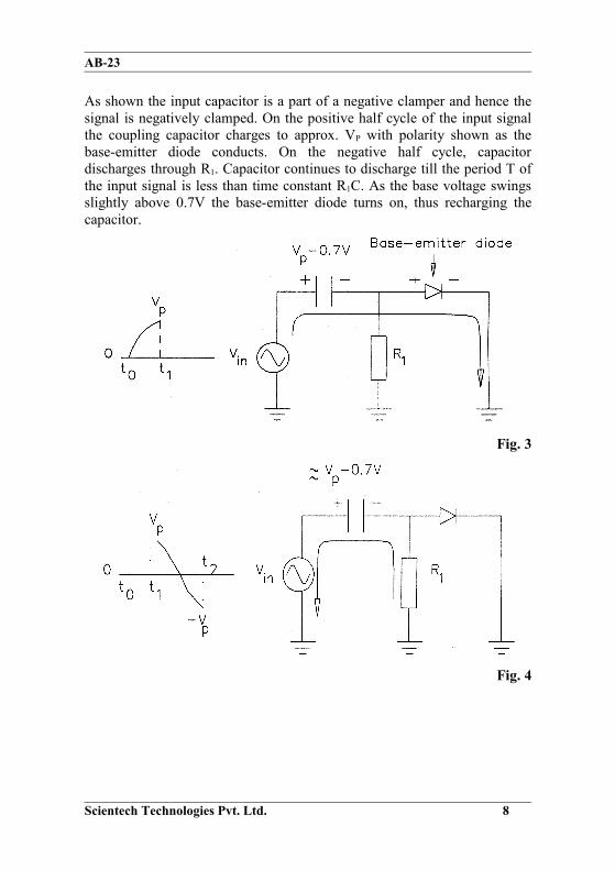
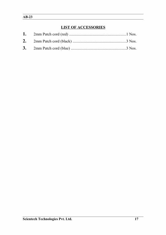
As shown the input capacitor is a part of a negative clamper and hence the signal is negatively clamped. On the positive half cycle of the input signal the coupling capacitor charges to approx. VP with polarity shown as the base-emitter diode conducts. On the negative half cycle, capacitor discharges through R1. Capacitor continues to discharge till the period T of the input signal is less than time constant R1C. As the base voltage swings slightly above 0.7V the base-emitter diode turns on, thus recharging the capacitor.
Fig. 3
Fig. 4
Scientech Technologies Pvt. Ltd. 8

AB-23
At the output side the collector current source drives a parallel resonant tank circuit. At resonance, the AC load impedance is purely resistive and the collector current is minimum and the peak-to-peak load voltage reaches a maximum. Above and below the resonance, AC load impedance decreases and the collector current increases, thus reducing the amplification level or introducing distortion in the output signal. A class C amplifier is a narrowband circuit it amplifies only the signals of resonant frequency and near to it. As the amplification level reduces when input frequency is moved up and down the resonant frequency, we can find out the bandwidth of the amplifier. The bandwidth of the Class C amplifier can be find out as follows,
BW = FH - FL
Where,
FH = upper half power frequency
FL = lower half power frequency
The half power frequencies are identical frequencies at which the voltage gain equals 0.707 times the maximum gain. The smaller the difference, narrower is the bandwidth of amplifier.
The dc collector current depends on the conduction angle and hence the overall efficiency of the amplifier. In short as the duty cycle increases the efficiency of the amplifier decreases. For the conduction angle of 180° the amplifier efficiency is 78.5%. If we further reduce the conduction angle the stage efficiency will increase. The class C amplifier efficiency can be 100% at the maximum.
The following formulas are used for Class C Tuned Amplifier,
1. Input AC Power, Pi(ac) = Vp-p2 / 8 * Rs (Rs = Input impedance)
2. Output AC Power, Po(ac) = Vp-p2 / 8 * RL (RL= Output impedance)
3. Power Gain, Ap = Po(ac) / Pi(ac)
4. Input DC Power, Pi(dc) = Vcc * Idc (Idc = Input DC Current)
5. Efficiency, n% = Po(ac) * 100/ Pi(dc)
Scientech Technologies Pvt. Ltd. 9

AB-23
EXPERIMENT 1
Object :
To study the operation of Class C Tuned Amplifier.
Apparatus Required:
1. Analog board of AB-23.
2. Variable DC power supply +12V from external source or ST-2612 Analog Lab.
3. Function Generator from external source or ST-2612 Analog Lab.
4. Oscilloscope.5. Ammeter.
6. 2 mm. patch cords.
Circuit Diagram :
Circuit used to study the operation of Class C Tuned Amplifier is shown below
Fig. 5
Scientech Technologies Pvt. Ltd. 10

AB-23
Procedure :
• Connect + 12V DC power supply at their indicated position from external source or ST-2612 Analog Lab.
• Connect 2Vp-p AC signal (10 KHz and above) at the Vin input of the AB- 23 board.
1. Connect Oscilloscope at the output terminals of AB-23 and observer the output waveform.
2. Connect ammeter between the points a and b.
3. Gradually increase the input signal frequency up to the value till the maximum undistorted amplified output is obtained.
4. Vary the pot such that the output voltage amplitude increases. Adjust the pot to get maximum undistorted (unclipped) output voltage.
5. Note the frequency at which this amplification is obtained and check it against the theoretically calculated resonant frequency calculated using Eq. l.
6. Observe the conduction angle at the test point TP1 on AB-23 board.
7. Calculate the peak-to peak value of the output signal.
8. Observe the output voltage level above and below to resonant frequency by varying input frequency from 5 KHz to 100 KHz.
9. Carryout the following calculations.
10. Apply +15V or +10V to the input bias voltage instead of +12V and observer the changes in the output voltage.
Results :
Input AC signal amplitude (Vin) : ........................................... Vp-p
Output AC signal amplitude (Vout) :........................................ Vp-p
Resonant Frequency (Fr) : (Practical value) : ........................ Hz
Resonant Frequency (fr) : (Theoretical value) : .....................Hz (From Eq.l)
Input AC Power (Pi(ac) = Vp-p2 /8 * Rs) : ..................................W.
Output AC Power (Po(ac) = Vp-p2 / 8 * RL):...............................W.
Scientech Technologies Pvt. Ltd. 11

AB-23
Power Gain (Ap = Po(ac) / Pi(ac)) : ............................................
Input DC power (Pi(dc) = Vcc * Idc) : ...................................... W(Note: To calculating DC power, switch off the AC signal and now read the ammeter for DC current Idc)
Efficiency (n % = Po(ac) * 100 / Pi(dc)) : .................................. %
3dB voltage (Vout (max) - ( Vout (max) * 0.707)) :............................. Vp-p
Higher Cutoff Frequency (FH) :.............................................. Hz
Lower Cutoff Frequency (FL) :............................................... Hz
Bandwidth (BW = FH - FL) :....................................................
Carry out the same calculations after applying +15V and +10V and observe the changes.
Scientech Technologies Pvt. Ltd. 12

AB-23
DATASHEET
Scientech Technologies Pvt. Ltd. 13

AB-23
Scientech Technologies Pvt. Ltd. 14

AB-23
WARRANTY
1) We guarantee the instrument against all manufacturing defects during 24 months from the date of sale by us or through our dealers.
2) The guarantee covers manufacturing defects in respect of indigenous components and material limited to the warranty extended to us by the original manufacturer, and defect will be rectified as far as lies within our control.
3) The guarantee will become INVALID.a) If the instrument is not operated as per instruction given in the
instruction manual. b) If the agreed payment terms and other conditions of sale are not
followed.c) If the customer resells the instrument to another party.d) Provided no attempt have been made to service and modify the
instrument.
4) The non-working of the instrument is to be communicated to us immediately giving full details of the complaints and defects noticed specifically mentioning the type and sr. no. of the instrument, date of purchase etc.
5) The repair work will be carried out, provided the instrument is dispatched securely packed and insured with the railways. To and fro charges will be to the account of the customer.
DESPATCH PROCEDURE FOR SERVICE
Should it become necessary to send back the instrument to factory please observe the following procedure:
1) Before dispatching the instrument please write to us giving full details of the fault noticed.
2) After receipt of your letter our repairs dept. will advise you whether it is necessary to send the instrument back to us for repairs or the adjustment is possible in your premises.
Dispatch the instrument (only on the receipt of our advice) securely packed in original packing duly insured and freight paid along with accessories and a copy of the details noticed to us at our factory address.
Scientech Technologies Pvt. Ltd. 15

AB-23
LIST OF SERVICE CENTERS
1. Scientech Technologies P. Ltd.90, Electronic Complex Ph: (0731) 5202959Pardesipura, Email: [email protected] INDORE – 452010
2. Scientech Technologies P. Ltd.First Floor, Ph.: (011) 26513912, 2686494314, Uday Park, Fax: (011) 26864943.NEW DELHI – 110049 Email: [email protected]
3. Scientech Technologies P. Ltd.New no.2, Old no.10, 4th street Ph.: (044) 52187548, 52187549
Venkateswara nagar, Adyar Fax: (044) 52187549CHENNAI – 600025 Email: [email protected]
4. Scientech Technologies P. Ltd. 202/19, 4th main street Ph.: (080) 51285011 Ganganagar, Fax: (080) 51285022 BANGALORE- 560032 Email: [email protected]. Scientech Technologies P. Ltd. First floor, L block Ph.: (022) 56299547 Ranjit studio compound, Fax: (022) 24155984 Dada Saheb Phalke road, Email: [email protected] Dadar (East) MUMBAI – 4000146. Scientech Technologies P. Ltd. 988, Sadashiv Peth, Ph.: (020) 24461673 Gyan Prabodhini Lane, Fax: (020) 24482403 PUNE – 411030 Email: [email protected]. Scientech Technologies P. Ltd 4, Balaji Nagar Mobile: 98231-94992 Hingna Road, E mail: [email protected]
Opp. N.N.S. Bank Ltd. NAGPUR- 440016
Scientech Technologies Pvt. Ltd. 16
AB-23
LIST OF ACCESSORIES
1. 2mm Patch cord (red) .........................................................1 Nos.
2. 2mm Patch cord (black) ......................................................3 Nos.
3. 2mm Patch cord (blue) ........................................................3 Nos.
Scientech Technologies Pvt. Ltd. 17