aas14-414 safe release of a picosatellite from … · safe release of a picosatellite from a small...
TRANSCRIPT

AAS 14-414
SAFE RELEASE OF A PICOSATELLITE FROM A SMALLSATELLITE CARRIER IN LOW EARTH ORBIT
Martin Wermuth∗, Gabriella Gaias†, and Simone D’Amico‡
The BIROS satellite, which is scheduled for launch in 2015 into a low Earth or-bit, will carry onboard a picosatellite and subsequently release it through a springmechanism with a fixed velocity. In the frame of the AVANTI experiment, theBIROS satellite will perform proximity maneuvers in a mid-range formation withthe picosatellite, based solely on optical navigation through its onboard camera.Therefore it is necessary to keep the relative distance of the two spacecraft withincertain limits. This is contradicted by the fact, that the spring mechanism is de-signed to create a large and safe separation between the two spacecraft.
In this paper a maneuver strategy is developed in the framework of relative or-bital elements. The goal is to avoid any risk of collision on one side and to mitigatethe possibility of formation evaporation on the other side. Main design drivers areseveral uncertainties - most prominently the performance uncertainty of the releasemechanism. The analyzed strategy consists of two maneuvers: the separation it-self and a drift reduction maneuver of the BIROS satellite after 1.5 revolutions.Afterwards a third maneuver is to be performed to minimize the residual drift,estimated through an orbit determination with radar tracking.
The selected maneuver parameters are validated in a Monte Carlo simulation.It is demonstrated that the risk of formation evaporation is below 0.1% as wellas the eventuality of a residual drift towards the carrier. In the latter case forma-tion safety is guaranteed by a passive safety achieved through a proper relativeeccentricity/inclination vector separation.
INTRODUCTION
This paper addresses the design of a safe strategy to inject a picosatellite in low Earth orbitafter separation from a small satellite carrier. The problem is motivated by the Autonomous VisionApproach Navigation and Target Identification (AVANTI) experiment onboard the Berlin InfraRedOptical System (BIROS1) spacecraft.
In the recent years, the deployment of small-scale satellites as secondary payloads into low Earthorbit has become more and more common.2, 3, 4, 5 To this trend contributed both the miniaturizationof the technology and the increase in number of educational scientific programs. Within these ap-plications, the launcher vehicles are typically equipped by spring-based deployment devices whichprovide a linear velocity relative to the carrier that ranges from 0.3 to 2.0 m/s.6 Since the main pur-pose of these technology demonstrations is focused on the ejected elements, the separation phase
∗Research Engineer, German Space Operations Center (GSOC/DLR), Oberpfaffenhofen , 82234 Wessling, Germany.†Research Engineer, German Space Operations Center (GSOC/DLR), Oberpfaffenhofen , 82234 Wessling, Germany.‡Assistant Professor, Department of Aeronautics & Astronautics, Stanford University, Durand Building, Stanford, CA94305, USA.
1
has to quickly and safely establish a certain relative distance, disregarding how different the finaldynamics of the two vehicles are. Therefore, the ejection can be simply achieved by imparting thedeployment delta-v in flight direction, in the verse dictated by the differential drag effect.
In 2010, in the frame of the Prototype Research Instruments and Space Mission technology Ad-vancement (PRISMA7) mission, a different application scenario was successfully demonstrated inflight. It involved the separation of two satellites with the aim of performing some formation flyingactivities. The employed separation mechanism, a 3-point system with hooks and clamps kept inlocked position by a single wire, was meant to provide a small delta-v (i.e., nominally 0.12 m/s).8
Moreover, the accuracy of its true performance allowed considering safe relative orbits that inter-sect the local carrier horizon plane at an along-track separation of the order of 150 m. A furtherpeculiarity of this satellite separation resided in the availability of a GPS-receiver on each satelliteand of an inter-satellite link. Thus, the differential GPS relative navigation could be used to estimateboth the deployment delta-v and the residual drift at the end of the separation phase.
The problem we are dealing with, presents commonalities with both these above mentioned cate-gories of applications. On one hand, the BIROS spacecraft makes use of a spring-based PicosatelliteOrbit Deployer (POD) device that provides a large and strongly uncertain separation delta-v. On theother hand, the picosatellite release serves the sake of the AVANTI experiment, where a noncoop-erative target (i.e., the ejected picosatellite) is the object of several formation flying activities.The major challenges of our application stem from the fact that a safe and stable relative motion ofthe formation has to be established shortly after separation subject to several operational constraints.Nevertheless, the results of this paper allow the extension and generalization of the relative eccen-tricity/inclination vector separation method9 to a new class of distributed space systems. Overallthis work proposes an effective way to solve a mission specific problem which might have relevantapplications in future on-orbit servicing and distributed space systems architectures.
The proposed and analyzed guidance and maneuver planning approach is based on the relativeeccentricity/inclination vector separation method which was first introduced for the collocation ofgeostationary satellites,10 later applied for long-range rendezvous in low Earth orbits,11 and finallyextended to formation-flying12 and on-orbit servicing scenarios.13 Indeed a safe passively stablerelative motion can be established after the release of a picosatellite from a satellite carrier by en-suring the (anti-) parallelism of the relative eccentricity and inclination vectors.A further novelty of the proposed approach is to investigate, at a design level, how additional rele-vant operational aspects impact the safety and the feasibility of the guidance plan. Specifically, ourstudy addresses also the distance of the nearest transit of the picosatellite through the local along-track axis, the eventual delay and/or mis-execution of the drift-stopping maneuver, and, finally, theachievement of a final relative drift with known and safe direction, regardless of the uncertainties inthe whole control chain.In order to deal with such a comprehensive scenario while establishing a desired passively safe sta-ble relative orbit, the preliminary design of the maneuvering strategy is carried out in the RelativeOrbital Elements (ROE) framework.14 These parameters, in fact, are the integration constants ofthe Hill-Clohessy-Wiltshire equations and provide a direct insight into the geometry and thus intothe safety characteristics of the relative motion. By making use of the simple relations betweenchanges in ROE and applied delta-v derived from the inversion of the model of relative dynamics,a nominal scheme of maneuvers to accomplish the separation can be designed. Specifically it canbe shown that a single maneuver cannot establish the parallelism of the relative eccentricity andinclination vectors, within the operational constraints of the application under consideration. A
2
double-maneuver strategy, on the contrary, can accomplish this task, leaving as degrees of freedomthe tuning of certain parameters related to the size and mean along-track separation of the finalrelative orbit and to the satisfaction of the aforementioned feasibility aspects.
The ultimate validation of the preliminary designed guidance scheme is accomplished throughmultiple numerical analyses. These take into account several sources of uncertainty which affectthe reliability of the nominal plan: the POD delta-v magnitude error due to the spring release mech-anism, the BIROS attitude control error, the BIROS maneuver execution error, and the uncertaintyin the knowledge of the differential ballistic coefficients. Taking all these uncertainties into accountit is obvious, that after the second maneuver a residual drift will remain, though in the safe directionprescribed by the preliminary design. Therefore, in order to achieve a stable formation for the startof the AVANTI experiment, an orbit determination of the picosatellite has to be performed and athird maneuver has to be executed to stop the residual drift.
In the following, first an overview of the mission with its requirements is provided. Secondly, thepreliminary design of the guidance plan is described and a baseline scenario compliant with all therelevant operational aspects is selected. Finally, the results of some nonlinear Monte Carlo (MC)simulations are presented and discussed, in the attempt to demonstrate the safety and efficiency ofthe overall methodology.
MISSION OVERVIEW AND REQUIREMENTS
Scheduled for launch in 2015 the BIROS satellite (60x80x80 cm, 140 kg) will be operated bythe German Aerospace Center (DLR). Its primary task next to several technology demonstrationexperiments (including AVANTI) will be the observation of wildfires in the frame of the FireBirdmission. Together with the similar TET-1 satellite, which was launched in 2012 and is operated byDLR as well, it will form a loose constellation of Earth observation satellites. BIROS is designatedfor injection into a sun-synchronous orbit with 9:30 LTAN at an orbit height of 515 km. Thespacecraft is equipped with a propulsion system and a fuel availability corresponding to circa 20m/s of delta-v. Half of the fuel is allocated to the AVANTI Experiment, while the other half isallocated for the primary mission objective.
The AVANTI experiment is intended to demonstrate vision-based noncooperative autonomousapproaches and recedes operations of an active small satellite (BIROS) within separations between10 km and 100 m from a picosatellite (10x10x10 cm, 1kg) making use of angles-only measurements.The picosatellite is originally carried by BIROS and later on ejected through a POD deployer af-ter the successful check-out and commissioning of all relevant BIROS subsystems. The AVANTIexperiment is intended to start after that the BIROS/Picosatellite formation has been brought to aninitial safe configuration at about 5 km separation with minimal residual drift in along-track direc-tion. This delicate operational task is solely ground-based and performed by the Flight DynamicsServices (FDS) division of the German Space Operations Center (GSOC), which is in charge of theorbit determination and control of the FireBird mission.
The mission profile is characterized by several external constraints which have to be consideredduring the analysis of a safe separation. First of all the separation must take place during a ground-station contact, which poses restrictions on the location of the deployment along the orbit and onthe separation attitude for proper communication. The size of the delta-v imparted at injection isfixed to 1.41 m/s. If oriented in along-track direction, this corresponds to about 2.8 km semi-majoraxis difference between the BIROS and picosatellite orbits, which produces an along-track drift of
3

27 km/orbit or 405 km/day. Since the only means of navigation information for the picosatellite isradar tracking from ground, with associated latencies of typically 24 hours, the risk of formationevaporation would be too high when adopting this conventional separation strategy. Nevertheless,due to all the uncertainties that characterize the whole separation and control chain, a certain residualdrift towards evaporation remains also when employing the guidance scheme proposed here. Theradar tracking facility foreseen within the FireBird mission is the imaging radar (TIRA) station inGermany.15 According to it, due to the different sizes of the BIROS satellite and the picosatellite,a minimum distance of 5 km is required for TIRA to be able to distinguish the signal from the twospacecraft. Typically two tracking passes with a spacing of 12 hours are necessary for an accurateorbit determination.
Additional geometrical constraints are introduced by the camera employed by the AVANTI exper-iment. The experience from previous missions16 suggests, that the camera should be able to detectthe picosatellite up to a distance of 10 km. The half field of view of the camera is 6.8 horizontallyand 9.15 vertically. The separation scenario must ensure the visibility of the picosatellite at thestart of the AVANTI experiment.
RELATIVE MOTION DESCRIPTION
The relative motion is parameterized by this set of dimensionless relative orbital elements (ROE):
δα =
δaδλδexδeyδixδiy
=
δaδλ
δe cosϕδe sinϕδi cos θδi sin θ
=
(a− ad)/adu− ud + (Ω− Ωd) cos id
e cosω − ed cosωde sinω − ed sinωd
i− id(Ω− Ωd) sin id
(1)
where a, e, i, Ω, and M denote the classical Keplerian elements and u = M + ω is the meanargument of latitude.∗ The subscript ”d” labels the deputy spacecraft of the formation, which playsthe role of the maneuverable carrier satellite (BIROS) and defines the origin of the local radial-tangential-normal (RTN) frame. Hereinafter, the magnitudes of the dimensionless relative eccen-tricity and inclination vectors are shortly quoted as ‖δe‖ = δe and ‖δi‖ = δi respectively, whereasthe subscript is dropped, meaning that all the absolute orbital quantities appearing in the equationsbelong to the servicer satellite.Under the assumptions of the Hill-Clohessy-Wilshire equations (HCW),17 the quantities aδe andaδi provide the amplitudes of the in-plane and out-of-plane relative motion oscillations, whereasrelative semi-major axis, aδa, and relative mean longitude, aδλ = a(δu+ δiy cot i), provide meanoffsets in radial and along-track directions respectively.9, 18
According to the model of the relative dynamics just introduced, the instantaneous dimensionalvariations of the ROE caused by an impulsive maneuver (or an instantaneous velocity change) at
∗A section on mathematical notation is provided in the appendix.
4
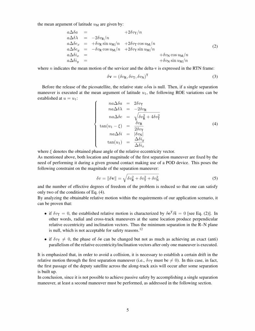
the mean argument of latitude uM are given by:
a∆δa = +2δvT/na∆δλ = −2δvR/na∆δex = +δvR sinuM/n +2δvT cosuM/na∆δey = −δvR cosuM/n +2δvT sinuM/na∆δix = +δvN cosuM/na∆δiy = +δvN sinuM/n
(2)
where n indicates the mean motion of the servicer and the delta-v is expressed in the RTN frame:
δv = (δvR, δvT, δvN)T (3)
Before the release of the picosatellite, the relative state aδα is null. Then, if a single separationmaneuver is executed at the mean argument of latitude u1, the following ROE variations can beestablished at u = u1:
na∆δa = 2δvTna∆δλ = −2δvR
na∆δe =√δv2
R + 4δv2T
tan(u1 − ξ) =δvR
2δvTna∆δi = |δvN|
tan(u1) =∆δiy∆δix
(4)
where ξ denotes the obtained phase angle of the relative eccentricity vector.As mentioned above, both location and magnitude of the first separation maneuver are fixed by theneed of performing it during a given ground contact making use of a POD device. This poses thefollowing constraint on the magnitude of the separation maneuver:
δv = ‖δv‖ =√δv2
R + δv2T + δv2
N (5)
and the number of effective degrees of freedom of the problem is reduced so that one can satisfyonly two of the conditions of Eq. (4).By analyzing the obtainable relative motion within the requirements of our application scenario, itcan be proven that:
• if δvT = 0, the established relative motion is characterized by δeTδi = 0 [see Eq. (2)]. Inother words, radial and cross-track maneuvers at the same location produce perpendicularrelative eccentricity and inclination vectors. Thus the minimum separation in the R–N planeis null, which is not acceptable for safety reasons.12
• if δvT 6= 0, the phase of δe can be changed but not as much as achieving an exact (anti)parallelism of the relative eccentricity/inclination vectors after only one maneuver is executed.
It is emphasized that, in order to avoid a collision, it is necessary to establish a certain drift in therelative motion through the first separation maneuver (i.e., δvT must be 6= 0). In this case, in fact,the first passage of the deputy satellite across the along-track axis will occur after some separationis built up.In conclusion, since it is not possible to achieve passive safety by accomplishing a single separationmaneuver, at least a second maneuver must be performed, as addressed in the following section.
5

Separation preliminary design: the double-maneuver scheme
The analytical form of the general expression of the in-plane double-pulse maneuvers’ scheme,for whatever aimed final conditions, as function of the mean arguments of latitude of the two ma-neuvers is given in Eq.(15) of Reference 14. Nevertheless, this expression is quite complicated anddoes not allow an immediate geometrical insight into the geometry of the relative motion. To thisaim, at a preliminary stage, we can use Eq.(2.42) of Reference 9:
δvR1 = na2 ( −∆δλ∗
2 +∆δe sin(u1 − ξ) ) − na2 κ ( ∆δa −∆δe cos(u1 − ξ) )
δvT1 = na4 ( +∆δa +∆δe cos(u1 − ξ) ) − na
4 κ ( ∆δλ∗
2 +∆δe sin(u1 − ξ) )
δvR2 = na2 ( −∆δλ∗
2 −∆δe sin(u1 − ξ) ) + na2 κ ( ∆δa −∆δe cos(u1 − ξ) )
δvT2 = na4 ( +∆δa −∆δe cos(u1 − ξ) ) + na
2 κ ( ∆δλ∗
2 +∆δe sin(u1 − ξ) )
(6)
with
κ =sin ∆u
cos ∆u− 1∆u = u2 − u1 ξ = arctan
(∆δey∆δex
)(7)
As mentioned in the previous section, since the initial relative state is null, the total aimed variationcoincides with the final aimed relative state:
∆δ• = δ •F and ϕF = ξ (8)
Equation (6) provides an analytical expression of the double-impulse in-plane scheme to achievea prescribed total variation of ∆δa, ∆δe, and ∆δλ∗. It embodies a simplification of the ones inReference 14, since it does not involve the relationship between δλ and δa, leading to the quantity∆δλ∗ instead of the truly obtainable ∆δλ. However this is acceptable at a preliminary stage, andallows achieving a much simpler expression of the in-plane delta-vs.
When dealing with the in-orbit release of a satellite, Eq. (6) must be complemented with the out-of-plane equations. The passive safety constraint of final (anti)parallelism of the relative e/i vectors,in fact, couples back to the impulsive reconfiguration problem.In the following, the remaining specific requirements of the separation problem are listed and dis-cussed, together with their geometrical interpretation in the ROE space. In Figure 1 all the finaldesired quantities, which are the parameters that appear in Eq. (6) are marked in black. The otherquantities represent the intermediate values obtained during the execution of a double-impulse ma-neuvering scheme.
The following features characterize our application scenario:
• The location of the first maneuver u1 is fixed and known, since the deployment has to occurduring a ground contact. Consequently, the phase of the relative inclination vector after thefirst maneuver θ is also fixed (i.e., dotted light gray segment in the δi plane ): u = u1 = θF.
• In order to achieve passive safety, we must impose the phase of the final δe, ξ to be equal toθF (i.e., dotted light gray segment in the first quadrant of δe plane), or to θF + π (i.e., thirdquadrant). Thus, in a general case, we can impose ξ = θF + η, where the service parameter ηcan only assume the values of 0 or π
• Our aim is to establish a final stable relative orbit, thus δaF = 0. This implies that all termsin ∆δa in Eq. (6) vanish.
6

iy
ix
i1
ey
exe0
e = eF
1u = F
e1
e2
i0
2
Figure 1. Sketch in the ROE space of the maneuvering scheme of Eq. (6) to achieve passive safety
• Equation (6) is defined for ∆u 6= 0 or 6= 2π. In all other cases, κ weights the effect of themaneuvers’ spacing on the final four in-plane delta-v expressions. In the special case of κ oddnumber and ∆u = κπ the second part of Eq. (6) vanishes. As a result the delta-v expressionsare characterized by a symmetrical form. Moreover, in these particular locations of the secondmaneuver, the effect of the second out-of-plane maneuver can only change the magnitude ofδi, and not the phase θF, whenever δvN2 is nonzero. This is marked by the gray arrows in theleft side of Figure 1.
• As already mentioned, the first maneuver is accomplished by the deployment device, thus itsmagnitude is constrained to δv. This introduces a relationship on the three RTN components,and, consequently on the achievable ∆δe, ∆δλ∗, and ∆δi.
By taking into account the aforementioned requirements, the delta-v expressions of Eq. (6) sim-plify to:
δvR1 = −na4 ( ∆δλ∗ )
δvT1 = ±na4 ( ∆δe )
δvR2 = −na4 ( ∆δλ∗ )
δvT2 = ∓na4 ( ∆δe )
(9)
since u1 = ξ. The signs of Eq. (9) are determined by fixing η (i.e., the final δe/δi configuration)and by the sign of ∆δλ∗ (i.e., picosatellite leading or following the carrier).
Referring to Eq. (9), the remaining degrees of freedom of the separation problem are: two amongthe three aimed magnitudes δeF, δiF and δλ∗F together with the spacing between the maneuvers (i.e.,the number of half revolutions κ). These parameters are fixed as soon as an aimed final orbit isidentified. Therefore, the next section deals with the identification of such a nominal baseline, inorder to cope with some operative aspects of crucial importance in our realistic scenarios.
Baseline identification in compliance with the operative constraints
This section discusses how some operative constraints impact the degrees of freedom of the pre-liminary design formulation. Outcome is the identification of feasible baselines for the aimed rel-
7

ative orbit. An analysis and verification of their robustness with respect to system uncertainties isaccomplished afterwards.
Table 1. Meaningful operative constraints for the in-orbit satellite release
Constraint Identifier Rational Consequence
safety 1 TIRA tracking capability |aδλF| ≥ 5000 msafety 2 1st cross of the along-track axis Given δλF fixes ηsafety 3 Effect of differential drag Choice of the direction of δλFsafety 4 Delay of 2nd maneuver No collision before
passive safety achievementsafety 5 Passive safety Given η, minimum size of δeF and δiFsafety 6 Sign of δa after 1st maneuver |δvT1| greater than spring errorsafety 7 Truly obtainable aδi aimed δi > (δimin + margin)
visibility 1 Picosat camera detectability |aδλF| ≤ 10000 mvisibility 2 Camera FOV in R direction aδemax < 596 m at aδλF = 5000 mvisibility 3 Camera FOV in N direction aδimax < 805 m at aδλF = 5000 m
Table 1 lists the main operative constraints that are involved in the in-orbit release of a satellite,as explained above.Constraints safety #1 and visibility #1 determine the domain of the aimed relative mean longitude,that is the mean satellite separation in tangential direction.
Safety constraint #2 determines the parallel or anti-parallel δe/δi configuration (i.e., η). In par-ticular, if the picosatellite is released so that at the end of the separation it leads the carrier in flightdirection, an instantaneous negative radial delta-v must be imparted (i.e., δvR1 < 0). Therefore,in order to avoid an immediate crossing of the local along-track axis, the semi-major axis of thepicosatellite shall be reduced (i.e., δvT1 < 0) to drift towards positive along-track separations. Thiscombination of signs in Eq. (9) is obtained with η = π in Eq. (6), since ξ = θF + η. Thus the finalaimed relative orbit must have anti-parallel relative e/i vectors.The safe complementary situation (i.e., picosatellite released to follow the carrier) requires δvR1 > 0and a positive drift (i.e., δvT1 > 0). According to our maneuvering scheme, this is obtained if η = 0,thus by establishing a parallel configuration.
The choice of having picosatellite leading/following BIROS can be taken by considering thesafety constraints #3 and #4. They address the natural effect of the differential drag. In our ap-plication, the ballistic coefficient of the picosatellite is greater than that of BIROS, thus its orbitlowers faster, producing a drift at a relative level. Specifically, if the picosatellite is leading the car-rier in flight direction, the natural drift tends towards larger separations. On the opposite situation,the picosatellite will tend to come back towards the carrier. The trade-off between evaporation orproximity shall take into account the constraint safety #4 as well. According to it, any dangeroussituation before the accomplishment of the second maneuver shall be avoided. This is motivated bythe fact that a single maneuver is not able to establish passive safety (see previous sections).
Therefore, in order to satisfy the first four safety requirements, according to our scenario, a finalconfiguration with the picosatellite leading the carrier in positive tangential direction is to be pre-ferred. Consequently, ∆λF > 0 and η = π. The range of feasible sizes of the aimed relative orbitare derived from the remaining constraints of Table 1.Constraint safety #6 requires that the direction of the drift is unequivocally defined, disregarding thesize of execution error of the first maneuver. Thus, by considering an error e of magnitude 0.141m/s (i.e., 10% of the total magnitude δv), the delta-v in tangential direction must produce a negative
8

Table 2. Admissible sizes of the final relative orbit
Aimed ROE Min magnitude Max magnitude[m] [m]
δλ 5000 10000δe 512 596δi 278 805
drift in any case. This implies:
|δvT1| = na4 δeF > e → aδemin = 511.25 m (10)
for the servicer at an an orbit altitude of 515 km.The same error consideration applied in the normal component of the delta-v impacts the trulyobtainable magnitude of the relative inclination vector. This is referred as constraint safety #7 inTable 1, and fixes the margin equal to e/n [i.e., 127.81 m at the same orbit height of Eq. (10)], beingn the carrier mean motion.The minimum size of the stable final relative orbit is also limited by passive safety considerations(i.e., constraint safety #5), that ask for a minimum R–N distance of 100 ÷ 150 m. By merging allthese requirements, the lower bounds reported in Table 2 are obtained.
Finally, the maximum size of the relative orbit is constrained by the Field Of View (FOV) ofthe camera (i.e., visibility constraints #2 and #3). The worst case scenario occurs at the minimumallowed mean relative longitude value (i.e., aδλF = 5000 m). By making use of the Eq. (3) ofReference 16, and by neglecting the correction due to curvature, the following limits are identified:
δeF < tan(6.8)|δλF| δiF < tan(9.15)|δλF| (11)
and the subsequent values are also collected in Table 2.
It is emphasized that the three final magnitudes δλ, δe, and δi cannot be chosen independently,due to the constraint on the magnitude of the first maneuver. Moreover in Eq. (9) the incorrect value∆δλ∗ appears, whereas we are interested in ∆δλ.Both these points suggest choosing δe and δi as design parameters, in their domains of feasibility.Consequently, the value of radial component of the first delta-v is given by:
δvR1 = −√δv2 − δvT1
2 − δvN12 (12)
and ∆δλ∗ is then computed using the first line of Eq. (9).This obtained value influences the choice of κ, so that the final δλF is in its domain of feasibility.The relationship between the obtained relative mean longitude and ∆δλ∗ of Eq. (6) is provided by:
δλF = −1.5(κπ)δa1 + ∆δλ∗ (13)
where δa1 = (2/n)δvT1. Therefore, once fixed δvR1 (i.e., fixed δe and δi), κ can be chosen as theodd natural number comprised in:
− 5000−∆δλ∗
1.5πδa1≤ κ ≤ −10000−∆δλ∗
1.5πδa1(14)
The following remarks can be added when dealing with the final selection of the baseline (i.e.,aimed δe and δi):
9

• Visibility constraints #2 and #3 can be handled as soft constraints, since they become lesscritical when the separation increases. Both differential drag and the choice of a bigger κcontribute to this.
• The magnitude of δi can be small (coherently with its domain) in order to avoid furtherconsumption of delta-v due to a second cross-track burn. Moreover, this allows allocatingmore delta-v to the tangential and radial components of the first maneuver, which is fruitfulfor safety constraint #6 and for establishing faster a certain separation.
• Visibility constraints #1 could also be softened since later corrections can be accomplishedbefore switching to visual-based relative navigation (at the cost of further delta-v consump-tion).
An example of feasible baseline can be obtained by choosing the following values:
aδeF = 590 maδiF = 400 m
(15)
leading to these nominal delta-v magnitudes:
δv1 = (δvR1, δvT1, δvN1)T = (−1.329250,−0.162718, 0.441269)T m/sδv2 = (δvR2, δvT2, δvN2)T = (−1.329250,+0.162718, 0.0)T m/s
(16)
The admissible values of κ to satisfy Eq. (14) are [1, 3]. It is emphasized that, since the delta-vsdo not depend on this choice [see Eq. (9)], the same delta-v plan remains valid in the case thatany anomaly prevented executing the second maneuver. Besides, a delay in the execution of suchmaneuver causes the aimed δλF to increase according to Eq. (13).Figure 2 shows the nominal relative trajectory obtained with κ = 3 in the RTN frame. At this levelof the analysis no disturbances are included in the ROE propagation. The solid lines in the R–N,R–T, and N–T views define the area of the FOV of the camera mounted on the BIROS spacecraft.
Before dealing with the verification of the chosen baseline with respect to system’s uncertainties,a final design problem needs to be addressed. It concerns the sign of the final relative drift when theexecuted delta-vs differ from the nominal commanded ones. This topic is relevant since we cannotestimate the truly executed first impulse before accomplishing the second maneuver.Being the drift linked to the tangential components of the delta-vs, at a design level we can assumethat no error is accomplished on the radial and normal components of Eq. (16). When the trulyexecuted first tangential maneuver is given by:
δv∗T1 = δvT1 + e1 (17)
a possible critical situation can arise if e1 reduces the magnitude of δv∗T1 (i.e., e1 > 0). In this case,the second tangential maneuver would produce a drift reversal resulting in a drift of the picosatellitetowards the servicer. Since the delta-v values are computed according to Eq. (9), increasing thebaseline value of ∆δe does not remove this problem.A mitigation of this issue can be achieved by commanding the following nominal tangential delta-vfor the second maneuver instead:
δv∗T2 = δvT2 + e2 − |p| (18)
10

−3000 −2000 −1000 0 1000 2000 3000−3000
−2000
−1000
0
1000
2000
3000
Plane ⊥ along−track direction
Cross−track [m]
Ra
dia
l [m
]
−1000 1000 3000 5000 7000 9000 11000−3000
−2000
−1000
0
1000
2000
3000In−plane
Along−track [m]
Ra
dia
l [m
]
−1000 1000 3000 5000 7000 9000 11000−3000
−2000
−1000
0
1000
2000
3000
Plane ⊥ radial direction
Along−track [m]
Cro
ss−
tra
ck [
m]
04000
800012000
−3000−15000
15003000
−3000
−1500
0
1500
3000
Along−track [m]Cross−track [m]
Ra
dia
l [m
]
Figure 2. Example of the feasible baseline of Eq. (15) with delta-vs of Eq. (16)
where the parameter p has to be sized in order to properly determine the strength of the drift reduc-tion. The error in the tangential component of the second maneuver e2 increases the magnitude ofthe drift reduction whenever e2 > 0.This approach exploits the particular structure of our separation design formulation. It can be shown,in fact, that given the two maneuvers spaced by κπ and having |δvR1| = |δvR2| [see Eq. (9)], thefinal phase of the relative eccentricity vector ξ remains the same whatever value of δv∗T1 and δv∗T2
are performed. Moreover, the final magnitude of the relative eccentricity vector is given by:
aδe∗F =1
n
√4(δv∗T1
2 + δv∗T22 − 2δv∗T1δv
∗T2) (19)
Hence, the parameter p can be chosen such that the sign of the final relative semi-major axis δa∗F isnegative even with the greatest under performance of the POD device. At the same time, p is limitedby the need to perform at least some drift reduction. These two statements can be formalized as:
δvT2 − e2 − |p| > 0 → δv∗T2 > 0δvT2 + e2 − |p| ≤ |δvT1| − e1 → δa∗F < 0
(20)
which lead to the following design range for p:
e1 + e2 ≤ |p| <na
4δeF − e2 (21)
having used that δvT2 = |δvT1| = naδeF/4.To conclude this section, the choice of the aimed final relative orbit shall be accomplished by select-ing the values (aδeF, aδiF, p) that allows satisfying all the constraints considered so far. Moreover
11
one should verify that the final aδe∗F from Eq. (19) meets the passive safety requirement (i.e., safetyconstraint #5 in Table 1), despite the presence of p. Finally, the case of over performance of thePOD device shall be taken into account. The maximum drift imparted by the first maneuver shallnot bring to evaporation, having weakened the drift reduction through p.
MONTE CARLO SIMULATION
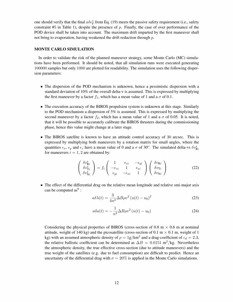
In order to validate the risk of the planned maneuver strategy, some Monte Carlo (MC) simula-tions have been performed. It should be noted, that all simulation runs were executed generating100000 samples but only 1000 are plotted for readability. The simulation uses the following disper-sion parameters:
• The dispersion of the POD mechanism is unknown, hence a pessimistic dispersion with astandard deviation of 10% of the overall delta-v is assumed. This is expressed by multiplyingthe first maneuver by a factor f1, which has a mean value of 1 and a σ of 0.1.
• The execution accuracy of the BIROS propulsion system is unknown at this stage. Similarlyto the POD mechanism a dispersion of 5% is assumed. This is expressed by multiplying thesecond maneuver by a factor f2, which has a mean value of 1 and a σ of 0.05. It is noted,that it will be possible to accurately calibrate the BIROS thrusters during the commissioningphase, hence this value might change at a later stage.
• The BIROS satellite is known to have an attitude control accuracy of 30 arcsec. This isexpressed by multiplying both maneuvers by a rotation matrix for small angles, where thequantities εx, εy and εz have a mean value of 0 and a σ of 30”. The simulated delta-vs δvs
Rifor maneuvers i = 1, 2 are obtained by: δvs
Riδvs
Tiδvs
Ni
= fi
1 εzi −εyi−εzi 1 εxiεyi −εxi 1
δvRiδvTiδvNi
(22)
• The effect of the differential drag on the relative mean longitude and relative smi-major axiscan be computed as9 :
aδλ(t) =3
4n2∆Bρv2 (u(t)− u0)2 (23)
aδa(t) = − 1
n2∆Bρv2 (u(t)− u0) (24)
Considering the physical properties of BIROS (cross-section of 0.8 m × 0.6 m at nominalattitude, weight of 140 kg) and the picosatellite (cross-section of 0.1 m × 0.1 m, weight of 1kg) with an assumed atmospheric density of ρ = 1g/km3 and a drag-coefficient of cd = 2.3,the relative ballistic coefficient can be determined as ∆B = 0.0151 m2/kg. Neverthelessthe atmospheric density, the true effective cross-section (due to attitude maneuvers) and thetrue weight of the satellites (e.g. due to fuel consumption) are difficult to predict. Hence anuncertainty of the differential drag with σ = 20% is applied in the Monte Carlo simulations.
12
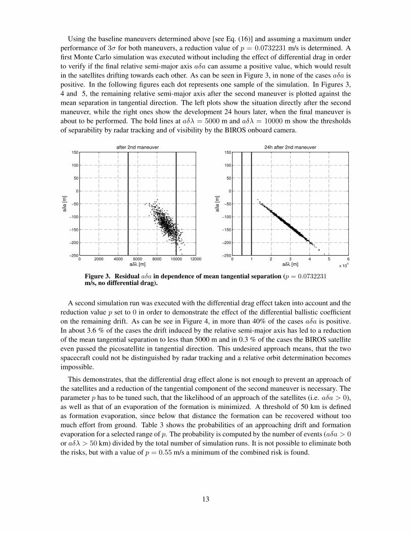
Using the baseline maneuvers determined above [see Eq. (16)] and assuming a maximum underperformance of 3σ for both maneuvers, a reduction value of p = 0.0732231 m/s is determined. Afirst Monte Carlo simulation was executed without including the effect of differential drag in orderto verify if the final relative semi-major axis aδa can assume a positive value, which would resultin the satellites drifting towards each other. As can be seen in Figure 3, in none of the cases aδa ispositive. In the following figures each dot represents one sample of the simulation. In Figures 3,4 and 5, the remaining relative semi-major axis after the second maneuver is plotted against themean separation in tangential direction. The left plots show the situation directly after the secondmaneuver, while the right ones show the development 24 hours later, when the final maneuver isabout to be performed. The bold lines at aδλ = 5000 m and aδλ = 10000 m show the thresholdsof separability by radar tracking and of visibility by the BIROS onboard camera.
0 2000 4000 6000 8000 10000 12000−250
−200
−150
−100
−50
0
50
100
150
after 2nd maneuver
aδλ [m]
aδa [m
]
0 1 2 3 4 5 6
x 104
−250
−200
−150
−100
−50
0
50
100
150
24h after 2nd maneuver
aδλ [m]
aδa [m
]
Figure 3. Residual aδa in dependence of mean tangential separation (p = 0.0732231m/s, no differential drag).
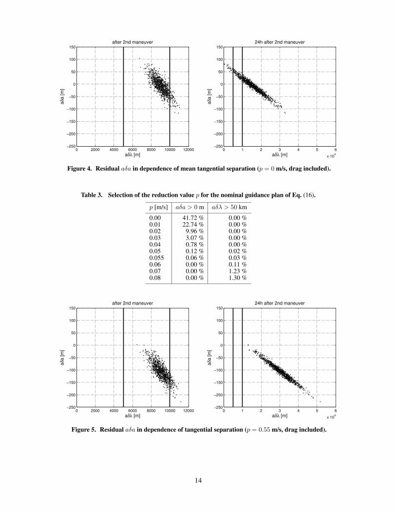
A second simulation run was executed with the differential drag effect taken into account and thereduction value p set to 0 in order to demonstrate the effect of the differential ballistic coefficienton the remaining drift. As can be see in Figure 4, in more than 40% of the cases aδa is positive.In about 3.6 % of the cases the drift induced by the relative semi-major axis has led to a reductionof the mean tangential separation to less than 5000 m and in 0.3 % of the cases the BIROS satelliteeven passed the picosatellite in tangential direction. This undesired approach means, that the twospacecraft could not be distinguished by radar tracking and a relative orbit determination becomesimpossible.
This demonstrates, that the differential drag effect alone is not enough to prevent an approach ofthe satellites and a reduction of the tangential component of the second maneuver is necessary. Theparameter p has to be tuned such, that the likelihood of an approach of the satellites (i.e. aδa > 0),as well as that of an evaporation of the formation is minimized. A threshold of 50 km is definedas formation evaporation, since below that distance the formation can be recovered without toomuch effort from ground. Table 3 shows the probabilities of an approaching drift and formationevaporation for a selected range of p. The probability is computed by the number of events (aδa > 0or aδλ > 50 km) divided by the total number of simulation runs. It is not possible to eliminate boththe risks, but with a value of p = 0.55 m/s a minimum of the combined risk is found.
13
0 2000 4000 6000 8000 10000 12000−250
−200
−150
−100
−50
0
50
100
150
after 2nd maneuver
aδλ [m]
aδa [m
]
0 1 2 3 4 5 6
x 104
−250
−200
−150
−100
−50
0
50
100
150
24h after 2nd maneuver
aδλ [m]
aδa [m
]
Figure 4. Residual aδa in dependence of mean tangential separation (p = 0 m/s, drag included).
Table 3. Selection of the reduction value p for the nominal guidance plan of Eq. (16).
p [m/s] aδa > 0 m aδλ > 50 km
0.00 41.72 % 0.00 %0.01 22.74 % 0.00 %0.02 9.96 % 0.00 %0.03 3.07 % 0.00 %0.04 0.78 % 0.00 %0.05 0.12 % 0.02 %0.055 0.06 % 0.03 %0.06 0.00 % 0.11 %0.07 0.00 % 1.23 %0.08 0.00 % 1.30 %
0 2000 4000 6000 8000 10000 12000−250
−200
−150
−100
−50
0
50
100
150
after 2nd maneuver
aδλ [m]
aδa [m
]
0 1 2 3 4 5 6
x 104
−250
−200
−150
−100
−50
0
50
100
150
24h after 2nd maneuver
aδλ [m]
aδa [m
]
Figure 5. Residual aδa in dependence of tangential separation (p = 0.55 m/s, drag included).
14
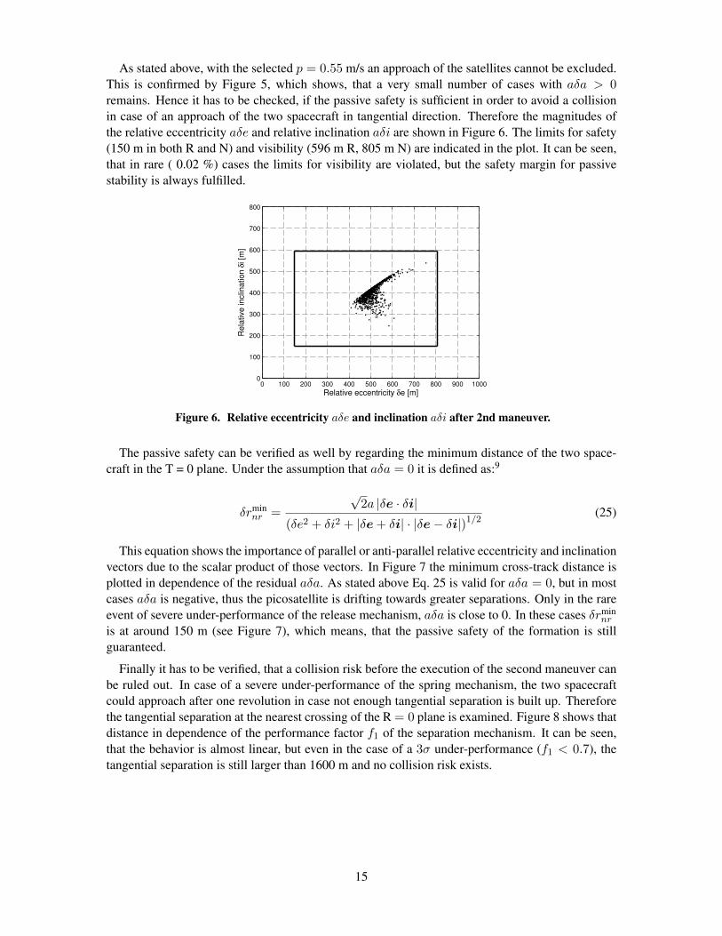
As stated above, with the selected p = 0.55 m/s an approach of the satellites cannot be excluded.This is confirmed by Figure 5, which shows, that a very small number of cases with aδa > 0remains. Hence it has to be checked, if the passive safety is sufficient in order to avoid a collisionin case of an approach of the two spacecraft in tangential direction. Therefore the magnitudes ofthe relative eccentricity aδe and relative inclination aδi are shown in Figure 6. The limits for safety(150 m in both R and N) and visibility (596 m R, 805 m N) are indicated in the plot. It can be seen,that in rare ( 0.02 %) cases the limits for visibility are violated, but the safety margin for passivestability is always fulfilled.
0 100 200 300 400 500 600 700 800 900 10000
100
200
300
400
500
600
700
800
Relative eccentricity δe [m]
Rela
tive inclin
ation δ
i [m
]
Figure 6. Relative eccentricity aδe and inclination aδi after 2nd maneuver.
The passive safety can be verified as well by regarding the minimum distance of the two space-craft in the T = 0 plane. Under the assumption that aδa = 0 it is defined as:9
δrminnr =
√2a |δe · δi|
(δe2 + δi2 + |δe+ δi| · |δe− δi|)1/2(25)
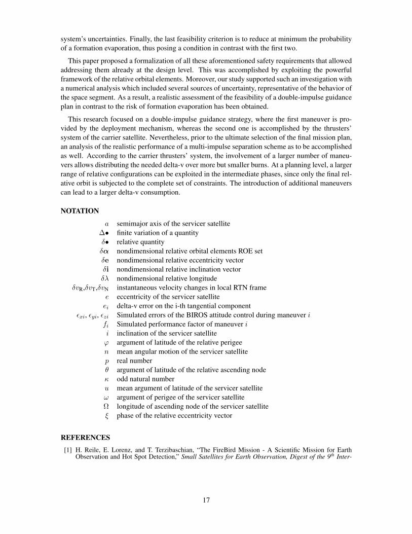
This equation shows the importance of parallel or anti-parallel relative eccentricity and inclinationvectors due to the scalar product of those vectors. In Figure 7 the minimum cross-track distance isplotted in dependence of the residual aδa. As stated above Eq. 25 is valid for aδa = 0, but in mostcases aδa is negative, thus the picosatellite is drifting towards greater separations. Only in the rareevent of severe under-performance of the release mechanism, aδa is close to 0. In these cases δrmin
nr
is at around 150 m (see Figure 7), which means, that the passive safety of the formation is stillguaranteed.
Finally it has to be verified, that a collision risk before the execution of the second maneuver canbe ruled out. In case of a severe under-performance of the spring mechanism, the two spacecraftcould approach after one revolution in case not enough tangential separation is built up. Thereforethe tangential separation at the nearest crossing of the R = 0 plane is examined. Figure 8 shows thatdistance in dependence of the performance factor f1 of the separation mechanism. It can be seen,that the behavior is almost linear, but even in the case of a 3σ under-performance (f1 < 0.7), thetangential separation is still larger than 1600 m and no collision risk exists.
15

−250 −200 −150 −100 −50 0 50100
150
200
250
300
350
400
450
500
aδa [m]δr n
r
min
Figure 7. Minimum cross-track distance in dependence of the final aδa.
0.7 0.8 0.9 1 1.1 1.2 1.3 1.41500
2000
2500
3000
3500
4000
Performance factor of POD
Neare
st cro
ssin
g o
f R
=0 p
lane [m
]
Figure 8. Nearest crossing of the R = 0 plane.
CONCLUSION
This paper addressed the design and the consequent feasibility analysis of the in-orbit release ofa picosatellite from a small satellite carrier in low Earth orbit. This research embodies the prereq-uisite to the execution of the Autonomous Vision Approach Navigation and Target Identification(AVANTI), scheduled for 2015. To this aim, a comprehensive overview of the mission requirementsand of the operational aspects relevant to the mission safety has been provided.
The peculiar scenario of aiming at a mid-range stable formation while employing a release mech-anism that provides a large and strongly uncertain separation delta-v, demanded the complementof the well-known passive safety concept, based on the relative eccentricity/inclination vector sep-aration, with some further feasibility criteria. Specifically, the first one concerns the achievementof the minimum along-track separation to exploit a radar tracking campaign to perform some rel-ative orbit determination. Within our scenario, in fact, this represents the only available source ofnavigation information. The second criterion, closely related to the first one, asks the unavoidableresidual drift to increase the relative separation, regardless of the magnitude and of the nature of the
16
system’s uncertainties. Finally, the last feasibility criterion is to reduce at minimum the probabilityof a formation evaporation, thus posing a condition in contrast with the first two.
This paper proposed a formalization of all these aforementioned safety requirements that allowedaddressing them already at the design level. This was accomplished by exploiting the powerfulframework of the relative orbital elements. Moreover, our study supported such an investigation witha numerical analysis which included several sources of uncertainty, representative of the behavior ofthe space segment. As a result, a realistic assessment of the feasibility of a double-impulse guidanceplan in contrast to the risk of formation evaporation has been obtained.
This research focused on a double-impulse guidance strategy, where the first maneuver is pro-vided by the deployment mechanism, whereas the second one is accomplished by the thrusters’system of the carrier satellite. Nevertheless, prior to the ultimate selection of the final mission plan,an analysis of the realistic performance of a multi-impulse separation scheme as to be accomplishedas well. According to the carrier thrusters’ system, the involvement of a larger number of maneu-vers allows distributing the needed delta-v over more but smaller burns. At a planning level, a largerrange of relative configurations can be exploited in the intermediate phases, since only the final rel-ative orbit is subjected to the complete set of constraints. The introduction of additional maneuverscan lead to a larger delta-v consumption.
NOTATION
a semimajor axis of the servicer satellite∆• finite variation of a quantityδ• relative quantityδα nondimensional relative orbital elements ROE setδe nondimensional relative eccentricity vectorδi nondimensional relative inclination vectorδλ nondimensional relative longitude
δvR,δvT,δvN instantaneous velocity changes in local RTN framee eccentricity of the servicer satelliteei delta-v error on the i-th tangential component
εxi, εyi, εzi Simulated errors of the BIROS attitude control during maneuver ifi Simulated performance factor of maneuver ii inclination of the servicer satelliteϕ argument of latitude of the relative perigeen mean angular motion of the servicer satellitep real numberθ argument of latitude of the relative ascending nodeκ odd natural numberu mean argument of latitude of the servicer satelliteω argument of perigee of the servicer satelliteΩ longitude of ascending node of the servicer satelliteξ phase of the relative eccentricity vector
REFERENCES
[1] H. Reile, E. Lorenz, and T. Terzibaschian, “The FireBird Mission - A Scientific Mission for EarthObservation and Hot Spot Detection,” Small Satellites for Earth Observation, Digest of the 9th Inter-
17

national Symposium of the International Academy of Astronautics, Berlin, Germany, Wissenschaft undTechnik Verlag, 2013. ISBN 978-3-89685-574-9.
[2] B. Engberg, J. Ota, and J. Suchman, “The OPAL Satellite Project: Continuing the Next GenerationSmall Satellite Development,” Proceedings of the 9th Annual AIAA/US Conference on Small Satellites,Logan, Utah, USA, 1995.
[3] J. Puig-Suari, C. Turner, and W. Ahlgren, “Development of the standard CubeSat deployer and a Cube-Sat class PicoSatellite,” Aerospace Conference, 2001, IEEE Proceedings, Vol. 1, 2001, pp. 347–353,10.1109/AERO.2001.931726.
[4] P. G. Ballard, A. Meza, S. Ritterhouse, T. Schaffer, C. Conley, C. Taylor, D. D. D. Atkine, and J. C.McLeroy, “Small Satellite Deployments From STS116 - Development Of New Manned SpaceflightDeployment Systems,” Proceedings of the AIAA/USU Conference on Small Satellites, Technical SessionIII: Launch & Propulsion Systems, 2007, http://digitalcommons.usu.edu/smallsat/2007/all2007/19/.
[5] J. C. Springmann, A. Bertino-Reibstein, and J. W. Cutler, “Investigation of the on-orbit conjunc-tion between the MCubed and HRBE CubeSats,” Aerospace Conference, 2013 IEEE, 2013, pp. 1–8,10.1109/AERO.2013.6497127.
[6] “Poly Picosatellite Orbital Deployer Mk III ICD,” tech. rep., The CubeSat Program Std., 2007,http://cubesat.org/images/LaunchProviders/.
[7] P. Bodin, R. Noteborn, R. Larsson, T. Karlsson, S. D’Amico, J. S. Ardaens, M. Delpech, and J. C.Berges, “Prisma Formation Flying Demonstrator: Overview and Conclusions from the Nominal Mis-sion,” No. 12-072, Breckenridge, Colorado, USA, 35th Annual AAS Guidance and Control Conference,2012.
[8] S. Persson, S. D’Amico, and J. Harr, “Flight Results from PRISMA Formation Flying and RendezvousDemonstration Mission,” Prague, Czech Republic, 61st International Astronautical Congress, 2010.
[9] S. D’Amico, Autonomous Formation Flying in Low Earth Orbit. PhD thesis, Technical University ofDelft, The Netherlands, Mar. 2010.
[10] A. Harting, C. K. Rajasingh, M. C. Eckstein, A. F. Leibold, and K. N. Srinivasamurthy, “On the colli-sion hazard of colocated geostationary satellites,” No. 88-4239, Minneapolis, USA, AIAA/AAS Astro-dynamics conference, 1988.
[11] O. Montenbruck, M. Kirschner, S. D’Amico, and S. Bettadpur, “E/I-Vector Separation for Safe Switch-ing of the GRACE Formation,” Aerospace Science and Technology, Vol. 10, No. 7, 2006, pp. 628–635.doi: 10.1016/j.ast.2006.04.001.
[12] S. D’Amico and O. Montenbruck, “Proximity Operations of Formation Flying Spacecraft using an Ec-centricity/Inclination Vector Separation,” Journal of Guidance, Control and Dynamics, Vol. 29, No. 3,2006, pp. 554–563.
[13] J. Spurmann and S. D’Amico, “Proximity Operations of On-Orbit Servicing Spacecraft using an Ec-centricity/Inclination Vector Separation,” Sao Jose dos Campos, Brazil, 22nd International Symposiumon Spaceflight Dynamics, 2011.
[14] G. Gaias and S. D’Amico, “Impulsive Maneuvers for Formation Reconfiguration using Relative OrbitalElements,” Journal of Guidance, Control, and Dynamics, 2013. accepted for publication.
[15] R. Kahle, M. Weigel, M. Kirschner, S. Spiridonova, E. K. E, and K. Letsch, “Relative Navigation toNon-cooperative Targets in LEO: Achievable Accuracy from Radar Tracking Measurements,” Munich,Germany, 5th International Conference on Spacecraft Formation Flying Missions and Technologies,2013.
[16] S. D’Amico, J. S. Ardaens, G. Gaias, H. Benninghoff, B. Schlepp, and J. L. Jørgensen, “NoncooperativeRendezvous Using Angles-Only Optical Navigation: System Design and Flight Results,” Journal ofGuidance, Control, and Dynamics, Vol. 36, No. 6, 2013, pp. 1576–1595. doi: 10.2514/1.59236.
[17] W. H. Clohessy and R. S. Wiltshire, “Terminal Guidance System for Satellite Rendezvous,” Journal ofthe Aerospace Sciences, Vol. 27, No. 9, 1960, pp. 653–658.
[18] S. D’Amico, “Relative Orbital Elements as Integration Constants of Hill’s Equations,” DLR-GSOC TN05-08, Deutsches Zentrum fur Luft- und Raumfahrt, Oberpfaffenhofen, Germany, Dec. 2005.
18